

Page 1
MultiConnect
MTC-LAT1 User Guide
®
Cell
Page 2

MULTICONNECT® CELL SERIES 100 USER GUIDE
MultiConnect®Cell Series 100 User Guide
Model: MTC-LAT1
Part Number: S000648 1.4
Copyright
This publication may not be reproduced, in whole or in part, without the specific and express prior written permission signed by an executive officer of
Multi-Tech Systems, Inc. All rights reserved. Copyright © 2018 by Multi-Tech Systems, Inc.
Multi-Tech Systems, Inc. makes no representations or warranties, whether express, implied or by estoppels, with respect to the content, information,
material and recommendations herein and specifically disclaims any implied warranties of merchantability, fitness for any particular purpose and noninfringement.
Multi-Tech Systems, Inc. reserves the right to revise this publication and to make changes from time to time in the content hereof without obligation of
Multi-Tech Systems, Inc. to notify any person or organization of such revisions or changes.
Trademarks
MultiTech®, the Multi Tech logo, and MultiConnect are registered trademarks of Multi-Tech Systems, Inc. All other brand and product names are
trademarks or registered trademarks of their respective companies.
Legal Notices
The MultiTech products are not designed, manufactured or intended for use, and should not be used, or sold or re-sold for use, in connection with
applications requiring fail-safe performance or in applications where the failure of the products would reasonably be expected to result in personal injury or
death, significant property damage, or serious physical or environmental damage. Examples of such use include life support machines or other life
preserving medical devices or systems, air traffic control or aircraft navigation or communications systems, control equipment for nuclear facilities, or
missile, nuclear, biological or chemical weapons or other military applications (“Restricted Applications”). Use of the products in such Restricted
Applications is at the user’s sole risk and liability.
MULTITECH DOES NOT WARRANT THAT THE TRANSMISSION OF DATA BY A PRODUCT OVER A CELLULAR COMMUNICATIONS NETWORK WILL BE
UNINTERRUPTED, TIMELY, SECURE OR ERROR FREE, NOR DOES MULTITECH WARRANT ANY CONNECTION OR ACCESSIBILITY TO ANY CELLULAR
COMMUNICATIONS NETWORK. MULTITECH WILL HAVE NO LIABILITY FOR ANY LOSSES, DAMAGES, OBLIGATIONS, PENALTIES, DEFICIENCIES, LIABILITIES,
COSTS OR EXPENSES (INCLUDING WITHOUT LIMITATION REASONABLE ATTORNEYS FEES) RELATED TO TEMPORARY INABILITY TO ACCESS A CELLULAR
COMMUNICATIONS NETWORK USING THE PRODUCTS.
Contacting MultiTech
Knowledge Base
The Knowledge Base provides immediate access to support information and resolutions for all MultiTech products. Visit http://www.multitech.com/kb.go.
Support Portal
To create an account and submit a support case directly to our technical support team, visit: https://support.multitech.com.
Support
Business Hours: M-F, 8am to 5pm CT
Country By Email By Phone
Europe, Middle East, Africa: support@multitech.co.uk +(44) 118 959 7774
U.S., Canada, all others: support@multitech.com (800) 972-2439 or (763) 717-5863
Warranty
To read the warranty statement for your product, visit www.multitech.com/warranty.go. For other warranty options, visit www.multitech.com/es.go.
World Headquarters
Multi-Tech Systems, Inc.
2205 Woodale Drive, Mounds View, MN 55112
Phone: (800) 328-9717 or (763) 785-3500
Fax (763) 785-9874
2 MultiConnect®Cell MTC-LAT1 User Guide
Page 3

CONTENTS
Contents
Chapter 1 – Product Overview ................................................................................................................................. 5
About the MultiConnect Cell Modem........................................................................................................................... 5
Documentation ........................................................................................................................................................... 5
Dimensions.................................................................................................................................................................... 6
Serial............................................................................................................................................................................ 6
Serial with GPS ............................................................................................................................................................ 7
USB.............................................................................................................................................................................. 8
Descriptions of LEDs...................................................................................................................................................... 9
Side Panels .................................................................................................................................................................. 10
MTC-LAT1 Specifications............................................................................................................................................. 11
RS-232 9-Pin Female Connector ................................................................................................................................. 13
Power Measurements................................................................................................................................................. 14
Serial Model: MTC-LAT1-B01 Power Draw ............................................................................................................... 14
Serial Model with GPS: MTC-LAT1-B02 Power Draw................................................................................................ 14
USB Model: MTC-LAT1-B03 Power Draw.................................................................................................................. 15
Chapter 2 – Safety Warnings .................................................................................................................................. 16
Radio Frequency (RF) Safety ....................................................................................................................................... 16
Interference with Pacemakers and Other Medical Devices ...................................................................................... 16
Potential interference ............................................................................................................................................... 16
Precautions for pacemaker wearers ........................................................................................................................ 16
Antenna....................................................................................................................................................................... 17
Chapter 3 – Installing and Using the Device ........................................................................................................... 18
Installing the Device .................................................................................................................................................... 18
Placing Serial Devices in Power Save Mode.............................................................................................................. 18
USB Cable Recommendations................................................................................................................................... 19
Powering Down Your Device ...................................................................................................................................... 19
Installing a SIM Card ................................................................................................................................................... 19
Removing a SIM Card ................................................................................................................................................ 20
Mounting Device to Flat Surface................................................................................................................................. 20
LTE Antenna Diversity ................................................................................................................................................. 20
Selecting Antennas ................................................................................................................................................... 20
Placing External Antennas ........................................................................................................................................ 20
Placing GPS Antennas .............................................................................................................................................. 20
Antenna Approvals and Safety Considerations ........................................................................................................ 21
Diversity and Power Draw ....................................................................................................................................... 21
Chapter 4 – Antenna and Activation Information................................................................................................... 22
Antenna....................................................................................................................................................................... 22
MultiConnect®Cell MTC-LAT1 User Guide 3
Page 4

CONTENTS
Antenna System Cellular Devices................................................................................................................................ 22
LTE Antenna Information ............................................................................................................................................ 22
Antenna Specifications ............................................................................................................................................. 22
GPS Antenna Specifications ........................................................................................................................................ 23
MultiTech Ordering Information............................................................................................................................... 23
Antenna Specifications.............................................................................................................................................. 23
Account Activation for Cellular Devices ..................................................................................................................... 23
Device Phone Number ................................................................................................................................................ 23
Chapter 5 – Configuring and Communicating with Your Device .............................................................................. 24
Interacting with Your Device Overview ...................................................................................................................... 24
Before Using the Device.............................................................................................................................................. 24
Using Command Mode and Online Data Mode.......................................................................................................... 24
Verifying Signal Strength............................................................................................................................................. 25
Example .................................................................................................................................................................... 26
Checking Network Registration................................................................................................................................... 26
Sending and Receiving Data........................................................................................................................................ 26
Connecting Device to TCP Server as TCP Client ........................................................................................................ 26
Configuring Device as UDP Listener to Accept UDP Client Connections ................................................................. 27
Configuring Device as UDP Client to Connect to UDP Server ................................................................................... 28
Transferring FTP File to FTP Server ........................................................................................................................... 29
Downloading File from FTP Server............................................................................................................................ 30
Reading, Writing and Deleting Messages ................................................................................................................... 31
Reading Text Messages............................................................................................................................................. 31
Writing Text Messages.............................................................................................................................................. 31
Deleting Messages .................................................................................................................................................... 32
Chapter 6 – Regulatory Information ....................................................................................................................... 33
Industry Canada Class B Notice................................................................................................................................... 33
Industry Canada and FCC ............................................................................................................................................ 33
47 CFR Part 15 Regulation Class B Devices ............................................................................................................... 33
FCC Interference Notice ............................................................................................................................................ 34
Restriction of the Use of Hazardous Substances (RoHS) ............................................................................................ 34
Information on HS/TS Substances According to Chinese Standards ......................................................................... 35
Information on HS/TS Substances According to Chinese Standards (in Chinese) ...................................................... 36
Chapter 7 – Using Connection Manager ................................................................................................................. 37
Installing Connection Manager and Connecting a Device .......................................................................................... 37
Setting Up a Serial Device ........................................................................................................................................... 38
Troubleshooting .......................................................................................................................................................... 40
Serial COM port is not available in the Serial Modem Settings................................................................................ 40
Device is not detected ("No Device") ....................................................................................................................... 40
MultiConnect Cell USB Modem is not detected ....................................................................................................... 41
4 MultiConnect®Cell MTC-LAT1 User Guide
Page 5
PRODUCT OVERVIEW
Chapter 1 – Product Overview
About the MultiConnect Cell Modem
MultiConnect® Cell 100 Series MTC-LAT1 cellular modems are ready-to-deploy, standalone LTE Category 3 modems
that provide wireless communication. The MTC-LAT1 is a compact communications platform that provides cellular
capabilities for fixed and mobile applications. It is intended for use in energy, utility, or industrial settings. The
MTC-LAT1 is available with RS-232 and optional GPS connector, or as a USB to Cellular device.
Documentation
The following documentation is available on the MultiTech Installation Resources website at
www.multitech.com/setup.product.go.
Document Description
MultiConnect Cell User
Guide
USB Driver Installation Guide
for LTE Devices
LTE AT Commands Reference
Guide
This document provides an overview, safety and regulatory information, schematics,
and general device information. P/N S000648
This document provides instructions on how to install the USB driver of both Linux
and Windows versions for LTE devices. P/N S000616
You can configure the device using the LTE AT Commands. These commands are
documented in the Reference Guide part number S000617.
MultiConnect®Cell MTC-LAT1 User Guide 5
Page 6
PRODUCT OVERVIEW
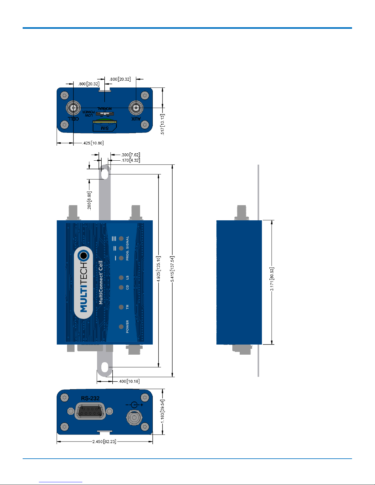
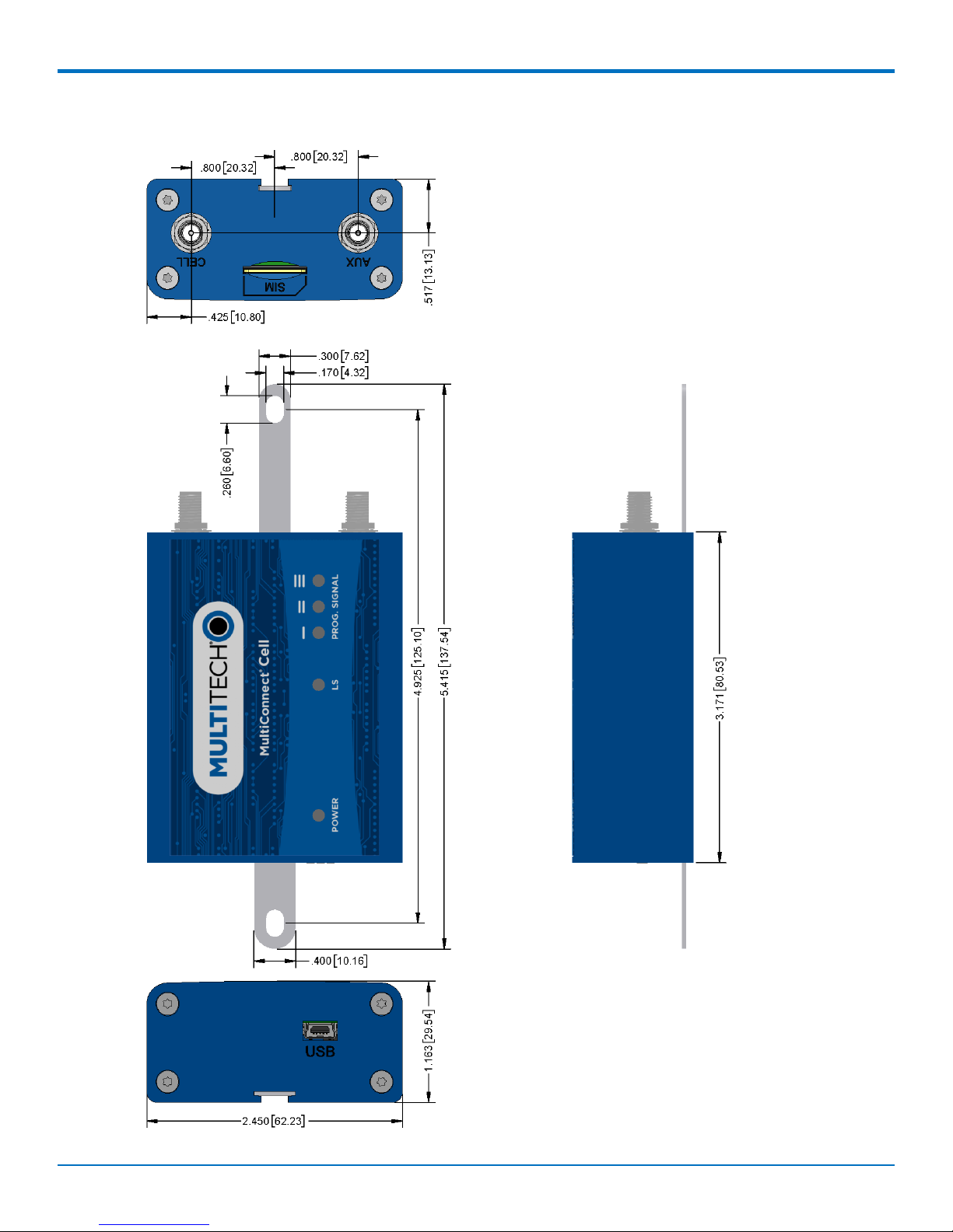
Dimensions
Serial
6 MultiConnect®Cell MTC-LAT1 User Guide
Page 7
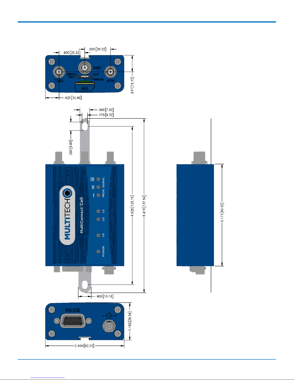
Serial with GPS
PRODUCT OVERVIEW
MultiConnect®Cell MTC-LAT1 User Guide 7
Page 8
PRODUCT OVERVIEW
USB
8 MultiConnect®Cell MTC-LAT1 User Guide
Page 9
PRODUCT OVERVIEW
Descriptions of LEDs
The top panel contains the following LEDs:
Power and Terminal Ready LEDs—The Power LED indicates that DC power is present and the TR LED
indicates when the unit is ready to receive data.
Modem LEDs—Two modem LEDs indicate carrier detection and link status.
Signal LEDs—Three signal LEDs display the signal strength level of the wireless connection.
LED Indicators
POWER Indicates presence of DC power when lit.
TR Terminal Ready. When lit, indicates connection to terminal emulation. When not lit,
indicates no terminal is present.
(for serial only)
CD Carrier Detect. Indicates established data connection when lit.
(for serial only)
LS Link Status.
OFF — No power to the cellular radio
Continuously lit — SIM is not installed, or no signal is present
Slow blink — Powered and searching for a connection, or connected
PROG. SIGNAL To use these LEDS, control them from the host system using the AT#GPIO command. See
the AT Commands Reference Guide for more information.
The LEDs map to particular GPIO on the radio:
GPIO2: Controls the LED with a single bar above it
GPIO3: Controls the LED with two bars above it
GPIO4: Controls the LED with three bars above it
AT command examples:
AT#GPIO=2,0,1 - Turn LED 1 OFF
AT#GPIO=2,1,1 - Turn LED 1 ON
AT#GPIO=3,0,1 - Turn LED 2 OFF
AT#GPIO=3,1,1 - Turn LED 2 ON
AT#GPIO=4,0,1 - Turn LED 3 OFF
AT#GPIO=4,1,1 - Turn LED 3 ON
MultiConnect®Cell MTC-LAT1 User Guide 9
Page 10
PRODUCT OVERVIEW
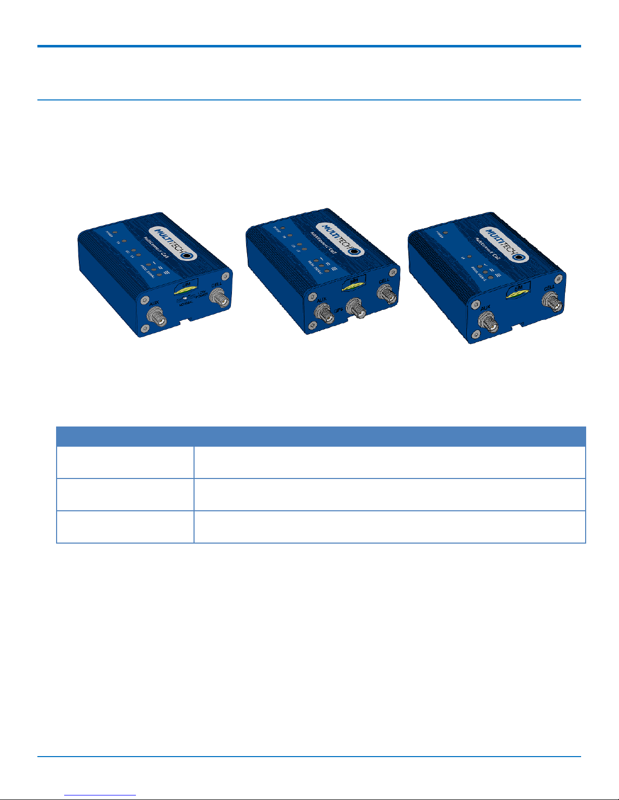
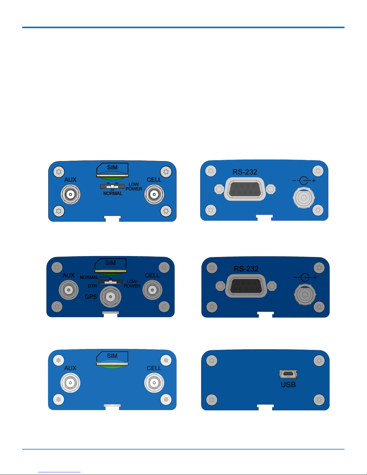
Side Panels
The device has connectors on either side. The figures that follow show the side panels.
Serial
Serial with
GPS
USB
10 MultiConnect®Cell MTC-LAT1 User Guide
Page 11
Note: The power-saving switch—which appears with the NORMAL and LOW POWER labels—is included
only on models that have a serial connector.
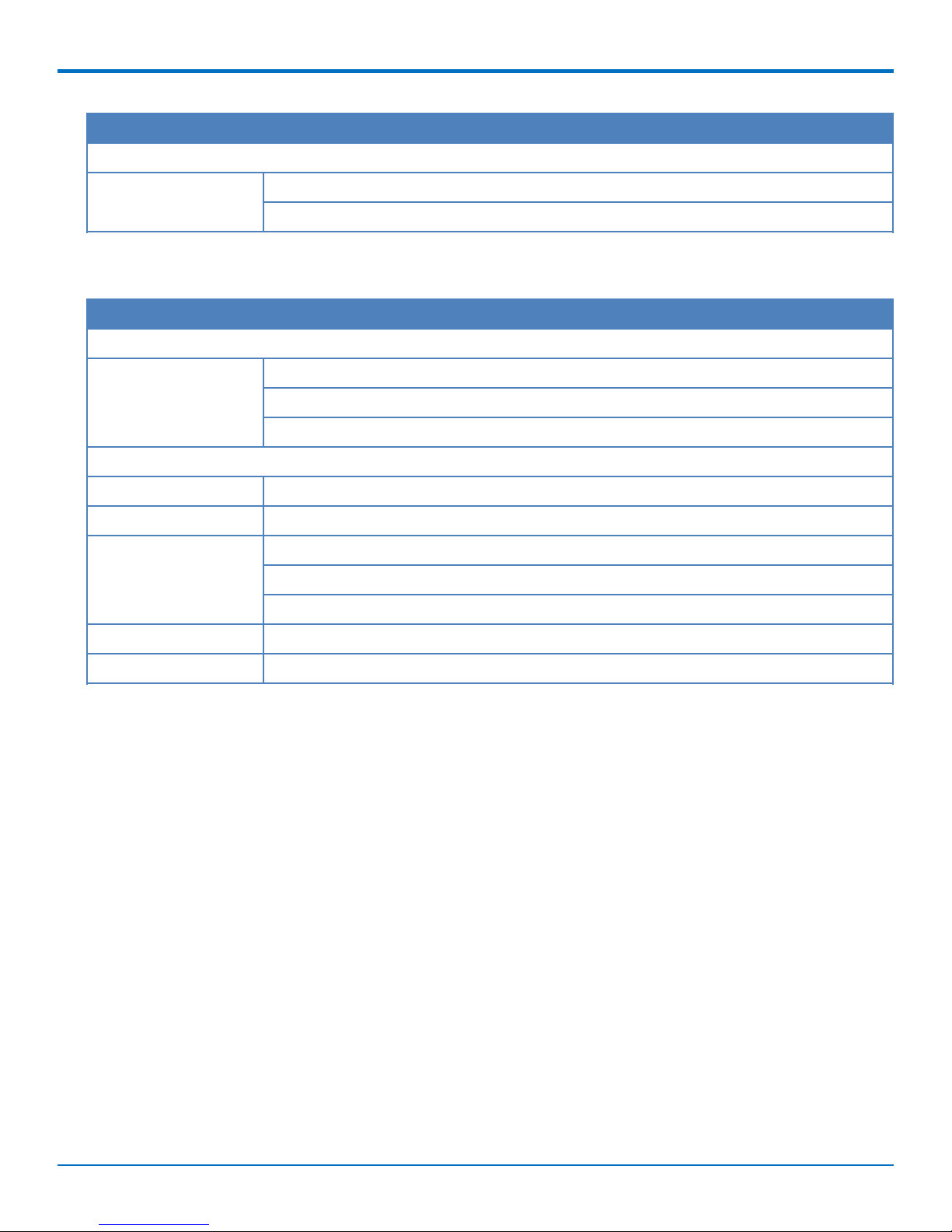
MTC-LAT1 Specifications
Category Description
General
Standards LTE 3GPP Release 9
HSPA+ 21/GPRS fallback
USB interface is CDC-ACM compliant
TCP/IP Functions FTP, SMTP, SSL, TCP, UDP
PRODUCT OVERVIEW
Frequency Bands 4G: 700 (B17)/850 (B5)/AWS 1700 (B4)/1900 (B2)
3G: 850 (B5)/1900 (B2)
2G: 850/1900
Speed
Data Speed LTE: 100 Mbps downlink/50 Mbps uplink
HSPA+: 21 Mbps downlink/5.76 Mbps uplink
Interface
USB Interface USB 2.0 high speed compatible
UART Interface RS-232 levels
Physical Description
Weight 0.4 oz. (10 g)
Dimensions Refer to mechanical drawing for dimensions.
Connectors
Antenna Connectors 2 surface mount SMA connectors for cellular, Rx diversity/MIMO
1 surface mount SMA connector for GPS (Available on the MTC-LAT1-B02 only)
SIM 1.8V and 3V SIM holder for mini-SIM card
Environment
Operating Temperature -40° C to +85° C
Storage Temperature -40° C to +85° C
Humidity 20%-90% RH, non-condensing
MultiConnect®Cell MTC-LAT1 User Guide 11
Page 12
PRODUCT OVERVIEW
Category Description
Power Requirements
Operating Voltage Serial Models: 5-32 VDC
USB Models: 5 VDC
Category Description
SMS
SMS Point-to-Point messaging
Mobile-Terminated SMS
Mobile-Originated SMS
Certifications and Compliance
EMC Compliance FCC Part 15 Class B
Radio Compliance FCC Part 22, 24, 27
Safety Compliance UL 60950-1 2nd ED
cUL 60950-1 2nd ED
IEC 60950-1 2nd ED
Network Compliance PTCRB
Carrier AT&T
12 MultiConnect®Cell MTC-LAT1 User Guide
Page 13
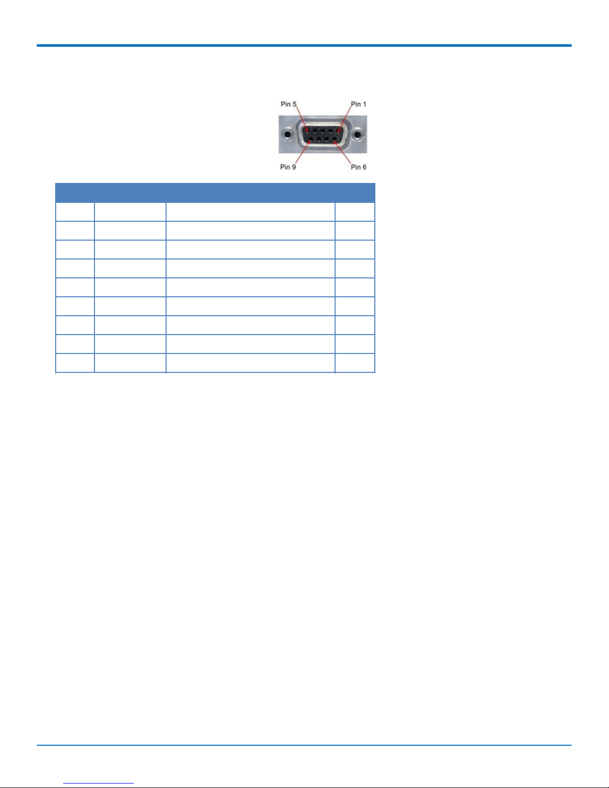
RS-232 9-Pin Female Connector
Pin Abbreviation Description In/Out
1 CD Carrier Detect O
2 RX Receive O
3 TX Transmit I
4 DTR Data Terminal Ready I
5 GND Ground --
6 DSR Data Set Ready O
PRODUCT OVERVIEW
7 RTS Request to Send I
8 CTS Clear to Send O
9 RI Ring Indicator O
MultiConnect®Cell MTC-LAT1 User Guide 13
Page 14

PRODUCT OVERVIEW
Power Measurements
Multi-Tech Systems, Inc. recommends incorporating a 10% buffer into your power source when determining
product load.
Serial Model: MTC-LAT1-B01 Power Draw
Radio
Protocol
9 Volts
GSM
850 MHz
LTE 1900
MHz
12 Volts
GSM
850 MHz
LTE 1900
MHz
24 Volts
GSM
850 MHz
Sleep mode
current,
connected to
wireless
(milliamps)
20 10 28 152 837 0.956 8.87
9 10 29 277 348 0.956 8.87
18 7 26 120 567 0.681 7.01
7 7 29 222 296 0.681 7.01
10 5 16 73 286 1.210 14.2
Sleep mode
current,
connected to
live network,
active SIM
installed
(milliamps)
Cellular call
box
connection,
no data
(milliamps)
Average
measured
current
(milliamps)
at maximum
power
Average TX
pulse
amplitude
current
(milliamps)
Total inrush
charge, in
millicoulomb
s (mC)
Total inrush
charge
duration
during
power-up
(ms)
LTE 1900
MHz
4 4 16 129 196 1.210 14.2
Serial Model with GPS: MTC-LAT1-B02 Power Draw
Radio
Protocol
9 Volts
GSM
850 MHz
LTE 1900
MHz
14 MultiConnect®Cell MTC-LAT1 User Guide
Sleep mode
current,
connected to
wireless
(milliamps)
19 10 24 151 837 0.850 9.46
8 8 26 275 368 0.850 9.46
Sleep mode
current,
connected to
live network,
active SIM
installed
(milliamps)
Cellular call
box
connection,
no data
(milliamps)
Average
measured
current
(milliamps)
at maximum
power
Average TX
pulse
amplitude
current
(milliamps)
Total inrush
charge, in
millicoulomb
s (mC)
Total inrush
charge
duration
during
power-up
(ms)
Page 15

PRODUCT OVERVIEW
Radio
Protocol
Sleep mode
current,
connected to
wireless
(milliamps)
Sleep mode
current,
connected to
live network,
active SIM
Cellular call
box
connection,
no data
(milliamps)
installed
(milliamps)
12 Volts
GSM
17 7 23 120 600 0.750 7.62
850 MHz
LTE 1900
7 6 24 233 300 0.750 7.62
MHz
24 Volts
GSM
10 6 15 70 309 1.260 15.1
850 MHz
LTE 1900
4 4 16 132 200 1.260 15.1
MHz
USB Model: MTC-LAT1-B03 Power Draw
Average
measured
current
(milliamps)
at maximum
power
Average TX
pulse
amplitude
current
(milliamps)
Total inrush
charge, in
millicoulomb
s (mC)
Total inrush
charge
duration
during
power-up
(ms)
Radio
Protocol
Sleep mode
current
(milliamps)
Cellular
connection idle,
no data
(milliamps)
Average
measured current
(milliamps) at
maximum power
Average TX pulse
amplitude current
(milliamps)
Total inrush
charge in
millicoulombs
(mC)
5 Volts
GSM 850
N/A 23.1 231 1080 1.37
MHz
HSDPA
N/A 032 445 516 1.37
1800 MHz
LTE N/A 32 487 552 1.37
MultiConnect®Cell MTC-LAT1 User Guide 15
Page 16

SAFETY WARNINGS
Chapter 2 – Safety Warnings
Radio Frequency (RF) Safety
Due to the possibility of radio frequency (RF) interference, it is important that you follow any special regulations
regarding the use of radio equipment. Follow the safety advice given below.
Operating your device close to other electronic equipment may cause interference if the equipment is
inadequately protected. Observe any warning signs and manufacturers’ recommendations.
Different industries and businesses restrict the use of cellular devices. Respect restrictions on the use of
radio equipment in fuel depots, chemical plants, or where blasting operations are in process. Follow
restrictions for any environment where you operate the device.
Do not place the antenna outdoors.
Switch OFF your wireless device when in an aircraft. Using portable electronic devices in an aircraft may
endanger aircraft operation, disrupt the cellular network, and is illegal. Failing to observe this restriction
may lead to suspension or denial of cellular services to the offender, legal action, or both.
Switch OFF your wireless device when around gasoline or diesel-fuel pumps and before filling your vehicle
with fuel.
Switch OFF your wireless device in hospitals and any other place where medical equipment may be in use.
Interference with Pacemakers and Other Medical Devices
Potential interference
Radio frequency energy (RF) from cellular devices can interact with some electronic devices. This is
electromagnetic interference (EMI). The FDA helped develop a detailed test method to measure EMI of implanted
cardiac pacemakers and defibrillators from cellular devices. This test method is part of the Association for the
Advancement of Medical Instrumentation (AAMI) standard. This standard allows manufacturers to ensure that
cardiac pacemakers and defibrillators are safe from cellular device EMI.
The FDA continues to monitor cellular devices for interactions with other medical devices. If harmful interference
occurs, the FDA will assess the interference and work to resolve the problem.
Precautions for pacemaker wearers
If EMI occurs, it could affect a pacemaker in one of three ways:
Stop the pacemaker from delivering the stimulating pulses that regulate the heart's rhythm.
Cause the pacemaker to deliver the pulses irregularly.
Cause the pacemaker to ignore the heart's own rhythm and deliver pulses at a fixed rate.
Based on current research, cellular devices do not pose a significant health problem for most pacemaker wearers.
However, people with pacemakers may want to take simple precautions to be sure that their device doesn't cause
a problem.
Keep the device on the opposite side of the body from the pacemaker to add extra distance between the
pacemaker and the device.
Avoid placing a turned-on device next to the pacemaker (for example, don’t carry the device in a shirt or
jacket pocket directly over the pacemaker).
16 MultiConnect®Cell MTC-LAT1 User Guide
Page 17

SAFETY WARNINGS
Antenna
The antenna intended for use with this unit meets the requirements for mobile operating configurations and for
fixed mounted operations, as defined in 2.1091 and 1.1307 of the FCC rules for satisfying RF exposure compliance.
If an alternate antenna is used, consult user documentation for required antenna specifications.
MultiConnect®Cell MTC-LAT1 User Guide 17
Page 18

INSTALLING AND USING THE DEVICE
Chapter 3 – Installing and Using the Device
Installing the Device
1. Connect suitable antenna(s) to the antenna connector(s).
2. If your device is the serial version:
Connect the DE9 male connector (9-pin) of the RS-232 cable to the RS-232 connector on the device, then
connect the other end to the serial port on the other desired device.
Screw-on the power lead from the power supply module into the power connection on the device.
Plug the power supply into your power source.
3. If your device is the USB version:
For information about the USB cable that helps power your device, see the section "USB Cable
Recommendations."
The USB cable uses power from the USB power line. Connect one end of the USB cable to your computer
or other USB high power device, such as a hub.
Connect the other end to the device's USB connector.
4. The POWER LED lights after the device powers up.
Placing Serial Devices in Power Save Mode
The serial devices offer a low power mode (sleep or power save mode) using the power save switch (below the
SIM card slot) on the device to change from normal or low power mode. The low power mode is intended for
battery or solar-powered, IoT applications such as outdoor remote sensors.
There are other techniques to place the device into low power mode. This example uses data terminal ready (DTR)
and the AT command +CFUN=5. For other techniques, review the AT command guide for your device, as described
in the Documentation section of this guide.
The device also wakes up from sleep mode by using the wake-on-ring feature. See the following example using the
ring indicator line to wake the host processor when the radio receives an incoming call or SMS message. Your
application then needs to act on the ring indication and wake up the device by asserting DTR.
Using Low Power Mode
Here are some different configuration options for low power mode:
To turn on low power mode, set the power-save switch to LOW.
On the RS-232 interface, ensure your application controls DTR and makes it active (on). To configure the
device for DTR control, issue either AT&D1 or AT&D2 for DTR control. The &D0 command does not allow
low power to operate.
To configure the device to enter low power (sleep) mode, issue AT+CFUN=5 to the radio.
To configure the device to wake from low power mode by using the wake-on-ring feature, issue
AT#E2SMSRI=1000. This configures the ring indicator to go active for 1000 ms when an SMS message is
received.
To have the device enter sleep mode, set DTR to inactive (off) on the RS-232 interface. The clear to send
(CTS) signal is off when the device is in sleep mode.
18 MultiConnect®Cell MTC-LAT1 User Guide
Page 19

INSTALLING AND USING THE DEVICE
USB Cable Recommendations
If your device has a USB connector, to avoid enumeration or power issues:
Use a high-speed USB cable that is as short as possible.
Use a well-shielded cable with at least 24 AWG wire pair for power/ground and 28 AWG wire pair for data
lines.
If possible, use a USB port that connects directly to the motherboard rather than a USB port with added
cabling inside the computer chassis.
Use USB 3.0 ports if available. These ports are typically rated for more current.
You can order the USB cable through MultiTech. The part number is CA-USB-A-MINI-B-3
Powering Down Your Device
CAUTION: Failing to properly power down the device before removing power may corrupt your device's file
system.
To properly power down your device, use the following sequence :
1. Issue the AT#SHDN command.
2. Wait 30 seconds.
3. Power off or disconnect power.
Note: If you send AT#SHDN and do not remove power, the radio restarts after 60 seconds.
Installing a SIM Card
This model requires a SIM card, which is supplied by your service provider. To install the SIM card:
1. Locate the SIM card slot on the side of the modem. The slot is labeled SIM.
2. Slide the SIM card into the SIM card slot with the contact side facing down as shown. When the SIM card
is installed, it locks into place.
MultiConnect®Cell MTC-LAT1 User Guide 19
Page 20

INSTALLING AND USING THE DEVICE
Removing a SIM Card
To remove the SIM card, push the SIM card in. The device ejects the SIM card.
Mounting Device to Flat Surface
1. Locate the groove on the bottom of the device.
2. Slide the mounting bracket through the groove.
3. To secure the bracket to the desired surface, place and tighten two screws in the holes on either end of
the mounting bracket. The dimensions illustration in this guide shows the mounting bracket, as well as
the dimensions for placement of the screws.
LTE Antenna Diversity
Antenna diversity uses two receive antennas to improve the downlink connection (cell tower to mobile). It has no
effect on the uplink (mobile to cell tower).
Antenna diversity is useful in environments where the signal arrives at the device after bouncing off or around
buildings or other objects. The bounced signal may be attenuated by going through semi-transparent (to the
signal) objects. Each signal alteration can change its magnitude, phase, orientation, or polarization. This complex
environment can exist in cities, inside buildings or in traffic. In this environment, signal paths from the cell tower
form an interference pattern of peaks and nulls. These peaks and nulls can be very close together.
Antenna diversity provides an advantage in complex environments because if one receive antenna has a poor
signal due to an interference null pattern, the other antenna is likely not in the null and has better reception. The
radio compares the reception from both receive antennas and uses the one with the strongest signal.
Important: You must deploy with two antennas, unless your carrier has authorized you to deploy with one
antenna.
Selecting Antennas
Select an antenna based on your product and application. Typically, both antennas are the same and either can be
the main receive antenna.
Placing External Antennas
Antennas are usually a quarter wavelength apart from each other. With multiband radios where the quarter
wavelengths in each band are diverse from each other, this rule may not be practical. Choose spacing based on the
band used most often or the band with connection difficulty. Some environments are harsher on particular bands.
MultiTech products have antenna connectors at the best spacing for the product size.
Placing antennas in close proximity to each other is not optimal, but you can do it if necessary. It depends on the
signal strength to and from each antenna.
If the antennas are too close together for your application, use a similar antenna on a short cable for the second
receive only antenna.
Placing GPS Antennas
GPS antennas need a clear view of the sky. Position the GPS antenna so the diversity antennas do not block its
view of the sky.
20 MultiConnect®Cell MTC-LAT1 User Guide
Page 21

Antenna Approvals and Safety Considerations
Note the following:
Carriers conduct antenna diversity tests.
There are no EMC concerns about antenna diversity.
All antennas need to have a minimum flammability rating.
Safety requirements depend on your final product.
Unless otherwise noted, antennas certified by MultiTech are not approved for outdoor use. Do not extend
these antennas outside of any building.
Diversity and Power Draw
There are no significant power draw differences.
INSTALLING AND USING THE DEVICE
MultiConnect®Cell MTC-LAT1 User Guide 21
Page 22

ANTENNA AND ACTIVATION INFORMATION
Chapter 4 – Antenna and Activation Information
Antenna
The antenna intended for use with this unit meets the requirements for mobile operating configurations and for
fixed mounted operations, as defined in 2.1091 and 1.1307 of the FCC rules for satisfying RF exposure compliance.
If an alternate antenna is used, consult user documentation for required antenna specifications.
Antenna System Cellular Devices
The cellular/wireless performance depends on the implementation and antenna design. The integration of the
antenna system into the product is a critical part of the design process; therefore, it is essential to consider it early
so the performance is not compromised. If changes are made to the device's certified antenna system, then
recertification will be required by specific network carriers.
LTE Antenna Information
The cellular radio portion of the device is approved with the following antenna or for alternate antennas meeting
the given specifications.
Manufacturer: EAD Ltd.
Description: LTE Antenna with SMA-Male Connector
Model Number: WTR7270
MultiTech Part Number: 45009760L
MultiTech ordering information:
Model Quantity
ANLTE3-2HRA 2
ANLTE3-10HRA 10
ANLTE3-50HRA 50
Antenna Specifications
Category Description
Frequency Range 690-960 MHz
1710-2700 MHz
Power Rating 10 W
VSWR < 2.0:1
Gain 1 dBi
Radiating Element 1/2 wave element
Polarization Linear
22 MultiConnect®Cell MTC-LAT1 User Guide
Page 23

GPS Antenna Specifications
Manufacturer: Trimble
Description: GPS Antenna with low noise amplifier
Model Number: 66800-52
Multi-Tech Part Number: 45009665L
MultiTech Ordering Information
Model Quantity
ANGPS-1MM 1
ANGPS-10MM 10
ANGPS-50MM 50
Antenna Specifications
ANTENNA AND ACTIVATION INFORMATION
Category Description
Frequency Range 1575.24 MHz
Impedance 50 Ohms
VSWR 2.0:1 max
Gain 10-30 dBi
LNA Current Consumption 40 mA max
Noise Figure < 2dB
Polarization RHCP
Input voltage 3.0V M M 0.2V
Account Activation for Cellular Devices
Some MultiTech devices are pre-configured to operate on a specific cellular network. To use the device, you must
set up a cellular data account with your service provider. Each service provider has its own process for adding
devices to their network.
Device Phone Number
Every device has a unique phone number. Your service provider supplies a phone number when you activate your
account. Wireless service provider implementation may vary. Consult with your service provider to get the phone
number for your device.
MultiConnect®Cell MTC-LAT1 User Guide 23
Page 24

CONFIGURING AND COMMUNICATING WITH YOUR DEVICE
Chapter 5 – Configuring and Communicating with
Your Device
Interacting with Your Device Overview
This section describes how to use AT commands to interact with your device. Using terminal software such as
Kermit, you can issue AT commands to communicate with and configure your modem. The AT commands let you
establish, read and modify device parameters and help you control how the device operates. This section
documents basic interactions with your device, such as verifying signal strength and network registrations, sending
and reading SMS text messages, and sending and receiving data.
Generally, USB modems are used as unintelligent bit pipes. In Windows, this means you create a dial-up network
connection that uses the Windows IP stack to use the modem to create a PPP connection to the cellular network.
The modem is assigned an IP address from the cellular carrier. This connection provides Internet access and is the
basis for TCP/IP communication for sending and receiving email, creating TCP/UDP Sockets, or putting and getting
files from an FTP server.
In Linux, PPPD is used to dial the modem and create the connection to the cellular TCP/IP network. This provides
Internet access for sending and receiving email, creating TCP/UDP Sockets, or putting and getting files from an FTP
server.
Before Using the Device
Before using the device:
Install any drivers. Refer to the separate driver installation guide for your device.
Power up your device and ensure it is connected to your computer that issues AT commands.
Note: Wait 10 seconds after power-up before issuing any AT commands.
Install terminal software that can communicate with the device, such as HyperTerminal, Tera Term, Kermit,
or Putty.
Using Command Mode and Online Data Mode
Modems have two operation modes, command and online data. After power up, the modem is in command mode
and ready to accept AT commands.
Use AT commands to communicate with and configure your modem. These commands establish, read, and modify
device parameters and control how the modem works. The device also generates responses to AT commands that
help determine the modem’s current state.
If the modem is in online data mode, it only accepts the Escape command (+++).
To send the modem AT Commands from terminal emulation software, set the software to match the modem’s
default data format, which is:
Speed: 115,200 bps
Data bits: 8
Parity: none
24 MultiConnect®Cell MTC-LAT1 User Guide
Page 25

Stop bit: 1
Flow control: hardware
To confirm communication with the device:
Type AT and press Enter.
If the device responds with OK, it is properly communicating.
Verifying Signal Strength
To verify the device signal strength, enter:
AT+CSQ
The command indicates signal quality, in the form:
+CSQ: <rssi>,<ber>
Where:
<rssi> Received signal strength indication.
CONFIGURING AND COMMUNICATING WITH YOUR DEVICE
0 (-113) dBm or less
1 (-111) dBm
2-30 (-109) dBm - (-53) dBm / 2 dBm per step
31 (-51) dBm or greater
99 Not known or not detectable
<ber> Bit error rate, in percent
0 Less than 0.2%
1 0.2% to 0.4%
2 0.4% to 0.8%
3 0.8% to 1.6%
4 1.6% to 3.2%
5 3.2% to 6.4%
6 6.4% to 12.8%
7 More than 12.8%
99 Not known or not detectable
Note: Signal strength of 10 or higher is needed for successful packet data sessions.
MultiConnect®Cell MTC-LAT1 User Guide 25
Page 26

CONFIGURING AND COMMUNICATING WITH YOUR DEVICE
Example
A example response to AT+CSQ:
+CSQ: 15,1
Checking Network Registration
Before establishing a packet data connection, verify the is device registered on the network. To do this enter the
network registration report read command:
AT+CREG?
If the device returns:
+CREG: 0,1
or
+CREG: 0,5
The device is registered.
If the device returns:
+CREG: 0,2
The device is in a network searching state.
Sending and Receiving Data
Connecting Device to TCP Server as TCP Client
1. Bring up Data Connection Using Internal IP stack
Enter:
AT#SGACT=1,1
The device responds with the IP Address the cellular provider assigned to the device on connection,
followed by OK. For example:
#SGACT: 25.194.185.116
OK
2. Create Client Connection to TCP Server on Port 500
Enter:
AT#SD=1,0,500,"###.##.###.##"
where ###.##.###.## is the TCP server IP Address.
The device responds with OK. You can now send or receive data without entering additional commands.
Closing the Socket and the Connection
To close the socket:
Enter the escape sequence:
+++
To close Socket 1, enter:
26 MultiConnect®Cell MTC-LAT1 User Guide
Page 27

CONFIGURING AND COMMUNICATING WITH YOUR DEVICE
AT#SH=1
The device responds with OK.
To close the data connection:
Enter:
AT#SGACT=1,0
The device responds with OK.
Configuring Device as UDP Listener to Accept UDP Client Connections
To configure the device as a UDP client:
1. Check signal strength.
Enter:
AT+CSQ
2. Verify device is registered on the cellular network.
Enter:
Should return:
+CREG 0,1
OK
3. Configure socket parameters
Enter:
AT#SCFG=1,1,300,240,600,50
4. Activate context one
Enter:
AT#SGACT=1,1
5. Set firewall rule to accept connections:
AT#FRWL=1,"###.##.###.#","###.##.###.#"
where ###.##.###.# represents the IP range. For example:
AT#FRWL=1,"204.26.122.1","204.26.122.255"
6. Set connection ID 1 for UDP listening mode on port 7000.
Enter:
AT#SLUDP=1,1,7000
The device responds with and unsolicited indication that a host is trying to connect to connection ID 1 on
port 7000.
SRING: 1
7. Accept incoming connection ID 1
Enter:
AT#SA=1
The device indicates a client successfully established a listener connection.
CONNECT
You can send and receive data.
MultiConnect®Cell MTC-LAT1 User Guide 27
Page 28

CONFIGURING AND COMMUNICATING WITH YOUR DEVICE
Exit Data Mode and Close Connection
To exit data mode and close the socket:
Enter the escape sequence:
+++
To close Socket 1, enter:
AT#SH=1
The device responds with OK.
To close the data connection, enter:
AT#SGACT=1,0
The device responds with OK.
Configuring Device as UDP Client to Connect to UDP Server
Configure and Connect the Device
To configure the device as a UDP client:
1. Check signal strength.
Enter:
AT+CSQ
2. Verify device is registered on the cellular network.
Enter:
Should return:
+CREG: 0,1
OK
3. Configure socket parameters
Enter:
AT#SCFG=1,1,300,240,600,50
4. Activate context one
Enter:
AT#SGACT=1,1
5. Create UDP connection to Server port
Enter:
AT#SD=1,1,####,"###.##.###.##"
where #### is the server port and ###.##.###.## is the IP number.
The device responds with OK, which indicates a successful connection. You can send and receive data through the
socket connection.
Exit Data Mode and Close Connection
To exit data mode and close the socket:
Enter the escape sequence:
+++
To close Socket 1, enter:
28 MultiConnect®Cell MTC-LAT1 User Guide
Page 29

CONFIGURING AND COMMUNICATING WITH YOUR DEVICE
AT#SH=1
The device responds with OK.
To close the data connection, enter:
AT#SGACT=1,0
The device responds with OK.
Transferring FTP File to FTP Server
To connect to FTP server and upload files:
1. Check signal strength.
Enter:
AT+CSQ
2. Activate context one
Enter:
AT#SGACT=1,1
3. Set FTP operations timeout to 10 seconds
Enter:
AT#FTPTO=1000
4. Configure FTP server IP address with username and password.
Enter:
AT#FTPOPEN="###.##.###.#","username","password",0
where ###.##.###.# is the IP address and the username and password for the FTP server.
5. Configure file transfer type.
Enter:
AT#FTPTYPE=#
where # is 0 for binary or 1 for ASCII.
6. Enter the file name to be sent to the FTP server and initiate connection.
Enter:
AT#FTPPUT="file.txt"
The device responds with:
CONNECT
7. Send the file through the device.
Closing the FTP Data Connection
When you finish sending the file:
1. Enter the escape sequence.
Enter:
+++
The device responds with:
NO CARRIER
2. Close the FTP connection.
Enter:
MultiConnect®Cell MTC-LAT1 User Guide 29
Page 30

CONFIGURING AND COMMUNICATING WITH YOUR DEVICE
AT#FTPCLOSE
3. Close the PPP data connection.
Enter:
AT#SGACT=1,0
The device responds with OK.
Downloading File from FTP Server
To connect to an FTP server and download files:
1. Check signal strength.
Enter:
AT+CSQ
2. Activate context one
Enter:
AT#SGACT=1,1
3. Set FTP operations timeout to 10 seconds
Enter:
AT#FTPTO=1000
4. Configure FTP server IP address with username and password.
Enter:
AT#FTPOPEN="###.##.###.#","username","password",0
where ###.##.###.# is the IP address and the username and password for the FTP server.
5. Configure file transfer type.
Enter:
AT#FTPTYPE=#
where # is 0 for binary or 1 for ASCII.
6. If required, change the working directory to "folder1".
Enter:
AT#FTPCWD="folder1"
7. Enter the file name.
Enter:
AT#FTPGET="filename.txt"
where filename.txt is the file you want to download.
The device responds with:
CONNECT
The file is received through the device. The device responds with:
NO CARRIER
The data connection closes automatically when the file sending ends.
Closing the FTP Data Connection
When you finish sending the file:
1. Close the FTP connection.
Enter:
30 MultiConnect®Cell MTC-LAT1 User Guide
Page 31

CONFIGURING AND COMMUNICATING WITH YOUR DEVICE
AT#FTPCLOSE
2. Close the PPP data connection.
Enter:
AT#SGACT=1,0
The device responds with OK.
Reading, Writing and Deleting Messages
Reading Text Messages
To read a text message in text mode:
1. Put the device in text mode.
Enter:
AT+CMGF=1
2. Read message.
Enter:
AT+CMGR=1
Example response:
+CMGR: "REC UNREAD","+10001112222z`z","","13/09/05,13:39:40-20"
How are you?
OK
Where 0001112222 is the phone number.
Writing Text Messages
To send a text message in text mode:
1. Put the device in text mode.
Enter:
AT+CMGF=1
The device responds.
OK
2. Enter the recipient's number and your message.
Enter:
AT+CMGS="##########"
>Your message here
where ########## is the recipient's number.
3. Send the message.
Enter CTRL+Z.
The device responds:
+CMGS: #
OK
where # is the reference number of the sent message.
For example:
MultiConnect®Cell MTC-LAT1 User Guide 31
Page 32

CONFIGURING AND COMMUNICATING WITH YOUR DEVICE
AT+CMGF=1
OK
AT+CMGS="0001112222"
> How are you? <CTRL+Z to send>
+CMGS: 255
OK
Where 0001112222 is the phone number.
Deleting Messages
To delete one text message, enter:
AT+CMGD=I,#
where I is the index in the select storage and # is the delflag option. Enter:
0 Deletes message in the specified index.
1 Deletes all read messages. Leaves unread messages and stored device-
originated messages.
2 Deletes all read and sent device-originated messages. Leaves unread messages
and unsent device-originated messages.
3 Deletes all read messages and sent and unsent device-orginated messages.
Leaves unread messages.
4 Deletes all messages.
For example:
AT+CMGD=1 (delete message at index 1)
AT+CMGD=2 (delete message at index 2 )
AT+CMGD=1,0
AT+CMGD=1,1
AT+CMGD=1,2
AT+CMGD=1,3
AT+CMGD=1,4
32 MultiConnect®Cell MTC-LAT1 User Guide
Page 33

REGULATORY INFORMATION
Chapter 6 – Regulatory Information
Industry Canada Class B Notice
This Class B digital apparatus meets all requirements of the Canadian Interference-Causing Equipment Regulations.
Cet appareil numérique de la classe B respecte toutes les exigences du Reglement Canadien sur le matériel
brouilleur.
This device complies with Industry Canada license-exempt RSS standard(s). The operation is permitted for the
following two conditions:
1. the device may not cause interference, and
2. this device must accept any interference, including interference that may cause undesired operation of
the device.
Le présent appareil est conforme aux CNR d'Industrie Canada applicables aux appareils radio exempts de licence.
L'exploitation est autorisée aux deux conditions suivantes:
1. l'appareil ne doit pas produire de brouillage, et
2. l’appareil doit accepter tout brouillage radioélectrique subi, même si le brouillage est susceptible d’en
compromettre le fonctionnement.
Industry Canada and FCC
This device complies with Industry Canada licence-exempt RSS standard(s) and part 15 of the FCC rules. Operation
is subject to the following two conditions:
(1) this device may not cause interference, and
(2) this device must accept any interference, including interference that may cause undesired operation of the
device.
Cet appareil est conforme avec Industrie Canada RSS exemptes de licence standard (s) et la partie 15 des règles de
la FCC. Son fonctionnement est soumis aux deux conditions suivantes:
1. l'appareil ne doit pas produire de brouillage, et
2. l'utilisateur de l'appareil doit accepter tout brouillage radioélectrique subi, même si le brouillage est susceptible
d'en compromettre le fonctionnement.
47 CFR Part 15 Regulation Class B Devices
This equipment has been tested and found to comply with the limits for a Class B digital device, pursuant to part
15 of the FCC Rules. These limits are designed to provide reasonable protection against harmful interference in a
residential installation. This equipment generates, uses, and can radiate radio frequency energy and, if not installed
and used in accordance with the instructions, may cause harmful interference to radio communications. However,
there is no guarantee that interference will not occur in a particular installation. If this equipment does cause
harmful interference to radio or television reception, which can be determined by turning the equipment off and
on, the user is encouraged to try to correct the interference by one or more of the following measures:
Reorient or relocate the receiving antenna.
Increase the separation between the equipment and receiver.
MultiConnect®Cell MTC-LAT1 User Guide 33
Page 34

REGULATORY INFORMATION
Connect the equipment into an outlet on a circuit different from that to which the receiver is connected.
Consult the dealer or an experienced radio/TV technician for help.
Warning: Changes or modifications to this unit not expressly approved by the party responsible for compliance
could void the user’s authority to operate the equipment.
FCC Interference Notice
This device complies with part 15 of the FCC Rules. Operation is subject to the following two conditions:
1. This device may not cause harmful interference, and
2. This device must accept any interference received, including interference that may cause undesired
operation.
Restriction of the Use of Hazardous Substances (RoHS)
Multi-Tech Systems, Inc.
Certificate of Compliance
2011/65/EU
Multi-Tech Systems, Inc. confirms that its embedded products comply with the chemical concentration limitations
set forth in the directive 2011/65/EU of the European Parliament (Restriction of the use of certain Hazardous
Substances in electrical and electronic equipment - RoHS).
These MultiTech products do not contain the following banned chemicals1:
Lead, [Pb] < 1000 PPM
Mercury, [Hg] < 1000 PPM
Hexavalent Chromium, [Cr+6] < 1000 PPM
Cadmium, [Cd] < 100 PPM
Polybrominated Biphenyl, [PBB] < 1000 PPM
Polybrominated Diphenyl Ether, [PBDE] < 1000 PPM
Environmental considerations:
Moisture Sensitivity Level (MSL) =1
Maximum Soldering temperature = 260C (in SMT reflow oven)
1
Lead usage in some components is exempted by the following RoHS annex, therefore higher lead concentration
would be found in some modules (>1000 PPM);
- Resistors containing lead in a glass or ceramic matrix compound.
34 MultiConnect®Cell MTC-LAT1 User Guide
Page 35

REGULATORY INFORMATION
Information on HS/TS Substances According to Chinese Standards
In accordance with China's Administrative Measures on the Control of Pollution Caused by Electronic Information
Products (EIP) # 39, also known as China RoHS, the following information is provided regarding the names and
concentration levels of Toxic Substances (TS) or Hazardous Substances (HS) which may be contained in Multi-Tech
Systems Inc. products relative to the EIP standards set by China's Ministry of Information Industry (MII).
Hazardous/Toxic Substance/Elements
Name of the Component Lead
(PB)
Printed Circuit Boards O O O O O O
Resistors X O O O O O
Capacitors X O O O O O
Ferrite Beads O O O O O O
Relays/Opticals O O O O O O
ICs O O O O O O
Diodes/ Transistors O O O O O O
Oscillators and Crystals X O O O O O
Regulator O O O O O O
Voltage Sensor O O O O O O
Transformer O O O O O O
Speaker O O O O O O
Connectors O O O O O O
Mercury
(Hg)
Cadmium
(CD)
Hexavalent
Chromium
(CR6+)
Polybromi
nated
Biphenyl
(PBB)
Polybrominat
ed Diphenyl
Ether (PBDE)
LEDs O O O O O O
Screws, Nuts, and other
Hardware
AC-DC Power Supplies O O O O O O
Software /Documentation CDs O O O O O O
Booklets and Paperwork O O O O O O
Chassis O O O O O O
X Represents that the concentration of such hazardous/toxic substance in all the units of homogeneous
material of such component is higher than the SJ/Txxx-2006 Requirements for Concentration Limits.
O Represents that no such substances are used or that the concentration is within the aforementioned limits.
MultiConnect®Cell MTC-LAT1 User Guide 35
X O O O O O
Page 36

REGULATORY INFORMATION
Information on HS/TS Substances According to Chinese Standards (in
Chinese)
依依照照中中国国标标准准的的有有毒毒有有害害物物质质信信息息
根据中华人民共和国信息产业部 (MII) 制定的电子信息产品 (EIP) 标准-中华人民共和国《电子信息产品污染
控制管理办法》(第 39 号),也称作中国 RoHS, 下表列出了 Multi-Tech Systems, Inc. 产品中可能含有的有毒
物质 (TS) 或有害物质 (HS) 的名称及含量水平方面的信息。
有有害害//有有毒毒物物质质//元元素素
成成分分名名称称
印刷电路板
电阻器
电容器
铁氧体磁环
继电器/光学部件
ICs O O O O O O
二极管/晶体管
振荡器和晶振
调节器
电压传感器
变压器
扬声器
连接器
LEDs O O O O O O
铅铅 (PB) 汞汞 (Hg) 镉镉 (CD) 六六价价铬铬 (CR6+)
O O O O O O
X O O O O O
X O O O O O
O O O O O O
O O O O O O
O O O O O O
X O O O O O
O O O O O O
O O O O O O
O O O O O O
O O O O O O
O O O O O O
多多溴溴联联苯苯
(PBB)
多多溴溴二二苯苯醚醚
(PBDE)
螺丝、螺母以及其它五金件
交流-直流电源
软件/文档 CD
手册和纸页
底盘
X 表示所有使用类似材料的设备中有害/有毒物质的含量水平高于 SJ/Txxx-2006 限量要求。
O 表示不含该物质或者该物质的含量水平在上述限量要求之内。
36 MultiConnect®Cell MTC-LAT1 User Guide
X O O O O O
O O O O O O
O O O O O O
O O O O O O
O O O O O O
Page 37

USING CONNECTION MANAGER
Chapter 7 – Using Connection Manager
Use Connection Manager to install device drivers and connect your device to your carrier's network.
Connection Manager can install drivers and connect your device regardless of your CDMA network, however,
activation is only supported with Verizon, Aeris, Sprint, and some CDMA Regional Carriers. If you cannot activate
your device with Connection Manager, refer to Account Activation for Cellular Devices.
Connection Manager supports the following Windows versions:
Windows 7 and 8 and Windows 10, both 32-bit and 64-bit versions
Installing Connection Manager and Connecting a Device
Follow these steps in order. Attempting to plug in the device before the appropriate drivers are installed can cause
the connection to fail.
1. Go to https://www.multitech.com/support/connection-manager.
2. Click Connection Manager.
3. Open or unzip the Connection Manager file and run the installer (.msi file).
4. If installing a USB device, follow the prompts to install the Telit drivers. Make sure that the Telit drivers
are fully installed before plugging in the device.
5. If installing a serial device, refer to Setting Up a Serial Device.
6. Once the drivers are installed, plug in the device and click Next in the Connection Manager installation
window.
7. Open Connection Manager.
8. In the Settings tab, select USB Modem or Serial Modem for your device.
9. If you are connecting a serial device, confirm that the serial settings match those listed for the device
under Device Manager > Comm Ports.
10. If desired, set the application to load during Windows startup and automatically connect to the internet:
a. Click Settings and check the boxes for Run application at Windows startup and Connect to the
Internet automatically.
b. Click Apply.
11. If desired, set Connection Manager to re-connect when a connection is lost:
a. Click Connection and check Enable keep-alive.
b. Enter an address to ping in the Host to ping box (for example, 8.8.8.8 which is www.google.com).
Note: If the keep-alive fails, Connection Manager automatically reconnects. When you start the
computer, Connection Manager launches and establishes a connection.
12. In the Connection tab, enter the Dial number and APN if different from the default. The dial number and
APN is provided by the carrier for the SIM card.
13. Click Apply to save settings.
14. Click Main, then click Connect to start your connection.
Note: The dial number and APN settings cannot be modified after the device is connected.
15. Browse to a website to confirm the device has Internet access.
MultiConnect®Cell MTC-LAT1 User Guide 37
Page 38

USING CONNECTION MANAGER
Setting Up a Serial Device
1. Connect the serial device to the PC.
2. Navigate to Control Panel > Device Manager. Make note of the COM port number for the connected
device (in COM Ports).
Example: COM port is COM31.
3. In the Action drop-down menu, select Add legacy hardware to add a new device.
4. Navigate through Add Hardware Wizard.
a. Click Next on the Welcome page.
b. Select Install the hardware that I manually select from a list, then click Next.
c. Select Modems, then click Next.
d. Check Don't detect my modem; I will select it from a list, then click Next.
e. Select Have Disk, then click Next.
38 MultiConnect®Cell MTC-LAT1 User Guide
Page 39

USING CONNECTION MANAGER
f. Click Browse and select the installation folder.
Example: C:\Program Files (x86)\Multi-Tech Systems\Multi-Tech Connection Manager.
g. The list of available TELIT models appears. Select the model number for your device, then click Next .
MultiConnect®Cell MTC-LAT1 User Guide 39
Page 40

USING CONNECTION MANAGER
h. Select the COM port that you noted from COM ports, then click Next.
i. Click Finish to exit the Wizard.
j. Navigate to Device Manager > Modems and confirm that the device is added.
Troubleshooting
Serial COM port is not available in the Serial Modem Settings
This can happen if the modem was installed while Connection Manager was running.
Close Connection Manager and reopen it.
Device is not detected ("No Device")
After following the steps to activate your device, the Main tab still indicates "No Device."
Try the following steps:
1. Click the Settings tab and make sure that the appropriate modem type is selected: USB or Serial.
2. If you are connecting a serial device, make sure that all serial modem settings correspond to the
serial modem and serial port configuration.
40 MultiConnect®Cell MTC-LAT1 User Guide
Page 41

USING CONNECTION MANAGER
3. Restart Connection Manager.
4. Disconnect and reconnect the device.
MultiConnect Cell USB Modem is not detected
1. Check the Power and LS LEDs on the device. If they are not continuously lit, then the problem is with
the power supply. Check the cable and connections.
2. USB device: Make sure that the device is connected to the PC and that the correct USB cable is in use.
MultiConnect®Cell MTC-LAT1 User Guide 41
 Loading...