

Page 1

Gprs/Gsm wireless modem with RS232 interface
www.mobidata.com.cn
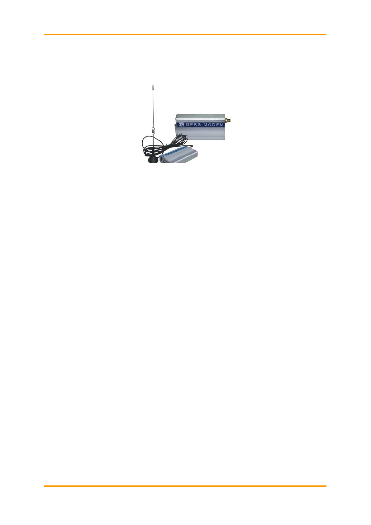
GPRS Wireless Modem
With RS-232 Interface
User Manual
Rev 2.0 12-12-2008
1
Page 2

Gprs/Gsm wireless modem with RS232 interface
www.mobidata.com.cn
Contents
1. Chapter 1 – Product Description and Specifications ............................................ 1
1.1. Product Description ................................................................................. 1
1.2. Features................................................................................................... 1
1.3. Application Overview ............................................................................... 2
1.4. Safety....................................................................................................... 3
1.5. Specifications........................................................................................... 5
2. Chapter 2 – Activation and Installation................................................................. 7
2.1. Step 1 – Activate Your Wireless Account ................................................. 7
2.2. Step 2 – Insert the SIM Card into the Holder ........................................... 7
2.3. Step 3 – Install the Modem Driver............................................................ 8
3. Chapter 3 – Using Your Wireless Modem............................................................ 9
3.1. Phone Numbers for the Wireless Modem................................................ 9
3.2. Examples of Useful A T Commands.......................................................... 9
3.3. Internet Access...................................................................................... 12
4. Chapter 4 – Troubleshooting and Frequently Asked Questions......................... 16
4.1. Troubleshooting Examples..................................................................... 16
4.2. Frequently Asked Questions.................................................................. 16
Rev 2.0 12-12-2008
2
Page 3
Gprs/Gsm wireless modem with RS232 interface
www.mobidata.com.cn
1. CHAPTER 1 – PRODUCT DESCRIPTION AND SPECIFICATIONS
1.1. Product Description
The GPRS modem is an external data/fax/voice wireless modem. It also supports mobile originated short message
service (SMS) and mobile-terminated SMS. It offers standards-based multi-band GPRS Class 10 performance.
This ready-to-deploy, standalone modem allows developers to add wireless commun ication to products with a
minimum of development time and expense. The GRPS Wireless Modem is based on industrystandard open
interfaces, is fully type approved, and can be desktop or panel mounted.
Models:
MTCBA-G-F1 is the 900/1800 MHz GPRS modem (RS-232)
MTCBA-G-F2 is the 850/1900 MHz GPRS modem (RS-232)
Other Product Codes:
NAM is the model for US and Canada
GB/IE is the model for Great Britain and Ireland
Euro/ROW is the model for Europe and the rest of the world
About Documentation:
Inc. reserves the right to revise this publication and to make changes from time to time in the content hereof
without obligation of , Inc., to notify any person or organization of such revisions or changes. Check ’s Web site for
current versions of our product documentation.
1.2. Features
• GPRS Class 10 operation
• Dual-band 850/1900 or 900/1800 GSM/GPRS
• GSM Class 1 and Class 2 Group 3 FAX
• Desktop or panel mounting
• Short Message Services including text and PDU, point-to-point, cell and broadcast.
• 14.4K GSM circuit switched data
• SMA antenna connector and SIM socket
• Serial interface supports DTE speeds to 115.2K
• AT command compatible
• MNP2 V.42bis data compression
• Numerous LEDs provide operational status
• ME + SIM phone book management
• Fixed dialing number
• SIM Toolkit Class 2
• SIM, network and service provider locks
• Real time clock
• Alarm management
• UCS2 character set management
• Packet data up to 85K bps
• Embedded TCP/IP stack
• Circuit-switched data (GSM) up to 14.4K bps transparent and nontransparent
Rev 2.0 12-12-2008
Page 4
Gprs/Gsm wireless modem with RS232 interface
www.mobidata.com.cn
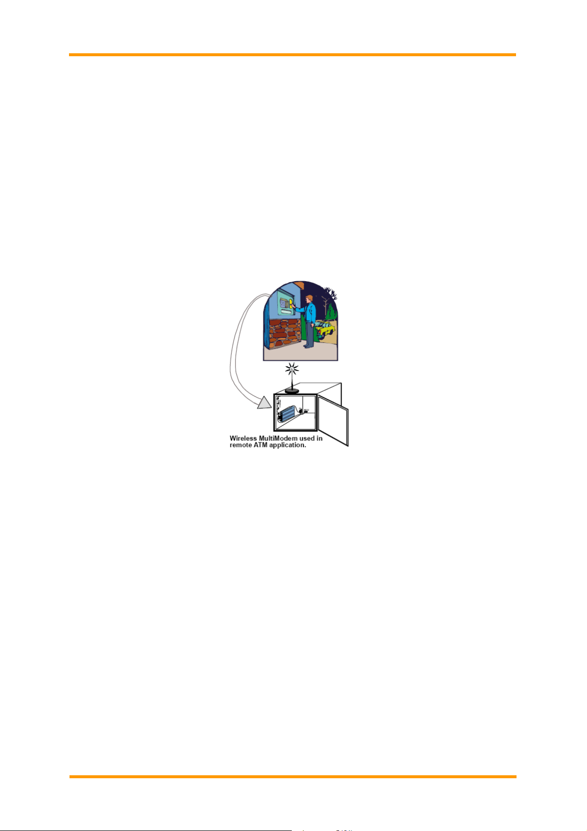
1.3. Application Overview
Application Types
With circuit switched data rates up to 14.4K bps, the GRPS Wireless Modem is targeted at applications that
periodically need to send or receive data over a wireless network. It is an ideal solution for:
Appliances
ATM Terminals
Automotive
Data Collection
Gas Pumps
Industrial and Medical Remote Monitoring Systems
Remote Diagnostics
Remote Metering
Security Systems
Vending/Gaming Machines
Devices required wireless connectivity.
Note: The Wireless Multi-Modem must be mounted with at least 8 inches (20 cm) of clearance from the human
body.
Benefits/Features in Applications
Short Developing Time
The GRPS Wireless Modem can make your existing and next generated device, machine, or system,
communication-ready without requiring any hardware changes to its design. It actually provides faster
time-to-market because it relieves the burden and expense of obtaining network and RF approvals. This complete,
ready-to-deploy wireless modem allows you to enha nce your
Product while you focus on developing its core features.
Voice Features
The GRPS provides telephony and Dual Tone Multi Frequency (DT MF) functional ity. It also allows for emergenc y
calls as well as echo cancellation and noise reduction (option), and full rate, enhanced Full Rate and Half Rate
(FR/EFR/HR).
Short Message Services (SMS)
The GRPS Wireless Modem offers SMS features such as text and PDU, point-to-point (MT/MO) and cell
broadcast.
Compatible Supplementary Services
The GRPS Wireless Modem is compatible with supplementary services such as call forwarding, call barring,
multiparty, call waiting and call hold, calling line identification, advice of charge, USSD, closed user group and
explicit call transfer.
Management Features
The GRPS Wireless Modem provides advanced management features inclu ding phone book management, fixed
dialing number, and real time clock and alarm management.
Industry-standard Modem Commands
The GRPS Wireless Modem provides industry-standard AT-style commands for ease of integration into your
existing software application.
Industrial Chassis
The GRPS Wireless Modem is packaged in a rugged, water resistant, industrial chassis. The chassis has an
RS-232 interface connector and a permanent screw type power connector. It also has an SMA antenna connector.
The chassis can be side-mounted on a panel or top-mounted on a desktop or other surface. A set of LEDs
Rev 2.0 12-12-2008
2
Page 5

Gprs/Gsm wireless modem with RS232 interface
www.mobidata.com.cn
indicates the modem’s operational status.
Packet-Switched Data
The GRPS Wireless Modem supports GPRS Class 10 packet-switched cellular data. This enables m obil e Internet
functionality by allowing inter-working between the existing Internet and the cellular network at speed s up to 85K
bps. Any service that is used over the fixed Internet today – File T ransfer Protocol (FTP), web browsing, chat,
e-mail, and telnet -- is available over the cellular network, as well. The Multi-Modem GRPS supports PBCCH and
coding schemes CS1 to CS4, and is compliant with SMG31bis.
Circuit-Switched Data (CSD)
The GRPS Wireless Modem also supports GSM circuit-switched cellular data conn ections. Circuit-switched data
connections support speeds up to 14.4K bps, Class 1 and Class 2 Group 3 fax, as well as MNP2 V.42bis
compression. CSD cellular wireless connections are ideal for applications that require a quick wireless
replacement of an existing point-to-point analog dial-up connection.
They integrate seamlessly with your current application requiring little infrastructure change.
Internet-Enabled
The GRPS Wireless Modem includes an embedded TCP/IP protocol stack to bring Internet connectivity to any
device. Using the embedded Internet protocols and the wireless connection to an IP network, it sends and receives
data over the Internet. It can also serve a single web page in response to a web browser request.
1.4. Safety
General Safety
The modem is designed for and intended to be used in fixed and mobile app lications. “Fixed” means that the
device is physically secured at one location and is not able to be easily moved to another location. “Mobile” means
that the device is designed to be used in other than fixed locations.
Caution: Maintain a separation distance of at least 20 cm (8 inches) is normally maintained between the
transmitter’s antenna and the body of the user or nearby persons. The Modem is not designed for or intended to be
used in portable applications within 20 cm. (8 inches) of the body of the user.
RF Interference Issues
It is important to follow any special regulations regarding the use of radio equipment due in particular to the
possibility of radio frequency, RF, interference. Please follow the safety advice given belo w carefully.
• Switch OFF your Wireless Multi-Modem when in an aircraft. The use of cellular telephones in an aircraft may
endanger the operation of the aircraft, disrupt the cellular network and is illegal. Failure to observe this instruction
may lead to suspension or denial of cellular telephone services to the offender, or legal action or both.
• Switch OFF your Wireless Multi-Modem when around gasoline or diesel-fuel pumps and before filling your vehicle
with fuel.
• Switch OFF your Wireless Multi-Modem in hospitals and any other place where medical equi pment may be in
use.
• Respect restrictions on the use of radio equipment in fuel dep ots, chemical plants or where blasting operations
are in progress.
• There may be a hazard associated with the operation of your Wireless Multi-Modem close to inadequately
protected personal medical devices such as hearing aids and pacemakers. Consult the manufacturers of the
medical device to determine if it is adequately protected.
• Operation of your Wireless Multi-Modem close to other electronic equipment may also cause interference if t he
equipment is inadequately protected. Observe any warning signs and ma nufacturers’ recommendations.
Safety Instructions for Hazardous Locations
• The modems are open devices intended for installation in an ultimate enclosure suitable for the intended
application.
• All wiring must be in accordance with wiring methods of Article 501.4B of the Natio nal Electrical Cod e, NFPA 70
or as specified in section 18-152 of the China Electrical Code for installation within China and in acco rdance with
the authority having jurisdiction.
• “WARNING - EXPLOSION HAZARD - Substitution of Components may Impair Suitability for Class I Division 2”.
• “WARNING - EXPLOSION HAZARD - Do not Disconnect Equipment Unless Power has been switched off or the
area is known to be Non-Hazardous”.
• “WARNING - EXPLOSION HAZARD - Do not replace the Fuse Unless Power has been switched off or the area is
known to be Non-Hazardous”.
• “WARNING - Do not install or remove the SIM card Unless Power has been switched off or the area is known to
be Non-Hazardous”.
Vehicle Safety
• Do not use your Multi-Modem while driving.
• Respect national regulations on the use of cellular telephones in vehicles. Road safety always comes first.
• If incorrectly installed in a vehicle, the operation of Wireless Multi-Modem telephone could interfere with the
correct functioning of vehicle electronics. To avoid such problems, be sure that qualified personnel have performed
the installation. Verification of the protection of vehicle electronics should be part of the installation.
• The use of an alert device to operate a vehicle’s lights or horn on public roads is not permitted.
Maintenance of Your Modem
Rev 2.0 12-12-2008
3
Page 6

Gprs/Gsm wireless modem with RS232 interface
www.mobidata.com.cn
Your Wireless Multi-Modem is the product of advanced engineering, design, a nd craftsmanship and should be
treated with care. The suggestions below will help you to enjoy this product for many years.
• Do not expose the Wireless Multi-Modem to any extreme environment where the temperature is above 50ºC or
humidity is above 90% non-condensing.
• Do not attempt to disassemble the Wireless Multi-Modem. There are no user serviceable parts inside.
• Do not expose the Wireless Multi-Modem to water, rain, or spilled beverages. It is not waterproof.
• Do not place the Wireless Multi-Modem alongside computer discs, credit or travel cards, or other magnetic media.
The phone may affect the information contained on discs or cards.
• In the unlikely event of a fault in the Wireless Multi-Modem, contact Tech Support.
Rev 2.0 12-12-2008
4
Page 7

Gprs/Gsm wireless modem with RS232 interface
www.mobidata.com.cn
Your Responsibility
This Wireless Multi-Modem is your responsibility. Please treat it with care respecting all local regulations. It is not a
toy.
Therefore, keep it in a safe place at all times and out of the reach of children.
Try to remember your Unlock and PIN codes. Become familiar with and use the security features to block
unauthorized use and theft.
Package Contents
Single Package (one unit) Bundled Package (multiple units)
1 modem
1 mounting bracket
1 fused DC power cable
1 Quick Start Guide
Each individual package in the bundle includes the following:
1 modem
1 mounting bracket
1 RS232 cable (9-to-9 pin)
1 antenna
1 power supply (type depends on regional in which it will be used)
4 adhesive-backed rubber feet for table-top mounting
1 Multi-Modem CD
1 Quick Start Guide
Part to be supplied by Wireless Service Provider
Subscriber Identity Module (SIM) configuration chip. The SIM contains information specific to your wireless
account and its features.
Parts to be supplied by End User
• mounting screws (screw shaft diameter = 1mm” max.)
• antenna (Basic Package)
1.5. Specifications
Power Requirements 5V to 37V;400mA Average
Mechanical Dimensions &
Weight
Connectors & Fasteners Antenna Connection type: SMA jack
Operating Temperatures -20° to +55°C
Humidity Relative humidity 20% to 90% non-condensing
Functions – GSM Modes
Mode Description
Standard Dual Band Extended GSM 900 MHz Class 4 (2W) and GSM 1800/1900 MHz Class 1 (1W)
Interface Serial interface RS-232. V.24/V.28 Auto-baud function.
SMS Mobile Originated (MO) and Mobile Terminated (MT) SMS Mode Text & PDU point to point. Cell
broadcast in accordance with GSM 07.05.
Data Data circuit asynchronous, transparent, non-transparent up to 14,400 bits Mode 3.1 KHz (PSTN) and
V110 (ISDN).
Fax 2400/4800/7200/9600 bps
Fax GSM Tele-service 62 in Transparent Mode.
Class 1 and Class 2 Group 3 compatible.
GPRS Class 10. Coding schemes: CS1 to CS4.
Electrical Characteristics
Electrical Characteristics
Switching the GSM modem
on/off
Voltage Range Voltage range : 5 to 37V DC
Over voltage and Under
voltage
Input/output electrical characteristics for external connections
Parameters GSM/GPRS
94mm*54*25;100g
Serial Connector: 9-pin RS232 SUB D female
Pins: RS232 link, audio link, BOOT, RESET
SIM receptacle: (standard)
The device is permanently powered (when connected to the power supply).
GND : 0V
Correct operation of the Wireless Multi-Modem in communication mode is
not guaranteed if input voltage falls below 5V.
850/900
GSM/GPRS
1800/1900
Unit
Rev 2.0 12-12-2008
5
Page 8

Gprs/Gsm wireless modem with RS232 interface
www.mobidata.com.cn
Input Supply Voltage
Input peak supply current in
comm. mode at P
Input average supply current in
comm. mode at P
Input average supply current in
idle mode
Antenna/RF Specifications
GSM850 EGSM900
Frequency RX Frequency RX
Frequency TX
RF Power Stand
Impedance
VSWR
Typical Radiated Gain
GSM1800 EGSM1900
Frequency RX
Frequency TX
RF Power Stand
Impedance
VSWR
Typical Radiated Gain
max
max
824 to 849 MHz 880 to 915 MHz
2W at 12.5% duty cycle 2W at 12.5% duty cycle
50 ohms
<2
0 dBi on azimuth plane
1805 to 1880 MHz 1930 to 1990 MHz
1710 to 1785 MHz 1850 to 1910 MHz
1W at 12.5% duty cycle 1W at 12.5% duty cycle
50 ohms
<2
0 dBi on azimuth plane
Typ. Typ.
5 12 37 5 12 37 V
1 0.4
360 150 75 300 125 70
30 10 10 30 10 10
0.
1 0.4 0.2
2
925 to 960 MHz
A
mA
mA
Interfaces
The Wireless Multi-Modem has several interfaces:
LED function indicating operating status
External antenna (via SMA connector)
Serial and control link (via 9 pins SUB D)
SIM card holder
LEDs
LED Indicators
TD
RD
CD
LS
TR
PWR
Transmit Data. Lit when modem is transmitting data.
Receive Data. Lit when modem is receiving data.
Carrier Detect. Lit when data connection has been established.
Line Status.
Continuous “on” state indicates that the wireless modem is not
registered on the network.
Flashing state indicates registration on network.
Off state. Modem is off (not ready) or in download mode.
Terminal Ready. Commonly called “Data Terminal Ready.” This is a
readiness signal from the PC.
Power. Indicates presence of DC power when lit.
RS232 9-Pin Connector Pinout
AT Command Information
AT commands for the GPRS wireless modem are published in a separate Reference Guide included on the
GPRS CD.
Rev 2.0 12-12-2008
6
Page 9

Gprs/Gsm wireless modem with RS232 interface
www.mobidata.com.cn
2. CHAPTER 2 – ACTIVATION AND INSTALLATION
2.1. Step 1 – Activate Your Wireless Account
Phone Numbers for the Wireless Modem
Every wireless modem will have its own unique phone number. The phone number may simply be given to you
by your wireless service provider or it may be on the SIM card or both. Wireless provider implementations may
vary.
2.2. Step 2 – Insert the SIM Card into the Holder
The wireless Multi-Modem requires the power supply connection to begin o peration. It also requires a SIM card
SIM Card (Subscriber Identity Module) to operate on a GSM network. To install the modem, do the following:
Insert the SIM card into the holder.
1.
2. Verify that the SIM card fits into the holder properly and then replace the cover.
Antenna
Connect a suitable antenna to the SMA connector (see antenna specificat ions on page 9).
Power
Supply DC Power(5——37V)
Rev 2.0 12-12-2008
7
Page 10

Gprs/Gsm wireless modem with RS232 interface
www.mobidata.com.cn
2.3. Step 3 – Install the Modem Driver
RS232 is the industrial standard interface, when you connect the modem with PC, it will be recognized, and t he
device is compatible.
Rev 2.0 12-12-2008
8
Page 11

Gprs/Gsm wireless modem with RS232 interface
www.mobidata.com.cn
3. CHAPTER 3 – USING YOUR WIRELESS MODEM
3.1. Phone Numbers for the Wireless Modem
• Every wireless modem will have its own unique phone number.
• The phone number may simply be given to you by your wireless servic e provider or it may be o n the SIM card or
both. Wireless provider implementations may vary.
3.2. Examples of Useful AT Commands
About HyperTerminal
In order to verify signal strength and roaming status, you must use a terminal application such as HyperTerminal.
To open this program in Windows XP or Windows 2003, go to Start > All Programs > Accessories >
Communications
> HyperTerminal. Other Windows operating systems have similar paths to HyperTerminal. See your s ystem’s
online
Help if you cannot find it.
A Note About AT Commands
AT commands can be used to operate, configure, and query your modem. A reference guide to the GPRS
commands is included on the Multi-Modem CD
The following two commands let you query signal strength and roaming status.
Verifying Signal Strength
Using HyperTerminal, type AT+CSQ
The modem responds with the received signal strength (rssi).
The modem responds with the received signal strength (rssi) and the channel bit error rate (ber).
RSSI ranges from 0 to 31.
Checking the Modem’s Identity
Use the ATI command (Note: This command is illustrated using the capital letter i after AT)
• Type ATI0 (Note: The command ends in a zero)
The manufacturing data displays. For example: Wavecom Modem Multiband G850 1900
• Type ATI3
The software version displays. For example: 651_09gg...
• Type ATI6
Displays modem data features. For example: data rates, data modes, fax classes.
Establishing a Voice Call
• Enter PIN Code (if required by your wireless provider)
Type AT+CPIN=1234
Responses: OK (PIN Code accepted)
+CME ERROR: 16 (Incorrect PIN Code)
+CME ERROR: 3 (PIN already entered [with +CMEE: 1 mode])
• Initiate a voice call
Type ATD1234; (Note: Don’t forget the semicolon “;” at the end. This stands for voice calls)
Responses: OK (Communication established)
CME ERROR: 11 (PIN Code not entered [with +CMEE: 1 mode])
CME ERROR: 3 (Operation not allowed)
Rev 2.0 12-12-2008
9
Page 12

Gprs/Gsm wireless modem with RS232 interface
www.mobidata.com.cn
• Initiate an emergency call
Type ATD112; (Note: Don’t forget the semicolon “;” at the end. This stands for voice calls)
Responses: OK
• Hang up
Type ATH
Responses: OK
Establishing a Circuit-Switched Data (CSD) Connection
A Circuit-Switched Data Connection makes the wireless modem work similar to a regular analog modem. You
must have CSD service in order to make a CSD call.
Note: Your wireless service provider charges airtime usage for thes connections.
Establish a Connection: Using HyperTerminal or a terminal application, you can establish a CSD connection by
entering the following command: ATD<phone number>
Notes:
• The phone number you are calling is entered between the displayed
brackets. Do not type additional brackets. For example, type only ATD
86110611. 86110611 is typed between the brackets.
• This command tells the modem to inform the wireless network that you are initiating a CSD modem call. If you are
dialing to another modem, the remote modem should answer and a connection bet ween the two modems will be
established. If you include a semi-colon (;) at the end of the dialing string, the modem will instead initiate a Voice
call to the phone number dialed.
Answering a Circuit-Switched Data (CSD) Connection
A Circuit-Switched Data Connection makes the wireless modem work similar to a regular analog modem. You
must have CSD service in order to answer a CSD call.
There are three phone numbers for GSM: the voice number, the data number, and the fax number. All are provided
by the carrier. To answer a call:
Establish A Connection: Call into the modem by dialing th e data number provided by your carrier.
Answer a Call: When you see the RING responses on the terminal screen, enter ATA <cr> to answer the call.
Set Auto-Answer: Enter ATS0=x
This sets the modem to auto-answer. The call will be answered after the numb er of rings entered. x stand for the
number rings.
Then call into the number provided to you by the carrier.
Disconnect: Type: +++
Wait about one second to see an OK response.
Then type: ATH
Using Short Message Services (SMS)
Send a Short Message to a Specified Number.
Type AT+CMGS="86110611" <press Enter>
Then type your message: Please call me soon. <press ctrl Z>
The modem may respond with +CMGS:<mr> OK
Write a Message to Memory.
You can store a message to send it at a later date.
Type AT+CMGW="86110611" <press Enter>
Type the message. <press ctrl Z>
The modem may respond with +CMGW: 4 OK (The message is stored in the index as message 4.)
Send a Message from Storage.
Type AT+CMSS=x,"86110611" <press Enter>
The modem may respond with +CMSS: 1 OK (The transmission is successful. One SMS message is sent.)
Note: The x represents an index location.
View a List of Stored Messages.
Type AT+CMGL=x <press Enter>
For x, substitute one of the following:
"REC UNREAD" Shows received unread messages.
"REC READ" Shows received read messages.
"STO UNSENT" Shows stored unsent messages.
"STO SENT" Shows stored sent messages.
"ALL" Shows messages.
The modem will respond AT+CMGL: 1,"REC UNREAD","86110611",1...
The modem will continue until all UNREAD messages, numbers, and index numb er are listed.
Read a Stored Message.
Type AT+CMGR=x <press Enter>
The modem may respond with +CMGR: "REC READ", "86110611” ...
Note: The x represents an index location.
Delete a Stored Message.
Rev 2.0 12-12-2008
10
Page 13

Gprs/Gsm wireless modem with RS232 interface
www.mobidata.com.cn
Type AT+CMGD=x,n <press Enter>
If you want to delete one message at a time, do not enter a value for n.
For n, substitute one of the following:
0 Delete message at location <include the index number>
1 Delete all READ messages.
2 Delete all READ and SENT messages.
3 Delete all READ, SENT, and UNSENT messages.
4 Delete ALL messages.
The modem will respond OK.
Note: The x represents an index location. The n stands for the type of messages to delete.
SMS Examples
Send Example
Send an SMS message to another SMS compatible device
at+cmgf=1 (set to text mode)
OK
at+cpms="SM","SM" (set memory storage when writing and sending SMS messages)
+CPMS: 0,50,0,50
OK
at+cmgs="86110631" (send message to the number specified in qu otes)
> TEST message ONE. ( Type message after the > symbol and hit <CTRL + Z> to send the message)+CMGS: 52
OK
Receive Examples
Receive Example 1: Receive SMS messages in text mode by saving to SIM memory – Notification via
+CMTI unsolicited response code:
at+cmgf=1 (set to text mode)
OK
at+csms=0 (set to Phase 1)
+CSMS: 1, 1, 1
OK
at+cnmi=2,1,0,0,0 (set to display +CMTI indication when SMS is received)
OK
at+cpms="SM","SM" (set the read and write storage of SMS to SIM)
+CPMS: 0, 50,0,50
OK
+CMTI: "SM", 1 (indication that message was received and stored to SIM location 1)
at+cmgr=1 (read message stored in location 1)
+CMGR: "REC UNREAD","+13537491551",,"06/03/17,13:55:22+00"
TEST1
OK
at+cmgd=1 (delete message that is stored in location 1)
OK
Receive Example 2: Receive SMS message in text mode by directly routing the received message to the TE
through the serial port using Phase 2:
at+cmgf=1 (set to text mode)
OK
at+csms=0 (set to Phase 2)
Rev 2.0 12-12-2008
11
Page 14

Gprs/Gsm wireless modem with RS232 interface
www.mobidata.com.cn
+CSMS: 1, 1, 1
OK
at+cnmi=2,2,0,0,0 (set to receive SMS and route directly to TE)
OK
+CMT: "+13537491551",”06/03/17, 13:59:18+00" (message received and directly routed to TE)
TEST2
Receive Example 3: Receive SMS message in text mode by directly routing the received message to the TE
through the serial port using Phase 2+:
at+cmgf=1 (set to text mode)
OK
at+csms=1 (set to Phase 2+)
+CSMS: 1, 1, 1
OK
at+cnmi=2,2,0,0,0 (set to receive SMS and route directly to TE)
OK
+CMT: "+13537491551",”06/03/17, 14:01:17+00" (message received and directly routed to TE)
TEST3
+cnma (acknowledge that message has been received)
OK
3.3. Internet Access
Internet access can be setup in Windows Dial-Up Networking (DUN) of the computer that the wireless modem is
serving. Setup procedures will vary according to the type of wireless service provider used. To access Dial-Up
Networking on your PC, go to Start > Accessories >COMMUNICATION> Network Connections.
• For GSM-without-GPRS, a circuit-switched data connection is used. The user can set up DUN to make a
conventional V.32 modem connection to any terminating modem at the other end. The phon e number specified in
DUN can be one supplied by the wireless service provider or another phone n umber related to a different dialup
modem service (e.g., a dialup modem service phone number from any commercial or private dialup network).
• For GSM-with-GPRS, a single DUN number is generally used by all of a wireless provider’s subscribers
throughout its area of coverage; regional, nationwide, continental, etc. Rather than being a literal pho ne directory
number, as in conventional DUN, this is a code that gives the modem Internet access.
Connecting to the GPRS Network for Internet Access
After you have inserted the SIM card and the modem is ready for use, you can establish an Internet connection
through a Windows dial-up session.
Note that your wireless provider will charge you for data usage.
Requirements
• One wireless GPRS modem
• The GPRS modem should have an active SIM card and must have GPRS services
• The modem must be getting a proper signal and be showing a network registration through the wireless
provider’s network
• A PC running Windows XP or 2003 with the GPRS drivers installed for your particular model
The following instructions are for Windows XP SP2 and Windows 2003 . Every PC may have slight differences
which may cause the instructions to be different. Use these instructions as a guide to help you understand what is
required to set up an Internet connection through your wireless service provider for all operating systems.
Note: Cellular providers provide Internet services as part of your service plan. recommends that if you plan o n
using large amounts of data, to sign up for an unlimited data service plan with your provider.
will not be responsible for an y ch arges on your cel lul ar bi ll. If you have any questions about billing, service plans,
service charges, etc., please contact your provider for more information.
Set the Access Point Name (APN) into the Modem’s Properties on Your PC
In order for your GPRS wireless modem to connect to your provider’s network, you must tell the modem the
Access Point Name (APN) to which it will connect. The APN is a server name that your account is setup on with
your provider. Your APN will be given to you by your provider.
Steps for Setting the APN
1. Start by clicking on Start and then clicking on Control Panel.
2. In the Control Panel, double-click on Phone and Modem Options.
3. The Phone and Modem Options window appears. Click on the tab labeled Modems. Highlight the wireless
modem listed in the table and then click on Properties.
Rev 2.0 12-12-2008
12
Page 15

Gprs/Gsm wireless modem with RS232 interface
www.mobidata.com.cn
4. A Properties window for your modem will display. Click on the Advanced tab and you should see an Extra
Settings box. In the Extra initialization commands text box, type:
AT+CGDCONT=1,“IP”,“<APN>”
For <APN>, you need to type in the correct APN for your account. For example:
AT+CGDCONT=1,“IP”,“CMNET”
Click OK to close the modem Properties window. Then click OK to close the Phone and Modem Options window.
Create a connection to access to internet
Do as the follows:
Click Start, and then go to control panel
Go to network and internet connections, and click Network Connections
Create a new connection
Rev 2.0 12-12-2008
13
Page 16

Gprs/Gsm wireless modem with RS232 interface
www.mobidata.com.cn
Rev 2.0 12-12-2008
14
Page 17

Gprs/Gsm wireless modem with RS232 interface
www.mobidata.com.cn
The connection will now tell the modem to connect to your provider’s Internet service. Once connected, you should
see the connection status icon in your system tray at the bottom right-hand corner of your screen.
You should now be able to open Internet Explorer or any other browser of your preference to surf the Internet.
Disconnecting the Connection:
1. To disconnect the connection, right click on the connection icon i n your system tray at the bottom right-hand
corner of your screen.
2. Scroll up and click on Disconnect.
You should now be disconnect from the Internet.
Rev 2.0 12-12-2008
15
Page 18

Gprs/Gsm wireless modem with RS232 interface
www.mobidata.com.cn
4. CHAPTER 4 – TROUBLESHOOTING AND
FREQUENTLY ASKED QUESTIONS
4.1. Troubleshooting Examples
Before calling the Support, check to the following connections:
• The right antenna is connected to the modem
• The serial cable connection is correct
• The power is connected correctly and the power lights on the modem are on
• Verify your signal strength
• Verify your network registration
• Use the following situation examples to troubleshoot the modem not answering and the modem returning a No
Carrier message.
Situation A: The modem does not answer
If the Wireless Multi-Modem does not answer through the serial link upon an attempted transmission of data or
voice signals, see the table below for possible causes and solutions.
4.2. Frequently Asked Questions
Which providers can I use?
• One major providers is China-Mobile.
• We are China-Mobile approved.
Does this modem support High-Speed Circuit-Switched Data (HSCSD)?
• No, our GSM/GPRS modems do not support HSCSD.
The modem is answering, but seems to not be doing anything?
• The modem is answering in voice mode.
• If you are trying to make a data call, make sure the account has CSD service. You will also need the data number
(separate number from the main phone number that is provided by the provider).
I am trying to make a data connection by dialing from my wireless modem to an analog modem. Why does
the analog modem answer and send tones, but never connect?
• To make a data call you must use the ATD<number> command.
• Make sure the account has CSD service.
How do I make an Internet connection to my dial-up ISP?
• Make sure you have CSD service.
• Create a dial-up connection to the ISP’s access number, then us e your account username and password and
choose the wireless modem as the device.
How does faxing work?
• GPRS modems support Class 1 and Class 2 Group 3 faxing.
Rev 2.0 12-12-2008
16
Page 19

Gprs/Gsm wireless modem with RS232 interface
www.mobidata.com.cn
• You will need fax services setup on your account. You should receiv e a separate phone numb er for fax just like
voice and data, and you must call the fax number for the modem to receive a fax.
• You will also need fax software (we do not have working soft ware). WinFax Version 10 has been tested with
success.
I can’t make outgoing calls. I just receive a NO CARRIER response.
• Make sure the antenna is connected and SIM is inserted correctly.
• Check signal and registration: ‘AT+CSQ’ (10-31 is good), ‘AT+CREG?’ (0,1 is registered & 0,5 is roaming).
• Check NO CARRIER reason with ‘AT+CEER’. Look up error code in Reference Guide.
The modem will not answer.
• To have modem auto-answer, set modem with ‘ATS0=1’ and ‘AT&W’ to store the setting.
• Send ‘ATA’ to the modem once the RING is indicated on the terminal screen.
• You may need to set modem to ignore DTR, ‘AT&D0’, if you aren’t providing DTR.
I am trying to make a GPRS connection using a Windows dial-up session. It connects and then
immediately disconnects.
• Make sure the APN is configured in the modem correctly (The APN is provided by the provider).
• Check the APN with ‘AT+CGDCONT?’ To make sure it is correct.
• If no APN is inserted, then insert the correct APN using the command ‘AT+CGDCONT=1,“IP”,“CMNET”’with
HyperTerminal or add it into the “Extra Initialization Commands:” in the modem’s properties.
• Make sure the APN is correct for your account.
When I try to establish a GPRS connection using Windows dial-up I get an error: “Hardware Failure”.
• Check the modem to make sure it is installed and can be queried in the modem’s properties.
• Make sure the com port is not being held by another application. Look for the TR light indication. If it is on, most
likely another application is holding onto the port.
• Make sure the dial-up connections maximum speed matches the modem’s properties maximum port speed.
• Try rebooting the PC.
What is the maximum amount of characters I can use to send an SMS message?
• Supports up to 160 characters maximum.
• In PDU mode using 7-bit, the modem still supports 160 characters, but in 8-bit the modem will support only 70
characters.
After changing the +CNMI, +CSCA, or +CSMP command values, the modem doesn’t store th em.
• When changing these command values, you must use the +CSAS command to store the changes.
Rev 2.0 12-12-2008
17
 Loading...