

Page 1
Remote Access Device
Remote Access Server
with Integrated
WAN Devices
Model MTASR3-200
Quick Start Guide
Page 2

Quick Start Guide
S000334B Revision B
RASFinder Model MTASR3-200
This publication may not be reproduced, in whole or in part, without
prior expressed written permission from Multi-Tech Systems, Inc. All
rights reserved.
Copyright © 2004-07 by Multi-Tech Systems, Inc.
Multi-Tech Systems, Inc. makes no representations or warranties
with respect to the contents hereof and specifically disclaims any
implied warranties of merchantability or fitness for any particular
purpose. Furthermore, Multi-Tech Systems, Inc. reserves the right
to revise this publication and to make changes from time to time in
the content hereof without obligation of Multi-Tech Systems, Inc. to
notify any person or organization of such revisions or changes.
Record of Revisions
Revision Description
A Replaces printed Quick Start 82072506 (5/31/00).
(2/25/04) Manual revised to remove coax cable connection.
B Updated the Technical Support contact list and
(6/20/07) warranty statement and corrected the pin out for the
command cable. Updated CD image.
Patents
This Product is covered by one or more of the following U.S .
Patent Numbers:
5.452.289; 5.453.986
The Multi-Tech logo and RASFinder are trademarks of Multi-Tech
Systems, Inc. Windows is a registered trademark of Microsoft Corporation in the United States and other countries.
5.301.274; 5.309.562; 5.355.365; 5.355.653;
. Other Patents P ending.
TRADEMARK
Multi-Tech Systems, Inc.
2205 Woodale Drive
Mounds View, Minnesota 55112
(763) 785-3500 or (800) 328-9717
Fax 763-785-9874
Tech Support (800) 972-2439
Internet Address: http://www.multitech.com
Page 3

Contents
Introduction.................................................................................... 4
Related Documentation ................................................................. 4
Safety W arnings ............................................................................ 5
Unpacking your RASFinder ........................................................... 6
Cabling your RASFinder................................................................ 7
Installing Y our RASFinder Software............................................... 9
IP Routing Setup ................................................................... 14
Setting Up Your Remote User Database...................................... 17
Setting Up Remote Access Dial In User Server (RADIUS).......... 25
Final Routing Setup .................................................................... 28
iii
Page 4
RASFinder MTASR3-200 Quick Start Guide
Introduction
Welcome to Multi-Tech's RASFinder™, Model MTASR3-200, a
dial-up Remote Access Server (RAS) with three built-in 56K
modems for connecting telecommuters and mobile users to a
corporate LAN. A secondary capability of the RASFinder is LANto-LAN routing.
In its basic (remote access) function, the RASFinder supports up
to three concurrent dial-in sessions and IP or IPX remote access.
It also provides dial-out and faxing support for PC users on a
Novell IPX network.
The RASFinder features a 10BaseT port for local LAN connection,
a Command P o rt for configuration, and three internal V.90
modems*. System management is provided through the command
port using bundled Windows® based software which provides
easy-to-use configuration menus.
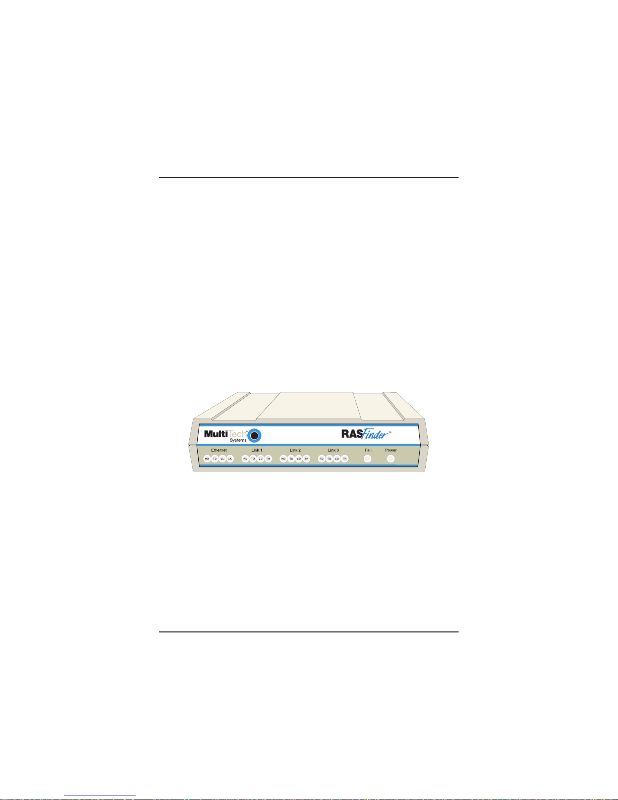
Remote Access Device
Figure 1. RASFinder Model MTASR3-200
Note: Although these modems are capable of 56K bps download
performance, line impairments, public telephone infrastructure and
other external technological factors currently prevent maximum 56
Kbps connections.
Related Documentation
The MTASR3-200 Quick Start Guide is intended to be used by
qualified systems administrators and network managers. This
quick start guide provides the necessary information for a qualified
person to unpack, cable, load software , and configure the unit for
proper operation.
4
Page 5

Introduction
Safety Warnings
1. Never install phone wiring during a lightning storm.
2. Never install phone jacks in wet locations unless
the jack is specifically designed for wet locations.
3.This product is to be used with UL and cUL listed computers.
4. Never touch uninsulated phone wires or terminals unless
the phone line has been disconnected at the network
interface.
5. Use caution when installing or modifying phone lines.
6. Avoid using a phone (other than a cordless type) during an
electrical storm. There may be a remote risk of electrical
shock from lightning.
7. Do not use the phone to report a gas leak in the vicinity of
the leak.
8. To reduce the risk of fire, use only No. 26 A WG or larger
Telecommunication line cord.
5
Page 6
RASFinder MTASR3-200 Quick Start Guide
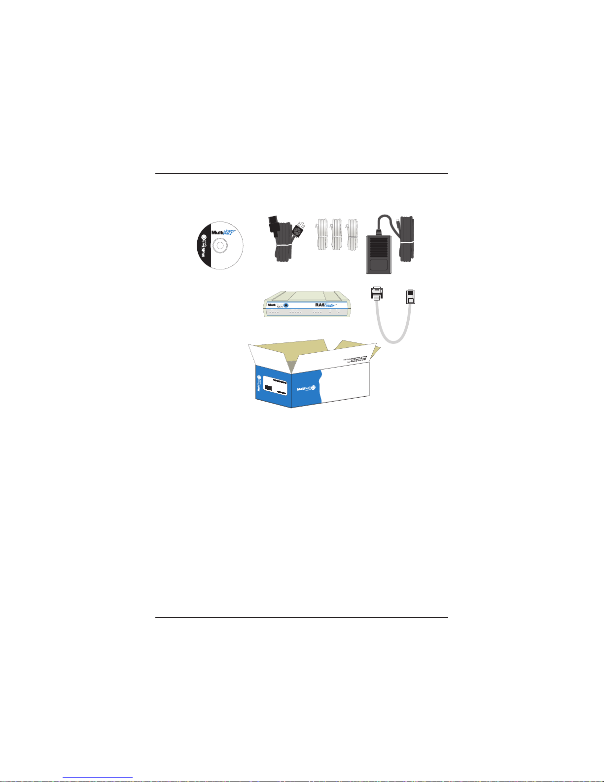
Unpacking your RASFinder
Remove all items from the box. See Figure 2.
200
Voice/Fax over IP Networks
www.multitech.com
Remote Access Device
LK
CL
TD
RD
M
A
D
E
I
N
U
.S
.A
RD TD CD NS DS RD TD CD
Remote Access Device
V35
MADE IN U.S.A
Figure 2. Unpacking Your RASFinder
6
Page 7
Cabling
Cabling your RASFinder
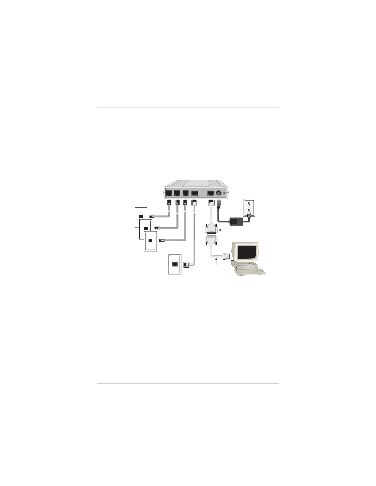
Cabling your RASFinder involves making the proper WAN,
Ethernet, Command Port, and Power connections. Figure 3 sho ws
the back panel connectors and the associated cable connections.
TThe following procedure provides step-b y-step instr uctions for
connecting the cables to your RASFinder.
WAN Connections
Ethernet Connection
LINK3 LINK2 LINK1 ETHERNET COMMAND POWER
10BASET
10BASE2
User-Supplied Cable
DB25 (male) to
DB9 (female)
ON
OFF
Command Cable
(supplied)
Power Connection
Figure 3. Cable Connections
1. Connect the RASFinder to a PC using the short RJ-45 to
DB9 (female) cable provided with your unit. Plug the RJ-45
end of the cable into the Command Port of the RASFinder
and the other end into the PC's serial port. See Figure 3.
2. Connect an RJ-45 (UTP) cable to the 10 BASE-T
connector on the back of the RASFinder. Connect the
other end of the cable to your LAN.
3. Connect one end of an RJ-11 cable to each of the LINK
Connectors on the RASFinder (labeled LINK 1,
LINK 2, and LINK 3) and connect the other end to the
phone jacks (as shown in Figure 3).
7
Page 8

RASFinder MTASR3-200 Quick Start Guide
4. Connect one end of the power supply to a live AC outlet
and connect the other end to the RASFinder as shown in
Figure 3. The power connector is a 6-pin circular DIN
connector.
5. Turn on power to the RASFinder by setting the backpanel
ON/OFF switch to the ON position. Wait for the Fail LED
on the RASFinder to go OFF before proceeding. This may
take a couple of minutes to go OFF.
At this time your RASFinder is completely cabled and
powered on.
Proceed to the next section to install the RASFinder software.
8
Page 9
Software
Installing Your RASFinder Software
The RASFinder software is set up to default to a Remote Access
Server (RAS) application. Within the RAS application, you can
configure the RASFinder to communicate with either a Radius
Server for centralized network security or a proprietary Remote
User Data base utility to establish your remote user profiles. You
can also configure the RASFinder as a router for LAN-to-LAN
routing.
The RASFinder CD-ROM contains your RASFinder software , this
Quick Start, and the User Guide. The RASFinder CD-ROM is autodetectable, and should start automatically when inserted into your
CD-ROM drive. After configuring your RASFinder, you can view
the User Guide by clicking the View Manuals icon and selecting
either the Quick Start or User Guide.
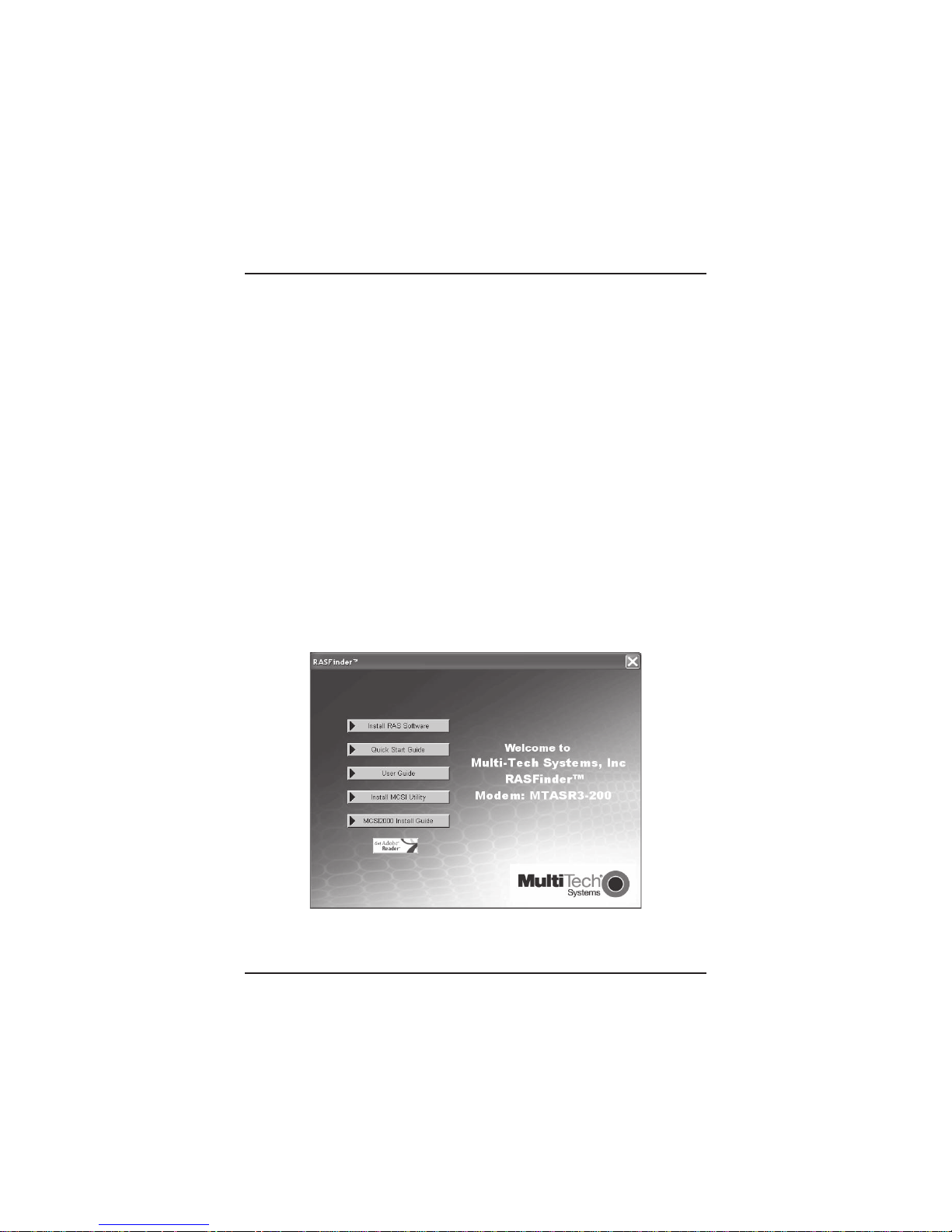
1. Insert the RASFinder CD-ROM into the CD-ROM drive on your
local PC. The CD-ROM should start automatically; however, it
may take 10 to 20 seconds for the RASFinder screen to
appear.
If the RASFinder Splash screen does not appear automatically, click My Computer, right-click the CD-ROM drive icon, then
click (Autorun or AutoPlay).
9
Page 10
RASFinder MTASR3-200 Quick Start Guide
2. When the RASFinder screen appears, click the Install RAS
Software button.
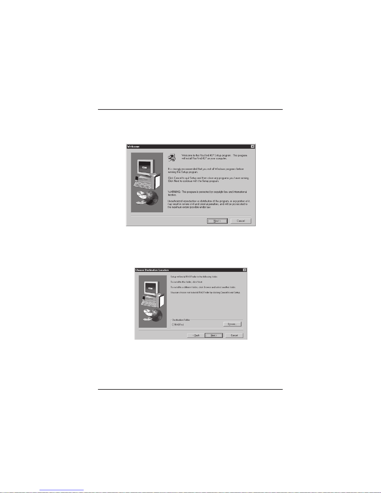
3. The welcome screen is displayed.
Press Enter or click Next> to continue.
4. The Choose Destination Location dialog box is displayed.
Follow the onscreen instructions to install your RASFinder
software.
You can either choose a different Destination Location for your
RASFinder software by clicking Browse, or select the default
destination by pressing Enter or clicking Next>.
It is recommended that you accept the default folder,
C:\RASFind.xxx
10
Page 11

Software
5. The Select Program Folder dialog box appears.
Press Enter or click Next> to continue
6. The software is loaded onto your PC, then the next dialog bo x
enables you to designate the COM port of the PC that is
cabled to the RASFinder. On the Select Port field, click the
down arrow and choose the COM port of your PC (COM1 -COM4) that is cabled to the RASFinder .
Click OK to continue.
11
Page 12

RASFinder MTASR3-200 Quick Start Guide
7. The Setup Complete dialog box is displayed.
Click Finish to continue.
8. The following message is displayed:
9. Click No to skip the upgrade process. The following message
appears:
10. Click Yes to download the default setup. (Clicking No prevents
you from setting up the defaults and downloading them to the
RASFinder; instead, you are returned to the desktop, where
12
Page 13

Software
you will see a window with shortcut icons for the various utility
programs in the software.)
11. The Default Parameters dialog box appears. This dialog box
allows you to enable or disable IPX routing, assign the router
name (required for IPX routing), establish the IP address and
mask for the LAN port, set up the remote addresses for the
WAN ports, and disable an y WAN ports not used.
12. If your network protocol is IPX, continue with the following step.
Howe ver, if your netwo rk protocol is IP, click the IPX Routing
Enable check box to
disable
IPX, then proceed to step 14.
IPX Routing Setup
13. Router Name: If this is the only RASFinder on your network,
you can use the default Router Name (MTROUTER); otherwise, you must assign a new Router Name in this field. The
Router Name can be any printable ASCII string of up to 8
characters (can be mixed uppercase and low ercase). The
RASFinder will use this name to advertise its service in the
IPX internetwork or as an AG Server, if that service is supported. Proceed to step 15.
13
Page 14

RASFinder MTASR3-200 Quick Start Guide
IP Routing Setup
14. For IP Routing, after you have enter your unique LAN address,
and the WAN Remote Addresses have to be in the same
network as the IP Address.
In the IP group, change the default LAN IP Address that is
assigned to your RASFinder’s LAN port. As you click OK,
sequential addresses will appear in the Remote address fields
for WAN1, 2, and 3. [See above , where the Ethernet IP Address was entered as 192.168.2.112, and the software applied
14
Page 15

Software
the next three sequential addresses (192.168.2.113,114, and
115) to WAN1, WAN2, and WAN3, respectively.]
15. The Checking Router dialog box is displayed with the message
Ready to Download Wizard Setup displayed. Clic k OK to
proceed
16. The Writing Setup dialog box (with the current date and the
file size in bytes) is displayed as the setup configuration is
written to the RASFinder.
17. Next, the Rebooting dialog box is displa yed.
18. Check to ensure that the Fail LED on the RASFinder goes Off
after the download is complete and the RASFinder is rebooted
(the Rebooting dialog box goes away). This may take several
minutes as the RASFinder reboots.
15
Page 16

RASFinder MTASR3-200 Quick Start Guide
19. You are returned to the Multi-Tech RASFinder AutoRun
screen where you can now install Acrobat Reader (by clicking
the Install Acrobat Reader icon) or View Manuals.
To view the User Guide or this Quick Start, click the View
Manuals icon.
20. If you are going to extablish your remote user profile database
using the proprietary Remote User Database utility, proceed to
the next section; if you are going to use a Radius server for
centralized network security, proceed to the section entitled,
Setting Up Remote Access Dail In User Server (RADIUS).
For Routing, proceed to the last section (Final Routing Setup)
to set up the RASFinder as a router.
16
Page 17

Software
Setting Up Your Remote User Database
The proprietary Remote User Data Base supports remote dial-in
users for user name, password, and port availability. Each dial-in
user needs an entry in this database. You can add remote users,
remove users, or edit information in the database.
1. From your desktop, click Start | Programs | RASFinder x.xx |
Remote User Data Base, or double-click the Remote User
Data Base icon in the RASFinder x.xx icon group window
(below).
2. An Accounting Info - Read screen appears briefly , then the
Users List dialog box is displayed.
Click Add and the Add Users dialog box is displayed.
17
Page 18

RASFinder MTASR3-200 Quick Start Guide
3. The Add Users dialog box is displayed.
4. Build your user database by filling in the following fields for
each user.
User Name
The User Name can have up to 39 characters. All printable
characters are permitted, except no b lanks are allow ed in
the user name. In dial-in and dial-out applications, the user
name is treated as a case insensitive string.
Password
The Password can have up to 10 characters. In places
where the password is used as a character string, it is
treated as a case insensitive string. Elsewhere (PPP’s
CHAP), it is treated as a case sensitive pattern.
Filter
This drop-down list enables you to select a given user by
means of the unique filter ID entry that was assigned to
that user on the Add/Edit Filters dialog box. The filter IDs
are unique alphanumeric Identifiers of up to 9 characters
in length.
Call Back
Clicking this check box enables the Call Back function.
Click ONLY this check box if the user can choose the
number where he is to be called. That remote user would
then use a standard PPP client or ASCII terminal dial-in.
18
Page 19

Remote User Data Base
To enable Call Back Security, check (activate) both the
Call Back option and the Call Back Security Enab led
option and fill in the call back number and delay fields.
Call Back Security Enabled
This parameter is of use in dial-in applications where the
user must alwa ys be called back at a specific phone
number. For call back security, the administrator assigns
the call back number and the call back delay.
Call Back Number
The call back number is active only if Call Back Security is
enabled (checked). This is the pre-assigned number where
the user will be called back. The user cannot choose the
callback number while at the remote location.
Note: The Call Back Number can be entered either with or
without dashes, the modem will simply ignore the dashes.
Call Back Delay
Call back delay is active only if callback security is
enabled. This entry specifies the duration (in seconds)
after which the user will be called back at the
administrator-assigned number .
Dial In Ports
The system administrator can enable (highlight) WAN
Ports 1,2, and/or 3 to be made availab le for dialing in to
the RASFinder.
Dial Out Ports
The system administrator can enable (highlight) WAN
Ports 1,2, and/or 3 to be made av ailable for dialing out
from the RASFinder.
Click the Rights button to assign user permissions f or the
remote user.
19
Page 20

RASFinder MTASR3-200 Quick Start Guide
5. The User Permissions dialog box is displayed.
6. Build your user permissions by filling in the following fields for
each remote user.
Auto Protocols
This group enables the system administrator to assign
either unrestricted LAN/intranet access or limited protocol
access. The following three options are provided.
None
This option (the default setting) gives the user unrestricted
access to the LAN/Intranet.
Telnet
This option allows Telnet sessions between the designated
server (defined by the Host IP Address field) and the
remote users. Telnet is an applications-level protocol
commonly found in IP-based networks that allow terminal
emulation at a remote workstation. If you select Telnet, you
must enter an IP address in the Host IP Address field. This
limits the user to only specific functions on the network.
RLogin
This option allows the RASFinder to be used as an RLogin
client for connecting to an RLogin Server (defined by the
20
Page 21

Remote User Data Base
Host IP Address field). RLogin is an application protocol
that provides a terminal interface between Unix hosts
using TCP/IP network protocol. Unlike Telnet, RLogin
assumes that the remote host is a Unix machine. If yo u
select RLogin, you are required to enter an IP address in
the Host IP Address field. This limits the user to only
specific functions on the network.
Host IP Address
Enter the IP Address for the Telnet or RLogin host
computer (server). The Host IP Address must be in dotteddecimal notation format.
Note: This field is only enabled (activ ated when either
Telnet or RLogin has been enabled.
Protocols
The Protocols group enables you to limit the remote user
to IP routing, IPX routing, or bridging (Spanning Tree); or a
combination of any two or all three routing protocols. The
default setting has all three protocols enabled.
User Service Types
The User Service Types group enables you to set the permissions
for the remote user entry being configured. The systems
administrator can enable or disable the following options to
customize the types of services for a particular remote user. By
default, all permissions are enabled. T o den y permissions to the
entry being configured, click (check) the box to the left of the
permission to disable the feature.
Outbound Permissions - gr ants dial-out rights to the
remote user.
Inbound Permissions - gr ants dial-in rights to the remote
user.
Framed Protocol Permissions - Grants the remote user
framed protocol rights (e.g., Framed Protocol - PPP).
When you enable (check) this option, the user becomes
an unrestricted user (i.e., both framed and unframed
protocols are allowed).
Telenet Permissions - grants the remote user Telnet file
21
Page 22

RASFinder MTASR3-200 Quick Start Guide
transfer rights.
RLogin Permissions - grants the remote user RLogin
server connection rights.
Time Limits
The Time Limits group enables the system administrator to
impose time-related restrictions to the entry being defined.
Time of the Day Logins
The User Permissions grid enables the administrator to
deny a remote user Internet access at certain times during
the week. This would be applicable when the administrator
wants to bring a system down for a particular reason and
doesn’t want users to access the Internet at that time.
By default, all time periods are color-filled with yellow
indicating that the remote user has permission to access
the Internet all the time. To deny permission for certain
periods of time, click all applicable yellow boxes over the
target time range to toggle them to red (Access Denied).
7. After each user is defined in the Add Users dialog box and all
the user parameters (Rights) are configured, click OK to
display the updated User List dialog box. Click Filters to add
filtering parameters for the remote user entry.
8. The Filters List dialog box is displayed.
Click the Add button.
22
Page 23

Remote User Data Base
9. The Add/Edit Filters dialog box is displayed.
10. Build your filtering parameters by filling in the following fields
for each remote user.
ID
This field requires a unique ID identifying the remote user.
The ID can be the name of a person, a work station, or a
remote user identified simply as “User 1”. The ID can be
up to 9 alphanumeric characters in length.
Default Action
This drop-down list enables you to select either filter or
forward. If you select filter, then the entry will be transmitted
with filtering properties. If you select f o r w ard, then the entry will
be transmitted without filtering properties. The default setting is
filter.
Filter Type
The Filter Type drop-down list enables you to select the filter
type. The filter types are either IP Address, Protocol, or Domain Name. The default setting for Filter Type is IP Address.
IP Address - If the filter type is IP Address, enter the IP
23
Page 24

RASFinder MTASR3-200 Quick Start Guide
Address of the remote user in dotted-decimal notation format.
Protocol - If you select Protocol as the filter type, the Add/
Edit Filters dialog box is displayed with Protocol and Port
drop-down lists active . Select either TCP or UDP from the
Protocol drop-down list and select either Telnet, FTP, or SFTP
from the Port drop-down list.
Domain Name - If you select Domain Name as the filter type,
the Add/Edit Filters dialog box is displayed with an active
Domain Name field. Enter the domain name consisting of a
sequence of names separated by periods (dots) followed by an
entension; e.g., “pictures.computers .com”. The domain name
can be up to 39 alphanumeric characters including periods.
Note: Current filter entries are displayed in the Existing Entries
window.
Click OK to add the remote user to the Filters List dialog bo x
and then click OK again to return to the User List dialog box.
11. Click Add User to continue adding users to your database.
12. After adding all current users to the database, click Down-
Load to write the user database to the RASFinder.
24
Page 25

Remote User Data Base
Setting Up Remote Access Dial In User Server (RADIUS)
RADIUS is an optional security feature that uses a single authentication server to centralize security on networks with large modem
pools, especially those with multiple communication servers.
1. From y our desktop, click Start | Programs | RASFinder
x,xx | RASFinder Configuration, or double-click the
RASFinder Configuration icon in the RASFinder x.xx
icon group window when it is displayed on your desktop .
2. The main menu (Router Setup) is display ed.
Click PPP / SLIP to continue.
3. The PPP Port Setup dialog box is displayed; click the
Advanced tab.
Click RADIUS to continue.
25
Page 26

RASFinder MTASR3-200 Quick Start Guide
4. The Radius Setup dialog box is displayed.
5. Click RADIUS Enable to enable Radius security services
for all ports on this RASFinder.
6. Click Accounting Enable if you want Radius to track
accounting information such as login and logout times,
bytes sent and received, etc.
7. Leave Allow Call if Security Server Down unchecked
(disabled) to prevent users from logging in if the security
servers are down.
8. Click Assign Remote Address Using RADIUS to enable
the Radius server to automatically assign the IP Address
of the RASFinder WAN port that the user will dial into.
9. Obtain the Shared Secret from the Radius network
26
Page 27

Radius
administrator. The shared Secret must be the same secret
that is used on the Radius server whose address is being
supplied for the Radius primary server address entry.
10. Obtain the Radius server address from the Radius
network administrator that will provide the security to the
RASFinder. The Radius server address is to be entered in
the Radius Primary Server Address field.
11. If additional servers are being used as backup servers,
obtain their address(es) from the Radius network
administrator and enter them in Backup Server group .
Enter the address of the first backup server in the Backup
Server Address 1 field. Enter the addresses of an y
additional backup servers in the Backup Server Address
2 and Backup Server Address 3 fields.
12. A set of default attribute values will be displayed in the
Attribute V alues group. These default values are used
with the Multi-Tech Radius Server. You do not have to
change these values if your RASFinder is communicating
with Multi-Tech’s Radius Server. However, if you are using
another vendor’s Radius Server to communicate with your
RASFinder, you will have to check with your Radius
Server network administrator to see how these attribute
values are set up, then change the default values to the
values used by that Radius server.
27
Page 28

RASFinder MTASR3-200 Quick Start Guide
Final Routing Setup
1. From your desktop, click Start | Programs | RASFinder
x.xx | RASFinder Configuration, or double-click the
RASFinder Configuration icon in the RASFinder x.xx
icon group window when it is displayed on your desktop.
2. The main menu (Router Setup) is display ed.
Click PPP / SLIP to continue.
3. The PPP Port Setup dialog box is displayed.
On the W AN 1 t ab, click Client or LAN in the Remote
28
Page 29

Routing Setup
Port Setup group in the bottom right corner; this enables
Client or LAN and disables the default, Client onl y.
Repeat this on the WAN 2 and WAN 3 tabs in turn.
4. If you are going to combine the three WAN ports together;
i.e., use a single IP address, check (enable) the MLPPP
option on the Advanced tab.
Note: When the dialog box “When a PPP port is Client-orLAN type:” appears, click the OK button each time the
dialog box appears. You are returned to the Main Menu.
29
Page 30

RASFinder MTASR3-200 Quick Start Guide
5. From the Main menu, clic k the IP button and the IP Port
Setup dialog bo x appears with the Ethernet tab activ e and
the Port Address displa ying your LAN IP Address.
Click the WAN 1 tab.
6. On the WAN 1 tab, change the Port Address and Remote
Address groups to be on separate networks from the
Ethernet LAN port.
If you enable the MLPPP option on the PPP Port Setup
30
Page 31

Routing Setup
dialog box, The IP addresses for all three WAN ports have
to be identical and the remote WAN port addresses have
to be within the same network and identical.
If you did not enable the MLPPP option, the WAN port
addresses have to be on a different network from the LAN
port address and have to be different from each other.
7. Click each of the WAN tabs and change the Port Address
group and Remote Address group to conform with the
settings for WAN 1.
8. Click OK to return to the Main menu.
9. From the Main menu, clic k the Do wnload Setup button to
write your configuration to the RASFinder . After your
configuration is written to the RASFinder, y ou are returned
to the Main menu. Your RASFinder is now configured for
LAN-to-LAN routing.
31
Page 32
S000334B
 Loading...