

Page 1

Page 2

Owner’s Manual
P/N 82034802Rev.C
Model MT64DSU
This publication may not be reproduced, in whole or in part, without prior
expressed written permission from Multi-Tech Systems, Inc. All rights
reserved.
Copyright © 1998 by Multi-Tech Systems, Inc.
Multi-Tech Systems, Inc. makes no representation or warranties with
respect to the contents hereof and specifically disclaims any implied
warranties of merchantability or fitness for any particular purpose.
Furthermore, Multi-Tech Systems, Inc. reserves the right to revise this
publication and to make changes from time to time in the content hereof
without obligation of Multi-Tech Systems, Inc. to notify any person or
organization of such revisions or changes.
Record of Revisions
Revision Description
B Manual revised. Additional information on the CompuServe/
(6/10/96) Internet forums; information on Multi-Tech's Fax-Back Service;
documentation of a new DIP-Switch Summary; editorial and
format changes throughout this manual.
C Manual revised. Reproduced using new Owner's Manual
(12/15/98) format. Made technical corrections and editing updates.
Removed all references to 2-wire connector.
TRADEMARKS
Multi-Tech and the Multi-Tech logo are trademarks of Multi-Tech Systems,
Inc.
DATAPHONE is a registered trademark of AT&T.
All brand and product names mentioned in this publication are trademarks
or registered trademarks of their respective companies.
Multi-Tech Systems, Inc.
2205 Woodale Drive
Mounds View, Minnesota 55112 U.S.A.
(612) 785-3500 or (800) 328-9717
U. S. FAX 612-785-9874
Fax-Back Service 612-717-5888
Technical Support (800) 972-2439
BBS (612) 785-3702 or (800) 392-2432
Internet Address: http://www.multitech.com
Page 3

Contents
Chapter 1 - Introduction and Description
Introduction ................................................................................ 6
About This Manual ..................................................................... 7
DSU Basic Functions ................................................................. 8
DSU Functions..................................................................... 8
CSU Functions..................................................................... 8
Front Panel Indicators ................................................................ 9
Back Panel ............................................................................... 10
Features ................................................................................... 11
Technical Specifications ........................................................... 12
Chapter 2 - Installation and Cabling
Introduction .............................................................................. 14
Unpacking ................................................................................ 14
Safety Warnings....................................................................... 14
Cabling Procedure ................................................................... 15
DIP Switch Settings.................................................................. 16
Chapter 3 - Testing
Diagnostic Tests ....................................................................... 22
DSU Loopback Test ................................................................. 22
Local Loopback Test................................................................. 23
Digital Loopback Test ............................................................... 24
Local Loopback Test With Test Pattern .................................... 25
Digital Loopback Test With Test Pattern Test ........................... 26
Remote Loopback Test............................................................. 27
Remote Loopback Test With Test Pattern Test......................... 28
DSU Back-to-Back Test............................................................ 29
iii
Page 4

Chapter 4 - Warranty, Service and
Tech Support
Introduction .............................................................................. 32
Limited Warranty ...................................................................... 32
On-line Warranty Registration.................................................. 32
Tech Support ............................................................................ 33
Recording MultiDSU64K Information ................................. 33
Service 34
The Multi-Tech BBS ................................................................. 34
To log on to the Multi-Tech BBS......................................... 35
To Download a file.............................................................. 35
About CompuServe.................................................................. 36
About the Internet..................................................................... 36
About the Multi-Tech Fax-Back Service ................................... 37
Appendixes
Appendix A - AT Commands and S-Registers.......................... 40
Appendix B - Application Examples.......................................... 51
Appendix C - Interface Signals and Connector Pinouts ........... 56
Appendix D - DIP-Switch Summary ......................................... 62
Appendix E - FCC Regulations for Telephone Line
Interconnection ............................................................... 63
Index
iv
Page 5

MultiDSU64K
Chapter 1 - Introduction and Description
Page 6
6
MT64DSU Owner's Manual
Introduction
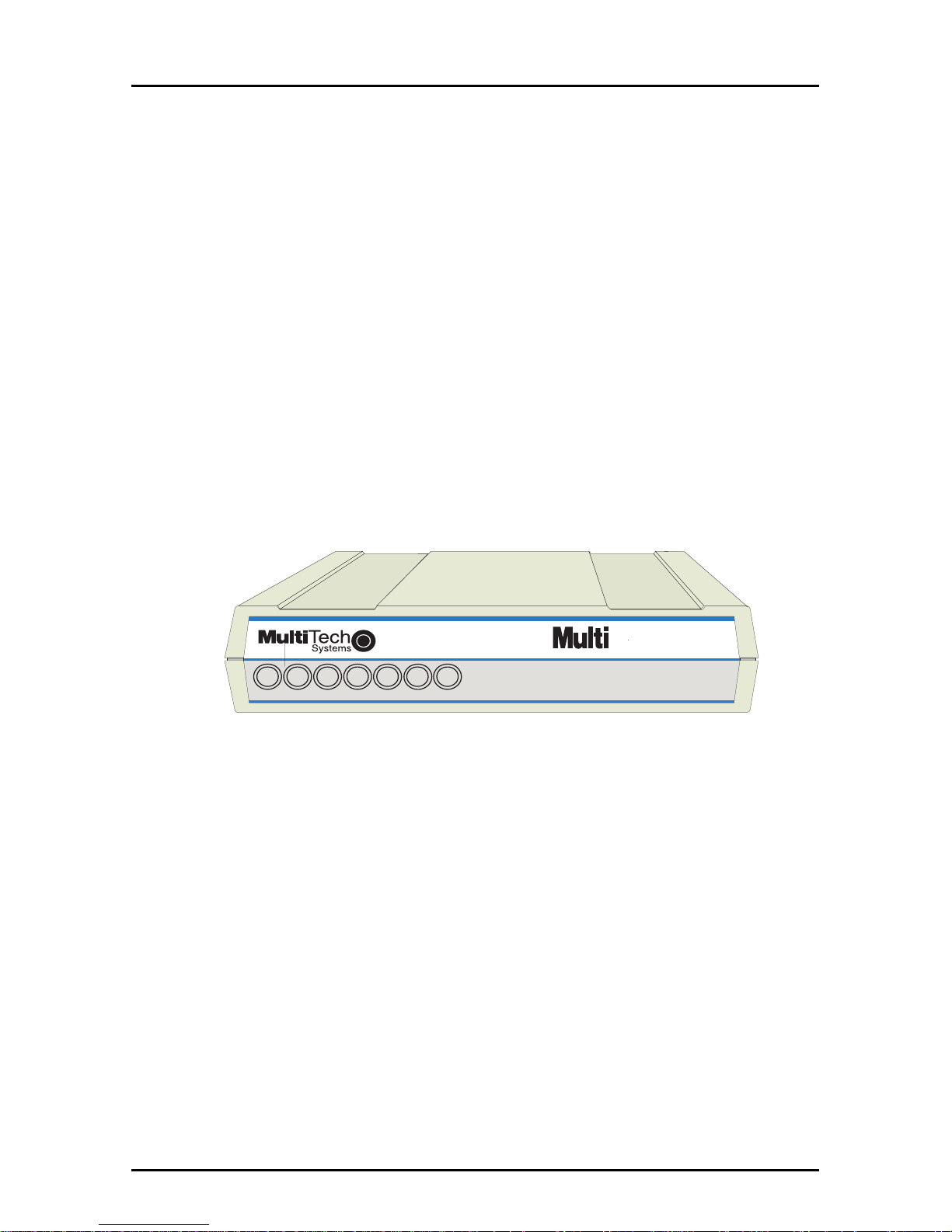
Welcome to Multi-Tech's new MultiDSU64K a stand-alone integrated
Data Service Unit (DSU), model number MT64DSU, for accessing 4-
wire switched or dedicated digital links (Figure 1-1). The
MultiDSU64K is a compact easy to operate unit with features
allowing flexibility in meeting your transmission requirements. The
unit operates with 56 Kbps DDS (Digital Data Services) or switched
4-wire networks or compatible digital data services, and 64 Kbps
dedicated 4-wire services.
The unit contains V.35 and EIA RS-232C connectors on the back
panel to connect a computer or Data Terminal Equipment (DTE) and
a RJ-48 Line jack to connect to your DDS or compatible digital data
service. The MultiDSU64K supports AT dialing for asynchronous
operation and DTR dialing or V.25bis dialing for synchronous
operation.
CTSCD RD
SD
Send RCV Carrier Clear Request On LineTest
RTS
OL
TM
Multi-Rate DSU-CSU
DSU64K
®
Figure 1-1. MultiDSU64K
Page 7

7
Chapter 1 - Introduction and Description
About This Manual
This manual describes the MultiDSU64K and explains how to install
and cable the unit. The information contained in each chapter is as
follows:
Chapter 1 - Introduction and Description
This chapter provides an overview of DSU/CSU basics, information
on power, front panel indicators, back panel connectors, and a list of
the relevant technical specifications.
Chapter 2 - Installation and Cabling
Chapter 2 provides information on connecting the MultiDSU64K to a
computer or DTE device and a DDS network. The chapter provides
a detailed description of each of the MultiDSU64K DIP-Switch
options with all default settings.
Chapter 3 - Testing Your MultiDSU64K
Chapter 3 dicussess the MultiDSU64K's built-in test features.
Chapter 4 - Service, Warranty, Technical Support & BBS
Chapter 4 provides instructions for getting MultiDSU64Ks serviced
at the factory and information on product warranty; information
about Multi-Tech's user Bulletin Board Service (
BBS
), receiving
technical support via the CompuServe/Internet forums and
information on Multi-Tech's Fax-Back Service.
Page 8
8
MT64DSU Owner's Manual
DSU Basic Functions
A DSU (Data Service Unit) and a CSU (Channel Service Unit) are
typically connected to provide the interface between DTE (Data
Terminal Equipment) and the DDS (Digital Data Service) or other
four-wire networks. A DSU converts data to a bipolar format for
transmission over the digital line. The CSU terminates the user's
digital circuit, does the line conditioning, provides FCC Rules
compliance, and handles the CO (Central Office) loopback
commands. The MultiDSU64K contains the functions of a Data
Service Unit (DSU) and a Channel Service Unit (CSU) in a single
package.
DSU Functions
The DSU encodes data as pulses on the communications line by
converting the customer data stream to bipolar format for
transmission over the digital network.
CSU Functions
The CSU is used to terminate the digital circuit at the customer site.
It performs line conditioning functions, ensures network compliance
with FCC rules, and responds to test commands (either from the
telco central office or from the CSU).
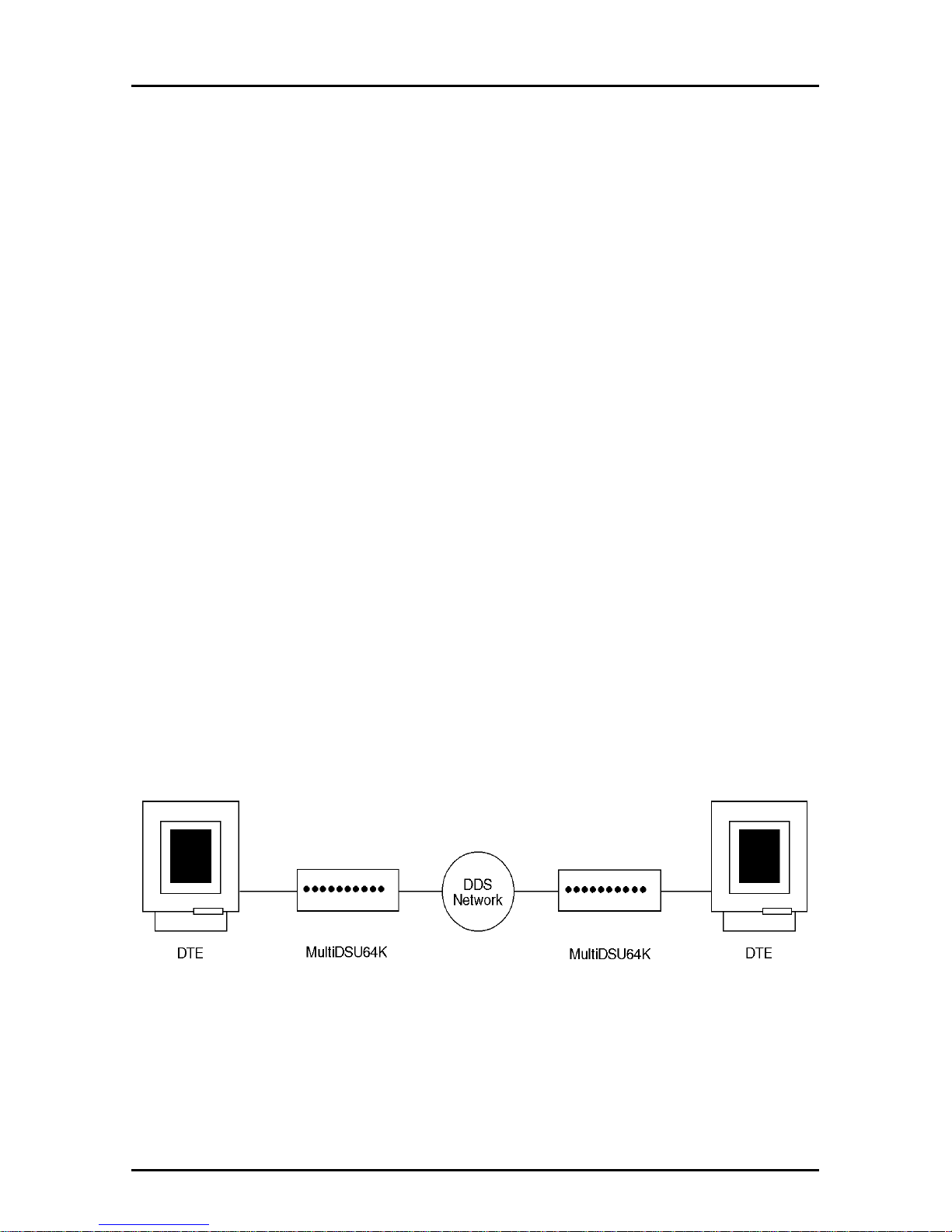
Figure 1-2 shows the MultiDSU64K in a basic DDS network
installation.
Figure 1-2. Basic DSU/CSU Configuration
Page 9
9
Chapter 1 - Introduction and Description
Front Panel Indicators
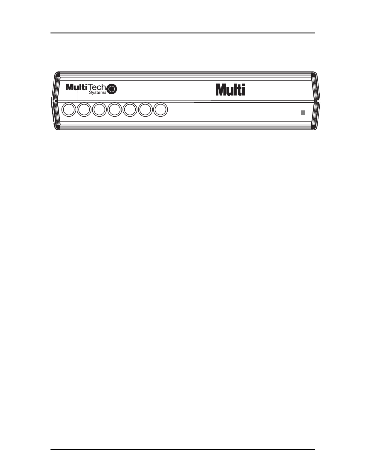
The MultiDSU64K has seven diagnostic LED indicators. They are:
DSU64K
CTSCD RD
SD
Send RCV Carrier Clear Request On LineTest
RTS
OL
TM
Multi-Rate DSU-CSU
®
Figure 1-3. LED Indicators
SD Transmit (Send) Data: This LED blinks when data is
being transmitted, on for a space, off for a mark.
RD Receive Data: This LED blinks when data is being
received, on for a space, off for a mark.
CD Carrier Detect: This LED is lit when a valid signal
from the remote DSU is detected. This indicator is off
if the DSU receives an idle code. If RTS is off at the
remote DSU, then the network sends an idle code to
the local DSU.
CTS Clear To Send: The CTS (Clear to Send) LED lights
when the MultiDSU64K generates a CTS in response
to either an RTS signal received at the DTE connector,
or RTS forced on by the corresponding DIP-Switch.
RTS Request To Send: The RTS LED lights when the RTS
signal is received from the DTE. The DIP-Switch for
RTS Forced On does not affect this indicator. Refer to
Chapter 2 for switch settings.
OL On Line: The OL (On Line) LED lights to indicate the
MultiDSU64K has detected a signal from the network.
TM Test Mode: The TM LED lights when either Local
Loopback (to DTE), Remote Digital Loopback, Digital
Loopback (to line) or Test Pattern DIP-Switches are
enabled. If the Test Pattern DIP-Switch is enabled,
then the TM LED blinks when errors are detected.
When the TM LED is lit, network transmit/receive
operation cannot occur. Refer to the
“Diagnostic”
Tests
section for more information.
Page 10
10
MT64DSU Owner's Manual
Back Panel
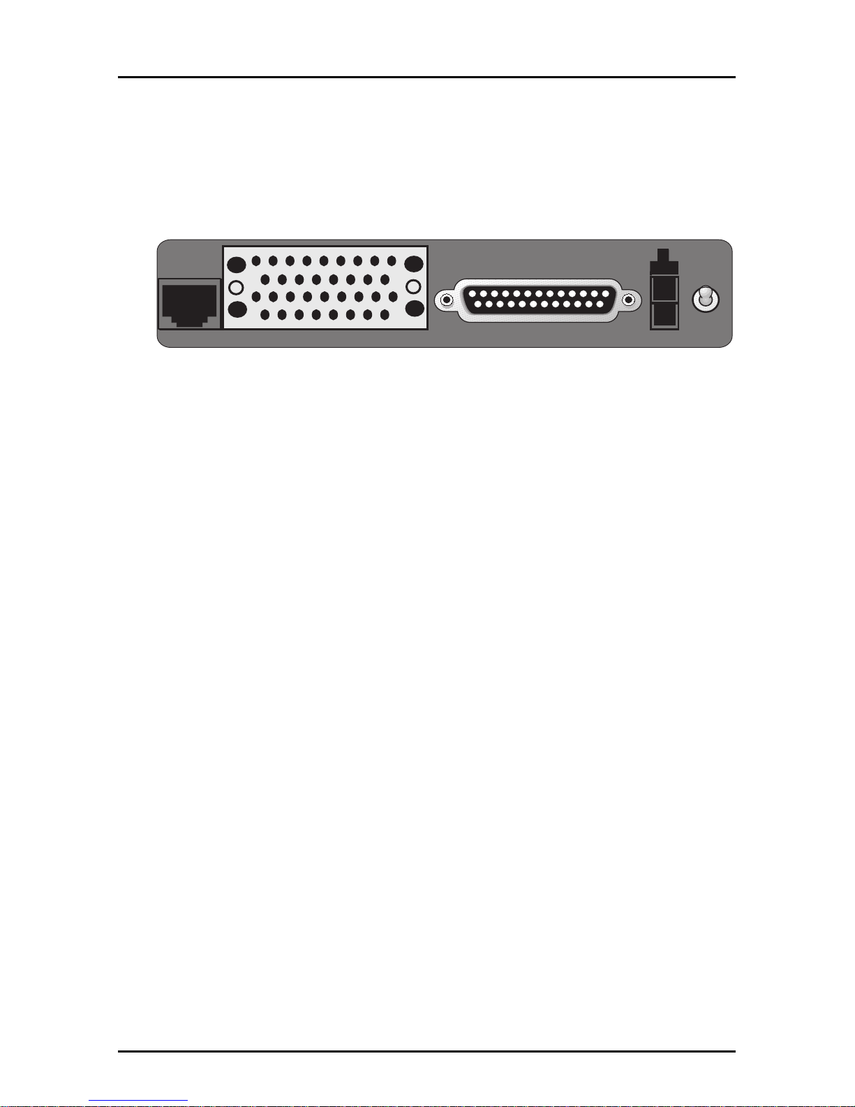
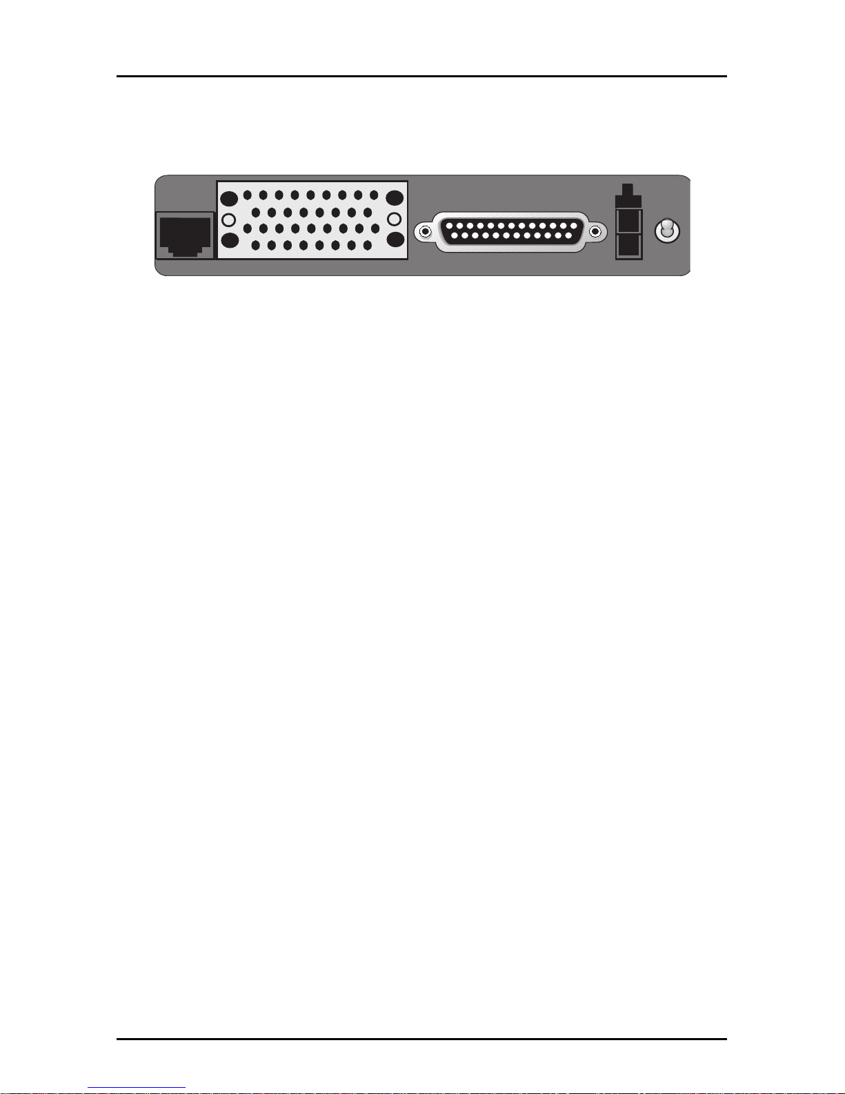
The cable connections for the MultiDSU64K are made at the back
panel. The input data (DCE interface) is through either an RS-232 or
V.35 connection; and, theDDS network connection is through an
RJ48S line jack.
LINE
OFF
ON
POWER
EIA RS232C
Figure 1-4. Back Panel Connectors
RS-232C Connector
The RS-232C connector is used to connect the MultiDSU64K to a
computer or DTE device.
V.35 Connector
The V.35 connector is used to connect the MultiDSU64K to a
computer or DTE device.
RJ48S Jack
The RJ48 line interface jack is used to connect the MultiDSU64K to
a DDS network.
Multi DSU Loopback Cable
The Multi DSU loopback cable is used to test mux internal
composite link DSU or external DSU.
Power Connector
The Power connector is used to connect the external power supply
to the unit.
On/Off Switch
The power switch provides DC power to the unit when placed in the
ON position and terminates power when placed in the OFF position.
Page 11

11
Chapter 1 - Introduction and Description
Features
Your Multi-Tech DSU/CSU provides the following features:
• supports direct connection to the DATAPHONE Digital Data
Service (DDS) or compatible network;
• selectable sync speeds of 9600, 19200, 56000 for 4-wire lines
and 64000 bps for 4-wire dedicated lines;
• selectable async speeds of 9600, 19200, 38400 and 57600 bps;
• Standard RS-232C, V.35 and DDS interfaces provided;
• Automatic rate adaption from DCE data rate to 56 Kbps or 64
Kbps line rate in both sync and async modes; and
• elastic store (for analog off-net extensions).
• multiple selectable clocking
* External clocking
* Internal clocking
* DDS (slave) clocking
• RTS signal forced on selection
• DSR signal forced on selection
• multiple MultiDSU64K-activated diagnostic tests:
* Local loopback test
* Digital loopback test
* Test pattern generator/detector
• multiple Telco-activated diagnostic tests:
* DSU loopback test
* CSU loopback test
• Model Number: MT64DSU
• Device Operation: combined DSU and CSU
Page 12

12
MT64DSU Owner's Manual
Technical Specifications
• Interfaces
RS-232C DB25S (female)
V.35 34-pos. rectangular (female)
DDS RJ48 8-position keyed jack
• Power Requirements 117V AC, 50-60 Hz, 10 Watts
• Temperature 0 to 50 degrees C
• Humidity 95% (non-condensing)
• Dimensions 1.38" H x 6.15" W x 9" D
(3.5 cm x 15.6 cm x 22.9 cm)
• Weight 2 Lbs. (.9 Kg.) without power
transformer 2.7 Lbs. (1.2 Kg.) with
power transformer
• Certification FCC Part 15 Class A FCC Part 68
UL Listed
• Compatibility AT&T Pubs 62310, 41450 and
• FIC Codes 04DU5-56 56 Kbps
Digital Interface 04DU5-64 64 Kbps
• USOC Jack RJ48S - 4-wire
• Modulation bipolar return to zero
• Transmit Level 1.4V peak (+6dBm) into 135 Ohm
• Output Impedance 135 ohms
• Receive Levels +6 to -45 dBm at 64000 bps
• Input Impedance 135 ohms
• RTS Delay: .8mSec
Page 13

MultiDSU64K
Chapter 2 - Installation and Cabling
Page 14
14
MT64DSU Owner's Manual
Introduction
This chapter provides information for configuring and cabling the
MultiDSU64K. It is assumed that the reader is familiar with the
function and operation of data communications equipment and is
technically qualified to provide installation service.
Unpacking
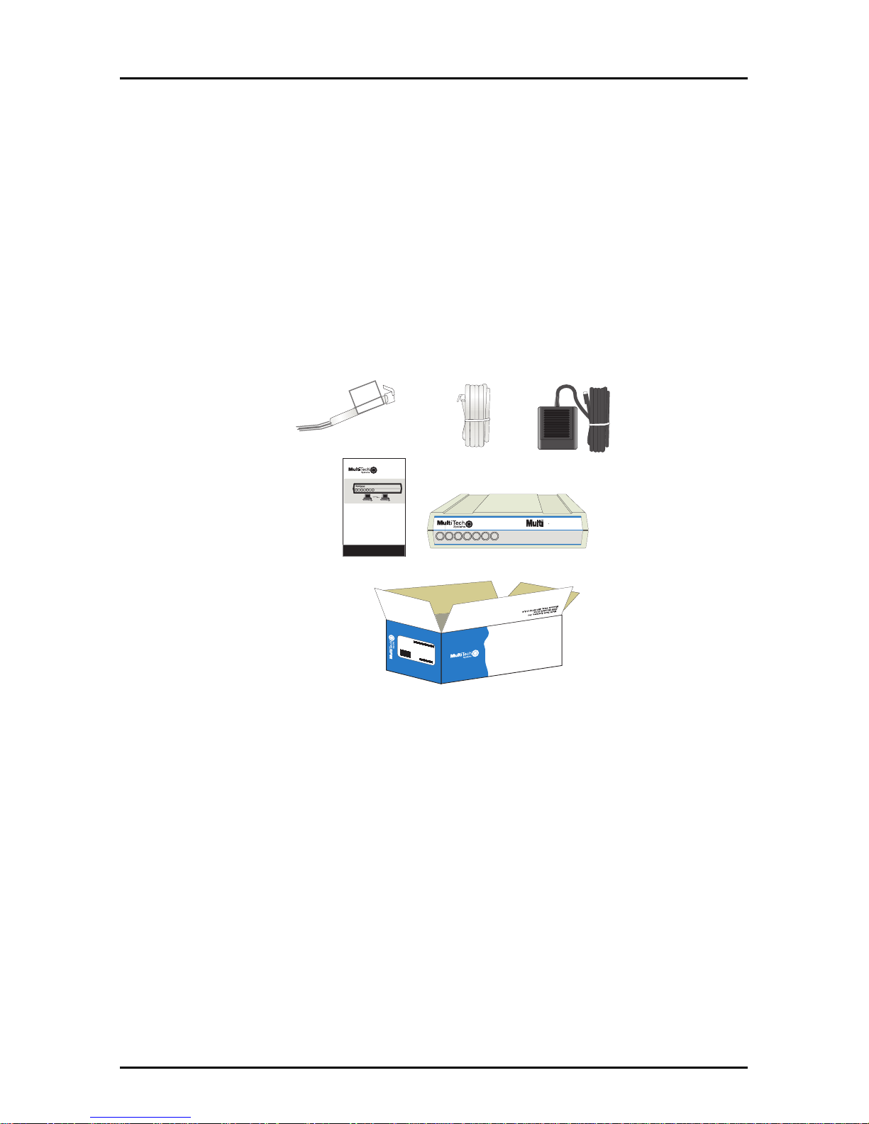
The shipping box contains the MultiDSU64K, an RJ48S line cord, a
DSU Loopback cable, an AC Power Transformer and an Owner ’s
Manual.
MADE IN U.S.A
MADE IN U.S.A
CTSCD RD
SD
Send RCV Carrier Clear Request On LineTest
RTS
OL
TM
Multi-Rate DSU-CSU
DSU64K
®
MultiDSU64K
Multi-Rate DSU/CSU
Model #MT64DSU
Owners Manual
CTSCD RD
SD
Send RCV Carrier Clear Request On LineTest
RTS
OL
TM
Multi-Rate DSU-CSU
64K
®
Figure 2-1. Unpacking
Safety Warnings
1. Never install telephone wiring during a lightning storm.
2. Never install telephone jacks in wet locations unless the jack is
specifically designed for wet locations.
3. Never touch uninsulated telephone wires or terminals unless
the telephone line is disconnected at the network interface.
4. Use caution when installing or modifying telephone lines.
5. Avoid using a telephone (other than a cordless type) during an
electrical storm. There may be a remote risk of electrical shock.
6. Do not use the telephone to report a gas leak near the leak.
Page 15
15
Chapter 2 - Installation and Connection
Cabling Procedure
Installation of the MultiDSU64K includes making the proper cable
connections and turning power on.
LINE
OFF
ON
POWER
EIA RS232C
Figure 2-1. MultiDSU64K Back Panel
Perform the following procedure to install your MultiDSU64K.
1. Verify that the Dip-Switches on the MultiDSU64K are set for
your particular configuration.
2. Connect the appropriate MultiDSU64K back panel DTE
interface connector, depending on the DTE:
• Connect the RS-232C connector to the 25-pin DB25S
receptacle. Use the two screws to secure the connection. Or,
• connect the 34-position rectangular V.35 connector to
the V.35 receptacle.
3. Connect the “LINE” Jack of the MultiDSU64K to the DDS
receptacle using the line cord provided.
Note: any cables connected to the computer must be shielded
to reduce interference.
4. Connect the other end of the interface cable to the DTE’s port
connector.
5. Plug the Power Cord into the POWER jack on the back panel.
6. Plug the power transformer into an appropriate electrical outlet.
Note: Use only the power supply supplied with the
MultiDSU64K. Use of any other power supply will void the
warranty and could damage this device.
7. Turn the POWER switch On. The MultiDSU64K will now operate
with the configuration DIP-Switches set to the most typical
application.
Page 16
16
MT64DSU Owner's Manual
DIP Switch Settings
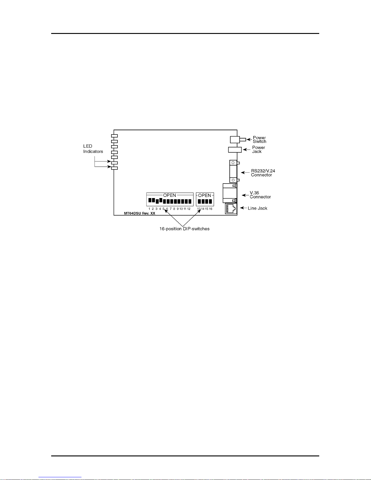
The MultiDSU64K printed circuit board contains one 12-position
DIP-Switch block and one 4-position DIP-Switch block as shown in
Figure 2-2. They are located on the side of the circuit board, and are
accessible through the side of the chassis. Each individual switch is
numbered, and can be in either an up (OPEN) or down (CLOSED)
position.
Figure 2-2. MultiDSU64K PC Circuit Board
The MultiDSU64K is shipped from the factory with the configuration
DIP-Switches set to the most common settings. The factory default
settings are:
• 56 Kbps Data Rate Enabled
• DDS Clocking
• RTS Forced On
• Synchronous Mode On
• Test Pattern Disabled
• Loopback Tests Disabled
• Elastic Store Disabled
• 4-Wire and Dedicated Line Operation Enabled
Page 17

17
Chapter 2 - Installation and Connection
Switches #1 and #2
Speed Switches
(Synchronous Mode)
DIP-Switches #1 and #2 are used to set the synchronous data rate.
Switches #1 and #2 are used in combination, to select the desired
speed in your application. Note that first the asynchronous/
synchronous option must be chosen via DIP-Switch #5.
9600 bps Operation = Switch #1 DN and Switch #2 DN
9200 bps Operation = Switch #1 UP and Switch #2 DN
56000 bps Operation = Switch #1 DN and Switch #2 UP
64000 bps Operation = Switch #1 UP and Switch #2 UP
(Factory Default Setting = Switch #1 DN and Switch #2 UP)
Switches #1 and #2
Speed Switches
(Asynchronous Mode)
DIP-Switches #1 and #2 are used to set the asynchronous data rate.
Switches #1 and #2 are used in combination, to select the desired
speed applications. Note that first the asynchronous/synchronous
option must be chosen via DIP-Switch #5.
9600 bps Operation = Switch #1 DN and Switch #2 DN
19200 bps Operation = Switch #1 UP and Switch #2 DN
38400 bps Operation = Switch #1 DN and Switch #2 UP
57600 bps Operation = Switch #1 UP and Switch #2 UP
(No Factory Default Setting = User Selectable)
Switches #3 and #4
Internal/External/DDS Clocking
(Asynchronous/Synchronous Mode)
DIP-Switches #3 and #4 are used in combination to select clocking
(timing for synchronization) from one of three sources--Internal,
External or DDS Clocking.
Internal clocking
enables the MultiDSU64K to accept timing from its
internal timing oscillator.
External clocking
allows the MultiDSU64K to derive timing from any
external device that can supply timing to the External Transmit Clock
line on the MultiDSU64K’s interface connector. This external clock
must be within 0.008% of the nominal data rate.
Page 18

18
MT64DSU Owner's Manual
DDS clocking
(default) allows the MultiDSU64K to accept timing
signals from the DDS network’s receive bipolar signal. Use this
selection whenever the MultiDSU64K is connected to the DDS
network lines.
Internal Clocking = Switch #3 UP and Switch #4 UP
External Clocking = Switch #3 UP and Switch #4 DN
DDS Clocking = Switch #3 DN and Switch #4 DN
(Factory Default Setting = Switch #3 DN and Switch #4 DN)
Switch #5
Asynchronous/Synchronous Operation
(Asynchronous/Synchronous Mode)
The MultiDSU64K can operate in either Asynchronous or
Synchronous mode. In Synchronous mode, start and stop bits are
eliminated; internal clock circuits for receive and transmit timing on
the RS-232C or V.35 interface are activated.
Asynchronous Operation = Switch #5 UP
Synchronous Operation = Switch #5 DOWN
(Factory Default Setting = DOWN)
Switch #6
Request To Send Forced - "RTS"
(Asynchronous/Synchronous Mode)
With this option enabled, the MultiDSU64K provides a continuous
CTS signal, and disregards the state of the RTS signal at the DTE
interface. This provides a continuous outbound indication to the
network and remote device that there is a “
Carrier on
”. For many
networks (e.g., point-to-point), it is best to maintain a “
Carrier on
”
status on the communications channel to help minimize line
turnaround delays. This option is usually enabled for central site
DSU installations with multipoint lines (i.e., when continuous
outbound “
Carrier on
” is desired). This option must be disabled on
the remote station of a multipoint installation. When this option is
disabled, the MultiDSU64K receives and uses the RTS signal from
the DTE.
RTS functions Normally = Switch #6 UP
RTS forced On = Switch #6 DOWN
(Factory Default Setting = DOWN)
Page 19

19
Chapter 2 - Installation and Connection
Switch #7
Data Set Ready "DSR"
(Asynchronous/Synchronous Mode)
When this option is enabled, the MultiDSU64K forces the DSR
signal on continuously. The continuous DSR signal is used to
eliminate momentary link interruptions that may be interpreted by
the DTE as a communications channel failure.
DSR controlled by DSU = Switch #7 UP
DSR Forced On = Switch #7 DOWN
(Factory Default Setting = DOWN)
Switch #8
Local Loopback Test (to DTE)
Refer to Diagnostics Tests section in Chapter 4.
Switch #9
Digital Loopback Test (to the Line)
Refer to Diagnostics Tests section in Chapter 4.
Switch #10
Remote Digital Loopback Test
Refer to Diagnostics Tests section in Chapter 4.
Switch #11
Test Pattern
Refer to Diagnostics Tests section in Chapter 4.
Switch #12
Elastic Store
(Asynchronous/Synchronous Mode)
This function allows the MultiDSU64K to compensate for small
timing phase
“drifts”
that occur in applications using analog modems
for off-net (non-DDS) extensions. An analog off-net extension
application is described in Appendix A. This option should be
enabled on all MultiDSU64Ks that are connected to analog
modems.
Page 20

20
MT64DSU Owner's Manual
Elastic Store Enabled = Switch #12 UP
Elastic Store Disabled = Switch #12 DOWN
(Factory Default Setting = DOWN)
Switch #13
This switch must be in the DOWN position.
Switch #14
Dedicated/Switched Line Operation
(Asynchronous/Synchronous Mode)
The MultiDSU64K works over either Dedicated or Switched lines.
Note you must have this switch positioned in Switched Line mode
(UP) in order to issue AT Commands.
Switched Line = Switch #14 UP
Dedicated Line = Switch #14 DOWN
(Factory Default Setting = DOWN)
Switch #15
DTR Forcing
(Asynchronous/Synchronous)
It is advisable to force DTR in order for the terminal to communicate
properly with the DSU in Command mode.
DTR Controlled by DTE = Switch #15 UP
DTR forced On = Switch #15 DOWN
(Factory Default Setting = DN)
Switch #16
This switch is not used (reserved for future use).
Page 21

MultiDSU64K
Chapter 3 - Testing
Page 22
22
MT64DSU Owner's Manual
Diagnostic Tests
The MultiDSU64K is set to a default of Normal (non-diagnostic)
mode at the factory.
When a failure occurs in the digital facility (DDS circuit), the network
detects the failure. Your equipment can detect failure by the
absence or distortion of the digital signal. If the remote equipment is
not transmitting properly, contact your telephone company. If the
telco is required to perform remote tests, the channel will be
temporarily interrupted and loss of data may occur. The following
sections describe the diagnostic tests available for the
MultiDSU64K.
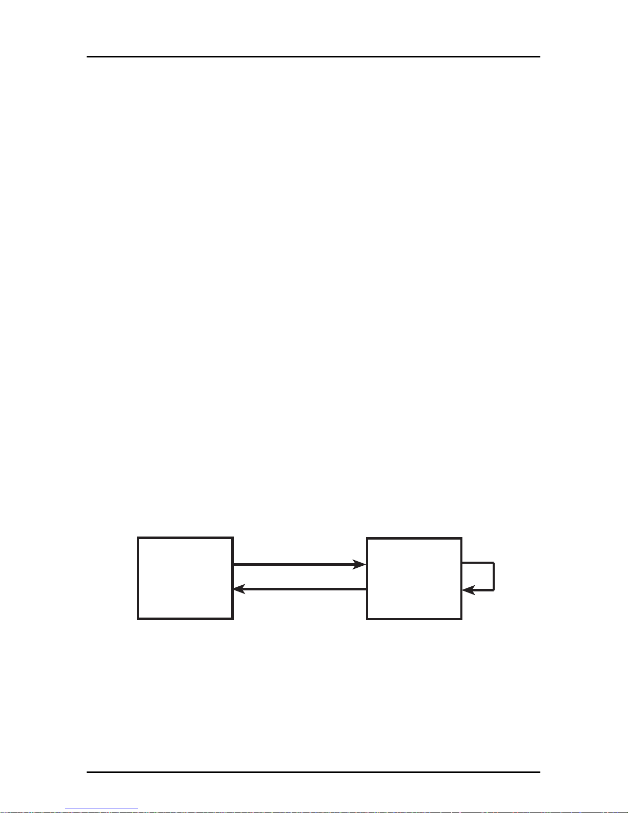
DSU Loopback Test
This test lets you verify proper DSU operation by matching a
transmitted signal to the
“looped-back”
receive signal. Refer to
Appendix B for cable description. Note: The DSU must be in 4-wire
dedicated line mode to perform this test.
1. Obtain a DSU Loopback cable (#45640100) from Multi-Tech, or
assemble one. Refer to Appendix B for instructions on building
the Loopback cable.
2. Plug the Loopback cable into the back panel LINE jack.
3. If you send data from your DTE, it should be “looped back” to
your DTE. If you have access to a Bit Error Rate Tester, this can
be used in place of the DTE.
Figure 3-1. DSU Loopback Test with Loopback Cable
Loopback
Cable
DSU
being tested
DTE
Page 23
23
Chapter 3 - Testing
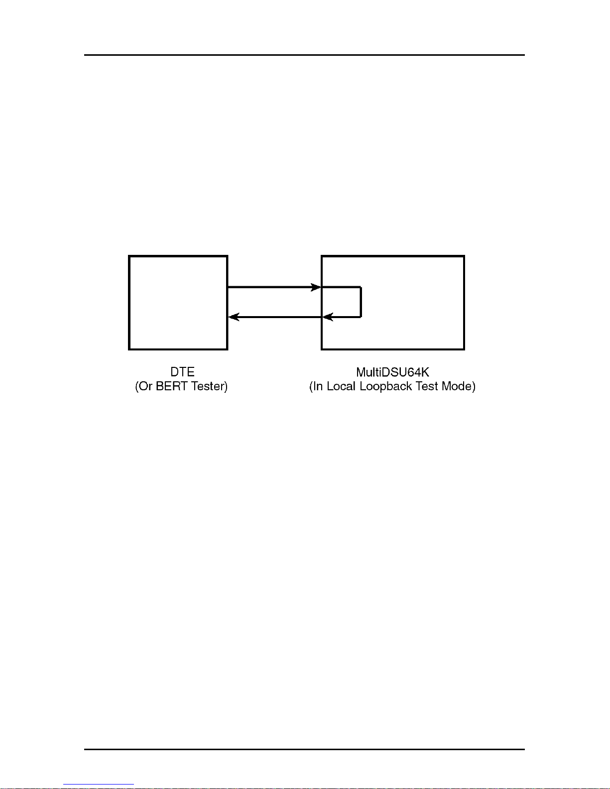
Local Loopback Test
This test allows you to test the local DTE and the local
MultiDSU64K. Use the following steps to perform the Local
Loopback Test.
1. Set DIP-Switch #8 to the UP position.
2. The front panel Test (TM) LED lights, and if you send data from
your DTE, it should be “looped back” to your DTE. If you have
access to a Bit Error Rate Tester, this can be used in place of
the DTE.
Figure 3-2. Local Loopback Test
Page 24
24
MT64DSU Owner's Manual
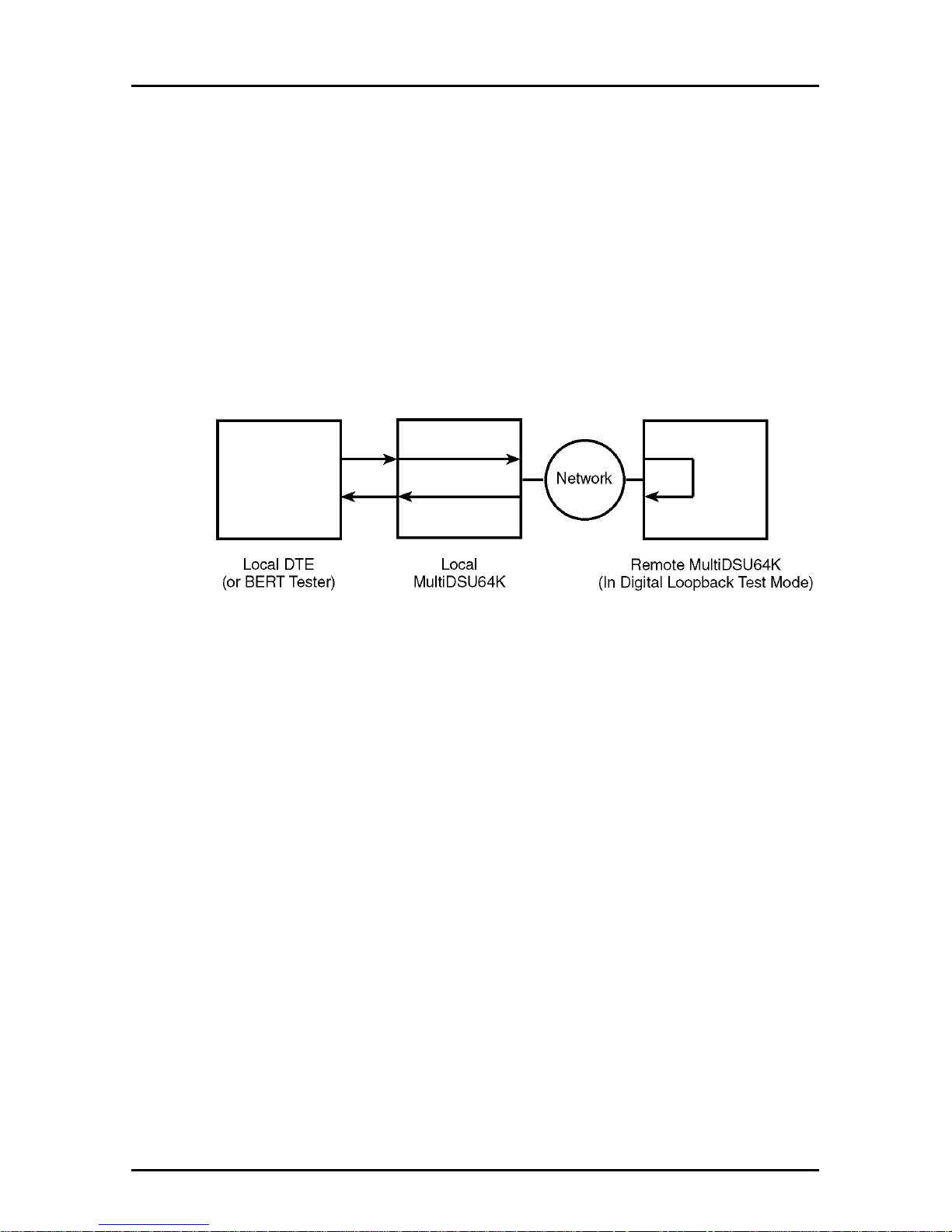
Digital Loopback Test
This test allows you to test the local DTE, the local MultiDSU64K,
the communications link, and the remote MultiDSU64K. Use the
following steps to perform the Digital Loopback Test.
1. Set DIP-Switch #9 on the remote MultiDSU64K to the UP
position.
2. The front panel Test (TM) LED lights, and if you send data from
the local DTE, it should be looped back to the local DTE. If you
have access to a Bit Error Rate Tester, this can be used in place
of the local DTE.
Figure 3-3. Digital Loopback Test
Page 25
25
Chapter 3 - Testing
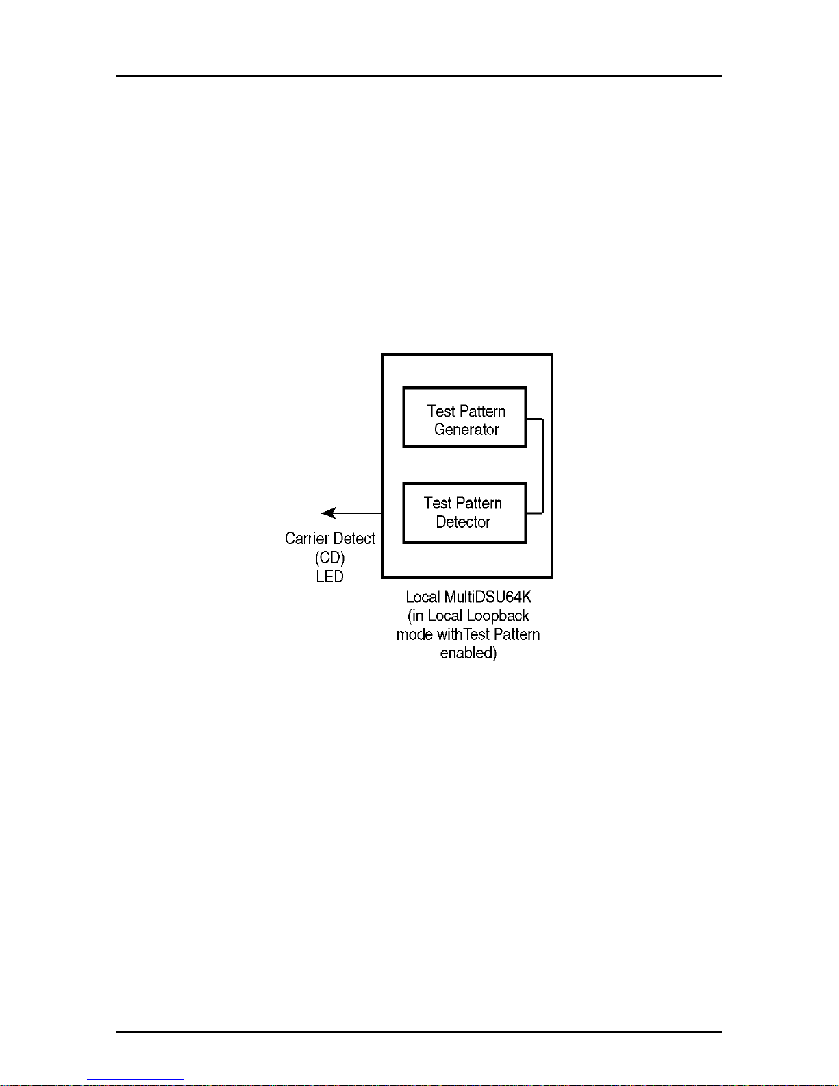
Local Loopback Test With Test Pattern
This test allows you to test the local MultiDSU64K.
Perform the following steps to enable this test:
1. Set DIP-Switch #8 to the UP position.
2. Set DIP-Switch #11 to the UP position.
3. The front panel (TM) LED lights, and if errors are detected, the
Carrier Detect LED blinks.
Figure 3-4. Local Loopback Test with Test Pattern
Page 26
26
MT64DSU Owner's Manual
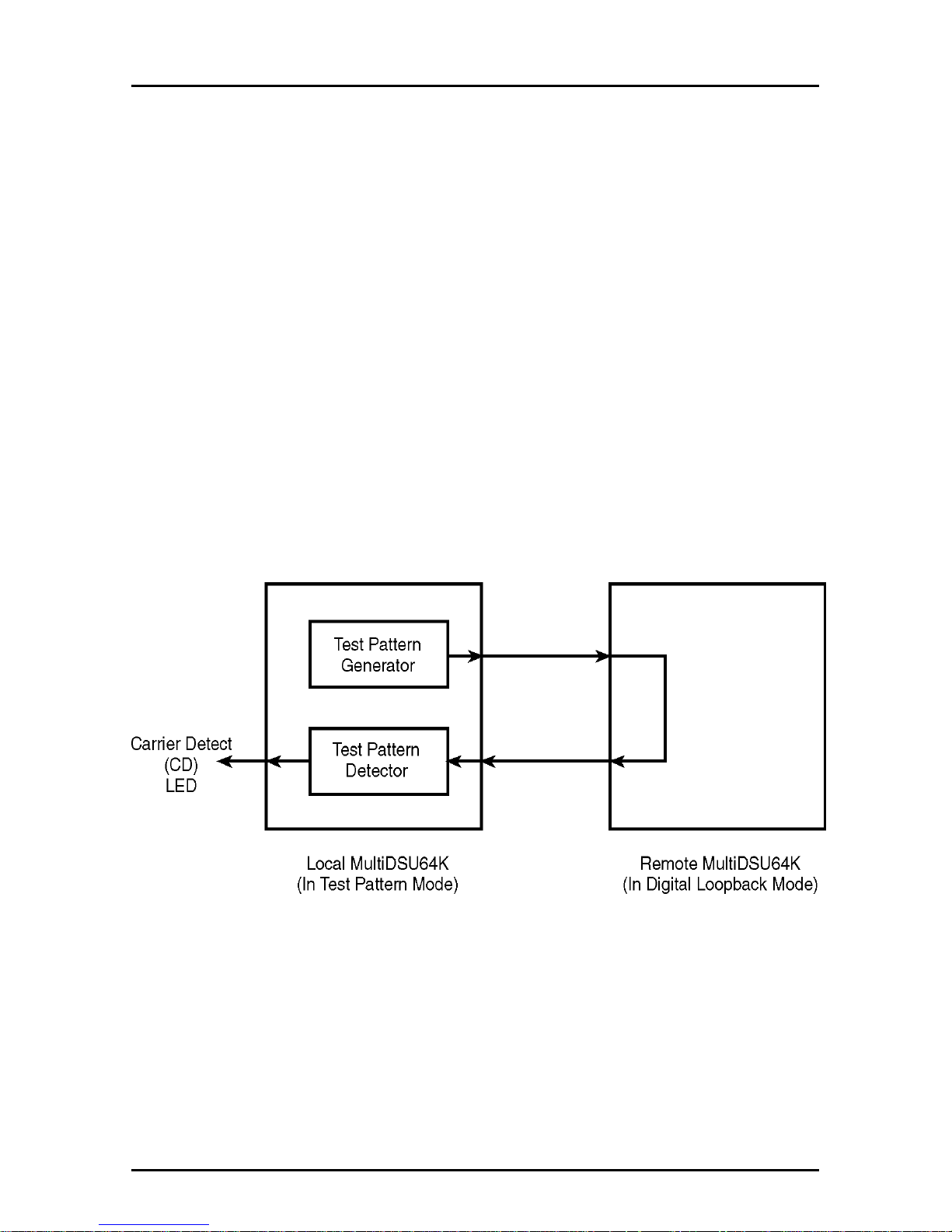
Digital Loopback Test With Test Pattern Test
This test allows you to test the local MultiDSU64K, the
communications link, and the remote MultiDSU64K. Use the
following steps to perform the Digital Loopback Test with the Pattern
Test.
With this test enabled, the MultiDSU64K sends and detects a
predefined 511-bit pseudo-random test pattern. When an error is
detected by the MultiDSU64K, the CD (Carrier Detect) LED flashes.
1. Set DIP-Switch #9 on the remote MultiDSU64K to the UP
position.
2. Set DIP-Switch #10 on the local MultiDSU64K to the DOWN
position.
3. The test pattern is generated and either detected as a good test
pattern (test patterns match) or as a failed test (test pattern
received does not match the pattern sent).
Figure 3-5. Digital Loopback with Test Pattern Test
Page 27
27
Chapter 3 - Testing
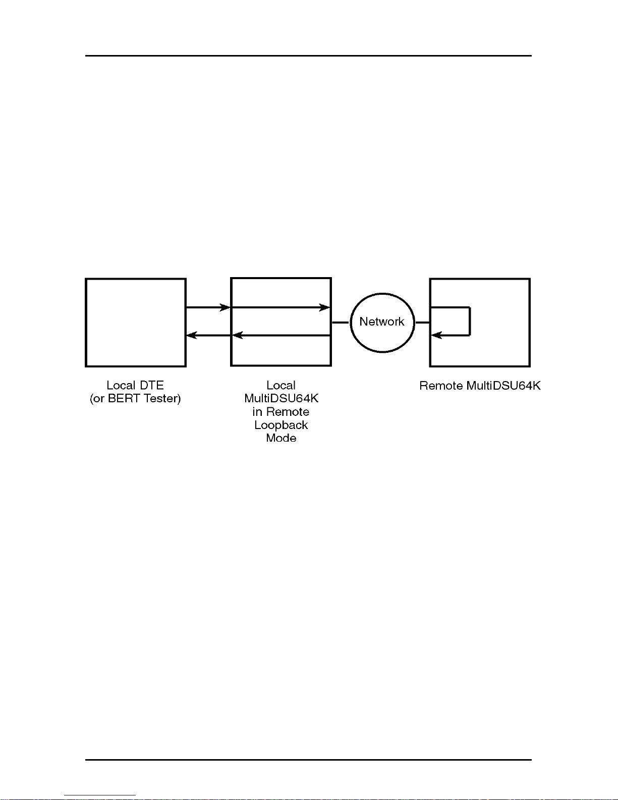
Remote Loopback Test
This test allows you to test the local DTE, the local MultiDSU64K,
the communications link, and the remote MultiDSU64K. Use the
following steps to perform the Remote Loopback Test.
1. Set DIP-Switch #10 on the local MultiDSU64K to the UP
position.
2. The front panel Test (TM) LED lights, and if you send data from
the local DTE, it should be looped back to the local DTE. If you
have access to a Bit Error Rate Tester, this can be used in place
of the local DTE.
Figure 3-6. Remote Loopback Test
Page 28
28
MT64DSU Owner's Manual
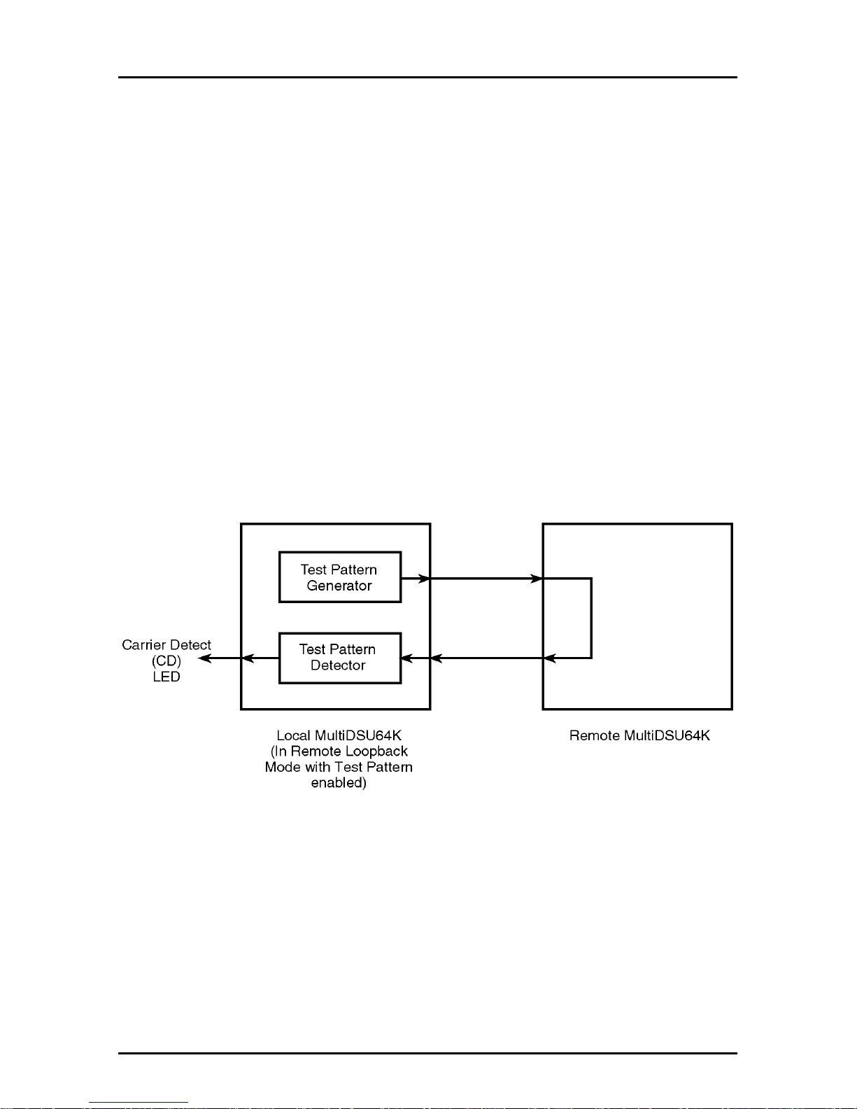
Remote Loopback Test With Test Pattern Test
This test allows you to test the local MultiDSU64K, the
communications link, and the remote MultiDSU64K. Use the
following steps to perform the Remote Loopback Test with the
Pattern Test.
With this test enabled, the MultiDSU64K sends and detects a predefined 511-bit pseudo-random test pattern. When an error is
detected by the MultiDSU64K, the CD (Carrier Detect) LED flashes.
1. Set DIP-Switch #10 on the local MultiDSU64K to the UP
position.
2. Set DIP-Switch #11 on the local MultiDSU64K to the UP
position.
3. The test pattern is generated and either detected as a good test
pattern (test patterns match) or as a failed test (test pattern
received does not match the pattern sent).
Figure 3-7. Remote Loopback with Test Pattern Test
Page 29
29
Chapter 3 - Testing
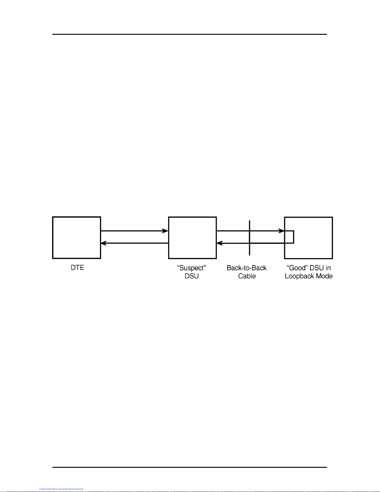
DSU Back-to-Back Test
This test lets you connect two DSUs with a back-to-back cable to
verify proper DSU operation. Using a DSU that is known to be
operational, you can test a second DSU that is suspect.
1. Obtain a DSU Back-to-Back cable (#45050000) from Multi-Tech,
or assemble one. Refer to Appendix B for instructions on
building the Back-to-Back cable.
2. Plug the cable into each DSU’s LINE jack.
3. On the
“good”
DSU, set DIP switch #9 to the UP position.
4. Set one DSU to internal clocking and the other DSU to DDS
clocking.
5. If you send data from your DTE, it should be “looped back” to
your DTE. If you have access to a Bit Error Rate Tester, this can
be used in place of the DTE.
Figure 3-8. Back-to-Back Testing
Page 30

30
MT64DSU Owner's Manual
Page 31

MultiDSU64K
Chapter 4 - Warranty, Service and
Tech Support
Page 32

32
MT64DSU Owner's Manual
Introduction
This chapter starts out with statements about your MultiDSU64K's
two-year warranty. The next section, Tech Support, should be read
carefully if you have questions or problems with your MultiDSU64K.
It includes the technical support telephone numbers, space for
recording your MultiDSU64K information, and an explanation of how
to send in your MultiDSU64K should you require service. The next
three sections explain how to use our Bulletin Board Service (
BBS
)
and receive support through CompuServe and the Internet forums.
The final section explains how to obtain a catalog of available
documents and then order technical literature using our 24-hour
Fax-Back Service.
Limited Warranty
Multi-Tech Systems, Inc. (
“MTS”
) warrants that its products will be
free from defects in material or workmanship for a period of two
years from the date of purchase, or if proof of purchase is not
provided, two years from date of shipment. MTS MAKES NO
OTHER WARRANTY, EXPRESSED OR IMPLIED, AND ALL
IMPLIED WARRANTIES OF MERCHANTABILITY AND FITNESS
FOR A PARTICULAR PURPOSE ARE HEREBY DISCLAIMED. This
warranty does not apply to any products which have been damaged
by lightning storms, water, or power surges or which have been
neglected, altered, abused, used for a purpose other than the one
for which they were manufactured, repaired by the customer or any
party without MTS’s written authorization, or used in any manner
inconsistent with MTS’s instructions.
MTS WILL NOT BE LIABLE FOR CONSEQUENTIAL DAMAGES
AND UNDER NO CIRCUMSTANCES WILL ITS LIABILITY EXCEED
THE PURCHASE PRICE FOR DEFECTIVE PRODUCTS.
On-line Warranty Registration
If you would like to register your RouteFinder electronically, you can
do so at the following address:
http://www.multitech.com/support/register.htm
Page 33

33
Chapter 4 - Warranty, Services, and Tech Support
Tech Support
Multi-Tech has an excellent staff of technical support personnel
available to help you get the most out of your Multi-Tech product. If
you have any questions about the operation of this unit, call 1-800972-2439. Please fill out the MultiDSU64K information (below), and
have it available when you call. If your MultiDSU64K requires
service, the tech support specialist will guide you on how to send in
your MultiDSU64K.
Recording MultiDSU64K Information
Please fill in the following information on your Multi-Tech
MultiDSU64K. This will help tech support in answering your
questions. (The same information is requested on the Warranty
Registration Card.)
Model No.:
_______________________________
Serial No.:_______________________________
Firmware Version:_________________________
The MultiDSU64K model and serial numbers are silkscreened on
the bottom of your modem. Type ATI for MultiDSU64K firmware
version.
Please note the status of your MultiDSU64K before calling tech
support. This status can include LED indicators, screen messages,
diagnostic test results, problems with a specific application, etc. Use
the space below to note MultiDSU64K status:
~Notes~
Page 34

34
MT64DSU Owner's Manual
Service
If your tech support specialist decides that service is required, your
MultiDSU64K may be sent (freight prepaid) to our factory. Return
shipping charges will be paid by Multi-Tech Systems).
Include the following with your MultiDSU64K:
• a description of the problem.
• return billing and return shipping addresses.
• contact name and phone number.
• check or purchase order number for payment if the MultiDSU64K
is out of warranty. (Check with your technical support specialist for
standard repair charges.)
• if possible, note the name of the technical support specialist with
whom you spoke.
If you need to inquire about the status of the returned product, be
prepared to provide the serial number of the product sent.
Send MultiDSU64Ks to this address:
MULTI-TECH SYSTEMS, INC.
2205 WOODALE DRIVE
MOUNDS VIEW, MINNESOTA 55112
ATTN: SERVICE OR REPAIRS
The Multi-Tech BBS
For customers who do not have Internet access, Multi-Tech Systems
maintains a bulletin board system (BBS) that mirrors its FTP site.
Information available from the BBS includes new product
information, product upgrade files, and problem-solving tips. The
phone number for the Multi-Tech BBS is (800) 392-2432 (USA and
Canada) or (612) 785-3702 (international and local).
The BBS can be accessed by any asynchronous modem operating
at 1200 bps to 56 Kbps at a setting of 8 bits, no parity, and 1 stop bit
(8-N-1).
Page 35

35
Chapter 4 - Warranty, Services, and Tech Support
To log on to the Multi-Tech BBS
1. Set your communications program to 8-N-1.
2. Dial our BBS at (800) 392-2432 (USA and Canada) or
(612) 785-3702 (international and local).
3. At the prompts, type your first name, last name, password;
then press ENTER. If you are a first time caller , the BBS
asks if your name is spelled correctly. If you answer yes, a
questionnaire is displayed. You must complete the
questionnaire to use the BBS on your first call.
4. Press ENTER until the Main Menu is displayed. From the
Main Menu you have access to two areas: the Files Menu
and News. For help on menu commands, type ?.
To Download a file
If you know the file name
1. From Main Menu, type F to access Files Menu, then D.
2. Enter name of the file you wish to download from the BBS.
3. If a password is required, enter the password.
4. Answer Y or N to the automatic logof f question.
5. Select a file transfer protocol by typing the indicated letter,
such as Z for Zmodem (the recommended protocol).
6. If you select Zmodem, the transfer will begin automatically.
If you select another protocol, you may have to initiate the
transfer yourself. (In most datacomm programs, the PAGE
DOWN key initiates the download.)
7. When the download is complete, press ENTER to return to
the File Menu.
8. To exit the BBS, type G and press ENTER.
If you don’t know the file name
1. From the Main Menu, type F to access the Files Menu. For
a list of file areas, type L, press ENTER, then type L and
press ENTER again. (If you do not type the second L, you
will list all of the files on the BBS.)
Page 36

36
MT64DSU Owner's Manual
2. Mark each file area you would like to examine by typing its
list number and pressing ENTER.
3. Enter L to list all the files in the selected file areas. Enter C
to go forward in the file list and P to go back.
4. To mark one or more files for download, type M, press
ENTER, type the list numbers of the files, and press
ENTER again.
5. Enter D. You will see a list of the files you have marked.
Enter E if you would like to edit the list; otherwise enter D
again to start the download process.
6. Select a file transfer protocol by typing the indicated letter,
such as Z for Zmodem (the recommended protocol).
7. If you select Zmodem, the file will transfer automatically. If
you select another protocol, you may have to initiate the
transfer yourself. (In most data communications programs,
the PAGE DOWN key initiates the download.)
8. When completed, press ENTER to return to the File Menu.
9. To exit the BBS, type G and press ENTER.
About CompuServe
In addition to the BBS, Multi-Tech provides support through
CompuServe's Modem Vendor Forum (
GOMODEMVEN
). Refer to
your CompuServe documentation for special operating procedures.
About the Internet
AIf you prefer to receive technical support via the Internet, you can
contact Tech Support via e-mail at the following address:
http:\\www.multitech.com\_forms\email_tech_support.htm
Multi-Tech’s presence includes a Web site at:
http://www.multitech.com
and an ftp site at:
ftp://ftp.multitech.com
Page 37

37
Chapter 4 - Warranty, Services, and Tech Support
About the Multi-Tech Fax-Back Service
Multi-Tech’s fax-back system provides 24-hour access to sales,
marketing, and technical literature. Dial 612-717-5888, follow the
voice prompts, and request document number 10 for a catalog of
available documents.
For convenience, have your fax number ready: ________________.
From the catalog of available documents, you can order newsletters,
white papers, press releases, etc. from the sales and marketing
index (pages 1-4), or order basic modem operation and
troubleshooting guides from the technical support and engineering
index. Just enter the applicable FB Doc. # from the left column of
the catalog.
Page 38

38
MT64DSU Owner's Manual
Page 39

MultiDSU64K
Appendixes
Page 40

40
MT64DSU Owner's Manual
Appendix A - AT Commands and S-Registers
Introduction
AT commands are the means by which you, and your datacomm
software, are able to communicate with and configure your
MultiDSU64K. They enable you to establish, read, and modify
parameters in addition to dialing.
Certain configuration parameters are stored in S-Registers. These
Registers may be read, may be written to directly or may be
modified by other AT Commands.
V.25bis commands provide an alternate set of commands and
responses for applications in which the DTE is synchronous.
V.25bis commands do not include any configuration commands; you
can, however, execute AT/S-Register commands to configure
V.25bis mode operation.
The following sections describe which AT Commands, S-Registers
and V.25bis commands are active in configuring and operating your
MultiDSU64K.
AT Commands
A wide variety of autodial operations and options can be controlled
when the MultiDSU64K is in Command Mode (Switch 14 UP).
Remember, nearly all commands have an
AT
prefix. These
commands are organized into several functional groups. Options
shown in boldface represent factory defaults.
Configuration Commands
E0 No Command Echo
E1 Enable Command Echo
Q0 Enable Result Codes
Q1 No Result Codes
V0 Terse Result Codes
V1 Verbose Result Codes
Page 41

41
Appendixes
Action Commands
A/ Re-execute previous command (no AT prefix required
with this command).
DS
n
Dial a stored number (
n = 0 thru 9 memory location
).
Ten phone numbers can be stored.
D
xxx
Number of characters allowed in a telephone number
string
.
A telephone number
xxx
may contain a
maximum of 16 characters. Note digital circuits do not
provide the option of either pulse or tone dialing. The
MultiDSU64K, however, will accept either ATDT or
ATDP dialing prefix.
H0 Hang-up (go on-hook)
H1 Go on-line (off-hook)
I ID information
&F Load factory default settings
&Zn =
ddd
Store a telephone number
ddd
in phone
number memory
n (n
has ten locations of memory 0
thru 9).
&Z
?
Display all telephone numbers.
&Zn? Display stored phone number (n = memory location 0
thru 9).
*R Reset the MultiDSU64K
*W Download parameters to remote unit. All S-Registers
S0 through S16; as well as the settings of DIPSwitches 1, 2, 5 thru 7 and 12 can be loaded to the
remote unit with this command (S-Registers are
described in this subsection).
$ Display HELP information on-screen.
Page 42

42
MT64DSU Owner's Manual
S-Registers
Certain configurations are stored in memory registers called,
S-Registers. The S command is used to assign a value to, and to
read the current value of an S-Register. To assign a value to an SRegister, enter the letter S, followed by the S-Register number and
an equals sign (=). To read anS-Register value, enter the letter
S
followed by the S-Register number and a question mark (?), then hit
RETURN (e.g.,
A TS8?<CR>
). You should receive a response of the
assigned value given to that S-Register. Options shown in boldface
represent the factory default settings.
S0 Auto-Answer
S0 = 0 Auto-Answer Disabled
S0 = 1 Auto-Answer Enabled
S0 = 2 Auto-Answer under DTR control
S1 Number of Redials
S1 = 0 through 99 (user selectable)
S2 Sync DTE Dialing
S2 = 0 Sync DTE Dialing Disabled
S2 = 1 Dial on DTR transition from low-to-high
S2 = 2 V.25bis sync dialing enabled
S2 = 3 V.25bis or DTR
S3 Auto-Disconnect
S3 = 0 Disconnect when DTR drops
S3 = 1 Disconnect after 10 minutes of data inactivity
S3 = 2 Disconnect after 30 minutes of data inactivity
S3 = 3 Disconnect after 60 minutes of data inactivity
S3 = 4 Disconnect when DTR drops or after 0 minutes of
data inactivity
S3 = 5 Disconnect when DTR drops or after 30 minutes
of data inactivity
S3 = 6 Disconnect when DTR drops or after 60 minutes
of data inactivity
S3 = 7 Auto-Disconnect Disabled
Page 43

43
Appendixes
S4 DCE Interface Mode
S4 = 0 DCE Interface is Async
S4 = 1 DCE Interface is Sync
S5 (Not Used)
S6 (Not Used)
S7 Echo Canceler Tone
S7 = 0 Echo Canceler Tone Disabled
S7 = 1 Echo Canceler Tone Enabled
S8 RTS Control
S8 = 0 RTS On
S8 = 1 CTS follows RTS
S9 DSR Control
S9 = 0 DSR On
S9 = 1 DSR off in Test Mode or when Off-line
S10(Not Used)
S11(Not Used)
S12 Async data bits excluding start/stop/parity bits
S12 = 0 8 bits
S12 = 1 7 bits
S13 Async Stop bits
S13 = 0 1 bit
S13 = 1 1.5 bits
S13 = 2 2 bits
S14 Async Parity
S14 = 0 None
S14 = 1 Even
S14 = 2 Odd
Page 44

44
MT64DSU Owner's Manual
S15 Async DTE Dialing
S15 = 0 Disabled
S15 = 1 DTR low-to-high Transition
S15 = 2 AT Command
S15 = 3 DTR or AT Command
S16 V.25bis Auto-Dialing Format
S16 = 0 Bit-oriented
S16 = 1 Byte-oriented
S17(Not Used)
S18(Not Used)
S19 Parameter Lock
Parameter lock prevents download from remote unit
S19 = 0 Off
S19 = 1 On
Page 45

45
Appendixes
Result Codes
When the MultiDSU64K receives an AT command from the terminal
or PC, the MultiDSU64K tries to execute the command, then sends
a status message to the PC or terminal which reports the
"results"
of
the command (hence the name
"result codes"
). The MultiDSU64K
provides you with several responses, or
“Result Codes”
, that provide
visual responses during Command mode operation. These Result
Codes, when activated by an AT command are displayed on your
video monitor.
ATQ0
enables Result Code display; and entering
ATQ1
disables Result Code display.
You can choose to have these Result Codes displayed in either
“verbose”
(full words) or
“terse”
(digits) format. This is controlled by
the
ATV0
(terse) or
ATV1
(verbose) commands. The MultiDSU64K
defaults to verbose format.
MultiDSU64K Result Codes
TERSE VERBOSE
0OK
1 CONNECT
2 RING
3 NO CARRIER
4 ERROR
5 NO ANSWER
6 NO DIALTONE
7 REDIAL
8 DIAL IN PROGRESS
9 DOWNLOAD SUCCESS
10 DOWNLOAD FAILURE
11 REMOTE CONFIGURATION LOCKED
Page 46

46
MT64DSU Owner's Manual
Configuration Options
This section describes the configuration parameters option settings.
Corresponding S-Registers and AT commands are listed for each
option or function.
Synchronous Options
If the MultiDSU64K is configured for synchronous operation (*S4=1),
the following options apply:
DTE Dialing (S2) - Selects the option for dialing synchronously.
The options are V.25bis, DTR, V.25bis or DTR and DISABLED.
When V.25bis is selected, the unit auto-dials in accordance with
V.25bis commands. When DTR is selected, the unit dials a stored
number in the memory location of 0 whenever DTR goes from lowto-high. If the combination option of V.25bis or DTR is selected,
then the unit responds to either V.25bis commands or DTR going
high. The DISABLED option prevents any auto-dialing. The factory
default setting is V.25bis-- S2 = 2.
V.25bis Auto-Dial (S16) - The V.25bis data format may be either bitoriented (HDLC-like) or byte-oriented (character) depending on the
protocol requirements of the DTE. The factory default setting is Bitoriented-- S16 = 0.
Note: that upon power-up the MultiDSU64K responds to default
DIP-Switch settings.
Asynchronous Options
If the MultiDSU64K is configured for asynchronous data (S4=0), the
following options apply:
Data Bits (S12) - Sets the MultiDSU64K data character format for
either 7 or 8 data bits. Data bits do not include start, stop or parity
bits. The factory default setting is for 8 bits--S12 = 0.
Stop Bits (S13) - Sets the MultiDSU64K data character for 1, 1.5 or
2 stop bits. The factory default setting is 1-- S13 = 0.
Parity (S14) - Sets the MultiDSU64K data character format to use
NONE, EVEN or, ODD parity. The factory default setting is NONE-S14 = 0.
Page 47

47
Appendixes
DTE Dialing (S15) - Selects the type of asynchronous auto-dialing
to be used by the DTE port. Options are AT Command, DTR (lowto-high), AT or DTR, and DISABLED. The factory default setting is
AT Command--S15 = 2.
Parameter Options
The following options enable downloading of configurations
parameters to a remote unit and the ability to lock a local unit to
prevent local or remote changes to the configuration:
Param Download (*W) - The AT*W command downloads
parameters to the remote unit. All S-Registers S0 through S16; as
well as the settings of DIP-Switches 1, 2, 5 thru 7 and 12 can be
loaded to the remote unit.
Param Lock (S19) - Setting this option ON prevents unintentional
local changes in parameter settings. When the setting is ON, no
parameter, except this one, can be changed from the DCE port and
the unit will not accept a download command from the remote unit.
The factory default setting is OFF-- S19 = 0.
System Reset (*R) - This command performs a
"soft
" reset of the
unit and starts the operation from the beginning. It also signals the
remote unit (if connected) to clear all remote test conditions.
Default Settings (&F) - This command restores the factory default
settings. All factory settings, except stored phone numbers.
Page 48

48
MT64DSU Owner's Manual
Synchronous Auto-Dial
The beginning of this chapter described the AT command set which
enables the MultiDSU64K to dial, hang-up, and be configured for
various applications. These commands, however, are only
functional when the DCE transmits asynchronous data. That is, the
AT command set cannot be used in synchronous environments.
CCITT V.25bis commands provide you with an alternate set of
commands and responses for synchronous applications. V.25bis
commands support dialing functions in synchronous mode according
to the recommendations of the CCITT (Consultative Committee of
International Telephony and Telegraphy); if you need to establish a
datacomm link over a Switched Telephone Network, and your
equipment outputs a synchronous data stream, V.25bis commands
are essential.
This section includes a description of the command format and a list
of V.25bis commands and responses.
List of Commands
Dial Phone Number Provided (CRN) Command
The
CRN
command permits the dialing of a phone number (from the
command line). It is similar to the D command of the AT command
set. To dial a phone number, enter
CRNdd...dd
where
dd...dd
is the
phone number, which can be up to 16 characters long using any
character on the telephone pad.
Store a Phone Number in Memory (PRN) Command
Your MultiDSU64K uses mnemonics for storing phone numbers
which you may dial by using the
CRS
command. The MultiDSU64K
memory holds up to 10 numbers, 16 characters per number. You
can store phone numbers in this memory with the
PRN
command.
The format for this command is
PRNnn;dd...dd
where
nn
is the
memory location for the stored number (any location 0 through 9)
followed by a semicolon(;) and then
dd...dd
(the stored number).
The number can include punctuation as required. To clear a number
from the V.25bis memory, see the
CLA
command.
Page 49

49
Appendixes
Clear Number in Memory (CLA) Command
The
CLA
command clears a specific number in the
nn
phone
number memory location by entering CLAnn.
Dial Phone Number Stored in Memory (CRS) Command
A telephone number that is stored in the DSU's memory may be
automatically dialed. There are ten locations, 0 through 9. For
example, a number stored in
nn
location 8 would be entered by
dialing
CRS8
and hitting RETURN.
Listing Numbers Stored in Memory (RLN) Command
Telephone numbers that you have stored in the DSU's V.25bis
memory may be listed and displayed with the
RLN
command. It will
display all ten
nn
storage location numbers and associated
telephone numbers with any command letters and punctuation
imbedded in each number. The
RLN
command is similar to the
&Z?
command of the AT command set. To list the V.25bis stored
telephone numbers, enter
RLN
and hit RETURN.
Disregard or Connect to Incoming Calls (DIC or CIC)
Command
The Disregard or Connect to Incoming Calls commands are used for
Auto-Answer operations. Your DSU will wait some amount of time or
number of rings before answering the call. During that time, you can
stop the DSU from answering the call by entering the
DIC
(Disregard
Incoming Calls) command. The
CIC
(Connect to Incoming Calls)
command causes your DSU to answer the call (either reversing the
effect of a DIC command or simply have your DSU answer the call
immediately without waiting the regulation time before answering).
Page 50

50
MT64DSU Owner's Manual
V.25bis Result Codes
V.25bis Responses (Result Codes)
When in V.25bis mode, your MultiDSU64K provides you with several
responses which can help you follow the progress of V.25bis
operations. These are similar to the Result Codes associated with
AT Command mode operation. The V.25bis responses are in the
form of three-character mnemonics as listed below:
INC Incoming Call (same as RING indicator)
VAL A valid V.25bis command has been attempted (same
as OK)
CNX Call connected
DLC
t
Call delayed for t minutes (number on Delayed list)
CFl
rr
Call failure indicator where
rr
equals:
et
- Engaged tone (same as BUSY)
nt
- Call Answered but No Answer Tone
rt
- Ring Tone ( the remote end is ring but call is aborted
after 30-second timeout)
ab
- Call Not Answered
fc
- Number on Forbidden List
ns
- Number not stored in memory
ua
- User Abort
nd
- No Dialtone
cu
- Unknown Command
ff
- Forbidden List full
ms
- Message Syntax Error
ps
- Parameter Syntax Error
pv
- Parameter Value Error
LSN
nn;dd...dd
Phone number in V.25bis memory
LSD
nn;dd...dd
Phone number on the Delay list
LSF
nn;dd...dd
Phone number on the forbidden list
CON
ssss
Connection at ssss speed (if X1 in effect)
Page 51
51
Appendixes
Appendix B - Application Examples
INTRODUCTION
This section illustrates several types of applications in which the
MultiDSU64K is typically used. These types include:
• DDS point-to-point application,
• DDS multipoint (polled) application,
• Local Area Data Set,
• External Clocking application, and
• Analog Off-Net Extension application
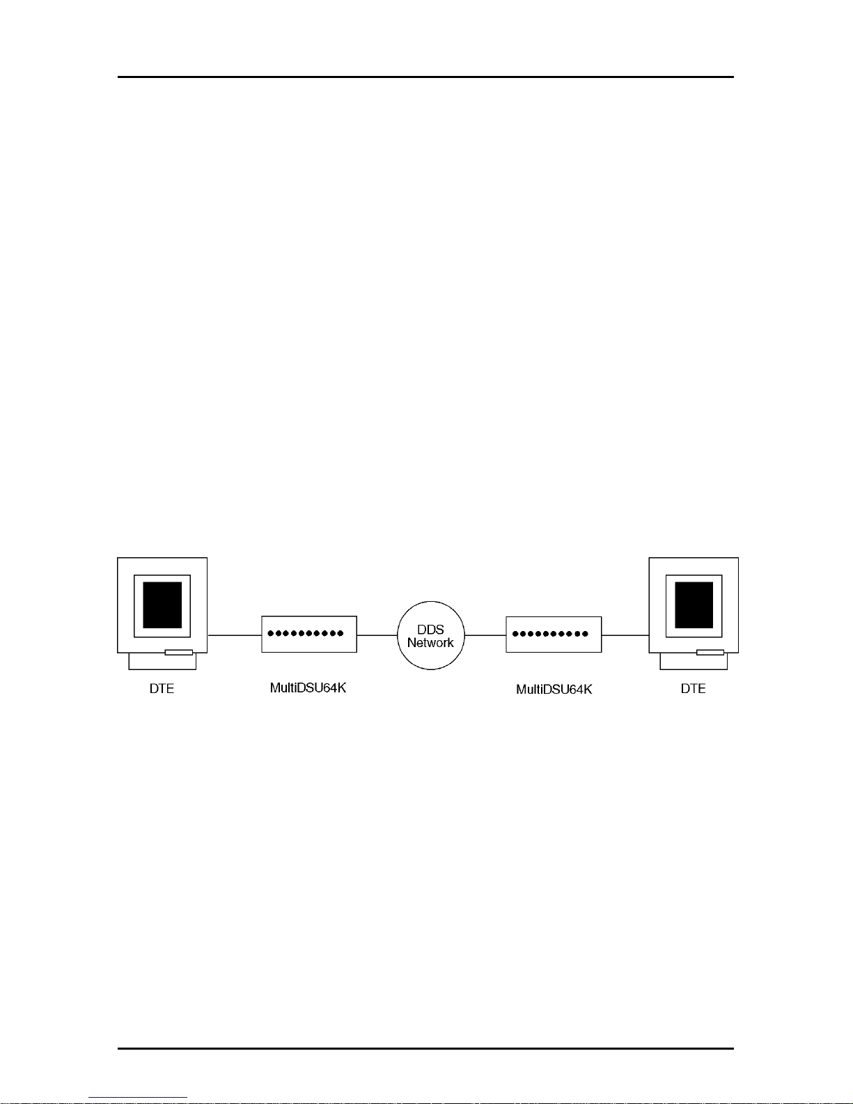
DDS POINT-TO-POINT APPLICATION
In this application, the MultiDSU64K provides the interface between
the DDS line and the DTE at your site. Your network provider will
provide (at your request) a DDS line connecting the desired
locations. The figure below depicts a sample DDS Point-to-point
application.
Figure B-1. DDS Point-to-Point Application
DDS MULTIPOINT (POLLED) APPLICATION
Since your Central Office (CO) equipment must include “Multipoint
Junction Units” (MJUs) and other special arrangements for this type
of service, you may need to coordinate efforts with your network
service provider.
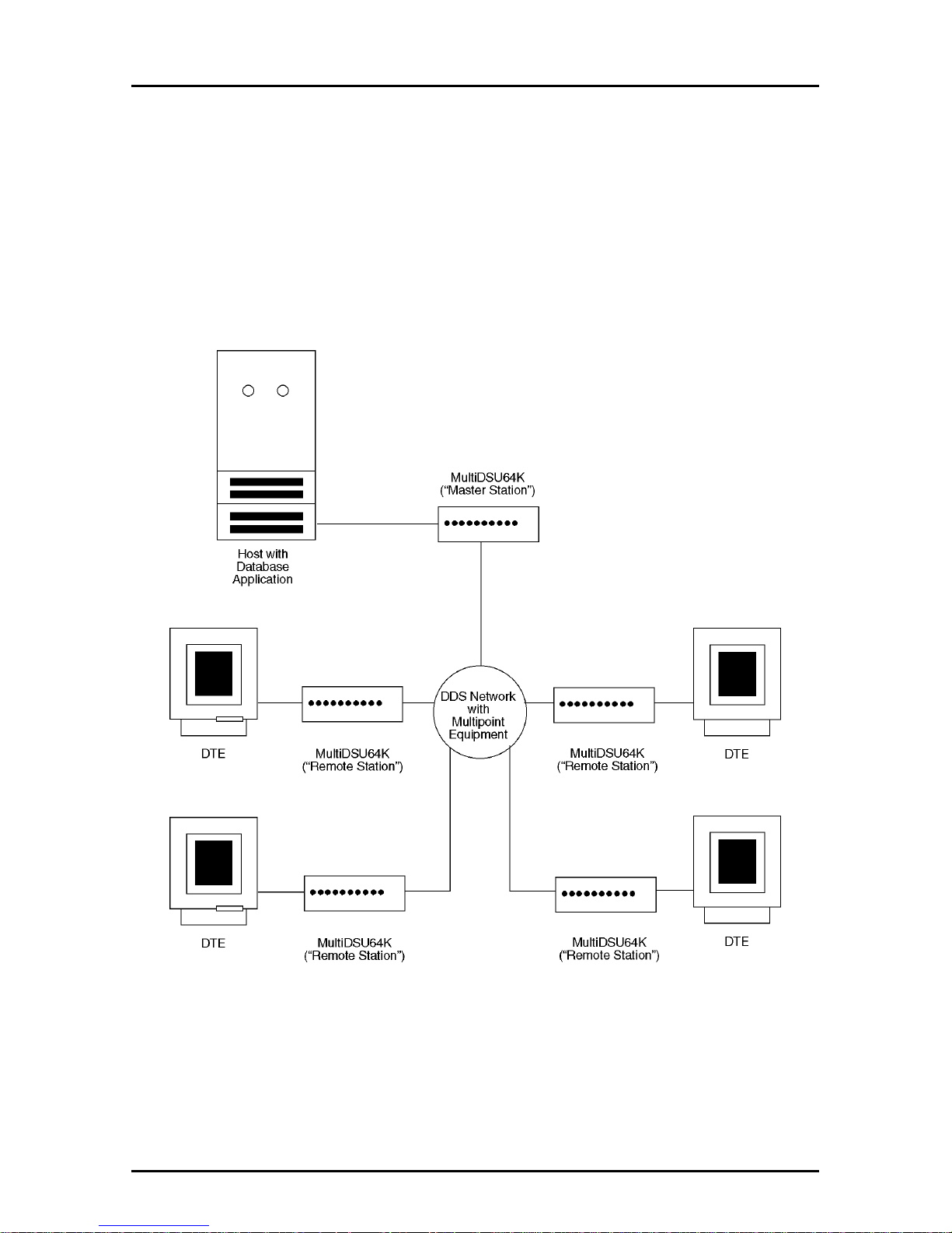
The MultiDSU64K at the host end is the Master Station (also called
the “Control Station”), which typically has RTS forced on. The
attached MultiDSU64Ks are called “Remote Stations” and have RTS
controlled by the DTE.
Page 52
52
MT64DSU Owner's Manual
Multipoint DDS provides communication between a control station
and two or more remote stations. All data transmitted by the control
station is sent to each remote station. For data transmitted from the
remote stations, the MJUs combine bit streams from the remote
stations into a single, serial bit stream sent to the control station. All
stations on the same multipoint circuit must run at the same bit rate
(any of the DDS customer service rates).
The figure below shows a typical Multipoint (Polled) application.
Figure B-2. DDS Multipoint Polled Application
Page 53
53
Appendixes
LOCAL AREA DATA SET APPLICATION
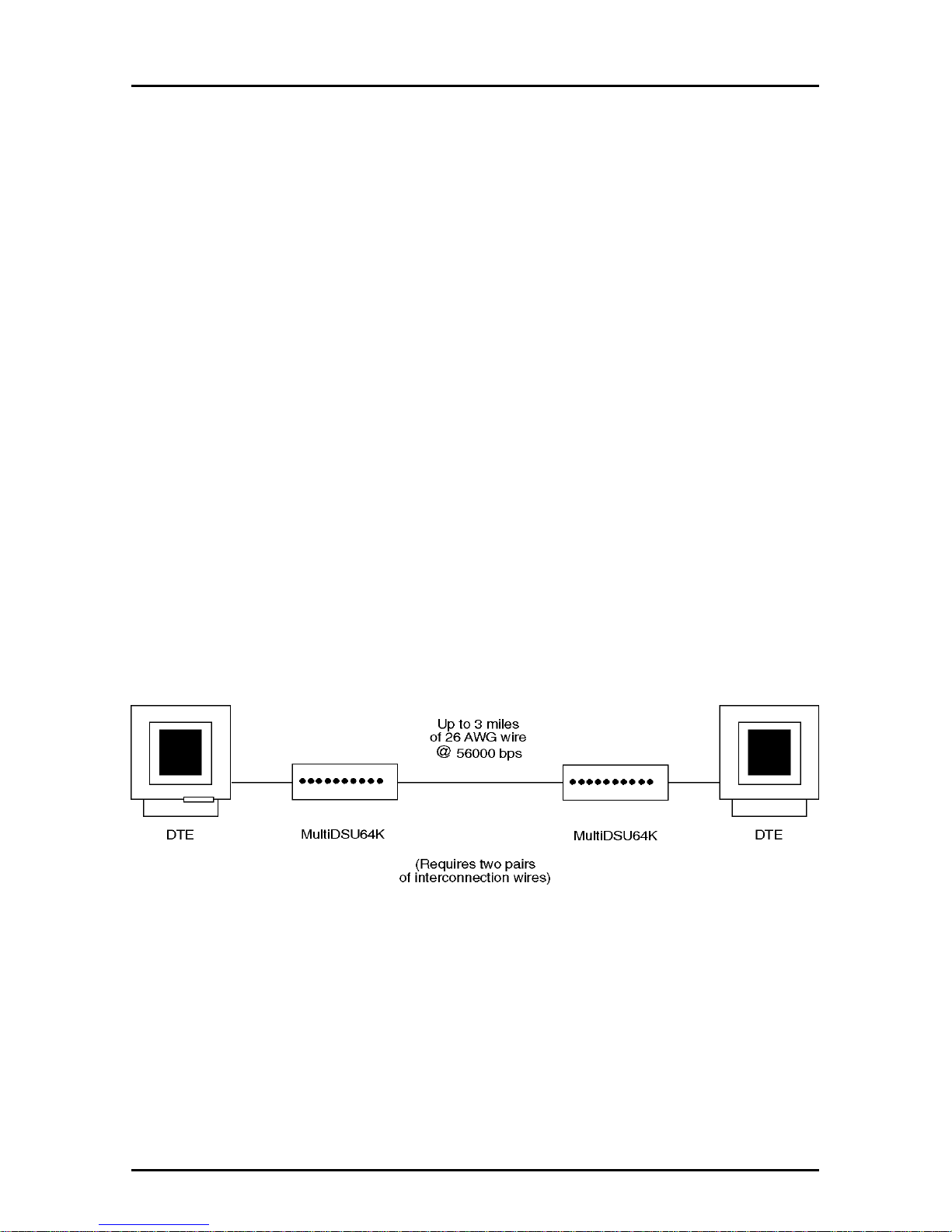
Your MultiDSU64K can be used as a point-to-point LADS (Local
Area Data Set) at transmission speeds of 2400, 4800, 9600, 19200,
56000 or 64000 bps over 4-wire, non-loaded metallic wire pairs. The
installation of the MultiDSU64K in a LADS application is the same
as for DDS applications, except for the timing (Clocking) setting.
LADS applications require one MultiDSU64K to be set for Internal
timing and the other MultiDSU64K to be set for DDS timing (refer to
Chapter 2 of this manual). The network cable connection requires
“cross-over”
wiring; the transmit pair of each MultiDSU64K must be
connected to the receive pair of the far-end MultiDSU64K.
The MultiDSU64K uses 4-wire non-loaded metallic circuits for LADS
applications. The table below outlines approximations for the
maximum cable length for limited distance applications.
Data Rate Wire Gage
19 AWG 22 AWG 24 AWG 26 AWG
56000 bps 10.0 6.0 4.2 3.0 miles
64000 bps 7.8 4.7 3.3 2.3 miles
The figure below depicts a typical Local Area Data Set application.
Figure B-3. Local Area Data Set Application
Page 54
54
MT64DSU Owner's Manual
EXTERNAL CLOCKING APPLICATION
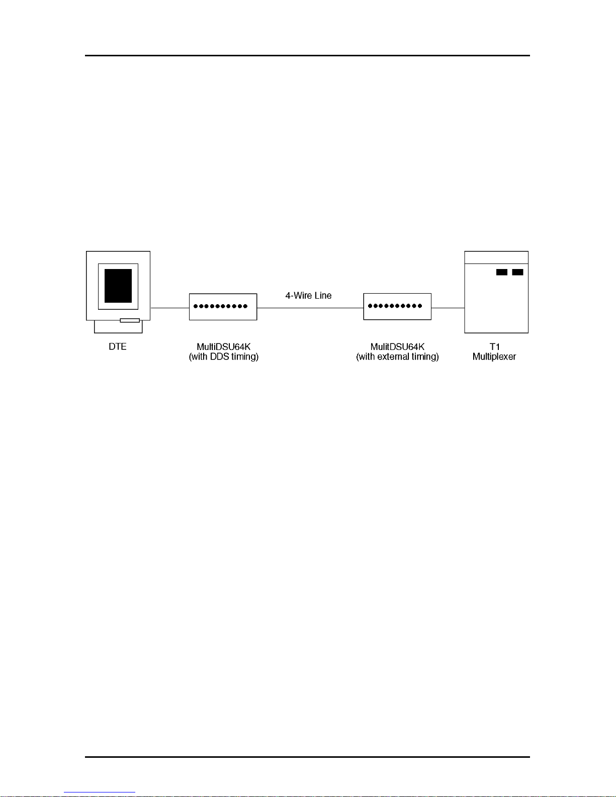
This application is similar to the Local Area Data Set application
except for the timing option setting. In the example below, the DTE
connector of the T1 mux is connected to the DTE connector of the
MultiDSU64K. Here, the MultiDSU64K must receive timing
information from the T1 mux. The MultiDSU64K is set for external
timing in this type of application. At the DTE end, DDS timing is
selected, providing normal clocking to the DTE.
The figure below shows a typical External Clocking application.
Figure B-4. External Clocking Application
ANALOG OFF-NET EXTENSION APPLICATION
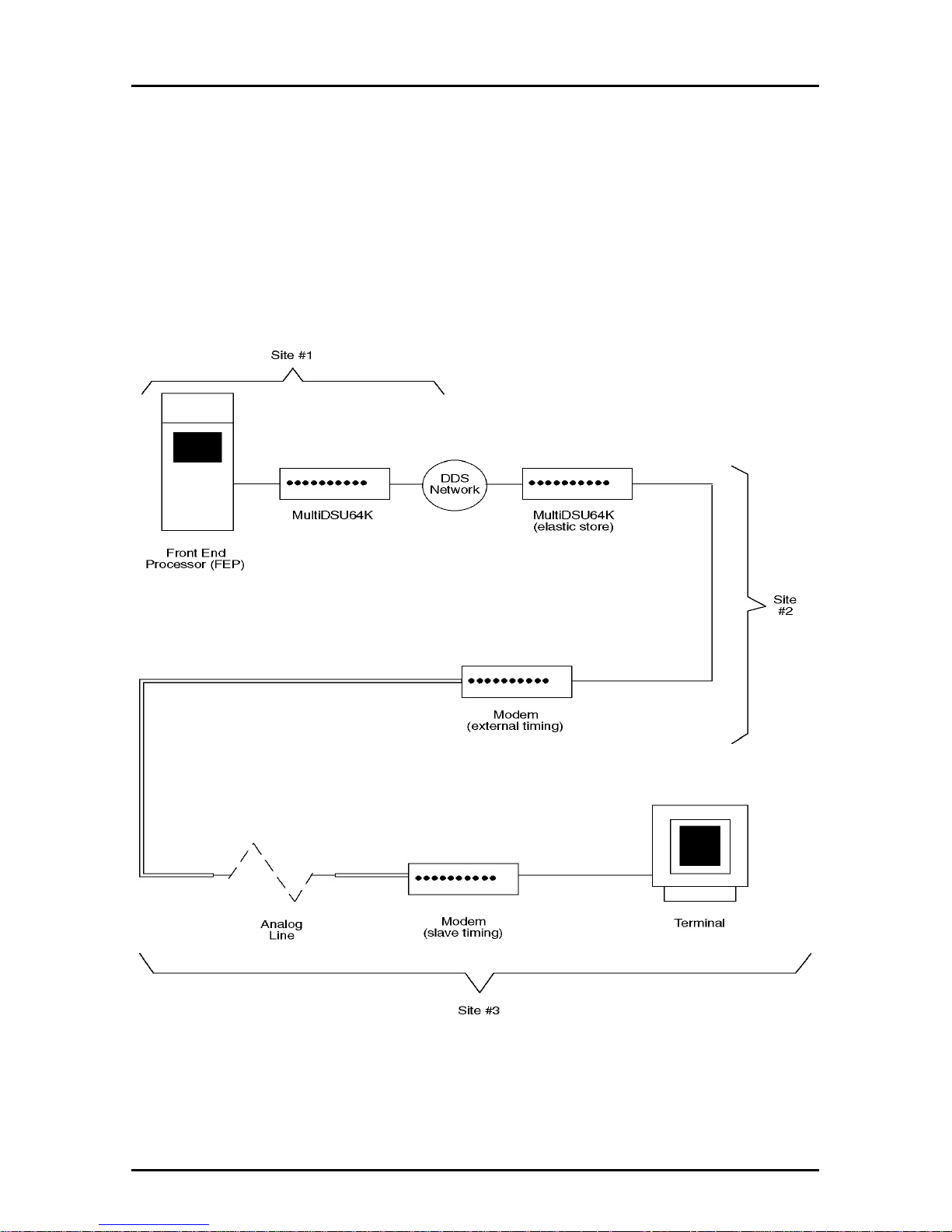
In this application, the MultiDSU64K is used with conventional
analog modems and lines to complete DDS circuits in an area where
DDS is not available, or where the customer requires an extension
of the DDS circuit for a special application.
In applications using the MultiDSU64K for an off-net extension, one
MultiDSU64K may be set for External Timing and the other set for
DDS Timing; however, in this application, the clock (timing) being
supplied must be accurate to +/-0.008% of the enabled data
transmission rate.
The Elastic Store option is used in off-net extension applications
with analog modems to compensate for small timing phase drifts
that typically occur in such applications. A
“cross-over”
cable is
required to connect the MultiDSU64K DCE connector to the analog
modem in this application (see Appendix C).
Page 55
55
Appendixes
The analog modem at the same end as the MultiDSU64K must have
External Timing enabled; the modem at the end of the off-net
extension must have DDS Timing enabled.
In MultiDSU64K applications that use controlled carrier, the CTS
delay for the analog modem at the end of the off-net extension must
be longer than the CTS delay of the MultiDSU64K.
Figure B-5. Analog Off-Net Extension Application
Page 56
56
MT64DSU Owner's Manual
Appendix C - Interface Signals and Connector
Pinouts
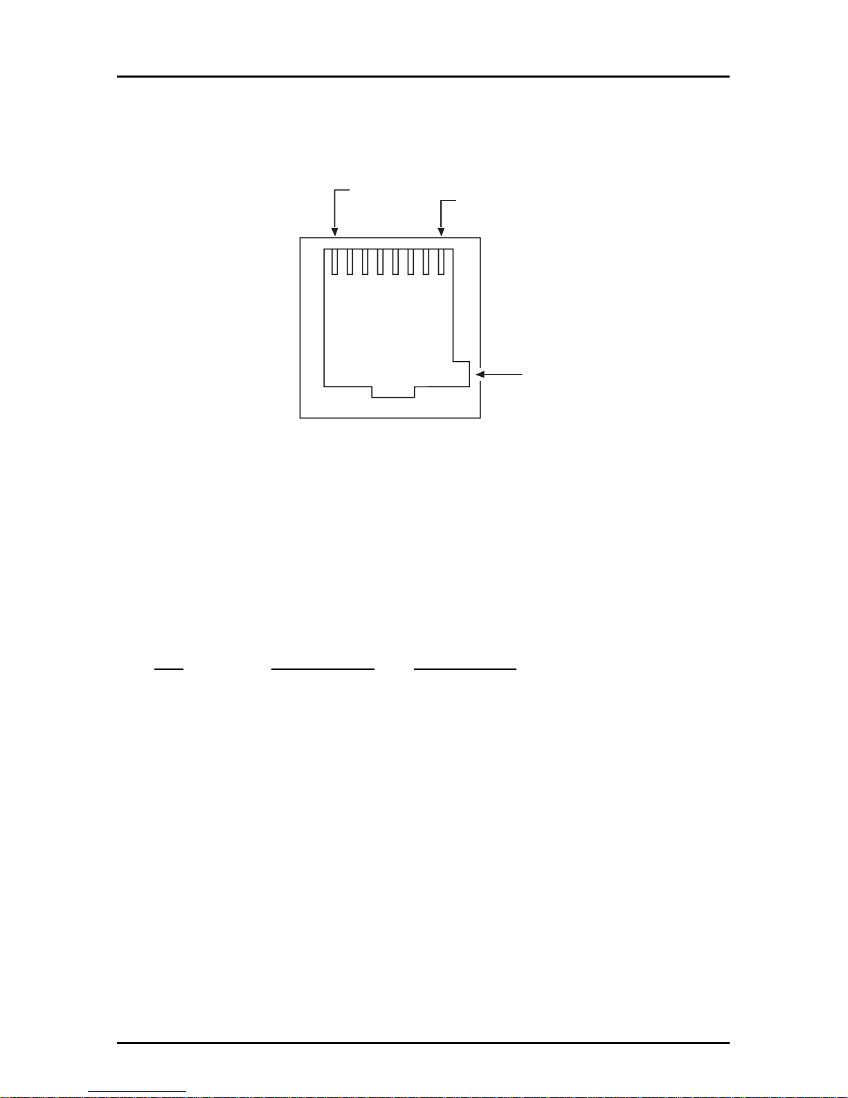
DDS RJ48S CONNECTOR
Pin 1
Pin 8
Key
Figure C-1. RJ48S Connection
DESCRIPTION
This connector ties the MultiDSU64K to the DDS Network.
PIN IDENTIFICATION
Pin Description Destination
1 N/C N/C
2 N/C N/C
3 N/C
4 Transmit To Line
5 Receive From Line
6 N/C
7 N/C N/C
8 N/C N/C
Page 57
57
Appendixes
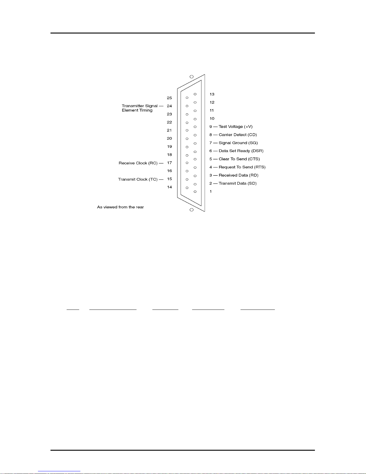
RS-232C DB25S CONNECTOR
Figure C-2. RS-232 Connection
DESCRIPTION
This connector ties the MultiDSU64K to the DTE. The DB25S
connector has the following pinout configuration.
PIN IDENTIFICATION
Pin Description Circuit Source Function
2 Transmit Data SD DTE Transmitted Data
3 Received Data RD DCE Received Data
4 Request to Send RTS DTE Request to Send
5 Clear To Send CTS DCE Clear to Send
6 Data Set Ready DSR DCE Data Set Ready
7 Signal Ground SG -- Signal Ground
8 Carrier Detect CD DCE Carrier Detect
9 Test Voltage +V DCE Test Voltage
15 Transmit Clock TC DCE Transmit Clock
17 Receive Clock RC DCE Receive Clock
24 Transmitter Timing XTC DTE External
Transmit Clock
Page 58
58
MT64DSU Owner's Manual
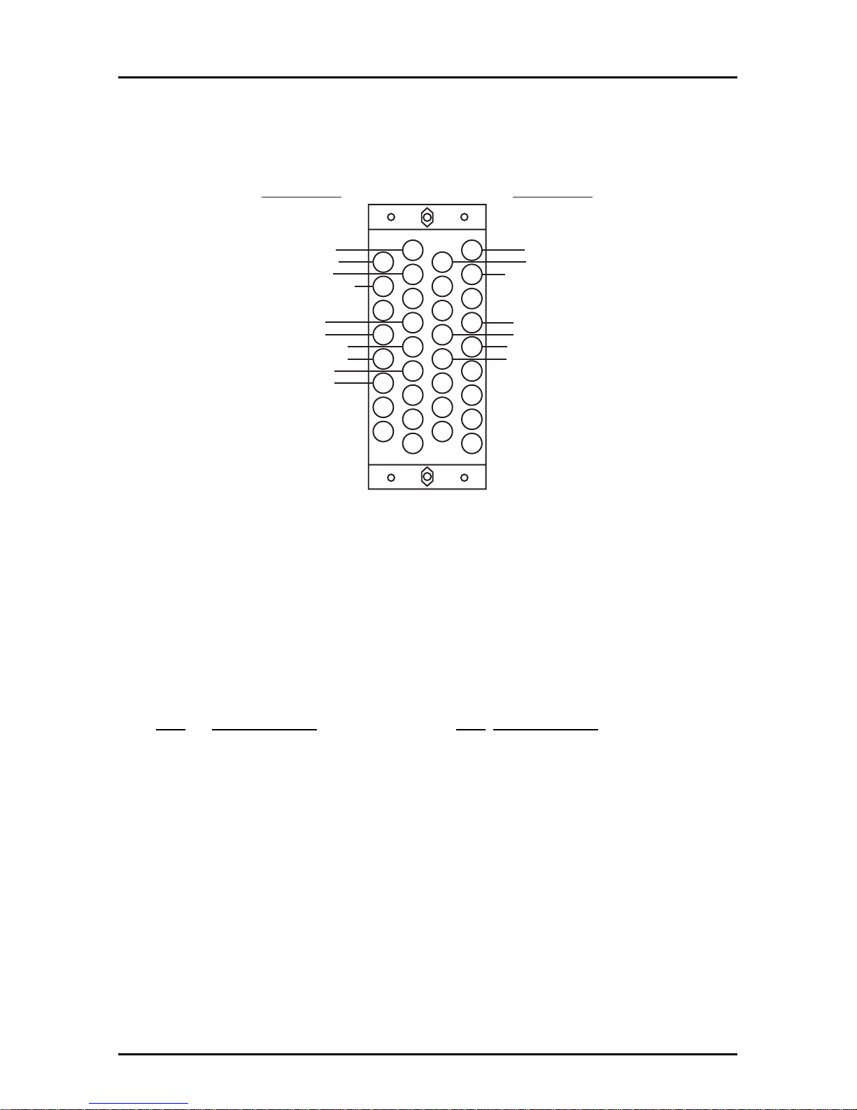
V.35 34-PIN CONNECTOR
C
H
M
S
W
AA
EE
KK
D
J
N
T
X
BB
FF
LL
A
E
K
P
U
Y
CC
HH
MM
B
F
L
R
V
Z
DD
JJ
NN
V.35 34-PIN CONNECTOR
Signal Designation Signal Designation
Chassis Ground
Request To Send
Data Set Ready
Data Terminal Ready
Send Data (A)
Send Data (B)
Terminal T iming (A)
Terminal T iming (B)
Send Timing (A)
Send Timing (B)
Signal Ground
Clear To Send
Data Carrier Detect
Receive Data (A)
Receive Data (B)
Receive Timing (A)
Receive Timing (B)
As viewed from the connector side
Figure C-3. V.35 Connection
DESCRIPTION
This connector ties the MultiDSU64K to the DTE. The V.35
connector has the following pinout configuration.
PIN IDENTIFICATION
Pin Description Pin Description
A Chassis Ground R Received Data (A)
B Signal Ground T Received Data (B)
C Request To Send Y Transmit Clock (A)
D Clear To Send AA Reansmit Clock (B)
E Data Set Ready V Receive Clock (A)
F Rec. Line Signal Detect X Receive Clock (B)
H Data Terminal Ready U External Transmit Clock (A)
P Transmitted Data (A) W External Transmit Clock (B)
S Transmitted Data (B)
Page 59
59
Appendixes
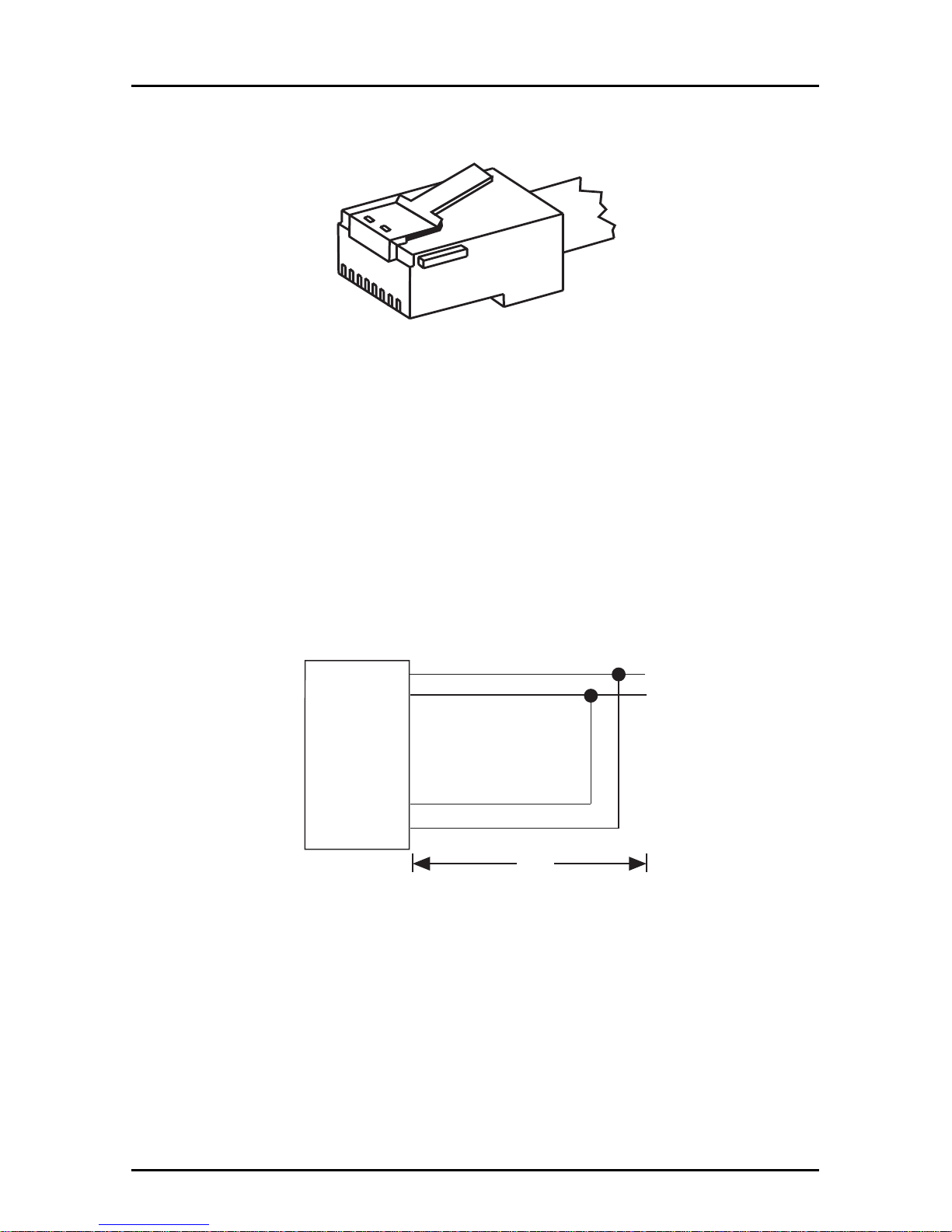
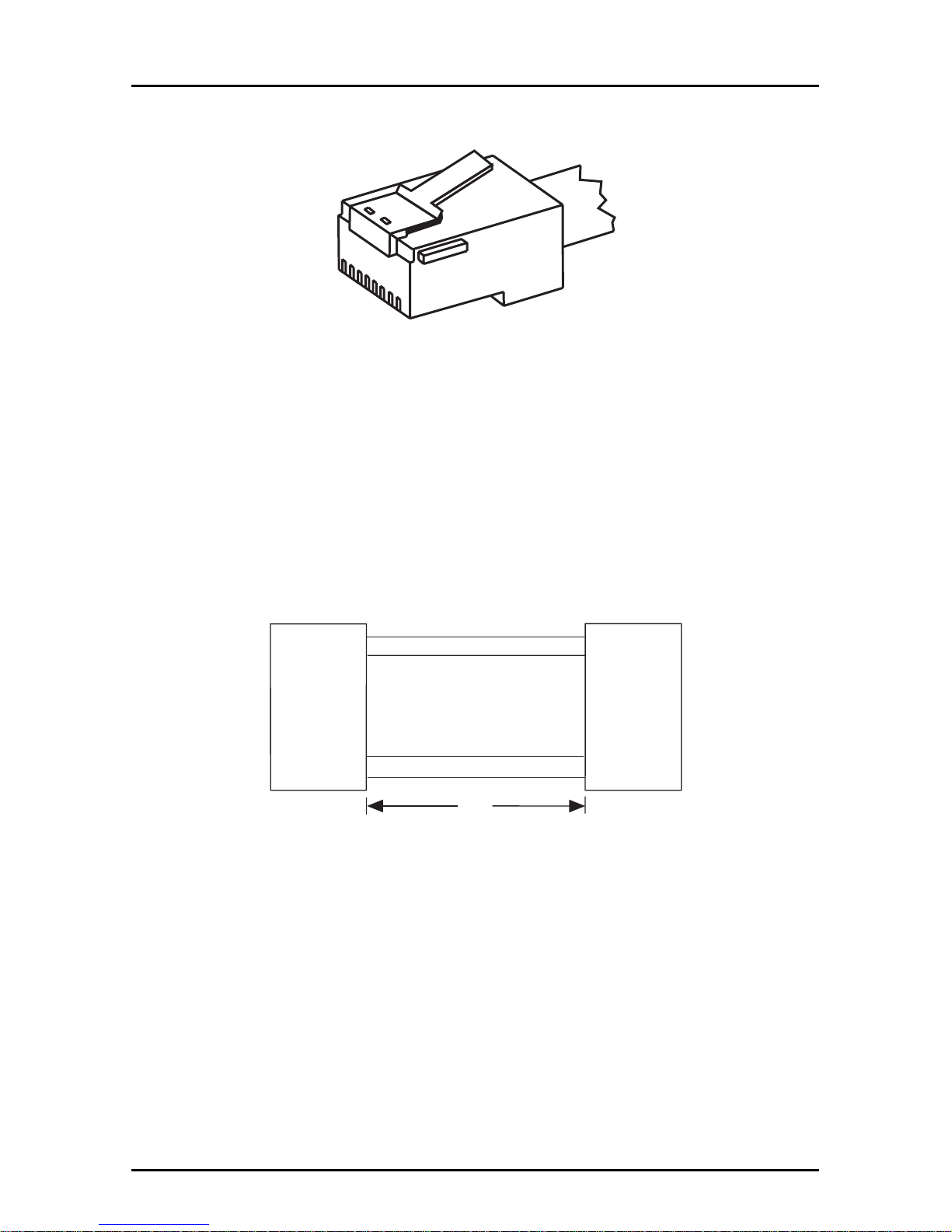
LOOPBACK CABLE
1
8
Figure C-4. Loopback Cable
DESCRIPTION
This cable lets you test the MultiDSU64K when a second DSU is not
available. It tests the DSU by having the DSU generate a signal,
then the cable
“loops”
the signal back to the DSU for comparison to
the original signal sent. You can order this cable (#45640100) from
Multi-Tech, or build one using the instructions below.
SCHEMATIC
RJ48S
1
2
3
4
5
6
7
8
6"
RECEIVE
RECEIVE
TRANSMIT
TRANSMIT
BUILD INSTRUCTIONS
1. Strip cable insulation 3/4"
2. Cut wires 3, 4, 5, 6 off.
3. Strip wires 1, 2, 7, 8 1/4"
4. Solder wires 1 and 8 together.
5. Solder wires 2 and 7 together.
6. Cover solder connections with 1" of shrink tube.
Page 60
60
MT64DSU Owner's Manual
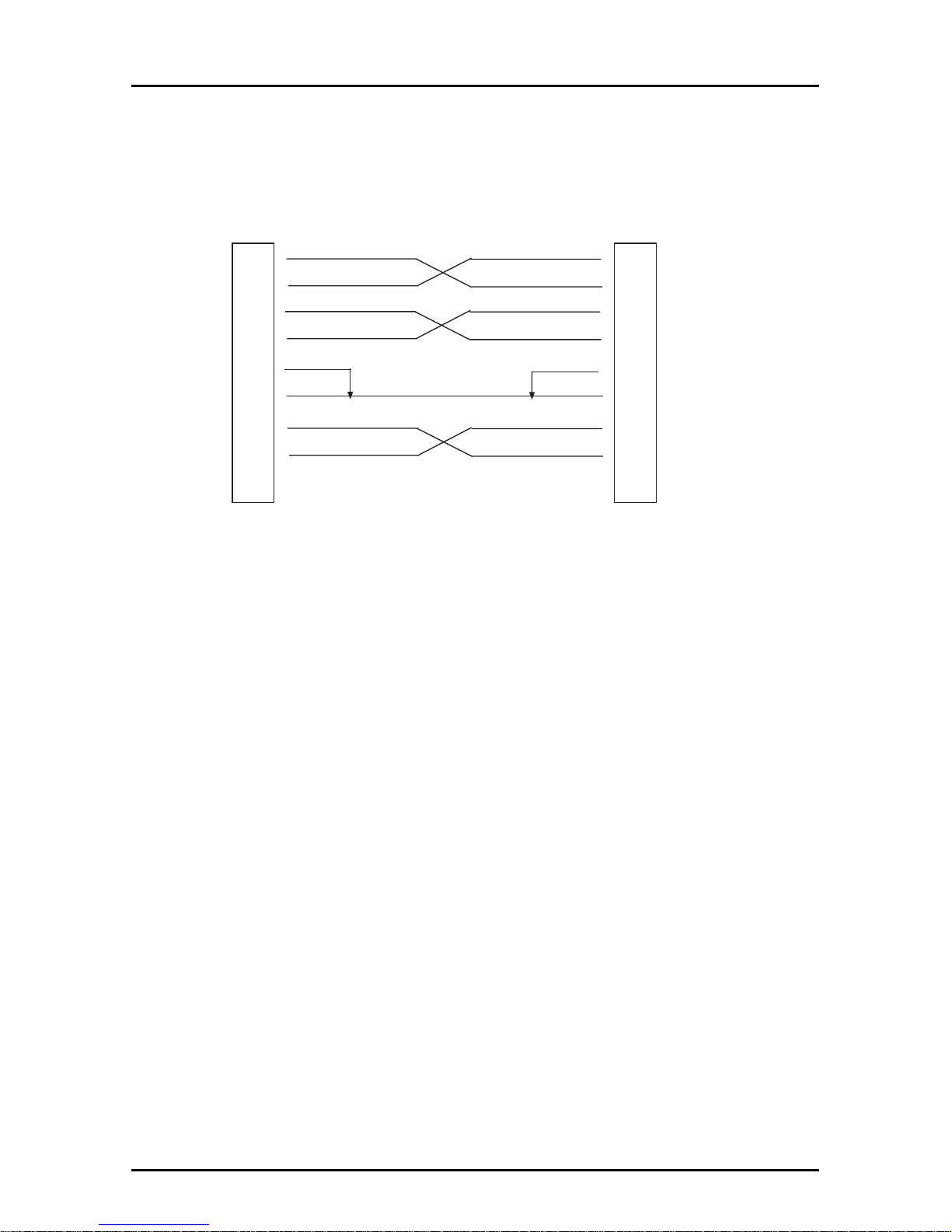
BACK-TO-BACK CABLE
1
8
Figure C-5. Back-to-Back Cable
DESCRIPTION
This cable lets you test a suspect DSU by connecting it to a known
good DSU. It tests the suspect DSU by connecting its Transmit
signal to the good DSUs Receive circuits. You can order it from
Multi-Tech (#45050000), or build one using the instructions below.
Refer to Chapter 4 for test procedures.
SCHEMATIC
RJ48S
1
2
3
4
5
6
7
8
7"
RJ48S
8
7
6
5
4
3
2
1
BUILD INSTRUCTIONS
1. Strip cable installation 3/4".
2. Strip wires 1,2,7 and 8 on one end of cable and 8,7,2 and 1 on
other end 1/4".
3. Cut unstripped wires off.
4. Solder wire 1 on one connector to 8 on the other.
5. Solder wire 2 on one connector to 7 on the other.
6. Solder wire 7 on one connector to 2 on the other.
7. Solder wire 8 on one connector to 1 on the other.
8. Cover solder connections with 1" of shrink tube.
Page 61
61
Appendixes
CROSSOVER CABLE
Modem
(DCE)
DSU
(DCE)
TxD
RxD
RTS
CTS
DSR
GND
CD
DTR
RI
2
3
4
5
6
7
8
20
22
2
3
4
5
6
7
8
20
22
TxD
RxD
RTS
CTS
DSR
GND
CD
DTR
RI
Male
Male
Figure C-6. Crossover Cable
In applcations using the MULTIDSU64K for an off-net extension a
“cross-over”
cable is required to connect the MultiDSU64K DCE
connector to the analog modem in this application.
Page 62

62
MT64DSU Owner's Manual
Appendix D - DIP-Switch Summary
Synchronous
DIP-Switch Effect
Sync Speeds
9.6K 19.2K 56K 64K
#1 DN UP *DN UP
#2 DN DN *UP UP
Internal External DDS
#3 UP UP *DN
#4 UP DN *DN
#5 UP Asynchronous Mode On
*DN Synchronous Mode On
#6 UP RTS Controlled by DTE
*DN RTS Forced On
#7 UP DSR Controlled by DSU
*DN DSR Forced On
#8 UP Local Loopback (to DTE)
*DN Normal
Asynchronous
DIP-Switch Effect
Sync Speeds
9.6K 19.2K 38.4K 57.6K
#1 DN UP *DN UP
#2 DN DN UP UP
#9 UP Digital Loopback (to Line)
*DN Normal
#10 UP Remote Loopback
*DN Normal
#11 UP Test Pattern Enabled
*DN Normal
#12 UP Elastic Store Enabled
*DN Elastic Store Disabled
#13 UP This switch must be DOWN.
*DN
#14 UP Switched Line
*DN Dedicated Line
#15 UP DTR Controlled by DTE
*DN DTR Forced On
*Factory Default Setting
Page 63

63
Appendixes
Appendix E - FCC Regulations for Telephone Line
Interconnection
1. This equipment complies with Part 68 of the Federal
Communications Commission (FCC) rules. On the outside
surface of this equipment is a label that contains, among other
information, the FCC registration number and ringer
equivalence number (REN). If requested, this information must
be provided to the telephone company.
2. As indicated below, the suitable jack (Universal Service Order
Code connecting arrangement) for this equipment is shown. If
applicable, the facility interface codes (FIC) and service order
codes (SOC) are shown. An FCC-compliant telephone cord and
modular plug is provided with this equipment. This equipment is
designed to be connected to the telephone network or premises
wiring using a compatible modular jack which is Part 68
compliant. See installation instructions for details.
3. The ringer equivalence number (REN) is used to determine the
quantity of devices which may be connected to the telephone
line. Excessive RENs on the telephone line may result in the
devices not ringing in response to an incoming call. In most, but
not all areas, the sum of the RENs should not exceed five (5.0).
To be certain of the number of devices that may be connected
to the line, as determined by the total RENs, contact the
telephone company to determine the maximum REN for the
calling area.
4. If this equipment causes harm to the telephone network, the
telephone company will notify you in advance. But if advance
notice isn’t practical, the telephone company will notify the
customer as soon as possible. Also, you will be advised of your
right to file a complaint with the FCC if you believe it is
necessary.
5. The telephone company may make changes in its facilities,
equipment, operations, or procedures that could affect the
operation of the equipment. If this happens, the telephone
company will provide advance notice in order for you to make
necessary modifications in order to maintain uninterrupted
service.
Page 64

64
MT64DSU Owner's Manual
6. If trouble is experienced with this equipment (see model
indicated below) please contact Multi-Tech Systems, Inc. at the
address shown below for details on how to have repairs made.
If the trouble is causing harm to the telephone network, the
telephone company may request you remove the equipment
from the network until the problem is resolved.
7. No repairs are to be made by you. Repairs are to be made only
by Multi-Tech Systems or its licensees. Unauthorized repairs
void registration and warranty.
8. This equipment cannot be used on public coin service provided
by the telephone company. Connection to Party Line Service is
subject to state tariffs. (Contact the state public utility
commission, public service commission or corporation
commission for information.)
9. If so required, this equipment is hearing-aid compatible.
Manufacturer: Multi-Tech Systems, Inc.
Trade Name: MultiDSU64K
Model Number MT64DSU
FCC Registration #: AU7USA-18883-DE-N
Ringer Equivalence: N/A
SOC Codes: 6.0N
Modular Jack RJ48S for 4-wire connection
Service Center in USA: Multi-Tech Systems Inc.
2205 Woodale Drive
Mounds View, MN 55112
(612) 785-3500/(800) 328-9717
FAX (612) 785-9874
Page 65

65
Index
Index
A
About This Manual 7
Action Commands 41
ANALOG OFF-NET EXTENSION
APPLICATION 54
Analog Off-Net Extension Applica-
tion 55
Application Examples 51
Async data bits 43
Async DTE Dialing 44
Asynchronous/Synchronous Opera-
tion 18
Auto-Answer 42
Auto-Disconnect 42
B
Back-to Back Cable 60
Basic DSU/CSU Configuration 8
C
Certification 12
Clear Number in Memory (CLA)
Command 49
Compatibility 12
CompuServe/Internet 36
Configuration Commands 40
D
Data Bits (S12) 46
Introduction and Description 7
Data Set Ready 19
Dedicated/Switched Line Opera-
tion 20
Default Settings (&F) 47
Dial Phone Number Provided (CRN)
Command 48
Dial Phone Number Stored in Memory
(CRS) Command 48
Digital Interface 12
Digital Loopback Test 19
Dimensions 12
DIP-Switch Summary 62
Disregard or Connect to Incoming Calls
(DIC or CIC 49
DSR Control 43
DSU Loopback Test with Loopback
Cable 22
DTE Dialing (S15) 47
DTE Dialing (S2) 46
DTE Interface Mode 43
DTR Forcing 20
E
Echo Canceler Tone 43
Elastic Store 19
F
FIC Codes 12
Figure A-2. DDS Multipoint Polled
Application 52
H
How to Commands 40
I
Input Impedance 12
Installation, Connection and Default 7
Interface Signals and Connector
Pinouts 56
Interfaces 12
Internal/External/DDSClocking 17
Page 66

66
MT64DSU Owner's Manual
L
Limited Warranty
On-line Warranty Registration 32
Listing Numbers Stored in Memory
(RLN) Command 49
Local Area DataA Set Application 53
Loopback Cable 59
M
Model Number 11
Modulation 12
MultiDSU64K Back Panel 14, 15
MultiDSU64K PC Circuit Board 16
Multipoint (Polled) Application 51, 52
N
Number of Redials 42
O
On-line Warranty Registration 32
Output Impedance 12
P
Param Download (*W) 47
Param Lock (S19) 47
Parameter Lock 44
Parity (S14) 46
Point-to-Point Application 51
Power 14
Power Requirements 12
Power supply 15
R
Receive Levels 12
Recording MultiDSU64K Informa-
tion 33
Request To Send Forced 18
RS232 Connection 56, 57
RTS Control 43
RTS Delay 12
S
SDLC/BSC Option 19
Speed Switches 17
Stop Bits (S13) 46
Store a Phone Number in Memory
(PRN) Command 48
Sync DTE Dialing 42
System Reset (*R) 47
T
Temperature 12
Terse/Verbose 45
Transmit Level 12
U
USOC Jack 12
V
V .25bis Auto-Dial (S16) 46
V.35 Connection 58
W
Warranty 32
What is in Your MultiDSU64K Pack-
age? 14
 Loading...