

Multitech MT56DSU-R, MultiDSU56K Owner's Manual

TM
MultiDSU56K
Rack Mount Multi-Rate DSU
Model MT56DSU-R
Owner's Manual
82023101.p65 2/12/01, 2:52 PM1

Owners Manual
P/N 82023101, Rev. B
Model No. MT56DSU-R
This publication may not be reproduced, in whole or in part, without prior
expressed written permission from Multi-Tech Systems, Inc. All rights
reserved.
Copyright © 1995, by Multi-Tech Systems, Inc.
Multi-Tech Systems, Inc. makes no representations or warranties with
respect to the contents hereof and specifically disclaims any implied
warranties of merchantability or fitness for any particular purpose. Furthermore, Multi-Tech Systems, Inc. reserves the right to revise this
publication and to make changes from time to time in the content hereof
without obligation of Multi-Tech Systems, Inc. to notify any person or
organization of such revisions or changes.
Record of Revisions
Revision Description
A Manual released. All pages at Revision A.
(06/07/93)
B Manual revised to change cable port numbers and
build
(01/09/95) instructions
Trademarks
Multi-Tech and the Multi-Tech logo are trademarks of Multi-Tech Systems, Inc.
DATAPHONE® is a registered trademark of AT&T.
Multi-Tech Systems, Inc.
2205 Woodale Drive
Mounds View, Minnesota 55112 USA
(612) 785-3500 or (800) 328-9717
Fax 612-785-9874
Tech Support (800) 972-2439
BBS (612) 785-9875 or (800) 392-2432
82023101.p65 2/12/01, 2:52 PM2

Contents
Chapter 1 - Introduction and Description
1.1 Introduction ............................................................................... 6
1.2 About This Manual ................................................................... 6
1.3 Description ................................................................................ 7
1.4 CSU/DSU Basics ..................................................................... 8
1.4.1 DSU Functions .............................................................. 8
1.4.2 CSU Functions .............................................................. 8
1.5 Features .................................................................................... 9
1.6 FCC Regulations for Telephone Line Interconnection ..... 10
1.7 Specifications.......................................................................... 12
Chapter 2 -Hardware Installation
2.1 Introduction ............................................................................. 16
2.2 Default DIP Switch and Jumper Settings ........................... 16
2.2.1 12 -Position DIP Switch (# 1-12) .............................. 17
2.2.2 4-Position DIP Switch (# 13-16) ............................... 17
2.2.3 RS232/V.35 Shunt ....................................................... 17
2.3 Changing the Default DIP Switch Settings ........................ 18
2.4 Installation Procedure ........................................................... 20
Chapter 3 - Operation
3.1 Introduction ............................................................................. 24
3.2 Options .................................................................................... 24
3.2.1 Data Rate ..................................................................... 24
3.2.2 Async/Sync .................................................................. 24
3.2.3 Anti-Streaming ............................................................. 25
3.2.4 Elastic Store ................................................................. 25
3.2.5 System Status.............................................................. 26
3.2.6 Circuit Assurance ........................................................ 2 6
3.2.7 Clocking ........................................................................ 27
3.2.8 RTS Forced On ........................................................... 27
3.2.9 DSR Forced On ........................................................... 28
3.2.10 Async Word Length .................................................... 28
82023101.p65 2/12/01, 2:52 PM3
iii

3.2.11 Normal/Diagnostics ..................................................... 28
3.3 LED Indicators ........................................................................ 29
3.4 Functions ................................................................................. 29
3.4.1 Local Area Data Set Applications ............................. 29
3.4.2 Off-Net Extension Applications ................................. 30
Chapter 4 - Troubleshooting
4.1 Introduction ............................................................................. 32
4.2 LED Indicators ........................................................................ 32
4.2.1 RCV Indicator .............................................................. 33
4.2.2 XMT Indicator ............................................................... 3 3
4.2.3 CD Indicator ................................................................. 33
4.2.4 56K Indicator ................................................................ 33
4.2.5 19.2 Indicator ............................................................... 33
4.2.6 CTS Indicator ............................................................... 33
4.2.7 RTS Indicator ............................................................... 34
4.2.8 NS Indicator ................................................................. 34
4.2.9 TM Indicator ................................................................. 34
4.2.10 OOS Indicator .............................................................. 3 4
4.3 Diagnostic Tests ..................................................................... 35
4.3.1 Local Loopback Test ................................................... 35
4.3.2 Digital Loopback Test ................................................. 36
4.3.3 Digital Loopback With Test Pattern Test.................. 37
4.3.4 Test Pattern Test.......................................................... 38
4.3.5 DSU Loopback Test .................................................... 3 9
4.3.6 DSU Back-to-Back Test ............................................. 40
Chapter 5 - Warranty, Service and Tech Support
5.1 Service ..................................................................................... 42
5.2 Limited Warranty .................................................................... 4 2
5.3 Tech Support and BBS.......................................................... 43
5.4 Recording DSU Information ................................................. 4 3
Appendixes
Appendix A - Application Examples ............................................... 46
Appendix B - Interface Signals and Connector Pinouts ............. 50
Glossary
iv
82023101.p65 2/12/01, 2:52 PM4

TM
MultiDSU56K
Chapter 1 - Introduction and Description
82023101.p65 2/12/01, 2:52 PM5

MT56DSU-R Owner's Manual
1.1 Introduction
Congratulations! Your new MT56DSU-R is one of the finest DSU/
CSUs available today. As a combined CSU (Channel Service Unit)
and DSU (Data Service Unit), it provides a direct connection to the
DATAPHONE
®
Digital Service (DDS) network. The MT56DSU-R
connects a computer or Data Terminal Equipment (DTE) to remote
equipment using DDS network lines at 2400, 4800, 9600, 19200 and
56000 bps speeds for point-to-point and multi-point service.
1.2 About This Manual
This manual contains five chapters and two appendixes. In addition,
there is a Glossary and an Index at the end of this manual. The
information in this manual is provided as described below.
Chapter 1 - Introduction and Description contains an introduction
to the MT56DSU-R product and its features and functions.
Chapter 2 - Hardware Installation provides configuration and
installation procedures.
Chapter 3 - Operation describes the functional features and options
of the MT56DSU-R.
Chapter 4 - Troubleshooting explains what to do if your
MT56DSU-R encounters problems in operation.
Chapter 5 - Service, Warranty and Tech Support defines
procedures to follow if the troubleshooting steps in Chapter 4 do not
fix the problem.
Appendix A - Applications Examples illustrates several DSU/CSU
uses that may help in understanding your particular installation site.
Appendix B - Interface Signals lists the various electronic signals
and connector pinouts related to the MT56DSU-R.
6
82023101.p65 2/12/01, 2:52 PM6

Chapter 1 - Introduction and Description
1.3 Description
The MT56DSU-R is a rack-mounted DSU/CSU that is easy to
operate and has the features to allow flexibility in meeting your
transmission requirements. The DDS is a service for transmission of
digital signals via digital transmission facilities exclusively. The
MT56DSU-R is designed to meet AT&T Technical Publication 62310
requirements. As such, the MT56DSU-R provides all of the functions
required on the customer side of the network.
The MT56DSU-R provides user selection of synchronous data
communications at rates of 2400, 4800, 9600, 19200 and 56000
bps, and asynchronous data communications rates up to 19200
bps. It provides three separate interface connections (RS232C, V.35
and DDS).
You will find the MT56DSU-R easy to install, use and maintain. It is
recommended that you read the entire manual early in your
experience with the MT56DSU-R so you can appreciate all of the
MT56DSU-R features and options.
82023101.p65 2/12/01, 2:52 PM7
7
MT56DSU-R Owner's Manual
1.4 CSU/DSU Basics
A DSU (Data Service Unit) and a CSU (Channel Service Unit) are
typically connected to provide the interface between a DTE (data
terminal equipment) and the DDS (Digital Data Service) or other
four-wire network.
The DSU is used to process serial synchronous or asynchronous
digital data over the DDS network or other four-wire unloaded
twisted-pair wiring network.
The MT56DSU-R can transmit data at 56000, 19200, 9600, 4800
and 2400 bps in multi-point and point-to-point applications.
The MT56DSU-R contains the functions of a Data Service Unit
(DSU) and a Channel Service Unit (CSU) in a single package.
1.4.1 DSU Functions
The DSU encodes data as pulses on the communications line by
converting the customer data stream to bipolar format for
transmission over the digital network.
1.4.2 CSU Functions
The CSU is used to terminate the digital circuit at the customer site.
It performs line conditioning functions, ensures network compliance
with FCC rules, and responds to test commands (either from the
telco central office (CO) or from the CSU).
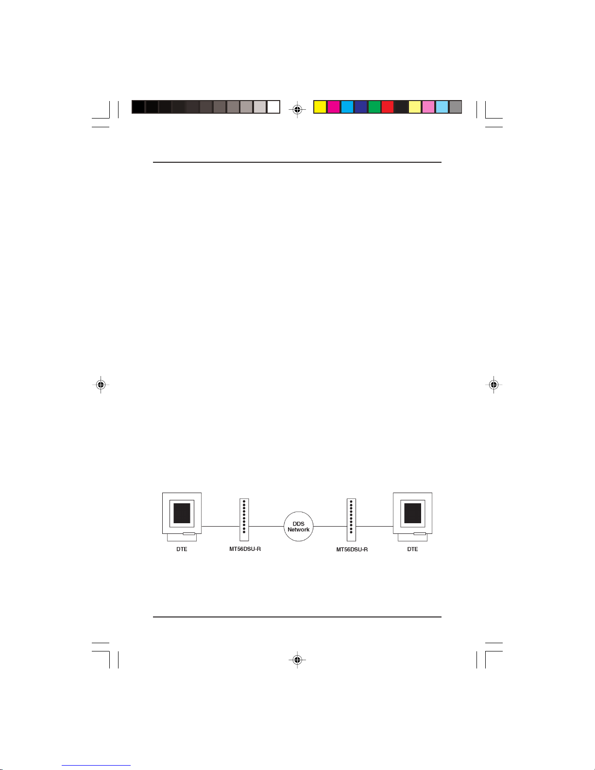
The figure below shows the MT56DSU-R in a basic DDS network
installation.
Basic DSU/CSU Configuration
8
82023101.p65 2/12/01, 2:52 PM8
Figure 1-1.

Chapter 1 - Introduction and Description
1.5 Features
The MT56DSU-R provides many useful features. Standard features
include V.35 and RS232 connections and either synchronous and
asynchronous transmission; synchronous at rates up to 56000 bps
and asynchronous up to 19200 bps; selectable digital data rates
that match the services offered by the carriers. Other features
include user-selectable clocking options, elastic store for analog offnet extensions, anti-streaming, and RTS and DSR signal forced-on
selection.
Your Multi-Tech DSU/CSU provides the following features:
supports direct connection to the DATAPHONE® Digital Data
Service (DDS) or compatible network
selectable sync speeds of 2400, 4800, 9600, 19200 and 56000
bps
selectable async speeds of 2400, 4800, 9600, and 19200 bps
point-to-point and multipoint operation
Standard RS232C, V.35 and DDS interfaces provided
anti-streaming (for multi-point operations)
elastic store (for analog off-net extensions)
system status
circuit assurance
multiple selectable clocking
* External clocking
* Internal clocking
* DDS (slave) clocking
RTS signal forced on selection
DSR signal forced on selection
multiple MT56DSU-R activated diagnostic tests:
* Local loopback test
* Digital loopback test
* Test pattern generator/detector
multiple telco-activated diagnostic tests:
* DSU loopback test
* CSU loopback test
82023101.p65 2/12/01, 2:52 PM9
9

MT56DSU-R Owner's Manual
1.6 FCC Regulations for Telephone Line
Interconnection
1. This equipment complies with Part 68 of the FCC rules. On the
outside surface of the rack is a label that contains, among other
information, the FCC registration number and ringer
equivalence number (REN). If requested, this information must
be provided to the telephone company.
2. As indicated in Appendix B, the suitable jack (USOC)
connection arrangement for this equipment is shown. If
applicable, the facility interface codes (FIC) and service order
codes (SOC) are shown.
3. The ringer equivalence number (REN) is used to determine the
quantity of devices which may be connected to the telephone
line. Excessive REN's on the telephone line may result in the
devices not ringing in response to an incoming call. In most, but
not all areas, the sum of the REN's should not exceed five (5.0).
To be certain of the number of devices that may be connected
to the line, as determined by the total REN's, contact the
telephone company to determine the maximum REN for the
calling area.
4. If this equipment causes harm to the telephone network, the
telephone company will notify you in advance. But if advance
notice isn't practical, the telephone company will notify the
customer as soon as possible. Also, you will be advised of your
right to file a complaint with the FCC if you believe it is
necessary.
5. The telephone company may make changes in its facilities,
equipment, operation, or procedures that could affect the
operation of the equipment. If this happens, the telephone
company will provide advance notice in order for you to make
necessary modification in order to maintain uninterrupted
service.
6. If trouble is experienced with this equipment (the model of
which is indicated below) please contact Multi-Tech Systems,
Inc. at the address shown below for details of how to have
repairs made. If the trouble is causing harm to the telephone
network, the telephone company may request you remove the
equipment from the network until the problem is resolved.
10
82023101.p65 2/12/01, 2:52 PM10

Chapter 1 - Introduction and Description
7. No repairs are to be made by you. Repairs are to be made only
by Multi-Tech Systems or its licensees. Unauthorized repairs
void registration and warranty.
8. This equipment cannot be connected to public coin service
provided by the telephone company. (Contact the state public
utility commission, public service commission or corporation
commission for information.)
Manufacture: Multi-Tech Systems, Inc.
Model number: MT56DSU-R
FCC Registration No.: AU7USA-18883-DE-N
Ringer Equivalence: N/A
Modular Jack (USOC) RJ48S
Service Center in U.S.A.: Multi-Tech Systems, Inc.
2205 Woodale Drive
Mounds View, MN 55112
(612) 785-3500 or
(800) 328-9717
U.S. Fax (612) 785-9874
82023101.p65 2/12/01, 2:52 PM11
11

MT56DSU-R Owner's Manual
1.7 Specifications
Model Number MT56DSU-R
Device Operation combined DSU and CSU
Data Rates
Synchronous 2400, 4800, 9600, 19200, 56000 bps
Asynchronous 2400, 4800, 9600, 19200 bps
Interfaces RS232C, V.35, DDS
Temperature 0 to 50o C
Humidity 95% (non-condensing)
Dimensions 0.75" H x 5.5" W x 10.4" D
1.8 cm H x 13.5 cm W x 26 cm D
Weight 0.6 Lbs. (0.3 Kg.)
CertificationFCC Part 15 Class A
FCC Part 68
UL Listed
Compatibility AT&T Pubs 62310 and 41450
FIC Codes 04DU5-24 2.4 Kbps digital interface
04DU5-48 4.8 Kbps digital interface
04DU5-96 9.6 Kbps digital interface
04DU5-19 19.2 Kbps digital interface
04DU5-56 56 Kbps digital interface
USOC Jack RJ48S
Transmitter/Receiver
Modulation bipolar return to zero
Transmit Level 1.4V peak (+6dBm) into 135 Ohm at 2400,
4800,19200, and 56000 bps
0.7V peak (0 dBm) into 135 ohm at 9600
bps
Output Impedance 135 ohms
Receive Levels +6 to -40 dbm at 2400 bps
+6 to -40 dBm at 4800 bps
0 to -40 dBm at 9600 bps
+6 to -40 dBm at 19200 bps
+6 to -45 dBm at 56000 bps
12
82023101.p65 2/12/01, 2:52 PM12

Chapter 1 - Introduction and Description
Input Impedance 135 ohms
Delay Times (in msecs.)
RTS/CTS DCD on DCD off
2400 8.1 7.5 7.0
4800 4.3 2.6 3.5
9600 2.2 1.6 1.5
19200 1 0.8 0.7
56000 0.4 0.3 0.2
82023101.p65 2/12/01, 2:52 PM13
13

MT56DSU-R Owner's Manual
14
82023101.p65 2/12/01, 2:52 PM14
TM
MultiDSU56K
Chapter 2 -Hardware Installation
82023101.p65 2/12/01, 2:52 PM15
MT56DSU-R Owner's Manual
2.1 Introduction
This chapter provides the information needed to configure and
install the MT56DSU-R in a Multi-Tech Systems CC216G modem
rack. This manual assumes the reader is familiar with the function
and operation of data communications equipment and is technically
qualified to provide installation service.
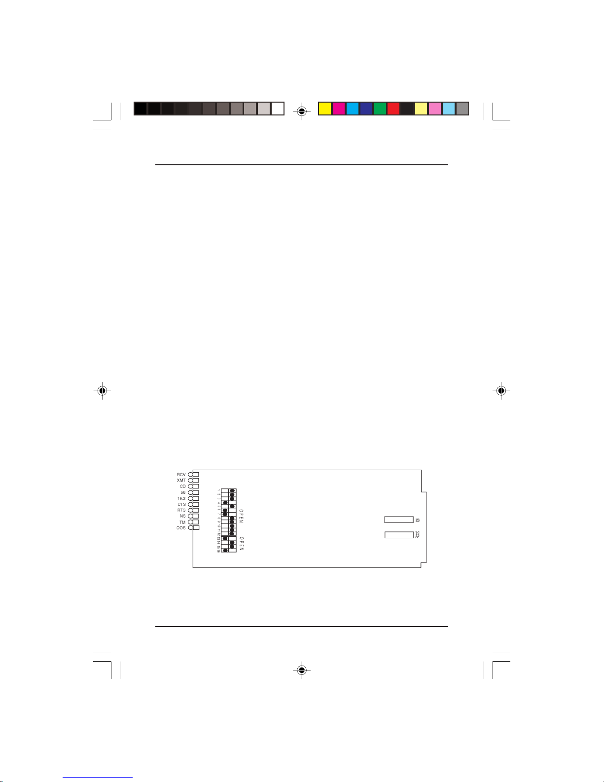
2. 2 Default DIP Switch and Jumper Settings
The MT56DSU-R printed circuit board contains a 12-position DIP
switch block which is labeled 1 through 12 and a 4-position DIP
switch block which is labled 13 through 16 as shown in Figure 2-1.
They are located behind the LEDs on the front of the board. Each
individual switch is numbered and can be in either the up (OPEN) or
down (CLOSED) position.
The MT56DSU-R is shipped from the factory with the configuration
DIP switches set to the most common settings.
The factory-set (default) settings are: 56K Data Rate, DDS Clocking,
RTS Forced On, DSR Forced On, Sync Mode, Loopback Test
Disabled, Test Pattern Disabled, Circuit Assurance Disabled, System
Status Disabled, 10-Bit Async Word Length, Elastic Store Disabled,
and Anti-Streaming Disabled. If you need to change any of these
settings, refer to the Changing Defaults sections below.
The MT56DSU-R switches are shown below.
MT56DSU-R Board Layout
16
82023101.p65 2/12/01, 2:52 PM16
Figure 2-1.

Chapter 2 - Hardware Installation
2.2.1 12 -Position DIP Switch (# 1-12)
The 12-position DIP switch is used to set data rate, clocking, RTS
control, DSR control, and Async/Sync operation, diagnostic modes
(Loopback Test, Test Pattern ), Circuit Assurance, and System
Status. The default settings are shown in Table 2-1. If you want to
make changes to one of these settings, refer to section 2.3.
2.2.2 4-Position DIP Switch (# 13-16)
The 4-position DIP switch is used to select Async Word Length,
Elastic Store, and Anti-Streaming options. The defaults are 10-Bit
Async Word Length, Elastic Store disabled, and Anti-Streaming
disabled. If changes to these settings are required, refer to section
2.3.
2.2.3 RS232/V.35 Shunt
Data terminal equipment with either a RS232 or V.35 interface can
be connected to the DB25 connector on the backplane of the rack.
The 16-pin shunt on the back of the MT56DSU-R board must be
placed in either the "V.35 position or the "RS232" position. The
interface is determined by the position of this 16-pin shunt. The
MT56DSU-R is shipped from the factory with the 16-pin shunt in the
RS232 position.
82023101.p65 2/12/01, 2:52 PM17
17

MT56DSU-R Owner's Manual
2.3 Changing the Default DIP Switch Settings
Use Table 2-1 to determine the DIP switch setting changes required
for your MT56DSU-R to operate in your particular environment.
You may want to record your switch setting changes for future
reference (e.g., troubleshooting, equipment moves/changes, calling
Tech Support). The DIP switches are illustrated in Figure 2-1.
The factory default settings are indicated by an * in the Table 2-1.
Table 2-1. MT56DSU-R Switch Settings
Switch Description
Data Rate (in bps)
2400 4800 9600 19.2K 56K (*)
-1 Down Down Down Down Up *
-2 Down Up Down Up Up *
-3 Down Down Up Up Up *
Clocking
Internal External DDS (*)
-4 Up Down Down *
-5 Up Down Up *
-6 Up - RTS controlled by DTE
Down - RTS forced On *
-7 Up - DSR depends on the status of the link
Down - DSR forced on *
-8 Up - Synchronous operation *
Down - Asynchronous operation
18
82023101.p65 2/12/01, 2:52 PM18
RTS Control
DSR Control
Async/Sync Operation

Chapter 2 - Hardware Installation
Table 2-1. MT56DSU-R Switch Settings (Cont'd)
Switch Description
Normal/Diagnostics Mode
-9 Up - normal operating mode *
Down - Loopback Test enabled
-10 Up - normal operating mode *
Down - Test Pattern enabled
Link Status Options
-11 Up - Circuit Assurance disabled *
Down - Circuit Assurance enabled
-12 Up - System Status disabled *
Down - System Status enabled
Async Word Length
9-Bit 10-Bit* 11-Bit
-13 Up Down * Up
-14 Down Up * Up
Elastic Store
-15 Up - Elastic Store disabled *
Down - Elastic Store enabled
-16 Up - Anti-Streaming enabled
Down - Anti-Streaming disabled *
* Factory default selection
82023101.p65 2/12/01, 2:52 PM19
Anti-Streaming
19

MT56DSU-R Owner's Manual
2.4 Installation Procedure
After your CC216G modem rack has been installed in your computer
cabinet or in a stand-alone cabinet of your choosing, the MT56DSUR can be inserted into the rack. Refer to the Rack Mounted Modems
Owner's Manual for rack installation procedures. Then, perform the
following procedure in Table 2-2 to install the MT56DSU-R.
Table 2-2. Installation
1. Verify that the DIP switches on the MT56DSU-R are set for your
particular configuration; refer to Table 2-1.
2. Before the MT56DSU-R is inserted into the modem rack, the
16-pin shunt on the back of the board needs to be in correct
position. If the MT56DSU-R is being connected to a RS232
interface, the 16-pin shunt needs to be placed in the "RS-232"
position. If the MT56DSU-R is being connected to a V.35
interface, place the 16-pin shunt in the "V.35" position.
3. Determine which slot the MT56DSU-R board is going to be
placed in the rack. Apply the DSU LED sticker to the door, refer
to the Rack Mounted Modems Owner's Manual for the notes
about the CC216G.
4. Open the door of the modem rack.
5. Ensure that the MT56DSU-R board is positioned so that the
LEDs are toward the top of the board, insert the board in the
slot you have choosen to add the DSU LED sticker. The board's
gold edge connector will mate with the rack's backplane. The
edge connector is offset so that the board cannot be inserted
incorrectly.
6. To connect the DTE to the MT56DSU-R using an RS232 cable,
connect the cable to the RS232 port on the DTE and the other
end to the DB25 connector on the back of the rack. Refer to the
Rack Mounted Modems Owner's manual for cable connections.
20
82023101.p65 2/12/01, 2:52 PM20
 Loading...