

Multi-Tech MT5656RJ-L-92, MT5656RJ, MT5656RJ-92, MT5656RJ-L-34, MT5656RJ-L-32 Developer's Manual
...Page 1

RJModem
MT5656RJ
Developer's Guide
Page 2

Copyright and Technical Support
RJModem™ Developer's Guide
MT5656RJ
PN S000363I, Version I
Copyright
This publication may not be reproduced, in whole or in part, without prior expressed written permission from MultiTech Systems, Inc. All rights reserved.
Copyright © 2004-6 by Multi-Tech Systems, Inc.
Multi-Tech Systems, Inc. makes no representations or warranties with respect to the contents hereof and specifically
disclaim any implied warranties of merchantability or fitness for any particular purpose. Furthermore, Multi-Tech
Systems, Inc. reserves the right to revise this publication and to make changes from time to time in the content hereof
without obligation of Multi-Tech Systems, Inc. to notify any person or organization of such revisions or changes.
Revisions
Revision Level Date Description
A 09/24/04 Initial release.
B 10/05/04 Added one drawing (bottom view) to the Dimensions page.
C 10/14/04 Changed the RJModem drawing on page 10. Changed 5 V Serial Electrical to
VDDMAX=5.5 V. In the same table, removed the Current Drive cell.
D 05/12/05 Added the EMI filtering diagram. Updated the PCB footprint. Added panel-mounting
kit and board-mounting diagrams.
E 06/30/05 Added one more panel-mounting diagram. Add information on Transmit Clock
(TXCLK) and Receive Clock (RXCLK). Added reference to the separate AT
Command document for RJModem. Added Waste Electrical and Electronic
Equipment (WEEE) Notice.
F 07/08/05 Changed the Waste Electrical & Electronic Equipment (WEEE) Statement to Rev. B.
G 07/12/05 Added more text to the Pin Descriptions drawings.
H 11/30/05 Changed panel-mounting diagrams. Changed board drawing.
I 12/22/06 Changed the pin drawing. Changed the order of the drawings on pages 6 to 9.
RXCLK is now labeled output. Reversed the columns of pin numbers on the
schematic on page 17. Updated the following specifications: Certifications, DAA
isolation, power requirements.
Trademarks
Trademarks and registered trademarks of Multi-Tech Systems, Inc. are RJModem and the Multi-Tech logo.
Microsoft and Windows are registered trademarks or trademarks of Microsoft Corporation in the United States and/or
other countries.
Patents
This device covered by one or more of the following patents: 6,031,867; 6,012,113; 6,009,082; 5,905,794; 5,864,560;
5,815,567; 5,815,503; 5,812,534; 5,809,068; 5,790,532; 5,764,628; 5,764,627; 5,754,589; 5,724,356; 5,673,268;
5,673,257; 5,644,594; 5,628,030; 5,619,508; 5,617,423; 5,600,649; 5,592,586; 5,577,041; 5,574,725; 5,559,793;
5,546,448; 5,546,395; 5,535,204; 5,500,859; 5,471,470; 5,463,616; 5,453,986; 5,452,289; 5,450,425; 5,355,365;
5,309,562; 5,301,274; 7,082,106; 7,082,141; 7,092,406. Other Patents Pending.
World Headquarters
Multi-Tech Systems, Inc.
2205 Woodale Drive
Mounds View, Minnesota 55112
Phone: 763-785-3500 or 800-328-9717
Fax: 763-785-9874
Technical Support
Country By Email By Phone
France: support@multitech.fr +(33) 1-64 61 09 81
India: support@multitechindia.com +91 (124) 2340780
Europe, Asia, Africa: support@multitech.co.uk +(44) 118 959 7774
U.S., Canada, all others: support@multitech.com (800) 972-2439 or (763) 717-5863
Internet Address: http://www.multitech.com
Multi-Tech Systems, Inc. RJModem Developer's Guide (S000363I) 2
Page 3

Table of Contents
Table of Contents
Chapter 1 – RJModem Hardware................................................................................................................................4
Introduction .............................................................................................................................................................4
RJModem Features ................................................................................................................................................4
Product Ordering Information.................................................................................................................................. 4
Developer Kit ..........................................................................................................................................................4
AT Commands ........................................................................................................................................................ 4
Technical Specifications .........................................................................................................................................5
Dimensions .............................................................................................................................................................6
For Board Mounting.........................................................................................................................................6
Panel Mounting .......................................................................................................................................................7
Attaching the Mounting Bracket ..............................................................................................................................7
Dimensional Drawing of the Bracket ....................................................................................................................... 8
Cable Specifications ...............................................................................................................................................8
PCB Footprint .........................................................................................................................................................9
Pinout Dimensions ................................................................................................................................................ 10
Pin Descriptions .................................................................................................................................................... 10
Transmit Clock (TXCLK) and Receive Clock (RXCLK)..................................................................................11
&Q – Sync/Async Mode.................................................................................................................................11
&W – Store Current Configuration .................................................................................................................11
Electrical Characteristics....................................................................................................................................... 12
3.3 V Serial RJModem...................................................................................................................................12
5 V Serial RJModem......................................................................................................................................12
Handling Precautions.....................................................................................................................................12
RJModem Developer Board.................................................................................................................................. 13
5 V / 3.3 V Jumper – JP6...............................................................................................................................14
RJModem Schematics...................................................................................................................................15
Design Considerations..........................................................................................................................................19
PC Board Layout Guidelines..........................................................................................................................19
Electromagnetic Interference (EMI) Considerations ......................................................................................19
EMI Filtering...................................................................................................................................................20
Chapter 2 – Telecom Approvals and Regulatory Information................................................................................21
Telecom Approvals ...............................................................................................................................................21
Regulatory Compliance Statements......................................................................................................................22
EMC, Safety, and R&TTE Directive Compliance...........................................................................................22
International Modem Restrictions ..................................................................................................................22
Telecom Requirements for the United States................................................................................................22
Industry Canada ............................................................................................................................................22
New Zealand Telecom Warning Notice..........................................................................................................23
South African Statement................................................................................................................................23
Other..............................................................................................................................................................23
Chapter 3 – Multi-Tech Warranty and Repairs Policy.............................................................................................24
Multi-Tech Warranty Statement ............................................................................................................................24
Repair Procedures for U.S. and Canadian Customers ..................................................................................24
Repair Procedures for International Customers (Outside U.S.A. and Canada) .............................................25
Repair Procedures for International Distributors............................................................................................25
Chapter 4 – Waste Electrical and Electronic Equipment (WEEE) Statement........................................................26
Index............................................................................................................................................................................27
Multi-Tech Systems, Inc. RJModem Developer's Guide (S000363I) 3
Page 4
Chapter 1 – RJModem Hardware
Chapter 1 – RJModem Hardware
Introduction
The Multi-Tech RJModem creates communication-ready devices by integrating modem functionality into the most
compact, integrated device. The first-of-its-kind RJ11 form factor includes the controller, data pump, and DAA
providing device manufacturers with the ability to integrate dial-up connectivity into any product design. With minimal
engineering effort, the RJModem instantly adds global communication capabilities, enhancing the end user
experience and increasing product value.
RJModem Features
• Complete data modem including the controller, data pump, DAA, and RJ-11 connector
• V.92/56K, V.34/33.6K, V.32vis/14.4K data rate options
• High speed models backward compatible with lower speeds
• Telecom approved in more than 50 countries (some pending)
• V.44 and V.42 bis data compression
• V.42 error correction
• Intelligent DAA technology detects line status
• AT command compatible
• U. S. Caller ID reporting
• Low power/sleep mode
• FastPOS (V.29) and V.22vis Fast Connect
• V.80 Synchronous Access
• 3.3V or 5V power input options
• Board mount or remote panel mounting
• Two-year warranty
Product Ordering Information
Product Description Region
MT5656RJ-92 V.92 Serial Data Only 5V Global
MT5656RJ-34 V.34 Serial Data Only 5V Global
MT5656RJ-32 V.32bis Serial Data Only 5V Global
MT5656RJ-L-92 V.92bis Serial Data Only 3.3V Global
MT5656RJ-L-34 V.34 Serial Data Only 3.3V Global
MT5656RJ-L-32 V.32bis Serial Data Only 3.3V Global
MTRJ-DK Developer Kit Global
MTRJ-RMK Panel Mounting Kit for RJModem Global
Ordering Codes Description
92 V.92/56K Data Rate
34 V.34/33.6K Data Rate
32 V.32bis/14.4K Data Rate
L 3.3V Power Input
Note: Lead-free builds of the RJModem are available. Contact your sales representative.
Order this Product
3
Developer Kit
A Developer Kit is available. This kit provides the ability to plug in the RJModem and use it for testing, programming,
and evaluation. The kit includes one developer board with RS-232 DB-25 connector, universal power supply, RS-232
cable, RJ-11 cable, MTRJ-RMK Panel Mounting Kit, and Developer Guide CD.
AT Commands
The AT Commands for the RJModem are published in a separate document (document number S000364x) available
on the Developer Guide CD and on the Multi-Tech Web site.
Multi-Tech Systems, Inc. RJModem Developer's Guide (S000363I) 4
Page 5
Chapter 1 – RJModem Hardware
Technical Specifications
The RJModem meets the following specifications:
Category Description
Data Standards
Data Format
Serial Speeds
Client-to-Server Data Rates
Client-to-Client Data Rates
Error Correction
Data Compression
Modes of Operation
Dimensions
Weight
Operating Temperature 3.3 V and 5V Build Options
Storage Temperature
Humidity
Operating Voltage 5V DC Build Option ± 10% – Absolute Maximum Supply Voltage: 5.5VDC
Power Requirements 5V Build Option Typical: 93mA (.46W @ 5VDC)
Transmit Level
Receiver Sensitivity
Frequency Stability
DAA Isolation
Flow Control
Command Buffer
Telephony / TAM
Certifications and
Approvals
Warranty
Intelligent Features
V.92/V.90/56K, V.34/33.6K, V.32bis/14.4K, V.22, V.23, V.21;
Bell 212A and Bell103
Serial, binary, asynchronous
Serial port data rates adjustable to 300, 1200, 2400, 4800, 9600, 19,200,
38,400, 57,600, 115,200
Supports V.92 and V.90 data rates
33,600; 31,200; 28,800; 26,400; 24,000; 21,600; 19,200; 16,800; 14,400;
12,000; 9600; 7200; 4800; 2400; 1200; 0-300 bps
Data Mode: V.42 (LAPM or MNP 2–4)
V.44, V.42bis and MNP Class 5
Full duplex over dial-up lines; data mode, command mode, and online command
mode, V.54 test mode
.709" w x 2.519" h x .752 d (1.8 cm x 6.4 cm x 1.92 cm)
64 oz. (0.02 Kg)
0 to +50° C ambient under closed conditions
-40 to +85° C
Humidity range 20% to 90% (non-condensing)
3.3V DC Build Option ± 10% – Absolute Maximum Supply Voltage: 3.6VDC
Maximum: 112mA (.59W @ 5.25VDC)
3.3 V Build Option Typical: 100mA (.33W @ 3.3VDC)
Maximum:112mA (.40W @ 3.6VDC)
-11 dBm (varies by country setting)
-43 dBm under worst-case conditions
±0.01%
1.5Kv r.m.s. or 2121 VDC at working voltage of 250VAC
XON/XOFF (software), RTS/CTS (hardware)
60 characters
TAM (Telephone Answering Machine): S-101 AT+V commands (no CODEC for
speakers/microphone interface)
Safety Certifications EMC Approvals
UL 60950-1 FCC Part 15 (Class B)
IEC 60950-1 Canada (Class B)
AS/NZS 6950:2000 EN 55022 (Class B)
CCC EN 55024
Two years
Complete data modem including the controller, data pump, DAA, and RJ-11
connector
High speed models backward compatible with lower speeds
Telecom approved in more than 50 countries (some pending)
Intelligent DAA technology detects line status
AT command compatible
U. S. Caller ID reporting
Low power/sleep mode
FastPOS (V.29) and V.22vis Fast Connect
V.80 Synchronous Access
Board mount or remote panel mounting
Multi-Tech Systems, Inc. RJModem Developer's Guide (S000363I) 5
Page 6
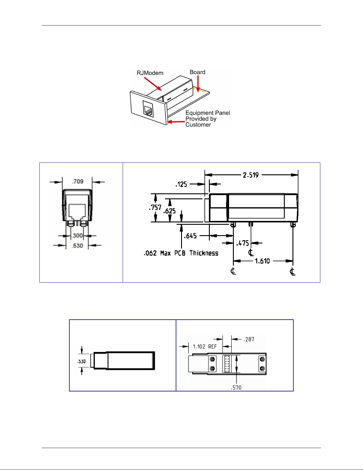
Dimensions
For Board Mounting
Chapter 1 – RJModem Hardware
Top View
Bottom View
Multi-Tech Systems, Inc. RJModem Developer's Guide (S000363I) 6
Page 7
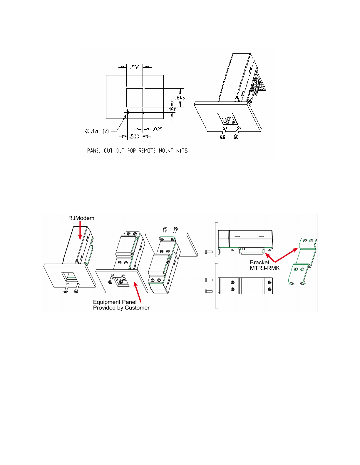
Panel Mounting
Note: Screws, bracket and ribbon cable are included in the panel-mounting kit.
Chapter 1 – RJModem Hardware
Attaching the Mounting Bracket
Multi-Tech Systems, Inc. RJModem Developer's Guide (S000363I) 7
Page 8
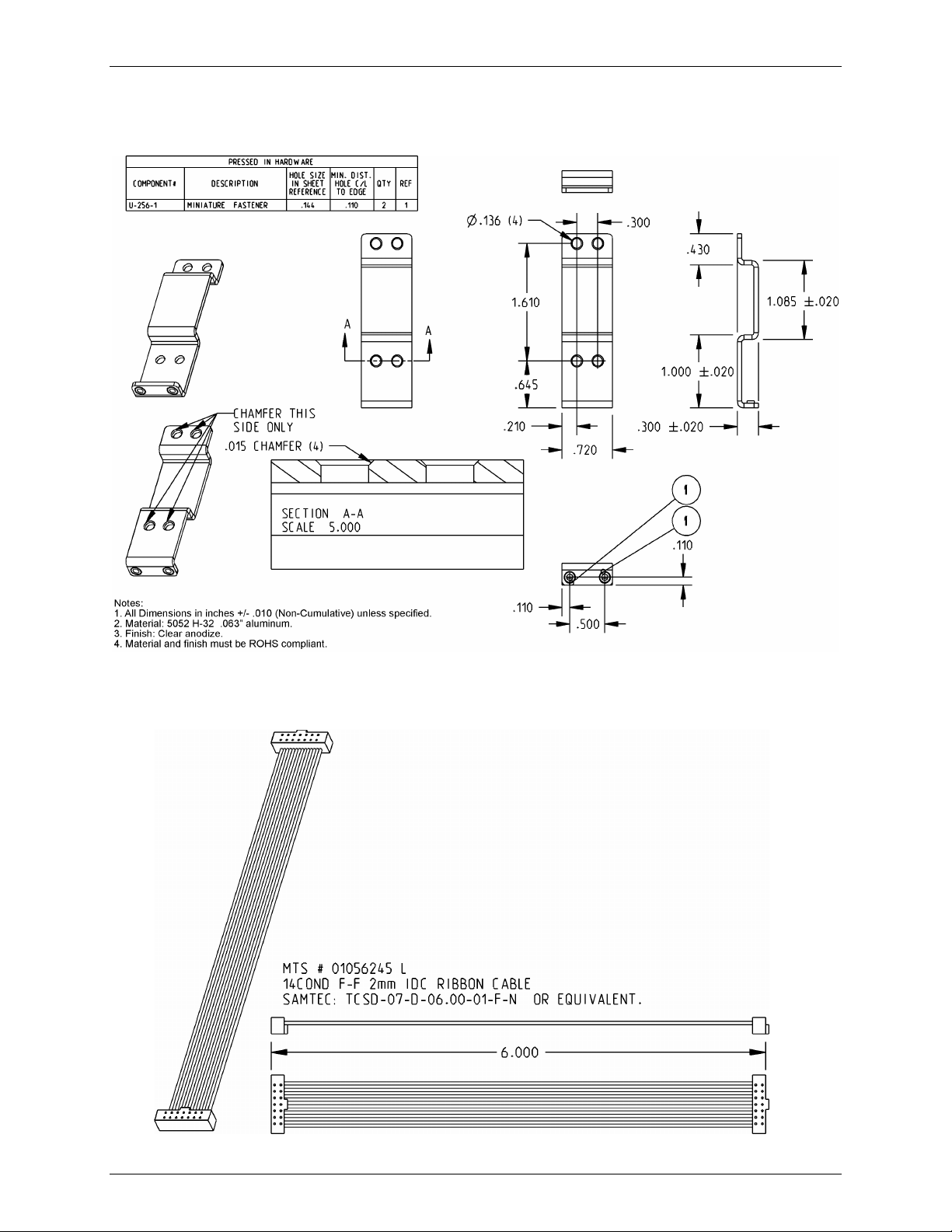
Chapter 1 – RJModem Hardware
Dimensional Drawing of the Bracket
Cable Specifications
Multi-Tech Systems, Inc. RJModem Developer's Guide (S000363I) 8
Page 9
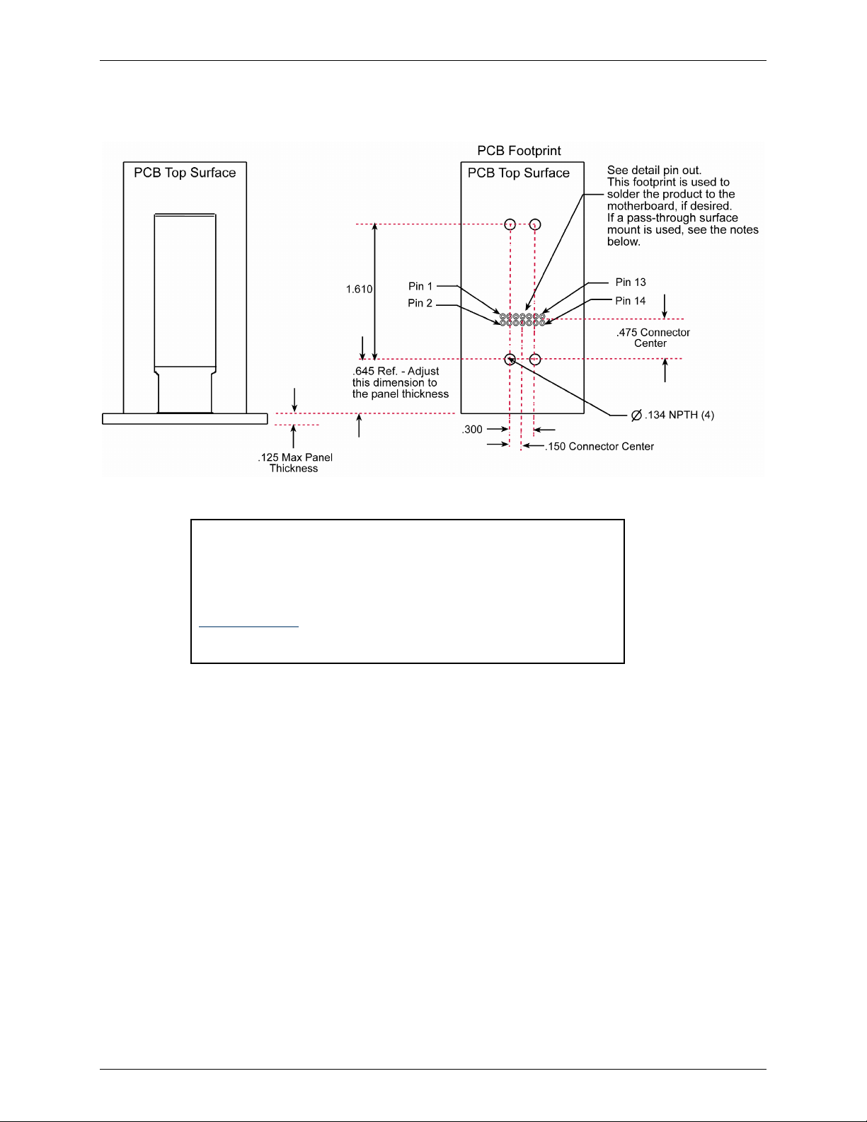
PCB Footprint
Chapter 1 – RJModem Hardware
Notes:
Surface mount connectors are approved in place of soldering the unit to
the motherboard.
Follow the "Pass Through" footprint instructions on the part data sheets.
The following are recommended by Multi-Tech:
www.samtec.com
SAMTEC: SMM-107-02-S-D-(other option) or equivalent
SAMTEC: CLT-107-02-(plating option)-D-(other option) or equivalent
Multi-Tech Systems, Inc. RJModem Developer's Guide (S000363I) 9
Page 10

Pinout Dimensions
PCB Footprint or Board Lay-out (Note: This is the PCB top view)
Pin Descriptions
Top View
PCB Top Surface
Chapter 1 – RJModem Hardware
Front RJModem Jack Opening
Signal
Pin
Name
1
–RI O RING (Active Low). Incoming ring signal from phone.
2
–DCD O Data Carrier Detect (Active Low). –DCD output is ON (low) when a data connection is
3
–DTR I Data Terminal Ready (Active Low). The –DTR input is turned ON (low) when the DTE is
4
–RESET I Device Reset (with pull-up). The active low –RESET input resets the device logic and
5
VCC PWR
6
–CTS O Clear to Send (Active Low). –CTS is controlled by the module to indicate whether or not
7
–RTS I Request to Sent (Active Low). –RTS signal is used for hardware flow control. –RTS
IN/OUT
Type
Description
Ring Indicate. –RI output ON (low) indicates the presence of an ON segment of a ring
signal on the telephone line. The modem will not go off-hook when –RI is active; the
modem waits for –RI to go inactive before going off-hook.
established and the module is ready to send/receive data.
ready to communicate. –DTR ON prepares the modem to be connected, and, once
connected, maintains the connection. –DTR OFF places the modem in the disconnect
state under control of the &Dn and &Qn commands.
returns the configuration of the device to the original factory default values or "stored
values" in the NVRAM. –RESET is tied to VCC through a time-constant circuit for “Poweron-Reset” functionality. The module is ready to accept commands after a fixed amount of
time after power-on or reset.
DC Input Power. 3.3 V or 5 V DC power, depending upon the build.
the module is ready to transmit data. –CTS ON indicates to the DTE that signals on TXD
will be transmitted. –CTS OFF indicates to the DTE that it should not transfer data on TXD.
input ON (low) indicates that the DTE is ready to send data to the modem. In the
command state, the modem ignores –RTS.
Multi-Tech Systems, Inc. RJModem Developer's Guide (S000363I) 10
Page 11

Chapter 1 – RJModem Hardware
Signal
Pin
Name
8
TXCLK O Transmit Data Sync Clock. TX synchronous data clock for sync data mode. More
IN/OUT
Type
Description
information below.
9
–TXD I Transmitted Data. The DTE uses the –TXD line to send data to the module for
transmission or to transmit commands to the module. The DTE should hold this circuit in
the mark state when no data is being transmitted or during intervals between characters.
10
–RXD O Received Data. The module uses the RXD line to send data to the DTE and to send
module responses to the DTE. In command mode, –RXD data presents the module
responses to the DTE. Module responses take priority over incoming data when the two
signals are in competition for –RXD. When no data is transmitted, the signal is held in
mark condition.
11
CLK Optional 28.224 or 27 mhz clk input (requires special build option)
12
GND GND
13
SPKR Speaker. Call Progress signaling on MT5656RJ is a square wave output that can be
Logic Ground.
optionally connected to a low-cost single-ended speaker; e.g., a sounducer or an analog
speaker circuit.
14
RXCLK O Receive Data Sync Clock. RX synchronous data clock for sync data mode. More
information below.
Transmit Clock (TXCLK) and Receive Clock (RXCLK)
Transmit Clock (TXCLK) and Receive Clock (RXCLK) pins are used in synchronous (sync) mode serial
communication. They are needed when using a synchronous terminal device to keep synchronization between the
modem and the terminal device on the serial port. Transmit Clock (TXCLK) and Receive Clock (RXCLK) are not used
in asynchronous mode.
However, most applications use asynchronous mode because synchronous ports are not as common as
asynchronous ports on computer hardware. For asynchronous operation the host system does not need to
connect to the TXCLK and the RXCLK pins on the RJModem; you can use a 9-pin interface.
Synchronous mode can be set with the &M command and stored with the &W command. See the RJModem AT
command guide available on the RJModem Developer Kit CD and the Multi-Tech Web site.
&Q – Sync/Async Mode
Description: This command is an extension of the &M command and is used to control the connection modes permitted. It is
Syntax: &Q<value>
Defined Values: <value> Decimal number corresponding to the selected option.
0 – Selects direct asynchronous operation. The value 000b is written to S27 bits 3, 1, and 0, respectively.
1 – Selects synchronous connect mode with async off-line command mode. The value 001b is written to
2 – Selects synchronous connect mode with async off-line command mode and enables DTR dialing of
3 – Selects synchronous connect mode with async off-line command mode and enables DTR to act as
5 – The modem will try to negotiate an error-corrected link. The modem can be configured using S36 to
6 – Selects asynchronous operation in normal mode (speed buffering). The value 110b is written to S27 bits
Result Codes: OK <value> = 0 to 3, 5, or 6
ERROR
&W – Store Current Configuration
Description: Saves the current (active) configuration (profile), including S-Parameters, in one of the two user profiles in
The current configuration is comprised of a list of storable parameters illustrated in the &V command. These
Syntax: &W<value>
Defined Values: <value> Decimal number corresponding to the selected profile.
0 – Store the current configuration as profile 0.
1 – Store the current configuration as profile 1.
Result Codes: OK <value> = 0 or 1.
ERROR Otherwise.
used in conjunction with S36 and S48. Note: When &Q0 to &Q3 are issued to select the mode, the subsequent
connect message will report the DCE speed regardless of the W command and S95 settings.
See &M0.
S27 bits 3, 1, and 0, respectively. See &M1. (Serial interface operation only.)
directory 0. The value 010b is written to S27 bits 3, 1, and 0, respectively. See &M2. (Serial interface
operation only.)
Talk/Data switch. The value 011b is written to S27 bits 3, 1, and 0, respectively. See &M3. (Serial
interface operation only.)
determine whether a failure will result in the modem returning on-hook or will result in fallback to an
asynchronous connection. The value 101b is written to S27 bits 3, 1, and 0, respectively. (Default.)
3, 1, and 0, respectively.
NVRAM as denoted by the parameter value. This command will yield an ERROR message if the NVRAM is not
installed or is not operational as detected by the NVRAM test.
settings are restored to the active configuration upon receiving a Zn command or at power up (see &Yn).
Multi-Tech Systems, Inc. RJModem Developer's Guide (S000363I) 11
Page 12

Electrical Characteristics
3.3 V Serial RJModem
3.3 V DC Characteristics (TA = 0°C to 70°C; VDD = 3.3 V ± 0.3 V) VDDMAX = 3.6 V
Inputs
–DTR (3), –TXD (9), –RTS (7), –RESET (3), XCLK (11),
PWR (5), GND (12)
Outputs
–DCD (2), –CTS (6), –RI (1), –RXD (10), RDCLK (14), TDCLK (8)
2 mA, Z INT = 120 Ω
Digital Input Capacitance
5 V Serial RJModem
5 V DC Characteristics (TA = 0 °C to 50 °C; VDD = 5 V ± 0.25 V) VDDMAX = 5.5 V
Inputs
–DTR (3), –TXD (9), –RTS (7), –RESET (3), XCLK (11), PWR (5),
GND (12)
Outputs
–DCD (2), –CTS (6), –RI (1), –RXD (10), RDCLK (14), TDCLK (8),
SPKR (13)
2 mA, Z INT = 120 Ω
Digital Input Capacitance
Chapter 1 – RJModem Hardware
Input High
Min 2.0 V
Output High
Min 2.4 V
Input High
Min 2 V
Output High
Min 2.4 V
Input Low
Max 0.8 V
Output Low
Max 0.5 V
Input Low
Max 0.8 V
Output Low
Max 0.5 V
20pF
20 PF
Handling Precautions
All electronic devices should be handled with certain precautions to avoid damage due to the accumulation of
static charge. Although input protection circuitry has been incorporated into the devices to minimize the effect of
this static buildup, proper precautions should be taken to avoid exposure to electrostatic discharge during
handling and mounting.
Multi-Tech Systems, Inc. RJModem Developer's Guide (S000363I) 12
Page 13

RJModem Developer Board
Chapter 1 – RJModem Hardware
Multi-Tech Systems, Inc. RJModem Developer's Guide (S000363I) 13
Page 14

Chapter 1 – RJModem Hardware
5 V / 3.3 V Jumper – JP6
The operating voltage factory default setting is 3.3 V. The JP1 jumper must be set to 3.3-volt.
Warning – Be sure to that 5 V/3.3 V jumper is set to match the requirements of your RJModem.
If this jumper is set incorrectly, damage to the RJModem and/or the Test/Demo card could result.
Caution – Use only the provided Multi-Tech Systems, Inc. transformer with the Test/Demo board. Use of any
other power source will void the warranty and will likely damage the Test/Demo board and the RJModem. The
transformer connector is keyed to prevent improper connection to the Test/Demo board.
Multi-Tech Systems, Inc. RJModem Developer's Guide (S000363I) 14
Page 15

RJModem Schematics
Chapter 1 – RJModem Hardware
Multi-Tech Systems, Inc. RJModem Developer's Guide (S000363I) 15
Page 16

Chapter 1 – RJModem Hardware
To view the text and numbers, increase the viewing percentage to 150% or print the page.
Multi-Tech Systems, Inc. RJModem Developer's Guide (S000363I) 16
Page 17

Chapter 1 – RJModem Hardware
Multi-Tech Systems, Inc. RJModem Developer's Guide (S000363I) 17
Page 18

To view the text and numbers, increase the viewing percentage to 150% or print the page.
Chapter 1 – RJModem Hardware
Multi-Tech Systems, Inc. RJModem Developer's Guide (S000363I) 18
Page 19

Chapter 1 – RJModem Hardware
Design Considerations
Good engineering practices must be adhered to when designing a printed circuit board (PCB) containing the
RJModem. Suppression of noise is essential to the proper operation and performance of the modem itself and for
surrounding equipment.
Two aspects of noise in an OEM board design containing the RJ Modem must be considered: on-board/off-board
generated noise that can affect digital signal processing. Both on-board and off-board generated noise that is coupled
on-board can affect interface signal levels and quality. Of particular concern is noise in frequency ranges affecting
modem performance.
On-board generated electromagnetic interference (EMI) noise that can be radiated or conducted off-board is a
separate, but equally important, concern. This type of noise can affect the operation of surrounding equipment. Most
local government agencies have stringent certification requirements that must be met for use in specific
environments.
Proper PC board layout (component placement, signal routing, trace thickness and geometry, etc.) component
selection (composition, value, and tolerance), interface connections, and shielding are required for the board design
to achieve desired modem performance and to attain EMI certification.
The aspects of proper engineering practices are beyond the scope of this designer guide. The designer should
consult noise suppression techniques described in technical publications and journals, electronics and electrical
engineering text books, and component supplier application notes.
PC Board Layout Guidelines
In a 4-layer design, provide adequate ground plane covering the entire board. In 4-layer designs, power and ground
are typically on the inner layers. All power and ground traces should be 0.05 inches wide.
The recommended hole size for the RJ Modem pins is 0.036 in. +/-0.003 in. (check with CAD on this) in diameter.
All creepages and clearances for the RJModem have been designed to meet requirements of safety standards
EN60950. The requirements are based on a working voltage of 250V.
Electromagnetic Interference (EMI) Considerations
The following guidelines are offered to specifically help minimize EMI generation. Some of these guidelines are the
same as, or similar to, the general guidelines but are mentioned again to reinforce their importance. In order to
minimize the contribution of EMI by the RJModem to the design, the designer must understand the major sources of
EMI and how to reduce them to acceptable levels.
1. Keep traces carrying high frequency signals as short as possible.
2. Provide a good ground plane or grid. In some cases, a multilayer board may be required with full layers for
ground and power distribution.
3. Decouple power from ground with decoupling capacitors as close to the RJModem module power pins as
possible.
4. Eliminate ground loops, which are unexpected current return paths to the power source and ground.
5. Decouple the power cord at the power cord interface with decoupling capacitors. Methods to decouple
power lines are similar to decoupling telephone lines.
6. Locate high frequency circuits in a separate area to minimize capacitive coupling to other circuits.
7. Locate cables and connectors so as to avoid coupling from high frequency circuits.
8. Lay out the highest frequency signal traces next to the ground grid.
9. If a multilayer board design is used, make no cuts in the ground or power planes and be sure the ground
plane covers all traces.
10. Minimize the number of through-hole connections on traces carrying high frequency signals.
11. Avoid right angle turns on high frequency traces. Forty-five degree corners are good; however, radius turns
are better.
12. On 2-layer boards with no ground grid, provide a shadow ground trace on the opposite side of the board to
traces carrying high frequency signals. This will be effective as a high frequency ground return if it is three
times the width of the signal traces.
13. Distribute high frequency signals continuously on a single trace rather than several traces radiating from one
point.
Multi-Tech Systems, Inc. RJModem Developer's Guide (S000363I) 19
Page 20

EMI Filtering
The RJModem includes EMI filtering as illustrated in the following schematic:
Chapter 1 – RJModem Hardware
Multi-Tech Systems, Inc. RJModem Developer's Guide (S000363I) 20
Page 21

Chapter 2 – Telecom Approvals and Regulatory Information
Chapter 2 – Telecom Approvals and
Regulatory Information
Telecom Approvals
Multi-Tech's Analog Dial-up Global RJModem is designed and will be approved for connection to the public switched
telephone network in more than 50 countries or regions worldwide. Multi-Tech's RJModem is being approved as host
independent, which means our certification efforts can be transferred directly to your end product. Multi-Tech
supports our approvals by supplying our customers with supporting documentation and offering a compliance label
with country or region approval logos and approval numbers to be attached to an end product.
The following is a list of countries or regions that Multi-Tech completes testing and obtains* certification test reports or
certificates at or near the initial release of the product. After the initial release, the product may be tested and certified
for other countries or regions. Contact Multi-Tech at oemsales@multitech.com to obtain a current list of approvals for
the RJModem.
Countries or Regions
Argentina France Latvia Russia
Australia Germany Liechtenstein Singapore
Austria Greece Lithuania Slovak Republic
Belgium Hong Kong, S.A.R. of China Luxembourg Slovenia
Brazil Hungary Malaysia South Africa
Canada Iceland Malta Spain
Chile India Mexico Sweden
China Indonesia Netherlands Switzerland
Cyprus Ireland New Zealand Taiwan
Czech Republic Israel Norway Thailand
Denmark Italy Philippines Turkey
Estonia Japan Poland United Kingdom
Finland Korea Portugal United States
The above list is our target set of countries or regions in which the global RJModem will be approved.
Many of the approvals are completed at the time the product is released to market; whereas, others may take
additional months to complete the approval.
* Some countries or regions have special import requirements that require us to facilitate additional paperwork
application in partner with our customers. Contact Technical Support or Multi-Tech at oemsales@multitech.com
for more information.
Multi-Tech Systems, Inc. RJModem Developer's Guide (S000363I) 21
Page 22

Chapter 2 – Telecom Approvals and Regulatory Information
Regulatory Compliance Statements
EMC, Safety, and R&TTE Directive Compliance
The CE mark is affixed to this product to confirm compliance with the following European Community Directives:
Council Directive 89/336/EEC of 3 May 1989 on the approximation of the laws of Member States relating to
electromagnetic compatibility;
and
Council Directive 73/23/EEC of 19 February 1973 on the harmonization of the laws of Member States
relating to electrical equipment designed for use within certain voltage limits;
and
Council Directive 1999/5/EC of 9 March on radio equipment and telecommunications terminal equipment
and the mutual recognition of their conformity.
International Modem Restrictions
Some dialing and answering defaults and restrictions may vary for international modems. Changing settings may
cause a modem to become non-compliant with national telecom requirements in specific countries. Also note
that some software packages may have features or lack restrictions that may cause the modem to become noncompliant.
Telecom Requirements for the United States
FCC Part 15 Regulation
This equipment has been tested and found to comply with the limits for a Class B digital device, pursuant to
Part 15 of the FCC rules. These limits are designed to provide reasonable protection against harmful
interference in a residential installation. This equipment generates, uses, and can radiate radio frequency
energy, and if not installed and used in accordance with the instructions, may cause harmful interference to
radio communications. However, there is no guarantee that interference will not occur in a particular
installation. If this equipment does cause harmful interference to radio or television reception, which can be
determined by turning the equipment off and on, the user is encouraged to try to correct the interference by
one or more of the following measures:
Reorient or relocate the receiving antenna.
Increase the separation between the equipment and receiver.
Plug the equipment into an outlet on a circuit that is different from the one used by the receiver.
Consult the dealer or an experienced radio/TV technician for help.
This device complies with Part 15 of the FCC rules. Operation of this device is subject to the following
conditions: (1) This device may not cause harmful interference, and (2) this device must accept any
interference that may cause undesired operation.
WARNING – Changes or modifications to this unit not expressly approved by the party responsible for
compliance could void the user’s authority to operate the equipment.
Industry Canada
This Class B digital apparatus meets all requirements of the Canadian Interference-Causing Equipment
Regulations.
Cet appareil numérique de la classe B respecte toutes les exigences du Reglement Canadien sur le matériel
brouilleur.
Multi-Tech Systems, Inc. RJModem Developer's Guide (S000363I) 22
Page 23

New Zealand Telecom Warning Notice
1. The grant of a Telepermit for any item of terminal equipment indicates only that Telecom has accepted
that the item complies with minimum conditions for connection to its network. It indicates no
endorsement of the product by Telecom, nor does it provide any sort of warranty. Above all, it provides
no assurance that any item will work correctly in all respects with another item of Telepermitted
equipment of a different make or model, nor does it imply that any product is compatible with all of
Telecom’s network services.
This equipment is not capable under all operating conditions of correct operating conditions of correct
operation at the higher speed which it is designated. 33.6 kbps and 56 kbps connections are likely to
be restricted to lower bit rates when connected to some PSTN implementations. Telecom will accept no
responsibility should difficulties arise in such circumstances.
2. Immediately disconnect this equipment should it become physically damaged, and arrange for its
disposal or repair.
3. This modem shall not be used in any manner which could constitute a nuisance to other Telecom
customers.
4. This device is equipped with pulse dialing, while the Telecom standard is DTMF tone dialing. There is
no guarantee that Telecom lines will always continue to support pulse dialing.
Use of pulse dialing, when this equipment is connected to the same line as other equipment, may give
rise to 'bell tinkle' or noise and may also cause a false answer condition. Should such problems occur,
the user should NOT contact the Telecom Faults Service.
The preferred method of dialing is to use DTMF tones, as this is faster than pulse (decadic) dialing and
is readily available on almost all New Zealand telephone exchanges.
5. Warning Notice: No '111' or other calls can be made from this device during a mains power failure.
6. This equipment may not provide for the effective hand-over of a call to another device connected to the
same line.
7. Some parameters required for compliance with Telecom’s Telepermit requirements are dependent on
the equipment (PC) associated with this device. The associated equipment shall be set to operate
within the following limits for compliance with Telecom’s Specifications:
For repeat calls to the same number:
• There shall be no more than 10 call attempts to the same number within any 30 minute period
for any single manual call initiation, and
• The equipment shall go on-hook for a period of not less than 30 seconds between the end of
one attempt and the beginning of the next attempt.
For automatic calls to different numbers:
• The equipment shall be set to ensure that automatic calls to different numbers are spaced
such that there is no less than 5 seconds between the end of one call attempt and the
beginning of another.
8. For correct operation, total of the RN’s of all devices connected to a single line at any time should not
exceed 5.
Chapter 2 – Telecom Approvals and Regulatory Information
South African Statement
This modem must be used in conjunction with an approved surge protection device.
Other
The above country-specific examples do not cover all countries with specific regulations; they are included to
show you how each country may differ. If you have trouble determining your own country's requirements, check
with Multi-Tech's Technical Support for assistance.
Multi-Tech Systems, Inc. RJModem Developer's Guide (S000363I) 23
Page 24

Chapter 3 – Multi-Tech Systems, Inc. Warranty Statement and Repairs Policy
Chapter 3 – Multi-Tech Warranty and
Repairs Policy
Multi-Tech Warranty Statement
Multi-Tech Systems, Inc., (hereafter “MTS”) warrants that its products will be free from defects in material or
workmanship for a period of two years from date of purchase, or if proof of purchase is not provided two years from
date of shipment.
MTS MAKES NO OTHER WARRANTY, EXPRESS OR IMPLIED, AND ALL IMPLIED WARRANTIES OF
MERCHANTABILITY AND FITNESS FOR A PARTICULAR PURPOSE ARE HEREBY DISCLAIMED.
This warranty does not apply to any products which have been damaged by lightning storms, water, or power surges
or which have been neglected, altered, abused, used for a purpose other than the one for which they were
manufactured, repaired by Customer or any party without MTS’s written authorization, or used in any manner
inconsistent with MTS’s instructions.
MTS’s entire obligation under this warranty shall be limited (at MTS’s option) to repair or replacement of any products
which prove to be defective within the warranty period or, at MTS’s option, issuance of a refund of the purchase price.
Defective products must be returned by Customer to MTS’s factory — transportation prepaid.
MTS WILL NOT BE LIABLE FOR CONSEQUENTIAL DAMAGES, AND UNDER NO CIRCUMSTANCES WILL ITS
LIABILITY EXCEED THE PRICE FOR DEFECTIVE PRODUCTS.
Repair Procedures for U.S. and Canadian Customers
In the event that service is required, products may be shipped, freight prepaid, to our Mounds View,
Minnesota factory:
Multi-Tech Systems, Inc.
2205 Woodale Drive
Mounds View, MN 55112
Attn: Repairs, Serial # ____________
A Returned Materials Authorization (RMA) is not required. Return shipping charges (surface) will be paid by
MTS to destinations in U.S. and Canada.
Please include, inside the shipping box, a description of the problem, a return shipping address (must have
street address, not P.O. Box), your telephone number, and if the product is out of warranty, a check or
purchase order for repair charges.
For out of warranty repair charges, go to COMPANY/Policies/warranty/
Extended two-year overnight replacement service agreements are available for selected products. Please
call MTS customer service at (888) 288-5470 or visit our web site
/PARTNERS/Programs/overnight_replacement/
Please direct your questions regarding technical matters, product configuration, verification that the product
is defective, etc., to our Technical Support department at (800) 972-2439 or email support@multitech.com
Please direct your questions regarding repair expediting, receiving, shipping, billing, etc., to our Repair
Accounting department at (800) 328-9717 or (763) 717-5631, or email mtsrepair@multitech.com
Repairs for damages caused by lightning storms, water, power surges, incorrect installation, physical abuse,
or user-caused damages are billed on a time-plus-materials basis.
for details on rates and coverage’s.
.
.
Multi-Tech Systems, Inc. RJModem Developer's Guide (S000363I) 24
Page 25

Chapter 3 – Multi-Tech Systems, Inc. Warranty Statement and Repairs Policy
Repair Procedures for International Customers (Outside U.S.A.
and Canada)
Your original point of purchase Reseller may offer the quickest and most economical repair option for your
Multi-Tech product. You may also contact any Multi-Tech sales office for information about the nearest
distributor or other repair service for your Multi-Tech product. The Multi-Tech sales office directory is
available at http://www.multitech.com/COMPANY/contact_us/
In the event that factory service is required, products may be shipped, freight prepaid to our Mounds View,
Minnesota factory. Recommended international shipment methods are via Federal Express, UPS or DHL
courier services, or by airmail parcel post; shipments made by any other method will be refused. A Returned
Materials Authorization (RMA) is required for products shipped from outside the U.S.A. and Canada. Please
contact us for return authorization and shipping instructions on any International shipments to the U.S.A.
Please include, inside the shipping box, a description of the problem, a return shipping address (must have
street address, not P.O. Box), your telephone number, and if the product is out of warranty, a check drawn
on a U.S. bank or your company’s purchase order for repair charges. Repaired units shall be shipped freight
collect, unless other arrangements are made in advance.
Please direct your questions regarding technical matters, product configuration, verification that the product
is defective, etc., to our Technical Support department nearest you or email support@multitech.com
calling the U.S., please direct your questions regarding repair expediting, receiving, shipping, billing, etc., to
our Repair Accounting department at +(763) 717-5631 in the U.S.A., or email mtsrepair@multitech.com.
Repairs for damages caused by lightning storms, water, power surges, incorrect installation, physical abuse,
or user-caused damages are billed on a time-plus-materials basis.
. When
Repair Procedures for International Distributors
International distributors should contact their MTS International sales representative for information about
the repairs for their Multi-Tech product.
Please direct your questions regarding technical matters, product configuration, verification that the product
is defective, etc., to our International Technical Support department at +(763)717-5863. When calling the
U.S., please direct your questions regarding repair expediting, receiving, shipping, billing, etc., to our Repair
Accounting department at +(763) 717-5631 in the U.S.A. or email mtsrepair@multitech.com
Repairs for damages caused by lightning storms, water, power surges, incorrect installation, physical abuse,
or user-caused damages are billed on a time-plus-materials basis.
.
Multi-Tech Systems, Inc. RJModem Developer's Guide (S000363I) 25
Page 26

Chapter 4 – Waste Electrical and Electronic Equipment
Chapter 4 – Waste Electrical and
Electronic Equipment (WEEE)
Statement
July, 2005
The WEEE directive places an obligation on EU-based manufacturers, distributors, retailers and importers to takeback electronics products at the end of their useful life. A sister Directive, ROHS (Restriction of Hazardous
Substances) complements the WEEE Directive by banning the presence of specific hazardous substances in the
products at the design phase. The WEEE Directive covers all Multi-Tech products imported into the EU as of August
13, 2005. EU-based manufacturers, distributors, retailers and importers are obliged to finance the costs of recovery
from municipal collection points, reuse, and recycling of specified percentages per the WEEE requirements.
Instructions for Disposal of WEEE by Users in the European Union
The symbol shown below is on the product or on its packaging, which indicates that this product must not be
disposed of with other waste. Instead, it is the user’s responsibility to dispose of their waste equipment by handing it
over to a designated collection point for the recycling of waste electrical and electronic equipment. The separate
collection and recycling of your waste equipment at the time of disposal will help to conserve natural resources and
ensure that it is recycled in a manner that protects human health and the environment. For more information about
where you can drop off your waste equipment for recycling, please contact your local city office, your household
waste disposal service or where you purchased the product.
Multi-Tech Systems, Inc. RJModem Developer's Guide (S000363I) 26
Page 27

Index
Index
&
&Q – Sync/Async Mode ...................................11
&W – Store Current Configuration ...................11
5
5 V/3.3 V Jumper .............................................14
A
Asynchronous mode ........................................11
AT Commands ...................................................4
D
Data Rates .........................................................5
Design Considerations .....................................19
Developer Board ..............................................13
Developer Kit......................................................4
Dimensions for Board Mounting.........................6
E
Electrical Characteristics..................................12
Electromagnetic Interference Considerations..19
EMC Approvals ..................................................5
EMC, Safety, and R&TTE Directive Compliance
......................................................................22
EMI filtering schematic .....................................20
F
FCC Regulations..............................................22
N
New Zealand Telecom Warning Notice ........... 23
O
Operating Voltage.............................................. 5
Operational Temperature................................... 5
Ordering Information.......................................... 4
P
Panel Mounting ................................................ 10
PCB Footprint ....................................................9
Pinouts .............................................................10
Power consumption ...........................................5
R
Receive Clock (RXCLK) ..................................11
Repair ..............................................................24
S
Safety Certifications........................................... 5
Schematics ..........................................15, 16, 18
South African Statement, Regulations............. 23
Synchronous mode.......................................... 11
T
Technical Specifications ....................................5
Telecom Approvals .......................................... 21
Transmit Clock (TXCLK).................................. 11
H
Handling Precautions .......................................12
I
International Modem Restrictions ....................22
M
Mounting Bracket Attachment............................7
V
Voice
Telephone Answering Machine ...................... 5
W
Warranty ..........................................................24
WEEE directive ................................................ 26
Multi-Tech Systems, Inc. RJModem Developer's Guide (S000363I) 27
 Loading...