

Multi-Tech MT5634ZPX Owner's Manual
.

Owner’s Manual
82072202 Revision C
#MT5634ZPX
This publication may not be reproduced, in whole or in part, without prior
expressed written permission from Multi-Tech Systems, Inc. All rights
reserved.
Copyright © 1999 by Multi-Tech Systems, Inc.
Multi-Tech Systems, Inc. makes no representations or warranties with
respect to the contents hereof and specifically disclaims any implied
warranties of merchantability or fitness for any particular purpose.
Furthermore, Multi-Tech Systems, Inc. reserves the right to revise this
publication and to make changes from time to time in the content hereof
without obligation of Multi-Tech Systems, Inc. to notify any person or
organization of such revisions or changes.
Record of Revisions
Revision Date Description
A (12/22/97) Manual released.
B (06/15/98) Editorial update, all pages at Rev B.
C (03/29/99) Revised to distinguish Type 1 and 2 boards.
Trademarks of Multi-Tech Systems, Inc. are as follows: MultiModem,
MultiModem
II
, MultiModemµ, Multi-Tech and the Multi-Tech logo.
MNP, Microcom Network Protocol is a trademark of Microcom Inc.
Macintosh is a trademark of Apple Computer Inc.
PC-DOS: International Business Machines Corporation
Pentium: Intel Corporation
AT&T is a trademark of American Telephone and Telegraph Co.
Windows® and Windows® 95 are registered trademarks of Microsoft
Multi-Tech Systems, Inc.
Mounds View, Minnesota 55112 U.S.A.
BBS (612) 785-3702 or (800) 392-2432
Internet Address: http://www.multitech.com
Technical Writer: brian@multitech.com
2205 Woodale Drive
(612) 785-3500 or (800) 328-9717
U. S. FAX 612-785-9874
Fax-Back Service 612-717-5888
Technical Support (800) 972-2439

Contents
Chapter 1 - Introduction and Description
Congratulations ................................................................................ 8
What is in Your Modem Package? .................................................. 11
How to Use This Manual .................................................................1 1
Typographic Conventions............................................................... 13
Chapter 2 - Installation
Introduction .................................................................................... 16
What Y ou’ll Need............................................................................ 16
Safety Warnings............................................................................. 17
Installation ...................................................................................... 17
Configure the MultiModemZPX DIP-Switches and Jumpers.......... 19
Windows 95 Plug and Play ...................................................... 19
Non PnP .................................................................................. 21
Non-PnP COM Ports & IRQ Address -- Type 1 Board............. 22
Non-PnP COM Ports & IRQ Address -- Type 2 Board............. 24
Sound Card Considerations ........................................................... 25
Install the MultiModemZPX into the Computer ............................... 26
External Connections ..................................................................... 27
Cabling for T ype 1 Board ......................................................... 28
Cabling for T ype 2 Board ......................................................... 29
Installing Drivers............................................................................. 30
Verifying Configuration ................................................................... 30
Is Your MultiModemZPX Ready for Use?....................................... 32
Operating Y our MultiModemZPX.................................................... 33
Simple Operations.......................................................................... 34
Software Configuration................................................................... 34
Testing the MultiModemZPX’s Data Functions in Windows 95 Plug
and Play ......................................................................................... 35
Testing the MultiModemZPX’s F AX Functions in Windows 95 Plug
and Play ......................................................................................... 37
Other Ways to Access Microsoft Fax ............................................. 38
Testing the MultiModemZPX’s V oice Function ............................... 38
iii

MultiModemZPX’s Answering Machine T est ............................ 39
Loopback T esting..................................................................... 39
MultiModemZPX’s Speakerphone Test.................................... 39
Configuring Communications Software .......................................... 40
Chapter 3 - AT Commands, Result Codes
and S-Registers
Introduction .................................................................................... 46
A T Commands................................................................................ 46
S-Registers .................................................................................... 58
Result Codes.................................................................................. 62
Chapter 4 - Troubleshooting
Introduction .................................................................................... 66
Initial Checklist ............................................................................... 66
Common Problems ........................................................................ 67
The Modem Does Not Respond to Commands ....................... 67
The Modem Dials But Cannot Make a Connection .................. 69
The Modem Disconnects While Online.................................... 71
The Modem Cannot Connect When Answering....................... 72
File Transfer Appears Slower Than It Should .......................... 72
Data Is Being Lost ................................................................... 72
There Are Garbage Characters on the Monitor........................ 73
Fax and Data Software Won’t Run at the Same T ime ............. 73
Chapter 5 - Warranty, Service and
Tech Support
Introduction .................................................................................... 76
Limited Warranty ............................................................................ 76
Online Warranty Registration................................................... 77
Technical Support........................................................................... 77
Recording Modem Information................................................. 78
Service..................................................................................... 79
The Multi-Tech BBS ....................................................................... 79
Logging on to the Multi-Tech BBS............................................ 80
iv

Downloading a file.................................................................... 80
About the Internet........................................................................... 82
About the Multi-Tech Fax-Back Service ......................................... 82
Appendices
Appendix A: Regulatory Compliance.............................................. 84
FCC Part 68 Telecom............................................................... 84
FAX Branding Statement ......................................................... 86
Canadian Limitations Notice .................................................... 86
Compliance with BABT Requirements..................................... 87
Class B Statement ................................................................... 90
FCC Part 15 ...................................................................... 90
Industry Canada ................................................................ 91
European Low Voltage Directive.............................................. 91
Compliance with BS6305, BS6320, BABT/SITS/82/005S ....... 92
Compliance with BS6789 Section 3.1 & Part 2........................ 93
Compliance with BS6328 Part 1 .............................................. 94
EMC, Safety , & Terminal Directive Compliance....................... 94
Australian and New Zealand Modem Warning Notice ............. 95
Appendix B: Technical Specifications............................................. 97
Appendix C: ASCII Conversion Chart............................................101
Index
......................................................................................................102
v

vi

Chapter 1: Introduction and Description

Owner’s Manual
Congratulations
Congratulations on your purchase of one of the finest internal
data/fax/voice modems available today: the MultiModemZPX
™
from Multi-Tech Systems.
The MultiModemZPX is an internal, half-length, fax modem card
that can be plugged into any 16-bit ISA expansion slot. Your
MultiModemZDX incorporates a new modem technology called
K56flex
TM
that enables Internet connections at data rates up to
56 Kbps over standard telephone lines. K56flex technology is
able to propel data downstream from the Internet to your
computer at speeds of up to 56 Kbps because data is digitally
encoded instead of modulated. Upstream transmission, mostly
keystroke and mouse commands from your computer to the
central site, continues to flow at the conventional data rate of
33.6 Kbps.
Your MultiModemZPX offers interactive automatic dialing, as
well as command mode option configuration. You can store two
command line/telephone numbers, of up to 40 characters each,
in the modem’s nonvolatile memory. The modem pulse or tone
dials and recognizes dial tones and busy signals for reliable callprogress detection. The modem can detect AT&T calling card
tones. It is FCC-Registered for connection to telephone networks
without any Data Access Arrangements (DAAs).
This owner’s manual will help you to install, configure, use, and
troubleshoot your modem.
Note: Though this modem is capable of 56 Kbps download
performance, line impairments, public telephone infrastructure
and other external technological factors currently prevent
maximum 56 Kbps connections.
8
MT5634ZPX

1 Introduction and Description
The MultiModemZPX is a full-featured internal data/fax/voice
modem designed for Pentium computers in either Windows Plug
and PlayTM or non-Windows environments.
General features include:
• Compliance with major ITU-T, TIA, and EIA international
standards to ensure compatibility with other modems.
• Distinguishes data, fax, and voice calls.
• Easy Windows 95 Plug and Play (PnP) and non-Windows
installation.
• Compliance with the V.80 standard, allowing video
conferencing over analog telephone lines with any H.324
video phone system.
Data
• Supports K56flexTM for data transmission speeds up to
56 Kbps, while maintaining compatibility with lower-speed
modems.
Note the K56flex standard asymmetrically transfers data—
client downloads at speeds up to 56 Kbps; client uploads at
speeds up to 33.6 Kbps.
• Supports the enhanced ITU-T V.34 standard, with data
transmission speeds to 33.6K bps, while also maintaining
compatibility with lower-speed modems.
• Supports K56flex speeds plus 33.6K, 31.2K, 28.8K, 26.4K,
24K, 21.6K, 19.2K, 16.8K, 14.4K, 12K, 9.6K, 7.2K, 4.8K,
2.4K, 1.2K, and 0-300 bps.
• Automatic fallback to slower speeds in noisy line conditions,
and fall-forward to faster speeds as conditions improve (line
quality monitoring).
• ITU V.42 LAP-M and MNP Class 3 and 4 error correction.
• ITU V.42bis (4-to-1) and MNP 5 (2-to-1) data compression.
MT5634ZPX
9

Owner’s Manual
• H.324 compliant (videophone ready).
• Automatic disabling of compression when transferring
already-compressed files.
• Autodial, redial, pulse (rotary) and touch-tone dial.
• Dial tone and busy signal detection for reliable call-progress
detection.
• Distinctive ring support to route voice, data, or fax calls on a
single phone line.
• Plug and Play (
• FlashROM upgradable.
• Compatibility with the standard AT command set used by
most communication programs.
• Stores up to two telephone numbers.
PnP
) serial support.
Fax
• Supports V.17, Group 3 fax communication standards,
allowing it to communicate with other fax modems as well as
with fax machines.
• Responds to Class 1 and Class 2 fax commands, enabling it
to exchange editable and encrypted faxes with other
Windows 95 computers.
• Sends and receives faxes from your computer at 14,400
bps, 9600 bps, 7200 bps, 4800 bps, 2400 bps, or 300 bps.
Voice
• Full-duplex speakerphone support with adjustable speaker
volume control. Can record and play back answering
machine messages using optional microphone and speaker.
• Remote/local telephone answering machine (TAM)
capabilities include voice mail control, record/playback, and
call screening.
• Supports the TIA/EIA IS-101 AT+V voice command set.
10
MT5634ZPX

1 Introduction and Description
What is in Your Modem Package?
Your MultiModemZPX package should contain the following
items:
• One MultiModemZPX internal fax modem card
• One MultiModemZPX Drivers disk
• One telephone cable
• Communications software
• One Setup Diskette
• One brochure with a warranty card
• This MultiModemZPX Owner’s Manual
If any of these items is missing, please contact Multi-Tech
Systems or your dealer/distributor.
How to Use This Manual
Chapter 1: Introduction and Description
This chapter introduces the MT5634ZPX, briefly describing its
features and package contents. It also describes the typographic
conventions used in this manual.
Chapter 2: Installing Your Modem
This chapter describes first how to install the modem in your
computer and connect it to a telephone, telephone line,
microphone, and speaker. It also describes how to install the
modem’s drivers in Windows 95. This chapter also describes
several tests you can make to confirm that your installation is
working correctly. The tests, which include step-by-step
instructions for downloading a file and sending a fax, also serve
as minitutorials for those who are new to online communications
concepts.
MT5634ZPX
11

Owner’s Manual
Chapter 3: Configuring Your Communications
Software
This chapter helps you get the most from your modem by
describing how to configure communications software written for
older operating systems, as well as for Windows 95.
Chapter 4: Controlling Your Modem
This chapter contains concise descriptions of the AT commands
that control your modem; its S-registers, which affect how the
commands work; and its result codes, which provide you and
your software with operational feedback.
Chapter 5: Solving Problems
This chapter describes some common problems you may run
into with your modem and how to solve them.
Chapter 6: Warranty, Service, and Technical Support
This chapter contains the terms of your warranty and describes
how to get help from Multi-Tech Systems for problems you
cannot resolve yourself. It includes our technical support phone
number and how to access us through our BBS, the Internet,
CompuServe, and our fax-back service.
Appendices
Appendix A: Regulatory Compliance
Appendix B: Technical Specifications
Appendix C: ASCII Conversion Chart
12
MT5634ZPX

1 Introduction and Description
Typographic Conventions
This manual uses the following typographic conventions:
You type this Text entered by you is shown in boldface. Spell the
entry exactly as shown, using upper and/or lower
case type. However, when you see <CR>, press the
ENTER key; do not spell it as shown.
AT command
Screen message
KEYBOARD KEY Names of keyboard keys are shown in all caps
<Function Key> Angle brackets indicate a non-literal entry. For
D:\PATH\FILENAME File name and/or path. In the following example, a
ENTER, <CR> Instructs you to press the Return, Enter, or Carriage
ALT+X, CTRL+X Instructs you to hold down the ALT or CTRL key
0, O Please note the difference between a zero and the
Bold, italicized type is used for an AT or S-register
command, but only when we do not intend you to
type it.
Italics are used for screen messages in addition to
conventional uses, such as book and manual titles.
(e.g., BACKSPACE).
example, <CR> represents the carriage return
character that is sent by the key labeled “Enter” on
most keyboards.
request for a file path is indicated as:
D:\PATH\FILENAME
D is the drive and PATH
where the file is found.
Return key (depending on how your keyboard is
marked).
while you press the key represented by
letter O. This is a zero: 0. This is a capital O: O.
is the full directory path
X.
MT5634ZPX
13

Owner’s Manual
14
MT5634ZPX

Chapter 2 - Installation

Owner’s Manual
Introduction
This chapter describes how to install the MultiModemZPX into
your computer and the MultiModemZPX drivers into Wind o w s 9 5 .
What You’ll Need
Before you start, make sure you have everything you need:
Multi-Tech Supplies
• One MultiModemZPX internal fax modem card
• One MultiModemZPX Drivers disk
• One telephone cable
• Communications software
• This MultiModemZPX Owner’s Manual
You supply
• A 100-MHz or faster Pentium PC. We recommend a 166MHz or faster PC for video conferencing.
• Windows 95 installed (recommended 16 MB of available
RAM)
• A 3.5-inch floppy disk drive
• An empty 16-bit ISA expansion slot
• Tools to open your computer
• The computer’s manual
• A nearby telephone line jack
• An external speaker or headphone (optional)
• An external microphone (optional)
16
MT5634ZPX

2 Installation
Safety Warnings
• Never install telephone wiring during a lightning storm.
• Never install telephone jacks in wet locations unless the jack
is specifically designed for wet locations.
• This product is to be used with UL and
• Never touch uninsulated telephone wires or terminals unless
the telephone line has been disconnected at the network
interface.
• Use caution when installing or modifying telephone lines.
• Avoid using a telephone (other than a cordless type) during
an electrical storm. There may be a remote risk of electrical
shock from lightning.
• Do not use a telephone in the vicinity of a gasleak.
• To reduce the risk of fire, use only No. 26 AWG or larger
Telecommunication line cord.
CUL
listed computers.
Installation
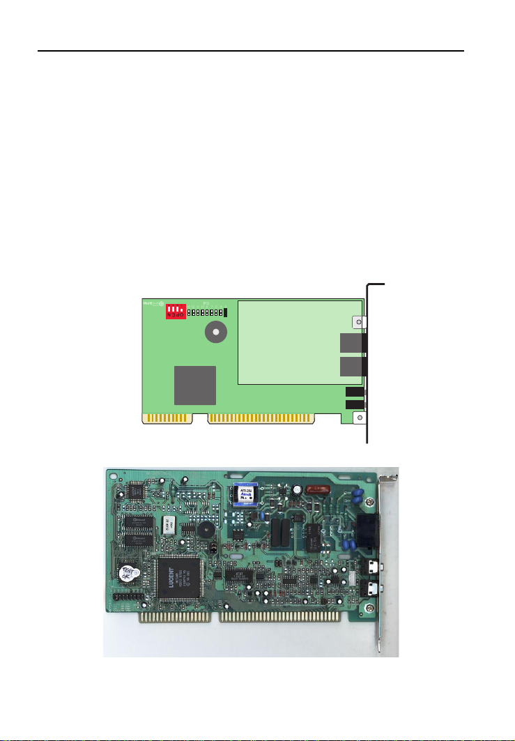
Installation will be slightly different for the two different circuit
boards (Type 1 or Type 2) commonly used in the MT5634ZPX.
The Type 1 board contains a four-position DIP switch for COM
port assignment and nine Berg jumpers for setting the IRQ
address. On the Type 1 board, the DIP switch and jumpers are
located at the upper left corner of the PC board (see Figure 2-1).
The factory default for the Type 1 board is Plug-N-Play
(automatic COM port and IRQ address assignment). See
FIgure 2-3.
The Type 2 board contains a bank of three Berg jumpers for
COM port assignment and a bank of eight Berg jumpers for
setting the IRQ address. The COM port jumpers are in the lower
left corner of the board (Figure 2-2); the IRQ jumpers are near
the center of the board (Figure 2-2). The factory default for the
Type 2 board is Plug-N-Play operation (see Figure 2-4). For
non-Plug-N-Play operation, the user can re-position the COM
MT5634ZPX
17
Owner’s Manual
port jumpers and IRQ jumpers manually as needed. The COM
port jumpers allow manual assignment of COM2, COM3, or
COM4 and IRQ values of 3, 4, 5, 7, 9, 10, 12, and 15.
Installing the MultiModemZPX consists of four steps:
1. Configuring the modem’s DIP-Switch and Jumper settings
2. Installing the modem in the computer
3. Connecting the modem to the telephone line and, optionally,
to an external speaker and microphone
4. Installing the modem’s drivers
Note: Unless otherwise noted, these procedures are for both PnP
and nonPnP environments.
18
Figure 2-1. MultiModemZPX (Type 1 Board)
Figure 2-2. MultiModem ZPX (Type 2 Board)
MT5634ZPX
2 Installation
Configure the MultiModemZPX DIP-Switches
and Jumpers
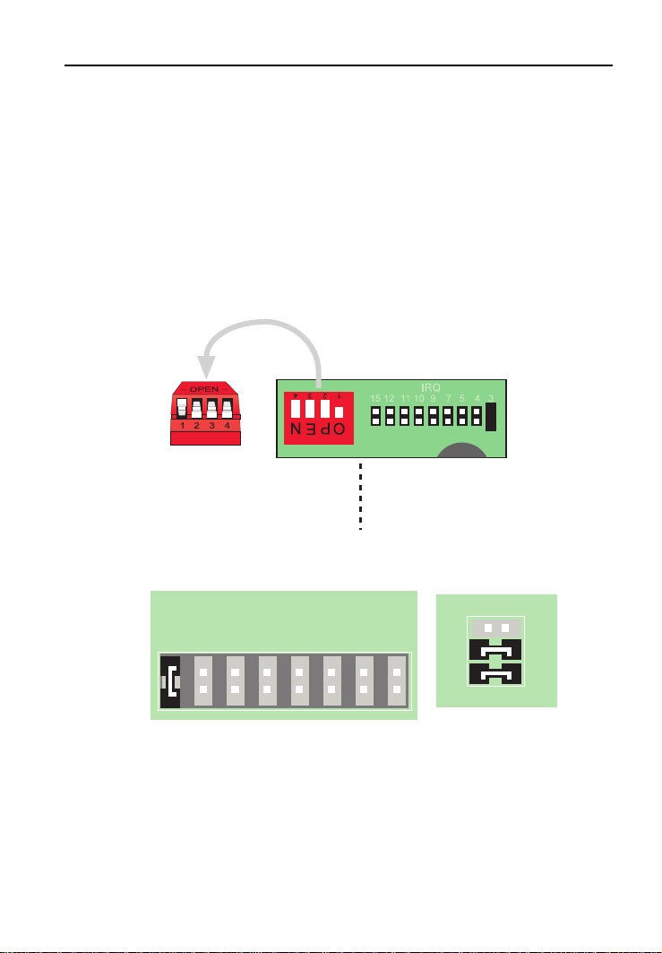
Windows 95 Plug and Play
The Type 1 and Type 2 MT5634ZPX Modem boards are both
shipped from the factory already configured for Plug-and-Play
(PnP) operation. If you want PnP, do not change the jumpers or
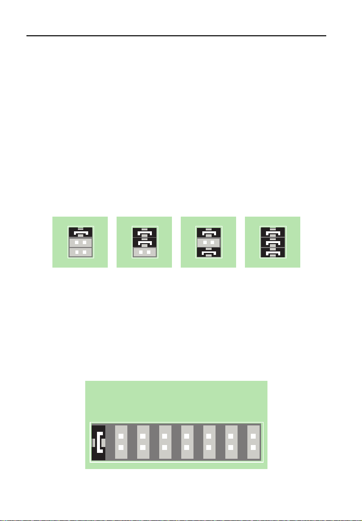
DIP switches on the board. Figures 2-3 and 2-4 show switches
and jumpers for PnP configuration.
Plug-N-Play
COM Port
Setting
Plug-N-Play
IRQ Setting
Figure 2-3. Plug and Play -- Type 1 Board
2
1
IRQ15
IRQ12
IRQ10
IRQ9
IRQ7
IRQ5
IRQ4
IRQ3
6
5
Plug-N-Play
Plug-N-Play IRQ Setting
COM Port Setting
Figure 2-4 Plug and Play -- Type 2 Board
Unlike an external modem, the MultiModemZPX contains its own
serial port. When Windows 95 detects the MultiModemZPX, it
MT5634ZPX
19

Owner’s Manual
assigns the next available COM port number to it. Since COM1
and COM2 are standard serial ports in Windows computers,
Windows 95 typically assigns COM3 to the MultiModemZPX’s
serial port. Windows 95 also assigns the MultiModemZPX a port
address and interrupt request (IRQ) number. Because the
number of IRQs is limited, a computer with several accessories
may not have an available IRQ for your new modem. In that
case, you may have to decide which of your other accessories
you can modify or do without.
20
MT5634ZPX

2 Installation
Non PnP
The MultiModemZPX can be configured for Windows Plug and
PlayTM (PnP) environments as well as nonPnP environments. If
you have MS-DOS 6.0 or later, you can find your current COM
Port settings from a diagnostic program called
type MSD at the DOS prompt. After the opening screen, select
COM Ports. A list of current device Port Addresses appears with
available COM Ports. Be sure that all settings are correct before
proceeding with the installation.
MSD
. To use it,
MT5634ZPX
21

Owner’s Manual
Non-PnP COM Ports & IRQ Address -- Type 1 Board
Figure 2-5. Four-position DIP-Switch (Type 1Board)
DIP # Position Effect
1 Open (Up)* Selects Plug and Play
Closed (Down) Selects Non-Plug and Play
2&3 2 Open Base Address = 3F8 COM 1
3 Open
2 Closed Base Address = 2F8 COM 2
3 Open
2 Open Base Address = 3E8 COM 3
3 Closed
2 Closed* Base Address = 2E8 COM 4
3 Closed*
4 Reserved for future use
* Factory Default Setting
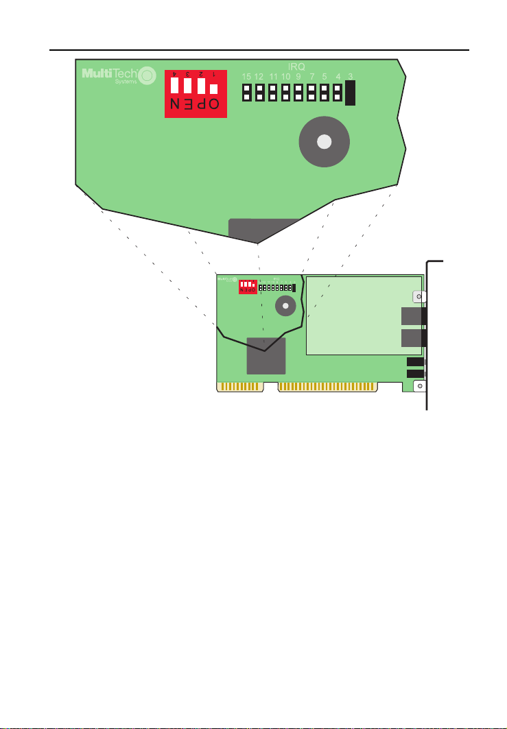
After you have selected the desired COM Port via the 4-position
DIP-switch, you must assign an IRQ address by placing the IRQ
jumper in the desired position. Figure 2-6 shows the jumper and
DIP-switch in the default positions for PnP.
Note: The jumper must be in the default position (IRQ3) for PnP.
22
MT5634ZPX
2 Installation
Figure 2-6. Default DIP/Jumper (Type 1 Board)
Select the IRQ for your COM port by moving the supplied
shorting plug, or jumper, to the two pins above the desired IRQ
number. Select an address and an IRQ that does not conflict
with others in your computer. Supported IRQ values for the
MT5634ZPX include 3,4,5,7,9,10,11,12, and 15.
MT5634ZPX
23
Owner’s Manual
Non-PnP COM Ports & IRQ Address --Type 2 Board
If you alter the Type 2 board factory setting (PnP) only by
repositioning the top jumper to bridge the “1-2” pins, the resulting
configuration is IRQ=3 on COM 4. This can be considered the
default setting for non-PnP operation. Other configurations can
be chosen as shown in Figure 2-7.
The COM port for the Type 2 board is set using the bank of three
Berg jumpers. The first position of the jumper bank, when
occupied, selects the Non-Plug-N-Play mode. The other
positions are used to set the COM port. See Figure 2-7
(* denotes the factory default setting for non-PnP operation).
These configurations are also marked on the board itself, below
the IRQ jumper bank.
2
1
6
5
2
1
6
5
2
1
6
5
2
1
6
5
Non-Plug-N-Play COM 2
COM 3 COM 4*
Figure 2-7. COM Port Jumpers (Type 2 Board)
To assign an IRQ address, place the IRQ jumper in the desired
position. Figure 2-8 shows the jumpers in the default position of
IRQ3. The IRQ address you chose should be one that does not
conflict with others used by other devices connected to your
computer. The MT5634ZPX Type 2 board supports these
values: 3, 4, 5, 7, 9, 10, 12, and 15.
IRQ15
IRQ12
IRQ10
IRQ9
IRQ7
IRQ5
IRQ4
IRQ3
Figure 2-8. IRQ Jumpers (Type 2 Board)
24
MT5634ZPX

2 Installation
Sound Card Considerations
If you want speakerphone functions along with the ability to
record sound or .WAV files through the sound card at the same
time, you need:
• two stereo PC microphones
• one stereo male-to-male patch cord
• one sound card and optional speakers
To connect a 3rd party sound card, follow the steps below:
1. Obtain a stereo male-to-male patch cord (can be purchased
at a local PC retail store).
2. Place one end of a stereo male-to-male patch cord into the
LINE OUT jack of the MultiModemZPX and the other end
into the LINE IN jack of the sound card. This lets you hear
the activity of the modem, whether it is originating or
answering a call or playing a recorded message using the
bundled Trio software.
3. Place the two stereo microphones (do not use mono
microphones) far enough apart from each other to eliminate
feedback (e.g., one on each side of the monitor). Feedback
only occurs if the microphones are too close to each other.
Make sure speakers are amplified with power source being
either a battery or AC outlet.
4. Place the microphone and speakers far enough apart from
each other to eliminate feedback. Plug the connector of both
microphones into the MIC IN jack of both the SoundCard
and the MultiModemZPX.
MT5634ZPX
25

Owner’s Manual
Install the MultiModemZPX into the Computer
Installation of the MultiModemZPX requires you to open your
computer. Please consult the computer manual in addition to the
following instructions:
1. Turn off the computer and unplug it. Failure to do so may
result in damage to both the MultiModemZPX and the
computer. Do not turn the computer on until the instructions
tell you to do so.
2. Remove the cover from the computer as instructed in the
computer manual.
3. Select an empty 16-bit half- or full-size ISA expansion slot.
Remove the expansion slot cover and save the retaining
screw.
4. Before handling the MultiModemZPX, discharge any static in
your body by touching a piece of grounded metal such as a
water faucet. Carefully remove the MultiModemZPX from its
antistatic bag, handling it only by the mounting bracket and
edges. Do not touch the gold-plated connectors along the
bottom edge.
5. Placing the MultiModemZPX directly above the expansion
slot, gently but firmly push it into the connector until the
card’s retaining bracket is flush against the computer
chassis.
6. With the screw you saved in step 3, fasten the retaining
bracket to the computer chassis.
7. Replace the cover of the computer.
26
MT5634ZPX

2 Installation
External Connections
The MultiModemZPX communicates over public-switched
telephone network lines. Use the modular telephone cable
provided with the modem to connect the MultiModemZPX to
your telephone wall jack. If you do not have a standard modular
wall jack near your computer, you should install one or have one
installed for you by your telephone company. In the U.S.,
installation kits and adapters are available wherever telephones
are sold.
If you want, you can use a microphone and speaker with the
MultiModemZPX. The microphone can be used for recording
answering machine messages or for speakerphone use. The
speaker can be used for playing back messages or for
speakerphone use.
MT5634ZPX
27
Owner’s Manual
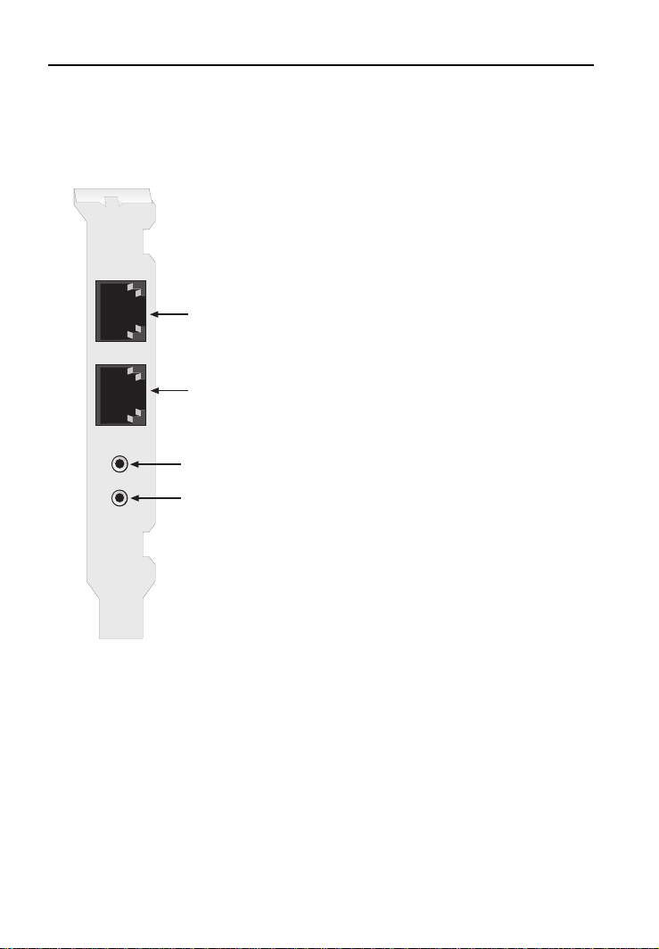
Cabling for Type 1 Board
To cable the MultiModem ZPX Type 1 PC Board:
1. Plug one end of the supplied
modular telephone cable into the
MultiModemZPX's LINE jack.
2. Plug the other end of the phone
cable into a working wall jack.
3. If you want to connect a telephone
LINE
to your modem, plug the telephone’s
line cable into the MultiModemZPX's
PHONE jack.
PHONE
MIC IN
LINE OUT
4. If you want to use a microphone
and/or speaker with the
MultiModemZPX, connect a
microphone by inserting the
microphone plug into the modem's
MIC IN jack.
5. To connect a speaker or
headphone, insert the speaker
or headphone plug into the
modem's LINE OUT jack.
28
MT5634ZPX
2 Installation
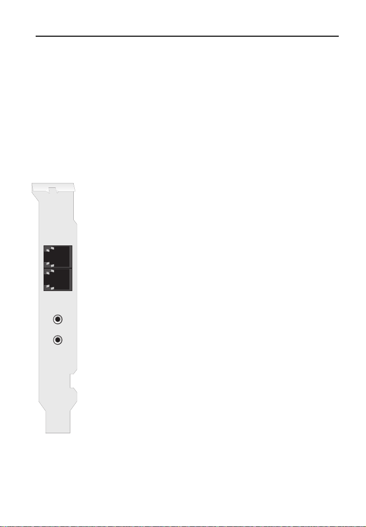
Cabling for Type 2 Board
The MultiModem ZPX communicates over public-switched
telephone network lines. Use the modular telephone cable
provided with the modem to connect the MultiModem ZPX to
your telephone wall jack.
If you want, you can use a microphone and speaker with the
MultiModem ZPX. The microphone can be used for recording
answering machine messages or for speakerphone use. The
speaker can be used fro playing back messages or for
speakerphone use.
To cable the MultiModem ZPX Type 2 PC Board:
1. Plug one end of the supplied modular telephone
cable into the MultiModem ZPX’s LINE jack.
PHONE
LINE
2. Plug the other end fo the phone cable into a working
wall jack.
3. If you want to connect a telephone to your modem,
plug the telepone’s line cable into the MultiModem ZPX’s
PHONE jack.
SPK
MIC
MT5634ZPX
4. If you want to use a microphone and/or speaker witht
eh MultiModem ZPX, connect a microphone by inserting
the microphone plug into the modem’s MIC jack.
5. To connect a speaker or headphone, insert the
speaker or headphone plug into the modem’s SPK jack.
29

Owner’s Manual
Installing Drivers
1. Plug in and turn on your computer. As your computer boots,
it automatically detects the MultiModemZPX, and the
Hardware Found
dialog box appears.
New
2. In the
3. Insert the MultiModemZPX Drivers disk into your computer's
4. Installation of the MultiModemZPX is complete. If you plan to
New Hardware Found
disk provided by hardware manufacturer
selection). Then click OK. The
appears.
floppy drive, select the drive letter (A:\ is the default), and
click OK. The computer installs the software drivers needed
to communicate with your MultiModemZPX and then
displays the Windows 95 desktop.
use the provided communications software, install it now
according to the instructions provided in your corresponding
software manual.
dialog box, select
(the default
Install from Disk
Driver from
window
Verifying Configuration
Windows 95 Plug and Play
Use the following procedure to check the assignments Windows
has made for your modem:
1. Click
Start
, point to
double-click the
Settings
System
icon.
, click
Control Panel
, and
2. When the
Manager
3. Double-click
computer.
4. Double-click
Properties sheet for your particular MultiModemZPX model
appears.
30
System Properties
tab. A list of device types appears.
Modem
for a list of modems installed in your
Multi-Tech MT5634ZPX
sheet appears, click the
. The Modem
Device
MT5634ZPX
 Loading...