

Multitech MT5634ZLXI/E Product Update
MultiMobile
MT5634ZLXI/E
P
RODUCT UPDATE
Tec
Systems
®
h
PN 82086600, REV. A
The MT5634ZLXI/E is the International version of the MT5634ZLX/E card, with the addition of global telecom approvals. This
product is local-government approved in many countries in Europe, the Americas, Asia, Australia, and other regions of the
world. This document covers the differences in the installation and operation of the MT5634ZLXI/E.
MT5634ZLXI/E SHIP KIT CONTENTS
The MT5634ZLXI/E is shipped with the following:
· one MT5634ZLXI/E PC Card
· one 15-pin MT56ZLXI-MODEM-LAM
· one 15-pin MT56ZLXI-ETHERNET-LAM
· one application software CD
· one diskette with device drivers and Global Wizard
· one 7 phone cord with an RJ-11 plug
· an owners manual (possibly with product updates)
MT5634ZLXI/E LAM INFORMATION
The MT5634ZLXI/E is shipped with two LAMs (Loader Access Modules) that are required for connecting the modem to the
PSTN (Figure 1) and to the Ethernet LAN (Figure 2).
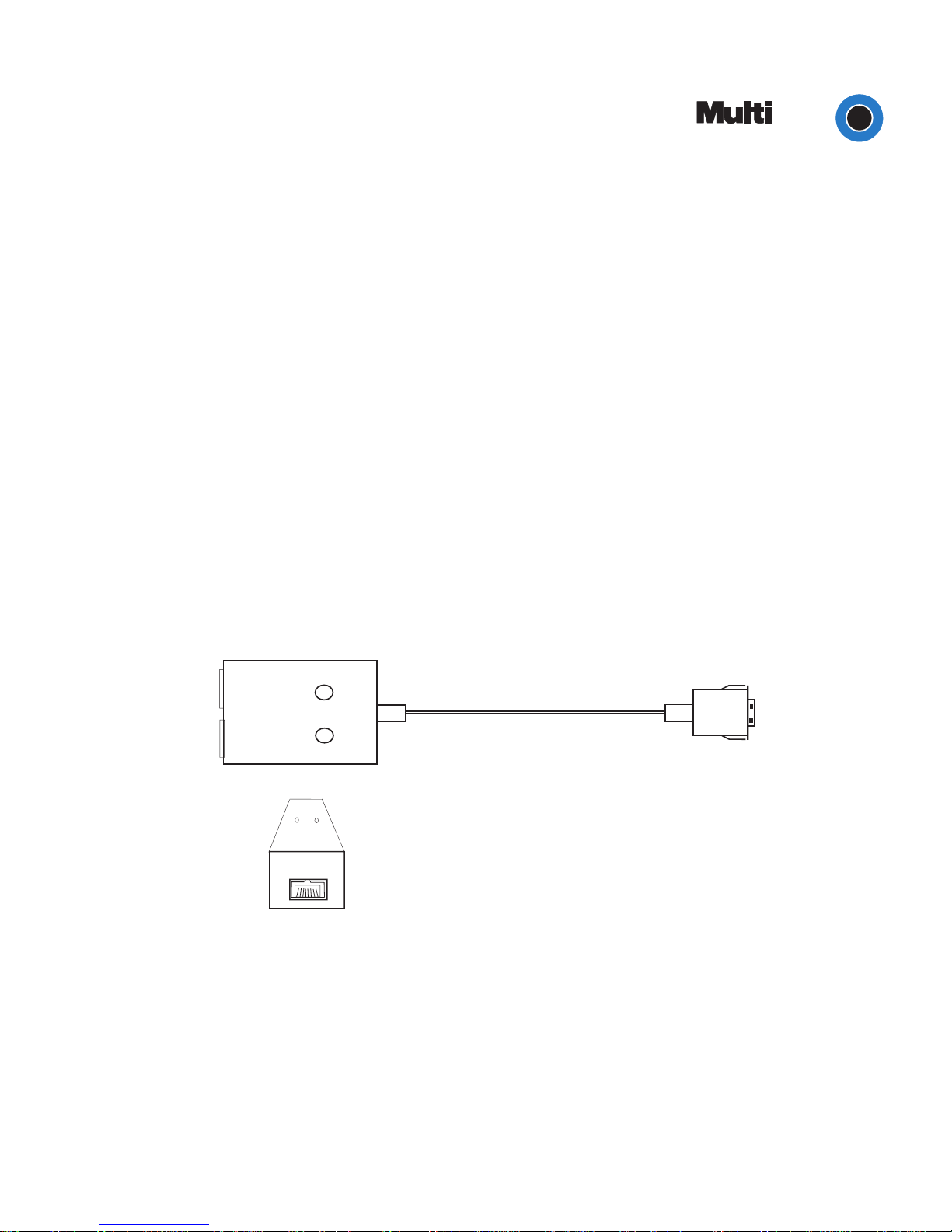
The Ethernet LAM connects the MT5634ZLXI/E to the Ethernet LAN. It has a keyed connector (labeled Press Down to
Release) at the PC Card side, and an RJ-45 connector at the Ethernet LAN side. The Ethernet LAM has 2 LEDs, labeled Act
and Link.
Act
Link
DOWN
TO
RELEASE
PRESS
Figure 1. The MT5634ZLXI/E Ethernet LAM
1
PRODUCT UPDATE
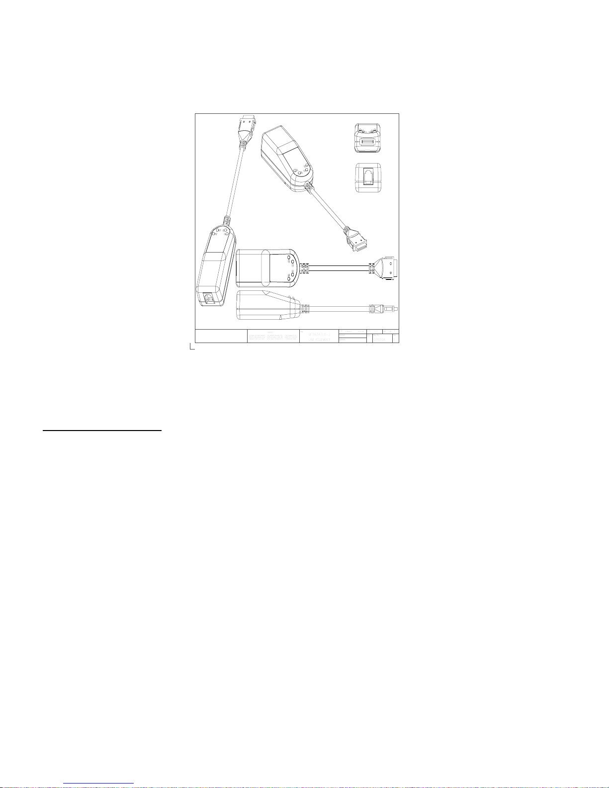
The MODEM-LAM is slightly longer than the Ethernet LAM. The MODEM-LAM has a keyed connector at the PC Card side,
and an RJ-11 connector at the PSTN side. The MODEM-LAM has 4 LEDs, labeled TD, RD, CD, and OH.
Figure 2. The MT5634ZLXI/E MODEM-LAM
MT5634ZLXI/E Installation
1. Insert the MT5634ZLXI/E into the computers PCMCIA slot with the 68-pin connector facing the PCMCIA slot and the
label facing up and slide the card into the slot.
2. Install the appropriate device driver from the Device Driver/Global Wizard diskette.
3. Run the Global Wizard software from the Device Driver/Global Wizard diskette.
4. Plug the 15-pin MODEM-LAM into the 15-pin Modem socket of the PC card; connect the other end of the MODEMLAM to the telephone system (PSTN) by plugging an RJ-11 cable plug into the MODEM-LAMs 4-pin RJ11 receptacle,
and plug the other end of the RJ11 cable into an available PSTN receptacle.
5. Plug the 15-pin Ethernet-LAM into the 15-pin Modem socket of the PC card; connect the other end (8-pin RJ-45) of the
Ethernet-LAM to the Ethernet LAN using UTP or STP cable.
6. With the PC powered on, verify MT5634ZLXI/E LED operation.
2
 Loading...