

Multitech MT5634ZBA-USB, MT5634IND, MT5634ZPX-PCI, MT5634ZPX-ISA, ISI5634UPCI Command Reference Manual
...Page 1

MultiModem®
External Modems
MultiModem® ZBA (MT5634ZBA Global and Non-Global Series)
MultiModem® ZBA USB (MT5634ZBA-USB)
MultiModem® IND (MT5634IND)
MultiModem® DID (MT5634ZBA-DID)
Internal Modems
MultiModem® ZPX (MT5634ZPX-PCI Series)
MultiModem® ZPX (MT5634ZPX-ISA)
Server Cards
MultiModem® ISI (ISI5634UPCI Series)
AT Commands
Reference Guide
Page 2

Copyright and Technical Support
AT Commands Reference Guide
Products: External Modems: MT
Internal Modems: MT
Server Cards: ISI5634UP
5634ZBA Series, MT5634ZBA-USB, MT5634IND, MT5634DID
5634ZPX-PCI Series, MT5634ZPX-ISA,
CI Series
Legacy Modems: MT5634ZLX Series
PN S000272H, Version H
Copyright
T
his publication may not be reproduced, in whole or in part, without prior expressed written permission from Multi-
Tech Systems, Inc. All rights reserved. Copyright © 2002-5, by Multi-Tech Systems, Inc.
Multi-Tech Systems, Inc. makes no representations or warranties with respect to the contents hereof and specifically
disclaims any implied warranties of merchantability or fitness for any particular purpose. Furthermore, Multi-Tech
Systems, Inc. reserves the right to revise this publication and to make changes from time to time in the content hereof
without obligation of Multi-Tech Systems, Inc. to notify any person or organization of such revisions or changes.
Revisions
vision Level Date Description
Re
A 10/30/02 Initial release.
B 02/24/03 Change +PIG=0 to enable PCM upstream with default 1.
Add #CBS4. Add +VRID.
C 10/01/03 The guide is now applicable to the ISI5634PCI.
D 11/17/03 This guide is now applicable to the MT5634ZPX-ISA. Explained the default for
the S-Register S0: the default for internal modems is 0 while the default external
modems is 1.
E 01/04/05 Removed \X command. Adde d &L for the MT5634IND. Added Index cross-
references. Changed font.
F 12/30/05 Changed the description of \N1. Added a chapter on setting country codes.
G 04/11/07 Updated the Technical Su pport contact list.
H 12/28/07 Changed Technical Support contact list.
Trademarks
MultiMod
em and the Multi-Tech logo are Registered Trademarks of Multi-Tech Systems, Inc.
World Headquarters
Multi-T
ech Systems, Inc.
2205 Woodale Drive
Mounds View, Minnesota 55112
Phone: 763-785-3500 or 800-328-9717
Fax: 763-785-9874
Technical Support
Country By Email By Phone
e, Middle East, Africa: support@multitech.co.uk +(44) 118 959 7774
Europ
U.S., Canada, all others: suppport@multitech.com (800) 972-2439 or (763) 717-5863
Internet Address: http://www.multitech.com
Multi-Tech Systems, Inc. AT Commands for the MT5634 Family of Products (S000272H) 2
Page 3

Contents
Contents
Chapter 1 - AT Commands............................................................................................................................................4
Introduction..............................................................................................................................................................4
List of General Commands .....................................................................................................................................5
List of V.92 Commands ...........................................................................................................................................6
List of Caller ID Commands ....................................................................................................................................6
List of Callback Commands....................................................................................................................................6
List of Escape Commands ......................................................................................................................................7
List of DID Commands.............................................................................................................................................7
AT Commands Detail...............................................................................................................................................8
V.92 Commands.....................................................................................................................................................17
Caller ID Commands..............................................................................................................................................21
Callback Security Commands...............................................................................................................................22
Escape Sequence Commands..............................................................................................................................23
DID Commands ......................................................................................................................................................24
Chapter 2 - S-Registers...............................................................................................................................................26
Chapter 3 - Result Codes............................................................................................................................................29
Chapter 4 – Setting Your Country or Regional Code................................................................................................30
Global Modem Configuration................................................................................................................................30
Windows® Users..................................................................................................................................................30
Non-Windows® Users..........................................................................................................................................30
MultiModem® Configuration.................................................................................................................................30
Index .............................................................................................................................................................................31
Multi-Tech Systems, Inc. AT Commands for the MT5634 Family of Products (S000272H) 3
Page 4

Chapter 1 – AT Commands
Chapter 1 - AT Comm ands
Introduction
The AT commands are used to control the operation of your modem. They are called AT commands bec ause the
characters AT must precede each command to get the ATtention of the modem.
AT commands can be issued only when the modem is in command mode or online command mode. The modem
is in command mode whenever it is not connected to another modem. The modem is in data mode whenever it is
connected to another modem and ready to exchange data. Online command mode is a tempor ary state in which
you can issue commands to the modem while connected to another modem. To put the modem into online
command mode from data mode, you must issue an escape sequence (+++) followed immediately by the AT
characters and the command, e.g., +++ to hang up the modem. To return to data mode from online command
mode, you must issue the command ATO.
To send AT commands to the modem you must use a communications program, such as the HyperTerminal
applet in Windows 98/95 and NT 4.0, or some other available terminal program. You can issue commands to the
modem either directly, by typing them in the terminal window of the communications program, or indirectly, by
configuring the operating system or communications program to send the commands automatically. Fortunately,
communications programs make daily operation of modems effortless by hiding the commands from the user.
Most users, therefore, need to use AT commands only when reconfiguring the modem, e.g., to turn autoanswer
on or off.
The format for entering an AT command is ATXn, where X is the command and n is the specific value for the
command, sometimes called the command parameter. The value is always a number. If the value is zero, you
can omit it from the command; thus, AT&W is equivalent to AT&W0. Most commands have a default value,
which is the value that is set at the factory.
You must press ENTER (depending on the terminal program it could be some other key) to send the command
to the modem. Any time the modem receives a command, it sends a response known as a result code. The
most common result codes are OK, ERROR, and the CONNECT messages that the modem sends to the
computer when it is connecting to another modem.
You can issue several commands in one line, in what is called a command string. The command string begins
with AT and ends when you press ENTER. Spaces to separate the commands are optional; the command
interpreter ignores them. The most familiar command string is the initialization string, which is used to
configure the modem when it is turned on or reset, or when your communications software calls another modem.
Multi-Tech Systems, Inc. AT Commands for the MT5634 Family of Products (S000272H) 4
Page 5

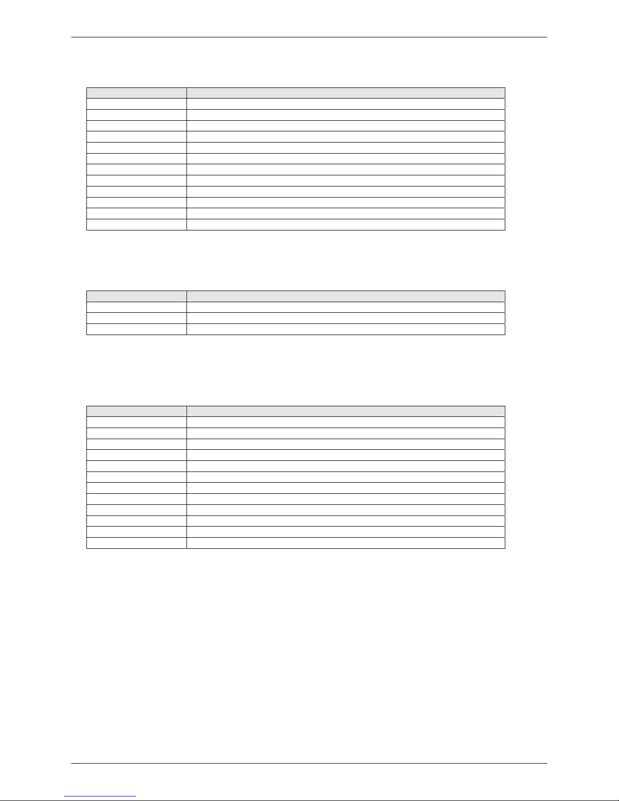
List of General Commands
Command Description
AT Attention Code
A Answer
A/ Repeat Last Command
B Communication Standard Setting – Bell or CCITT
D Dial
%M Enable Dialing Message
DS=n Dial Stored Telephone Number
E Echo Command
F Echo Online Data Characters
H Disconnect (Hang Up)
I Information Request
L Not Applicable
M Monitor Speaker Mode
N Modulation Handshake
O Return to Online Data Mode
P Set Pulse Dial Default
Q Result Codes Enable/Disable
Sr=n Set Register Value
Sr? Read Register Value
T Set Tone Dial Default
V Result Code Format
W Result Code Options
X Result Code Selection
Z Modem Reset
&C Data Carrier Detect (DCD) Control
&D Data Terminal Ready (DTR) Control
&E XON/OFF Pacing Control
&F Restore Factory Settings (Configuration)
&G Select Guard Tone Control
&K Flow Control Selection
&L Leased-Line Operation
&Q Asynchronous Communication Mode (same as \N Error Correction Mode)
&S Data Set Ready (DSR) Control
&T Loopback Tests
&V Display Current Settings (Configuration and Stored Profiles)
&W Store Current Settings (Configuration and Stored Profiles)
&Zn=x Store Dialing Command
\A Select Maximum MNP Block Size
\B Transmit Break to Remote
\K Break Control
\N Error Correction Mode Selection
\Q Flow Control Selection
\T Inactivity Timer
\V Protocol Result Code
-C Data Calling Tone
%A Adaptive Answer Result Code Enable
%B View Numbers in Blacklist
%C Data Compression Enable/Disable
%DC AT Command Control
%DT “AT” Command Timer
%E Fallback and Fall Forward Control
%H Direct Connect Enable
%R Cisco Configuration
%S Response Speed
$D DTR Dialing
$EB Asynchronous Word Length
$LB Long Break
$RP Response Priority
$SB Serial Port Baud Rate
Chapter 1 – AT Commands
Multi-Tech Systems, Inc. AT Commands for the MT5634 Family of Products (S000272H) 5
Page 6
List of V.92 Commands
Command Description
+PCW=n Call Waiting Enable
+PIG=n PCM Upstream Enable
+PMH=n Modem-on-Hold Enable
+PMHF V.92 Modem Hook Flash
+PMHR=n Modem-on-Hold Initiate
+PMHTR=n Modem-on-Hold Timer
+PQC=n Quick Connect Control
+DCS=x,y Select V.44 Data Compression
+DR=n V.44 Data Compression Reporting
+DS44=n V.44 Data Compressio n
+MS Modulation Selection
$FC Quick Connect
List of Caller ID Commands
Command Description
+VCID Caller ID Enable/Disable
+VDR=x,y Distinctive Ring Report “ERROR”
+VRID Allows query of modem’s last call received
Chapter 1 – AT Commands
List of Callback Commands
These commands are used with modems that support Callback Security
Command Description
#CBA Callback Attempts
#CBD Callback Delay
#CBF? Callback Failed Attempts Display
#CBFR Callback Failed Attempts Reset
#CBI Local Callback Inactivity Timer
#CBNy=x Store Callback Password
#CBP Callback Parity
#CBR Callback Security Reset
#CBS Callback Enable/Disable
#P Set 11-bit Parity
#Sx Enter Setup Password
#S=x Store Setup Password
Multi-Tech Systems, Inc. AT Commands for the MT5634 Family of Products (S000272H) 6
Page 7
List of Escape Commands
Command Description
+++AT Escape Sequence
%%%ATMTSMODEM Remote Configuration Escape Sequence
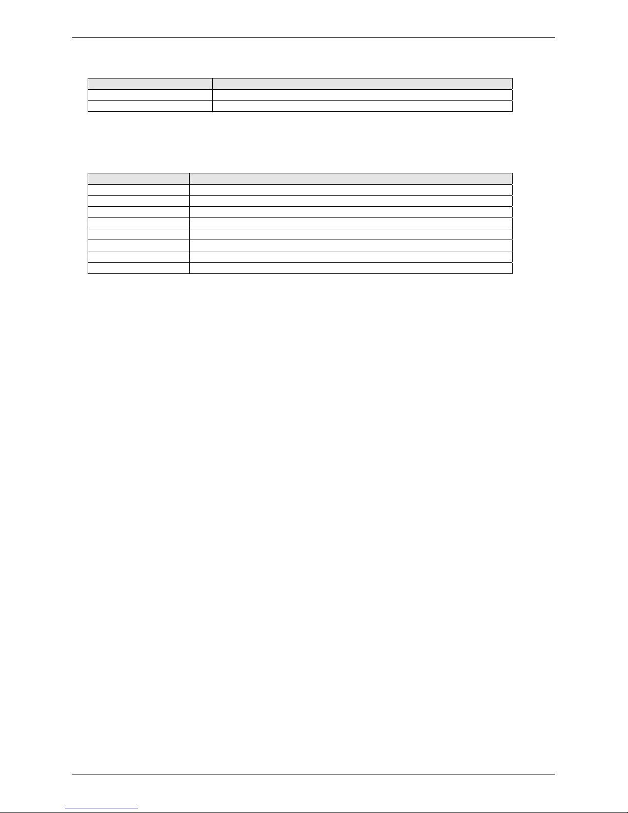
List of DID Commands
Command Description
*DD Digit Format
*DF Format for Reporting Incoming DID Number
*DS Start Protocol
*DT Wait for Digit Time-Out Time
*DW Busy Out After Call Completion
*DN Number of DID Digits
*DW Busy Out After Call Completion
*DN Number of DID Digits
Chapter 1 – AT Commands
Multi-Tech Systems, Inc. AT Commands for the MT5634 Family of Products (S000272H) 7
Page 8

Chapter 1 – AT Commands
AT Commands Detail
Command: AT Attention Code
Values: n/a
Description: The attention code precedes all command lines except A/ and escape sequences.
Command: A Answer
Values: n/a
Description: Answer an incoming call before the final ring.
Command: A/ Repeat Last Command
Values: n/a
Description: Repeat the last command string. Do not precede this command with AT. Do not press E
to execute.
Command: Bn Communication Standard Setting
Values: n = 0-3, 15, 16
Default: 1 and 16
Description: B0 Select ITU-T V.22 mode when modem is at 1200 bps
B1 Select Bell 212A when modem is 1200 bps.
B2 Deselect V.23 reverse channel (same as B3).
B3 Deselect V.23 reverse channel (same as B2).
B15 Select V.21 when modem is at 300 bps.
B16 Select Bell 10 3 when modem is at 300 bps.
NTER
Command: Ds Dial
Values: s = dial string (phone number and dial modifiers)
Default: none
Description: Dial telephone number s, where s may be up to 40 characters long and include these
characters: 0-9, *, #, A, B, C, D
Can also include these D ial String Modifiers: L, P, T, W, S, comma (,), semicolon (;), !, @, ^,
and $.
Dial String Characters and Modifiers
0-9 DTMF digits 0 to 9.
* The 'star' digit (tone dialing only).
# The 'gate' digit (tone dialing only).
A-D Some countries may prohibit sending of these digits during dialing (tone dialing
only)
L Redial last number. (Must be placed immediately after ATD.)
P Selects pulse dialing until a T is encountered. Affects current and subsequent
dialing. Some countries prevent changing dialing modes after the first digit is
dialed.
T Selects tone dialing until a P is encountered. Affects current and subsequent
dialing. Some countries prevent changing dialing modes after the first digit is
dialed.
W Wait for a new dial tone before continui ng to dial. (X2, X4, X5, X6, or X7 must be
selected).
S=n Dial the number stored in the directory (n = 0 to 3). (See &Z.)
, Pause during dialing for set set in in register S8.
; Return to command mode after dialing. Place at the end of dial string.
! Hook Flash. Causes the modem to go on-hook for a time defined by the value of
S29, then off-hook again. Country requirements may limit the time imposed.
@ Wait for quiet answer (silence). Causes the modem to wait for a ring back, then 5
seconds of silence before processing the next part of the command. If silence is
not detected, the modem returns a NO ANSWER code.
^ Toggles the calling tone between enable/disable. Applicable to current dial
attempt only.
$ Detect AT&T call card “bong” tone. The character should fol low the phone
number and precede the user’s call card number:
ATDT1028806127853500$123456789
Multi-Tech Systems, Inc. AT Commands for the MT5634 Family of Products (S000272H) 8
Page 9

Chapter 1 – AT Commands
Ignored Characters
( ) Ignored: may be used to format the dial string.
- Ignored: may be used to format the dial string.
<space> Ignored: may be used to format the dial string.
<i> Invalid character: will be ignored.
Command: %M Enable Dialing Message
Values: 0, 1
Default: 0
Description: Enables dialing message. It will display when the ATDL=n command is used and dialing
from memory or DTR dialing.
0 = Disabled - turns diali ng message off
1 = Enabled - turns dialing message on
Command: DS=n Dial Stored Telephone Number
Values: n = 0, 1, 2
Default: none
Description: Dials a number previously stored in the directory by the &Zn=x command. Ex: ATDS=2.
Command: En Echo Command
Values: n = 0 or 1
Default: 1
Description: E0 Disables echo command.
E1 Enables echo command.
Command: Fn Echo Online Data Characters
Values: n = 0, 1
Default: 1
Description: F0 Enables online data character echo. (Not supported.)
F1 Disables online data character echo (included for backward compatibility).
Command: Hn Disconnect (Hang Up)
Values: n = 0 or 1
Default: 0
Description: H0 The modem goes on-hook (hangs up).
H1 The modem goes off-hook (makes the phone line busy).
Command: In Information Request
Values: n = 0–5, 9, 11
Default: None
Description: I0 Displ ays default speed and controller firmware version.
I1 Calculates and displays ROM checksum (e.g., B399).
I2 Checks ROM and verifies the checksum, displaying OK or ERROR.
I3 Displays default speed and controller firmware version.
I4 Displays firmware version for data pump (e.g., 17)..
I5 Displays the board ID: software version, hardware version, and the country ID in
hexidecimal format (e.g., s0503a01V, 0,34).
I7 Displays release information and V.92 capabilities.
I9 Displa ys the country code in decimal format (e.g., 52).
I11 Displays diagnostic information for the last modem connection, such as DSP and
firmware version, link type, line speed, serial speed, type of error correction/data
compression, number of past retrains, etc.
Command: Ln Not Applicable
Command: Mn Monitor Speaker Mod e
Values: n = 0, 1, 2, or 3
Default: 1
Description: M0 Speaker always off.
M1 Speaker on until carrier signal detected.
M2 Speaker always on when modem is off-hook.
M3 Speaker on until carrier is detected, except while dialing.
Multi-Tech Systems, Inc. AT Commands for the MT5634 Family of Products (S000272H) 9
Page 10

Chapter 1 – AT Commands
Command: Nn Modulation Handshake
Values: n = 0 or 1
Default: 1
Description: N0 Modem performs handshake only at communication standard specified by S37 and the
B command.
N1 Modem begins handshake at communication standard specified by S37 and the B
command. During handshake, fallback to a lower speed can occur.
Command: On Return to Online Data Mode
Values: 0, 1, 3
Default: None
Description: O0 Exits online command and returns to data mode (see +++AT escape sequence).
O1 Issues a retrain and returns to online data mode.
O3 Issues a rate renegotiation and returns to data mode.
Command: P Set Pulse Dial Default
Values: P, T
Default: T
Description: Configures the modem for pulse (non-touch-tone) dialing. Dialed digits are puls ed until a T
command or dial modifier is received.
Command: Qn Result Codes Enable/Disable
Values: n = 0 or 1
Default: 0
Description: Q0 Enables result codes.
Q1 Disables result codes.
Q2 Dumb Answer Mode (also known as No Response Answer). Q2 sets the answer
mode to be handled without responses and echo turned off; however, the originate
mode remains intelligent.
Command: Sr=n Set Register Value
Values: r = S-Register number; n varies
Default: None
Description: Sets the value of the register Sr to the value of n, where n is entered in decimal format:
Example: S0=1.
Command: Sr? Read Register Value
Values: r = S-Register number
Default: None
Description: Reads the value of the register Sr and displays it in 3-digit decimal form. Example: S2?
gives the response 043.
Command: T Set Tone Dial Default
Values: P, T
Default: T
Description: Configures the modem DTMF (touch-tone) dialing. Dialed digits are tone dialed until a P
command or dial modifier is received.
Command: Vn Result Code Format
Values: n = 0 or 1
Default: 1
Description: V0 Displays result codes as digits (short form or terse).
V1 Displays result codes as words (long-form or verbose).
Command: Wn Result Code Options
Values: n = 0, 1, 2
Default: 2
Description: W0 CONNECT result code reports serial port speed, disables protocol result codes.
W1 CONNECT result code reports serial port speed, enables protocol result codes.
W2 CONNECT result code reports line speed, enables protocol result codes.
Multi-Tech Systems, Inc. AT Commands for the MT5634 Family of Products (S000272H) 10
Page 11

Chapter 1 – AT Commands
Command: Xn Result Code Selection
Values: n = 0–7
Default: 4
Description: X0 Basic result codes (e.g., CONNECT); does not look for dial tone or busy signal.
X1 Extended result codes (e.g., CONNECT 46000 V42bis); does not look for dial tone or
busy signal.
X2 Extended result codes with NO DIALTONE; does not look for busy signal.
X3 Extended result codes with BUSY; does not look for dial tone.
X4 Extended result codes with NO DIALTONE and BUSY.
X5 Extended result codes with NO DIALTONE and BUSY.
X6 Extended result codes with NO DIALTONE and BUSY.
X7 Basic result codes with NO DIALTONE and BUSY.
Command: Zn Modem Reset
Values: n = 0 or 1
Default: None
Description: Z0 Resets modem to profile saved by the last &W command.
Z1 Same as Z0.
Command: &Cn Data Carrier Detect (DCD) Control
Values: n = 0, 1, or 2
Default: 1
Description: &C0 Forces the DCD circuit to be always high.
&C1 DCD goes high when the remote modem’s carrier signal is detected, and goes low
when the carrier signal is not detected.
&C2 DCD drops on disconnect for time set by S18, then goes high again (for some PBX
phone systems).
Command: &Dn Data Terminal Ready (DTR) Control
Values: n = 0, 1, 2, or 3
Default: 2
Description: &D0 Modem ignores the true status of the DTR signal and responds as if it is always on.
&D1 If DTR drops while in online data mode, the modem enters command mode, issues
an OK, and remains connected.
&D2 If DTR drops while in online data mode, the modem hangs up. If the signal is not
present, the modem will not answer or dial.
&D3 If DTR drops, the modem hangs up and resets as if an ATZ command were issued.
Command: &En XON/XOFF Pacing Control
Values: n = 12 or 13
Default: 12
Description: &E12 Disables XON/XOFF pacing.
&E13 Enables XON/XOFF pacing. (&K4 must also be set.)
Note: &E13 has no effect if hardware control (&K3) is selected.
Command: &Fn Load Factory Settings
Values: n = 0
Default: None
Description: &F0 Loads factory settings as active configurati on .
Note: See also the Z command.
Command: &Gn V.22bis Guard Tone Control
Values: n = 0, 1, or 2
Default: 0
Description: &G0 Disables guard tone.
&G1 Sets guard tone to 550 Hz.
&G2 Sets guard tone to 1800 Hz.
Note: The &G command is not used in North America.
Multi-Tech Systems, Inc. AT Commands for the MT5634 Family of Products (S000272H) 11
Page 12

Chapter 1 – AT Commands
Command: &Kn Flow Control Selection
Values: n = 0, 3, or 4
Defaults: 3
Description: &K0 Disables flow control.
&K3 Enables CTS/RTS hardware flow control.
&K4 Enables XON/XOFF software flow control.
Command: &Ln Leased-Line Operation
Note: This command applies to the MT5634IND (Industrial Temperature Modem)
Values: n = 0, 1, or 2
Defaults: 0
Description: &L0 The modem is set for standard dial-up operation.
&L1 The modem is set for leased line operation in originate mode.
&L2 The modem is set for leased l ine operation in answer mode.
Note: For &L1 and &L2, there is a 30-second window between power up and the starting of
the leased line handshake. During this time, you can turn off the command, if desired.
Command: &Qn Asynchronous Communications Mode
Values: n = 0, 5, 6, 8, or 9
Default: 5
Description: &Q0 Asynchronous with data buffering. Same as \N0.
&Q5 Error control with data buffering. Same as \N3.
&Q6 Asynchronous with data buffering. Same as \N0.
&Q8 MNP error control mode. If MNP error control is not established, the modem falls
back according to the setting in S36.
&Q9 V.42 or MNP error control mode. If neither error control is established, the modem
falls back according to the setting in S36.
Command: &Sn Data Set Ready (DSR) Control
Values: n = 0 or 1
Default: 0
Description: &S0 DSR is always high (on).
&S1 DSR goes high only during a connection.
Command: &Tn V.54 Test Commands
Values: n = 0, 1, 3 or 6
Default: None
Description: &T0 Abort. Stops any test in progress.
&T1 Initiates local analog loopback test.
&T3 Initiates local digital loopback test.
&T6 Initiates remote digital loopback test.
Note: To stop a test, use the escape sequence (+++AT) before typing &T0.
Command: &V Display Current Settings
Values: n/a
Description: Displays the active modem settings, including the callback security settings if callback
security is enabled. If the setup password has been entered, it also displays the callback
security passwords.
Command: &Wn Store Current Configuration
Values: n = 0, 1
Default: 1
Description: &W0 Stores current modem settings in nonvolatile memory and causes them to be loaded
in place of the factory defaults at power-on or following the ATZ command. See also
the &F command.
&W1 Clears user default settings from nonvolatile memor y and causes the factory defaults
to be loaded at power-on or following the ATZ command.
Multi-Tech Systems, Inc. AT Commands for the MT5634 Family of Products (S000272H) 12
Page 13

Chapter 1 – AT Commands
Command: &Zn=x Storing a Dialing Command
Values: n = 0–3. Callback security disabled. 0, 1 used by MultiModemZPX/ZLI.
0, 1, 2 used by MultiModemZBA.
0–29. Callback security enabled.
x = Stored telephone n umber
Default: None
Description: Stores dialing command x in memory. Dial the stored number using the command ATDS=n.
See also the #CBSn command.
Command: \An Select Maximum MNP Block Size
Values: n = 0, 1, 2, or 3
Default: 3
Description: \A0 64-character maximum.
\A1 128-character maximum.
\A2 192-character maximum.
\A3 256-character maximum.
Command: \Bn Transmit Break
Values: n = 0–9 in 100 ms units
Default: 3
Description: In non-error-correction mode only, sends a break signal of the specified length to a remote
modem. Works in conjunction with the \K command.
Command: \Kn Break Control
Values: n = 0–5
Default: 5
Description: Controls the modem’s response to a break received from the computer, the remote modem,
or the \B commnd. The response is different for each.
Data mode. Modem receives the break from the computer:
\K0 Enters online command mode, no break sent to the remote modem.
\K1 Clears data buffers and send break to the remote modem.
\K2 Same as \K0.
\K3 Sends break immediately to the remote modem .
\K4 Same as \K0.
\K5 Sends break to the remote modem in sequence with the transmitted data.
Data mode. Modem receives the break from the remote modem:
\K0 Clears data buffers and sends break to the computer.
\K1 Same as \K0.
\K2 Sends break immediately to the computer.
\K3 Same as \K2.
\K4 Sends break to the computer in sequence with the received data.
\K5 Same as \K4.
Online command mode. Modem receives a \Bn command from the computer:
\K0 Clears data buffers and sends break to the remote modem.
\K1 Same as \K0.
\K2 Sends break immediately to the remote modem.
\K3 Same as \K2.
\K4 Sends break to the remote modem in sequence with the transmitted data.
\K5 Same as \K4.
Command: \Nn Error Correction Mode Selection
Values: n = 0–5, or 7
Default: 3
Description: \N0 Non-error correction mode with data buffering (same as &Q6).
\N1 For compatibility. Operates the same as \N0.
\N2 MNP reliable mode. If modem cannot make MNP connection, it disconnects.
\N3 V.42/MNP auto-reliable mode. The modem attempts first to connect in V.42 error
\N4 V.42 reliable mode.If the modem cannot make a V.42 connection, it disconnects.
\N5 V.42, MNP, or non-error correction (same as \N3).
\N7 V.42, MNP, or non-error correction (same as \N3).
Multi-Tech Systems, Inc. AT Commands for the MT5634 Family of Products (S000272H) 13
correction mode, then in MNP mode, and finally in non-error-correction (buffer)
mode with continued operation.
Page 14

Chapter 1 – AT Commands
Command: \Qn Flow Control Selection
Values: n = 0, 1, or 3
Default: 3
Description: \Q0 Disables flow control (same as &K0).
\Q1 XON/XOFF software flow control (same as &K4).
\Q2 CTS-only flow control. Not supported.
\Q3 RTS/CTS hardware flow control (same as &K3).
Command: \Tn Inactivity Timer
Values: n = 0, 1–255
Default: 0
Description: \Tn Sets the time (in minutes) that the modem waits after the last character is sent or
received before it disconnects. A value of zero disables the timer. Applies only in
buffer mode.
Note: You can also set the inactivity timer by changing the value of S30.
Command: \Vn Protocol Result Code
Values: n = 0, 1, or 2
Default: 1
Description: \V0 Disables the appending of the protocol result code to the DCE speed.
\V1 Enables the appending of the protocol result code to the DCE speed.
\V2 Same as \V1.
Command: -Cn Data Calling Tone
Values: n = 0 or 1
Defaults: 0
Description: -C0 Disables V.25 data calling tone to deny remote data/fax/voice discrimination.
-C1 Enables V.25 data calling tone to allow remote data/fax/voice discrimination.
Command: %A Adaptive Answer Result Code Enable
Values: n = 0 or 1
Default: 0
Description: The %A command controls whether the DATA and FAX result codes will be sent by the
modem. The modem must be in fax mode for this command to work. Also, the modem must
be set to +FAA=1, which enables the modem to distinguish between a fax and a data cal l.
When these commands are enabled, the modem sends DATA to the computer when it
detects data tones, and FAX when it detects fax tones. These strings are used by some
servers to select the appropriate communication program.
%A0 Disables adaptive answer result codes.
%A1 Enables adaptive answer result codes.
Note: For descriptions of the +FAA= and other fax commands, see the Multi-Tech Fax Class
2.1 Developer’s Guide.
Command: %B View Numbers in Blacklist
Values: n/a
Description: If blacklisting is in effect, AT%B displays the numbers for which the last call attempted in the
previous two hours failed. In countries that do not require blacklisting, the ERROR result
code appears.
Command: %Cn Data Compression Control
Values: n = 0 or 1
Default: 1
Description: %C0 Disable sV.42bis/MNP 5 data compression.
%C1 Enables V.42bis/MNP 5 data compressi on.
Command: %DCn AT Command Control
Values: n = 0 or 1
Default: 0
Description: %DC0 The modem responds to AT commands.
%DC1 The modem ignores AT commands.
Note: The modem will respond to AT%DC for 10 seconds after it is turned on.
Multi-Tech Systems, Inc. AT Commands for the MT5634 Family of Products (S000272H) 14
Page 15

Chapter 1 – AT Commands
Command: %DTn Set Command Mode Time
Values: 0-255 in 1 second increments
Default: 0
Description: Sets the length of time that the command mode will be disabled when set for %DC1 (the
modem ignores AT commands).
Command: %En Fallback and Fall Forward Control
Values: n = 0, 1, or 2
Default: 2
Description: %E0 Disables fallback and fall-forward.
%E1 Enables fallback, disables fall-forward.
%E2 Enables fallback and fall-forward.
Command: %Hn Direct Connect Enable
Values: n = 0, 1
Default: 0
Description: %H0 Sets callback security to normal operation.
%H1 All callback securit y calls will be direct connect regardless of whether the password
or phone number has the - character.
Command: %Rn Cisco Configuration
Values: n = 0, 1
Default: 0
Description: %R0 Disables Cisco configuration.
%R1 Sets E0, Q1, &D0, \N0, $SB9600, and %S1 for operati on with a Cisco router.
Command: %Sn Command Speed Response
Values: n = 0, 1
Default: 0
Description: %S0 Sets modem to respond to AT commands at all normal speeds.
%S1 AT commands accepted at 115200 bps only. Other speeds are ignored.
Command: $Dn DTR Dialing
Values: n = 0 or 1
Default: 0
Description: $D0 Disables DTR dialing.
$D1 Dials the number in memory location 0 when DTR goes high.
Command: $EBn Asynchronous Word Length
Values: n = 0 or 1
Default: 0
Description: $EB0 Enables 10-bit mode.
$EB1 Enables 11-bit mode.
Command: $FC Quick Connect
Values: n = 0, 1, or 2
Default: 1
Description: $FC0 - Sets quick connect at 1200 baud
$FC1 - No quick connect
$FC2 - Sets quick connect at 2400 baud
Command: $LB Long Break
Values: 0-255 in 10 ms increments
Default: 30 (300 ms break)
Description: Sets the length of a long break transmitted by the modem if set up by the modem.
Multi-Tech Systems, Inc. AT Commands for the MT5634 Family of Products (S000272H) 15
Page 16

Chapter 1 – AT Commands
Command: $MBn Modem Baud Rate
Values: 75, 300, 1200, 2400, 4800, 9600, 14400, 19200, 28800, 33600
Default: 33600
Description: Presets the transmission baud rate for originate operations (i.e., the speed of the modem’s
transmissions over the telephone lines when originating a call). With speed conversion,
transmission speed can be a different baud rate than the serial port speed.
When the modem receives a call from another modem, it automatically switches its phone
line transmission speed to match the calling mode. However, if the MultiModem originates a
call to another modem that is unable to connect at the MultiModem’s baud rate, it
automatically drops to the lower baud rate in an attempt to match that modem’s speed. For
example, if the MultiModem is set for 19200 baud and calls a modem with a top speed of
2400 baud, it drops to 2400 baud.
AT$MB75 = V.23
AT$MB300 = 300 bps
AT$MB1200 = 1200 bps
AT$MB2400 = 2400 bps
AT$MB4800 = 4800 bps
AT$MB9600 = 9600 bps
AT$MB14400 = 14400 bps
AT$MB19200 = 19200 bps
AT$MB28800 = 28800 bps
AT$MB33600 = 33600 bps
Command: $RP Response Priority
Values: n = 0, 1
Default: 1
Description: Configures whether an incoming ring or an AT command will have priority.
$RP0 - AT command will have priority
$RP1 - Incoming call (ring) will have priority
Command: $SBn Serial Port Baud Rate
Values: n = speed in bits per second
Default: 57600
Description: $SB300 Set serial port to 300 bps.
$SB1200 Set serial port to 1200 bps.
$SB2400 Set serial port to 2400 bps.
$SB4800 Set serial port to 4800 bps.
$SB9600 Set serial port to 9600 bps.
$SB19200 Set serial port to 19200 bps.
$SB38400 Set serial port to 38400 bps.
$SB57600 Set serial port to 57600 bps.
$SB115200 Set serial port to 115200 bps.
$SB230400 Set serial port to 230400 bps. (V.92 models only)
Multi-Tech Systems, Inc. AT Commands for the MT5634 Family of Products (S000272H) 16
Page 17

Chapter 1 – AT Commands
V.92 Commands
Command: +PCW=n Call Waiting Enable
Values: n = 0, 1, or 2
Default: 0
Description: Controls the action to be taken upon detection of a call waiting tone in V.92 mode. Values
specified by this command are not modified when an AT&F command is issued.
+PCW=0 Toggles V.24 Circuit 125 and collects Caller ID if enabled by +VCID
+PCW=1 Hangs up
+PCW=2 Ignores V.92 call waiting
+PCW=? Displays the allowed values
+PCW? Displays the current value
Command: +PIG=n PCM Upstream Enable
Values: n = 0 or 1
Default: 1
Description: Controls the use of PCM upstream during V.92 operation. PCM upstream allows faster
upload speeds to a V.92 server.
+PIG=0 Enable PCM upstream
+PIG=1 Disable PCM upstream
+PIG=? Displays the allowed values
+PIG? Displ ays the current value
Command: +PMH=n Modem on Hold Enable
Values: n = 0 or 1
Default: 1
Description: Controls if modem on hold procedures are enabled during V.92 operation. Normally
controlled by a modem on hold program. Values specified by this command are not modified
when an AT&F command is issued.
+PMH=0 Enables V.92 modem on hold
+PMH=1 Disables V.92 modem on hold
+PMH=? Displays the allowed values
+PMH? Displays the current value
Command: +PMHF V.92 Modem Hook Flash
Values: n/a
Default: n/a
Description: Causes the DCE to go on-hook for a specified period of time, and then return off-hook for at
least a specified period of time. The specified period of time is normally one-half second, but
may be governed by national regulations. “ERROR” is returned if MOH is not enabled.
Command: +PMHR=n Modem on Hold Initiate
Values: n = 0–13
Default: 0
Description: +PMHR is an action command that causes the modem to initiate MOH with the central site
modem. It returns the following values to indicate negotiated values. Valid only if MOH is
enabled and the modem is off-hook or in data mode. Otherwise, ERROR will be returned.
+PMHR=0 Deny MOH request
+PMHR=1 Grant MOH request with 10 second timeout
+PMHR=2 Grant MOH request with 20 second timeout
+PMHR=3 Grant MOH request with 30 second timeout
+PMHR=4 Grant MOH request with 40 second timeout
+PMHR=5 Grant MOH request with 1 minute timeout
+PMHR=6 Grant MOH request with 2 minute timeout
+PMHR=7 Grant MOH request with 3 minute timeout
+PMHR=8 Grant MOH request with 4 minute timeout
+PMHR=9 Grant MOH request with 6 minute timeout
+PMHR=10 Grant MOH request with 8 minute timeout
+PMHR=11 Grant MOH request with 12 minute timeout
+PMHR=12 Grant MOH request with 16 minute timeout
+PMHR=13 Grant MOH request with indefinite timeout
+PMHR=? Displays the allowed values
+PMHR? Displays the current value
Multi-Tech Systems, Inc. AT Commands for the MT5634 Family of Products (S000272H) 17
Page 18

Chapter 1 – AT Commands
Command: +PMHT=n Modem on Hold Timer
Values: n = 0–13
Default: 0
Description: Determines if the modem will accept a V.92 Modem on Hold request; sets the MoH timeout.
+PMHT=0 Deny MOH request
+PMHT=1 Grant MOH request with 10 second timeout
+PMHT=2 Grant MOH request with 20 second timeout
+PMHT=3 Grant MOH request with 30 second timeout
+PMHT=4 Grant MOH request with 40 second timeout
+PMHT=5 Grant MOH request with 1 minute timeout
+PMHT=6 Grant MOH request with 2 minute timeout
+PMHT=7 Grant MOH request with 3 minute timeout
+PMHT=8 Grant MOH request with 4 minute timeout
+PMHT=9 Grant MOH request with 6 minute timeout
+PMHT=10 Grant MOH request with 8 minute timeout
+PMHT=11 Grant MOH request with 12 minute timeout
+PMHT=12 Grant MOH request with 16 minute timeout
+PMHT=13 Grant MOH request with indefinite timeout
+PMHT=? Displays the allowed values
+PMHT? Displays the current value
Command: +PQC=n Quick Connect Control
Values: n = 0, 1, 2, or 3
Default: 3
Description: Controls the V.92 shortened Phase 1 and Phase 2 startup procedures (Quick Connect).
When line conditions are stable, quick connect results in shortened connect times; however,
significant fluctuation in line conditions from call to call can result in longer connect times, in
which case it may be advisable to disable quick connect.
+PQC=0 Enables Short Phase 1 and Short Phase 2 (Quick Con nect)
+PQC=1 Enables Short Phase 1
+PQC=2 Enables Short Phase 2
+PQC=3 Disables Short Phase 1 and Short Phase 2
+PQC=? Displays the allowed values
+PQC? Displays the current value
Command: +DCS=x,y Select V.44 Data Compression
Values: x = 0 or 1 (V.42bis)
y = 0, 1, or 2 (V.44)
Default: 1, 2
Description: Selects V.42bis/V.44 data compression.
+DCS=0,0 V.42bis and V.44 data compression are both disabled.
+DCS=0,1 V.42bis is disabled; V.44 data compression is acceptable.
+DCS=0,2 V.42bis is disabled; V.44 only when connected to a V.92 server.
+DCS=1,0 V.42bis is acceptable; V.44 data compression is disabled.
+DCS=1,1 V.42bis is acceptable; V.44 data compression is acceptable.
+DCS=1,2 V.42bis is acceptable; V.44 only when connected to a V.92 server.
+DCS=? Displays the allowed values.
+DCS? Displays the current value.
Command: +DR=n V.44 Data Compression Reporting
Values: n = 0 or 1
Default: 0
Description: Enables or disables the V.44 data compression report. If the compression report is enabled,
the +DR:<type> intermediate result code reports the current DCE-DCE data compression
type. It is issued after the Error Control Report (+ER) and before the final result code (e.g.,
CONNECT). The intermediate result code descriptions are shown after the command -
descriptions.
+DR=0 Disables the V.44 compression report.
+DR=1 Enables the V.44 compression report.
+DR=? Displays the allowed values.
+DR? Displa ys the current value.
+DR: NONE Data compression not in use.
+DR: V42B V.42bis is in use in both directions.
+DR: V44 V.44 is in use in both directions.
Multi-Tech Systems, Inc. AT Commands for the MT5634 Family of Products (S000272H) 18
Page 19

Chapter 1 – AT Commands
Command: +DS44=n V.44 Data Compression
Values: See description
Default: See description
Description: Controls the V.44 data compression function.
The command syntax is +DS44=[direction][,[0][,[0]
[,[max_codewords_tx][,[max_codewords_rx][,[max_string_tx]
[,[max_string_rx][,[max_history_tx][,[max_history_rx]]]]]]]]]<CR> Subparameters that are not
entered retain their current value. Commas separate optional subparameters, and must be
inserted to skip a subparameter. Example: +DS44=,,,2048,2048<CR> changes the
maximum number of code words in both directions, and keeps all other settings at their
current values.
+DS44=? Reports supported options in the format (list of supported direction values), (0),
(0), (list of supported max_codewords_tx values), (list of supported max_codewords_rx
values), (list of supported max_string_tx values), (list of supported max_string_rx values),
(list of supported max_history_tx values), (list of supported max_history_rx values).
Example: +DS44: (3, 0), (0), (0), (256-2048), (256-2048), (31-255), (31-255), (512-11008),
(512-11008).
+DS44? Reports current options in the following format:
direction, 0, 0, max_codewords_tx, max_codewords_rx, max_string_tx, max_string_rx,
max_history_tx, max_history_rx.
Example: +DS44: 3, 0, 0, 1024, 1024, 255, 255, 5120, 4096.
Subparameters
direction
max_codewords_tx
max_codewords_rx
max_string_tx
max_string_rx
max_history_tx
max_history_rx
Specifies the DTE direction of the data compression.
0 No compression.
3 Compression in both directions (default).
Specifies the maximum number of code words to be negotiated in the
transmit direction.
1024 Default.
256–2048 Maximum number of code words in transmit direction.
Specifies the maximum number of code words to be negotiated in the
receive direction.
1024 Default.
256–2048 Maximum number of code words in receive direction.
Specifies the maximum string length to be negotiated in the transmit
direction.
255 Default.
31–255 Maximum string length in transmit direction.
Specifies the maximum string length to be negotiated in the
receivedirection.
255 Default.
31–255 Maximum string length in receivedirection.
Specifies the maximum length of the history buffer to be negotiated in the
transmit direction.
5120 Default.
512–11008 History buffer size in transmit direction.
Specifies the maximum length of the history buffer to be negotiated in the
receive direction.
4096 Default.
512–11008 History buffer size in receive direction
Multi-Tech Systems, Inc. AT Commands for the MT5634 Family of Products (S000272H) 19
Page 20

Chapter 1 – AT Commands
Command: +MS= Modulation Selection
Values: See description.
Defaults: See description.
Description: This extended-format command selects modulation, enables or disables automode, and
specifies the highest downstream and upstream connection rates using one to four
subparameters.
The command syntax is:
+MS= [mod][,[automode][,[0][,[max_rate][,[0][,[max_rx_rate]]]]]]<CR>
Subparameters that are not entered retain their current value. Commas separate optional
subparameters, and must be inserted to skip a subparameter. Example: +MS=,0<CR>
disables automode and keeps all other settings at their current values.
+MS=? Reports supported optio ns in the format (list of supported mod values),(list of supported
automode values),(0),(list of supported max_rate values),(0),(list of supported max_rx_rate
values). Example: +MS: (BELL103, V21, BELL212A, V22, V22B, V23C, V32, V32B, V34,
V90, V92), (0, 1), (0), (0-33600), (0), (0-56000)
+MS? Reports current options in the format mod, automode, 0, max_rate, 0, max_rx_rate.
Example: +MS: V92, 1, 0, 31200, 0, 56000.
Subparameters
mod
automode
max_rate
max_rx_rate
Specifies the preferred modulation (automode enabled) or the modulation to use
in originating or answering a connection (automode disable d). T he default is V92.
mod Modulation Possible rates (bps)1
V922 V.92 56000, 54666, 53333, 52000, 50666, 49333, 48000, 46666,
45333, 44000, 42666, 41333. 40000, 38666, 37333, 36000,
34666, 33333, 32000, 30666, 29333, or 28000
V903 V.90 56000, 54666, 53333, 52000, 50666, 49333, 48000, 46666,
45333, 44000, 42666, 41333. 40000, 38666, 37333, 36000,
34666, 33333, 32000, 30666, 29333, or 28000
V34 V.34 33600, 31200, 28800, 26400, 24000, 21600,19200, 16800,
14400, 12000, 9600, 7200, 4800, or 2400
V32B V.32bis 14400, 12000, 9600, 7200, or 4800
V32 V.32 9600 or 4800
V22B V.22bis 2400 or 1200
V22 V.22 1200
V23C V.23 1200
V21 V.21 300
Bell212A Bell 212A 1200
Bell103 Bell 103 300
Notes:
1. See optional <automode>, <max_rate>, and <max_RX_rate> subparameters.
2. Selects V.92 modulation as first priority. If a V.92 connection cannot be established, the
modem attempts V.90, V.34, V.32bis, etc.
3. Selects V.90 modulation as first priority. If a V.90 connection cannot be established, the
modem attempts V.34, V.32bis, etc.
An optional numeric value that enables or disables automatic modul ation
negotiation using V.8 bis/V.8 or V.32 bis Annex A. Automode is disabled if values
are specified for the max_rate and max_rx_rate parameters. The options are:
0 Disable automode
1 Enable automode (default)
An optional number that specifies the highest rate at which the modem may
establish an upstream (transmit) connection. The value is decimal coded in units
of bps, for example, 33600 specifies the highest rate to be 33600 bps.
0 Maximum rate value limited by the modulation selected in mod (default).
300–33600 Maximum rate value limited by the modulation selected in mod. For
valid max_rate values for each mod value, see the following table:
mod value Valid max-rate values (bps)
V92, V90, V34 31200, 28800, 26400, 24000, 21600,19200, 16800, 14400,
12000, 9600, 7200, 4800, 2400
V32B 19200, 16800, 14400, 12000, 9600, 7200, 4800
V32 14400, 12000, 9600, 7200, 4800
V22B 2400
V22, V23C, Bell212A 1200
V21, Bell103 300
An optional number that specifies the highest rate at which the modem may
establish a downstream (receive) connection. The value is decimal coded in bps
units; e.g., 28800 specifies the highest rate to be 28800 bps.
0 Maximum rate determined by the modulation selected in mod (default).
300–56000 Maximum rate value limited by the modulation selected in mod. See
“Possible rates” in the mod table.
Multi-Tech Systems, Inc. AT Commands for the MT5634 Family of Products (S000272H) 20
Page 21

Chapter 1 – AT Commands
Caller ID Commands
Command: +VCID=n Caller ID Selection
Values: n = 0, 1, or 2
Default: 0
Description: Enables Caller ID detection and configures the reporting and presentation of the Caller ID
data that is detected after the first ring. The reported data includes the date and time of the
call, the caller's name and number, and a message. Set S0=2.
+VCID=0 Disables Caller ID
+VCID=1 Enables Caller ID with formatted data
+VCID=2 Enables Caller ID with unformatted data
+VCID=? Displays the allo wed values
+VCID? Displays the current value
Command: +VDR=x,y Distinctive Ring Report
Values: x = 0, 1 Distinctive Ring report control. See description.
y = 0–255 Minimum ring interval in 100 ms units. See description.
Default: 0
Description: Enables reporting of ring cadence information to the DTE and specifies the minimum ring
cadence that will be reported.
The report format is one line per silence period and one line per ring period. The length of
the silence period is in the form DROF=number in units of 100 ms<CR><LF>, and the length
of the ring is in the form DRON=number in units of 100 ms<CR> <LF>.
The modem may produce a Ring event code after the DRON message if enabled by the y
parameter. The y parameter must be set to a value equal to or smaller than the expected ring
cadence in order to pass the report to the DTE.
+VDR=0, n/a Disables Distinctive Ring cad ence reporting.
+VDR=1, 0 Enables Distinctive Ring cadence reporting. Other call progress result codes
(including RING) are reported as normal.
+VDR=1, >0 Enables Distinctive Rin g cadence re porting. The RING result code is
reported after the falling edge of the ring pulse (i.e., after the DRON report).
+VDR=? Displays the allowed values.
+VDR? Displays the current value.
Command: +VRID Caller ID Query
Values: na
Default: na
Description: Displays Caller ID information of the last call received.
Multi-Tech Systems, Inc. AT Commands for the MT5634 Family of Products (S000272H) 21
Page 22

Chapter 1 – AT Commands
Callback Security Commands
Command: #CBAn Callback Attempts
Values: n = 1–255
Default: 4
Description: Sets the number of callback attempts that are allowed after passwords have been
exchanged between modems.·
Command: #CBDn Callback Del ay
Values: n = 0–255
Default: 15
Description: Sets the length of time (in seconds) that the modem waits before calling back the remote
modem.
Command: #CBF? Callback Failed Attempts Display
Values: n/a
Default: n/a
Description: Requests the number of failed callback passwords since reset or power-up. This number
can be stored to nonvolatile memory using the &W command.
Command: #CBFR Callback Failed Attempts Reset
Values: n/a
Default: n/a
Description: Resets the number of failed callback passwords to 0. This does not reset the number stored
in nonvolatile memory.
Command: #CBIn Local Callback Inactivity Timer
Values: n = 1–255
Default: 20
Description: Sets the time (in minutes) that the modem waits for a command before forcing the user to
enter the setup password again.
– Store Callback PCommand: #CBNy=x Store Callback Password
Values: y = 0–29
x = pass word
Defaults: None
Description: Sets the callback security password for the y memory location. The password must have 6
to 10 characters, and cannot include the + or - characters.
Command: #CBPn Callback Parity
Values: n = 0, 1, or 2
Default: 0
Description: Sets parity for the callback security messages.
#CBP0 No parity.
#CBP1 Odd parity.
#CBP2 Even parity.
Command: #CBRy Callback Security Reset
Values: y = 0–29
Default: None
Description: Clears the password and phone number in the y memory location.
Multi-Tech Systems, Inc. AT Commands for the MT5634 Family of Products (S000272H) 22
Page 23

Chapter 1 – AT Commands
Command: #CBSn Callback Enable/Disable
Values: n = 0, 1, 2, or 3
Default: 0
Description: #CBS0 Disables callback security.
#CBS1 Enables local and remote callback security.
#CBS2 Enables remote callback security only.
#CBS3 Disables callback security until local hangup or reset.
#CBS4 Enables a callback security modem to originate a call without a connection
password prompt.
Command: #Pn Set 11-bit Parity
Values: n = 0 or 1
Default: 2
Description: #P0 No parity.
#P1 Odd parity.
#P2 Even parity.
Command: #Sx Enter Setup Password
Values: x= password (1–8 characters, case sensitive)
Default: MTSMODEM
Description: Enters the callback security setup password.
Command: #S=x Store Setup Password
Values: x= password (1–8 characters, case sensitive)
Default: MTSMODEM
Description: Stores a new callback security and remote configuration setup password.
Escape Sequence Commands
Command: Escape Sequence+++AT<CR> Escape Sequence
Values: n/a
Description: Puts the modem in command mode (and optionally issues a command) while
remaining online. Type +++AT and up to six command characters, then press ENTER.
Used mostly to issue the hang-up command: +++ATH<CR>.
Command: Escape Configuration for Remote Configuration%%%ATMTSMODEM<CR>
Remote Configuration Escape Sequence
Values: n/a
Description: Initiates remote configurati on mode while online with remote modem. The remote
configuration escape character (%) is defined in register S9.
Multi-Tech Systems, Inc. AT Commands for the MT5634 Family of Products (S000272H) 23
Page 24

Chapter 1 – AT Commands
DID Commands
The DID modem uses *D commands to configure the modem’s DID features. The modem must be configured for the
proper protocol, digit format, digit time out, digit report format, and number of digits. This configuration is determined
by the company from which the DID line is ordered and the setup used by the phone company. The DID configuration
parameter settings of the modem can be viewed as part of the report of the AT&V command and can be stored with
AT&X0 command.
Command: *DS Start Protocol
Values: n = 0, 1, 2 or 3
Default: 0
Description: There are three different types of DID start protocols: Wink, Immediate, and Delay Dial.
In the Wink Start protocol, the central office closes the loop and draws current. The modem
senses the current draw and will reverse the DC polarity for a short pulse to sign that it sees
the incoming call and is ready to accept the DID digits.
Delay Dial is the same as Wink Start with the exception that the length of the reverse pulse
is not defined. When the DID modem senses the current draw, it will reverse the DC voltage
until it is ready to receive the DID digits.
On an Immediate Start DID line, the central office closes the loop for a short time and then
sends the DID digits without waiting for a response from the DID modem.
After the central office sends the DID digits all three lines operate the same way. The
modem will reverse the DC polarity to signal the beginning of the call and the central office
will open the channel to the caller and begin billing. When the call is completed, the DID
modem will return the DC voltage to normal polarity and the central office will open the
circuit.
While the modem is monitoring the DID line for current draw, it is also monitoring the POTS
line for incoming rings.
*DS0 Disables DID detection of incoming DID calls (DC voltage still applies to DID line)
*DS1 Wink Start
*DS2 Immediate Start
*DS3 Delay Dial
Command: *DT Wait for Digit Time-Out Time
Values: DTn - n=0-30 seconds
Default: 0
Description: This command is used to configure the time between each digit the modem will wait. If the
modem has not received the proper number of digits when the timer expires, it will report the
digits it has received so far and move on to the answering sequence described in the *DN
command.
Command: *DD Digit Format
Values: 0, 1, 2
Default: 0
Description: This command is used to configure the modem for the format the central office will send the
incoming digits. At this time, only DTMF is supported.
*DD0 DTMF
*DD1 Pulse
*DD2 MF (MultiFrequency)
Command: *DN Number of DID Digits Expected
Values: 0-7
Default: 0
Description: This command is used to configure the modem for the expected number of digits from the
central office (the central office will send the last few digits of the called number). When the
proper number of digits are received, the modem will pass the digit information to the host
computer. After passing the digits the modem will answer the incoming call if S0 is greater
than 0. Otherwise the modem will wait for the host computer to issue an ATA command.
Multi-Tech Systems, Inc. AT Commands for the MT5634 Family of Products (S000272H) 24
Page 25

Chapter 1 – AT Commands
Command: *DW Busy-Out Timer at End of Call
Values: 0-255
Default: 0
Description: This command defines the amount of time to busy out the modem upon disconnecting from
a DID call. The delay is ended when the timer runs out or a *DS command is received.
*DW0 This command disables the delay. It ends the delay, but it also places the DID
line a busy-out state.
*DW255 This command will extend the delay indefinitely.
About the Busy-Out Features and Functions
A Direct Inward Dial (DID) line can be put in a “Busy Out” state by reversing the battery
polarity the modem supplies to the line. This will cause a caller to receiver either a busy
signal in a single line system or roll over to the next line in a trunk system.
The line is busied out in the following cases.
- Modem is set to the factory default DID start format *DS0
- Modem receives an incoming ring on the POTS line
- Modem is given the dial command ATD
- Modem is set with the *DW command to busy-out delay after finishing a call
Command: *DF Format for Reporting Incoming DID Number
Values: 0, 1, 2
Default: 0
Description: This command allows for three different reporting formats of the incoming number
information. This information is output when either the proper number of digits have been
received or the time out timer has expired and before the modem answers the call. When set
to *DFI, the modem will output one line for every digit received. For the other formats, the
modem will only output one line per call.
*DF0 “DID:xxx” - Default
*DF1 “DTMFx” for each digit
*DF2 “RINGxxx”
Multi-Tech Systems, Inc. AT Commands for the MT5634 Family of Products (S000272H) 25
Page 26

Chapter 2 – S-Registers
Chapter 2 - S-Registers
Certain modem values, or parameters, are stored in memory locations called S-Registers. Use the S command to
read or to alter the contents of S-Registers (see previous section).
Register
S0 1 ring 0–255 0,1 Sets the number of rings until the modem answers.
ATS0=0 disables autoanswer completel y. Range varies
Set S0=2 for Caller ID.
Internal Modem Default is 0
External Modem Default is 1
S1 1 ring 0–255 0 Counts the rings that have occurred.
S2 decimal 0–255 43 (+ ) Sets ASCII code for the escape sequence character. Values
S3 decimal 0–127 13 (^M) Sets the ASCII code for the carriage return character.
S4 decimal 0–127 10 (^J) Sets the ASCII code for line feed character.
S5 decimal 0–127 8 (^H) Sets the ASCII code for the backspace character. Values ov er
S6 seconds 2–65* 2* Sets the time the mod em waits after it goes off-hook before it
S7 seconds 1–255* 50* Sets the time the modem waits for a carrier signal before
S8 seconds 2–65 2 Sets the length of a pause caused by a comma character in a
S9 decimal 0–127 37 (%) Sets ASCII code for remote configuration escape character.
S10 100 ms 1–255 20 Sets how long a carrier signal must be lost before the modem
S11 1 ms 50–150* 95* Sets spacing and duration of dialing tones.
S18 50 ms 0–255 20 Sets the time the Callback Delay signal drops before going
S28 decimal 0, 1–255 1 0 disables, 1–255 enables V.34 modulation.
S30 1 minute 0, 1–255 0 Sets the time the modem waits before it disconn ects when no
S35 decimal 0–1 0 0 disables, 1 enables the V.25 data calling tone, which allows
Unit Range Default Description
greater than 127 disable escape.
32 disable it.
begins to dial the telephone number.
aborting a call. Also sets the wait-for-silence time for the @ dial
modifier.
dialing command.
S9=0 disables remote configuration.
disconnects.
high again. Used for some PBX and CBX phone systems. See
&C2 command.
data is sent or received. A value of zero disables the timer.
See also the \T command
remote data/fax/voice discrimination.
S36 decimal 0–7 7 Specifies the action to take in the event of a negotiation failure
Multi-Tech Systems, Inc. AT Commands for the MT5634 Family of Products (S000272H) 26
when error control is selected. (See S48.)
Page 27

Chapter 2 – S-Registers
Register
Unit Range Default Description
S37 decimal 0–19 0 Sets the maximum V.34 “upstream” speed at which the modem
attempts to connect.
Value Speed
0 maximum modem speed
1 reserved
2 1200/75 bps
3 300 bps
4 reserved
5 1200 bps
6 2400 bps
7 4800 bps
8 7200 bps
9 9600 bps
10 12000 bps
11 14400 bps
12 16800 bps
13 19200 bps
14 21600 bps
15 24000 bps
16 26400 bps
17 28800 bps
18 31200 bps
19 33600 bps
S38 decimal 0–23 1 Sets the maximum 56K “downstream” speed at which the
modem attempts to connect. The default maximum speed is
56K bps. Note: When using V.34 or V.32 client-to-client
connections in poor conditions, setting S38=0 may result in
better performance.
Value Rate
0 56K disabled
1 56K autorate
2 28000 bps
3 29333 bps
4 30666 bps
5 32000 bps
6 33333 bps
7 34666 bps
8 36000 bps
9 37333 bps
10 38666 bps
11 40000 bps
12 41333 bps
13 42666 bps
14 44000 bps
15 45333 bps
16 46666 bps
17 48000 bps
18 49333 bps
19 50666 bps
20 52000 bps
21 53333 bps
22 54666 bps
23 56000 bps
S42 decimal 0–1 1 Enables/disables the 56K auto rate. W hen 56K auto is
disabled, fallback to V.34 is also disabled. 0 = disable; 1 =
enable.
Multi-Tech Systems, Inc. AT Commands for the MT5634 Family of Products (S000272H) 27
Page 28

Chapter 2 – S-Registers
Register
Unit Range Default Description
S48 decimal 7 or 128 7 Enables (7) or disables (128) LAPM negotiation. The following
table lists the S36 and S48 configuration settings for certain
types of connections.
S48=7 S48=128
S36=0, 2 LAPM or Hang up Do not use
S36=1, 3 LAPM or Async Async
S36=4, 6 LAPM, MNP, or Hangup MNP or Hangup
S36=5, 7 LAPM, MNP, or Async MNP or Async
S89 seconds 0, 5–255 0 Sets the length of time in the off-line command mode before
the modem goes into standby mode. A value of zero prevents
standby mode; a value of 1–4 sets the value to 5.
S108 decimal 0–3, 6, 7 6 Selects the 56K digital loss if using the modem thru a PBX line.
The default value is -6 dB loss, the value used when calling
from a typical POTS line long distance.
Value Digital loss
0 -0 dB digital loss, no robbed- bit signaling
1 -3 dB PBX digital loss
2 -2 dB digital loss
3 -3 dB digital loss
6 -6 dB digital loss
7 -0 dB digital loss with robbed-bit signaling
S109 decimal 0–2 1 Selects the 56K operating mode.
Value 56K mode
0 56K mode (V.90 disabled)
1 Dual mode (56K or V.90)
2 V.90 mode (56K disabled)
Multi-Tech Systems, Inc. AT Commands for the MT5634 Family of Products (S000272H) 28
Page 29

Chapter 3 – Result Codes
Chapter 3 - Result Codes
In command mode your modem can send responses called result codes to your computer. Result codes are used by
communications programs and are displayed on your monitor.
Verbose Description
Terse
0 OK Command executed
1 CONNECT Modem connected to line
2 RING Ring signal detected
3 NO CARRIER Carrier signal lost or not detected
4 ERROR Invalid command
5 CONNECT 1200 * Connected at 1200 bps
6 NO DIALTONE No dial tone detected
7 BUSY Busy signal detected
8 NO ANSWER No answer at remote end
10 CONNECT 2400 * Connected at 2400 bps
11 CONNECT 4800 * Connected at 4800 bps
12 CONNECT 9600 * Connected at 9600 bps
13 CONNECT 14400 * Connected at 14400 bps
14 CONNECT 19200 * Connected at 19200 bps
24 CONNECT 7200 * Connected at 7200 bps
25 CONNECT 12000 * Connected at 12000 bps
26 CONNECT 16800 * Connected at 16800 bps
40 CONNECT 300 * Connected at 300 bps
55 CONNECT 21600 * Connected at 21600 bps
56 CONNECT 24000 * Connected at 24000 bps
57 CONNECT 26400 * Connected at 26400 bps
58 CONNECT 28800 * Connected at 28800 bps
59 CONNECT 31200 * Connected at 31200 bps
60 CONNECT 33600 * Connected at 33600 bps
70 CONNECT 32000 * Connected at 32000 bps, 56K rate
71 CONNECT 34000 * Connected at 34000 bps, 56K rate
72 CONNECT 36000 * Connected at 36000 bps, 56K rate
73 CONNECT 38000 * Connected at 38000 bps, 56K rate
74 CONNECT 40000 * Connected at 40000 bps, 56K rate
75 CONNECT 42000 * Connected at 42000 bps, 56K rate
76 CONNECT 44000 * Connected at 44000 bps, 56K rate
77 CONNECT 46000 * Connected at 46000 bps, 56K rate
78 CONNECT 48000 * Connected at 48000 bps, 56K rate
79 CONNECT 50000 * Connected at 50000 bps, 56K rate
80 CONNECT 52000 * Connected at 52000 bps, 56K rate
81 CONNECT 54000 * Connected at 54000 bps, 56K rate
82 CONNECT 56000 * Connected at 56000 bps, 56K rate
88 DELAYED Delay is in effect for the dialed number
89 BLACKLISTED Dialed number is blacklisted
90 BLACKLIST FULL Blacklist is full
100 CONNECT 28000 * Connected at 28000 bps, 56K rate
101 CONNECT 29333 * Connected at 29333 bps, 56K rate
102 CONNECT 30666 * Connected at 30666 bps, 56K rate
103 CONNECT 33333 * Connected at 33333 bps, 56K rate
104 CONNECT 34666 * Connected at 34666 bps, 56K rate
105 CONNECT 37333 * Connected at 37333 bps, 56K rate
106 CONNECT 38666 * Connected at 38666 bps, 56K rate
107 CONNECT 41333 * Connected at 41333 bps, 56K rate
108 CONNECT 42666 * Connected at 42666 bps, 56K rate
109 CONNECT 45333 * Connected at 45333 bps, 56K rate
110 CONNECT 46666 * Connected at 46666 bps, 56K rate
111 CONNECT 49333 * Connected at 49333 bps, 56K rate
112 CONNECT 50666 * Connected at 50666 bps, 56K rate
113 CONNECT 53333 * Connected at 53333 bps, 56K rate
114 CONNECT 54666 * Connected at 54666 bps, 56K rate
115 CONNECT 25333 * Connected at 25333 bps, 56K rate
116 CONNECT 26666 * Connected at 26666 bps, 56K rate
* When the extended result code configuration option is enabled, one of the following codes is
appended to the result code, depending on the type of error control connection:
V42bis – V.42 error control (LAP-M) and V.42bis data compression V42 – V.42 error control (LAP-M) only
MNP5 – MNP 4 error control and MNP 5 data compression MNP4 – MNP 4 error control only
NoEC – No error control protocol
Multi-Tech Systems, Inc. AT Commands for the MT5634 Family of Products (S000272H) 29
Page 30

Chapter 4 – Setting Your Country or Regional Code
Chapter 4 – Setting Your Country
or Regional Code
Note: This chapter applies to global modems only.
Global Modem Configuration
Windows® Users
Before using your modem, you must configure it for country- or region-specific operation. This is also true if you
move the modem to a different region after it has been configured for country- or region-specific operation.
To make configuration easy, we include a Global System compact disc (CD) with each Global Modem. The CD
includes a Windows-based utility, called Global Wizard, which automatically configures the modem for countryor region-specific operation, and manuals written in multiple languages.
Non-Windows® Users
For non-Windows users, the modem configuration chart on the Multi-Tech Systems, Inc. Web site lists the AT
commands used to configure a global modem for use within approved countries or regions.
MultiModem Configuration
You'll need to use a terminal (or run a data communications program on your computer) to communicate with the
modem and issue the command. Use the following syntax, substituting the appropriate country code value:
AT%T19,0,country_code in HEX
Then save the changes by issuing the following command:
AT&F&W
The first command above configure the modem for use within a specific country or region; the second stores the
new setting as the default.
To verify that the correct region has been configured, issue the following command:
ATI9
The result is a region code displayed in decimal format. Result codes are cross-referenced in the modem
configuration chart on the Multi-Tech Systems, Inc. Web site.
Multi-Tech Systems, Inc. AT Commands for the MT5634 Family of Products (S000272H) 30
Page 31

Index
1
11-Bit Mode..............................................................15
A
Abort Timer S7.........................................................26
Adaptive Answer Result Code Enable %A...............14
Answer A....................................................................8
Asynchronous Communications Mode &Q...............12
Asynchronous Word Length $EB.............................15
AT Command Control %DC.....................................14
AT commands
$D – DTR Dialing..................................................15
$EB – Asynchronous Word Length.......................15
$FC – Quick Connect...........................................15
$LB – Long Break.................................................15
$MB – Modem Baud Rate ....................................16
$RP – Response Priority ......................................16
$SB – Serial Port Baud Rate................................16
%%%ATMTSMODEM – Escape Configuration for
Remote Configuration.......................................23
%A – Adaptive Answer Result Code Enable ........14
%B – View Numbers in Blacklist...........................14
%C – Data Compression Control..........................14
%DC – AT Command Control...............................14
%DT – Set Command Mode Time........................15
%E – Fallback and Fall Forward Control..............15
%H – Direct Connect Enable................................15
%M – Enable Dialing Message...............................9
%R – Cisco Configuration ....................................15
%S – Command Speed Response.......................15
&C – DCD Control................................................11
&D – DTR Control................................................. 11
&E – XON/XOFF Pacing ......................................11
&F – Load Factory Settings..................................11
&G – V.22bis Guard Tone Control........................11
&K – Flow Control Selection................................. 12
&L – Leased-Line Operation.................................12
&Q – Asynchronous Communications Mode........12
&S – Data Set Ready (DSR) Control....................12
&T – V.54 T
&V – Display Current Settings..............................12
&W – Store Current Configuration........................12
&Z= – Storing a Dialing Command.......................13
+++AT – Escape Sequence..................................23
+DCS= – Select V.44 Data Compression.............18
+DR= – V.44 Data Compression Reporting..........18
+DS44= – V.44 Data Compression ......................19
+MS= – Modulation Selection...............................20
+PCW= – Call Waiting Enable..............................17
+PIG= – PCM Upstream Enable...........................17
+PMH= – Modem on Hold Enable........................17
+PMHF – V.92 Modem Hook Flash......................17
+PMHR= – Modem on Hold Initiate......................17
+PMHT= – Modem on Hold Timer ........................18
+PQC= – Quick Connect Control..........................18
+VCID= – Caller ID Selection...............................21
est......................................................12
Index
+VDR= – Distinctive Ring Report .........................21
+VRID – Caller ID Query......................................21
A – Answer.............................................................8
\A – Select Maximum MNP Block Size.................13
A/ – Repeat.............................................................8
AT – Attention Code...............................................8
B – Communication Standard Setting.....................8
\B – Transmit Break..............................................13
-C – Data Calling Tone.........................................14
D – Dial...................................................................8
DS=n – Dial Stored Telephone Number.................9
E – Echo.................................................................9
F – Echo Online Data Characters...........................9
H – Hook Control....................................................9
I – Information Request ..........................................9
\K – Break Control................................................13
M – Monitor Speaker Mode
\N – Error Correction Mode Selection...................13
N – Modulation Handshake ..................................10
O – Return Online to Data Mode..........................10
P – Pulse Dialing..................................................10
\Q – Flow Control Selection..................................14
Q – Result Codes Enable/Disable........................10
Sr? – Read Register Value...................................10
Sr= – Set Register Value......................................10
\T – Inactivity Timer.............................................. 14
T – Tone Dialing...................................................10
\V – Protocol Result Code ....................................14
V – Result Code Form..........................................10
W – Result Code Options.....................................10
X – Result Code Selection.................................... 11
Z – Modem Reset.................................................11
AT Commands Definition ...........................................4
Attention Code AT......................................................8
Autoanswer S0.........................................................26
....................................9
B
Backspace Character Setting S5 .............................26
Blacklisting %B.........................................................14
Break Control \K.......................................................13
Busy-Out Timer at End of Call *DW.........................25
C
Call Waiting Enable +PCW= ....................................17
Callback Attempts #CBA..........................................22
Callback Delay #CBD...............................................22
Callback Enable/Disable #CBS................................23
Callback Failed Attempts Display #CBF?.................22
Callback Failed Attempts Reset #CBFR ..................22
Callback Parity #CBP...............................................22
Callback Security commands
#CBA – Callback Attempts...................................22
#CBD – Callback delay.........................................22
#CBF? – Callback Failed Attempts Display..........22
#CBFR – Resetting Failed Attempts.....................22
#CBI – Local Inactivity Timer................................22
#CBN= – Store Callback Password......................22
Multi-Tech Systems, Inc. AT Commands for the MT5634 Family of Products (S000272H) 31
Page 32

Index
#CBP – Callback Parity ........................................22
#CBR – Callback Security Reset..........................22
#CBS – Callback Enable/Disable .........................23
#P – Set 11-bit Parity............................................23
#S – Enter Setup Password .................................23
#S= – Store Setup Password ...............................23
Callback Security Reset #CBR.................................22
Caller ID Query +VRID.............................................21
Caller ID S0..............................................................26
Caller ID Selection +VCID=......................................21
Carriage Return Character S3 .................................26
Carrier Loss Disconnect Time S10...........................26
Cisco Configuration %R...........................................15
Command Mode Description......................................4
Command Mode Time %DT.....................................15
Command Speed Response %S..............................15
Command String........................................................4
Communication Standard Setting B ...........................8
Compression Control %C.........................................14
Configuration Storing &W.........................................12
Country Code Display I9............................................9
Country or Regional Code Setting............................30
D
Data Calling Tone C.................................................14
Data Calling Tone S35.............................................26
Data Carrier Detect &C............................................11
Data Compression Control %C................................14
Data Mode Description...............................................4
Data mode O............................................................10
Data Set Ready ControL &S....................................12
Data Terminal Ready &D.........................................11
DCD Control &C.......................................................11
Default Settings &F..................................................11
Default Settings Cleared &W1 .................................12
Definition of an AT Command....................................4
Delay Timer S18 ......................................................26
Diagnostic Information Display I11.............................9
Dial D.........................................................................8
Dial Stored Telephone Number DS=n........................9
Dialing Tones S11....................................................26
DID commands
*DD – Digit Format ...............................................24
*DF – Format for Reporting Incoming DID Number
..........................................................................25
*DN – Number of DID Digits Expected.................24
*DS – Start Protocol .............................................24
*DT – Wait for Digit Time-Out Time......................24
*DW – Busy-Out Timer.........................................25
DID Start Protocol *DS.............................................24
Digit Format *DD......................................................24
Digital Loss (56K) with PBX S108............................28
Direct Connect Enable %H ......................................15
Disconnect Delay S10 ..............................................26
Display Current Settings &V.....................................12
Distinctive Ring +VDR=............................................21
DSR Control &S.......................................................12
DTR (Data Terminal Ready) Control &D..................11
DTR Dialing $D........................................................15
E
Echo E .......................................................................9
Echo Online Data Characters F .................................9
Enable Dialing Message %M .....................................9
Enable V.34 Modulation S28....................................26
Enable/Disable 56K Auto Rate S42 .........................27
Enter Setup Password #S........................................23
Error Control Setting S36.........................................26
Error Control Setting S48.........................................28
Error Correction Mode Selection \N .........................13
Escape Character S2...............................................26
Escape Sequence +++AT........................................23
Escape Sequence Description...................................4
Escape Sequence for Remote Configuration
%%%ATMTSMODEM..........................................23
F
Factory Default Settings &W1..................................12
Fallback and Fall Forward %E .................................15
Firmware Version Display I0 ......................................9
Firmware Version Display I4 ......................................9
Flow Control Selection &K .......................................12
Flow Control Selection \Q ........................................14
Format for Entering AT Commands ...........................4
Format for Reporting Incoming DID Number *DF.....25
G
Guard Tone Control &G ...........................................11
H
Hangup Delay S10...................................................26
Hangup H...................................................................9
Hook Control H...........................................................9
I
Inactivity Timer S30..................................................26
Inactivity Timer \T.....................................................14
Information Request I.................................................9
Initialization String......................................................4
L
Leased-Line Operation &L .......................................12
Line Feed Character S4...........................................26
Load Factory Settings &F.........................................11
Local Callback Inactivity Timer #CBI........................22
Long Break $LB .......................................................15
M
Maximum 56K Connect Speed S38.........................27
Maximum Speed S37...............................................27
MNP 5 Data Compression %C.................................14
MNP Error Correction \N2........................................13
Modem Baud Rate $MB...........................................16
Modem on Hold Enable +PMH=...............................17
Modem on Hold Initiate +PMHR=.............................17
Modem on Hold Timer +PMHT= ..............................18
Modem Reset Z........................................................11
Modulation Handshake N.........................................10
Modulation Selection +MS= .....................................20
Monitor Speaker Mode M...........................................9
Multi-Tech Systems, Inc. AT Commands for the MT5634 Family of Products (S000272H) 32
Page 33

Index
N
Number of DID Digits Expected *DN........................24
O
On-hook/off-hook H....................................................9
Online Command Mode Description ..........................4
P
Parity Setting #P ......................................................23
Pause Time for Comma Setting S8..........................26
PCM Upstream Enable +PIG=.................................17
Protocol Result Code \V...........................................14
Pulse Dialing P.........................................................10
Q
Quick Connect $FC..................................................15
Quick Connect Control +PQC=................................18
R
Read Register Value Sr? .........................................10
Remote Configuration Escape Character S9 ...........26
Repeat A/...................................................................8
Resetting the Modem &F .........................................11
Response Priority $RP.............................................16
Result Code Form V.................................................10
Result Code Options W............................................10
Result Code Selection X ..........................................11
Result Codes Chapter..............................................29
Result Codes Description...........................................4
Result Codes Enable/Disable Q...............................10
Result Codes Protocol \V.........................................14
Return Online to Data Mode O.................................10
Rings S0, Setting Number of....................................26
ROM Checksum I1.....................................................9
S
Select Maximum MNP Block Size \A........................13
Select V.44 Data Compression +DCS= ...................18
Selects 56K Operating Mode S109..........................28
Serial Port Baud Rate $SB.......................................16
Set 11-bit Parity #P..................................................23
Set Register Value Sr=.............................................10
Setting Country or Regional Code............................30
Speaker Mode M........................................................9
Speed Maximum S37...............................................27
S-Registers
S0.........................................................................26
S1.........................................................................26
S10.......................................................................26
S108.....................................................................28
S109.....................................................................28
S11.......................................................................26
S18.......................................................................26
S2.........................................................................26
S28.......................................................................26
S3.........................................................................26
S30.......................................................................26
S35.......................................................................26
S36.......................................................................26
S37.......................................................................27
S38.......................................................................27
S4.........................................................................26
S42.......................................................................27
S48.......................................................................28
S5.........................................................................26
S6.........................................................................26
S7.........................................................................26
S8.........................................................................26
S89.......................................................................28
S9.........................................................................26
S-Registers Chapter.................................................26
Standby Mode Delay Time S89................................28
Store Callback Password #CBN= ............................ 22
Store Current Configuration &W...............................12
Store Setup Password #S=......................................23
Storing a Dialing Command &Z= and &W................13
T
Testing the Modem &T.............................................12
Tone Dialing T..........................................................10
Transmit Break \B ....................................................13
V
V.22bis Guard Tone Control &G ..............................11
V.25 Data Calling Tone -C0 .....................................14
V.25 Data Calling Tone S35.....................................26
V.42 Error Correction \N4.........................................13
V.42bis Data Compression %C................................14
V.44 Data Compression +DCS= ..............................18
V.44 Data Compression +DS44=.............................19
V.44 Data Compression Reporting +DR= ................18
V.54 Tests &T ..........................................................12
V.92 Commands Chapter......................................... 17
V.92 Modem Hook Flash +PMHF ............................17
View Numbers in Blacklist %B .................................14
W
Wait for Digit Time-Out *DT .....................................24
Wait Time for Dial Tone S6......................................26
X
XON/XOFF Pacing Control &E.................................11
Multi-Tech Systems, Inc. AT Commands for the MT5634 Family of Products (S000272H) 33
 Loading...