

Multitech MT5600SMI-32, MT5600SMI-L32, MT5600SMI-P32, MT5600SMI-L92, MT5600SMI-L34 Developer's Manual
...Page 1

SocketModem
Embedded Modem
MT5600SMI Family
MT5600SMI-32
MT5600SMI-L32
MT5600SMI-P32
MT5600SMI-34
MT5600SMI-L34
MT5600SMI-XL34
MT5600SMI-P34
MT5600SMI-PL34
MT5600SMI-92
MT5600SMI-L92
MT5600SMI-XL92
MT5600SMI-P92
MT5600SMI-PL92
Ô
Developer’s Guide
Page 2

Copyright and Technical Support
SocketModemÔ Developer's Guide
MT5600SMI
MT5600SMI-XL34, MT5600SMI-P34, MT5600SMI-PL34, MT5600SMI-92, MT5600SMI-L92, MT5600SMI-XL92,
MT5600SMI-P92, MT5600SMI-PL92)
(MT5600SMI-32, MT5600SMI-L32, MT5600SMI-P32, MT5600SMI-34, MT5600SMI-L34,
PN S000306A, Version A
Copyright
This publication may not be reproduced, in whole or in part, without prior expressed written permission
from Multi-Tech Systems, Inc. All rights reserved.
Copyright © 2002-2003, by Multi-Tech Systems, Inc.
Multi-Tech Systems, Inc. makes no representations or warranties with respect to the contents hereof and
specifically disclaims any implied warranties of merchantability or fitness for any particular purpose.
Furthermore, Multi-Tech Systems, Inc. reserves the right to revise this publication and to make changes
from time to time in the content hereof without obligation of Multi-Tech Systems, Inc. to notify any person
or organization of such revisions or changes.
Revisions
Revision Level Date Description
A 09/04/03 First release.
Patents
This device covered by one or more of the following patents: 6,219,708; 6,031,867; 6,012,113; 6,009,082;
5,905,794; 5,864,560; 5,815,567; 5,815,503; 5,812,534; 5,809,068; 5,790,532; 5,764,628; 5,764,627;
5,754,589; 5,724,356; 5,673,268; 5,673,257; 5,644,594; 5,628,030; 5,619,508; 5,617,423; 5,600,649;
5,592,586; 5,577,041; 5,574,725; 5,559,793; 5,546,448; 5,546,395; 5,535,204; 5,500,859; 5,471,470;
5,463,616; 5,453,986; 5,452,289; 5,450,425; 5,355,365; 5,309,562; 5,301,274
Other Patents Pending.
Trademarks
Trademarks of Multi-Tech Systems, Inc. are SocketModem and the Multi-Tech logo.
Microsoft and Windows are registered trademarks or trademarks of Microsoft Corporation in the United
States and/or other countries. All other trademarks are owned by their respective companies.
World Headquarters
Multi-Tech Systems, Inc.
2205 Woodale Drive
Mounds View, Minnesota 55112
Phone: 763-785-3500 or 800-328-9717
Fax: 763-785-9874
Technical Support
Country By Email By Phone
France: support@multitech.fr (33) 1-64 61 09 81
India: support@multitechindia.com 91 (124) 6340778
U.K.: support@multitech.co.uk (44) 118 959 7774
U.S. and Canada: oemsales@multitech.com (800) 972-2439
Rest of the World: oemsales@multitech.com (763) 717-5863
Internet Address: http://www.multitech.com
Multi-Tech Systems, Inc. SocketModem MT5600SMI Developer’s Guide 2
Page 3

Table of Contents
Contents
Chapter 1 – Product Description and Specifications................................................................................ 5
Introduction ................................................................................................................................................ 5
Product Description ................................................................................................................................... 5
Features..................................................................................................................................................... 6
Technical Specifications ............................................................................................................................ 7
Sources of Additional Information.............................................................................................................. 7
Chapter 2 – Mechanical Specifications ...................................................................................................... 8
Physical Dimensions ................................................................................................................................. 8
Serial Pin Configurations ........................................................................................................................... 9
Parallel Pin Configurations ...................................................................................................................... 11
Chapter 3 – Electrical Characteristics ...................................................................................................... 13
Handling Precautions .............................................................................................................................. 13
I/O Electrical Characteristics ................................................................................................................... 13
3.3V Serial SocketModem ................................................................................................................... 13
3.3V Parallel SocketModem................................................................................................................. 13
5V Serial SocketModem ...................................................................................................................... 14
5V Parallel SocketModem.................................................................................................................... 14
Operating Conditions ............................................................................................................................... 14
Absolute Maximum Ratings..................................................................................................................... 14
Current and Power Requirements........................................................................................................... 15
Parallel Host Bus Timing ......................................................................................................................... 16
Parallel Host Bus Timing Table ........................................................................................................... 16
Parallel Host Bus - Read...................................................................................................................... 17
Parallel Host Bus - Write...................................................................................................................... 17
Chapter 4 – SocketModem Parallel Interface – A Programmer’s Description...................................... 18
SocketModem Parallel Interface.............................................................................................................. 18
Overview.................................................................................................................................................. 18
Register Signal Definitions ...................................................................................................................... 20
IER – Interrupt Enable Register (Addr = 1, DLAB = 0) ........................................................................ 20
FCR – FIFO Control Register (Addr = 2, Write Only) ..........................................................................21
IIR – Interrupt Identifier Register (Addr = 2) ........................................................................................ 22
LCR – Line Control Register (Addr = 3)............................................................................................... 23
MCR – Modem Control Register (Addr = 4) ........................................................................................ 24
LSR – Line Status Register (Addr = 5) ................................................................................................25
MSR – Modem Status Register (Addr = 6) ..........................................................................................26
RBX – RX Buffer (Receiver Buffer Register) (Addr = 0, DLAB = 0) .................................................... 26
THR – TX Buffer (Transmitter Holding Register) (Addr = 0, DLAB = 0) .............................................. 26
SCR – Scratch Register (Addr = 7)...................................................................................................... 27
Receiver FIFO Interrupt Operation.......................................................................................................... 28
Receiver Data Available Interrupt ........................................................................................................ 28
Receiver Character Timeout Interrupts................................................................................................ 28
Transmitter FIFO Interrupt Operation...................................................................................................... 28
Transmitter Empty Interrupt .................................................................................................................28
Chapter 5 – AT Commands, S-Registers, and Result Codes ................................................................. 29
Introduction .............................................................................................................................................. 29
Data Commands...................................................................................................................................... 30
Generic Modem Control Commands ...................................................................................................30
DTE-Modem Interface Commands ...................................................................................................... 36
Call Control Commands....................................................................................................................... 41
Modulation Control Commands ...........................................................................................................51
Error Control Commands..................................................................................................................... 55
Data Compression Commands............................................................................................................ 60
V.8/V.8bis Commands .........................................................................................................................63
Diagnostic Commands......................................................................................................................... 65
Multi-Tech Systems, Inc. SocketModem MT5600SMI Developer’s Guide 3
Page 4

Table of Contents
Compatibility Commands..................................................................................................................... 70
FastConnect Commands .....................................................................................................................71
V.92 +P and –Q Commands................................................................................................................ 71
S-Registers .............................................................................................................................................. 75
Result Codes ........................................................................................................................................... 83
Chapter 6 – Fax Class 1 and Class 1.0 Commands ................................................................................ 86
Fax I/O Processing .................................................................................................................................. 86
DTE-to-Modem Transmit Data Stream ................................................................................................86
Modem-to-DTE Receive Data Stream .................................................................................................86
Fax Mode Selection ............................................................................................................................. 87
Fax Origination..................................................................................................................................... 87
Fax Answering ..................................................................................................................................... 87
Fax Control Transmission ....................................................................................................................87
Fax Control Reception .........................................................................................................................88
Fax Data Transmission ........................................................................................................................89
Fax Data Reception .............................................................................................................................89
Commands and Parameters.................................................................................................................... 90
Mode Entry Commands .......................................................................................................................90
Mode Commands................................................................................................................................. 90
Service Class 1 Commands................................................................................................................. 94
Examples ................................................................................................................................................. 98
Chapter 7 – Voice Commands ................................................................................................................. 100
Voice Commands Overview .................................................................................................................. 100
<DLE> Shielded Event Codes Sent to the DTE ................................................................................101
<DLE> Shielded Codes Sent to the Modem (DCE)........................................................................... 102
Voice Configuration Commands............................................................................................................ 103
Basic Voice Commands ........................................................................................................................ 104
Chapter 8 – Setting Country Codes ........................................................................................................ 114
Appendix A – Mechanical Details ........................................................................................................... 115
Test/Demo Board Components............................................................................................................. 115
5V / 3.3V Jumper – JP6 ..................................................................................................................... 116
Serial Test/Demo Board Block Diagram................................................................................................ 116
Parallel Test/Demo Board Block Diagram ............................................................................................. 117
Appendix B - Safety/EMC Approvals, Design Considerations, and Regulatory Compliance........... 118
Approvals – Product Safety and EMC ................................................................................................... 118
Telecom Certifications .......................................................................................................................118
Regulatory Design Considerations ........................................................................................................ 119
Hardware Considerations .................................................................................................................. 119
EMC ...................................................................................................................................................120
Other Design Considerations ................................................................................................................ 121
PC Board Layout Guidelines.............................................................................................................. 121
Electromagnetic Interference (EMI) Considerations.......................................................................... 122
Safety ................................................................................................................................................. 122
5V Tolerant Inputs for 3.3V Modules .................................................................................................123
Regulatory Compliance ......................................................................................................................... 124
Regulatory Requirements for the United States ................................................................................ 124
Regulatory Requirements for Canada ...............................................................................................127
New Zealand Telecom Warning Notice ............................................................................................. 129
South African Statement ....................................................................................................................129
International Modem Restrictions ......................................................................................................130
EMC, Safety, and R&TTE Directive Compliance............................................................................... 130
Index........................................................................................................................................................... 131
Multi-Tech Systems, Inc. SocketModem MT5600SMI Developer’s Guide 4
Page 5

Chapter 1 – Product Description and Specifications
Chapter 1 – Product Description and
Specifications
Introduction
The Multi-Tech SocketModem creates communication-ready devices by integrating data functionality into
a single product design. The SocketModem is a space-efficient (1" × 2.5"), embedded modem that
provides V.92 or V.34/33.6K data communication. The complete, ready-to-integrate modem dramatically
reduces development time and costs for system designers. The SocketModem complies with telecom
requirements, can be shipped worldwide, and is globally configurable.
This guide provides the hardware, software, and troubleshooting information needed to effectively
integrate the SocketModem into your equipment. This guide also provides:
· commands that the developer can use to configure and control a data modem and
· Result codes that the modem issues in response to the commands.
Product Description
The MT5600SMI SocketModem is a standard 64-pin modem used for integrating data communications.
· It is a single-port 3.3V modem, which integrates the controller, DSP, and DAA in a 1" x 2.5" form
factor and communicates to a host controller via an asynchronous serial interface.
· It is available with an 8-bit parallel interface.
This Developer's Guide covers all of the MT5600SMI products:
Product Description Region
MT5600SMI-32 V.32bis Serial Data/Fax 5V Global
MT5600SMI-L32 V.32bis Serial Data/Fax 3.3V Global
MT5600SMI-P32 V.32bis Parallel Data/Fax 5V Global
MT5600SMI-34 V.34 Serial Data/Fax 5V Global
MT5600SMI-L34 V.34 Serial Data/Fax 3.3V Global
MT5600SMI-XL34 V.34 Serial Data/Fax 3.3V Global
MT5600SMI-P34 V.34 Parallel Data/Fax 5V Global
MT5600SMI-PL34 V.34 Parallel Data/Fax 3.3V Global
MT5600SMI-92 V.92 Serial Data/Fax 5V Global
MT5600SMI-L92 V.92 Serial Data/Fax 3.3V Global
MT5600SMI-XL92 V.92 Serial Data/Fax 3.3V Global
MT5600SMI-P92 V.92 Parallel Data/Fax 5V Global
MT5600SMI-PL92 V.92 Parallel Data/Fax 3.3V Global
How to Read the Product Codes in the Table Above:
32 V.32bis/14.4K data rate
34 V.34/33.6K data rate
92 V.92/56K data rate
L 3.3 volt power input (default is 5V)
P Parallel interface (serial is default)
X Exclude LED pinouts
Multi-Tech Systems, Inc. SocketModem MT5600SMI Developer’s Guide 5
Page 6

Chapter 1 – Product Description and Specifications
Developer's Kit
A Developer's Kit is available. The serial kit allows you to plug in the SocketModem and use it as a serial
modem for testing, programming, and evaluation. The parallel kit turns the parallel module into an ISA
modem. Each kit includes one SocketModem, one development board with an RS-232 DB-25 connector,
wall power adapter, RJ-11 jack, and RS-232 cable.
Features
· Integrates the controller, data pump, and data access arrangement (DAA) in one module.
· V.92/56K, V.34/33.6K, or V.32bis/14.4Kdata rates
· Backward compatibility with lower speed data standards
· 3.3 Volt or 5 Volt power input options
· Serial or parallel interface
· V.17, V.21, V.27, V.29 Fax
· Fax Class 1 and 1.0
· V.22bis Fast Connect
· FastPOS (V.29)
· Voice send and receive functions
· LED pin output option
· Industry-standard error correction and data compression
· DTMF detection and distinctive ring
· Audio circuit outputs for audio call-progress monitoring
· Three-number storage for automatic dialing capabilities and non-volatile memory (NoVRAM) to
store user profiles
· Speaker interface for call progress monitoring
· Full-duplex data transmission over dial-up lines
· Line quality monitoring and retrain
· Line protection circuitry included
· Auto-dial, redial, and auto-answer
· Pulse or tone dial
· Call status display
· Extension pickup detection
· Caller ID detection
· Remote hang-up detection
· Digital PBX detection and protection
· 60-character command line buffering
· AT command compatibility
· Global approvals with a single module design
· Intelligent DAA technology detects line status
Multi-Tech Systems, Inc. SocketModem MT5600SMI Developer’s Guide 6
Page 7

Chapter 1 – Product Description and Specifications
Technical Specifications
The SocketModem meets the following specifications:
Data Format Serial or parallel interface
Data
Error Correction V.42 (LAP-M or MNP 2–4)
Data Compression V.42bis, MNP 5
Fax V.17, V.29, V.27ter, V.21 ch.2
Modes of Operation Full duplex over dial-up lines; data mode, command mode, online command mode
Advanced Extension pickup detection, remote hang-up detection, line-in-use detection,
Flow Control XON/XOFF (software), RTS/CTS (hardware)
Command Buffer 60 characters
Interface Serial or 8-bit parallel interface
Telephony/TAM V.253 commands: V.253
Weight 0.6 oz. (0.017 kg.)
Dimensions 1.045" × 2.541" × 0.680" (2.65 x 6.45 x 1.7 cm)
Power Consumption Typical: 115 mA (.38W @ 3.3 V DC); Maximum: 116 mA (.41 W @ 3.47 V DC)
V.92; V.90, V.34, V.32bis, V.32, V.22bis, V.22, V.23, V.21,Bell 212A & Bell 103
Class 1 and 1.0 commands
digital PBX detection and protection
2-bit and 4-bit ADPCM, 8-bit linear PCM, and 4-bit IMA coding
8 kHz sample rate
Concurrent DTMF, ring, and Caller ID detection
Typical: 117 mA (.58 W @ 5 V DC); Maximum: 118 mA (.61 W @ 5.25 V DC)
Operational
Temperature
Storage Temperature -10 to +85° C
0 to +70° C
Humidity Range: 20 to 90% (non-condensing)
Sources of Additional Information
For information on Multi-Tech modem installation, AT commands, S-Registers, and testing refer to the
applicable user manual that came with your Multi-Tech modem. Multi-Tech manuals and other resources
are on the Multi-Tech web page at http://www.multitech.com.
For additional Multi-Tech information, contact:
http://www.multitech.com for News, Products, Solutions, Support, Manuals and more.
ftp://ftp.multitech.com for Modem Firmware, Modem INFs, Utilities, etc.
oemsales@multitech.com for email technical support.
The Global Engineering Documents Web site manages a collection of more than one million documents
from over 460 organizations worldwide: http://global.ihs.com
Phone: 800-854-7179
Fax: 303-792-2192
ITU is the leading publisher of telecommunication technology, regulatory and standard information, with
over 4,000 titles in printed form, on CD-ROM and online at http://www.itu.int/publications/
Multi-Tech Systems, Inc. SocketModem MT5600SMI Developer’s Guide 7
Page 8
Chapter 2 – Mechanical Specifications
Chapter 2 – Mechanical Specifications
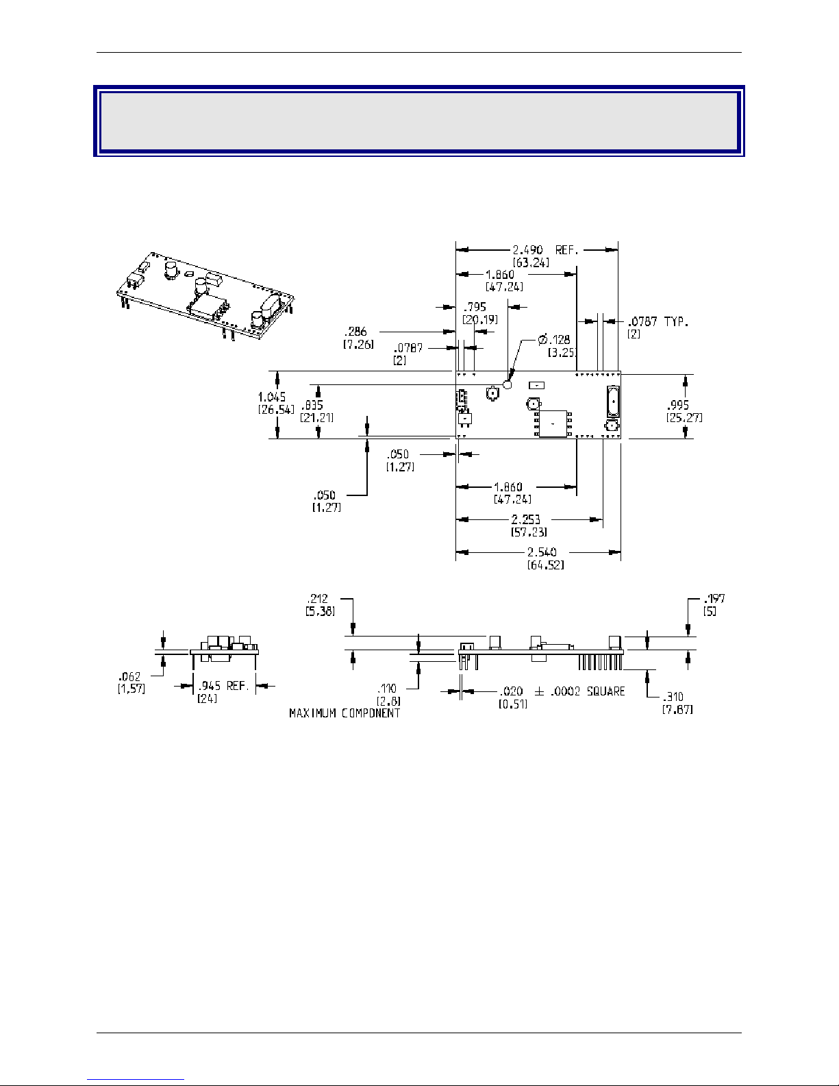
Physical Dimensions
Multi-Tech Systems, Inc. SocketModem MT5600SMI Developer’s Guide 8
Figure 2–1. Maximum Component Height
Page 9
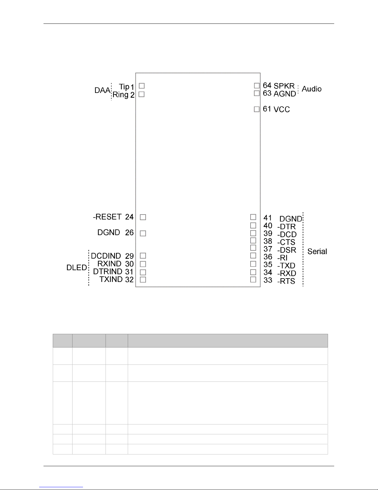
Chapter 2 – Mechanical Specifications
Serial Pin Configurations
The serial interface use an 16-pin interface to provide an on-board DAA with tip and ring connections,
audio circuit for call-progress monitoring and serial interface via logic level signals.
Figure 2–2. Serial SocketModems Pins
Available with or without LED Pins
Pin Descriptions for Serial SocketModem Devices
Pin#Signal
Name
1 Tip I/O
2 Ring I/O
24 –RESET I
26 DGND
29 DCDIND
30 RXIND
I/O
Type
Description
Tip Signal from Telco. Tip connection to the phone line (RJ11 Pin 3).
SocketModem is Tip/Ring is polarity insensitive.
Ring Signal from Telco. Ring connection to the phone line (RJ11 Pin 4).
SocketModem is Tip/Ring is polarity insensitive.
Modem Reset (with weak pull-up). The active low –RESET input resets the
SocketModem logic and returns the AT command set to the original factory
default values or to "stored values" in NVRAM. –RESET is tied to VCC
through a 400ms time constant circuit for "Power-on-Reset" functionality. The
modem is ready to accept commands within 6.5 seconds of power-on or reset.
Reset must be asserted for a minimum of 300 ns.
Ground
DCD LED. Output from 74AC05 with 1500 Ohms pull-up.
RX LED. Output from 74AC05 with 1500 Ohms pull-up.
Multi-Tech Systems, Inc. SocketModem MT5600SMI Developer’s Guide 9
Page 10

Chapter 2 – Mechanical Specifications
Pin#Signal
Name
31 DTRIND
32 TXIND
33 –RTS I
34 –RXD O
35 –TXD I
36 –RI O
37 –DSR O
38 –CTS O
39 –DCD O
40 –DTR I
41 DGND
61 VCC
63 AGND
64 SPKR
I/O
Type
Description
DTR LED. Output from 74AC05 with 1500 Ohms pull-up.
TX LED. Output from 74AC05 with 1500 Ohms pull-up.
Request to Send. RTS signal is used for hardware flow control.
Received Data. Used to send data received from the telephone line and also
modem responses to the DTE. Modem response take priority over incoming
data. When no data is transmitted, the signal is held in mark condition.
Transmit Data. The DTE uses this line to send data to the modem for
transmission over the telephone line or to transmit commands to the modem.
The DTE should hold this circuit in the mark state when no data is being
transmitted or during intervals between characters.
Ring Indicate. –RI output ON (low) indicates the presence of an ON segment
of a ring signal on the telephone line.
The modem will not go off-hook when –RI is active; the modem waits for –RI
to go inactive before going off-hook.
Data Set Ready. –DSR indicates modem status to the DTE. –DSR OFF
(high) indicates that the DTE is to disregard all signals appearing on the
interchange circuits except Ring Indicator (–RI). It reflects the status of the
local data set, and does not indicate an actual link with any remote data
equipment.
Clear To Send. –CTS is controlled by the modem to indicate whether or not
the modem is ready to transmit data. –CTS ON, indicates to the DTE that
signals presented on TXD will be transmitted to the telephone line. –CTS OFF
indicates to the DTE that it should not transfer data across the interface on
TXD.
Data Carrier Detect. –DCD output is ON (low) when a carrier is detected on
the telephone line or OFF (high) when carrier is not detected.
Data Terminal Ready (Active Low). The –DTR input is turned ON (low) by
the DTE when the DTE is ready to transmit or receive data. –DTR ON
prepares the modem to be connected to the telephone line, and, once
connected, maintains the connection. –DTR OFF places the modem in the
disconnect state.
Ground.
3.3V DC Power.
Analog Ground. Analog ground is tied common with DGND on the
SocketModem. To minimize potential ground noise issues, connect audio
circuit return to AGND.
Speaker Output. SPKR is a single ended-output. SPKR is tied directly to the
CODEC. One side of a differential AC output coupled through a 6.8K ohm
resistor and capacitor.
The call progress speaker interface signal is:
· Digital speaker output (DSPKOUT); output
DSPKOUT is a square wave output in data mode used for call progress or
carrier monitoring. This output can be optionally connected to a low-cost onboard speaker, e.g., a sounducer, or to an analog speaker circuit.
Multi-Tech Systems, Inc. SocketModem MT5600SMI Developer’s Guide 10
Page 11
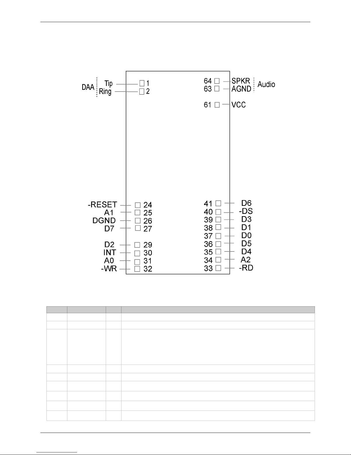
Chapter 2 – Mechanical Specifications
Parallel Pin Configurations
The parallel interface SocketModem uses a 22-pin interface to provide an on-board DAA with tip and ring
connections, audio circuit for call-progress monitoring, and parallel interface.
Figure 2–3. Parallel SocketModem Pins
Pin Descriptions for a Parallel SocketModem Device
Pin # Signal Name I/O Description
1 Tip I/O
2 Ring I/O
24 –RESET I
25 A1
26 DGND GND
27 D7 O
29 D2 O
30 INT O
31 A0 I
Multi-Tech Systems, Inc. SocketModem MT5600SMI Developer’s Guide 11
Telephone Line Interface – TIP
Telephone Line Interface – RING
Modem Reset (CMOS input with weak pull-up). The active low –RESET input
resets the SocketModem logic and returns the AT command set to the original
factory default values or to "stored values" in NVRAM.
The modem is ready to accept commands within 6.5 seconds of power-on or
reset. Reset must be asserted for a minimum of 300 ns.
Host Bus Address Line 1
Digital Ground
Host Bus Data Line 7
Host Bus Data Line 2
Host Bus Interrupt Line, Active High, Resets on Low
Host Bus Address Line 0
Page 12

Pin # Signal Name I/O Description
32 –WT I
33 –RD I
34 A2 I
35 D4 O
36 D5 O
37 D0 O
38 D1 O
39 D3 O
40 –CS I
41 D6 O
61 VCC PWR
63 AGND GND
Host Bus Write. When low, allows host to write to SocketModem.
Host Bus Read. When low, allows host to read from SocketModem.
Host Bus Address Line 2
Host Bus Data Line 4
Host Bus Data Line 5
Host Bus Data Line 0
Host Bus Data Line 1
Host Bus Data Line 3
Host Bus Chip Select; active low
Host Bus Data Line 6
3.3V or 5V Supply (depends upon model).
Analog Ground. This is tied common with DGND on the SocketModem. To
minimize potential ground noise issues, connect audio circuit return to AGND.
Chapter 2 – Mechanical Specifications
64 SPKR O
Speaker, Call Monitor
Multi-Tech Systems, Inc. SocketModem MT5600SMI Developer’s Guide 12
Page 13

Chapter 3 – Electrical Characteristics
Chapter 3 – Electrical Characteristics
Handling Precautions
All electronic devices should be handled with certain precautions to avoid damage due to the
accumulation of static charge. Although input protection circuitry has been incorporated into the devices
to minimize the effect of this static buildup, proper precautions should be taken to avoid exposure to
electrostatic discharge during handling and mounting.
I/O Electrical Characteristics
3.3V Serial SocketModem
3.3V DC Characteristics (TA = 0°C to 70°C; VDD = 3.3 V ± 0.3 V) VDDMAX = 3.6 V
Inputs
–DTR (40), –TXD (35), –RTS (33), –RESET (24)
Inputs
–DCD (39), –CTS (38), –DSR (37), –RI (36), –RXD (34)
2mA, Z INT = 120
Digital Input Capacitance 50pF
W
Input High
Min 2.0 V
Output High
Min 2.4 V
Input Low
Max 0.8 V
Output Low
Max 0.5 V
3.3V Parallel SocketModem
Electrical characteristics for Parallel SocketModem devices are presented below.
3.3V DC Characteristics (TA = 0°C to 70°C; VDD = 3.3 V ± 0.3 V)
Digital Inputs
–DS (40)
Digital Inputs (hysteresis input buffer)
A0 (31), A1 (25), A2 (34), –WR (32), –RD (33)
8mA Z
Digital Input/Output
DO (37), D1 (38), D2 (29), D3 (39), D4 (35), D5
(36), D6 (41), D7 (27)
2mA, Z
= 50W 2mA Z
INT
= 120 W
INT
= 120 W
INT
Input High
Min 2.0 V
Input High
Min 2.0 V
Input High
Min 2.0 V
Output High
Min 2.4 V
VDDMAX = 3.6 V
Input Low
Max 0.8 V
Input Low
Max 0.8 V
Input Low
Max 0.8 V
Output Low
Max 0.5 V
Digital Output
INT (30)
2mA, Z
Digital Input Capacitance 50pF
Multi-Tech Systems, Inc. SocketModem MT5600SMI Developer’s Guide 13
= 120 W
INT
Output High
Min 2.4 V
Output Low
Max 0.5 V
Page 14

Chapter 3 – Electrical Characteristics
5V Serial SocketModem
5 Vdc Characteristics (TA = 0 °C to 50 °C; VDD = 5 V ± 0.25 V) VDDMAX = 5.25 V
Digital Inputs
–DTR (40), –TXD (35), –RTS (33), –RESET (24)
Digital Outputs
–DCD (39), –CTS (38), –DSR (37), –RI (36), –RXD (34)
Digital Input Capacitance 5 PF
Input High
Min 3.5 V
Output High
Min 4 V
Input Low
Max .8 V
Output Low
Max 0.5 V
Current Drive
15 ma
5V Parallel SocketModem
5 Vdc Characteristics (TA = 0 °C to 50 °C; VDD = 5 V ± 0.25 V) VDDMAX = 5.25 V
Digital Inputs
–DS (40)
Digital Inputs (hysteresis input buffer)
A0 (31), A1 (25), –WR (32), –RD (33)
Digital Input / Output
DO (37), D1 (38), D2 (29), D3 (39), D4 (35), D5 (36),
D6 (41), D7 (27)
Digital Output
INT (30)
Input High
Min 2 V
Input High
Min 2 V
Input High
Min 2 V
Output High
Min 2.4 V
Input Low
Max .8 V
Input Low
Max .8 V
Input Low
Max .8 V
Output Low
Max 0.5 V
Current Drive
8 ma
Current Drive
8 ma
Digital Input Capacitance 5 PF
Operating Conditions
Parameter Symbol Limits Units
+3.3 V Configuration
Supply voltage (Pin 61 = +3.3 V) VDD +3.13 to +3.47 VDC
Operating ambient temperature T
+5 V Configuration
Supply voltage (Pin 61 = +5 V) VDD +4.75 to +5.25 VDC
Operating ambient temperature
A
T
A
0 to +70 °C
0 to +70 °C
Absolute Maximum Ratings
Parameter Symbol Limits Units
Supply voltage (Pin 61 = +3.3 V) VDD -0.5 to +4.0 VDC
Supply voltage (Pin 61 = +5 V)
Input voltage V
Voltage applied to outputs in high impedance (Off) state V
Storage temperature T
VDD -0.5 to +7.0 VDC
IN
OUT
STG
-0.5 to (VDD +0.5) VDC
+3.13 to +3.47
-40 to +80 °C
VDC
Multi-Tech Systems, Inc. SocketModem MT5600SMI Developer’s Guide 14
Page 15

Chapter 3 – Electrical Characteristics
Current and Power Requirements
Typ.
Mode
Normal Mode (Serial interface) 115 116 0.38 0.41
Normal Mode (Serial interface) 117 118 0.58 0.61
Normal Mode (Parallel interface) 117 118 0.58 0.61
Test conditions:
For Pin 61 = +5 V, VDD = +5 V for typical values; VDD = +5.25 V for maximum values.
For Pin 61 = +3.3 V, VDD = +3.3 V for typical values; VDD = +3.47 V for maximum values.
Current (mA)
+3.3 V Configuration (VDD = +3.3 V)
+5 V Configuration (VDD = +5 V)
Max.
Current (mA)
Typ.
Power (mW)
Max.
Power (mW)
Multi-Tech Systems, Inc. SocketModem MT5600SMI Developer’s Guide 15
Page 16

Chapter 3 – Electrical Characteristics
Parallel Host Bus Timing
Parallel Host Bus Timing Table
Symbol Parameter Min Max Units
t
AS
t
AH
t
CS
t
CH
t
RD
t
DD
t
DRH
Address Setup 5 - ns
Address Hold 10 - ns
Chip Select Setup 0 - ns
Chip Select Hold 10 - ns
RD Strobe Width 45 - ns
Read Data Delay - 25 ns
Read Data Hold 5 - ns
WRITE (See Notes)
t
AS
t
AH
t
CS
t
CH
t
WT
t
DS
t
DWH
Address Setup 5 - ns
Address Hold 15 - ns
Chip Select Setup 0 - ns
Chip Select Hold 10 - ns
WT Strobe Width 75 - ns
Write Data Setup (see Note 4) - 20 ns
Write Data Hold (see Note 5) 5 - ns
Notes:
1. When the host executes consecutive Rx FIFO reads, a minimum delay of 2 times the internal CPU
clock cycle plus 15 ns (85.86 ns at 28.224 MHz) is required from the falling edge of RD to the falling
edge of the next Host Rx FIFO RD clock.
2. When the host executes consecutive Tx FIFO writes, a minimum delay of 2 times the internal CPU
clock cycle plus 15 ns (85.86 ns at 28.224 MHz) is required from the falling edge of WT to the
falling edge of the next Host Tx FIFO WT clock.
t
3.
RD' tWT
4.tDS is measured from the point at which both CS and WT are active.
t
5
.
DWH is measured from the point at which either CS and WT become active.
t
=
CYC
+ 15 ns.
6. Clock Frequency = 28.224 MHz clock.
READ (See Notes)
Multi-Tech Systems, Inc. SocketModem MT5600SMI Developer’s Guide 16
Page 17
Parallel Host Bus - Read
Chapter 3 – Electrical Characteristics
Parallel Host Bus - Write
Multi-Tech Systems, Inc. SocketModem MT5600SMI Developer’s Guide 17
Page 18

Chapter 4 – SocketModem Parallel Interface – A Programmer's Description
Chapter 4 – SocketModem Parallel
Interface – A Programmer’s
Description
SocketModem Parallel Interface
The modem supports a 16550A interface in parallel interface versions. The 16550A interface can operate
in FIFO mode or non-FIFO mode. Non-FIFO mode is the same as the 16450 interface operation. FIFO
mode’s unique operations are described in this chapter.
Overview
The modem emulates the 16450/16550A interface and includes both a 16-byte receiver data first-in firstout buffer (RX FIFO) and a 16-byte transmit data first-in first-out buffer (TX FIFO).
FIFO Mode Selected
When FIFO mode is selected in the FIFO Control Register (FCR0 = 1), both FIFOs are operative.
Furthermore, when FIFO mode is selected, DMA operation of the FIFO can also be selected (FCR3 = 1).
FIFO Mode Not Selected
When FIFO mode is not selected, operation is restricted to a 16450 interface operation.
Receive Data
Received Data is read by the host from the Receiver Buffer (RX Buffer). The RX Buffer corresponds to
the Receiver Buffer Register in a 16550A device. In FIFO mode, the RX FIFO operates transparently
behind the RX Buffer. Interface operation is described with reference to the RX Buffer in FIFO and nonFIFO modes.
Transmit Data
Transmit Data is loaded by the host into the Transmit Buffer (TX Buffer). The TX Buffer corresponds to
the Transmit Holding Register in a 16550A device. In FIFO mode, the TX FIFO operates transparently
behind the TX Buffer. Interface operation is described with reference to the TX Buffer in both FIFO and
non-FIFO modes.
Note
The parallel interface registers and the corresponding bit assignments are shown in Table 4–1.
Multi-Tech Systems, Inc. SocketModem MT5600SMI Developer’s Guide 18
Page 19

Chapter 4 – SocketModem Parallel Interface – A Programmer's Description
Table 4–1. Parallel Interface Registers
Register
No.
7 Scratch Register (SCR) Scratch Register
6 Modem Status Register
5 Line Status Register
4 Modem Control
3 Line Control Register
2 Interrupt Identify
2 FIFO Control Register
1
(DLAB = 0)
0
(DLAB = 0)
0
(DLAB = 0)
1
(DLAB = 1)
0
(DLAB = 1)
Register
Name
(MSR)
(LSR)
Register (MCR)
(LCR)
Register (IIR)
(Read Only)
(FCR)
(Write Only)
Interrupt Enable
Register (ER)
Transmitter Buffer
Register
(THR)
Receiver Buffer
Register (RBR)
Divisor Latch MSB
Register (DLM)
Divisor Latch LSB
Register (DLL)
7 6 5 4 3 2 1 0
Data
Carrier
Detect
(DCD)
RX
FIFO
Error
0 0 0 Local
Divisor
Latch
Access Bit
(DLAB)
FIFOs
Enabled
Receiver
Trigger
MSB
0 0 0 0 Enable
Ring
Indicator
(RI)
Transmitter
Empty
(TEMT)
Set
Break
FIFOs
Enabled
Receiver
Trigger
LSB
Data Set
Ready
(DSR)
Transmitter
Buffer
Register
Empty
(THRE)
Stick
Parity
Reserved Reserved DMA
Transmitter FIFO Buffer Register (Write Only)
Send CTS)
Loopback
0 0 Pending
Receiver FIFO Buffer Register (Read Only)
BIT No.
Clear to
Break
Interrupt
(BI)
Even
Parity
Select
(EPS)
Divisor Latch MSB
Divisor Latch LSB
Delta Data
Carrier
Detect
(DDCD)
Framing
Error
(FE)
Out 2 Out 1 Request
Parity
Enable
(PEN)
Interrupt ID
Bit 2
Mode
Select
Modem
Status
Interrupt
(EDSSI)
Trailing
dge of Ring
Indicator
(TERI)
Parity
Error
(PE)
Number
of Stop
Bits
(STB)
Pending
Interrupt ID
Bit 1
TX FIFO
Reset
Enable
Receiver
Line Status
Interrupt
(ELSI)
Delta Data
Set Ready
Interrupt ID
Transmitter
(DDSR)
Overrun
Error
(OE)
to Send
(RTS)
Word
Length
Select
Bit 1
(WLS1)
Pending
Bit 0
RX FIFO
Reset
Enable
Holding
Register
Empty
Interrupt
(ETBEI)
Delta Clear
to Send
(DCTS)
Receiver
Data
Ready
(DR)
Data
Terminal
Ready
(DTR)
Word Length
Select
Bit 0
(WLSO)
“0” if
Interrupt
Pending
FIFO
Enable
Enable
Received
Data
Available
Interrupt
(ERBFI)
Multi-Tech Systems, Inc. SocketModem MT5600SMI Developer’s Guide 19
Page 20

Chapter 4 – SocketModem Parallel Interface – A Programmer's Description
Register Signal Definitions
IER – Interrupt Enable Register (Addr = 1, DLAB = 0)
The IER enables five types of interrupts that can separately assert the HINT output signal (Table 4–
2.). A selected interrupt can be enabled by setting the corresponding enable bit to a 1, or disabled by
setting the corresponding enable bit to a 0. Disabling an interrupt in the IER prohibits setting the
corresponding indication in the IIR and assertion of HINT. Disabling all interrupts (resetting IER0 –
IER3 to a 0) inhibits setting of any Interrupt Identifier Register (IIR) bits and inhibits assertion of the
HINT output. All other system functions operate normally, including the setting of the Line Status
Register (LSR) and the Modem Status Register (MSR).
The IER enables five types of interrupts that can separately assert the HINT output signal. A selected
interrupt can be enabled by setting the corresponding enable bit to a 1, or disabled by setting the
corresponding enable bit to a 0. Disabling an interrupt in the IER prohibits setting the corresponding
indication in the IIR and assertion of HINT. Disabling all interrupts (resetting IER0 - IER3 to a 0)
inhibits setting of any Interrupt Identifier Register (IIR) bits and inhibits assertion of the HINT output.
All other system functions operate normally, including the setting of the Line Status Register (LSR)
and the Modem Status Register (MSR).
Bits 7-4 Not used.
Always 0.
Bit 3 Enable Modem Status Interrupt (EDSSI).
This bit, when a 1, enables assertion of the HINT output whenever the Delta CTS
(MSR0), Delta DSR (MSR1), Delta TER (MSR2), or Delta DCD (MSR3) bit in the
Modem Status Register (MSR) is a 1. This bit, when a 0, disables assertion of
HINT due to setting of any of these four MSR bits.
Bit 2 Enable Receiver Line Status Interrupt (ELSI).
This bit, when a 1, enables assertion of the HINT output whenever the Overrun
Error (LSR1), Parity Error (LSR2), Framing Error (LSR3), or Break Interrupt
(LSR4) receiver status bit in the Line Status Register (LSR) changes state. This
bit, when a 0, disables assertion of HINT due to change of the receiver LSR bits
1-4.
Bit 1 Enable Transmitter Holding Register Empty Interrupt (ETBEI).
This bit, when a 1, enables assertion of the HINT output when the Transmitter
Empty bit in the Line Status Register (LSR5) is a 1. This bit, when a 0, disables
assertion of HINT due to LSR5.
Bit 0 Enable Receiver Data Available Interrupt (ERBFI) and Character Timeout in
FIFO Mode.
This bit, when a 1, enables assertion of the HINT output when the Receiver Data
Ready bit in the Line Status Register (LSR0) is a1 or character timeout occurs in
the FIFO mode. This bit, when a 0, disables assertion of HINT due to the LSR0
or character timeout.
Multi-Tech Systems, Inc. SocketModem MT5600SMI Developer’s Guide 20
Page 21

Chapter 4 – SocketModem Parallel Interface – A Programmer's Description
FCR – FIFO Control Register (Addr = 2, Write Only)
The FCR is a write-only register used to enable FIFO mode, clear the RX FIFO and TX FIFO, enable
DMA mode, and set the RX FIFO trigger level.
Bits 7-6 RX FIFO Trigger Level
FCR7 and FCR6 set the trigger level for the RX FIFO (Receiver Data Available) interrupt.
FCR7 FCR6 RX FIFO Trigger Level (Bytes)
0001
0104
1008
1114
Bits 5-4
Bit 3 DMA Mode Select
Not used
When FIFO mode is selected (FCR0 = 1), FCR3 selects non-DMA operation (FCR3 = 0) or DMA
operation (FCR3 = 1). When FIFO mode is not selected (FCR0 = 0), this bit is not used (the
modem operates in non-DMA mode in 16450 operation).
DMA Operation in FIFO Mode
RXRDY will be asserted with the number of characters in the RX FIFO us equal to or greater
than the value in the RX FIFO Trigger Level (IIR0-IIR3 = 4h) or the received character
timeout (IIRO-IIR3 = Ch) has occurred. RXTDY will go inactive when there are no more
characters in the RX FIFO.
TXRDY will be asserted when there are one or more empty (unfilled) locations in the TX
FIFO. TXRDY will go inactive when the TX FIFO is completely full.
Non-DMA Operation in FIFO Mode
RXRDY will be asserted when there are one or more characters in the RX FIFO. RXRDY will
go inactive when there are no more characters in the RX FIFO.
TXRDY will be asserted when there are no characters in the TX FIFO. TXRDY will go
inactive when the character is loaded into the TX FIFO Buffer.
Bit 2 TX FIFO Reset
When FCR2 is a 1, all bytes in the TX FIFO are cleared. This bit is cleared automatically by the
modem.
Bit 1 RX FIFO Reset
When FCR1 is a 1, all bytes in the RX FIFO are cleared. This bit is cleared automatically by the
modem.
Bit 0 FIFO Enable
When FCR0 is a 0, 16450 mode is selected and all bits are cleared in both FIFOs. When FCR0
is a 1, FIFO mode (16550A) is selected and both FIFOs are enabled. FCR0 must be a 1 when
other bits in the FCR are written or they will not be acted upon.
Multi-Tech Systems, Inc. SocketModem MT5600SMI Developer’s Guide 21
Page 22

Chapter 4 – SocketModem Parallel Interface – A Programmer's Description
IIR – Interrupt Identifier Register (Addr = 2)
The Interrupt Identifier Register (IIR) identifies the existence and type of up to five prioritized pending
interrupts. Four priority levels are set to assist interrupt processing in the host. The four levels, in
order of decreasing priority, are Highest: Receiver Line Status, 2: Receiver Data Available or
Receiver Character Timeout. 3: TX Buffer Empty, and 4: Modem Status.
When the IIR is accessed, the modem freezes all interrupts and indicates the highest priority interrupt
pending to the host. Any change occurring in interrupt conditions are not indicated until this access is
complete.
Bits 7-6 FIFO Mode
These two bits copy FCR0.
Bits 5-4 Not Used
Always 0.
Bits 3-1 Highest Priority Pending Interrupt
These three bits identify the highest priority pending interrupt (Table 4-2). Bit 3 is applicable
only when FIFO mode is selected; otherwise, bit 3 is a 0.
Bit 0 Interrupt Pending
When this bit is a 0, an interrupt is pending; IIR bits 1-3 can be used to determine the source
of the interrupt. When this bit is a 1, an interrupt is not pending.
Table 4–2. Interrupt Sources and Reset Control
Interrupt Identification Register Interrupt Set and Reset Functions
Bit 3
(Note 1)
Bit 2 Bit 1 Bit 0 Priority
Level
Interrupt Type Interrupt Source Interrupt Reset
Control
0 0 0 1 — None None —
0 1 1 0 Highest Receiver Line
Status
0 1 0 0 2 Received Data
Available
1 1 0 0 2 Character Timeout
Indication
0 0 1 0 3 TX Buffer Empty TX Buffer Empty Reading the IIR
0 0 0 0 4 Modem Status Delta CTS (DCTS) (MSR0),
1
Overrun Error (OE) (LSR1),
Parity Error (PE) (LSR2),
Framing Error (FE) (LSR3),
or Break Interrupt (BI) (LSR4)
Received Data Available
(LSR0)
or RX FIFO Trigger Level
(FCR6-FCR7)
Reached
The RX FIFO contains at
least 1 character and no
characters have been
removed from or input to the
RX FIFO during the last 4
character times.
Delta DSR (DDST) (MSR1),
Trailing Edge Ring Indicator
(TERI) (MSR3), or Delta
DCD (DCD) (MSR4)
1
Reading the LSR
Reading the RX
Buffer or the RX
FIFO drops
below the
Trigger Level
Reading the RX
Buffer
or writing to the
TX Buffer
Reading the
MSR
Notes:
1. FIFO Mode only.
Multi-Tech Systems, Inc. SocketModem MT5600SMI Developer’s Guide 22
Page 23

Chapter 4 – SocketModem Parallel Interface – A Programmer's Description
LCR – Line Control Register (Addr = 3)
The Line Control Register (LCR) specifies the format of the asynchronous data communications
exchange.
Bit 7 Divisor Latch Access Bit (DLAB)
This bit must be set to a 1 to access the Divisor Latch Registers during a read or write operation.
It must be reset to a 0 to access the Receiver Buffer, the Transmitter Buffer, or the Interrupt
Enable Register.
Bit 6 Set Break
When bit 6 is a 1, the Transmit data is forced to the break condition, i.e., space (0) is sent. When
bit 6 is a 0, break is not sent. The Set Break bit acts only on the Transmit data and has no effect
on the serial in logic.
Bit 5 Stick Parity
When Parity is enabled (LCR3 = 1) and stick parity is selected (LCR5 = 1), the parity bit is
transmitted and checked by the receiver as a 0 if even parity is selected (LCR4 – 1) or a 1 if odd
parity is selected (LCR4 = 0). When the stick parity is not selected (LCR3 = 0), parity is transmit
and checked as determined by the LCR3 and LCR4 bits.
Bit 4 Even Parity Select (EPS)
When parity is enabled (LCR3 = 1) and stick parity is not selected (LCR5 = 0), the number of 1s
transmitted or checked by the receiver in the data word bits and parity bit is either even (LCR4 =
1) or odd (LCR4 = 0).
Bit 3 Enable Parity (PEN)
When bit 3 is a 1, a parity bit is generated in the serial out (transmit) data stream and checked in
the serial in (receive) data stream as determined by the LCR4 and LCR5 bits. The parity bit is
located between the last data bit and the first stop bit.
Bit 2 Number of Stop GBITS (STB)
This bit specifies the number of stop bits in each serial out character. If bit 2 is a 0, one stop bit is
generated regardless of word length. If bit 2 is a 1 and 5-bit word length is selected, one and
one-half stop bits are generated. If bit 2 is a 1 and 6-, 7-, or 8-bit word length is selected, two
stop bits are generated. The serial in logic checks the first stop bit only, regardless of the number
of stop bits selected.
Bit 1-0 Word Length Select (WLS0 and WLS1)
These two bits specify the number of bits in each serial in or serial out character. The encoding
of bits 0 and 1 is:
Bit 1 Bit 0 Word Length
0 0 5 Bits (Not supported)
0 1 6 Bits (Not supported)
10 7 Bits
11 8 Bits
Multi-Tech Systems, Inc. SocketModem MT5600SMI Developer’s Guide 23
Page 24

Chapter 4 – SocketModem Parallel Interface – A Programmer's Description
MCR – Modem Control Register (Addr = 4)
The Modem Control Register (MCR) controls the interface with modem or data set.
Bit 7-5 Not used
Always 0
Bit 4 Local Loopback
When this bit is set to a 1, the diagnostic mode is selected and the following occurs:
1. Data written to the Transmit Buffer is looped back to the Receiver Buffer.
2. The DTS (MCR0), RTS (MCR1), Out1 (MCR2), and Out2 (MCR3) modem control register
bits are internally connected to the DSR (MSR5), CTS (MSR4), RI (MSR6), and DCD
(MSR7) modem status register bits, respectively.
Bit 3 Output 2
When this bit is a 1, HINT is enabled. When this bit is a 0, HINT is in the high impedance state.
Bit 2 Output 1
This bit is used in local loopback (see MCR4).
Bit 1 Request to Send (RTS)
This bit controls the Request to Send (RTS) function. When this bit is a 1, RTS is on. When this
bit is a 0, RTS is off.
Bit 0 Data Terminal Ready (DTR)
This bit controls the Data Terminal Ready (DTR) function. When this bit is a 1, DTR is on. When
this bit is a 0, DTR is off.
Multi-Tech Systems, Inc. SocketModem MT5600SMI Developer’s Guide 24
Page 25

Chapter 4 – SocketModem Parallel Interface – A Programmer's Description
LSR – Line Status Register (Addr = 5)
This 8-bit register provides status information to the host concerning data transfer.
Bit 7 RX FIFO Error
In the 16450 mode, this bit is not used and is always 0.
In the FIFO mode, this bit is set if there are one or more characters in the RX FIFO with parity
error, framing error, or break indication detected. This bit is reset to a 0 when the host reads the
LSR and note of the above conditions exist in the RX FIFO.
Bit 6 Transmitter Empty (TEMT)
This bit is set to a 1 whenever the TX Buffer (THR) and equivalent of the Transmitter Shift
Register (TRS) are both empty. It is reset to a 0 whenever either the THR or the equivalent of the
TSR contains a character.
In the FIFO mode, this bit is set to a 1 whenever the TX FIFO and the equivalent of the TSR are
both empty
Bit 5 Transmitter Holding Register Empty (THRE) [TX Buffer Empty]
This bit, when set, indicates that the TX Buffer is empty and the modem can accept a new
character for transmission. In addition, this bit causes the modem to issue an interrupt to the host
when the Transmit Holding Register Empty Interrupt Enable bit (IIR1) is set to 1. The THRE bit is
set to a 1 when a character is transferred from the TX Buffer. The bit is reset to 0 when a byte is
written into the TX Buffer by the host.
In the FIFO mode, this bit is set when the TX FIFO is empty; it is cleared when at lease one byte
is in the TX FIFO.
Bit 4 Break Interrupt (BI)
This bit is set to a 1 whenever the received data input is a space (logic 0) for longer than two full
word lengths plus 3 bits. The BI is reset when the host reads the LSR.
Bit 3 Framing Error (FE)
This bit indicates that the received character did not have a valid stop bit. The FE bit is set to a 1
whenever the stop bit following the last data bit or parity bit is detected as a logic o (space). The
FE bit is reset to a 0 when the host reads the LSR.
In the FIFO mode, the error indication is associated with the particular character in the FIFO it
applies to. The FE bit set to a 1 when this character is loaded into the RX Buffer.
Bit 2 Parity Error (PE)
This bit indicates that the received data character in the RX Buffer does not have the correct
even or odd parity, as selected by the Even Parity Select bit (LCR4) and the Stick Parity bit
(LCR5). The PE bit is reset to a 0 when the host reads the LSR.
In the FIFO mode, the error indication is associated with the particular character in the FIFO it
applies to. The PE bit set to a 1 when this character is loaded into the RX Buffer.
Bit 1 Overrun Error (OE)
This bit is set to a 1 whenever received data is loaded into the RX Buffer before the host has
read the previous data from the RX Buffer. The OE is reset to a 0 when the host reads the LSR.
In the FIFO mode, if data continues to fill beyond the trigger level, an overrun condition will occur
only if the RX FIFO is full and the next character has been completely received.
Bit 0 Receiver Data Ready (DR)
This bit is set to a 1 whenever a complete incoming character has been received and transferred
into the RX Buffer. The DR bit is reset to a 0 when the host reads the RX Buffer.
In the FIFO mode, the DR bit is set when the number of received data bytes in the RX FIFO
equals or exceeds the trigger level specified in the FCR0-FCR1.
Multi-Tech Systems, Inc. SocketModem MT5600SMI Developer’s Guide 25
Page 26

Chapter 4 – SocketModem Parallel Interface – A Programmer's Description
MSR – Modem Status Register (Addr = 6)
The Modem Status Register (MSR) reports current state and change information of the modem. Bits
4-7 supply current state, and bits 0-3 supply change information. The change bits are set to a 1
whenever a control input form the modem changes state from the last MSR read by the host. Bits 0-3
are reset to 0 when the host reads the MSR or upon reset.
Whenever bits 0, 1, 2, or 3 are set to a 1, a Modem Status Interrupt (IIR0-IIR3 = 0) is generated.
Bit 7 Data Carrier Detect (DCD)
This bit indicates the logic state of the DCH# (RLSD#) output. If Loopback is selected (MCR4 =
1), this bit reflects the state of the Out2 bit in the MCR (MCR3).
Bit 6 Ring Indicator (RI)
This bit indicates the logic state of the RI# output. If Loopback is selected (MCR4 = 1), this bit
reflects the state of the Out1 bit in the MCR (MCR2).
Bit 5 Data Set Ready (DSR)
This bit indicates the logic state of the DSR# output. If Loopback is selected (MCR4 = 1), this bit
reflects the state of the DTR in the MCR (MCR0).
Bit 4 Clear to Send (CTS)
This bit indicates the logic state of the CTS# output. If Loopback is selected (MCR4 = 1), this bit
reflects the state of the RTS bit in the MCR (MCR1).
Bit 3 Delta Data Carrier Detect (DDCD)
This bit is set to a 1 when the DCD bit changes state since the host last read the MSR.
Bit 2 Trailing Edge of Ring Indicator (TERI)
This bit is set to a 1 when the RI bit changes from a 1 to a 0 state since the host last read the
MSR.
Bit 1 Delta Data Set Ready (DDSR)
This bit is set to a 1 when the DSR bit has changed since the host last read the MSR.
Bit 0 Delta Clear to Send (DCTS)
This bit is set to a 1 when the CTS bit has changed since the MSR the host last read the MSR.
RBX – RX Buffer (Receiver Buffer Register) (Addr = 0,
DLAB = 0)
The RX Buffer (RBR) is a read-only register at location 0 (with DLAB = 0). Bit 0 is the least significant
bit of the data and is the first bit received.
THR – TX Buffer (Transmitter Holding Register) (Addr = 0,
DLAB = 0)
The TX Buffer (THR) is a write-only register at address 0 when DLAB = 0. Bit 0 is the least significant
bit and the first bit sent.
Divisor Registers (Addr = 0 and 1, DLAB = 1)
The Divisor Latch LS (least significant byte) and Divisor Latch MS (most significant byte) are two
read-write registers at locations 0 and 1 when DLAB = 1, respectively.
The baud rate is selected by loading each divisor latch with the appropriate hex value.
Programmable values corresponding to the desired baud rate are listed in Table 4-3.
Multi-Tech Systems, Inc. SocketModem MT5600SMI Developer’s Guide 26
Page 27

Chapter 4 – SocketModem Parallel Interface – A Programmer's Description
SCR – Scratch Register (Addr = 7)
The Scratchpad Register is a read-write register at location 7. This register is not used by the modem
and can be used by the host for temporary storage.
Divisor Latch (Hex)
MS LS Divisor (Decimal) Baud Rate
06 00 1536 75
04 17 1047 110
03 00 768 150
01 80 384 300
00 C0 192 600
00 60 96 1200
00 30 48 2400
00 18 24 4800
00 0C 12 9600
00 06 6 19200
00 04 4 28800
00 03 3 38400
00 02 2 57600
00 01 1 115600
00 00 NA 230400
Table 4–3. Programmable Baud Rates
Multi-Tech Systems, Inc. SocketModem MT5600SMI Developer’s Guide 27
Page 28

Chapter 4 – SocketModem Parallel Interface – A Programmer's Description
Receiver FIFO Interrupt Operation
Receiver Data Available Interrupt
When the FIFO mode is enabled (FCR0 = 1) and receiver interrupt (RX Data Available) is enabled
(IER0 = 1), receiver interrupt operation is as follows:
1.
The Receiver Data Available Flag (LSR0) is set as soon as a received data character is
available in the RX FIFO. LSR0 is cleared when RX FIFO is empty.
The Receiver Data Available Interrupt code (IIR0-IIR4 = 4h) is set whenever the number of
2.
received data bytes in the RX FIFO reaches the trigger level specified by FCR6-FCR7 bits. It
is cleared whenever the number of received data bytes in the RX FIFO drops below the
trigger level specified by FCR6-FCR7 bits.
The HINT interrupt is asserted whenever the number of received data bytes in the RX FIFO
3.
reaches the trigger level specified by FCR6-FCR7 bits. HINT interrupt is de-asserted when
the number of received data bytes in the RX FIFO drops below the trigger level specified by
FCR6-FCR7 bits.
Receiver Character Timeout Interrupts
When the FIFO mode is enabled (FCR0 = 1) and receiver interrupt (Receiver Data Available) is
enabled (IER0 = 1), receiver character timeout interrupt operation is as follows:
A Receiver character timeout interrupt code (IIR0-IIR3 = Ch) is set if at least one received
1.
character is in the RX FIFO, the most recent received serial character was longer than four
continuous character times ago (if 2 stop bits are specified, the second stop bit is included in
this time period), and the most recent host read of the RX FIFO was longer than four
continuous character times ago.
Transmitter FIFO Interrupt Operation
Transmitter Empty Interrupt
When the FIFO mode is enabled (FCR0 = 1) and transmitter interrupt (TX Buffer Empty) is enabled
(IER0 =1), transmitter interrupt operation is as follows:
1.
The TX Buffer Empty interrupt code (IIR0-IIR3 = 2h) will occur when the TX Buffer is empty. It
is cleared when the TX Buffer is written to (1 to 16 characters) or the IIR is read.
The TX Buffer Empty indications will be delayed 1 character time minus the last stop bit time
2.
whenever the following occur: THRE = 1 and there have not been at least two bytes at the
same time in the TX FIFO Buffer since the last setting of THRE was set. The first transmitter
interrupt after setting FCR0 will be immediate.
Multi-Tech Systems, Inc. SocketModem MT5600SMI Developer’s Guide 28
Page 29

Chapter 5 – AT Commands, S-Registers, and Result Codes
Chapter 5 – AT Commands, S-
Registers, and Result Codes
Introduction
The AT commands are used to control the operation of your modem. They are called AT commands
because the characters AT must precede each command to get the ATtention of the modem.
AT commands can be issued only when the modem is in command mode or online command mode. The
modem is in command mode whenever it is not connected to another modem. The modem is in data
mode whenever it is connected to another modem and ready to exchange data. Online command mode is
a temporary state in which you can issue commands to the modem while connected to another modem.
To put the modem into online command mode from data mode, you must issue an escape sequence
(+++) followed immediately by the AT characters and the command, e.g., +++ to hang up the modem. To
return to data mode from online command mode, you must issue the command ATO.
To send AT commands to the modem you must use a communications program, such as the
HyperTerminal applet in Windows 98/95 and NT 4.0, or some other available terminal program. You can
issue commands to the modem either directly, by typing them in the terminal window of the
communications program, or indirectly, by configuring the operating system or communications program
to send the commands automatically. Fortunately, communications programs make daily operation of
modems effortless by hiding the commands from the user. Most users, therefore, need to use AT
commands only when reconfiguring the modem, e.g., to turn autoanswer on or off.
The format for entering an AT command is ATXn, where X is the command, and n is the specific value for
the command, sometimes called the command parameter. The value is always a number. If the value is
zero, you can omit it from the command; thus, AT&W is equivalent to AT&W0. Most commands have a
default value, which is the value that is set at the factory. The default values are shown in the “AT
Command Summary” (See below).
You must press ENTER (depending on the terminal program it could be some other key) to send the
command to the modem. Any time the modem receives a command, it sends a response known as a
result code. The most common result codes are OK, ERROR, and the CONNECT messages that the
modem sends to the computer when it is connecting to another modem. See “Result Codes” at the end of
this chapter for a table of valid result codes.
You can issue several commands in one line, in what is called a command string. The command string
begins with AT and ends when you press ENTER. Spaces to separate the commands are optional; the
command interpreter ignores them. The most familiar command string is the initialization string, which is
used to configure the modem when it is turned on or reset, or when your communications software calls
another modem.
Multi-Tech Systems, Inc. SocketModem MT5600SMI Developer’s Guide 29
Page 30

Chapter 5 – AT Commands, S-Registers, and Result Codes
Data Commands
The modem will respond to the commands detailed below. Parameters applicable to each command are
listed with the command description.
Generic Modem Control Commands
Command: Z Soft Reset and Restore Profile
Description: Causes the modem to perform a soft reset and restore (recall) the
configuration profile. If no value is specified, zero is assumed.
Default: None
Values: Number corresponding to the selected profile:
Z0 Soft reset and restore stored profile 0.
Z1 Soft reset and restores stored profile 1.
Result Codes: OK
Otherwise ERROR
Command: +FCLASS Select Active Service Class
Description: Selects the active service class (mode).
Default: 0
Defined Values: +FCLASS=0 Select Data Mode (Section 3) (Default).
+FCLASS=1 Select Facsimile Class 1 Mode.
+FCLASS=1.0 Select Facsimile Class 1.0 Mode.
+FCLASS=8 Select Voice Mode.
+FCLASS=10 Reserved.
Result Codes: OK
Otherwise ERROR
Report Commands: +FCLASS? Reports Current or Selected Values
+FCLASS=? Reports Range of Parameters
Command: +VCID Caller ID (CID)
Description: Controls the reporting and presentation of data associated with the Caller
ID services in the Incoming Call Line ID (ICLID) data format for the next
call. (U.S. only)
Default: 0
Defined Values: +VCID0 Disable Caller ID reporting.
+VCID1 Enables Caller ID with formatted presentation to the DTE. The
modem presents the data items in a <Tag><Value> pair
format. The expected pairs are date, time, name, and caller
code (telephone number).
+VCID2 Enables Caller ID with unformatted presentation to the DTE.
Report Commands: +VCID? Reports the Mode
+VCID=? Reports Range of Parameters
Command: +VRID Report Retrieved Caller ID (CID)
Description: Reports the data associated with the Caller ID services in the Incoming
Caller Line (ICLID) data format for the last received call. U.S. only
Default: None
Defined Values: +VRID0 Reports Caller ID with formatted presentation to the DTE. The
modem presents the data items in a <Tag><Value> pair
format. The expected pairs are date, time, name, and caller
code (telephone number).
+VRID1 Reports Caller ID with unformatted presentation to the DTE.
Report Commands: +VRID? Reports the Mode
Multi-Tech Systems, Inc. SocketModem MT5600SMI Developer’s Guide 30
Page 31

Chapter 5 – AT Commands, S-Registers, and Result Codes
Command: \N Operating Mode - Error Correction
Description: Controls the preferred error-correcting mode to be negotiated in a
subsequent data connection. This command is affected by the OEM
firmware configuration.
Default: 5
Defined Values: \N0 Selects normal speed buffered mode (disables error-correction
mode). (Forces &Q6.)
\N1 Serial interface selected: Selects direct mode and is equivalent to
&M0, Q0 mode of operation. (Forces &Q0.) Parallel interface
selected: Same as \N0.
\N2 Selects reliable (error-correction) mode. The modem will first attempt
a LAPM connection and then an MNP connection. Failure to make a
reliable connection results in the modem hanging up. (Forces &Q5,
S36=4, and S48=7.)
\N3 Selects auto-reliable mode. This operates the same as \N2 except
failure to make a reliable connection results in the modem falling
back to the speed buffered normal mode. (Forces &Q5, S36=7, and
S48=7.)
\N4 Selects LAPM error-correction mode. Failure to make an LAPM
error-correction connection results in the modem hanging up.
(Forces &Q5 and S48=0.) Note: The -K1 command can override the
\N4 command.
\N5 Selects MNP error-correction mode. Failure to make an MNP error-
correction connection results in the modem hanging up. (Forces
&Q5, S36=4, and S48=128.)
Result Codes: OK
Otherwise ERROR
Command I Identification
Description: Causes the modem to reports the requested result according to the
command parameter.
Default: 4
Defined Values: I0 Reports product code (e.g., 56000).
I1 Reports the least significant byte of the stored checksum (e.g.,
12AB).
I2 Checks ROM and verifies the checksum. Reports OK or ERROR.
I3 Reports ROM Code Revision-Modulation (e.g., 2109-V90).
I4 Reports OEM defined identifier string in binary format (default) or
ASCII formats. (e.g.: a007040284C6002F bC60000000
r1005111151012000 3000111170000000).
I5 Reports Country Code parameter (see +GCI).
I6 Reports modem data pump model and internal code revision.
Result Codes: OK
Otherwise ERROR
Command: +GMI Request Manufacturer Identification
Description: Causes the modem to report the modem product manufacturer.
Typical Response: +GMI: Multi-Tech
OK
Multi-Tech Systems, Inc. SocketModem MT5600SMI Developer’s Guide 31
Page 32

Chapter 5 – AT Commands, S-Registers, and Result Codes
Command +GMM Request Model Identification
Description: Causes the modem to report the modem product.
Typical Response: +GMM: V92
Command: +GMR Request Revision Identification
Description: Causes the modem to report the modem version, revision level, or date.
This is the same as the I3 command.
Typical Response: +GMR: P2109-V90
OK
Command: +GCAP Request Complete Capabilities List
Description: This extended-format command causes the modem to transmit one or
more lines of information text listing additional capabilities command
+<name>s, which is intended to permit the user to identify the overall
capabilities of the modem. In particular, if the modem implements a
particular modem control standard that uses Extended Syntax Commands,
and if that modem control standard includes command(s) that indicate
general capabilities, the +<names>(s) of those commands will be reported
to the modem in response to a +GCAP command.
Example Responses: +GCAP: +FCLASS, +MS, +ES, +DS, for a data modem that supports all
capabilities listed. Where:
+MS +M commands (Modulation Control: +MS and +MR commands)
+ES +E commands (Error Control: +ES, +EB, +ER, +EFCS, +ETBM)
+DS +D commands (Data Compression: +DS and +DR). Manual
Command: +GCI Country of Installation
Description: This extended syntax command selects and indicates the country of
installation for the modem. This parameter selects the settings for any
operational parameters that need to be adjusted for national regulations or
telephone networks. The chapter Setting Country Codes for more
information.
Default: If the modem is specified for use in only one country, that country code is
the default. Otherwise, the default is defined by the OEM. Factory default is
B5 (United States).
Report Commands: +GCI? Reports the current country code.
+GCI=? Displays the list of available country codes.
Command: &F Restore Factory Configuration (Profile)
Description: The modem loads the factory default configuration (profile). The factory
defaults are identified for each command and in the S-Parameter
descriptions. A configuration (profile) consists of a subset of S-Parameters.
Default: None
Values: &F0 Restore factory configuration 0.
&F Restore factory configuration 1.
Result Codes: OK
ERROR if the modem is connected.
Multi-Tech Systems, Inc. SocketModem MT5600SMI Developer’s Guide 32
Page 33

Chapter 5 – AT Commands, S-Registers, and Result Codes
Command: &T Local Analog Loopback Test
Description: The modem will perform the local analog loopback test if &T1 is selected.
The test can be run only when in an asynchronous operation in non-errorcorrection mode (normal), e.g., AT&Q6. To terminate the test in progress,
the escape sequence must be entered first.
Default: None
Defined Values: &T0 Terminates test in progress. Clears S16.
&T1 Initiates local analog loopback, V.54 Loop 3. Sets S16 bit 0. If a
connection exists when this command is issued, the modem hangs
up. The CONNECT XXXX message is displayed upon the start of
the test.
Command: &Y Designate a Default Reset Profile
Description: Selects which user profile will be used after a hard reset.
Default: None
Defined Values: &Y0 The modem will use profile 0.
&Y1 The modem will use profile 1.
Result Codes: OK
ERROR if <value> > is1 or if NVRAM is not installed or is not operational.
Command: &W Store Current Configuration
Description: Saves the current (active) configuration (profile), including S-Parameters,
in one of the two user profiles in NVRAM as denoted by the parameter
value. This command will yield an ERROR message if the NVRAM is not
installed or is not operational as detected by the NVRAM test.
The current configuration is comprised of a list of storable parameters
illustrated in the &V command. These settings are restored to the active
configuration upon receiving a Z command or at power up (see &Y
command).
Default: 0
Defined Values: &W0 Store the current configuration as profile 0.
&W1 Store the current configuration as profile 1.
Result Codes: OK
Otherwise ERROR
Command &Zn=x Store Telephone Number
Description: The modem can store up to four telephone numbers and each telephone
Default: None
Defined Values: <string> Dial string from 0 to 31 characters.
Result Codes: OK For <value> =3, and <string> =31 digits.
Command %7 Plug and Play Serial Number
Description: Sets and stores eight serial numbers in hex format used for serial Plug and
Example: %7<8 hex numbers><same 8 hex numbers>
Result Codes: OK <8 hex numbers><same 8 hex numbers>
Report Command: AT"? Reports the stored serial number, issue.
Multi-Tech Systems, Inc. SocketModem MT5600SMI Developer’s Guide 33
number dial string can contain up to 31 digits. (Requires 256-byte NVRAM
installed.)
ERROR If <value> > 3, <string> > 31 digits, or if NVRAM is not installed or
is not operational.
Play and for ISA Plug and Play which use the Conexant 11596 Plug and
Play device. Applicable to Desktop configuration only.
Otherwise ERROR
Page 34

Chapter 5 – AT Commands, S-Registers, and Result Codes
Command %8 Plug and Play Vendor ID and Product Number
Description: Sets and stores Vendor ID and product number for serial Plug and Play
and for ISA Plug and Play which use the Conexant 11596 Plug and Play
device. Applicable to Desktop configuration only.
Default: None
Example: %8<3 ASCII characters><4 hex numbers><same 3 ASCII
characters><same 4 hex numbers><cr>
Result Codes: OK <3 ASCII characters><4 hex numbers><same 3 ASCII
characters><same 4 hex numbers>
Otherwise ERROR
Command ** Load Flash Memory
Description: The linear flash memory uploader allows flash memory connected to the
modem external memory bus to be upgraded with revised modem
firmware. This process transfers (uploads) the upgraded modem firmware
(data) from the host computer to the modem which transfers the data to the
flash memory device. The linear flash memory downloader allows the flash
memory connected to the modem external memory bus to read and saved.
This process transfers (downloads) the current modem firmware (data) to
the host computer. Uploading new firmware to the flash memory or
downloading existing firmware from the flash memory device is a two-step
process.
1. When the AT** command is issued, the modem firmware boot loader is
invoked and the user will first load a flash load module (FLM) into the
modem's RAM. If the user wishes to upload new firmware to the
modem, he should load the uploader FLM. If the user wishes to
download existing firmware from the modem, he should load the
downloader FLM. In either case, the data transfer is done via an ASCII
transfer. The FLM contains the programming algorithm for the flash
memory device being programmed and any messages that may be sent
during the load process.
2. If the user wishes to upload new firmware to the modem, then he will
then load the new modem firmware, which the uploader FLM will then
program into the flash memory device. This transfer is done via
XMODEM transfer. If the user wishes to download existing firmware
from the modem, then he will set up the host PC for XMODEM receive
and the downloader FLM will begin to send the existing firmware from
the flash memory to the host PC.
Procedure
1. Install in the modem a flash memory programmed with the modem
firmware or a blank flash memory.
2. Put the uploader FLM and downloader FLM files and the new modem
firmware file (e.g., XmUL003.s37, XmDL003.s37, and 206s4712.S37)
in an appropriate directory on the computer's hard disk.
3. Configure the communications application program for a DTE rate of
between 9600 bps and 115200 bps and RTS/CTS flow control.
4. Check the modem for response by typing AT.
5. Initiate the download process using the AT** command. The
"Download flash code…" message appears upon issuing the AT**
command.
6. Perform an ASCII transfer of the FLM file (e.g., XmUL003.s37 for
uploading new firmware to the modem or XmDL003.s37 for
downloading existing firmware from the modem) from the host
computer to the modem RAM using an industry standard
communications software or an equivalent process (ensure that all
ASCII translation or pacing is turned off).
Multi-Tech Systems, Inc. SocketModem MT5600SMI Developer’s Guide 34
Page 35

Chapter 5 – AT Commands, S-Registers, and Result Codes
7. After the FLM has been loaded, if uploading new firmware to the
modem, perform an XMODEM upload of the new modem firmware hex
file (e.g., 206s4712.S37) from the host computer to the modem RAM
using industry standard communications software or an equivalent
process. If downloading existing firmware from the modem, using an
industry standard communications software or equivalent, put the host
PC in XMODEM receive mode.
8. The messages described in Table 5-1 may occur during the uploading
process:
Table 5-1. Upload Messages
Message Description
Device not supported Displayed if the FLM used does not support the flash
memory that is installed on the board.
Wrong S37 format Displayed if the modem firmware being uploaded is not in
Motorola S3 format.
Record error Displayed if there is an error while either uploading or
downloading. If this occurs, the transfer should be aborted,
and the user should restart at step .5
Download abort Displayed if the transfer is aborted before it is finished. If this
occurs, the user should restart at step 5.
Erase fail Displayed if the FLM is unable to erase the flash memory. If
this occurs, the user should restart at step 5.
Download error, ReLoad
Displayed if there was an error when uploading or
downloading. If this occurs, the user should restart at step 5.
Error, No H/W flow ctl Displayed if RTS-CTS flow control is not set. If this occurs,
the user should restart at step 3.
DTE timeout Displayed if the DTE has stopped the XMODEM transfer
process before it is finished. If this occurs, the user should
restart at step 5.
Code doesn’t match
Hardware
Displayed if the user is attempting to upload a firmware that
either not the same model (parallel, serial, etc.), crystal
frequency, or size (1Mbit, 2Mbit, etc.) as the firmware that is
currently on the board. If this occurs, the FLM will abort and
not allow the user to continue.
Device successfully
Programmed
Displayed by the FLM at the completion of a successful
upload or download then the modem will do a cold start.
The uploader and downloader flash load modules (FLM) have several built in safety
mechanisms to reduce the risk of a failed flash upload/download. The FLM will not allow
a user to upload a firmware of different model (serial, parallel, etc.) or crystal speed than
what is currently in the flash memory. Also, it will not allow the user to upload a firmware
that is larger in size than the flash memory itself (e.g., a 2Mbit firmware onto a 1Mbit flash
memory). It will, however, allow the user to upload a firmware that is smaller in size than
the flash memory, and it will program the firmware with the appropriate offset in order for
the firmware to function properly. In the instance that there is a failure during the
download or upload process, the modem will be in a “flash rescue mode”. In this mode,
the modem will respond “OK” to all AT commands, but will only take action on the AT**
command, so a new attempt to upload or download can be initiated. When the modem is
in the “flash rescue mode” it will only be able to respond to AT commands if the DTE rate
has not been changed since the last AT** command was successfully issued, even if the
modem is powered off and on.
Multi-Tech Systems, Inc. SocketModem MT5600SMI Developer’s Guide 35
Page 36

Chapter 5 – AT Commands, S-Registers, and Result Codes
DTE-Modem Interface Commands
The parameters defined in this section control the operation of the interface between the DTE and
modem.
Command: E Command Echo
Description: The modem enables or disables the echo of characters to the DTE. The
parameter value, if valid, is written to S14 bit 1.
Default: 1
Defined Values: E0 Disables command echo.
E1 Enables command echo.
Result Codes: OK
Otherwise ERROR
Command: Q Quiet Result Code Control
Description: Enables or disables the sending of result codes to the DTE. The parameter
value, if valid, is written to S14 bit 2.
Default: 0
Defined Values: Q0 Enables result codes to the DTE.
Q1 Disables result codes to the DTE.
Result Codes: OK
Otherwise ERROR
Command: V Result Code Form
Description: Selects the sending of short-form or long-form result codes to the DTE.
The parameter, if valid, is written to S14 bit 3.
Default: 1
Defined Values: V0 Enables short-form (terse) result codes. Line feed is not issued
before a short-form result code.
V1 Enables long-form (verbose) result codes.
Result Codes: OK
Otherwise ERROR
Command: W Connect Message Control
Description: This command, in conjunction with S95 bits 0, 2, 3, and 5 (bits 2, 3, and 5
can be written directly by the host or by the +MR, +ER, and +DR
commands, respectively), control the format of CONNECT messages. The
actual result code messages reported reflect the W command setting and
the S95 bit settings. (Also see +MR, +ER, and +DR commands.) The W
parameter value, if valid, is written to S31 bits 2 and 3.
Default: 0
Defined Values: W0 Upon connection, the modem reports only the DTE speed (e.g.,
CONNECT 19200). Subsequent responses are disabled.
W1 Upon connection, the modem reports the modulation, line speed, the
error correction protocol, and the DTE speed, respectively.
Subsequent responses are disabled.
W2 Upon connection, the modem reports the DCE speed (e.g.,
CONNECT 14400). Subsequent responses are disabled.
Result Codes: OK
Otherwise ERROR
Multi-Tech Systems, Inc. SocketModem MT5600SMI Developer’s Guide 36
Page 37

Chapter 5 – AT Commands, S-Registers, and Result Codes
Command: X Extended Result Codes
Description: Selects the subset of the result code messages used by the modem to
inform the DTE of the results of commands. Blind dialing is enabled or
disabled by country parameters. If the user wishes to enforce dial tone
detection, a "W" can be placed in the dial string (see D command). The
information below is based upon the default implementation of the X results
table.
If the modem is in facsimile mode (+FCLASS=1, 1.0, or 2), the only
message sent to indicate a connection is CONNECT without a speed
indication. See the table of Result Codes at the end of this chapter.
Default: 4
Defined Values: X0 Disables reporting of busy tones unless forced otherwise by country
requirements; send only OK, CONNECT, RING, NO CARRIER,
ERROR, and NO ANSWER result codes. Blind dialing is
enabled/disabled by country parameters. If busy tone detection is
enforced and busy tone is detected, NO CARRIER will be reported. If
dial tone detection is enforced or selected and dial tone is not
detected, NO CARRIER will be reported instead of NO DIAL TONE.
The value 000b is written to S22 bits 6, 5, and 4, respectively.
X1 Disables reporting of busy tones unless forced otherwise by country
requirements; send only OK, CONNECT, RING, NO CARRIER,
ERROR, NO ANSWER, and CONNECT XXXX (XXXX = rate). Blind
dialing enabled/disabled by country parameters. If busy tone
detection is enforced and busy tone is detected, NO CARRIER will
be reported instead of BUSY. If dial tone detection is enforced or
selected and dial tone is not detected, NO CARRIER will be reported
instead of NO DIAL TONE. The value 100b is written to S22 bits 6, 5,
and 4, respectively.
X2 Disables reporting of busy tones unless forced otherwise by country
requirements; send only OK, CONNECT, RING, NO CARRIER,
ERROR, NO DIAL TONE, NO ANSWER, and CONNECT XXXX. If
busy tone detection is enforced and busy tone is detected, NO
CARRIER will be reported instead of BUSY. If dial tone detection is
enforced or selected and dial tone is not detected, NO DIAL TONE
will be reported instead of NO CARRIER. The value 01b is written to
S22 bits 6, 5, and 4, respectively.
X3 Enables reporting of busy tones; send only OK, CONNECT, RING,
NO CARRIER, ERROR, NO ANSWER, and CONNECT XXXX. Blind
dialing is enabled/disabled by country parameters. If dial tone
detection is enforced and dial tone is not detected, NO CARRIER will
be reported. The value 110b is written to S22 bits 6, 5, and 4,
respectively.
X4 Enables reporting of busy tones; send all messages. The value 111b
is written to S22 bits 6, 5, and 4, respectively.
Result Codes: OK
Otherwise ERROR
Multi-Tech Systems, Inc. SocketModem MT5600SMI Developer’s Guide 37
Page 38

Chapter 5 – AT Commands, S-Registers, and Result Codes
Command: &C RLSD (DCD) Option
Description: The modem controls the RLSD output in accordance with the parameter
supplied. The parameter value, if valid, is written to S21 bit 5.
Default: 1
Defined Values: 0 RLSD remains ON at all times.
1 RLSD follows the state of the carrier.
Result Codes: OK
Otherwise ERROR
Command: &D DTR Option
Description: Interprets the ON to OFF transition of the DTR signal from the DTE in
accordance with the parameter supplied. The parameter value, if valid, is
written to S21 bits 3 and 4. Also, see S25.
Default: 2
Defined Values: &D0 DTR drop is interpreted according to the current &Q setting as
follows:
&Q0, &Q5, &Q6: DTR is ignored (assumed ON). Allows operation
with DTEs, which do not provide DTR.
Q1 DTR drop causes the modem to hang up. Auto-answer is not
affected.
&Q2, &Q3 DTR drop causes the modem to hang up. Auto-answer is
inhibited.
&D1 DTR drop is interpreted according to the current &Q setting as
follows:
&Q0, &Q1, &Q5, &Q6 DTR drop is interpreted by the modem as if
the asynchronous escape sequence had been entered. The modem
returns to asynchronous Command State without disconnecting.
&Q2, &Q3 DTR causes the modem to hang up Auto-answer is
inhibited.
&D2 DTR drop is interpreted according to the current &Q setting as
follows:
&Q0 through &Q6 drop caused the modem to hang up. Auto-answer
is inhibited.
&D3 DTR drop is interpreted according to the current &Q setting as
follows:
&Q0, &Q1, &Q5, &Q6 DTR drop causes the modem to perform a soft
reset as if the Z command were received. The &Y setting determines
which profile is loaded.
&Q2, &Q3 DTR drop causes the modem to hang up. Auto-answer is
inhibited.
If &Q5, &Q6, +FCLASS=1 or +FCLASS=2 is in effect, the action
taken is the same as for &Q0.
Command: &K Flow Control
Description: Defines the DTE/DCE (terminal/modem) flow control mechanism. The
Default: 3 (for data modem modes)
Defined Values: 0 Disables flow control.
Result Codes: OK
Multi-Tech Systems, Inc. SocketModem MT5600SMI Developer’s Guide 38
parameter value, if valid, is written to S39 bits 0, 1, and 2.
3 Enables RTS/CTS flow control.
4 Enables XON/XOFF flow control.
5 Enables transparent XON/XOFF flow control.
Note: Upon reset, both RTS/CTS and XON/XOFF flow control is enabled
for fax modem and voice modes.
Otherwise ERROR
Page 39

Chapter 5 – AT Commands, S-Registers, and Result Codes
Command: &R RTS/CTS Option
Description: This selects how the modem controls CTS. CTS operation is modified if
hardware flow control is selected (see &K command). The parameter
value, if valid, is written to S21 bit 2.
Default: None
Defined Values: &R0 In sync mode, CTS tracks the state of RTS; the RTS-to-CTS delay is
defined by S26. In async mode, CTS is normally ON and will turn
OFF only if required by flow control.
&R1 In sync mode, CTS is always ON (RTS transitions are ignored).
Tracks the state of RTS; In async mode, CTS is normally ON and will
turn OFF only if required by flow control.
Result Codes: OK
Otherwise ERROR
Command: &S DSR Override
Description: Selects how the modem will control DSR. The parameter value, if valid, is
written to S21 bit 6.
Default: 0
Defined Values: &S0 DSR will remain ON at all times.
&S1 DSR will become active after answer tone has been detected and
inactive after the carrier has been lost.
Result Codes: OK
Otherwise ERROR
Command: +IPR Fixed DTE Rate
Description: This numeric extended-format parameter specifies the data rate at which
the modem will accept commands during online operation. It may be used
to select operation at rates at which the modem is not capable of
automatically detecting the data rate being used by the DTE. Specifying a
value of 0 disables the function and allows operation only at rates
automatically detectable by the modem. The specified rate takes effect
following the issuance of any result code(s) associated with the current
command line.
The <rate> specified does not apply in Online Data State if Normal Mode
(Direct Mode) of operation is selected.
Default: None
Defined Values: <rate> Specifies the DTE-modem interface operation rate in bits/s.
The available rates are 0, 300, 1200, 2400, 4800, 9600, 19200, 38400,
57600, 115200, or 230400.
If unspecified or set to 0, automatic detection is selected and the character
format is also forced to autodetect, +ICF=0.
If the rate specified is not supported by the modem, an ERROR result code
will be returned.
Report Commands: +IPR? Reports current rates
+IPR=? Reports current range Example: +IPR:
(0,300,1200,2400,4800,9600,19200,38400,57600,115200, 230400)
Multi-Tech Systems, Inc. SocketModem MT5600SMI Developer’s Guide 39
Page 40

Chapter 5 – AT Commands, S-Registers, and Result Codes
Command: +IFC DTE-Modem Local Flow Control
Description: This extended-format compound parameter controls the operation of local
flow control between the DTE and the modem during the data state when
V.42 error control is used, or when fallback to non-error control mode is
specified to include buffering and flow control.
It accepts two numeric subparameters.
Default: 2
Defined Values: Values defined by
by the DTE to control the flow of received data from the modem.
+IFC0 None
+IFC1 XON/XOFF on transmitted data (XON/XOFF on transmit data);
do not pass XON/XOFF characters to the remote modem.
+IFC2 Circuit 133 (Ready for Receiving).
+IFC3 DC1/DC3 on circuit 103 (Transmitted Data) with DC1/DC3
characters being passed through to the remote DCE in addition
to being acted upon for local flow control.
<modem_by_DTE> Specifies the method to be used
Values defined by
by the modem to control the flow of transmitted data from the DTE.
+IFC0 None.
+IFC1 XON/XOFF on received data.
+IFC2 CTS/RTS.
Report Commands: +IFC? Reports the current or selected values
Response: +IFC: <modem_by_DTE>,<DTE_by_modem>
Example: +IFC: 2,2 For the defaults.
+IFC=? Reports the supported range of parameter values
Resp ons e: +IF C : (<modem_by_DTE> range),(<DTE_by_modem> range)
Example: +IFC: (0-3),(0-2).
<DTE_by_modem> Specifies the method to be used
Command: +ILRR DTE-Modem Local Rate Reporting
Description: This extended-format numeric parameter controls whether or not the
extended-format +ILRR:<rate> information text is transmitted from the
modem to the DTE.
Default: 0
Defined Values: +ILRR0 Disables reporting of local port rate (+ILRR: is not transmitted).
+ILRR1 Enables reporting of local port rate (+ILRR: is transmitted).
Report Commands: +ILRR? Reports current value
+ILRR=? Reports supported range of parameter values
Reported Rate: The <rate> reported represents the current (negotiated or renegotiated)
DTE-modem rate. If enabled, the intermediate result code is transmitted
after any modulation, error control or data compression reports are
transmitted, and before any final result code (e.g., CONNECT) is
transmitted. The <rate> is applied after the final result code is transmitted.
The DTE-modem port rate will change only if neither buffered mode nor
error controlled means are enabled (+ES=x,0) and if the negotiated carrier
rate (+MRR) does not match the current DTE-modem port rate
(autodetected from the previous command line).
Multi-Tech Systems, Inc. SocketModem MT5600SMI Developer’s Guide 40
Page 41

Chapter 5 – AT Commands, S-Registers, and Result Codes
Call Control Commands
Command: D Dial
Description: Directs the modem to go on-line, dial according to the string entered and
attempt to establish a connection. If no dial string is supplied, the modem
will go on-line and attempt the handshake in originate mode.
Note: If the ATD command is issued before the S1 register has cleared,
the modem will respond with the NO CARRIER result code.
If +FCLASS=0 is selected, the modem will behave as a data modem and
will attempt to connect to another data modem. The modem will have up to
the period of time specified by register S6 or S7 to wait for carrier and
complete the handshake. If this time expires before the modem can
complete the handshake, the modem will go on-hook with the NO
CARRIER response. This command will be aborted in progress upon
receipt of any DTE character before completion of the handshake.
If +FCLASS=1, 1.0, or 2 is selected, the modem will behave as a facsimile
modem and attempt to connect to a facsimile machine (or modem) by
entering the HDLC V.21 channel 2 receive state (as if +FRH=3 had been
issued). This command will be aborted upon receipt of any DTE character
if the modem has not finished dialing. In this case, the modem will go onhook and return to command mode after displaying the NO CARRIER
message. If the modem has finished dialing, it proceeds as if the +FRH=3
command has been issued. (Refer to the +FRH command to determine
how the modem behaves following this stage.)
Dial Modifiers
The valid dial string parameters are described below. Punctuation
characters may be used for clarity, with parentheses, hyphen, and spaces
being ignored.
Defined Values: Character string <string> corresponding to the selected option(s).
0-9 DTMF digits 0 to 9.
* The 'star' digit (tone dialing only).
# The 'gate' digit (tone dialing only).
A-D DTMF digits A, B, C, and D. Some countries may prohibit sending of
these digits during dialing.
L Re-dial last number: the modem will re-dial the last valid telephone
number. The L must be immediately after the D with all the following
characters ignored).
P Select pulse dialing: Pulse Dialing is used in the dialed numbers that
follow until a T command is encountered. Affects current and
subsequent dialing. Some countries prevent changing dialing modes
after the first digit is dialed.
T Select tone dialing: Tone Dialing is used in the dialed numbers that
follow until a P is encountered. Affects current and subsequent
dialing. Some countries prevent changing dialing modes after the
first digit is dialed.
R This command will be accepted, but not acted on.
S=n Dial the number stored in the directory (n = 0 to 3). (See &Z.)
! Flash: the modem will go on-hook for a time defined by the value of
S29. Country requirements may limit the time imposed.
W Wait for dial tone: the modem will wait for dial tone before dialing the
digits following "W". If dial tone is not detected within the time
specified by S7 (US) or S6 (W-class), the modem will abort the rest
of the sequence, return on-hook, and generate an error message.
@ Wait for silence: the modem will wait for at least 5 seconds of silence
in the call progress frequency band before continuing with the next
dial string parameter. If the modem does not detect these 5 seconds
Multi-Tech Systems, Inc. SocketModem MT5600SMI Developer’s Guide 41
Page 42

Chapter 5 – AT Commands, S-Registers, and Result Codes
of silence before the expiration of the call abort timer (S7), the
modem will terminate the call attempt with a NO ANSWER message.
If busy detection is enabled, the modem may terminate the call with
the BUSY result code. If answer tone arrives during execution of this
parameter, the modem handshakes.
& Wait for credit card dialing tone before continuing with the dial string.
If the tone is not detected within the time specified by S7 (US
models) or S6 (W-class models), the modem will abort the rest of the
sequence, return on-hook, and generate an error message.
, Dial pause: the modem will pause for a time specified by S8 before
dialing the digits following ",".
; Return to command state. Added to the end of a dial string, this
causes the modem to return to the command state after it processes
the portion of the dial string preceding the ";". This allows the user to
issue additional AT commands while remaining off-hook. The
additional AT commands may be placed in the original command line
following the ";" and/or may be entered on subsequent command
lines. The modem will enter call progress only after an additional dial
command is issued without the ";" terminator. Use "H" to abort the
dial in progress, and go back on-hook.
^ Toggles calling tone enable/disable: applicable to current dial
attempt only.
( ) Ignored: may be used to format the dial string.
- Ignored: may be used to format the dial string.
<space> Ignored: may be used to format the dial string.
<i> Invalid character: will be ignored.
> If enabled by country specific parameter, the modem will generate a
grounding pulse on the EARTH relay output.
Command: T Set Tone Dial Default
Description: Forces DTMF dialing until the next P dial modifier or P command is
received. The modem will set an S-Parameter bit to indicate that all
subsequent dialing should be conducted in tone mode. The DP command
will override this command. Clears S14 bit 5.
This command may not be permitted in some countries. (See P.)
Result Code: OK
Command: P Set Pulse Dial Default
Description: Forces pulse dialing until the next T dial modifier or T command is
received. Sets S14 bit 5.
As soon as a dial command is executed which explicitly specifies the
dialing mode for that particular call (e.g., ATDT...), this command is
overridden so that all future dialing will be tone dialed. (See T command.)
This command may not be permitted in some countries.
Result Code: OK
Multi-Tech Systems, Inc. SocketModem MT5600SMI Developer’s Guide 42
Page 43

Chapter 5 – AT Commands, S-Registers, and Result Codes
Command: A Answer
Description: The modem will go off-hook and attempt to answer an incoming call if
correct conditions are met. Upon successful completion of answer
handshake, the modem will go on-line in answer mode. This command
may be affected by the state of Line Current Sense, if enabled. (Most
countries do not require Line Current Sense.) Operation is also dependent
upon +FCLASS command and country-specific requirements.
If +FCLASS=0 is selected, the modem will enter the Connect state after
exchanging carrier with the remote modem. If no carrier is detected within
a period specified in register S7, the modem hangs up. Any character
entered during the connect sequence will abort the connection attempt.
If +FCLASS=1, 1.0, or 2 is selected, the modem will go off-hook in V.21
answer mode. It will generate the V.21 2100 Hz answer tone for 3 ± 0.5
seconds and, following a delay of 70 ms, will proceed as if the +FTH=3
command were issued. At any stage up to (but excluding) the +FTH=3
command state, any character will abort the communication. (See the
description of the +FTH command for details.)
Command: H Disconnect (Hang-Up)
Description: Initiates a hang up sequence. This command may not be available for
some countries due to PTT restrictions.
Default: None
Defined Values: H0 The modem will release the line if the modem is currently on-line,
and will terminate any test (AT&T) that is in progress. Country
specific, modulation specific, and error correction protocol specific
(S38) processing is handled outside of the H0 command.
H1 If on-hook, the modem will go off-hook and enter command mode.
For US models, the modem will remain off-hook. For W-class
models, the modem will return on-hook after a period of time
determined by S7.
Result Codes: OK
Otherwise ERROR
Command: O Return to Online Data Mode
Description: Determines how the modem will enter the online data mode. If in the online
command mode, the modem enters the online data mode with or without a
retrain. If in the off-line command mode (no connection), the modem
reports ERROR.
Default: None
Defined Values: O0 Enters on-line data mode without a retrain.
Handling is determined by the Call Establishment task. Generally, if
a connection exists, this command connects the DTE back to the
remote modem after an escape (+++).
O1 Enters on-line data mode with a retrain before returning to on-line
data mode.
O2 Fast retrain without speed change (used for diagnostic purpose
only).
O3 Renegotiate rate without speed change (used for diagnostic purpose
only.
O4 Renegotiate rate down one speed (used for diagnostic purpose
only).
O5 Renegotiate rate up one speed (used for diagnostic purpose only).
Result Codes: OK
Otherwise ERROR (or if not connected)
Multi-Tech Systems, Inc. SocketModem MT5600SMI Developer’s Guide 43
Page 44

Chapter 5 – AT Commands, S-Registers, and Result Codes
Command: L Speaker Volume
Description: Sets the speaker volume control. The parameter value, if valid, is written to
S22 bits 0 and 1.
Default: 1
Defined Values: L0 Low volume.
L1 Low volume. (Default.)
L2 Medium volume.
L3 High volume.
Result Codes: OK
Otherwise ERROR
Command: M Speaker Control
Description: Selects when the speaker will be on or off. The parameter value, if valid, is
written to S22 bits 2 and 3.
Default: 1
Defined Values: M0 Speaker is always off.
M1 Speaker is on during call establishment, but off when receiving
carrier. (Default.)
M2 Speaker is always on.
M3 Speaker is off when receiving carrier and during dialing, but on
during answering.
Result Codes: OK
Otherwise ERROR
Command: &G Select Guard Tone
Description: Causes the modem to generate the guard tone selected by this command
(DPSK modulation modes only). The parameter value, if valid, is written to
S23 bits 6 and 7.
This command may not be permitted in some countries.
Default: 0
Defined Values: &G0 Disables guard tone. (Default.)
&G1 Disables guard tone.
&G2 Selects 1800 Hz guard tone.
Result Codes: <value> = 0 to 2
Otherwise ERROR
Command: &P Select Pulse Dial Make/Break Ratio
Description: Determines the make/break ratio used during pulse dialing. The default is
country-dependent. The parameter value, if valid, is written to S28 bits 3
and 4.
Default: 0
Defined Values: &P0 Selects 39%-61% make/break ratio at 10 pulses per second.
&P1 Selects 33%-67% make/break ratio at 10 pulses per second.
&P2 Selects 39%-61% make/break ratio at 20 pulses per second.
&P3 Selects 33%-67% make/break ratio at 20 pulses per second.
Result Codes: OK
Otherwise ERROR
Multi-Tech Systems, Inc. SocketModem MT5600SMI Developer’s Guide 44
Page 45

Chapter 5 – AT Commands, S-Registers, and Result Codes
Command: &V Display Current Configuration and Stored Profiles
Description: Reports the current (active) configuration, the stored (user) profiles, and
the first four stored telephone numbers. The stored profiles and telephone
numbers are not displayed if the NVRAM is not installed or is not
operational as detected by the NVRAM test during reset processing.
Result Code: OK
Example: AT&V
ACTIVE PROFILE:
B1 E1 L1 M1 N0 QO T V1 W0 X4 Y0 &C1 &D2 &G0 &J0 &K3 &Q5
&R1 &S0 &T5 &X0
S00:000 S01:000 S02:043 S03:013 S04:010 S05:008 S06:002
S07:050 S08:002 S09:006
S10:014 S11:095 S12:050 S18:000 S25:005 S26:001 S36:007
S38:020 S46:138
S48:007 S95:000
STORED PROFILE 0:
B1 E1 L1 M1 N0 QO T V1 W0 X4 Y0 &C1 &D2 &G0 &J0 &K3 &Q5
&R1 &S0 &T5 &X0
S00:000 S02:043 S06:002 S07:050 S08:002 S09:006 S10:014
S11:095 S12:050 S18:000
S36:007 S40:104 S41:195 S46:138 S95:000
STORED PROFILE 1:
B1 E1 L1 M1 N0 QO T V1 W0 X4 Y0 &C1 &D2 &G0 &J0 &K3 &Q5
&R1 &S0 &T5 &X0
S00:000 S02:043 S06:002 S07:050 S08:002 S09:006 S10:014
S11:095 S12:050 S18:000
S36:007 S40:168 S41:195 S46:138 S95:000
TELEPHONE NUMBERS:
0 = 1 =
2 = 3 =
OK.
Multi-Tech Systems, Inc. SocketModem MT5600SMI Developer’s Guide 45
Page 46

Chapter 5 – AT Commands, S-Registers, and Result Codes
Command: &V1 Display Last Connection Statistics
Description: Displays the last connection statistics in the following format (shown with
typical results):
TERMINATION REASON LOCAL REQUEST
LAST TX rate 26400 BPS
HIGHEST TX rate 26400 BPS
LAST RX rate. 49333 BPS
HIGHEST RX rate 49333 BPS
PROTOCOL LAPM
COMPRESSION V42Bis
Line QUALITY 038
Rx LEVEL 015
Highest Rx State 67
Highest TX State 67
EQM Sum 00B4
Min Distance 0000
RBS Pattern 00
Rate Drop 00
Digital Loss 2000
Local Rtrn Count 00
Remote Rtrn Count 00
Flex 9481814347C4
RBS Pattern: Shows which bits are being robbed in the least significant 6
bytes, e.g., 03 indicates 2 robbed bits in bit positions 0 and 1.
Digital Loss: Shows if a pad was encountered and if so, what was the digital
loss. 2000 means 0dB.
Flex: Shows V.8bis information as follows:
First byte: Octet 13 (second byte of manufacturer id, 94 = 56K)
Second byte: Octet 14 (Licensee code: 81 = Conexant)
Third byte: Octet 15 (manufacturer's product capabilities)
Fourth byte: Octet 16 (56K version number)
Fifth byte: Octet 17 (Conexant pump code version number)
Sixth byte: Octet 18 (x-law and controller version number)
Bit 6 Forced/Not forced A-Law/µ-Law
0 = Forced A-Law/µ-Law.
1 = Not forced A-Law/µ-Law.
Bit 5 Select A-Law or µ-Law
0 = Select A-Law.
1 = Select µ-Law.
Bit 4:0 Controller version
Multi-Tech Systems, Inc. SocketModem MT5600SMI Developer’s Guide 46
Page 47

Chapter 5 – AT Commands, S-Registers, and Result Codes
Command: \V Single Line Connect Message Enable
Description: Enables or disables the single-line connect message format as follows:
Default: None
Defined Values:
\V0 Connect messages are controlled by the command settings X, W,
and S95.
\V1 Connect messages are displayed in the single line format described
below subject to the command settings V (Verbose) and Q (Quiet). In
Non-Verbose mode (V0), single line connect messages are disabled
and a single numeric result code is generated for CONNECT DTE.
When single line connect messages are enabled, there are no CARRIER,
PROTOCOL (+ER:), or COMPRESSION (+DR:) messages apart from the
fields described below.
The single line connect message format is:
CONNECT <DTE
Speed>/<Modulation>/<Protocol>/<Compression>/<Line Speed>
Where:
DTE Speed = DTE speed, e.g., 57600.
Modulation = “V92” for V.92 modulation.
“V90” for V.90 modulation.
“K56” for 56K modulation.
“V34” for V.34 modulation.
“V32” for V.32 or V.32bis modulation.
Note: Modulation is omitted for all other modulations.
Protocol = “NONE” for no protocol.
“ALT” for Microcom Network Protocol.
“LAPM” for LAP-M protocol.
Compression = “V44” for V.44 compression.
“V42B” for V.42bis compression.
“ALT” for Microcom MNP5 compression.
Note: Compression is omitted if protocol is NONE.
Line Speed = Asymmetric rates are displayed as “/rate:TX/rate:RX”,
e.g., /1200 TX/75 RX.
Symmetric rates are displayed as a single DCE rate,
e.g., 14400.
Command: %L Report Line Signal Level
Description: Returns a value, which indicates the received signal level. The value
Result Codes: OK
Command: %Q Report Line Signal Quality
Description: Reports the line signal quality (DAA dependent). Returns the higher order
Example: AT%Q
Result Codes: OK If connected.
Multi-Tech Systems, Inc. SocketModem MT5600SMI Developer’s Guide 47
returned is a direct indication (DAA dependent) of the receive level at the
MDP, not at the telephone line connector. For example, 009 = -9 dBm, 043
= -43 dBm, and so on.
byte of the EQM value. Based on the EQM value, retrain or fallback/fall
forward may be initiated if enabled by %E1 or %E2.
015
ERROR If not connected, or connected in 300 bps, V.23, or fax modes.
Page 48

Chapter 5 – AT Commands, S-Registers, and Result Codes
Command: –STE= Set Telephony Extension
Description: Enables/disables Line-In-Use, Extension Pickup, and Remote Hangup
detection features.
Note: Additional hardware may be required to support these features.
Defined Values: The <value> corresponds to the selected bit-mapped options. The bit fields
are defined as follows:
Bit 0 Line-In-Use detection enable/disable.
Bit 1 Extension Pickup detection enable/disable.
Bit 2 Remote Hangup detection enable/disable.
<value>
(Dec.)
Remote
Hangup
Extension
Pickup
0 (default) Disabled Disabled Disabled
1 Disabled Disabled Enabled
2 Disabled Enabled Disabled
3 Disabled Enabled Enabled
4 Enabled Disabled Disabled
5 Enabled Disabled Enabled
6 Enabled Enabled Disabled
7 Enabled Enabled Enabled
Report Commands: -STE? Reports current values
Example: -STE: 4 Remote Hangup enabled, Extension
Pickup disabled, and Line-In-Use disabled.
-STE=? Reports available options
Behavior in Data Mode (+FCLASS=0):
When on-hook, if the line is in use and an ATDT is issued, the modem will
not go off-hook and will return with the message LINE-IN-USE.
When off-hook and either an extension is picked up or a line reversal is
detected, the modem will drop the connection. The disconnect reason in
register S86=25 (this is also defined for #UD). The user must flash the
hook in order to get a dial tone due because the remote server will be
retraining.
If the local handset is picked up while the modem is off-hook, the modem
will do a link-disconnect, flash the hook for 1.5 seconds, and then connect
the local handset to the line. At this point, the user dial tone should be on
the local handset. The disconnect reason in S86=25.
Line-in-Use
Behavior in Voice Mode (+FCLASS=8):
Operation in Data Mode:
Multi-Tech Systems, Inc. SocketModem MT5600SMI Developer’s Guide 48
When in voice mode and an extension is picked-up, a <DLE>P is sent to
the DTE. When the modem is off-hook, a line reversal may also be
detected in which case a <DLE>l is sent to the DTE.
In voice mode, there is no blocking of ATDT when the line is in use. Also,
there is no automatic hang-up in voice mode as in data mode. There is
only the above stated <DLE> shielding event reporting.
Line-In-Use
(Enabled by AT-STE=1, AT-STE=3, AT-STE=5, or AT-STE=7)
Case 1: Telephone Line is in Use
If an ATDT, ATDP or ATDL is issued while Line-In-Use detection is
enabled and the telephone line is in use, the modem will immediately
return the message LINE-IN-USE to the DTE without going off-hook, and
then return to command mode.
Page 49

Chapter 5 – AT Commands, S-Registers, and Result Codes
Case 2: Telephone Line is in Use but Disconnected
If an ATDT, ATDP or ATDL is issued while Line-In-Use detection is
enabled and the telephone line is NOT in use, the modem will go offhook after a short pause, then respond with CONNECT or NO CARRIER
message.
Case 3: Telephone Line is not Connected to Modem
If an ATDT, ATDP, or ATDL is issued while Line-In-Use detection is
enabled and the telephone line is not connected, the modem will go offhook momentarily, go back on-hook, and then respond with NO DIAL
TONE message.
Extension Pick-up
(Enabled by AT-STE=2, AT-STE=3, AT-STE=6, or AT-STE=7):
Case 1: Modem off-hook, Local Handset Goes Off-Hook
If the local handset goes off-hook while the modem is in a data
connection, the local handset will be muted. The modem will then send a
GSTN Cleardown to the remote modem and then go on-hook. The
modem will then send a NO CARRIER message to the DTE. A result
code of 25 will be left in S86 register. After 2 seconds, the local handset
will be connected to the telephone line so the user hears the dial tone.
Remote Hang-up
(Enabled by AT-STE=4, AT-STE=5, AT-STE=6, or AT-STE=7):
Case 1: Modem off-hook, Remote Hang-up
If the modem is connected (off-hook) and the remote modem/server
goes hangs up, the central office may issue a line polarity reversal. If a
line polarity reversal is detected, the modem will drop the call and
respond with NO CARRIER. The reason for hang-up can be determined
by #UD or by S86=25. A line reversal can also be simulated by simply
pulling out the telephone line during a connection.
Operation in Voice Mode
Line-In-Use
(Enabled by AT-STE=1, AT-STE=3, AT-STE=5, or AT-STE=7):
This feature does not apply in voice mode.
Extension Pickup
(Enabled by AT-STE=2, AT-STE=3, AT-STE=6, or AT-STE=7)
If the modem is off-hook and an extension goes off-hook, the modem
issues a <DLE>P to the DTE. The application software should then hang
up the line (VLS=0).
Re mo te Ha ng- up (Enabled by AT-STE=4, AT-STE=5, AT-STE=6, or AT-STE=7)
If the modem is off-hook and the remote user goes on-hook, the modem
issues a <DLE>P to the DTE. The application software should then hang
up the line (VLS=0).
Examples:
User is talking on an extension and the modem tries to dial
AT-STE=7
ATDT555-1212
LINE-IN-USE.
The line is not in use and the modem tries to dial
AT-STE=7
ATDT555-1212
Modem goes off-hook
CONNECT
Multi-Tech Systems, Inc. SocketModem MT5600SMI Developer’s Guide 49
Page 50

Chapter 5 – AT Commands, S-Registers, and Result Codes
An extension is off-hook but there is silence on the line and the modem
tries to dial
AT-STE=3
ATDT555-1212
Modem goes off-hook
NO DIAL TONE
Modem is connected in data mode and remote modem goes on-hook
AT-STE=4
ATDT555-1212
CONNECT
NO CARRIER Remote modem drops line
ATS86=?
025
Modem is in answer machine mode and an extension goes off-hook
AT-STE=2
AT+FCLASS=8
OK
<DLE>h Local handset on-hook
<DLE>R Ring
AT+VLS=1
OK
AT+VSM=1,7200,0,0
AT+VTX Starts to play greeting message
<DLE>P User picks up extension
<DLE>! DTE send abort to end playback
AT+VLS=0 DTE hangs up.
Automated system that needs to periodically use the line while giving the
voice user the highest priority
A common use for these features would be an automated system that
needs to periodically use the line while giving the voice user the highest
priority. The automated system would make a connection when the line is
free. It would do this without disturbing the line if the line is in use. The
automated system would periodically retry the connection until the line is
free. Once the line is free it would dial and make its connection. If a voice
user wishes to use the line while the modem is connected. The modem will
drop the line and give the line to the user. The modem will then try to
regain control of the line by once again periodically retrying to establish a
connection.
AT-STE=7
OK
ATDT5551212
CONNECT
Sometime later, the user picks up phone
NO CARRIER
ATS86?
25
OK
Delay 30 seconds
ATDT5551212
LINE-IN-USE
Try again some time later; user hangs up phone
CONNECT
Multi-Tech Systems, Inc. SocketModem MT5600SMI Developer’s Guide 50
Page 51

Chapter 5 – AT Commands, S-Registers, and Result Codes
Modulation Control Commands
Command: +MS Modulation Selection
Description: This extended-format compound parameter controls the manner of
operation of the modulation capabilities in the modem. It accepts six
subparameters.
Syntax: +MS=[<carrier>[,<automode>[,<min_tx_rate>[,<max_tx_rate>
[,<min_rx_rate> [,<max_rx_rate>]]]]]]
Where possible <carrier>, <min_tx_rate>, <max_tx_rate>, <min_rx_rate>,
and <max_rx_rate> values are listed in Table 5-3.
Table 5-3. +MS Command Supported Rates
Modulation <carrier> Possible (<min_rx_rate>, <min_rx_rate>, (<min_tx_rate>),
Bell 103 B103 300
Bell 212 B212 1200 Rx/75 Tx or 75 Rx/1200 Tx
V.21 V21 300
V.22 V22 1200
V.22 bis V22B 2400 or 1200
V.23 V23C 1200
V.32 V32 9600 or 4800
V.32 bis V32B 14400, 12000, 9600, 7200, or 4800
V.34 V34 33600, 31200, 28800, 26400, 24000, 21600, 19200, 16800,
56K K56 56000, 54000, 52000, 50000, 48000, 46000, 44000, 42000,
V.90 V90 56000, 54667, 53333, 52000, 50667, 49333, 48000, 46667,
V.92
downstream
V.92
upstream
Note: Some <carrier> values may not be supported by certain model models. For
example, modem models supporting V92 may not support K56.
V92 56000, 54667, 53333, 52000, 50667, 49333, 48000, 46667,
V92 48000, 46667, 45333, 44000, 42667, 41333, 40000, 38667,
and <max_tx_rate>) Rates (bps)
14400, 12000, 9600, 7200, 4800, or 2400
40000, 38000, 36000, 34000, 32000
45333, 44000, 42667, 41333, 40000, 38667, 37333, 36000,
34667, 33333, 32000, 30667, 29333, 28000
45333, 44000, 42667, 41333, 40000, 38667, 37333, 36000,
34667, 33333, 32000, 30667, 29333, 28000
37333, 36000, 34667, 33333, 32000, 30667, 29333, 28000,
26667, 25333, 24000
Defined Values: <carrier> A string that specifies the preferred modem carrier to
use in originating or answering a connection. <carrier>
values are strings of up to eight characters, consisting
only of numeric digits and upper case letters. <carrier>
values for ITU standard modulations take the form:
<letter><1-4 digits><other letters as needed>. Defined
values are listed in Table 5-3.
<automode> A numeric value which enables or disables automatic
modulation negotiation (ITU-T V.32bis Annex A or V.8).
0 = Automode disabled.
1 = Automode enabled. (Default.)
<min_rx_rate> and <max_rx_rate>
Numeric values which specify the lowest
(<min_rx_rate>) and highest (<max_rx_rate>) rate at
which the modem may establish a receive connection.
May be used to condition distinct limits for the receive
direction as distinct from the transmit direction. Values
for this subparameter are decimal encoded, in units of
bit/s. The possible values for each modulation are listed
in Table 5-3. Actual values will be limited to possible
values corresponding to the entered <carrier> and fallback <carrier> as determined during operation. (Default
= lowest (<min_rx_rate>) and highest (<max_rx_rate>)
rate supported by the selected carrier.)
Multi-Tech Systems, Inc. SocketModem MT5600SMI Developer’s Guide 51
Page 52

Chapter 5 – AT Commands, S-Registers, and Result Codes
<min_tx_rate> and <max_tx_rate>
Numeric values which specify the lowest
(<min_tx_rate>) and highest (<max_tx_rate>) rate at
which the modem may establish a transmit connection.
Non-zero values for this subparameter are decimal
encoded, in units of bit/s. The possible values for each
modulation are listed in Table 5-3.
Actual values will be limited to possible values
corresponding to the entered <carrier> and fall-back
<carrier> as determined during operation. (Default =
lowest (<min_tx_rate>) and highest (<max_tx_rate>)
rate supported by the selected carrier.).
Report Commands: +MS? Reports current rates
Response: +MS:<carrier>,<automode>,<min_tx_rate>,
<max_tx_rate>, <min_rx_rate>,<max_rx_rate>
Note: The current active settings are reported under control of
the +MR parameter.
Example: +MS: K56, 1,300,33600,300,56000
For default values. This example allows maximum system
flexibility to determine optimal receive and transmit rates
during operation.
+MS=? Reports supported range of parameter values:
Response: +MS: (< carrier> range),(<automode>
range),(<min_tx_rate> range), (<max_tx_rate> range),
(<min_rx_rate> range), (<max_rx_rate> range)
Example 1:
+MS:(B103,B212,V21,V22,V22B,V23C,V32,V32B,V34,
K56,V90),(0,1),(300-33600),(300-33600),(300-56000),(300-
56000)
Example 2:
+MS:(B103,B212,V21,V22,V22B,V23C,V32,V32B,V34,
V90,V92),(0,1),(300-33600),(300-33600),(300-56000),(300-
56000)
Result Code: OK - Valid subparameter string
Otherwise ERROR
Multi-Tech Systems, Inc. SocketModem MT5600SMI Developer’s Guide 52
Page 53

Chapter 5 – AT Commands, S-Registers, and Result Codes
Command: +MR Modulation Reporting Control
Description: This extended-format numeric parameter controls whether or not the
extended-format +MCR:<carrier> and +MRR:<rate> intermediate result
codes are transmitted from the modem to the DTE. If enabled,
+MCR:<carrier> and +MRR:<rate> intermediate result codes represent the
current (negotiated or renegotiated) modulation <carrier> and <rate> that
are transmitted at the point during connect negotiation (handshaking) at
which the modem has determined which modulation and rate will be used,
i.e., before any Error Control or Data Compression reports are transmitted,
and before any final result code (e.g., CONNECT) is transmitted.
S95 bit 2 is reset to 0 for +MR=0 and is set to a 1 for +MR=1 or +MR=2.
The more recent setting of +MR or S95 bit 2, and the W command setting,
determines modulation result code reporting (see S95 Parameter and W
Command).
Default: 0
Defined Values: +MR0 Disables reporting of modulation connection (+MCR: and +MRR:
are not transmitted).
+MR1 Enables reporting of modulation connection (+MCR: and +MRR:
are transmitted with TX rate, RX rate).
+MR2 Enables reporting of modulation connection (+MCR: and +MRR:
are transmitted with RX rate only).
Report Commands: +MR? Reports the current value.
+MR=? Reports supported range of parameter values:
Command: %E Enable/Disable Line Quality Monitor and Auto-Retrain or
Fallback/Fall Forward
Description: Controls whether or not the modem will automatically monitor the line
quality and request a retrain (%E1) or fall back when line quality is
insufficient or fall forward when line quality is sufficient (%E2). The
parameter value, if valid, is written to S41 bits 2 and 6.
If enabled, the modem attempts to retrain for a maximum of 30 seconds.
Fallback/Fall Forward. When %E2 is active, the modem monitors the line
quality (EQM). When line quality is insufficient, the modem will initiate a
rate renegotiation to a lower speed within the V.34/V.32 bis/V.32 (RC336)
modulation speeds. The modem will keep falling back within the current
modulation if necessary until the speed reaches 2400 bps (V.34) or 4800
bps (V.32). Below this rate, the modem will only do retrains if EQM
thresholds are exceeded. If the EQM is sufficient for at least one minute,
the modem will initiate a rate renegotiation to a higher speed within the
current modulation speeds. The rate renegotiations will be done without a
retrain if a V.32bis connection is established.
Speeds attempted during fallback/fall forward are those shown to be
available in the rate sequences exchanged during the initial connection.
Fallback/fall forward is available in error correction and normal modes, but
not in direct mode or synchronous mode with external clocks.
Default: 2
Defined Values: %E0 Disable line quality monitor and auto-retrain.
%E1 Enable line quality monitor and auto-retrain.
%E2 Enable line quality monitor and fallback/fall forward. (Default.)
Result Codes: OK
Otherwise ERROR
Multi-Tech Systems, Inc. SocketModem MT5600SMI Developer’s Guide 53
Page 54

Chapter 5 – AT Commands, S-Registers, and Result Codes
Command: %U Select µ-Law or A-Law Codec Type
Description: Selects µ-Law or A-Law codec type for V.90 and 56K modulation.
This command also stores the selected setting directly to NVRAM.
Default: Default value is country specific
Defined Values: 0 Selects µ-Law.
1 Selects A-Law.
Result Codes: OK
Otherwise ERROR
Command: B CCITT or Bell
Description: When the modem is configured to allow either option, the modem will
select Bell or CCITT modulation for a line speed connection of 300 or 1200
bps. Any other line speed will use a CCITT modulation standard. The
parameter value, if valid, is written to S27 bit 6.
Default: 0
Defined Values: B0 Selects CCITT operation at 300 or 1200 bps during Call
Establishment and a subsequent connection. (Default.)
B1 Selects BELL operation at 300 or 1200 bps during Call
Establishment and a subsequent connection.
Result Codes: OK
Otherwise ERROR
Multi-Tech Systems, Inc. SocketModem MT5600SMI Developer’s Guide 54
Page 55

Chapter 5 – AT Commands, S-Registers, and Result Codes
Error Control Commands
Command: +ES Error Control and Synchronous Mode Selection
Description: This extended-format command specifies the initial requested mode of
operation when the modem is operating as the originator. Optionally
specifies the acceptable fallback mode of operation when the modem is
operating as the originator, and optionally specifies the acceptable fallback
mode of operation when the modem is operating as the answerer. Accepts
three numeric subparameters.
Default: Varies by request
Defined Values: <orig_rqst>
Decimal number specifies the initial requested mode of operation when the
modem is operating as the originator. The options are:
+ES0 Initiate call with Direct Mode.
+ES1 Initiate call with Normal Mode (also referred to as Buffered Mode)
only.
+ES2 Initiate V.42 without Detection Phase. If V.8 is in use, disable V.42
Detection Phase.
+ES3 Initiate V.42 with Detection Phase. (Default.)
+ES4 Initiate MNP.
+ES6 Initiate V.80 Synchronous Access Mode when connection is
completed, and Data State is entered. (See +ESA and +ITF
commands.)
+ES7 Initiate Frame Tunneling Mode when connection is complete, and
Data Mode is entered.
<orig_fbk>
Decimal number specifies the acceptable fallback mode of operation when
the modem is operating as the originator.
+ES0 LAPM, MNP, or Normal Mode error control optional. (Default.)
+ES1 LAPM, MNP, or Direct Mode error control optional.
+ES2 LAPM or MNP error control required; disconnect if error control is
not established.
+ES3 LAPM error control required; disconnect if error control is not
established.
+ES4 MNP error control required; disconnect if error control is not
established.
<ans_fbk>
Decimal number specifies the acceptable fallback mode of operation when
the modem is operating as the answerer or specifies V.80 Synchronous
Access Mode.
+ES0 Direct Mode.
+ES1 Error control disabled, use Normal Mode.
+ES2 LAPM, MNP, or Normal Mode error control optional. (Default.)
+ES3 LAPM, MNP, or Direct Mode error control optional.
+ES4 LAPM or MNP error control required; disconnect if error control is
not established.
+ES5 LAPM error control required; disconnect if error control is not
established.
+ES6 MNP error control required; disconnect if error control is not
established.
+ES8 Initiate V.80 Synchronous Access Mode when connection is
completed and Data State is entered (see +ESA and +ITF).
+ES9 Initiate Frame Tunneling Mode when connection is complete, and
Data Mode is entered.
Examples: +ES=6 Enable V.80 Synchronous Access Mode originator.
+ES=6 Enable V.80 Synchronous Access Mode originator.
+ES=,,8 Enable V.80 Synchronous Access Mode answerer.
Multi-Tech Systems, Inc. SocketModem MT5600SMI Developer’s Guide 55
Page 56

Chapter 5 – AT Commands, S-Registers, and Result Codes
+ES=6,,8 Enable V.80 Synchronous Access Mode.
+ES=3 Enable V.42 with Detection Phase originator. Disable V.80
Synchronous Access Mode originator.
+ES=,,2 Allow LAPM, MNP, or Normal Mode connection answerer.
Disable V.80 Synchronous Access Mode answerer.
+ES=3,,2 Enable V.42 with Detection Phase originator, allow LAPM,
MNP, or Normal Mode connection answer. Disable
Synchronous Access Mode originator and answerer.
Report Commands: +ES? Reports the current values
Response: +ES: <orig_rqst>,<orig_fbk>,<ans_fbk>
Example: +ES: 3,0,2 For the default setting.
+ES=? Reports supported range of parameter values
Response: +ES: (<orig_rqst> range),( <orig_fbk> range),
(<ans_fbk> range)
Example: +ES: (0-4,6,7),(0-4),(0-6,8,9)
Command: +EB Break Handling in Error Control Operation
Description: This extended-format compound parameter controls the break handling in
V.42 operation. It accepts three numeric subparameters:
Default: None
Defined Values: <break_selection> Decimal number 0 specifying that break is to be
ignored, i.e., not signaled to remote DCE.
<timed> Decimal number 0 specifying that any transmitted
V.42 L-SIGNAL will not indicate break signal length
<default_length> Decimal number 0 specifying that
break is not delivered to the DTE.
Report Commands: +EB? Reports current or selected values
Response: +EB:
<break_selection>,<timed>,<default_length><CR>
Example: +EB: 0,0,0 For default settings.
+EB=? Reports supported range of parameter values
Response: +EB: (<break_selection> range),(<timed> range),
(default_length> range)
Example: +EB: (0),(0),(0)
Command: +ESR Selective Repeat
Description: This extended-format numeric parameter controls the use of the selective
repeat (SREJ) option in V.42.
Decimal number 0 specifying that SREJ is not used.
Report Commands: +ESR? Reports Current or Selected Values:
Response: +ESR: <value>
Example: +ESR: 0 For default setting
+ESR=? Reports Supported Range of Parameter Values
Response: +ESR: (<value>)
Example: +ESR: (0)
Command: +EFCS 32-bit Frame Check Sequence
Description: This extended-format numeric parameter controls the use of the 16-bit or
32-bit frame check sequence (FCS) option in V.42.
Defined Values: <value> Decimal number 0 specifying the use of the 16-bit FCS specified
in V.42.
Report Commands: +EFCS? Current or Selected Values:
Response: +EFCS: <value>
Example: +EFCS: 0 For default setting.
+EFCS=? Reporting Supported Range of Parameter Values
Response: +EFCS: (<value> range)
Example: +EFCS: (0)
Multi-Tech Systems, Inc. SocketModem MT5600SMI Developer’s Guide 56
Page 57

Chapter 5 – AT Commands, S-Registers, and Result Codes
Command: +ER Error Control Reporting
Description: This extended-format numeric parameter controls whether or not the
intermediate result code is transmitted from the modem to the DTE.
S95 bit 3 is reset to 0 for +ER=0 and is set to a 1 for +ER=1. The more
recent setting of +ER or S95 bit 3, and the W command setting, determines
the actual error control result code reporting (see S95 Parameter and W).
Default: 0
Defined Values: +ER0 Error control reporting disabled (no +ER intermediate result
code transmitted).
+ER1 Error control reporting enabled (+ER intermediate result code
transmitted).
Report Commands: +ER? Reports Current or Selected Values
Response: +ER: <current value>
Example: +ER: 0 for the default setting
+ER=? Reporting Supported Range of Parameter Values.
Response: +ER: (<value> range)
Example: +ER: (0,1)
Command: +ER: <type> Report the Current Error Control
Description: The +ER: <type> reported represents the current (negotiated or
renegotiated) modem-modem error control type. If enabled, the
intermediate result code is transmitted during error control negotiation
(handshaking) at which time the modem has determined the error control
protocol will be used (if any), before the final result code (e.g.,
CONNECT) is transmitted. The +ER intermediate result code, if enabled,
is issued after the Modulation report (+MCR and +MRR) and before the
Data Compression Report (+DR).
Defined Values: NONE Error control is not in use.
LAPM V.42 LAPM protocol is in use.
ALT MNP is in use.
Example: +ER: LAPM
Command: +ETBM Call Termination Buffer Management
Description: This extended-format compound parameter controls the handling of data
remaining in modem buffers upon call termination. It accepts three numeric
subparameters:
Default: None
Defined Values: <pending_TD> Decimal number 0 specifies disconnect will occur
immediately and all buffered transmit data will be
discarded when the local DTE requests call
disconnection.
<pending_RD> Decimal number 0 specifying that disconnect will occur
immediately and all buffered receive data will be
discarded when the local DTE requests call
disconnection.
<timer> Decimal number 0 specifying that the modem will not
attempt to deliver the buffered data before abandoning
the attempt and discarding remaining data.
Report Commands: +ETBM? Reports Current or Selected Values.
Response:
+ETBM: <pending_TD>,<pending_RD>,<timer>
Example: +ETBM: 0,0,0
+ETBM=? Reports Supported Range of Parameter Values.
Response:
+ETBM: (<pending_TD> range),(<pending_RD> range),
(<timer> range)
Example: +ETBM: (0),(0),(0)
Multi-Tech Systems, Inc. SocketModem MT5600SMI Developer’s Guide 57
Page 58

Chapter 5 – AT Commands, S-Registers, and Result Codes
Command: \B Transmit Break to Remote
Description: In non-error correction mode, the modem will transmit a break signal to the
remote modem with a length in multiples of 100 ms according to parameter
specified. If a number in excess of 9 is entered, 9 is used. The command
works in conjunction with the \K command.
In error correction mode, the modem will signal a break through the active
error correction protocol, giving no indication of the length.
Defined Values: 1-9 Break length in 100 ms units. (Default = 3.)
(Non-error corrected mode only.)
Result Codes: OK if connected in data modem mode.
NO CARRIER if not connected or connected in fax modem mode.
Note: When the modem receives a break from the remote modem, break is
passed to the DTE as follows: In non-error correction mode direct, the
break length is passed; in non-error correction mode normal and in error
correction mode, a 300 ms break is passed.
Command: \K Break Control
Description: Controls the response of the modem to a break received from the DTE or
the remote modem or the \B command. The parameter value, if valid, is
written to S40 bits 3, 4, and 5.
Defined Values: The response is different in three separate states.
The first state is where the modem receives a break from the DTE
when the modem is operating in data transfer mode:
0 Enter on-line command mode, no break sent to the remote modem.
1 Clear data buffers and send break to remote modem.
2 Same as 0.
3 Send break to remote modem immediately.
4 Same as 0.
5 Send break to remote modem in sequence with transmitted data.
(Default.)
The second case is where the modem is in the online Command State
(waiting for AT commands) during a data connection, and the \B is
received in order to send a break to the remote modem:
0 Clear data buffers and send break to remote modem.
1 Clear data buffers and send break to remote modem. (Same as 0.)
2 Send break to remote modem immediately.
3 Send break to remote modem immediately. (Same as 2.)
4 Send break to remote modem in sequence with data.
5 Send break to remote modem in sequence with data. (Same as 4.)
(Default.)
The third case is where a break is received from a remote modem
during a non-error-corrected connection:
0 Clears data buffers and sends break to the DTE.
1 Clears data buffers and sends break to the DTE. (Same as 0.)
2 Send a break immediately to DTE.
3 Send a break immediately to DTE. (Same as 2.)
4 Send a break in sequence with received data to DTE.
5 Send a break in sequence with received data to DTE. (Same as 4.)
(Default.)
Result Codes: OK
Otherwise ERROR
Multi-Tech Systems, Inc. SocketModem MT5600SMI Developer’s Guide 58
Page 59

Chapter 5 – AT Commands, S-Registers, and Result Codes
Command: -K MNP Extended Services
Description: Enables or disables conversion of a V.42 LAPM connection to an MNP 10
connection. The parameter value, if valid, is written to S40 bits 0 and 1.
Defined Values: -K0 Disables V.42 LAPM to MNP 10 conversion. (Default.)
-K1 Enables V.42 LAPM to MNP 10 conversion.
-K2 Enables V.42 LAPM to MNP 10 conversion; inhibits MNP Extended
Services initiation during V.42 LAPM answer mode detection phase.
Result Codes: OK
ERROR
Multi-Tech Systems, Inc. SocketModem MT5600SMI Developer’s Guide 59
Page 60

Chapter 5 – AT Commands, S-Registers, and Result Codes
Data Compression Commands
This section contains parameters to condition modem use of standard ITU-T V.42bis Data Compression
Procedures.
Command: +DS Data Compression
Description: This extended-format compound parameter controls the V.42bis data
compression function if provided in the modem. It accepts four numeric
subparameters:
Defined Values: <direction> Specifies the desired direction(s) of operation of the data
compression function; from the DTE point of view.
+DS0 Negotiated; no compression (V.42bis P0=0).
+DS3 both directions, accept any direction (V.42bis
P0=11). (Default.)
<compr_neg> Specifies whether or not the modem should continue to
operate if the desired result is not obtained.
+DS0 Do not disconnect if V.42bis is not negotiated by
the remote modem as specified in <direction>.
<max_dict> Specifies the maximum number of dictionary entries
(2048 entries) which should be negotiated (may be used
by the DTE to limit the code word size transmitted,
based on its knowledge of the nature of the data to be
transmitted).
<max_string> Specifies the maximum string length (32 bytes) to be
negotiated (V.42bis P2).
Report Commands: +DS? Reports Current or Selected Values.
Response: +DS:
<direction>,<compr_neg>,<max_dict>,<max_string>
Example: +DS:
3,0,2048,32 for the defaults and 2048 entry max dictionary.
+DS=? Reports Supported Range of Parameter Values.
Response: +DS:
(<direction> range),(< compr_neg > range),
(<max_dict> range),(<max_string> range)
Example: +DS: (0,3),(0),(2048),(32)
Command: +DS44 V.44 Compression Select
Description: This extended-format compound parameter controls the V.44 data
Defined Values: <direction> Decimal number that specifies the desired direction(s) of
Multi-Tech Systems, Inc. SocketModem MT5600SMI Developer’s Guide 60
compression function.
operation of the data compression function; from the DTE point of view.
+DS440 Negotiated, no compression.
+DS441 Transmit only.
+DS442 Receive only.
+DS443 Both directions, accept any direction. (Default.)
<compress_negotiation> Decimal number that specifies whether or not
the modem should continue to operate if the desired result is not obtained.
+DS440 Do not disconnect if V.44 is not negotiated by the remote
DCE as specified in <direction>. (Default.)
+DS441 Disconnect if V.44 is not negotiated by the remote DCE
as specified in <direction>.
<capability> Decimal number that specifies the use of stream method,
packet method, multi-packet method.
+DS440 Stream method. (Default.)
+DS441 Packet method.
+DS442 Multi-packet method.
Page 61

Chapter 5 – AT Commands, S-Registers, and Result Codes
<max_codewords_tx> Decimal number 256 to 2048 that specifies the
maximum number of codewords which should be negotiated in the transmit
direction. (Default = 2048.)
<max_codewords_rx> Decimal number 256 to 2048 that specifies the
maximum number of codewords which should be negotiated in the receive
direction. (Default = 2048.)
<max_string_tx> Decimal number 32 to 255 that specifies the maximum
string length to be negotiated in the transmit direction. (Default = 32.)
<max_string_rx> Decimal number 32 to 255 that specifies the maximum
string length to be negotiated in the receive direction. (Default = 32.)
<max_history_tx> Decimal number 2048 to 4096 that specifies the
maximum size of the history buffer to be negotiated in the transmit
direction. (Default = 4096.)
<max_history_rx> Decimal number 2048 to 4096 that specifies the
maximum size of the history buffer to be negotiated in the receive direction.
(Default = 4096.)
Report Commands: +DS44? Reports Current or Selected Values.
Response:
+DS44:<direction>,<compression_negotiation>,<capability>,
<max_codewords_tx>,<max_codewords_rx>,<max_string_tx>,
<max_string_rx>,<max_history_tx>,<max_history_rx>
Example: +DS44:3,0,0,2048,2048,32,32,4096,4096 For the
default setting.
+DS44=? Reports Supported Range of Parameter Values.
Response: +DS44:(list of supported <direction> values),(list of
supported <compression_negotiation> values),(list of supported
<capability> values),(list of supported <max_codewords_tx>
values),(list of supported <max_codewords_rx> values),(list of
supported <max_string_tx> values),(list of supported
<max_string_rx> values),(list of supported <max_history_tx>
values),(list of supported <max_history_rx> values)
Command: +DR Data Compression Reporting
Description: This extended-format numeric parameter controls whether or not the
extended-format +DR: intermediate result code is transmitted from the
modem to the DTE. S95 bit 5 is reset to 0 for +DR=0 and is set to a 1 for
+DR=1. The more recent setting of +DR or S95 bit 5, and the W command
setting, determines the actual data compression result code reporting (see
S95 Parameter and W Command).
Defined Values: +DR0 Data compression reporting disabled (no +DR result code
transmitted).
+DR1 Data compression reporting enabled (+DR result code
transmitted). (Default.)
Report Commands: +DR? Reports Current or Selected Values.
Response: +DR: <current value>
Example: +DR: 1 For the default setting.
+DR=? Reports Supported Range of Parameter Values.
Response: +DR: (<value> range)
Example: +DR: (0,1)
Intermediate Result Code: +DR: <type>
The +DR: <type> reported represents the current (negotiated or
renegotiated) modem-modem data compression type. If enabled, the
intermediate result code is transmitted at the point after error control
negotiation (handshaking) at which the modem has determined which data
compression technique will be used (if any) and the direction of operation.
The +DR intermediate result code, if enabled, is issued after the Error
Control Report (+ER) and before the final result code (e.g., CONNECT).
Multi-Tech Systems, Inc. SocketModem MT5600SMI Developer’s Guide 61
Page 62

Chapter 5 – AT Commands, S-Registers, and Result Codes
The format of this result code is:
Defined Values: <type> An alphanumeric code corresponding to the selected option:
NONE Data compression is not in use.
V42B V.42bis is in use in both directions.
V42B RD V.42 bis is in use in receive direction only V42B TD V.42 bis
is in use in transmit direction only V44 V.44 is in use in both
directions V44 RD V.44 is in use in receive direction only V44
TD V.44 is in use in transmit direction only ALT MNP 5
compression.
Example: +DR: V42B
Command: %C Enable/Disable Data Compression
Description: Enables or disables data compression negotiation. The modem can only
perform data compression on an error-corrected link. The parameter value,
if valid, is written to S41 bits 0 and 1.
Defined Values: %C0 Disables data compression. Resets S46 bit 1.
%C1 Enables MNP 5 data compression negotiation. Resets S46 bit 1.
%C2 Enables V.42 bis data compression. Sets S46 bit 1.
%C3 Enables both V.42 bis and MNP 5 data compression. Sets S46 bit
1. (Default.)
Result Codes: OK
ERROR
Multi-Tech Systems, Inc. SocketModem MT5600SMI Developer’s Guide 62
Page 63

Chapter 5 – AT Commands, S-Registers, and Result Codes
V.8/V.8bis Commands
Command: +A8E V.8 and V.8bis Operation Controls
Description: This command is defined for two conditions: as a parameter while the
modem is on-hook, and as an action command while the modem is offhook. If enabled, V.8 negotiation does not preclude simultaneous
implementation of other negotiation means (e.g., V.8bis, V.18, V.32bis
Annex A).
This command is a compound parameter if issued while the modem is onhook, used to precondition V.8 and V.8bis originating and answering
operation. It is issued by the DTE before the Dial (D) or Answer (A)
command, regardless of the state of the +FCLASS parameter.
This command is an action command if issued while the modem is offhook, to (re)start V.8 or V.8bis negotiation. For example, if initial V.8
negotiation failed, but subsequent T.30 negotiation indicated V.8 capability,
this command may be used to initiate V.8 negotiation.
Defined Values: <v8o> Decimal number which enables/disables issuance of +A8x
indications during modem-controlled V.8 origination negotiation.
1 Enable DCE-controlled V.8 origination negotiation without
+A8x indications. (Default.)
6 Enable DCE-controlled V.8 origination negotiation with +A8x
indications.
<v8a>= Decimal number which enables/disables issuance of +A8x
indications during modem-controlled V.8 answer negotiation.
1 Enable DCE-controlled V.8 answer negotiation without +A8x
indications. (Default.)
5 Enable DCE-controlled V.8 answer negotiation with +A8x
indications.
<v8cf>= Set the V.8 CI signal call function to the hexadecimal octet XY.
00 (Default.)
21
C1
<v8b>= Decimal number which enables/disables V.8bis negotiation.
0 Disable V.8bis negotiation.
1 Enable V.8bis negotiation. (Default.)
<cfrange>= “<string of values>“. Applicable only for <v8a>=5.
Not supported.
< protrange >= “<string of values>“. Applicable only for <v8a>=5.
Not supported.
Default values: 1,1,00,1,0,0
The ATD and ATA commands behave as specified in V.250, and +A8n
indications are not generated by the modem.
For subparameter values <v8o>=6 and <v8a>=5, the +A8I indications are
issued during the course of the V.8 session to notify the DTE when the
relevant V.8 signals are received.
Report Commands: +A8E? Reports Current or Selected Values.
Response: +A8E:
<v8o>,<v8a>,<v8cf>[,<v8b>][,<cfrange>][,<protrange>]
Example: +A8E: 1,1,00,1,0,0 For the defaults
+A8E=? Reports Supported Range of Parameter Values.
Response: +A8E: (<v8o> range),(<v8a> range),(v8cf in octets),
(<v8b> range),(<cfrange>),(<protrange>)
Example: +A8E: (1,6),(1,5),(0,21,C1),(0,1),(0),(0)
Multi-Tech Systems, Inc. SocketModem MT5600SMI Developer’s Guide 63
Page 64

Chapter 5 – AT Commands, S-Registers, and Result Codes
Command: +A8I: CI Signal Indication
Description: This indication is issued by an answering modem, if +A8E,<v8a> .0, to
indicate detection of a V.8 CI signal, and report the recovered Call Function
octet(s).
Defined Values: <v8cf> A hexadecimal code octet representation of the Call Function
octet(s). +A8I:0 indicates that the modem timed out waiting for
CI.
Example: +A8I:0 The modem timed out waiting for CI.
+A8I:X YYY
Multi-Tech Systems, Inc. SocketModem MT5600SMI Developer’s Guide 64
Page 65

Chapter 5 – AT Commands, S-Registers, and Result Codes
Diagnostic Commands
Command: #UD Last Call Status Report
Description: #UD is an action command requesting logged operation events reporting. It
does not take parameters and must be the last command in the command
line.
The modem logs aspects of their operation for each call, and saves these
results until cleared by one of the following events:
Power off.
Hard reset (e.g., negate DTR with &D3 set; reset button).
Soft reset = ATZ or AT&F.
ATD command issued.
ATA command issued.
Automatic answer (e.g., set register S0>0 and ring detected).
These results are NOT cleared by changing DTR, V.24 circuit 108.2, if
&D0, &D1 or &D2.
Data Call State Model:
For purposes of this command, there are four data call states, and
associated status issues:
1. Call Setup
-Calling DCE: get dial tone, generate dial digits, and detect call
progress signals.
-Answering DCE: detect ringing, detect Caller ID, etc.
2. Negotiation
-V.25 calling tone/answer tone exchanges
-V.8 or V.8bis call function negotiations
-V-series modem carrier detection and training
-Modem-to-modem protocols (e.g., V.42, V.42bis).
3. Data Transfer
-Bit-error rates, for each direction
-Rate renegotiation
-Retraining
4. Call Termination
-protocol disconnect signals
-carrier disconnect signals
-loss of carrier
-excessive error rates
Command Syntax:
In response to this command, the modem will report one or more lines of
information text as defined below. Information text format conforms to
V.250; each line is preceded by a <CR><LF> pair, and terminated by
<CR><LF>. (CR and LF characters may be changed by writing new values
to the contents of registers S3 and S4, respectively.)
The modem may generate a single line or multiple lines, followed by OK
result code. For example, if call setup failed, only that result is useful. Each
information text line is formatted as follows, including one or more
key=value pairs:
Response: DIAG <token key=value [[key=value] [key=value]] …>
Defined Values: DIAG 5 hexadecimal characters (44h, 49h, 41h, 47h, 20h)
< Left angle bracket (less than sign) (3Ch) token Unique 32-bit
hexadecimal string 2A4D3263(32h, 4h1, 34h, 44h, 33h, 32h, 36h,
33h)
space space character (20h)
Key One- or two-digit hexadecimal number (see Key in Table 5-4)
= Equal sign (3Dh)
Value Any string as defined below (Table 5-4 - Table 5-9 as appropriate)
> Right angle bracket (greater than sign) (3Eh)
Multi-Tech Systems, Inc. SocketModem MT5600SMI Developer’s Guide 65
Page 66

Chapter 5 – AT Commands, S-Registers, and Result Codes
Unless otherwise noted, all values are hexadecimal numbers. Any numeric
values from tables in ITU V.58 are converted to hexadecimal. Multi-digit
values are reported MSD first. Leading 0’s may be deleted. See examples
in Table 5-13.
Monitoring an Active Connection
This command is intended for use after call termination. However, codes are
defined so that a modem can respond before the first call is placed, and during a
call for live monitoring purposes. For example, key 60, call termination, has value
1 defined, indicating that the call is still in progress.
There are at least two ways to do this. First, the DTE could switch the modem to
Online command state, issue the command, capture the responses and then
issue an ATO command. For smoother online monitoring, in-band means defined
in ITU V.80 are recommended if available in the modem. If V.80 methods are
used, each response line shall be a separate extended in-band message.
Notes for Tables
1. The modem may insert a delay (e.g., 10 ms) between information text lines.
2. The code tables include values for data and fax calls. Some of the codes are
applicable only to data calls (e.g., data compression), some are applicable
only to call origination (e.g., busy, answering signal detection) and some are
applicable only to the answering modem (e.g., calling signal detection).
callCleared codes from 3.6.4/V.58-1994
callCleared: indicates that the DCE has gone on-hook and that the previously
existing network connection has been cleared. These values are hex values,
converted from decimal in V.58. callCleared codes are described in Table 5-12.
Table 5-4. AT#UD Last Call Status Report Format
Key Value(s) Definition
0 2 digits Diagnostic Command Specification revision number, digit.digit
1 Table 5-5 Call Setup Result code
2 Table 5-6 Multi-media mode
3 Table 5-7 DTE-DCE interface mode
4 String V.8 CM octet string, same format as V.250, in quotes
5 String V.8 JM octet string, same format as V.250, in quotes
10 0-2F Received signal power level, in –dBm (0-43)
11 0-1F Transmit signal power level, in –dBm (e.g., 0-17)
12 0-64 Estimated noise level, in –dBm (e.g., 10-90)
17 0-FFF Round Trip delay, in units of ms
18 Table 5-8 V.34 INFO bit map
20 Table 5-9 Transmit Carrier Negotiation Result
21 Table 5-9 Receive Carrier Negotiation Result
22 0-1F40 Transmit Carrier symbol rate (0-8000) in symbol/s
23 0-1F40 Receive Carrier symbol rate (0-8000) in symbol/s
24 0-FA0 Transmit Carrier frequency (0-4000) in Hz
25 0-FA0 Receive Carrier frequency (0-4000) in Hz
26 0-FA00 Initial transmit carrier data rate (0-64000) in bit/s
27 0-FA00 Initial receive carrier data rate (0-64000) in bit/s
30 0-FF Temporary carrier loss event count
31 0-FF Carrier Rate re-negotiation event count
32 0-FF Carrier Retrains requested
33 0-FF Carrier Retrain requests granted
34 0-FA00 Final transmit carrier data rate in bit/s
35 0-FA00 Final receive carrier data rate in bit/s
40 Table 5-10 Protocol Negotiation Result
41 0-400 Error Control frame size in bytes
42 0-FF Error control link timeouts in transmission
43 0-FF Error control link NAKs received
44 Table 5-11 Compression Negotiation Result
50 0-2 Transmit flow control: 0=off; 1=DC1/DC3; 2=V.24 circuit 106/133
51 0-2 Receive flow control: 0=off; 1=DC1/DC3; 2=V.24 circuit 106/133
52 0-FFFFFFFF Transmit characters sent from DTE
53 0-FFFFFFFF Received characters sent to DTE
54 0-FFFF Transmit characters lost (data overrun errors from DTE)
Multi-Tech Systems, Inc. SocketModem MT5600SMI Developer’s Guide 66
Page 67

Chapter 5 – AT Commands, S-Registers, and Result Codes
55 0-FFFF Received characters lost (data overrun errors to DTE)
56 0-FFFFFFFF Transmit I- Frame count, if error control protocol running
57 0-FFFFFFFF Received I-Frame count, if error control protocol running
58 0-FFFF Transmit I-Frame error count, if error control protocol running
59 0-FFFF Received I- Frame error count, if error control protocol running
60 Table 5-12 Termination Cause
61 0-FF Call Waiting event count
Table 5-5. Call Setup Result Codes
Code Definition
0 No previous call (modem log has been cleared since any previous calls)
1 No dial tone detected
2 Reorder signal detected, network busy
3 Busy signal detected
4 No recognized signal detected (e.g., no signal, or nothing recognizable)
5 Voice detected * if this is a voice modem (e.g., V.253) operating in voice mode (e.g.,
+FCLASS=8.0)
7 Data Answering signal detected (e.g., V.25 ANS, V.8 ANSam)
8 Data Calling signal detected (e.g., V.25 CT, V.8 CI)
9 Fax Answering signal detected (e.g., T.30 CED, DIS)
A Fax Calling signal detected (e.g., T.30 CNG)
B V.8bis signal detected
Table 5-6. Multimedia Modes
Code Definition
0 Data Only
1 Fax Only
2 Voice
9 Video-telephony, H.324
A Other V.80 call
Table 5-7. DTE-DCE modes
Code Definition
0 Async data
1 V.80 transparent synchronous mode
2 V.80 framed synchronous mode
Table 5-8. V.34 INFO bit report
Bits Source bits Definition
31-30 INFO0 bit 20; 0
20-29 INFOc bits 79-88
16-19 INFOc bits 26-29 or 35-38 or 44- 47 or 53-56- or 62-65 or 71-74
Pre-emphasis field, selected by the symbol rate chosen
12-15 INFOa bits 26-29
10-11 MP bit 50; 0
0-9 INFOa bits 40-49
Table 5-9. gstnModulationSchemeActive from 3.7.2/V.58
Value Description
0 V.17 (G3 Fax call)
1 V.21
2 V.22
3 V.22bis
4 V.23 Constant Carrier (1200/75)
8 V.27ter (G3 Fax call)
9 V.29 HD (G3 Fax call)
A V.32
B V.32bis
C V.34
E V.90 and V.92
81 56K
84 Bell 212A
85 Bell 103
Multi-Tech Systems, Inc. SocketModem MT5600SMI Developer’s Guide 67
Page 68

Chapter 5 – AT Commands, S-Registers, and Result Codes
Table 5-10. errorControl Active from 3.5.2/V.58
Value Description
0 Disable/none
1 V.42 LAPM
2 V.42 Alternative protocol (MNP™)
80 MNP10™
Table 5-11. compressionActive from 3.2.2/V.58
Value Description
0 None
1 V.42bis and V.44
80 MNP5™
Table 5-12. callCleared codes from 3.6.4/V.58-1994
Value Description Notes
0 CauseUnidentified Call setup issues
1 No Previous call Not in V.58
2 Call is still in progress Not in V.58
3 Call Waiting signal detected Not in V.58, only if modem can detect it
4 Delayed Same as value 2A, CallAttemptsLimitExceeded
19 InactivityTimerExpired
1F cct108isOffInhibitsDial DTR low
20 cct108turnedOff DTR drop
29 BlacklistedNumber
2A CallAttemptsLimitExceeded Same as “Delayed”, see ETS 300 001
2B ExtensionPhoneOff-hook If extension detection supported
2C CallSetupFailTimerExpired e.g., S7 timeout
2D IncomingCallDetected If incoming call while sending dial command.
2E LoopCurrentInterrupted
2F NoDial tone
31 ReorderTone Fast busy
33 EngagedTone Busy
34 LongSpaceDisconnect And if modem program to abort on long space
3C CarrierLost Signal Converter
3D TrainingFailed
3E NoModulationinCommon
3F RetrainFailed
40 RetrainAttemptCountExceeded
41 GstnCleardownReceived
42 FaxDetected If this was not a fax call attempt
46 InTestMode Test
50 AnyKeyAbort Call Control
51 DteHangupCommand If ATH was used to terminate the previous call.
52 DteResetCommand If ATZ was used to terminate the previous call.
5A FrameReject Error Control
5B NoErrorControlEstablished Error control was required
5C ProtocolViolation
5D n400exceeded LAPM retransmission Count Timer
5E NegotiationFailed
5F DisconnectFrameReceived
60 SabmeFrameReceived
64 LossOfSynchronization Data Compression
Multi-Tech Systems, Inc. SocketModem MT5600SMI Developer’s Guide 68
Page 69

Chapter 5 – AT Commands, S-Registers, and Result Codes
Example Modem Response and Usage
Example #UD commend response are shown in Table 5-13.
Table 5-13. Completed Data Call, with some errors and rate retrain during the call
Modem Response Line Description
DIAG <2A4D3263 0=09> This is version 0.9
DIAG <2A4D3263 1=06 2=0 3=0> Data Answer signal detected; Data only;
Character async
DIAG <2A4D3263 5=”C14513902A” 6=”A145”> V.8 Call Menu indicates:
V.8 Joint Menu selects:
DIAG <2A4D3263 10=1F 11=0C 12=52> Receive level = -31 dBm; transmit level = -12
dBm; noise level = -82 dBm
DIAG <2A4D3263 14=03 15=05 16=10> Far end echo delay in milliseconds; Far end
echo loss in dB; Near end echo loss = 16 dB
DIAG <2A4D3263 20=C 22=780 24=0C80 26=79E0> Transmitter: V.34 training completed;
V.34 carrier frequency = 1920; V.34
symbol rate = 3200; initial transmit rate is
31200 bit/s
DIAG <2A4D3263 21=D 25=1F40 27=DAC0> Receiver: V.90 training completed; V.90
symbol rate = 8000; initial receive rate is
56000 bit/s
DIAG <2A4D3263 30=00 31=03 32=01 33=01> No carrier loss events, 3 carrier rate
renegotiations attempted; 1 carrier
retrain requested; 1 carrier retrain
granted
DIAG <2A4D3263 34=7080 35=CB20> Final transmit rate is 28800 bit/s; final
receive rate is 52000 bit/s
DIAG <2A4D3263 40=1 41=100> LAPM negotiation completed; frame size =
256
DIAG <2A4D3263 42=0 43=0> No error control timeout or link NAKs
DIAG <2A4D3263 44=1 45=400> V.42bis data compression used;
dictionary size = 1024
DIAG <2A4D3263 50=2 51=2> Hardware transmit and receive flow control
DIAG <2A4D3263 52=343CC 54=0> 213964 DTE characters transmitted, w/o
underrun
DIAG <2A4D3263 53=7230E6 55=47> 7483622 DTE characters received, 71
characters lost due to receive data overrun
DIAG <2A4D3263 56=29D 58=0001> 597 (decimal) frames transmitted, with 1
frame error
DIAG <2A4D3263 58=2A4B 59=0004> 10827 (decimal) frames received, with 4
frame errors
DIAG <2A4D3263 60=51> Local PC initiated hangup
Multi-Tech Systems, Inc. SocketModem MT5600SMI Developer’s Guide 69
Page 70

Chapter 5 – AT Commands, S-Registers, and Result Codes
Compatibility Commands
Command: &L Leased Line Operation
Description: Requests leased line or dial-up operation. This command is provided for
compatibility only; no mode change is performed, dial-up operation
continues. The OK response is returned for a valid parameter, but no other
action is performed. The parameter value, if valid, is written to S27 bit 2.
Defined Values: &L0 Requests dial-up operation. Dial-up operation continues.
Result Codes: OK
ERROR
Command: )M Enable Cellular Power Level Adjustment
Description: This command is included for compatibility only and has no effect other
than returning a result code.
Defined Values: )M0
)M1
)M2
Result Codes: OK
ERROR
Command: @M Initial Cellular Power Level Setting
Description: This command is included for compatibility only and has no effect other than
returning a result code.
Defined Values: @M0
@M30
Result Codes: OK.
ERROR
Command: :E Compromise Equalizer Enable Command
Description: This command is included for compatibility only and has no effect other than
returning a result code.
Defined Values: :E0
:E1
Result Codes: OK
ERROR
Multi-Tech Systems, Inc. SocketModem MT5600SMI Developer’s Guide 70
Page 71

Chapter 5 – AT Commands, S-Registers, and Result Codes
FastConnect Commands
Command: $F FastConnect Control
Description: Allows configuring of the client modem to connect to a central site modem
that supports non-standard V.22 and V.22 bis FastConnect protocols.
Specifies the initial requested mode of operation when the modem is
operating as the originator. The options are:
Defined Values: $F0 Normal connection (Default)
$F1 FastConnect without answer tone
$F2 Reserved
$F3 FastConnect with answer tone
V.92 +P and –Q Commands
This section describes the +P (PCM DCE) and –Q commands and parameters used to control the V.92
Mode operation.
Command: +PCW Call Waiting Enable
Description: Controls the operation of the modem in the presence of call waiting.
Defined Values: +PCW0 Request modem-on-hold if enabled by +PMH and collect caller
ID information if enabled by +VRID. Toggle V.24 circuit 125.
(Default.)
+PCW1 Hang-up.
+PCW2 Ignore call waiting.
Result Codes: OK
ERROR
Report Commands: +PCW? Reports Selected Value(s).
Response: +PCW: <value>
Example: +PCW: 0 For the default setting.
+PCW=? Reports Supported Range of Parameter Values
Response: +PCW: (<value> range)
Example: +PCW: (0,1,2)
Command: +PMH Modem-on-Hold Enable
Description: Controls the selection of modem-on-hold in the modem. The action of the
Defined Values: +PMH0 Modem-on-hold enabled in V.92 Mode. (Default.)
Result Codes: OK 0 or 1 in V.92 Mode (see the +MS command)
Report Commands: +PMH? Reports Current or Selected Value.
Multi-Tech Systems, Inc. SocketModem MT5600SMI Developer’s Guide 71
modem in response to modem-on-hold events is determined by the state of
this command as well as the state of a negotiated handshake with a V.92compliant server in V.92 Mode.
+PMH1 Disabled modem-on-hold.
ERROR
Response: +PMH: <current value>
Example: +PMH: 0 For the default setting.
+PMH=? Reports Supported Range of Parameter Values.
Response: +PMH: (<value> range)
Example: +PMH: (0,1)
Page 72

Chapter 5 – AT Commands, S-Registers, and Result Codes
Command: +PMHR Initiate Modem-on-Hold
Description: Requests the modem to initiate or to confirm a modem-on-hold procedure.
The modem will return ERROR if modem-on-hold is not enabled or if the
modem is in an idle condition. The modem will return the string response
+PMHR: <value> where <value> is a decimal value corresponding to the
status of the modem's hold exchange procedure as defined below. This
response may be delayed depending upon the context under which the
+PMHR command is made, i.e., if the +PMHR is in response to an
incoming modem-on-hold or if it is initiating a request.
Note: If modem-on-hold is enabled but the remote server does not support
V.92 then the modem will always report 0 to show that the hold request is
denied.
Response: +PMHR:<value>
The value corresponds to the maximum hold time the server or holdgranting modem will allow.
+PMHR0 V.92 MOH request denied or not available.
+PMHR1 MOH with 10-second timeout Granted.
+PMHR2 MOH with 20-second timeout Granted.
+PMHR3 MOH with 30-second timeout Granted.
+PMHR4 MOH with 40-second timeout Granted.
+PMHR5 MOH with 1-minute timeout Granted.
+PMHR6 MOH with 2-minute timeout Granted.
+PMHR7 MOH with 3-minute timeout Granted.
+PMHR8 MOH with 4-minute timeout Granted
+PMHR9 MOH with 6-minute timeout Granted.
+PMHR10 MOH with 8-minute timeout Granted.
+PMHR11 MOH with 12-minute timeout Granted.
+PMHR12 MOH with 16-minute timeout Granted.
+PMHR13 MOH with indefinite timeout Granted.
Result Codes: OK 0-13 in V.92 Mode (+MS=V92)
ERROR
Command: +PMHT Modem-on-Hold Timer
Description: Controls whether or not the modem will grant or deny a modem-on-hold
(MOH) request as well as setting the MOH Timeout value.
Defined Values: +PMHT0 Deny V.92 modem-on-hold Request (Default.)
+PMHT1 Grant MOH with 10-second timeout
+PMHT2 Grant MOH with 20-second timeout
+PMHT3 Grant MOH with 30-second timeout
+PMHT4 Grant MOH with 40-second timeout
+PMHT5 Grant MOH with 1 minute timeout
+PMHT6 Grant MOH with 2 minute timeout
+PMHT7 Grant MOH with 3 minute timeout
+PMHT8 Grant MOH with 4 minute timeout
+PMHT9 Grant MOH with 6 minute timeout
+PMHT10 Grant MOH with 8 minute timeout
+PMHT11 Grant MOH with 12 minute timeout
+PMHT12 Grant MOH with 16 minute timeout
+PMHT13 Grant MOH with indefinite timeout
Result Codes: OK 0-13 in V.92 Mode (+MS=V92)
ERROR
Report Commands: +PMHT? Reports Current or Selected Values.
Response: +PMHT: <value>
Example: +PMHT: 0 For the default setting.
+PMHT=? Reports Supported Range of Parameter Values.
Response: +PMHT: (<value> range)
Example: +PMHT: (0,1,2,3,4,5,6,7,8,9,10,11,12,13)
Multi-Tech Systems, Inc. SocketModem MT5600SMI Developer’s Guide 72
Page 73

Chapter 5 – AT Commands, S-Registers, and Result Codes
Command: +PIG PCM Upstream Ignore
Description: Controls the selection of PCM upstream in the modem. The actual state of
PCM upstream is determined by the state of this command as well as the
state of a negotiated handshake with a V.92-compliant server in V.92
Mode.
Defined Values: +PIG0 Enable PCM upstream negotiation.
+PIG1 Disable PCM upstream negotiation. (Default.)
Result Codes: OK 0 or 1 in V.92 Mode (+MS=V.92)
ERROR
Report Commands: +PIG? Reports Selected Value(s).
Response: +PIG: <value>
Example: +PIG: 1 For the default setting.
+PIG=? Reports Supported Range of Parameter Values.
Response: +PIG: (<value> range)
Example: +PCW: (0,1)
Command: +PMHF V.92 Modem-on-Hold Hook Flash
Description: Causes the modem to initiate the flash hook sequence when in the
modem-on- hold procedure. This enables switching to the second call
(incoming or outgoing).
This command applies only to V.92 modem-on-hold. There are no
parameters associated with this command.
Result Code: OK When the modem completes the flash hook sequence.
ERROR If this command is initiated and the modem is not on hold.
Command: +PQC V.92 Phase 1 and Phase 2 Control
Description: Controls the global enabling or disabling of the V.92 shortened Phase 1
and Phase 2 startup procedures. This command is used in conjunction with
the +PSS command.
Defined Values: +PQC0 Enable Short Phase 1 and Short Phase 2. (Default.)
+PQC1 Enable Short Phase 1 only.
+PQC2 Not supported.
+PQC3 Disable Short Phase 1 and Short Phase 2.
Result Codes: OK 0, 1, or 3 in V.92 Mode (+MS=V.92)
ERROR
Report Commands: +PQC? Reports Selected Values.
Response: +PQC: <value>
Example: +PQC: 0
+PQC=? Reports Supported Range of Parameter Values.
Response: +PQC: (<value> range)
Example: +PQC: (0,1,3)
Multi-Tech Systems, Inc. SocketModem MT5600SMI Developer’s Guide 73
Page 74

Chapter 5 – AT Commands, S-Registers, and Result Codes
Command: +PSS Use Short Sequence
Description: Causes a calling modem to force either a V.92 short or full startup
sequence as defined by the +PQC command on the next and subsequent
connections.
Defined Values: +PSS0 The modems decide whether or not to use the short startup
procedures. The short startup procedures can only be used if
enabled by the +PQC command. (Default.)
+PSS1 Reserved.
+PSS2 Forces the use of the full startup procedures on the next and
subsequent connections independent of the setting of the
+PQC command.
Result Codes: OK 0 - 2 in V.92 Mode (+MS=V.92)
ERROR
Report Commands: +PSS? Reports Selected Values.
Response: +PSS: <value>
Example: +PSS: 0 For the default <value>.
+PSS=? Reporting Supported Range of Parameter Values:
Response: +PSS: (<value> range)
Example: +PSS: (0,1,2)
Command: -QCPC Force Full Startup Procedure on Next Connection
Description: Causes the modem to use full startup procedures on the next connection
attempt regardless of the setting of the +PQC command. After this attempt,
the modem will select the startup procedure as defined by the +PQC
command. If a shortened startup procedure is enabled by the +PQC
command, then the quick connect profile will also be updated on the next
connection attempt.
Result Code: OK In V.92 Mode (+MS=V.92)
ERROR
Command: -QCPS Enable Quick Connect Profile Save
Description: This command controls whether or not the modem will save the generated
quick connect profile.
Defined Values: -QCPS0 Do not allow the quick connect profile to be saved.
-QCPS1 Allow the quick connect profile to be saved. (Default.)
Result Codes: OK in V.92 Mode (+MS=V.92) and quick connect is enabled (+PSS = 0)
ERROR
Report Commands: -QCPS? Reports Selected Value(s).
Response: -QCPS: <value>
Example: -QCPS: 1 For the default setting.
-QCPS=? Reports Supported Range of Parameter Values.
Response: -QCPS: (<value> range)
Example: -QCPS: (0,1)
Multi-Tech Systems, Inc. SocketModem MT5600SMI Developer’s Guide 74
Page 75

Chapter 5 – AT Commands, S-Registers, and Result Codes
S-Registers
Certain modem values, or parameters, are stored in memory locations called S-registers. Use the S command to
read or to alter the contents of S-registers (see previous section). * Register value may be stored on one of two user
profiles with the command &W.
Register Unit
S0 1 ring 0–255 0 Number of Rings to Auto-Answer: Sets the number of rings until
S1 1 ring 0–255 0 Ring Counter: Counts the rings that have occurred. S1 is cleared if
S2 decimal 0–255 43 (+) Escape Character: Holds the decimal value of the ASCII character
S3 decimal 0–127 13 (^M) Carriage Return Character: Sets the command line and result code
S4 decimal 0–127 10 (^J) Line Feed Character: Sets the character recognized as a line feed.
S5 decimal 0–255 8 (^H) Backspace Character : Sets the character recognized as a
S6 seconds 2–255 2 Wait Time Before Blind Dialing or for Dial Tone: 1. Sets the length
S7 seconds 1–255* 50 Wait Time for Carrier, Silence, or Dial Tone:
S8 seconds 2–255 2 Pause Time for Dial Delay: Sets the time, in seconds, that the
Range Default Description
the modem answers. ATS0=0 disables autoanswer completely. *
no rings occur over eight-second intervals.
used as the escape character. The default value corresponds to an
ASCII ‘+’. A value over 127 disables the escape process; e.g., no
escape character will be recognized.*
terminator character. Pertains to asynchronous operation only.
Pertains to asynchronous operation only. The Line Feed control
character is output after the Carriage Return Control character if
verbose result codes are used.
backspace. Pertains to asynchronous operation only. The modem will
not recognize the Backspace character if it is set to a value that is
greater than 32 ASCII. This character can be used to edit a command
line. When the echo command is enabled, the modem echoes back to
the local DTE the Backspace character, an ASCII space character
and a second Backspace character; this means a total of three
characters are transmitted each time the modem processes the
Backspace character.
of time, in seconds, that the modem will wait before starting to dial
after going off-hook when blind dialing. This operation, however, may
be affected by some ATX options according to country restrictions.
The “Wait for Dial Tone” call progress feature (W dial modifier in the
dial string) will override the value in register S6. (When configured for
US).
2. Sets the length of time, in seconds, that the modem will wait for
dial tone when encountering a “W” dial modifier before returning NO
DIAL TONE result code. (W class). Default is country-dependent. The
modem always pauses for a minimum of 2 seconds, even if the value
of S6 is less than 2 seconds. *
1. Sets the length of time, in seconds, that the modem will wait for
carrier before hanging up. The timer is started when the modem
finishes dialing (originate), or 2 seconds after going off-hook (answer).
In originate mode, the timer is reset upon detection of answer tone if
allowed by country restrictions.
2. Sets the length of time, in seconds, that modem will wait for silence
when encountering the @ dial modifier before continuing with the next
dial string parameter.
3. Sets the length of time, in seconds, that the modem will wait for dial
tone when encountering a “W” dial modifier before continuing with the
next dial string parameter. (US model.)
The default is country dependent. *
modem must pause when the “,” dial modifier is encountered in the
dial string. *
Multi-Tech Systems, Inc. SocketModem MT5600SMI Developer’s Guide 75
Page 76

Chapter 5 – AT Commands, S-Registers, and Result Codes
Register Unit Range Default Description
S9 0.1 s 1–255 6 Carrier Detect Response Time: Supported for backward
compatibility only. No value can be written. Responds with default
value. *
S10 0.1 s 1–255 14 Lost Carrier to Hang Up Delay: Sets the length of time, in tenths of
a second that the modem waits before hanging up after a loss of
carrier. This allows for a temporary carrier loss without causing the
local modem to disconnect. When register S10 is set to 255, the
modem functions as if a carrier is always present. *
The actual interval the modem waits before disconnecting is the value
in register S10 minus the value in register S9. Therefore, the S10
value must be greater than the S9 value or else the modem
disconnects before it recognizes the carrier.
Note: For Call Waiting detection, if the modem is set to US country
code and S10 >=16, then the modem will detect the Call Waiting tone
and hang-up the line. If S10 <16, the modem will not detect Call
Waiting tone.
S11 0.001 s 50–255 95 DTMF Tone Duration: 1. For US models, S11 sets the duration of
tones in DTMF dialing (has no effect on pulse dialing).
2. For W-class models, S11 is a country parameter. The default is
country dependent. *
S12 0.02 s 0–255 50 Escape Prompt Delay (EPD): Defines the maximum period, in
fiftieths of a second, allowed between receipt of the last character of
the three escape character sequence from the DTE and sending of
the OK result code to the DTE. If any characters are detected during
this time, the OK will not be sent. Sending of the OK result code does
not affect entry into command mode. (See 3.1.3). *
S14 138 (8Ah) General Bit-Mapped Options Status: Indicates the status of
command options.
Bit 0 This bit is ignored.
Bit 1 Command echo (En)
0 = Disabled (E0)
1 = Enabled (E1) (Default.)
Bit 2 Quiet mode (Qn)
0 = Send result codes (Q0) (Default.)
1 = Do not send result codes (Q1)
Bit 3 Result codes (Vn)
0 = Numeric (V0)
1 = Verbose (V1) (Default.)
Bit 4 Reserved
Bit 5 Tone (T)/Pulse (P)
0 = Tone (T) (Default.)
1 = Pulse (P)
Bit 6 Reserved
Bit 7 Originate/Answer
0 = Answer
1 = Originate (Default.)
S19 is supported for backward compatibility only. No value can be
written. Responds with default value.
S16 0 Test Mode Bit-Mapped Options Status: Indicates the test in
progress status.
Bit 0 Local analog loopback
0 = Disabled (Default.)
1 = Enabled (&T1)
Bits 1-7 Not used
S19 and S20 Reserved
Multi-Tech Systems, Inc. SocketModem MT5600SMI Developer’s Guide 76
Page 77

Chapter 5 – AT Commands, S-Registers, and Result Codes
Register Unit Range Default Description
S21 52 (34h) V.24/General Bit-Mapped Options Status: Indicates the status of
command options.
Bits 0 - 1 Reserved (0)
Bit 2 CTS behavior (&Rn)
0 = CTS tracks RTS (&R0)
1 = CTS always on (&R1) (Default.)
Bits 3-4 DTR behavior (&Dn)
0 = &D0 selected
1 = &D1 selected
2 = &D2 selected (Default.)
3 = &D3 selected
Bit 5 RLSD (DCD) behavior (&Cn)
0 = &C0 selected
1 = &C1 selected (Default.)
Bit 6 DSR behavior (&Sn)
0 = &S0 selected (Default.)
1 = &S1 selected
Bit 7 Long space disconnect (Yn)
0 = Y0 (Default.)
1 = Y1
S22 117 (75h) Speaker/Results Bit-Mapped Options Status: Indicates the status
of command options.
Default: 117 (75h) (01110101b)
Bits 0-1 Speaker volume (Ln)
0 = Off (L0)
1 = Low (L1) (Default.)
2 = Medium (L2)
3 = High (L3)
Bits 2-3 Speaker control (Mn)
0 = Disabled (M0)
1 = Off on carrier (M1) (Default.)
2 = Always on (M2)
3 = On during handshake (M3)
Bits 4-6 Limit result codes (Xn)
0 = X0
4 = X1
5 = X2
6 = X3
7 = X4 (Default.)
Bit 7 Reserved
S23 0 General Bit-Mapped Options Status: Indicates the status of
command options.
Bits 0-6 Not used
Bits 6-7 Guard tone (&Gn)
0 = None (&G0) (Default.)
1 = None (&G1)
2 = 1800 Hz (&G2)
S24 seconds 0–255 0 Sleep Inactivity Timer: Sets the length of time, in seconds, that the
modem will operate in normal mode with no detected telephone line
or DTE line activity before entering low-power sleep mode. The timer
is reset upon any DTE line or telephone line activity. If the S24 value
is zero, neither DTE line nor telephone inactivity will cause the
modem to enter the sleep mode.
S25 0.01 s 0–255 5 Delay to DTR OFF: Sets the length of time that the modem will
ignore DTR for taking the action specified by &Dn. Its units are
seconds for synchronous modes and one hundredths of a second for
other modes.
S26 0.01 s 0–255 1 RTS-to-CTS Delay: Sets the time delay, in hundredths of a second,
before the modem turns CTS ON after detecting an OFF-to-ON
transition on RTS when &R0 is commanded. Pertains to synchronous
operation only.
Multi-Tech Systems, Inc. SocketModem MT5600SMI Developer’s Guide 77
Page 78

Chapter 5 – AT Commands, S-Registers, and Result Codes
Register Unit Range Default Description
S27 73 (49Ah) General Bit-Mapped Options Status: Indicates the status of
command options.
Default: 73 (49h) (01001001b)
Bits 0, 1, 3 Synchronous/asynchronous selection (&Mn/&Qn)
310
0 0 0 &M0 or &Q0
001 &M1 or &Q1
010 &M2 or &Q2
011 &M3 or &Q3
1 0 0 Reserved
1 0 1 &Q5 (Default.)
110 &Q6
Bit 2 Leased line control (&Ln)
0 = Dial up line (&L0) (Default.)
Bits 4 - 5 Internal clock select (&Xn)
0 = Internal clock (&X0) (Default.)
1 = External clock (&X1)
2 = Slave clock (&X2)
Bit 6 CCITT/Bell mode select (Bn)
0 = CCITT mode (B0)
1 = Bell mode (B1) (Default.)
Bit 7 - Reserved
S28 0 General Bit-Mapped Options Status: Indicates bit mapped options
status.
Default: 0
Bits 0 - 1 Reserved
Bit 2 Reserved (always 0).
Bits 3 - 4 Pulse dialing (&Pn)
0 = 39%-61% make/break ratio at 10 pulses per second (&P0)
1 = 33%-67% make/break ratio at 10 pulses per second (&P1)
2 = 39%-61% make/break ratio at 20 pulses per second (&P2)
3 = 33%-67% make/break ratio at 20 pulses per second (&P3)
Bit 5-7Reserved
S29 10 ms 0–255 70 Flash Dial Modifier Timer: Sets the length of time, in units of 10 ms,
that the modem will go on-hook when it encounters the flash (!) dial
modifier in the dial string. S29 is a country dependent parameter. The
S29 value cannot be changed using S29=XX. Default: 70 (700 ms)
for U.S.
S30 10 s 0–255 0 Disconnect Inactivity Timer: Sets the length of time, in tens of
seconds, that the modem will stay online before disconnecting when
no data is sent or received. In error-correction mode, any data
transmitted or received will reset the timer. In other modes, any data
transmitted will reset the timer. The timer is inoperative in
synchronous mode.
S31 192 (C0h) General Bit-Mapped Options Status: Indicates bit mapped options
status.
Default: 192 (C0h) (11000000b)
Bit 0 Single line connect message enable/disable (\Vn)
0 = Messages controlled by S95, Wn and Vn (\V0)
(Default.)
1 = Single line connect message (\V1)
Bit 1 Reserved (0)
Bits 2-3 Error correction progress messages (Wn)
0 = DTE speed only (W0) (Default.)
1 = Full reporting (W1)
2 = DCE (line) speed only (W2)
Bits 4-5 Caller ID (+VCID)
0 = Caller ID disabled (+VCID=0) (Default.)
1 = Short (formatted) Caller ID enabled (+VCID=1)
2 = Long (unformatted) Caller ID enabled (+VCID=2)
Bits 6-7 Reserved (Default = 11b)
Multi-Tech Systems, Inc. SocketModem MT5600SMI Developer’s Guide 78
Page 79

Chapter 5 – AT Commands, S-Registers, and Result Codes
Register Unit Range Default Description
S36 7 LAPM Failure Control: This value indicates what should happen
upon a LAPM failure. These fallback options are initiated immediately
upon connection if S48=128. If an invalid number is entered, the
number is accepted into the register, but S36 will act as if the default
value has been entered. *
Default: 7 (00000111b)
Bits 0-2
0 = Modem disconnects.
1 = Modem stays on-line and a Direct mode connection is
established.
2 = Reserved.
3 = Modem stays on-line and a Normal mode connection is
established.
4 = An MNP connection is attempted and if it fails, the modem
disconnects.
5 = An MNP connection is attempted and if it fails, a Direct
mode connection is established.
6 = Reserved.
7 = An MNP connection is attempted and if it fails, a Normal
mode connection is established. (Default.)
Bits 3-7 Reserved
S38 seconds 0–255 20 Delay Before Forced Hang Up: Specifies the delay between the
modem's receipt of the H command to disconnect (or ON-to-OFF
transition of DTR if the modem is programmed to follow the signal),
and the disconnect operation. Applicable to error-correction
connection only. This parameter can be used to ensure that data in
the modem buffer is sent before the modem disconnects.
If S38 is set to a value between 0 and 254, the modem will wait that
number of seconds for the remote modem to acknowledge all data in
the modem buffer before disconnecting. If time expires before all data
is sent, the NO CARRIER result code will be issued to indicate that
data has been lost. If all data is transmitted prior to time-out, the
response to the H0 command will be OK.
If S38 is set to 255, the modem does not time-out and continues to
attempt to deliver data in the buffer until the connection is lost or the
data is delivered.
S39 3 Flow Control Bit-Mapped Options Status.
Default: 3 (00000011b)
Bits 0-2 Status of command options
0 = No flow control
3 = RTS/CTS (&K3) (Default.)
4 = XON/XOFF (&K4)
5 = Transparent XON (&K5)
6 = Both methods (&K6)
Bits 3-7 Reserved
S40 104 (68h) General Bit-Mapped Options Status. Indicates the status of
command options.
Default: 104 (68h) (01101000b)
Bits 0-1 MNP Extended Services (-Kn)
0 = Disable extended services (-K0) (Default.)
1 = Enable extended services (-K1)
2 = Enable extended services (-K2)
Bit 2 Reserved
Bits 3-5 Break Handling (\Kn)
0 = \K0
1 = \K1
2 = \K2
3 = \K3
4 = \K4
5 = \K5 (Default.)
Bits 6-7 Reserved*
Multi-Tech Systems, Inc. SocketModem MT5600SMI Developer’s Guide 79
Page 80

Chapter 5 – AT Commands, S-Registers, and Result Codes
Register Unit Range Default Description
S41 195 (C3h) General Bit-Mapped Options Status. Indicates the status of
command options. *
Default: 13 (C3h) (00001101b)
Bits 0 -1 Compression selection (%Cn)
0 = Disabled (%C0)
1 = MNP 5 (%C1)
2 = V.42 bis (%C2)
3 = MNP 5 and V.42 bis (%C3) (Default.)
Bits 2, 6 Auto retrain and fallback/fall forward (%En)
Bit 6 Bit 2
0 0 Retrain and fallback/fall forward disabled (%E0)
0 1 Retrain enabled (%E1)
1 0 Fallback/fall forward enabled (%E2) (Default.)
Bit 3 Reserved
Bits 4-5 Reserved
Bit 7 Reserved
S46 138 Data Compression Control. Controls selection of compression. *
The following actions are executed for the given values:
S46=136 Execute error correction protocol with no compression.
S46=138 Execute error correction protocol with compression. (Default.)
S48 7 V.42 Negotiation Control. Negotiation process determines the
capabilities of the remote modem. However, when the capabilities of
the remote modem are known and negotiation is unnecessary, this
process can be bypassed if so desired.
Range: 0, 7, or 128 If an invalid number is entered, it is accepted into
the S-Parameter, but S48 will act as if 128 has been entered.
S48=0 Disable negotiation; bypass the detection and negotiation
phases; and proceed with LAPM.
S48=7 Enable negotiation. (Default.)
S48=128 Disable negotiation; bypass the detection and negotiation
phases; and proceed at once with the fallback action specified
in S36. Can be used to force MNP.
Meaning
Multi-Tech Systems, Inc. SocketModem MT5600SMI Developer’s Guide 80
Page 81

Chapter 5 – AT Commands, S-Registers, and Result Codes
Register Unit Range Default Description
S86 0–26 21 Call Failure Indication. When the modem issues a NO CARRIER
result code, a value is written to S86 Register to help determine the
reason for the failed connection. S86 records the first event that
contributes to a NO CARRIER message. The code definitions are:
S86=0 Normal hangup, no error occurred.
S86=1 Reserved.
S86=2 Reserved.
S86=3 Call Waiting caused disconnect.
S86=4 Physical carrier loss.
S86=5 No error correction at the other end.
S86=6 No response to feature negotiation.
S86=7 This modem is async only; the other modem is sync only.
S86=8 No framing technique in common.
S86=9 No protocol in common.
S86=10 Bad response to feature negotiation.
S86=11 No sync information from the remote modem.
S86=12 Normal hangup initiated by the remote modem.
S86=13 Retransmission limit reached.
S86=14 Protocol violation occurred.
S86=15 Lost DTR.
S86=16 Received GSTN cleardown.
S86=17 Inactivity timeout.
S86=18 Speed not supported.
S86=19 Long space disconnect.
S86=20 Key abort disconnect.
S86=21 Clears previous disconnect reason.
S86=22 No connection established.
S86=23 Disconnect after three retrains.
S86=24 Call Waiting tone detected.
S86=25 Extension pickup detected.
S86=26 Remote hangup detected.
S91 dBm 0–15 10 PSTN Transmit Attenuation Level. In non-PCM modes (V.90 or
K56flex are PCM modes), S91 sets the transmit attenuation level from
0 to 15 dBm for the PSTN mode, resulting in a transmit level from 0 to
-15 dBm. In some countries, the transmit level may not be changed
and there are checks to prevent transmit attenuation level change.
The default is country dependent.
S95 0 Extended Result Codes Control. A bit set to a 1 in this parameter,
in conjunction with the W command, will enable the corresponding
extended result code. *
The +MR, +ER, and +DR settings also control S95 bits 2, 3, and 5,
respectively. The more recent settings of +MR, +ER, and +DR, or
host writing of S95 bits 2, 3, and 5, along with the W command
setting, determine the corresponding actual result code reporting (see
+MR, +ER, DR, and W commands).
Bit 0 CONNECT result code indicates DCE speed instead of DTE speed.
Bit 1 Append/ARQ to CONNECT XXXX result code in error-correction
mode (XXXX = rate).
Bit 2 Enable +MCR: XXXX result code (XXXX = modulation) and
+MRR: XXXX result code (XXXX = rate). (Also, see +MR.)
Bit 3 Enable +ER: XXXX result code (XXXX = protocol identifier).
Bit 4 Reserved.
Bit 5 Enable +DR: XXXX result code (XXXX = compression type).
Bits 6-7 Reserved.
Multi-Tech Systems, Inc. SocketModem MT5600SMI Developer’s Guide 81
Page 82

Chapter 5 – AT Commands, S-Registers, and Result Codes
Register Unit Range Default Description
S210 0–255 13 (0Dh) V.34 Symbol Rate. The bits in this parameter control V.34 symbols rates
and enable/disable V.34 asymmetric rates. This parameter is used for
diagnostic purposes only.
Default: 13 (0Dh) (00001101b)
Bits 0 -2 Selects the range of allowed V.34 symbol rates.
21
0 0 0 2400 only
0 0 1 2400 only (no 2734)
0 1 0 2400, 2800
0 1 1 2400, 2800, 3000
1 0 0 2400, 2800, 3000, 3200
1 0 1 2400, 2800, 3000, 3200, 3429 (Default.)
Bit 3 Enable/disable V.34 asymmetric rates.
Bits 4-7 Reserved.
Examples
S210=13 Enable asymmetric rates with all symbol rates available
S210=5 Disable asymmetric rates with all symbol rates
S210=8 Enable asymmetric rates with only 2400 baud available.
S210=11 Enable asymmetric rates with 2400 to 3000 baud
0 Symbol Rates (baud)
0 = Disable asymmetric rates
1 = Enable asymmetric rates (Default.)
(Default.).
available.
available.
* Register value may be stored on one of two user profiles with the &W command.
Multi-Tech Systems, Inc. SocketModem MT5600SMI Developer’s Guide 82
Page 83

Chapter 5 – AT Commands, S-Registers, and Result Codes
Result Codes
In command mode your modem can send responses called result codes to your computer. Result codes are used by
communications programs and can also appear on your monitor.
Result Codes
Short Form Long Form
+F4 +FCERROR
0OK
1 CONNECT
2RING
3 NO CARRIER
4 ERROR
5 CONNECT1200
6 NO DIAL TONE
7BUSY
8 NO ANSWER
9 CONNECT600
10 CONNECT 2400
11 CONNECT 4800
12 CONNECT 9600
13 CONNECT 7200
14 CONNECT 12000
15 CONNECT 14400
16 CONNECT 19200
17 CONNECT 38400
18 CONNECT 57600
19 CONNECT 115200
20 CONNECT 230400
22 CONNECT 75TX/1200RX
23 CONNECT 1200TX/75RX
24 DELAYED
32 BLACKLISTED
33 FAX
35 DATA
40 +MRR: 300
44 +MRR: 1200/75
45 +MRR: 75/1200
46 +MRR: 1200
47 +MRR: 2400
48 +MRR: 4800
49 +MRR: 7200
50 +MRR: 9600
51 +MRR: 12000
52 +MRR: 14400
53 +MRR: 16800
54 +MRR: 19200
55 +MRR: 21600
56 +MRR: 24000
57 +MRR: 26400
58 +MRR: 28800
59 CONNECT 16800
60 CONNECT 21600
62 CONNECT 24000
63 CONNECT 26400
64 CONNECT 28800
66 +DR: A LT
67 +DR: V 42B
69 +DR: N ONE
70 +ER: N ONE
Multi-Tech Systems, Inc. SocketModem MT5600SMI Developer’s Guide 83
Page 84

Short Form Long Form
77 +ER: L APM
78 +MRR: 31200
79 +MRR: 33600
80 +ER: A LT
81 +ER: A LT-CELLULAR
83 LINE-IN-USE
84 CONNECT 33600
91 CONNECT 31200
134 +MCR: B 103
135 +MCR: B 212
136 +MCR: V 21
137 +MCR: V 22
138 +MCR: V 22B
139 +MCR: V 23
140 +MCR: V 32
141 +MCR: V 32B
142 +MCR: V 34
144 +MCR: K 56
145 +MCR: V 90
150 +MRR: 32000
151 +MRR: 34000
152 +MRR: 36000
153 MRR: 38000
154 +MRR: 40000
155 +MRR: 42000
156 +MRR: 44000
157 +MRR: 46000
158 +MRR: 48000
159 +MRR: 50000
160 +MRR: 52000
161 +MRR: 54000
162 +MRR: 56000
165 CONNECT 32000
166 CONNECT 34000
167 CONNECT 36000
168 CONNECT 38000
169 CONNECT 40000
170 CONNECT 42000
171 CONNECT 44000
172 CONNECT 46000
173 CONNECT 48000
174 CONNECT 50000
175 CONNECT 52000
176 CONNECT 54000
177 CONNECT 56000
178 CONNECT 230400
180 CONNECT 28000
181 CONNECT 29333
182 CONNECT 30667
183 CONNECT 33333
184 CONNECT 34667
185 CONNECT 37333
186 CONNECT 38667
187 CONNECT 41333
188 CONNECT 42667
189 CONNECT 45333
190 CONNECT 46667
191 CONNECT 49333
192 CONNECT 50667
193 CONNECT 53333
194 CONNECT 54667
195 +MRR: 28000
Chapter 5 – AT Commands, S-Registers, and Result Codes
Multi-Tech Systems, Inc. SocketModem MT5600SMI Developer’s Guide 84
Page 85

Short Form Long Form
196 +MRR: 29333
197 +MRR: 30667
198 +MRR: 33333
199 +MRR: 34667
200 +MRR: 37333
201 +MRR: 38667
202 +MRR: 41333
203 +MRR: 42667
204 +MRR: 45333
205 +MRR: 46667
206 +MRR: 49333
207 +MRR: 50667
208 +MRR: 53333
209 +MRR: 54667
Chapter 5 – AT Commands, S-Registers, and Result Codes
Multi-Tech Systems, Inc. SocketModem MT5600SMI Developer’s Guide 85
Page 86

Chapter 6 – Fax Class 1 and Class 1.0 Commands
Chapter 6 – Fax Class 1 and Class 1.0
Commands
Fax I/O Processing
The fax I/O interface supports asynchronous serial and parallel interfaces. The character format is 8 bit
data, no parity, and 1 stop bit. Start and stop elements are removed from the transmit data and added to
the receive data. Both transmit and receive data are buffered. Flow control using XON/XOFF or RTS/CTS
is provided.
Unique control character strings are identified, filtered, or reinserted into the I/O data stream. These
control characters and their resultant action are described below.
DTE-to-Modem Transmit Data Stream
Characters Detected Action Taken
<DLE><data> Delete <DLE><data> characters.
<DLE><ETX> Recognize as a string terminator and take appropriate action.
<DLE><DLE> Replace with single <DLE> character.
Modem-to-DTE Receive Data Stream
Characters Detected Action Taken
<DLE> Insert extra <DLE> ahead of <DLE>.
The modem also identifies the end of a frame by inserting <DLE><ETX> into the data stream after the
FCS bytes.
Multi-Tech Systems, Inc. SocketModem MT5600SMI Developer’s Guide 86
Page 87

Chapter 6 – Fax Class 1 and Class 1.0 Commands
Fax Mode Selection
Fax Class 1 and Fax Class 1.0 commands are identified in Table 6-1. Fax Class 1.0 includes all Fax
Class 1 commands
Table 6-1. Fax Class 1 and Fax Class 1.0 Commands
Command/Parameter Function Applicable in
Fax Class 1
+FCLASS=<class> Select, read or test service class X X
+FAA=<value> Auto answer enable - X
+FAE=<value> Auto answer enable X X
+FTS=<time> Stop transmission and pause X X
+FRS=<time> Wait for silence X X
+FTM=<mod> Transmit data with <mod> carrier X X
+FRM=<mod> Receive data with <mod> carrier X X
+FTH=<mod> Transmit HDLC data with <mod> carrier X X
+FRH=<mod> Receive HDLC data with <mod> carrier X X
+FAR=<off/on> Adaptive reception control - X
+FCL=<time> Carrier loss timeout - X
+FDD=<value> Double escape character replacement control - X
+FIT=<time>, <action> DTE inactivity timeout - X
+FPR=<rate> Fixed DTE Rate - X
+FMI? Report manufacturer ID - X
+FMM? Report model ID - X
+FMR? Report revision ID - X
+FLO Flow Control - X
&K Local DTE-modem flow control (see Call
Control Section)
AAnswer XX
D<string> Dial X X
H Hangup (see Call Control Section) X X
X stands for Applicable. - stands for Not Applicable.
XX
Applicable in
Fax Class 1.0
Fax Origination
Origination of fax calls is made using the ATD command. Upon completion of the dial function, a calling
tone at 1100 Hz is transmitted, with a cadence of 0.5 seconds on and 3 seconds off. The modem
automatically enters mode +FRH=3 and sends the CONNECT message to the DTE when FSK flags are
detected from the remote.
Fax Answering
Answering of fax calls is identical to answering of data calls with the exception that the modem enters the
fax handshaking mode instead of the data handshaking mode after going off-hook. If +FAE=0, the
modem, after sending answer tone, automatically enters fax mode (+FTH=3), sends the CONNECT
message to the DTE, and starts sending FSK flags. If +FAE=1, the modem determines whether the caller
is a data modem or fax modem and sends the DATA or FAX result code, respectively, to the DTE.
Fax Control Transmission
Fax control transmission is initiated by the +FTH=<mod> command. After this command is issued, the
modem generates the CONNECT message and transmits carrier in the modulation scheme specified by
the parameter n. The modem then transmits HDLC flags for a minimum of 1 second. The modem
continues to transmit the HDLC flags until it receives a character from the DTE.
When characters are received from the DTE, the modem adds start and end flags, performs zero-bit
insertion, generates FCS, and deletes <DLE><chr> character pairs before transmitting the characters to
the remote fax machine. Each <DLE><DLE> sequence is transmitted as a single <DLE>. <DLE><ETX>
is considered as the end of frame marker and is not transmitted. All data received from the DTE after
Multi-Tech Systems, Inc. SocketModem MT5600SMI Developer’s Guide 87
Page 88

Chapter 6 – Fax Class 1 and Class 1.0 Commands
<DLE><ETX> is ignored by the modem until the modem generates either the CONNECT, OK, or ERROR
result code.
If no more data is in the transmit buffer and the final bit was a 1 (bit 4 of the second byte received from
the DTE), the modem generates the OK result code and returns to the command mode. If the final bit was
a 0, the modem generates the CONNECT message and waits for further data from the DTE while
transmitting HDLC flags. If no more data is received before 5 seconds elapse, the modem drops carrier,
goes on-hook, and generates the ERROR result code.
Fax Control Reception
Fax control reception is initiated using the AT+FRH=<mod> command. After this command is issued, the
modem looks for carrier in the modulation scheme specified by the parameter n. If no carrier is detected
before the period of time specified by register S7 expires, the modem generates the NO CARRIER
message and returns to command mode.
If a carrier is detected that is not the one specified by the parameter n, the modem generates the
+FCERROR message and returns to the command mode. If the specified carrier is detected, the modem
generates the CONNECT message and enters the HDLC receive mode.
In HDLC receive mode, the modem receives HDLC frames from the remote fax machine, strips the flags,
performs zero-bit deletion, performs error checking, and handles <DLE><chr> character pairs before
passing the data to the DTE. The modem prefixes each <DLE> character with another <DLE> character
before sending it to the DTE. After the last byte in the frame, the modem sends <DLE><ETX> to the DTE
marking the end of the frame. The modem then generates either the OK message if no errors were
detected or the ERROR message if errors were detected (FCS is incorrect), and returns to command
mode.
While in command mode, the modem continues to receive data in the selected modulation scheme, and
sends the data after sending the CONNECT message to the DTE when the DTE reissues the +FRH
command with the same parameter. If the DTE issues the +FRH command with a different parameter, the
modem clears all buffers and proceeds as described previously.
If carrier is lost while in command mode and the DTE reissues the +FRH command with the same
parameter, and there is no data in the buffer, the modem sends the ERROR result code to the DTE and
returns to the command mode. If there is data in the buffer, the modem sends the next frame of buffered
data to the DTE, followed by <DLE><ETX>, and either the ERROR result code if errors were detected or
the OK result code if no errors were detected. The modem then returns to command mode.
The modem concludes an error is detected if carrier is lost for any period of time during or before the
reception of a frame. If carrier is lost for a time period longer than the time specified by the register S10,
the modem finishes delivering the data in the receive buffer (if any) to the DTE, sends <DLE><ETX>,
generates the ERROR message, and returns to command mode. All subsequent data received from the
remote is discarded.
If the modem detects a frame abort sequence (seven consecutive ones with no zero insertion) while it is
waiting for a frame beginning flag (it was receiving HDLC flags), it will wait for the HDLC flags again until
either carrier is lost or the DTE aborts the process by sending an abort character or by dropping DTR with
&D2 in effect. If the frame abort sequence is detected while the modem is receiving a frame it finishes
delivering the data in the receive buffer (if any) to the DTE, sends <DLE><ETX>, generates the ERROR
message, and returns to command mode. The modem keeps looking for HDLC flags followed by more
data from the remote, with the selected modulation scheme.
If the modem detects a receive buffer overflow condition, it concludes that there was an FCS error in that
frame. The modem will receive more frames only if a starting flag is detected and there is room in the
receive buffer. If a starting flag is detected and there is no room in the buffer, the modem discards all data
in that frame.
If the modem receives any character from the DTE after the +FRH command (except flow control
characters if software flow control is in effect), or if the modem detects a high-to-low transition of the DTR
signal while &D1 is in effect, it sends <DLE><ETX> to the DTE, generates OK result code, and returns to
command mode. The receive buffer is cleared and all data received from the remote is discarded. If the
modem detects a DTR drop while &D2 is in effect, it goes on-hook, sends <DLE><ETX> to the DTE,
Multi-Tech Systems, Inc. SocketModem MT5600SMI Developer’s Guide 88
Page 89

Chapter 6 – Fax Class 1 and Class 1.0 Commands
generates OK result code, and returns to command mode. If the modem detects a DTR drop while &D3 is
in effect, the modem performs a warm reset.
Fax Data Transmission
Fax data transmission is initiated by the AT+FTM=<mod> command. After this command is issued, the
modem generates the CONNECT message and transmits carrier in the modulation scheme specified by
the parameter n. The modem then transmits constant 1 bits for a minimum of one second and continues
to transmit constant 1 bits until it receives a character from the DTE.
When data is received from the DTE, the modem deletes start and stop bits and deletes all <DLE><chr>
character pairs before transmitting the data to the remote. Each <DLE><DLE> sequence is transmitted as
a single <DLE>. <DLE><ETX> is considered as the end of stream marker, and is not transmitted. All data
received from the DTE after the <DLE><ETX> is ignored by the modem until the modem generates either
the CONNECT, OK, or ERROR result code.
If no more data is in the transmit buffer, and the last transmitted character was not an ASCII NULL, the
modem generates the OK result code and returns to the command mode. If the last character transmitted
was an ASCII NULL, the modem generates the CONNECT message to the DTE and waits for further data
from the DTE while transmitting NULLs to the remote. If more data is received before five seconds
elapse, the modem continues to transmit the data as described in the previous paragraph. If five seconds
elapse and no data is received from the DTE, the modem drops carrier, goes on-hook, and generates the
ERROR result code.
Fax Data Reception
Fax data reception is initiated using the AT+FRM=<mod> command. After this command is issued, the
modem looks for carrier in the modulation scheme specified by the parameter n. If no carrier is detected
before the period of time specified by register S7 expires, the modem generates the NO CARRIER
message and returns to command mode. If a V.21 carrier is detected when a high-speed carrier is
expected, the modem generates the +FCERROR message and returns to the command mode. If the
specified carrier is detected, the modem generates the CONNECT message and enters the data receive
mode.
While in data receive mode, the modem receives data from the remote, adds start and stop bits, and
handles <DLE><chr> character pairs before passing the data to the DTE. The modem prefixes each
<DLE> character with another <DLE> character before sending it to the DTE.
If the modem detects a receive buffer overflow condition, it stops receiving from the remote until there is
room in the receive buffer. The modem informs the DTE of the buffer overflow after it sends to the DTE
the last character that was stored in the buffer before the overflow occurred.
If the modem receives any character from the DTE after the +FRM command (except flow control
characters if software flow control is in effect), or if the modem detects a high-to-low transition of the DTR
signal while &D1 is in effect, it sends <DLE><ETX> to the DTE, generates the OK result code, and
returns to command mode. The receive buffer is cleared and all data received from the remote is
discarded. If loss of DTR is detected while &D2 is in effect, the modem goes on-hook, sends
<DLE><ETX> followed by OK result code to the DTE, and returns to command mode. If the modem
detects a DTR drop while &D3 is in effect, the modem performs a warm reset.
Multi-Tech Systems, Inc. SocketModem MT5600SMI Developer’s Guide 89
Page 90

Chapter 6 – Fax Class 1 and Class 1.0 Commands
Commands and Parameters
Mode Entry Commands
+FCLASS=1 Select Facsimile Class 1 Mode
+FCLASS=1 selects the Fax Class 1 Mode. The Fax Class 1 Mode commands and responses described
in this section are applicable when command +FCLASS=1 as shown in Table 6-1.
+FCLASS=1.0 - Select Facsimile Class 1.0 Mode
+FCLASS=1.0 selects the Fax Class 1.0. The Fax Class 1.0 Mode commands and responses described
in this section are applicable when command +FCLASS=1.0 as shown in Table 6-1.
Mode Commands
Command: +FAA Auto Answer Enable - Class 1.0
Description: This command enables or disables fax adaptive answer. This command
operates identically to the +FAE command.
Defined Values: <value> Decimal number corresponding to the selected option.
0 Disable data /fax auto answer mode. (Default.)
1 Enable data /fax auto answer mode. The modem determines the calling
type and issues DATA result code (13) if the caller is a data modem or issues
FAX result code (15) if the caller is a fax modem.
Command: +FAE Auto Answer Enable - Class 1 and 1.0
Description: This command enables or disables fax adaptive answer. This command
operates identically to the +FAA command.
Defined Values: <value> Decimal number corresponding to the selected option.
0 Disable data /fax auto answer mode. (Default.)
1 Enable data /fax auto answer mode. The modem determines the calling
type and issues DATA result code (13) if the caller is a data modem or issues
FAX result code (15) if the caller is a fax modem.
After a data (not fax) connection is achieved (indicated by the DATA result
code), the DTE must issue an ATO command to cause the modem to go online.
Command: +FTS Transmit Silence
Description: This command causes the modem to terminate a transmission and wait for
<time> 10-ms intervals before responding with the OK result code.
Defined Values: <time> Decimal number from 0 (default) to 255 that specifies the length of
time in 10-ms intervals to delay before responding with the OK result code
after terminating the session.
Result Codes: OK Reported when transmission has been terminated for the specified
amount of time.
ERROR <value> is invalid or this command is issued while the modem is onhook.
Reporting Supported Range of Parameter Values:
Command: +FTS=?
Response: +FTS: <time> range
Example: +FTS: 0-255.
Multi-Tech Systems, Inc. SocketModem MT5600SMI Developer’s Guide 90
Page 91

Chapter 6 – Fax Class 1 and Class 1.0 Commands
Command: +FRS Receive Silence
Description: This command causes the modem to listen and report an OK result code
when silence has been detected on the line for the specified period of time.
This command will terminate when the required period of silence is detected
or when the DTE sends the modem another character other than XON or
XOFF, which is discarded. In either event, the OK result code is returned.
This command is aborted if any character is received from the DTE after
receipt of the command but before the time delay elapses. In this case, the
modem discards the aborting character and issues an OK result code.
Defined Values: <time> Decimal number from 0 (default) to 255 which specifies the length of
time in 10-ms intervals to delay before responding with the OK result code
after detecting silence on the line.
Result Codes: OK Reported when silence has been present on the line for the specified
amount of time or when the DTE sends the modem a character other than
XON or XOFF.
ERROR <value> is invalid or this command is issued while the modem is onhook.
Reporting Supported Range of Parameter Values:
Command: +FRS=?
Response: +FRS: <time> range
Example: +FRS: 0-255
Command: +FTM Transmit Facsimile
Description: This command causes the modem to transmit data using the modulation
defined below. When a valid <mod> value is entered, the modem transmits
the proper training sequence in the selected mode, followed by constant 1 bits
until data is received from the DTE. The modem also returns the CONNECT
result code at the beginning of the training sequence.
Defined Values: <mod> Decimal number corresponding to the selected modulation mode and
data rates shown in Table 6-2.
Table 6-2. Fax Class 1 and Fax Class 1.0 Modulation Modes and Rates
<mod> Modulation Training Modulation Mode and Rate
3
24
48
72
73
74
96
97
98
121
122
145
146
Result Codes: CONNECT Reported when the modems begins the training sequence after
V.21 300 bps
V.27 ter 2400 bps
V.27 ter 4800 bps
V.29 7200 bps
V.17 Long 7200 bps long
V.17 Short 7200 bps short
V.29 9600 bps
V.17 Long 9600 bps long
V.17 Short 9600 bps short
V.17 Long 12000 bps long
V.17 Short 12000 bps short
V.17 Long 14400 bps long
V.17 Short 14400 bps short
receipt of a valid <mod> value.
ERROR If the modem’s transmit buffer becomes empty and the last
transmitted character is NUL (00), the modem continues to transmit NULs
until the DTE sends more data or five seconds elapses. After five seconds
elapse with an empty transmit buffer, the modem will turn off the transmit
carrier, return to the command state, and report the ERROR result code.
OK If the modem’s transmit buffer becomes empty and the last transmitted
character is not NUL, the modem will turn off the transmit carrier, return to the
command state, and report the OK result code.
Multi-Tech Systems, Inc. SocketModem MT5600SMI Developer’s Guide 91
Page 92

Chapter 6 – Fax Class 1 and Class 1.0 Commands
Reporting Current or Selected Values:
Command: +FTM?
Response: +FTM: <mod>
Example: +FTM: 98 For V.17 9600 bps.
Reporting Supported Range of Parameter Values:
Command: +FTM=?
Response: +FTM: (<mod> range)
Example: +FTM: 3,24,48,72,73,74,96,97,98,121,122,145,146
Command: +FRM Receive Facsimile
Description: This command causes the modem to enter the receiver mode using the
modulation defined below.
Defined Values: <mod> Decimal number corresponding to the selected modulation mode and
data rates shown in Table 6-2.
Reporting Current or Selected Values:
Command: +FRM?
Response: +FRM: <mod>
Example: +FRM: 98 For V.17 9600 bps.
Reporting Supported Range of Parameter Values:
Command: +FRM=?
Response: +FRM: (<mod> range)
Example: +FRM: 3,24,48,72,73,74,96,97,98,121,122,145,146
Result Codes: CONNECT Reported when the selected carrier is detected.
+FCERROR Reported if another carrier is detected and FAR=0; the modem
then returns to the command state.
NO CARRIER Reported if loss-of-carrier is detected.
OK Reported if the DTE sends any character to the modem other than XON or
XOFF while operating in configured flow control from the DTE; the modem
then returns to the command state.
Command: FTH Transmit Data with HDLC Framing
Description: This command causes the modem to transmit data using HDLC protocol and
the modulation defined below.
Defined Values: <mod> Decimal number corresponding to the selected modulation mode and
data rates shown in Table 6-2.
Result Codes: CONNECT Reported for either of two conditions:
1. At the beginning of transmission of the training pattern for the selected
modulation.
2. If the Final Frame bit is 0.
OK Reported for either of two conditions:
1. If the Final Frame Bit is 1.
2. if the DTE sends only <DLE><ETX> (a null frame) while transmitting flags.
ERROR Reported if five seconds elapse from the time when the modem
reported the CONNECT result code without any additional data transmitted
from the DTE; the modem then turns off carrier and returns to the command
mode.
Reporting Current or Selected Values:
Command: +FTH?
Response: +FTH: <mod>
Example: +FTH: 98 For V.17 9600 bps.
Reporting Supported Range of Parameter Values:
Command: +FTH?
Response: +FTH?
Example: +FTH: 98 For V.17 9600 bps.
Multi-Tech Systems, Inc. SocketModem MT5600SMI Developer’s Guide 92
Page 93

Chapter 6 – Fax Class 1 and Class 1.0 Commands
Command: +FRH Receive Data with HDLC Framing
Description: This command causes the modem to receive frames using HDLC protocol
and the modulation defined below. An ERROR response code results if this
command is issued while the modem is on-hook.
Defined Values: <mod> Decimal number corresponding to the selected modulation mode and
data rates shown in Table 6-2.
Reporting Current or Selected Values:
Command: +FRH?
Response: +FRH: <mod>
Example: +FRH: 98 For V.17 9600 bps.
Reporting Supported Range of Parameter Values:
Command: +FRH?
Response: +FRH?
Example: +FRH: 98 For V.17 9600 bps.
Result Codes: CONNECT Reported for either of two conditions:
1. When the selected carrier is detected with an HDLC flag.
2. If the DTE sends another +FTH=<MOD> command after sending the result
code indicating frame reception is complete.
+FCERROR Reported if a different carrier is detected and FAR=0.
NO CARRIER Reported if loss of carrier is detected.
OK Reported for either of two conditions:
1. If a frame was received correctly.
2. If the DTE sends any character other than XON or XOFF while the modem
is in the configured flow control.
ERROR Reported if a frame was received in error.
Multi-Tech Systems, Inc. SocketModem MT5600SMI Developer’s Guide 93
Page 94

Chapter 6 – Fax Class 1 and Class 1.0 Commands
Service Class 1 Commands
Command: +FAR Adaptive Reception Control
Description: If Adaptive Reception is enabled, the modem adaptively detects the selected
message carrier or V.21 control messages. If the expected carrier is detected,
the modem operates as specified in the respective +FRM=<mod or
+FRH=<mod commands. If V.21 flag preamble is detected instead, the
modem issues a +FRH:3 intermediate result code, and then executes an
implied +FRH=3 command.
Defined Values: <value> Decimal number corresponding to the selected option.
0 Disable Adaptive Reception. (Default.)
1 Enable Adaptive Reception.
Reporting Current or Selected Values:
Command: +FAR?
Response: +FAR: <value
Example: +FAR: 0 For the default setting.
Reporting Supported Range of Parameter Values:
Command: +FAR=?
Response: +FAR: (<value> range )
Example: +FAR: (0,1)
Command: +FCL Carrier Loss Timeout
Description: This parameter allows the DTE to select the modem’s loss-of-carrier delay
between initial loss-of-carrier and qualified loss-of-carrier, when the modem
will give up and exit a receive mode. Intermediate (less than FCL timeout)
loss-of-carrier should be indicated by insertion of the SQ-BAD signal quality
indicator in the received data stream.
In unframed receive modes, if the modem detects RTC as described in
Recommendation T.30 prior to initial loss of the high speed carrier, or if the
modem detects V.21 carrier after initial loss of high speed carrier, then the
modem immediately accepts the loss-of-carrier as qualified, without waiting for
the FCL timer to expire.
In HDLC receive modes, if the modem detects HDLC abort prior to initial loss
of the high speed carrier, or if the modem detects V.21 carrier after initial loss
of high speed carrier, then the modem l immediately accepts the loss-ofcarrier as qualified, without waiting for the FCL timer to expire.
Defined Values: <value> Decimal number representing the loss-of-carrier delay time in units of
100 ms. The range is 0 - 255.
Reporting Current or Selected Values:
Command: +FCL?
Response: +FCL: <time
Example: +FCS: 0 For the default setting.
Reporting Supported Range of Parameter Values:
Command: +FCL=?
Response: +FCL: (time range)
Example: +FCL: (0-255)
Multi-Tech Systems, Inc. SocketModem MT5600SMI Developer’s Guide 94
Page 95

Chapter 6 – Fax Class 1 and Class 1.0 Commands
Command: +FDD Double Escape Character Replacement
Description: This parameter conditions the use of the ˜DLE˜˜˜SUB˜ pair to encode
consecutive <1/0 €<1/0 in data. This may be used to prevent unbound
expansion of data that contains many <1/0 patterns.
Defined Values: <value> Decimal number corresponding to the selected option. For modem
decode of <DLE><SUB>, the defined range are:
0 <DLE> <DLE> or discard (default and only)
1 <DLE> <DLE> (not supported)
For modem encoding of <1/0> <1/0>the defined values are:
0 <DLE> <DLE> <DLE> <DLE> (default and only)
1 <DLE> <SUB> (not supported)
Reporting Current or Selected Values:
Command: +FDD?
Response: +FDD: <value>
Example: +FDD: 0 For the default setting.
Reporting Supported Range of Parameter Values:
Command: +FDD=?
Response: +FDD: (<value> range)
Example: +FDD: (0)
Command: +FIT DTE Inactivity Timeout
Description: This command specifies a DTE inactivity timeout value that allows the modem
to break away from an unsuccessful connection attempt at any stage of a
facsimile transfer. The DTE inactivity timer operates only while the modem is
off-hook.
Defined Values: <time The <time parameter indicates the DTE inactivity timeout in seconds.
The value of 0 indicates that timeout is disabled (default). The required
timeout range is 1 to 255 seconds. The inactivity timer starts when the modem
has taken some action that requires DTE response. If the DTE does respond,
the modem resets the inactivity timer. Inactivity timer related events are listed
in Table 6-3.
<action The <action parameter has two meanings.
0 Upon timeout, the modem will go on-hook, executing an implied ATH
command; then reset to +FCLASS 0.
1 Upon timeout, the DCE will only go on-hook.
Reporting Current or Selected Values:
Command: +FIT?
Response: +FIT: <time ,action
Example: +FIT: 0,0 For the default settings.
Reporting Supported Range of Parameter Values:
Command: +FIT?
Response: +FIT: (<time> range), (<action> range)
Example: +FIT: (0-255),(0-1)
Table 6-3. Inactivity Timer Start and Stop Events
On-line state Start timer event Stop timer event
Waiting for a command modem sends final result code DTE sends AT or “at”
Waiting for transmit data modem sends CONNECT after +FTM or
+FTH command
Waiting for transmit data modem sends <XON or sets CTS ON DTE sends data
Waiting to deliver received data modem sends <XOFF after +FRM or +FRH
command
Waiting to deliver received data DTE sets V.24 Ckt 133 OFF after +FRM or
+FRH command
DTE sends data
DTE sends <XON
DTE sets V.24 Ckt 133
ON
Multi-Tech Systems, Inc. SocketModem MT5600SMI Developer’s Guide 95
Page 96

Chapter 6 – Fax Class 1 and Class 1.0 Commands
Command: +FPR Fixed DTE Rate
Description: This numeric extended-format parameter specifies the data rate at which the
modem will accept commands during on-line operation. It may be used to
select operation at rates at which the modem is not capable of automatically
detecting the data rate being used by the DTE. Specifying a value of 0
disables the function and allows operation only at rates automatically
detectable by the modem. The specified rate takes effect following the
issuance of any result code(s) associated with the current command line.
The <rate> specified does not apply in Online Data State if Normal Mode
(Direct Mode) of operation is selected.
Syntax: +FPR=<rate code>
Defined Values: <rate code> Specifies the DTE-modem interface operation rate in bits/s with a
rate code. The available rate codes are:
0 Automatic detection (default)
1 2400 bits/s (executes +IPR=2400)
2 4800 bits/s (executes +IPR=4800)
4 9600 bits/s (executes +IPR=9600)
8 19200 bits/s (executes +IPR=19200)
10 38400 bits/s (executes +IPR=38400)
18 57400 bits/s (executes +IPR=57400)
If unspecified or set to 0, automatic detection is selected and the character
format is also forced to autodetect, +ICF=0.
If the rate specified is not supported by the modem, an ERROR result code
will be returned.
Reporting Current or Selected Values:
Command: +FPR?
Response: <rate code>
Example 1: 0 For automatic rate detection.
Example 2: 18 For 57600 bits/s.
Reporting Supported Range of Parameter Values:
Command: +FPR=?
Response: (<rate code> range)
Example: (0,1,2,4,8,10,18)
Command: +FMI? Request Manufacturer Identification
Description This command causes the modem to report the modem product manufacturer.
Syntax: +FMI?
Typical Response: Multi-Tech
OK
Command: +FMM? Request Model Identification
Description: This command causes the modem to report the modem product model.
Syntax: +FMM?
Typical Response: V90
OK
Command: +FMR? Request Revision Identification
Description: This command causes the modem to transmit one or more lines of information
text identifying the modem version, revision level, or date.
Syntax: +FMR?
Typical Response: V3.001-V90_2M_DLS
OK
Multi-Tech Systems, Inc. SocketModem MT5600SMI Developer’s Guide 96
Page 97

Chapter 6 – Fax Class 1 and Class 1.0 Commands
Command: +FLO Flow Control
Description: This parameter allows the DTE to identify and select the type of flow control
used.
Syntax: +FLO=<method>
Defined Values: <method> Decimal number corresponding to the selected option.
0 XON/XOFF and RTS/CTS flow control turned off.
1 Use XON/XOFF flow control in either direction.
2 Use RTS for flow control of the modem by the DTE; use CTS for flow control
of the DTE by the modem.
Reporting Current or Selected Values:
Command: +FLO?
Response: +FLO: <method>
Example: +FLO: 0 For the default setting.
Reporting Supported Range of Parameter Values:
Command: +FLO=?
Response: +FLO: (<method>range)
Example: +FLO: (0-2)
Result Codes: OK <method> = 0-2.
ERROR Otherwise.
Multi-Tech Systems, Inc. SocketModem MT5600SMI Developer’s Guide 97
Page 98

Chapter 6 – Fax Class 1 and Class 1.0 Commands
Examples
Examples of calling (transmitting) and answering (receiving) one page using Fax Class 1 commands are shown in
Table 6-4 and Table 6-5, respectively. The examples show the interchange between the DTE and the modem for
various cases. Comments are included to explain how to handle various situations. Commands and responses are in
upper case and comments are in lower case. All streams of data denoted by <..frame> are terminated by the
<DLE><ETX> characters.
Table 6-4. Fax Class 1 Calling Sequence (Transmitting a Single Page)
DTE Commands Modem Responses Local Modem Action Remote Station Action Notes
AT+FCLASS=1 OK Set Class 1
ATDT<string>
CONNECT
<NSF frame>
<DLE><ETX>
OK
AT+FRH=3
AT+FRH=3
AT+FRH=3 NO CARRIER detect loss-of-carrier drop carrier
AT+FRH=3
<TSI frame data>
<DLE><ETX>
<DCS frame data>
<DLE><ETX>
AT+FTS=8;
+FTM=96
CONNECT
<CFI frame data>
<DLE><ETX>
OK
CONNECT
<DIS frame data>
<DLE><ETX>
OK
CONNECT
CONNECT
OK
CONNECT
Dial and send CNG
Look for V.21
Detect flags
Detect flags
get CSI
get FCS
accept FCS
Detect flags
get DIS
get FCS
accept FCS
send V.21 carrier
send flags
send TSI frame
send FCS
send flags
send DCS frame
send FCS, flags
drop carrier
wait 80 ms
send V.29 carrier
Answer
send CED, V.21
Send HDLC flags
Send NSF frame
send CSI frame
check FCS Frame status OK
send DIS frame
check FCS
detect carrier
detect flags
get TSI frame
get DCS frame
detect carrier
AT+FRH=3
implied by dialing with
+FCLASS=1.0
DTE must detect final
frame bit to anticipate
loss of carrier
Final frame bit clear tells
the modem to expect
another frame.
Final frame bit set tells
the modem not to
expect another frame
<TCF data pattern>
<DLE><ETX>
AT+FRH=3
AT+FRH=3 NO CARRIER detect loss-of-carrier drop carrier
AT+FTM=96
<page image data>
<DLE><ETX>
AT+FTS=8;
+FRH=3
<EOP frame data>
<DLE><ETX>
AT+FRH=3
AT+FRH=3 NO CARRIER detect loss-of-carrier drop carrier
AT+FRH=3
<DNC frame>
<DLE><ETX>
ATH0 OK hang up hang up
OK
CONNECT
<CFR frame data>
<DLE><ETX>
OK
CONNECT
OK
CONNECT
OK
CONNECT
<MCF frame data>
<DLE><ETX>
OK
CONNECT
OK
send TCF data
drop carrier
detect carrier
detect flags
get CFR frame
check FCS
accept FCS
send V.29 carrier
send page data
drop carrier
wait 80 ms
send V.21 carrier
send flags
send EOP frame
send FCS
drop carrier
detect carrier
detect flags
get MCF frame
check FCS
accept FCS
send V.21 carrier
send flags
send DNC frame
send FCS
drop carrier
get TCF data
send V.21 carrier
send flags
get CRF frame
send FCS
detect carrier
receive page
detect carrier
detect flags
receives EOP
send V.21 carrier
send flags
get MCF frame
send FCS
detect carrier
detect flags
receive DC|NC
Final frame bit set.
frame OK
final frame
Final frame bit set.
frame OK
final frame
Multi-Tech Systems, Inc. SocketModem MT5600SMI Developer’s Guide 98
Page 99

Chapter 6 – Fax Class 1 and Class 1.0 Commands
Table 6-5. Fax Class 1 Answering Sequence (Receiving a Single Page)
DTE Commands Modem Responses Local Modem Action Remote Station Action Notes
AT+FCLASS=1 OK Set Class 1
RING<- detect ringing dials [,send CNG]
ATA
CONNECT
<CSI frame data>
<DLE><ETX>
<DIS frame data>
<DLE><ETX>
AT+FRH=3
AT+FRH=3
AT+FRH=3 NO CARRIER detect loss-of-carrier drop carrier DTE did not check final
AT+FTM=96
AT+FRH=3
<CFR frame data>
<DLE><ETX>
AT+FTM=96
CONNECT
OK
CONNECT
<TSI frame data>
<DLE><ETX>
OK
CONNECT
<DCS frame data>
<DLE><ETX>
OK
CONNECT
<TCF data>
<DLE><ETX>
OK
CONNECT
OK
CONNECT
<page image data>
<DLE><ETX>
NO CARRIER
off-hook,
send CED,
send V.21 carrier
send flags
send CSI frame
send FCS
send flags
send DIS data
send FCS and flags
drop carrier
detect carrier
detect flags
receive TSI
receive FCS
accept FCS
receive DCS
receive FCS
accept FCS
detect carrier
receive TCF
detect loss-of-carrier
send V.21 carrier
send flags
get CRF frame
send FCS
drop carrier
detect carrier
receive page
detect loss-of-carrier
get CED,
detect carrier
detect flags
receive CSI
get FCS
get flags
get DIS
get flags
send V.21 carrier
send flags
send TSI frame
send FCS
send DCS frame
send FCS
wait 75 ms
send V.29 carrier
send TCF data
drop carrier
detect carrier
detect flags
receive CFR
send V.29 carrier
send page data
drop carrier
AT+FRH=3
implied by answering
with +FCLASS=1.0.
not final frame
final frame
frame OK
final frame bit set
frame OK
frame bit and issued
+FRH=3
final frame
CONNECT
<EOP frame data>
<DLE><ETX>
NO CARRIER
AT+FRH=3 NO CARRIER detect loss-of-carrier drop carrier
AT+FRH=3
CONNECT
<MCFame data>
<DLE><ETX>
OK
AT+FRH=3
CONNECT
<DCN frame data>
<DLE><ETX>
OK
AT+FRH=3 NO CARRIER detect loss-of-carrier drop carrier end of session
ATH0 OK hang up
Multi-Tech Systems, Inc. SocketModem MT5600SMI Developer’s Guide 99
detect carrier
detect flags
receive EOP
receive FCS
accept FCS
send V.21 carrier
send flags
get MCF frame
send FCS
accept FCS
detect carrier
detect flags
receive DCN
receive FCS
accept FCS
wait 75 ms
send V.21 carrier
send flags
send EOP frame
send FCS
frame OK
detect carrier
detect flags
receive MCF frame
final frame
send V.21 carrier
send flags
send DCN frame
send FCS
frame OK
Page 100

Chapter 7 – Voice Commands
Voice Commands Overview
Voice commands are identified in Table 7-1.
Table 7-1. Voice Commands
Command Function
Configuration
+FCLASS Set Mode
+VCID Caller ID (CID)
+VNH Automatic Hang-up control
+FMI? Manufacturer Identification
+FMM? Product Identification
+FMR? Version, Revision, etc.
+FLO Flow Control
Voice
+VIP Voice Initialize All Parameters
+VRX Start modem Receive (Record)
+VTS Voice Tone Send (Send single frequency or DTMF)
+VTX Start modem Transmit (Playback)
+VGR Voice Gain Receive (Record Gain)
+VGT Voice Gain Transmit (Playback Volume)
+VIT Voice Inactivity Timer (DTE/Modem)
+VLS Analog Source/Destination Selection
+VRA Ringback Goes Away Timer
+VRN Ringback Never Appeared Timer
+VSD Silence Detection (QUIET & SILENCE)
+VSM Compression Method Selection
+VTD Beep Tone Duration Timer
+VDR Distinctive Ring
+VDT Control Tone Cadence Reporting
+VPR Select DTE/modem Interface Rate (Turn off autobaud)
Chapter 7 – Voice Commands
Multi-Tech Systems, Inc. SocketModem MT5600SMI Developer’s Guide 100
 Loading...