

Page 1
Data/Fax Rack Mounted
Modem Card
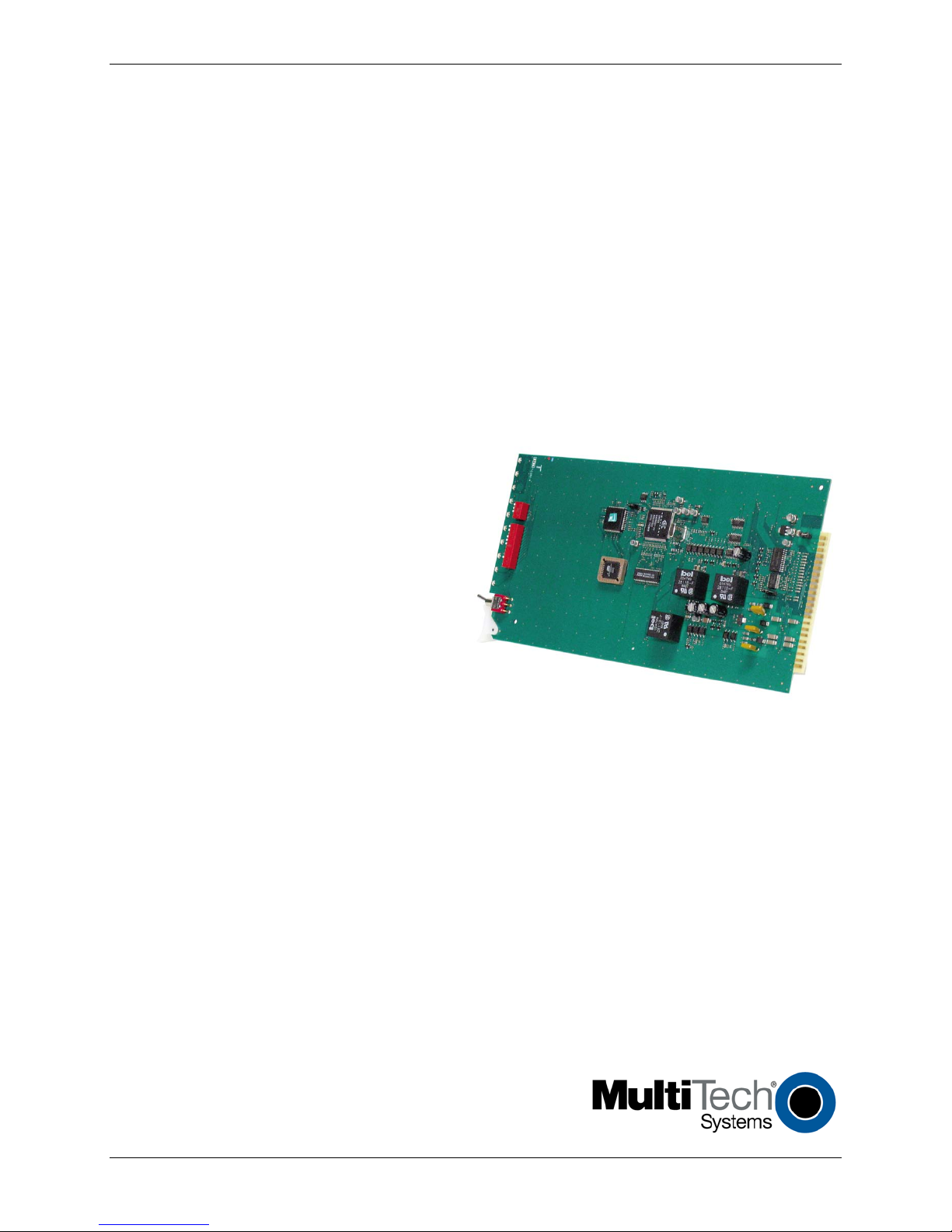
MT5600BR-V92
Configuration Guide
Page 2

Copyright and Technical Support
Contacting Multi-Tech
Knowledge Base
The Knowledge Base provides immediate access to support information and resolutions for all Multi-Tech products. Visit
http://www.multitech.com/kb.go.
Installation Resources
To download manuals, firmware, and software, visit http://www.multitech.com/setup/product.go.
Support Portal
To create an account and submit a support case directly to our technical support team, visit: https://support.multitech.com
Technical Support
Business Hours: M-F, 9am to 5pm CT
Country
By Email
By Phone
Europe, Middle East, Africa:
support@multitech.co.uk
+(44) 118 959 7774
U.S., Canada, all others:
support@multitech.com
(800) 972-2439 or (763) 717-5863
World Headquarters
Multi
-Tech Systems, Inc.
2205 Woodale Drive
Mounds View, Minnesota 55112
Phone: 763-785-3500 or 800-328-9717
Fax: 763-785-9874
Warranty
To read the warranty statement for your product, please visit: http://www.multitech.com/warranty.go
Data/Fax Rack Mounted Modem Card
MT5600BR-V.92
S000392D Revision D
Copyright
This publication may not be reproduced, in whole or in part, without prior expressed written permission from Multi-Tech Systems, Inc. All
rights reserved.
Copyright © 2006-2012, by Multi-Tech Systems, Inc.
Multi-Tech Systems, Inc. makes no representations or warranties with respect to the contents hereof and specifically disclaims any
implied warranties of merchantability or fitness for any particular purpose. Furthermore, Multi-Tech Systems, Inc. reserves the right to
revise this publication and to make changes from time to time in the content hereof without obligation of Multi-Tech Systems, Inc. to
notify any person or organization of such revisions or changes. Check Multi-Tech’s web site for current versions of our product
documentation.
Revision History
Revision Date Description
A 04/14/06 Initial Release
B 04/19/07 Updated Technical Support information
C 06/01/09 Updated switch settings for firmware release 7.02o and Technical Support information
D 01/12/12
Removed CD references. Added Multi-Tech Installation Resources site information. Removed rack
installation instructions and added reference to CC1600 documentation for rack installation.
Trademarks
Multi-Tech and the Multi-Tech logo are trademarks of Multi-Tech Systems, Inc.
Microsoft, Windows, Windows XP is a trademarks of Microsoft Corporation in the United States and/or other countries. All other
trademarks are owned by their respective companies.
Patents
This device is covered by one or more of the following patents: 6,031,867; 6,012,113; 6,009,082; 5,905,794; 5,864,560; 5,815,567;
5,815,503; 5,812,534; 5,809,068; 5,790,532; 5,764,628; 5,764,627; 5,754,589; 5,724,356; 5,673,268; 5,673,257; 5,644,594; 5,628,030;
5,619,508; 5,617,423; 5,600,649; 5,592,586; 5,577,041; 5,574,725; 5,559,793; 5,546,448; 5,546,395; 5,535,204; 5,500,859; 5,471,470;
5,463,616; 5,453,986; 5,452,289; 5,450,425; 5,355,365; 5,309,562; 5,301,274. Other patents pending.
2 Data/Fax Rack Mounted Modem Card Configuration Guide
Page 3

Contents
Chapter 1 – Product Description and Specifications .............................................................................5
Overview .....................................................................................................................................5
Telecom Safety Warnings .............................................................................................................5
Technical Specifications ...............................................................................................................6
Chapter 2 – Hardware Settings ...........................................................................................................7
Setting DIP Switches ....................................................................................................................7
DIP Switches 1-12............................................................................................................................. 7
DIP Switches 13-16........................................................................................................................... 8
OOS (Busy Out) Toggle Switch ......................................................................................................8
Out of Service Test Jumper ...........................................................................................................8
LED Indicators ..............................................................................................................................9
Chapter 3 – Software Configuration .................................................................................................. 10
Configuring Communications Software ....................................................................................... 10
PC Initialization Strings .................................................................................................................. 10
Changing Default Parameters ........................................................................................................ 11
Macintosh Initialization Strings ...................................................................................................... 11
Configuring the Modem for Your Country or Region .................................................................... 11
Using the Global Wizard ................................................................................................................ 11
Installing the Global Wizard ........................................................................................................... 11
Selecting the Country through the Global Wizard ......................................................................... 12
Using AT Commands to set Country or Region .............................................................................. 12
Appendix A - Regulatory Compliance ................................................................................................ 13
47 CFR Part 68 Telecom .............................................................................................................. 13
47 CFR Part 15 Regulation .......................................................................................................... 14
Fax Branding Statement ............................................................................................................. 15
Canadian Limitations Notice ....................................................................................................... 15
Industry Canada ......................................................................................................................... 15
EMC, Safety, and R&TTE Directive Compliance ............................................................................ 16
International Modem Restrictions .............................................................................................. 16
New Zealand Telecom Warning Notice ....................................................................................... 16
South African Statement ............................................................................................................ 17
Other ......................................................................................................................................... 17
WEEE Statement ........................................................................................................................ 18
Data/Fax Rack Mounted Modem Card Configuration Guide 3
Page 4

Contents
WEEE Directive ............................................................................................................................... 18
Instructions for Disposal of WEEE by Users in the European Union .............................................. 18
Appendix B – Upgrading Firmware ................................................................................................... 19
Checking the Modem Firmware Version ..................................................................................... 19
Checking the Current Firmware Version ...................................................................................... 19
Downloading and Installing the Flash Wizard .............................................................................. 20
Extracting the Upgrade Files ....................................................................................................... 20
Clearing Your Stored Parameters ................................................................................................ 20
Upgrading the Modem’s Firmware ............................................................................................. 20
Restoring Your Parameters ......................................................................................................... 21
Appendix C – ASCII Conversion Table ................................................................................................ 22
Index ............................................................................................................................................... 24
4 Data/Fax Rack Mounted Modem Card Configuration Guide
Page 5

Chapter 1 – Product Description and
Specifications
Overview
The MT5600BR-V92 modem card was designed for the CC1600 Series card cage. It uses ITU-T V.92
protocol to provide quick connections, capable of downstream transmissions at speeds up to 56K bps*,
and upstream transmissions at speeds up to 48K bps when connected to V.92-compatible Internet
service providers.
This document is a configuration guide for the MT5600BR-V92. It includes information on DIP switches,
toggles, and LEDs. It does not include instructions for installing this modem card in a rack. Refer to
related documentation for details.
● CC1600 Series Card Cage User Guide (Installation) (S000325)
● MultiModem II AT Command Reference Guide (S000373)
● Fax Service Class 1 and 1.0 Developer’s Guide (S000262)
● Fax Service Class 2, 2.0, and 2.1 Developer’s Guide (S000239)
To download these documents, go to
model from the Product drop down list.
http://www.multitech.com/setup/product.go and select your
Telecom Safety Warnings
● Never install telephone wiring during a lightning storm.
● Disconnect this product from the power source and telephone network interface when servicing.
● Use this product with UL and cUL listed computers.
● Never touch uninsulated telephone wires or terminals unless the telephone line has been
disconnected at the network interface.
● Use caution when installing or modifying telephone lines.
● Avoid using a telephone (other than a cordless type) during an electrical storm. There may be a
remote risk of electrical shock from lightning.
● Do not use a telephone in the vicinity of a gas leak – not even to report a gas leak.
● To reduce the risk of fire, use only 26 AWG or larger telecommunication line cord.
● Never install a telephone jack in wet locations unless the jack is specifically designed for wet
locations.
Data/Fax Rack Mounted Modem Card Configuration Guide 5
Page 6
Chapter 1 — Product Description and Specifications
Model Number
MT5600BR-V92
Mode of Operation
Full duplex data over dial-up line, 2-wire and 4-wire lease line; automatic or
Flow Control
XON/XOFF (software), RTS/CTS (hardware)
Command Buffer
60 Characters
Diagnostics
Power-on Self Test and Local analog loop
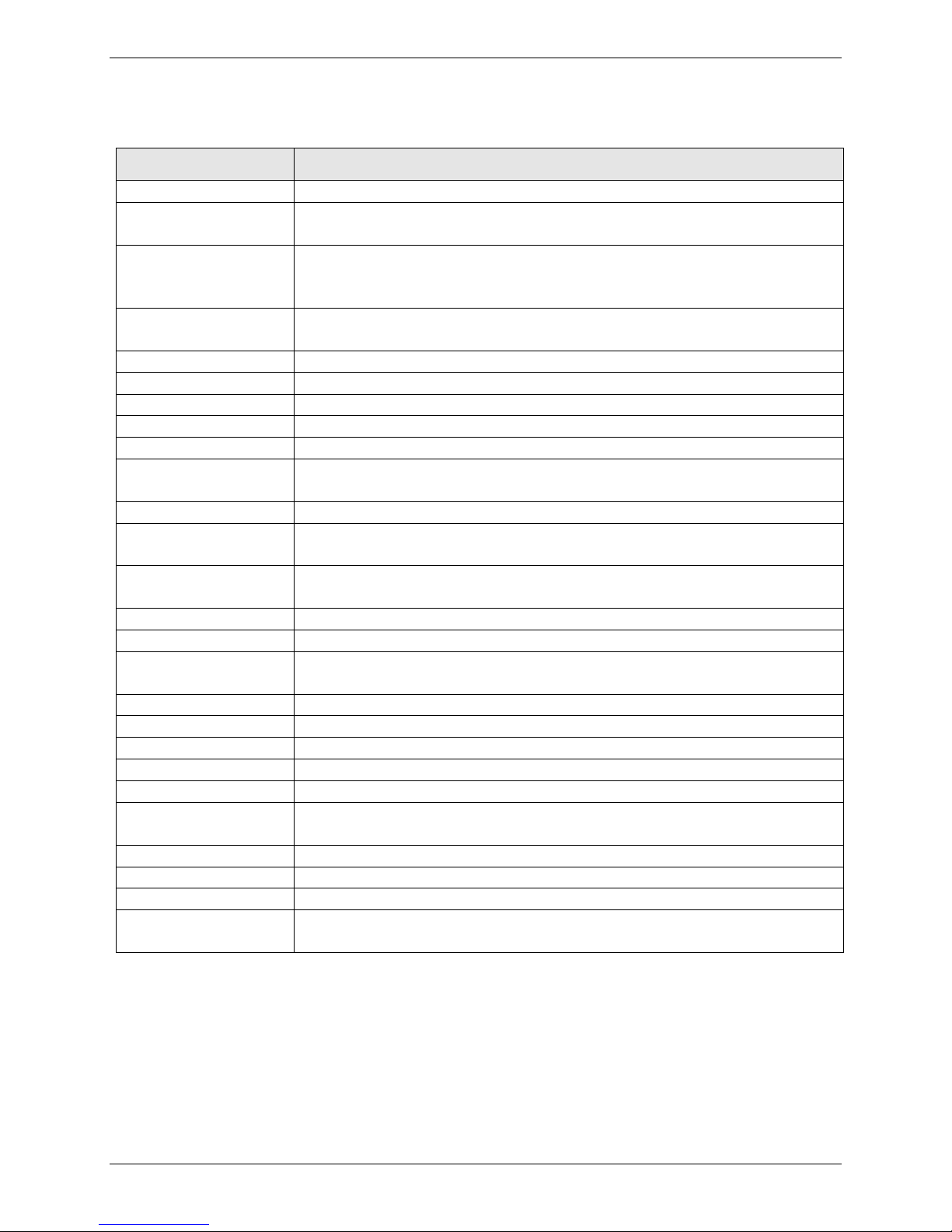
Technical Specifications
Your MT5600BR-V92 data/fax modem meets the specifications listed below:
Category
Server-to-Client Data
Rates
Client-to-Server Data
Rates
Client-to-Client Data
Rates
Fax Data Rates 14400, 12000, 9600, 7200, 4800, 2400, 1200, 0-300 bps
Data Format Serial, binary, asynchronous, synchronous
Fax Compatibility T.4, T30, V.21, V.27terV.29, V.34, V.17; TIA/EIA 578 Class 1, 1.0, 2TR29.2
Video Compatibility ITU-T V.80 for H.34 video conferencing
Error Correction ITU-T V.42 (LAP-M or MNP 4)
Data Compression ITU-T V.44 (6:1 throughput), V.42bis (4:1 throughput), MNP 5 (2:1
Speed Detection Automatic speed detection and switching between available speeds
Speed Conversion Serial port data rates adjustable to 300; 1200; 2400; 4800; 9600; 19,200;
V.90 speeds when accessing a V.90 or V.92 server (actual speed depends on
server capabilities and line conditions)*
Up to 50Kbps when accessing a V.92 server (actual speed depends on server
capabilities and line conditions); otherwise, the same as client-to-client data
lines.
33600,31200, 28800, 26400, 24000, 21600, 19200, 16800,
14400, 12000, 9600, 7200, 4800, 2400, 1200, 0-300 bps
throughput)
38,400; 57,600; 115,200 bps
manual dialing, automatic or manual answer
Description
Transmission Level -11 dBm (dial-up), -15dBm (lease line); dBm level selectable with DIP-Switch
#3 in lease line setting
Frequency Stability ±0.01%
Receiver Sensitivity -43 dBm under worst-case conditions
AGC Dynamic Range 43 dB
Interface EIA RS232C/ITU-TSS V.24
Environmental Temperature range 0°–50°C (32°–120°F); humidity range 20–90% (non-
condensing)
Storage Temperature -10° to +85°C (14°- 185° F)
Dimensions 10½ wide x 5½ long
Weight 8 oz
Operating Systems Tested for use with Windows 98, NT, 2000, XP, 2003 Server and Linux (2.2.x
kernel)
* Although this modem is capable of 56K bps download performance, line impairments, phone
infrastructure, and other external factors may prevent maximum 56K bps connections.
Note: Transmissions between the MT5600BR-V92 and other modems are limited to 33.6K bps, as
are upstream transmissions to non-V.92-compatible ISPs and downstream transmissions that
are converted more than once on the telephone network.
6 Data/Fax Rack Mounted Modem Card Configuration Guide
Page 7
Chapter 2 – Hardware Settings
Down
DTR dependent on interface
Down
Software flow control
SDLC*/BSC (Sync)
Up*
SDLC mode
Down
BSC mode
3
Result Codes Enabled*
Up
Q1 Disable Responses
Down*
Q0 Enable Responses
DbM Transmit -15dB/-11dB*
Up
Lease Line
Read switches in SYNC*
Up*
AS/400 Mode OFF
Down
AS/400 Mode ON
5
Auto-Answer Enabled*
Up*
Enable Auto Answer
Down
Disable Auto Answer
Down
Slave Clocking ON
Up
RTS dependent on interface
Down*
RTS forced ON
8
Command Mode Enabled*
Up
Disable Command Mode
Down
Enabled Command Mode
This chapter describes the modem card DIP Switches, toggle switches, berg jumper, and LEDs.
Setting DIP Switches
The MT5600-V92 modem card contains sixteen DIP switches. How a switch operates depends on
whether the modem is in synchronous or asynchronous mode (DIP switch #12).
Factory defaults are set to use the MT5600BR-V92 to dial up a remote installation where the call is
answered automatically. Your communications software may require different settings. For the correct
DIP switch settings, check your software’s documentation.
Before you install modem cards in the card cage, verify that the DIP switch settings are correct for your
application (dial-up or lease line).
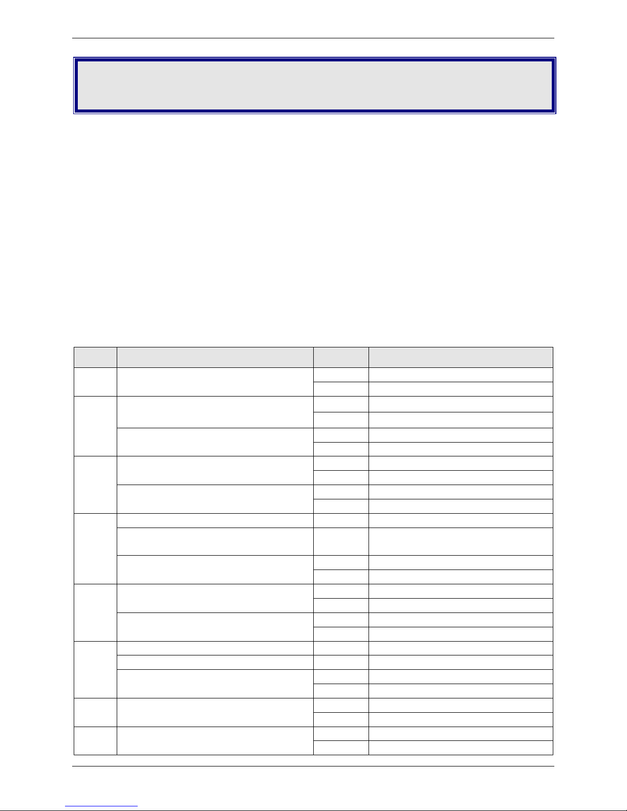
DIP Switches 1-12
*Factory default setting
Switch Function Position Effect
1 DTR Forced/DTR from Interface* Up* DTR forced ON at all times
2 Flow Control &E4*
(Async/Dial-Up/Leased Line)
(Async Dial-up)
(Async/Sync/Leased Line)
4 Read switches in ASYNC* Up* Follows DIP-Switch 6 settings
Ignores switches in ASYNC Down Uses stored parameters.
(Sync Dial-Up/Leased Line)
(Async/Sync/Dial-Up)
Answer/Originate*
(Async/Sync/Leased Line)
6 Max-Throughput Enabled* Up* Compression with error correction
Max - Throughput Disabled Down No compression or error correction
Slave Clock Disabled*
(Sync/Dial-Up/Leased)
7 RTS/Normal/Forced*
(Sync/Async/Dial/Leased)
Up* Hardware flow control
Down* Transmits at -11dB
Bypasses DIP-Switch 6 settings
Up* Answer Mode
Down Originate Mode
Up* Slave Clocking OFF
(Sync/Async/Dial/Leased)
Data/Fax Rack Mounted Modem Card Configuration Guide 7
Page 8
Chapter 2 — Hardware Settings
9
No affect
10
Dial-Up*/Leased-Line
Up*
Dial-Up Operation
Up/Up*
D Read from stored parameters for speed (Default V.92)
Down/UP
V.34 Operation
Up/Down
V.32b Operation
Down/Down
V.22b Operation
15
Up*
CD/DSR from Interface
Down
CD/DSR Forced On
16
Up
2-Wire Operation
Test Setting (Factory Default)
OOS Setting (Optional)
Switch Function Position Effect
Down Lease Line Operation
11 No affect in async
External Clocking (Sync) Up External Clock
Internal Clocking*(Sync) Down * Internal Clock
12 Sync Mode Up Synchronous Operation
Async Mode* Down * Asynchronous Operation
DIP Switches 13-16
*Factory default setting
Switch Position Effect
13/14
Down 4-Wire Operation
OOS (Busy Out) Toggle Switch
The front panel has a two-position out of service (OOS) switch. Use this switch to take the modem offhook, which creates a busy condition for the modem.
● Move the OOS toggle switch to BUSY to take the modem out of service. The OOS and OH LEDs light
and incoming calls get a busy signal.
If you suspect a modem is not working, use BUSY to have an optional device, such as a hunt group, roll
the call to the next available modem while you check the busy modem.
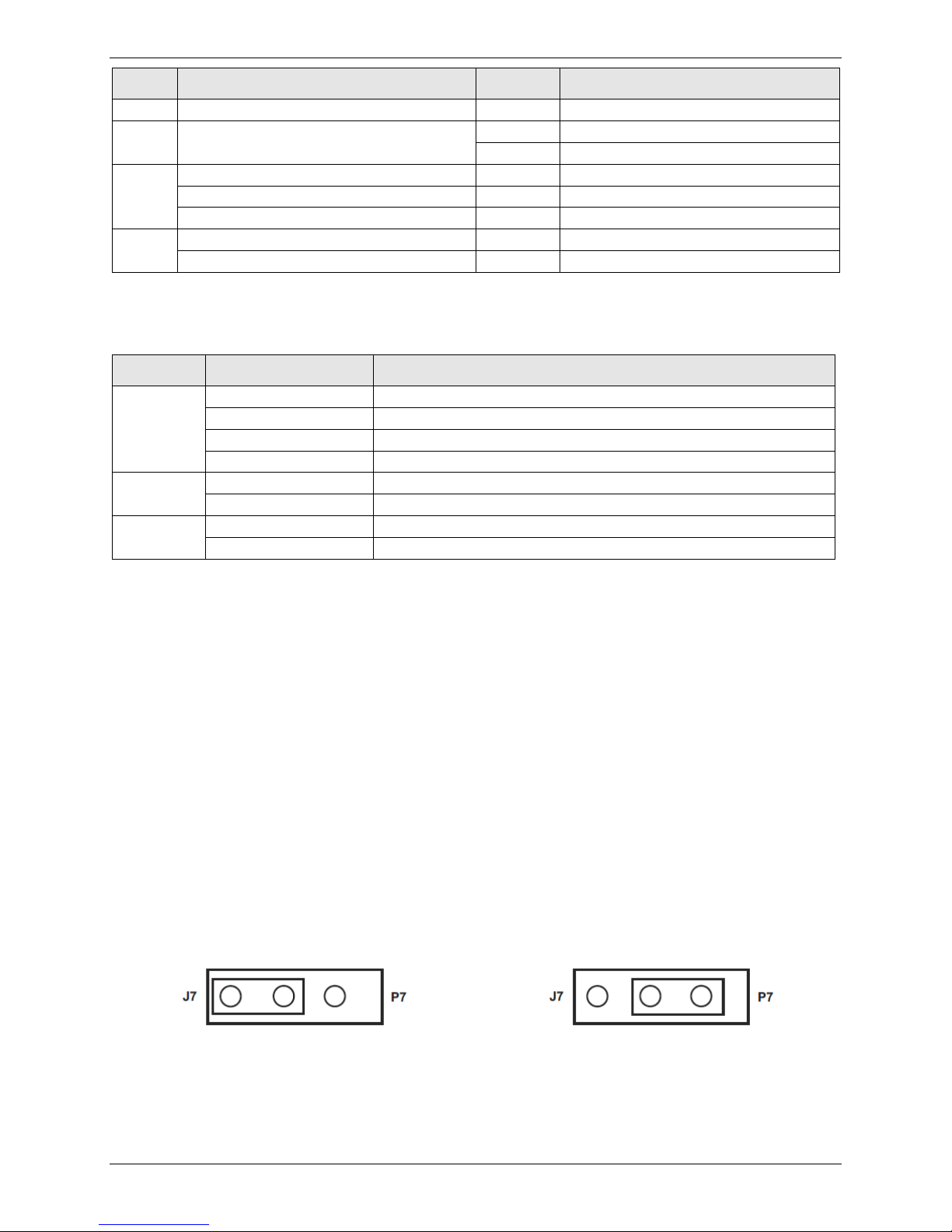
Out of Service Test Jumper
When the MT5600BR-V92 is out of service, it is busy to incoming calls. In the Test (default) setting, the
modem drives pin 25 high when the modem is in Test mode. The OOS (optional) setting forces pin 25
high and puts the modem in a busy condition.
Note: Jumper (shorting) plugs do not shipped with the MT5600BR-V92, but Multi-Tech Technical
Support will provide jumper plugs on request.
8 Data/Fax Rack Mounted Modem Card Configuration Guide
Page 9

LED Indicators
of the RS232C/V.24 interface.
CO
Lights when a valid carrier tone has been detected.
56
Lights when the modem connects using V.92 protocol. Actual connection speed depends on
33.6
Lights when the modem connects at 33,600 bps.*
14.4
Lights when the modem connects at 14,400 bps.*
matches that of the DTR circuit on Pin 20 of the RS232C/V.24 interface.
RI
Lights during the ringing interval when incoming call is received.
OOS
When the OOC LED is on, the modem is in an out of service (OOS) state. When the modem is
The MT5600BR-V92 has ten LED diagnostic indicators.
Chapter 2 — Hardware Settings
LED
RCV Blinks while receiving data. The RCV LED state matches that of the RCV circuit on Pin 3 of the
RS232C/V.24 interface.
XMT Blinks while transmitting data. The XMT LED state matches that of the XMT circuit on Pin 2
ISP server capabilities and line conditions.
OH Lights when the phone line is off-hook. This occurs when the modem is dialing, on line,
answering a call, or when the OOS toggle is set to BUSY.
This LED flashes when the modem is pulse dialing in the Command Mode.
DTR When the DTR LED is lit, the modem is permitted to answer an incoming call. When the DTR
LED is off, if the modem is dependent on DTR, it disconnects. The state of this DTR LED
out of service, it is busy to incoming calls.
Description
* If both the 33.6 and 14.4 LEDs are lit, the modem is operating in the 16,800 to 33,600bps mode.
Data/Fax Rack Mounted Modem Card Configuration Guide 9
Page 10

Chapter 3 – Software Configuration
Configuring Communications Software
Configure your communications software to work with your modem, your computer, and the remote
system it calls. Most communications programs provide a default initialization string and default settings
for other parameters.
To configure you communications software to work with the MT5600BR-V92 modem:
● Set the modem initialization string.
This is a command sequence that the software uses to configure the modem when loading
communications software or beginning a session.
● Always begin the initialization string with AT.
● Follow the AT with the modem reset command, &F, to ensure that you are starting with a
known state.
● Additional commands depend on the modem’s capabilities and what you want it to do.
● Newer communications programs provide initialization strings when you select your model from
a list. If the MT5600BR-V92 is not listed, select MultiModemII.
Note: Modem capabilities and command implementations vary from modem to modem. If you
use an initialization string intended for another modem, particularly one from another
manufacturer, you might not have access to some modem features.
PC Initialization Strings
We recommend the following initialization string for a MT5600BR-V92 connected to a PC-compatible
computer:
AT &F X4 S0=0 ^M
This string:
● Resets the MT5600BR-V92 to the factory default settings
● Selects extended result codes with NO DIAL TONE and BUSY, and turns off auto-answer.
Notes: If you send commands through communications software, you must end every string with ^M.
This is the ASCII code for the Return key on most keyboards, the default code for carriage
return in the MT5600BR-V92, and most communications programs.
If you send commands to the modem in terminal mode, you must press Return (<CR>) to end
every string.
In the MT5600BR-V92, the carriage return character is defined in S-register S3. If you change
it, also change the carriage return character code used in your communications software.
10 Data/Fax Rack Mounted Modem Card Configuration Guide
Page 11

Chapter 3 — Software Configuration
Changing Default Parameters
The default values for the other parameters in modem configuration menus rarely need changing. They
typically include the dialing prefix (ATDT for touch-tone service and ATDP for rotary service), the dialing
suffix (^M), the hang-up string (+++) Response then (ATH0^M), and response messages (RING, NO
CARRIER, BUSY, etc.). Communications software with a host mode might include an auto-answer string
(AT S0=1^M).
Macintosh Initialization Strings
● To use RTS/CTS hardware flow control with a Macintosh computer, you must use serial cable wired
for hardware control.
● Macintosh 128 and 512 models cannot use RTS/CTS flow control at all. For these models, use the
following string to turn off the default RTS/CTS hardware flow control, turn on XON/XOFF flow
control, and ignore DTR: AT &F X4 &k4 &D0 ^M
● For hardware flow control, use the following initialization string AT &F X4 &K3 &D0 ^M
● Add S0=0 to both strings to disable auto-answer if the MT5600BR-V92 is on a voice line.
To store the initialization string in nonvolatile memory:
1. With your communications software open and connected to the modem’s COM port, type the
initialization string in the terminal window, substituting a carriage return for ^M.
2. Enter AT &W0 <CR>.
When the initialization string is stored, you can use the following string to initialize your modem:
AT Z ^M
Configuring the Modem for Your Country or
Region
Different countries have different requirements for how modems must function. Before using your
modem, configure it for country/region in which you are using it. You can use either the Global Wizard
or AT Commands to configure the modem for your country.
Using the Global Wizard
If using your modem with a Windows operating system, use the Global Wizard software to set the
country. This is available through the Multi-Tech Installation Resources site.
Installing the Global Wizard
1. Go to http://www.multitech.com/setup/product.go and select your model from the Product drop
down list.
2. Click Software.
3. Click Global Wizard link.
4. Click Run twice. The Global Wizard installer launches.
5. Click Next.
6. Click Yes.
7. Click Next.
8. Click Finish. This completes the Global Wizard installation.
Data/Fax Rack Mounted Modem Card Configuration Guide 11
Page 12

Chapter 3 — Software Configuration
Country/Region
AT Command (hexadecimal)
Result code (decimal)
Selecting the Country through the Global Wizard
1. Click Start | All Programs |Global Wizard and select Global Wizard. The Global Wizard opens.
2. Click Next. The Global Wizard searches for your modems and identifies them.
3. Click Next. Select a modem to configure.
4. Click Next.
5. Select the country in which the modem will be used and click Next.
6. Review your choice of country. If it is correct, click Next to configure the modem.
7. When Global Wizard announces that the parameters have been set, click Finish to exit.
Using AT Commands to set Country or Region
Non-Windows users can configure the modem using AT commands. You must enter these commands in
your communication program’s terminal window. To configure the country/region code, the
initialization string must contain the AT command for your specific country or region.
1. Run a communications program, such as HyperTerminal.
2. Type AT%T19,0,nn, where nn is the country/region code in hexadecimal notation.
3. Click Enter. The message OK displays.
4. To verify that the correct country/region has been configured, type: ATI9 and click Enter.
The country/region code displays, for example:
Euro/NAM AT%T19,0,34 (default) 52
A list of country/region codes can be found on the Multi-Tech Web site at
http://www.multitech.com/global/approvals.go.
12 Data/Fax Rack Mounted Modem Card Configuration Guide
Page 13

Appendix A - Regulatory
Compliance
47 CFR Part 68 Telecom
This equipment complies with Part 68 of the 47 CFR rules and the requirements adopted by the ACTA.
Located on this equipment is a label that contains, among other information, the registration number
and ringer equivalence number (REN) for this equipment or a product identifier in the format:
● For current products is US:AAAEQ##Txxxx.
● For legacy products is AU7USA-xxxxx-xx-x.
If requested, this number must be provided to the telephone company.
1. A plug and jack used to connect this equipment to the premises wiring and telephone network must
comply with the applicable 47 CFR Part 68 rules and requirements adopted by the ACTA. It’s
designed to be connected to a compatible modular jack that is also compliant.
2. The ringer equivalence number (REN) is used to determine the number of devices that may be
connected to a telephone line. Excessive RENs on a telephone line may result in the devices not
ringing in response to an incoming call. In most but not all areas, the sum of RENs should not exceed
five (5.0). To be certain of the number of devices that may be connected to a line, as determined by
the total RENs, contact the local telephone company. For products approved after July 23, 2001, the
REN for this product is part of the product identifier that has the format US:AAAEQ##Txxxx. The
digits represented by ## are the REN without a decimal point (e.g., 03 is a REN of 0.3). For earlier
products, the REN is separately shown on the label.
3. If this equipment causes harm to the telephone network, the telephone company will notify you in
advance that temporary discontinuance of service may be required. But if advance notice isn't
practical, the telephone company will notify the customer as soon as possible. Also, you will be
advised of your right to file a complaint with the FCC if you believe it is necessary.
4. The telephone company may make changes in its facilities, equipment, operations or procedures
that could affect the operation of the equipment. If this happens, the telephone company will
provide advance notice in order for you to make necessary modifications to maintain uninterrupted
service.
5. If trouble is experienced with this equipment, please contact Multi-Tech Systems, Inc. at the address
shown below for details of how to have the repairs made. If the equipment is causing harm to the
telephone network, the telephone company may request that you disconnect the equipment until
the problem is resolved.
6. Connection to party line service is subject to state tariffs. Contact the state public utility commission,
public service commission or corporation commission for information.
7. No repairs are to be made by you. Repairs are to be made only by Multi-Tech Systems or its
licensees. Unauthorized repairs void registration and warranty.
8. If your home has specially wired alarm equipment connected to the telephone line, ensure the
installation of this equipment does not disable your alarm equipment.
Data/Fax Rack Mounted Modem Card Configuration Guide 13
Page 14

Appendix A — Regulatory Compliance
Trade Name
MultiModem® II
Model Number:
MT5600BR-V92
Modular Jack (USOC):
RJ11C
9. If you have questions about what will disable alarm equipment, consult your telephone company or
a qualified installer.
10. Connection to party line service is subject to state tariffs. Contact the state public utility commission,
public service commission or corporation commission for information.
11. If so required, this equipment is hearing-aid compatible.
12. Manufacturing information:
Manufacturer: Multi-Tech Systems, Inc.
FCC Registration No: AU7USA32234--M5-E
Ringer Equivalence No: 0.4B
Service Center in USA: Multi-Tech Systems, Inc.
2205 Woodale Drive
Mounds View, MN 55112
U.S.A.
47 CFR Part 15 Regulation
This equipment has been tested and found to comply with the limits for a Class A digital device,
pursuant to 47 CFR Part 15 regulations. The stated limits in this regulation are designed to provide
reasonable protection against harmful interference in a commercial environment. This equipment
generates, uses, and can radiate radio frequency energy, and if not installed and used in accordance
with the instructions, may cause harmful interference to radio communications. However, there is no
guarantee that interference will not occur in a particular installation. If this equipment does cause
harmful interference to radio or television reception, which can be determined by turning the
equipment off and on, the user is encouraged to try to correct the interference by one or more of the
following measures:
Reorient or relocate the receiving antenna.
Increase the separation between the equipment and receiver.
Plug the equipment into an outlet on a circuit different from that to which the receiver is connected.
Consult the dealer or an experienced radio/TV technician for help.
This device complies with Part 15 of the 47 CFR rules and with RSS-210 of Industry Canada. Operation of
this device is subject to the following conditions: (1) This device may not cause harmful interference,
and (2) this device must accept any interference that may cause undesired operation.
Warning: Changes or modifications to this unit not expressly approved by the party responsible for
compliance could void the user’s authority to operate the equipment.
14 Data/Fax Rack Mounted Modem Card Configuration Guide
Page 15

Appendix A — Regulatory Compliance
Fax Branding Statement
The Telephone Consumer Protection Act of 1991 makes it unlawful for any person to use a computer or
other electronic device, including fax machines, to send any message unless such message clearly
contains the following information:
● Date and time the message is sent
● Identification of the business, other entity, or other individual sending the message
● Telephone number of the sending machine or such business, other entity, or individual
This information is to appear in a margin at the top or bottom of each transmitted page or on the first
page of the transmission. This information in the margin is referred to as fax branding.
Any number of fax software packages can be used with this product. Refer to the fax software manual
for setup details. Typically, the fax branding information must be entered via the configuration menu of
the software.
Canadian Limitations Notice
Notice: The ringer equivalence number (REN) assigned to each terminal device provides an indication of
the maximum number of terminals allowed to be connected to a telephone interface. The termination
on an interface may consist of any combination of devices subject only to the requirement that the sum
of the ringer equivalence numbers of all the devices does not exceed 5.
Notice: The Industry Canada label identifies certified equipment. This certification means that the
equipment meets certain telecommunications network protective, operational, and safety
requirements. The Industry Canada label does not guarantee the equipment will operate to the user’s
satisfaction.
Before installing this equipment, users should ensure that it is permissible to be connected to the
facilities of the local telecommunications company. The equipment must also be installed using an
acceptable method of connection. The customer should be aware that compliance with the above
conditions may not prevent degradation of service in some situations. Repairs to certified equipment
should be made by an authorized Canadian maintenance facility designated by the supplier. Any repairs
or alterations made by the user to this equipment or equipment malfunctions may give the
telecommunications company cause to request the user to disconnect the equipment.
Users should ensure for their own protection that the electrical ground connections of the power utility,
telephone lines and internal metallic water pipe system, if present, are connected together. This
precaution may be particularly important in rural areas.
Caution: Users should not attempt to make such connections themselves, but should contact the
appropriate electric inspection authority, or electrician, as appropriate.
Industry Canada
This Class A digital apparatus meets all requirements of the Canadian Interference-Causing Equipment
Regulations.
Cet appareil numérique de la classe A respecte toutes les exigences du Reglement Canadien sur le
matériel brouilleur.
Data/Fax Rack Mounted Modem Card Configuration Guide 15
Page 16

Appendix A — Regulatory Compliance
EMC, Safety, and R&TTE Directive Compliance
The CE mark is affixed to this product to confirm compliance with the following European Community
Directives:
Council Directive 2004/108/EC of 15 December 2004 on the approximation of the laws of Member
States relating to electromagnetic compatibility;
and
Council Directive 2006/95/EC of 12 December 2006 on the harmonization of the laws of Member
States relating to electrical equipment designed for use within certain voltage limits;
and
Council Directive 1999/5/EC of 9 March 1999 on radio equipment and telecommunications terminal
equipment and the mutual recognition of their conformity.
International Modem Restrictions
Some dialing and answering defaults and restrictions may vary for international modems. Changing
settings may cause a modem to become non-compliant with national regulatory requirements in specific
countries. Also note that some software packages may have features or lack restrictions that may cause
the modem to become non-compliant.
New Zealand Telecom Warning Notice
1. The grant of a Telepermit for any item of terminal equipment indicates only that Telecom has
accepted that the item complies with minimum conditions for connection to its network. It
indicates no endorsement of the product by Telecom, nor does it provide any sort of warranty.
Above all, it provides no assurance that any item will work correctly in all respects with another item
of Telepermitted equipment of a different make or model, nor does it imply that any product is
compatible with all of Telecom’s network services.
This equipment is not capable under all operating conditions of correct operating conditions of
correct operation at the higher speed which it is designated. 33.6 kbps and 56 kbps connections are
likely to be restricted to lower bit rates when connected to some PSTN implementations. Telecom
will accept no responsibility should difficulties arise in such circumstances.
2. Immediately disconnect this equipment should it become physically damaged, and arrange for its
disposal or repair.
3. This modem shall not be used in any manner which could constitute a nuisance to other Telecom
customers.
4. This device is equipped with pulse dialing, while the Telecom standard is DTMF tone dialing. There is
no guarantee that Telecom lines will always continue to support pulse dialing.
Use of pulse dialing, when this equipment is connected to the same line as other equipment, may
give rise to 'bell tinkle' or noise and may also cause a false answer condition. Should such problems
occur, the user should NOT contact the Telecom Faults Service.
16 Data/Fax Rack Mounted Modem Card Configuration Guide
Page 17

Appendix A — Regulatory Compliance
The preferred method of dialing is to use DTMF tones, as this is faster than pulse (decadic) dialing
and is readily available on almost all New Zealand telephone exchanges.
5. Warning Notice: No '111' or other calls can be made from this device during a mains power failure.
6. This equipment may not provide for the effective hand-over of a call to another device connected to
the same line.
7. Some parameters required for compliance with Telecom’s Telepermit requirements are dependent
on the equipment (PC) associated with this device. The associated equipment shall be set to operate
within the following limits for compliance with Telecom’s Specifications:
For repeat calls to the same number:
● There shall be no more than 10 call attempts to the same number within any 30 minute period
for any single manual call initiation, and
● The equipment shall go on-hook for a period of not less than 30 seconds between the end of
one attempt and the beginning of the next attempt.
For automatic calls to different numbers:
● The equipment shall be set to ensure that automatic calls to different numbers are spaced such
that there is no less than 5 seconds between the end of one call attempt and the beginning of
another.
8. For correct operation, total of the RN’s of all devices connected to a single line at any time should
not exceed 5.
South African Statement
This modem must be used in conjunction with an approved surge protection device.
Other
The above country-specific examples do not cover all countries with specific regulations; they are
included to show you how each country may differ. If you have trouble determining your own country's
requirements, check with Multi-Tech's Technical Support for assistance.
Data/Fax Rack Mounted Modem Card Configuration Guide 17
Page 18

Appendix A — Regulatory Compliance
WEEE Statement
(Waste Electrical and Electronic Equipment)
WEEE Directive
The WEEE directive places an obligation on EU-based manufacturers, distributors, retailers, and
importers to take-back electronics products at the end of their useful life. A sister Directive, ROHS
(Restriction of Hazardous Substances) complements the WEEE Directive by banning the presence of
specific hazardous substances in the products at the design phase. The WEEE Directive covers all MultiTech products imported into the EU as of August 13, 2005. EU-based manufacturers, distributors,
retailers and importers are obliged to finance the costs of recovery from municipal collection points,
reuse, and recycling of specified percentages per the WEEE requirements.
Instructions for Disposal of WEEE by Users in the
European Union
The symbol shown below is on the product or on its packaging, which indicates that this product must
not be disposed of with other waste. Instead, it is the user’s responsibility to dispose of their waste
equipment by handing it over to a designated collection point for the recycling of waste electrical and
electronic equipment. The separate collection and recycling of your waste equipment at the time of
disposal will help to conserve natural resources and ensure that it is recycled in a manner that protects
human health and the environment. For more information about where you can drop off your waste
equipment for recycling, please contact your local city office, your household waste disposal service or
where you purchased the product.
July, 2005
18 Data/Fax Rack Mounted Modem Card Configuration Guide
Page 19

Appendix B – Upgrading Firmware
Your modem is controlled by semi-permanent firmware, which is stored in flash memory. Multi-Tech's
firmware remains stored in memory when the modem is turned off and can be upgraded as new
features are added.
Checking the Modem Firmware Version
Check the current firmware version to determine if an update is needed:
1. Run a terminal program, such as HyperTerminal.
2. In the terminal window, type AT&F. Even if you cannot see the AT&F command on your screen, be
sure to type it completely, and then press Enter. If the modem does not respond with OK, repeat the
AT&F command.
3. Now type ATI3, press Enter and record your results. The firmware version should appear first in the
response, for example:
ACF3_V1.702a_V90_P21_FSH
The number after the V is the current version number.
Checking the Current Firmware Version
Identify the current version of the firmware at the Multi-Tech site. If your modem already has the
current firmware, there is no need to update it.
3. Go to http://www.multitech.com/setup/product.go and select your model from the Product drop
down list.
4. Click Firmware. The firmware zip file name contains the version number. For example,
hhgg702o.zip, indicates version 702o.
5. Compare the version number on the modem to the version on the site. If the versions match, there
is no need to update.
Make sure you compare any letters following the version number. If there was a minor release, the
letter may change instead of the number.
Warning: The first digit of the new firmware must match the first digit of the old firmware, or the
modem may not work properly; e.g., if your current firmware version is 4.16, replace it only
with 4.xx firmware, not 6.xx firmware.
Data/Fax Rack Mounted Modem Card Configuration Guide 19
Page 20

Appendix B — Upgrading Firmware
Downloading and Installing the Flash Wizard
1. If you are not on the MT5600BR-V92 page, go to http://www.multitech.com/setup/product.go and
select the model from the Product drop down list.
2. Click Software.
3. Click the Flash Wizard utility link and click Open.
4. Click Next to start through the Flash Wizard installation. Note the folder where the Flash Wizard will
be installed; you’ll need to extract the upgrade file to the same location.
5. Click Next and then click Finish.
Extracting the Upgrade Files
1. Click Firmware and then click the firmware upgrade link.
2. Click Open and then click Extract.
3. Select the folder where you installed the Flash Wizard and click Extract. The default folder is
C:\Program Files\Multi-Tech Systems\Flash Wizard.
Clearing Your Stored Parameters
Before you flash your modem, record the parameters that are currently stored in it, so you can
reprogram it after flashing. After you have recorded them, send the AT&F command to reset the
modem to clear the stored parameters.
1. Run your favorite terminal program, such as HyperTerminal.
2. In the program’s terminal window, type AT&V and press Enter to list your modem’s current
parameters.
3. Record your parameters by saving the screens and sending them to your printer.
4. Type AT&F and press Enter to clear your stored parameters and reset your modem to factory
default.
5. Close the terminal program.
Upgrading the Modem’s Firmware
Warning: Never install an older version of firmware over a newer version. This destroys the flash
PROM! If the flash PROM is destroyed, the modem must be sent in for repair.
1. Click Start | Programs | Flash Wizard to launch the Flash Wizard. The Identifying Devices dialog box
is displayed as Flash Wizard locates and identifies the devices connected to your system.
Note: If the message ERROR: No valid devices detected is displayed, verify that the modem is
turned on and that all cables are correctly and securely attached.
2. Select the modem to be upgraded, and then click Next.
3. Select the port to be upgraded and the appropriate .HEX file, and then click Next.
Note: Do not use FLASHLDR.HEX. This file is used internally by Flash Wizard.
Caution: If the upgrade is disrupted at this state, your modem may become inoperable. Wait for
Next to become active before proceeding.
20 Data/Fax Rack Mounted Modem Card Configuration Guide
Page 21

Appendix B — Upgrading Firmware
Programming Complete appears and Next becomes active when the flash upgrade is complete.
4. Click Next to continue.
5. Click Finish to exit the Flash Wizard.
Restoring Your Parameters
Your modem has been updated. Open your terminal program to reprogram your modem parameters or
to confirm the update by typing ATI3 in the terminal window and pressing Enter.
Data/Fax Rack Mounted Modem Card Configuration Guide 21
Page 22

Appendix C – ASCII Conversion
Table
CTRL CODE HEX DEC CODE HEX DEC CODE HEX DEC CODE HEX DEC
@ NUL 00 0 SP 20 32 @ 40 64 ` 60 96
A SOH 01 1 ! 21 33 A 41 65 a 61 97
B STX 02 2 " 22 34 B 42 66 b 62 98
C ETX 03 3 # 23 35 C 43 67 c 63 99
D EOT 04 4 $ 24 36 D 44 68 d 64 100
E ENQ 05 5 % 25 37 E 45 69 e 65 101
F ACK 06 6 & 26 38 F 46 70 f 66 102
G BEL 07 7 ’ 27 39 G 47 71 g 67 103
H BS 08 8 ( 28 40 H 48 72 h 68 104
I HT 09 9 ) 29 41 I 49 73 i 69 105
J LF 0A 10 * 2A 42 J 4A 74 j 6A 106
K VT 0B 11 + 2B 43 K 4B 75 k 6B 107
L FF 0C 12 , 2C 44 L 4C 76 l 6C 108
M CR 0D 13 - 2D 45 M 4D 77 m 6D 109
N SO 0E 14 . 2E 46 N 4E 78 n 6E 110
O SI 0F 15 / 2F 47 O 4F 79 o 6F 111
P DLE 10 16 0 30 48 P 50 80 p 70 112
Q DC1 11 17 1 31 49 Q 51 81 q 71 113
R DC2 12 18 2 32 50 R 52 82 r 72 114
S DC3 13 19 3 33 51 S 53 83 s 73 115
T DC4 14 20 4 34 52 T 54 84 t 74 116
U NAK 15 21 5 35 53 U 55 85 u 75 117
V SYN 16 22 6 36 54 V 56 86 v 76 118
W ETB 17 23 7 37 55 W 57 87 w 77 119
X CAN 18 24 8 38 56 X 58 88 x 78 120
Y EM 19 25 9 39 57 Y 59 89 y 79 121
Z SUB 1A 26 : 3A 58 Z 5A 90 z 7A 122
[ ESC 1B 27 ; 3B 59 [ 5B 91 { 7B 123
\ FS 1C 28 < 3C 60 \ 5C 92 | 7C 124
] GS 1D 29 = 3D 61 ] 5D 93 } 7D 125
^ RS 1E 30 > 3E 62 ^ 5E 94 ~ 7E 126
_ US 1F 31 ? 3F 63 _ 5F 95 DEL 7F 127
22 Data/Fax Rack Mounted Modem Card Configuration Guide
Page 23

Appendix C — ASCII Conversion Table
SOH
Start of Header
FF
Form Feed
ETB
End Transmission Block
STX
Start of Text
CR
Carriage Return
CAN
Cancel
EOT
End of
Transmission
SI
Shift In
SUB
Substitute
ACK
Acknowledge
DC1
Device Control 1
S
File Separator
BEL
Bell or Alarm
DC2
Device Control 2
GS
Group Separator
HT
Horizontal Tab
DC4
Device Control 4
US
Unit Separator
LF
Line Feed
NAK
Negative Acknowledge
DEL
Delete
NUL Null, or all zeros VT Vertical Tab SYN Sync
ETX End of Text SO Shift Out EM End of Medium
ENQ Enquiry DLE Data Link Escape ESC Escape
BS Backspace DC3 Device Control 3 RS Record Separator
Data/Fax Rack Mounted Modem Card Configuration Guide 23
Page 24

Index
A
ASCII conversion table ..................................... 22
asynchronous ..................................................... 7
auto-answer ............................................... 10, 11
B
berg jumper ....................................................... 8
busy .................................................................... 8
C
Canadian limitations ........................................ 15
carriage return ................................................. 10
CE mark ............................................................ 16
configuration .................................................... 10
configure modem
AT commands ............................................... 12
Global Wizard ............................................... 11
country ............................................................. 11
D
data rates ........................................................... 6
DIP switches ....................................................... 7
DTR signal ......................................................... 11
E
EMC, Safety, and R&TTE Directive Compliance
...................................................................... 16
I
Industry Canada ............................................... 15
initialization string ........................................... 10
international modem restrictions.................... 16
N
New Zealand Telecom warning notice ............ 16
O
operating system compatibility ......................... 6
out of service toggle .......................................... 8
P
parameters ...................................................... 11
R
result codes...................................................... 10
S
safety warnings .................................................. 5
servicing your modem ..................................... 14
South African Statement ................................. 17
S-registers
S3 .................................................................. 10
synchronous ....................................................... 7
T
F
factory default settings ...................................... 7
fax branding statement .................................... 15
FCC 47 CFR
Part 15........................................................... 14
Part 68 Telelcom ........................................... 13
firmware upgrade ............................................ 19
flash upgrade ................................................... 19
Flash Wizard ..................................................... 20
flow control .................................................. 6, 11
G
Global Wizard ................................................... 11
24 Data/Fax Rack Mounted Modem Card Configuration Guide
telecom safety ................................................... 5
U
upgrade firmware ............................................ 19
W
Waste Electrical and Electronic Equipment ..... 18
X
XON/XOFF ........................................................ 11
 Loading...