

Page 1
MT5600BA/BL Series
MT5600BA–V.92
MT5600BA–V.90
MT5600BL–V.90
Data/Fax Modem
User Guide
Page 2

MultiModemII User Guide
MT5600BA–V.92, MT5600BA–V.90, MT5600BL–V.90
P/N S000276E Revision E
©2002-2004 by Multi-Tech Systems, Inc.
All rights reserved. This publication may not be reproduced, in whole or in part, without prior expressed
written permission from Multi-Tech Systems, Inc.
Multi-Tech Systems, Inc. makes no representations or warranties with respect to the contents hereof and
specifically disclaims any implied warranties of merchantability or fitness for any particular purpose.
Furthermore, Multi-Tech Systems, Inc. reserves the right to revise this publication and to make changes
in the content hereof without obligation of Multi-Tech Systems, Inc. to notify any person or organization of
such revisions or changes.
Record of Revisions
Revision Date Description
A 10/03/02 Initial release of MT5600BA Global V.92. (Also replaces S0000129 Rev. C - the
MT5600BA/BL User Guide).
B 02/17/03 Changed cover. Changed text to indicate that the following
are
implemented:
V.25bis HDLC NRZ?, V.25bis HDLC NRZI?, and V.25bis BISYNC
C 07/31/03 Added setting the country code using the LCD panel. Add country codes list.
D 05/28/04 Change the word to
E 12/09/04 Add Web site location of the country/region code list.
Trademarks
MultiModemII, Multi-Tech, and the Multi-Tech logo are trademarks of Multi-Tech Systems, Inc.
Adobe and Acrobat are trademarks of Adobe Systems Incorporated. Microsoft, Windows, Windows 98/
Me/NT/2000/XP are either registered trademarks or trademarks of Microsoft Corporation in the United
States and/or other countries. All other brand and product names mentioned in this publication are
trademarks or registered trademarks of their respective companies.
Warranty
For Multi-Tech Warranty, see Multi-Tech Web site at http://www.multitech.com/COMPANY/Policies/warranty/
Patents
This device is covered by one or more of the following patents: 6,031,867; 6,012,113; 6,009,082;
5,905,794; 5,864,560; 5,815,567; 5,815,503; 5,812,534; 5,809,068; 5,790,532; 5,764,628; 5,764,627;
5,754,589; 5,724,356; 5,673,268; 5,673,257; 5,644,594; 5,628,030; 5,619,508; 5,617,423; 5,600,649;
5,592,586; 5,577,041; 5,574,725; 5,559,793; 5,546,448; 5,546,395; 5,535,204; 5,500,859; 5,471,470;
5,463,616; 5,453,986; 5,452,289; 5,450,425; D353,598; 5,355,365; 5,309,562; 5,301,274. Other patents
pending.
country
to
country or region
.
World Headquarters
Multi-Tech Systems, Inc.
2205 Woodale Drive
Mounds View, MN 55112 U.S.A
Technical Support
Country By Email By Phone
Europe, Middle East, Africa: support@multitech.co.uk +(44) 118 959 7774
U.S., Canada, all others: support@multitech.com (800) 972-2439 or (763) 717-5863
Internet Address: http://www.multitech.com
Multi-Tech Systems, Inc. MT5600BA/BL Series User Guide (S000276E)
2
Page 3

MultiModemII User Guide Table of Contents
Table of Contents
Chapter 1 - Description and Features ......................................................................... 5
Product Description .............................................................................................. 5
About AT Commands ........................................................................................... 5
Features ............................................................................................................... 5
Safety Warnings................................................................................................... 6
Chapter 2 - Installation ............................................................................................... 7
Step 1 - Connect the Modem to Your System ...................................................... 7
Step 2 - Install the Modem Driver ......................................................................... 9
Removing an Old Modem Driver .......................................................................... 9
Step 3 - Setting Your Country or Region Code ................................................... 10
Step 4 - Install PhoneTools ................................................................................ 11
Chapter 3 - Using the Front Panel ............................................................................ 12
Modem Configuration ......................................................................................... 12
LED Indicators ................................................................................................... 12
Liquid Crystal Display (LCD) .............................................................................. 13
Option Selection .......................................................................................... 13
Menu Structure ............................................................................................ 13
Menu Overview .................................................................................................. 14
Status Trunk................................................................................................. 15
Basic Options Trunk..................................................................................... 16
Advanced Options Trunk .............................................................................. 18
Remote Configuration Options Trunk ........................................................... 20
Diagnostic Options Trunk ............................................................................. 20
Phone Number Memory Options Trunk ........................................................ 21
Caller ID Options Trunk ................................................................................ 21
Menu Options .............................................................................................. 22
Status .......................................................................................................... 22
Basic Options .............................................................................................. 23
Advanced Options ....................................................................................... 25
Remote Configuration Options..................................................................... 27
Diagnostic Options ...................................................................................... 27
Phone Number Memory Options ................................................................. 27
Caller ID Options ......................................................................................... 28
Chapter 4 - Leased Line Operation .......................................................................... 29
Two-Wire Setup ................................................................................................. 29
Four-Wire Setup ................................................................................................. 30
Dial Backup and Leased-Line Restoral .............................................................. 31
Dial Backup and Leased Line Restoral Setup .................................................... 31
Chapter 5 - Remote Configuration ............................................................................ 33
Basic Procedure................................................................................................. 33
Setup ................................................................................................................. 33
Changing the Remote Configuration Password.................................................. 33
Changing the Remote Escape Character ........................................................... 34
Chapter 6 - Callback Security ................................................................................... 35
Setup Procedures .............................................................................................. 35
Turning Callback Security On and Off ................................................................ 35
Assigning Callback Passwords .......................................................................... 36
Calling Procedure .............................................................................................. 38
Callback Security Commands ............................................................................ 39
Callback Assignments Form .............................................................................. 40
Multi-Tech Systems, Inc. MT5600BA/BL Series User Guide (S000276E)
3
Page 4

MultiModemII User Guide Table of Contents
Chapter 7 - Troubleshooting ..................................................................................... 41
None of the Indicators Light ............................................................................... 41
The Modem Does Not Respond to Commands .................................................. 42
The Modem Cannot Connect When Dialing ....................................................... 43
The Modem Disconnects While Online .............................................................. 44
The Modem Cannot Connect When Answering ................................................. 45
File Transfer Is Slower Than It Should Be .......................................................... 45
Data Is Being Lost .............................................................................................. 45
There Are Garbage Characters on the Monitor .................................................. 46
The Modem Doesn’t Work with Caller ID ........................................................... 46
Fax and Data Software Can’t Run at the Same Time ......................................... 46
Appendix A - Regulatory Compliance ....................................................................... 47
FCC Part 68 Telecom ........................................................................................ 47
Fax Branding Statement .................................................................................... 48
Canadian Limitations Notice............................................................................... 48
EMC, Safety, and R&TTE Directive Compliance ................................................ 49
International Modem Restrictions ....................................................................... 49
New Zealand Telecom Warning Notice .............................................................. 49
South African Notice .......................................................................................... 50
Appendix B - Technical Specifications ...................................................................... 51
Appendix C - Upgrading the Firmware...................................................................... 53
Introduction ........................................................................................................ 53
Upgrade Overview ............................................................................................. 57
Step 1 - Identify the Modem Firmware ............................................................... 57
Step 2 - Identify the Current Firmware Version .................................................. 58
Step 3 - Download the Upgrade File .................................................................. 58
Step 4 - Extract the Upgrade Files ..................................................................... 58
Step 5 - Clear Your Stored Paramenters............................................................ 59
Step 6 - Upgrade the Modem’s Firmware........................................................... 59
Step 7 - Restore Your Parameters ..................................................................... 59
Appendix D - Installing a Modem Under Linux .......................................................... 60
Introduction ........................................................................................................ 60
Standard Linux Serial Port Definitions ................................................................ 60
Installation .......................................................................................................... 60
Setup ................................................................................................................. 60
Appendix E - Pin Descriptions .................................................................................. 62
RS-232 Pin Descriptions .................................................................................... 62
RS-232 Cable Pinouts........................................................................................ 63
Leased Line Pinouts........................................................................................... 64
Index ........................................................................................................................ 65
Multi-Tech Systems, Inc. MT5600BA/BL Series User Guide (S000276E)
4
Page 5

Chapter 1 - Description and Features
CC
hapterhapter
C
hapter
CC
hapterhapter
Congratulations on your purchase of the MultiModemII modem. You have acquired one of the finest
intelligent data/fax modems available today from one of the world’s oldest modem manufacturers: MultiTech Systems, Inc. This user guide will help you install, configure, test and use your modem.
PP
rr
oductoduct
P
r
oduct
PP
rr
oductoduct
This modem supports two-wire and/or four-wire leased lines. The four-wire leased line includes the dial
backup and automatic leased line restoration features. Please note that, because leased-line operation
consists of two client modems connected to each other, the maximum leased line data rate is 33.6K bps.
The MT5600BA-V.92 modem supports both two-wire and four-wire leased lines.
The MT5600BA modem supports a two-wire leased line.
The MT5600BL modem supports a four-wire leased line.
The MultiModemII offers interactive automatic dialing. You can store four command lines or telephone
numbers of up to 30 characters each in the modem’s nonvolatile memory. The modem pulse- or tonedials, and recognizes dial tones and busy signals for reliable call-progress detection. It can also detect
AT&T calling card tones. It is FCC-registered for connection to telephone networks without notification to
the telephone company.
The MultiModemII front panel includes a liquid crystal display and four buttons, which together can be
used to either display the current connection status of the modem or to configure the modem. The
MultiModemII also can be configured through standard AT commands.
Descr Descr
Descr
Descr Descr
1 - Descr 1 - Descr
1 - Descr
1 - Descr 1 - Descr
FF
ee
aa
iptipt
ipt
iptipt
F
FF
ii
i
ii
oo
o
oo
e
ee
nn
n
nn
a
aa
tt
t
tt
urur
ur
urur
iptipt
ipt
iptipt
eses
es
eses
ii
oo
n andn and
i
o
n and
ii
oo
n andn and
AA
boutbout
A
bout
AA
boutbout
AT Commands for this product are published in a separate document and included on the
MT5600BA/BL System CD that accompanies your modem.
FF
ee
aa
F
e
a
FF
ee
aa
General
•
Complies with major international standards to ensure compatibility with other modems.
•
Uses DTMF and tone detection to distinguish data and fax calls when used with software that
supports these features.
•
Supports serial port speeds to 230.4K bps with compatible serial ports
•
Supports Caller ID (North American versions only).
•
Displays status and configuration information on a front panel LCD.
Data
•
Supports automatic fallback to slower speeds in noisy line conditions, and fall-forward to faster
speeds as conditions improve.
•
Supports both synchronous and asynchronous data transfer.
•
Support two-wire leased line operation. Also supports four-wire leased line operation with dial
backup and leased line restoration.
•
Supports callback security and remote configuration.
•
Supports AS400 applications.
•
Automatically disables compression when transferring already-compressed files.
•
Can autodial, redial, pulse (rotary) and touch-tone dial.
•
Detects dial tones and busy signals for reliable call-progress detection.
•
Compatible with the standard AT command set used by most communication programs.
•
Supports Plug and Play (PnP).
•
Can be flash upgraded.
Fax
•
Supports V.17, Class 1, and Group 3 fax standards, (V.92 support Class 2 also) allowing it to
communicate with other fax modems as well as with fax machines.
tt
t
tt
urur
ur
urur
AA
A
AA
eses
es
eses
TT
T
TT
C C
C
C C
oo
mmmm
o
mm
oo
mmmm
andsands
ands
andsands
Multi-Tech Systems, Inc. MT5600BA/BL Series User Guide (S000276E)
5
Page 6

SS
S
SS
Chapter 1 - Description and Features
afaf
etet
yy
WW
arar
af
et
y
afaf
etet
• Use this product only with UL- and CUL-listed computers.
• To reduce the risk of fire, use only 26 AWG or larger telephone wiring.
• Never install telephone wiring during a lightning storm.
• Never install a telephone jack in a wet location unless the jack is specifically designed for wet
• Never touch uninsulated telephone wires or terminals unless the telephone line has been
• Use caution when installing or modifying telephone lines.
• Avoid using a telephone during an electrical storm; there is a risk of electrical shock from
• Do not use a telephone in the vicinity of a gas leak.
W
yy
WW
locations.
disconnected at the network interface.
lightning.
ar
arar
ningning
ning
ningning
ss
s
ss
Multi-Tech Systems, Inc. MT5600BA/BL Series User Guide (S000276E)
6
Page 7
CC
hapterhapter
C
hapter
CC
hapterhapter
2 - Inst 2 - Inst
2 - Inst
2 - Inst 2 - Inst
alal
lala
la
lala
tt
t
tt
al
alal
Chapter 2 - Installation
ii
oo
nn
i
o
n
ii
oo
nn
Step 1 - CStep 1 - C
Step 1 - C
Step 1 - CStep 1 - C
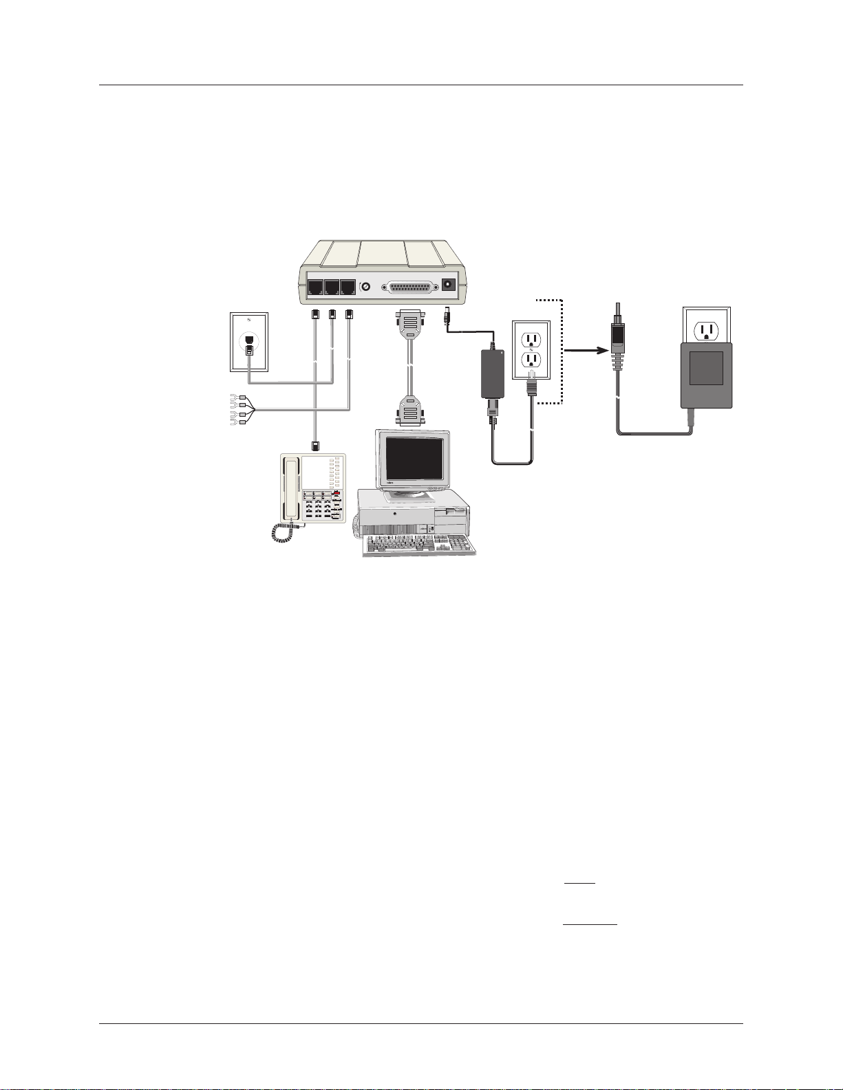
Turn off your computer. Placing the modem in a convenient location, connect it to your computer’s
serial port, to the telephone line, to your leased line, to AC power, and, optionally, to your telephone.
oo
nnenne
o
nne
oo
nnenne
ctct
ct
ctct
t t
he Modhe Mod
t
he Mod
t t
he Modhe Mod
LEASEDLINE
PHONE
VOLUME
em to em to
em to
em to em to
EIA RS232C
POWER
YY
ourour
Y
our
YY
ourour
or
Sy Sy
Sy
Sy Sy
stemstem
stem
stemstem
MultiModemII connections with V.92 transformer and V.90 transformer.
CC
oo
nnenne
C
o
nne
CC
oo
nnenne
Plug one end of the serial cable into the RS-232 connector on the modem, and the other end into a
serial port connector on your computer, such as COM1 or COM2.
CC
oo
nnenne
C
o
nne
CC
oo
nnenne
CC
oo
nnenne
C
o
nne
CC
oo
nnenne
Plug one end of the modular phone cable into the modem’s LINE jack, and the other end into a public
switched telephone network (PSTN) wall jack.
Important: The LINE jack is not interchangeable with the PHONE jack. Do not plug the phone into
the LINE jack or the line cable into the PHONE jack.
Note: Regulatory agencies may impose certain restrictions on equipment connected to public
telephone systems.
CC
oo
nnenne
C
o
nne
CC
oo
nnenne
MT5600BA – Plug one end of a two-wire phone cable into the modem’s LINE jack; connect the other
end to a leased line wall jack or terminals.
MT5600BL – Plug one end of a two-wire phone cable into the modem’s LEASED jack; connect the
other end to a leased line wall jack or terminals.
ctct
ct
ctct
ctct
ct
ctct
ctct
ct
ctct
ctct
ct
ctct
t t
t
t t
t t
t
t t
ii
i
ii
t t
t
t t
oo
o
oo
he Modhe Mod
he Mod
he Modhe Mod
he Modhe Mod
he Mod
he Modhe Mod
n)n)
n)
n)n)
heTheT
heT
heTheT
ww
w
ww
o-o-
o-
o-o-
em to em to
em to
em to em to
em to tem to t
em to t
em to tem to t
WW
irir
W
ir
WW
irir
e Le L
e L
e Le L
YY
Y
YY
ee
e
ee
ourour
PC PC
our
PC
ourour
PC PC
he he
TT
he
he he
ased Lineased Line
ased Line
ased Lineased Line
elephoelepho
T
elepho
TT
elephoelepho
ne Line (ne Line (
ne Line (
ne Line (ne Line (
DialupDialup
Dialup
DialupDialup
Multi-Tech Systems, Inc. MT5600BA/BL Series User Guide (S000276E)
7
Page 8

CC
oo
nnenne
ctct
t t
C
o
nne
CC
oo
nnenne
MT5600BL Only – Plug one end of a four-wire phone cable into the modem's LEASED jack; connect
the other end to a four-wire leased line wall jack or terminals.
Modems with a leased-line jack support the dial backup feature. For dial backup operation, plug one
end of your dialup modular phone cable into the modem’s
wall jack.Plug one end of a two-wire or four-wire phone cable into the modem’s LEASED jack, and
connect the other end to a leased-line wall jack or terminals.
Modems with a leased-line jack support the dial backup feature. For dial backup operation, plug one
end of your dialup modular phone cable into the modem’s LINE jack and the other end into a PSTN
wall jack.
CC
oo
nnenne
C
o
nne
CC
oo
nnenne
For voice-only calls, plug a telephone into the modem’s PHONE jack.
CC
oo
nnenne
C
o
nne
CC
oo
nnenne
Plug the power transformer into an AC power outlet or power strip. Plug the power transformer’s
cable into the POWER jack on the modem.
Note: Use only the power transformer supplied with the modem. Use of any other transformer voids
the warranty and can damage the modem.
ct
ctct
ctct
ct
ctct
ctct
ct
ctct
t
t t
t t
t
t t
t t
t
t t
he Fhe F
he F
he Fhe F
he Phohe Pho
he Pho
he Phohe Pho
he Modhe Mod
he Mod
he Modhe Mod
our-our-
our-
our-our-
ne to tne to t
ne to t
ne to tne to t
WW
irir
e Le L
W
ir
e L
WW
irir
e Le L
he Modhe Mod
he Mod
he Modhe Mod
em to tem to t
em to t
em to tem to t
ee
ased Lineased Line
e
ased Line
ee
ased Lineased Line
em (Optem (Opt
em (Opt
em (Optem (Opt
he he
AA
C PC P
he
he he
A
AA
C P
C PC P
oo
o
oo
LINE jack and the other end into a PSTN
ww
erer
er
erer
O O
O
O O
w
ww
Chapter 2 - Installation
ii
oo
nal)nal)
i
o
nal)
ii
oo
nal)nal)
utut
letlet
ut
let
utut
letlet
PP
oo
ww
er-er-
On On
TT
P
o
w
er-
PP
oo
ww
Test the modem by turning it on (a power switch is located on the front panel). When you apply
power, the modem performs a diagnostic self-test, indicated by the TM indicator lighting for a few
seconds, after which the LCD should light. If this does not happen, check that the power switch is
on, the power transformer is solidly connected, and the AC outlet is live. If these measures do not
work, see the “Troubleshooting” chapter.
er-er-
On
On On
T
TT
estest
est
estest
Multi-Tech Systems, Inc. MT5600BA/BL Series User Guide (S000276E)
8
Page 9

Chapter 2 - Installation
Step 2 - InstStep 2 - Inst
Step 2 - Inst
Step 2 - InstStep 2 - Inst
If you use Windows 98/Me/NT 4.0/2000/XP; you must install the modem driver. The drivers are installed
easily since Windows supports Plug-and-Play.
InstInst
Inst
InstInst
XX
X
XX
1. Make sure your modem is connected properly, and then turn on your computer. Windows should
2. Insert the MultiModemII system CD into your CD-ROM drive, and then click OK.
3. Windows installs and configures the modem.
4. Click Finish to exit.
InstInst
Inst
InstInst
1. Make sure your modem is connected properly, and then turn on your computer. Windows should
2. In the Install New Modem wizard, select Don’t detect my modem; I will select it from a list,
3. Insert the MultiModemII system CD into your CD-ROM drive, and then click Have Disk.
4. In the Install from Disk dialog box, select the drive that the CD is in, and then click OK.
5. A list of modems appears. Select your modem and click Next.
6. Select the port that the modem is connected to, and then click Next.
7. Windows installs and configures the modem.
8. Click Finish to exit.
alal
ling tling t
al
ling t
alal
ling tling t
PP
P
PP
detect your new modem and open the Install New Modem wizard.
Note: If Windows cannot find a modem, your modem may be turned off, it may be plugged into
the wrong connector on your computer, or the serial cable may be faulty. See “None of the LEDs
Light When the Modem Is Turned On” and “The Modem Does Not Respond to Commands” in the
“Troubleshooting” chapter.
alal
ling tling t
al
ling t
alal
ling tling t
detect your new modem and open the Install New Modem wizard.
Note: If Windows cannot find a modem, your modem may be turned off, it may be plugged into
the wrong connector on your computer, or the serial cable may be faulty. See “None of the LEDs
Light When the Modem Is Turned On” and “The Modem Does Not Respond to Commands” in the
Troubleshooting chapter of the User Guide.
and then click Next. A dialog box with a list of manufacturers and a list of modem models
appears.
alal
l tl t
al
alal
he Modhe Mod
he Mod
he Modhe Mod
he Modhe Mod
he Mod
he Modhe Mod
he Modhe Mod
l t
he Mod
l tl t
he Modhe Mod
em Drem Dr
em Dr
em Drem Dr
em Drem Dr
em Dr
em Drem Dr
em Drem Dr
em Dr
em Drem Dr
iviv
erer
er
erer
erer
er
erer
f f
f
f f
f f
f
f f
iv
iviv
iviv
iv
iviv
oo
o
oo
oo
o
oo
iviv
erer
iv
er
iviv
erer
rr
WW
indind
oo
ww
r
W
ind
rr
WW
indind
rr
WW
indind
r
W
ind
rr
WW
indind
s 98/Me/2000/s 98/Me/2000/
o
w
s 98/Me/2000/
oo
ww
s 98/Me/2000/s 98/Me/2000/
oo
ww
s Ns N
s N
s Ns N
TT
T
TT
o
oo
w
ww
RR
emoemo
R
emo
RR
emoemo
When your new modem replaces another modem, the old modem driver remains in Windows, and the
old modem driver is still selected in HyperTerminal and other Windows applications. Though you can
change the application connection descriptions one at a time, it is easier to force Windows applications to
use the new modem by removing the old modem driver from Windows.
1. Click the Start button, point to Settings, and click Control Panel.
2. Double-click the Modems icon to open the Modems Properties dialog box.
3. In the list box, select the old modem.
4. Click Remove, and then click Close.
5. The next time you dial a HyperTerminal connection, it will select your new modem and ask you to
Multi-Tech Systems, Inc. MT5600BA/BL Series User Guide (S000276E)
vv
ing an Old Moding an Old Mod
v
ing an Old Mod
vv
ing an Old Moding an Old Mod
confirm the selection.
em Drem Dr
em Dr
em Drem Dr
iviv
iv
iviv
erer
er
erer
9
Page 10
Chapter 2 - Installation
Step 3 - SetStep 3 - Set
Step 3 - Set
Step 3 - SetStep 3 - Set
(MT5600B(MT5600B
(MT5600B
(MT5600B(MT5600B
The MT5600BA-V.92 modem is a global modem - it can be used all over the world.
However, countries or regions vary in their requirements for how a modem functions. Therefore, you
must configure yours to match the defaults of the country or region in which you are using it. Choose
from any of the three methods:
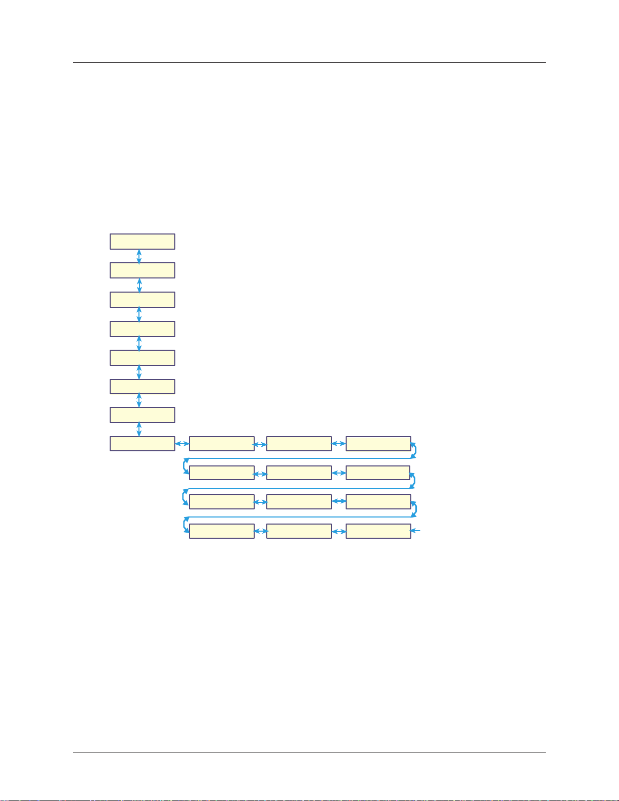
Using tUsing t
Using t
Using tUsing t
Status
Basic Options
Advanced
Options
Remote Config
Diagnostics
Phone Number
Memory
Caller ID
AA
A
AA
tt
ing ing
t
ing
tt
ing ing
––
VV
..
99
2 Only)2 Only)
–
V
.
9
2 Only)
––
VV
..
99
2 Only)2 Only)
• Using the LCD Panel to Set Your Country or Region Code
• Using the Global Wizard to Set Your Country or Region Code
• Using AT Commands to Set Your Country or Region Code
he Lhe L
he L
he Lhe L
CD P
1. Start at the Status LCD and use the down arrow to
move down the menu tree to the Region Select LCD.
2. Use the right arrow to move from the Region Select
LCD, across the Region Setting Options LCD, to the
Current Setting LCD.
3. If the current setting shown is not the one for your
region, arrow across to the Region Profile LCD. The
question mark represents the question Is this the region
you want? If B5 is the one you want, press Enter; if it s
not the one you want, arrow across until you see the code
you desire. See the list of Region Codes on the back of
this card.
4.When you reach the region code you want, press
Enter. After pressing Enter, you will see the message
Option Set
5. After setting the region profile, you can re-power the
modem or use the arrows to move back and up the menu
tree to return to the Status LCD.
CD PCD P
CD PCD P
.
YY
ourour
Y
our
YY
ourour
anel anel
anel
anel anel
C C
ountount
C
ount
C C
ountount
rr
r
rr
yy
y
yy
o o
o
o o
rr
r
rr
R R
R
R R
egeg
eg
egeg
ii
i
ii
oo
o
oo
n Cn C
n C
n Cn C
odod
od
odod
ee
e
ee
Region Select
Using tUsing t
Using t
Using tUsing t
The Global Wizard configuration utility is recommended for computers running in Windows. The
Wizard can configure your modem for a specific country or region with just a few mouse clicks.
1. Insert the MultiModemII CD into the CD-ROM drive. The Autorun dialog box appears.
2. Click Initial Setup and Country or Region Selection. The Global Wizard dialog box
appears. Click Next.
3. The Global Wizard searches for your modem and identifies it. Click Next after your modem is
identified.
4. Select the country or region in which the modem will be used. Click Next.
5. Review your choice. If it is correct, click Next to configure the modem.
6. When the Global Wizard announces that the parameters have been set, click Finish to exit.
Region Setting
Options B5?
Region Profile
99?
Region Profile
03?
Region Profile
09?
he Glohe Glo
he Glo
he Glohe Glo
bal bal
bal
bal bal
Current Setting
Region Profile
01? 02?
Region Profile
04?
Region Profile
6C? 9F?
WW
iziz
arar
W
WW
iz
iziz
ar
arar
dd
d
dd
Region Profile
Region Profile
Region Profile
00?
Region Profile
Multi-Tech Systems, Inc. MT5600BA/BL Series User Guide (S000276E)
10
Page 11

Chapter 2 - Installation
Using Using
Using
Using Using
If you are comfortable using AT commands, you can use them to configure your modem. You
must enter these commands in your communication program's terminal window. You can use a
communication program such as PhoneTools. See Step 4 below.
How to Change the Country/Region Code
1. View the list of available country/region codes to find your country/region code by
2. Set and save the code by executing the following command:
3. OK displays.
4. The code then displays.
How to Verify the Code
1. Type AT+GCI?<CR>
Example
1. Type AT+GCI=B5<CR> to set B5 as your country/region code.
2. Type AT+GCI?<CR> or ATI5<CR> to verify that B5 was set.
AA
TT
C C
oo
A
T
AA
TT
executing the command AT +GCI? <CR>
Note: A list of country/region codes is also available on the Multi-Tech Web site at:
http://www.multitech.com/PRODUCTS/Categories/Modems/global/
configuration.asp#chart
AT+GCI=
or you can use this command:
ATI5<CR>
B5 indicates the configuration is set for any B5 country such as Canada and the United
States.
mmmm
C
o
mm
C C
oo
mmmm
nn
<CR> (where
andsands
ands
andsands
nn
is the country/region code).
Step 4 - InstStep 4 - Inst
Step 4 - Inst
Step 4 - InstStep 4 - Inst
Note: PhoneTools may or may not be included on the MultiModemII CD according to your company's
preference.
Data communications software gives you access to commands that govern how the modem operates;
that is, how the modem handles incoming and outgoing data streams, etc.
MultiTech includes a data communications software package (PhoneTools) on the product CD shipped
with your modem. In general, the modem will work with most data communications software packages.
1. Insert the MultiModemII CD into your CD-ROM drive. Allow Autorun to bring up the introductory
screen.
2. Click on the PhoneTools icon and choose the appropriate language.
3. Follow the PhoneTools installation wizard. No input is needed. You may choose to view the
“Readme” file and whether or not to run PhoneTools immediately.
Windows NT/2000/XP Note: During installation, an advisory screen may appear saying “FAX
capture driver installation” - this may cause a delay in the installation. This is normal. The
installation process has not failed or stalled. Simply wait a few moments until this screen
disappears.
4. After installation, you can launch PhoneTools either from a desktop icon or from the Start |
Programs menu. Typically, it’s not necessary to reboot before using PhoneTools.
alal
l Phol Pho
al
l Pho
alal
l Phol Pho
neTneT
neT
neTneT
oooo
oo
oooo
ll
ss
l
s
ll
ss
Multi-Tech Systems, Inc. MT5600BA/BL Series User Guide (S000276E)
11
Page 12
Chapter 3 - Using the Front Panel
CC
hapterhapter
C
hapter
CC
hapterhapter
Like any modem, your Multi-Tech modem operates only under the control of a communication
program, such as the PhoneTools program included with the modem. It also operates under other
general-purpose data communication programs, such as Windows Terminal and HyperTerminal. For
information on how to use the modem with the communication program of your choice, please refer to the
program’s documentation.
3 - Using t 3 - Using t
3 - Using t
3 - Using t 3 - Using t
he Frhe Fr
he Fr
he Frhe Fr
oo
o
oo
ntnt
nt
ntnt
P P
anelanel
P
anel
P P
anelanel
ModMod
Mod
ModMod
Your modem normally is configured through Windows or through the communication program you are
using. The default settings work best for most purposes. See “Step 4: Install PhoneTools” in Chapter 2 for
help in setting up your communication program.
You also can configure your modem either through the front panel or by sending AT commands to the
modem. The AT commands can be found in the AT Reference Guide on the CD shipped with this
modem.
LED IndicatorsLED Indicators
LED Indicators
LED IndicatorsLED Indicators
The MT5600BA-V.92 has six LED indicators on the front panel that indicate status and activity:
em Cem C
em C
em Cem C
oo
nfnf
igig
urur
aa
tt
ii
oo
o
nf
ig
ur
oo
nfnf
igig
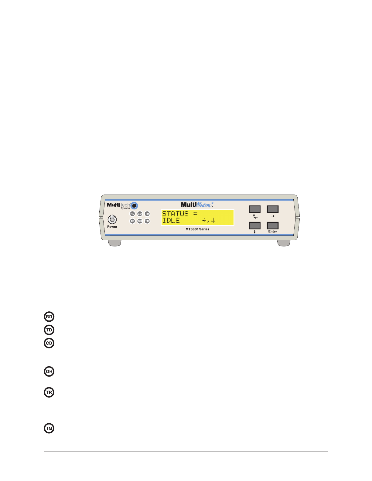
Figure 3-1. Front panel
urur
a
aa
t
tt
nn
i
o
n
ii
oo
nn
Receive Data. The RD indicator flashes when the modem is receiving data.
Transmit Data. The TD indicator flashes when the modem is transmitting data.
Carrier Detect. The CD indicator lights when the modem detects a valid carrier signal from
another modem. It is on when the modem is communicating with the other modem, and off when
the link is broken.
Off-Hook. The OH indicator lights when the modem is off-hook, which occurs when the
modem is dialing, online, or answering a call. The LED flashes when the modem pulse-dials.
Terminal Ready. The TR indicator lights when a communication program is using the
modem. It means the modem is ready for an outgoing or incoming call. It goes off when the
communication program disconnects the serial port. When it goes off, a connected modem will
disconnect.
Test Mode. The TM indicator lights when the modem is in test mode.
Multi-Tech Systems, Inc. MT5600BA/BL Series User Guide (S000276E)
12
Page 13

Chapter 3 - Using the Front Panel
Liquid CrLiquid Cr
Liquid Cr
Liquid CrLiquid Cr
The MultiModemII’s backlit liquid crystal display (LCD) has two functions: to display the current status of
the modem and to display configuration menus, which are selected using the four pushbuttons on the
front panel.
OptOpt
Opt
OptOpt
To select most configuration options, simply display the option in the LCD, and then press the Enter
button to select it. An OPTION SET message appears to confirm the selection. To exit the OPTION SET
message, press any button.
Some options, such as password options and phone number options, require you to enter a character
string. To select a character, press the
the
press the
Menu StMenu St
Menu St
Menu StMenu St
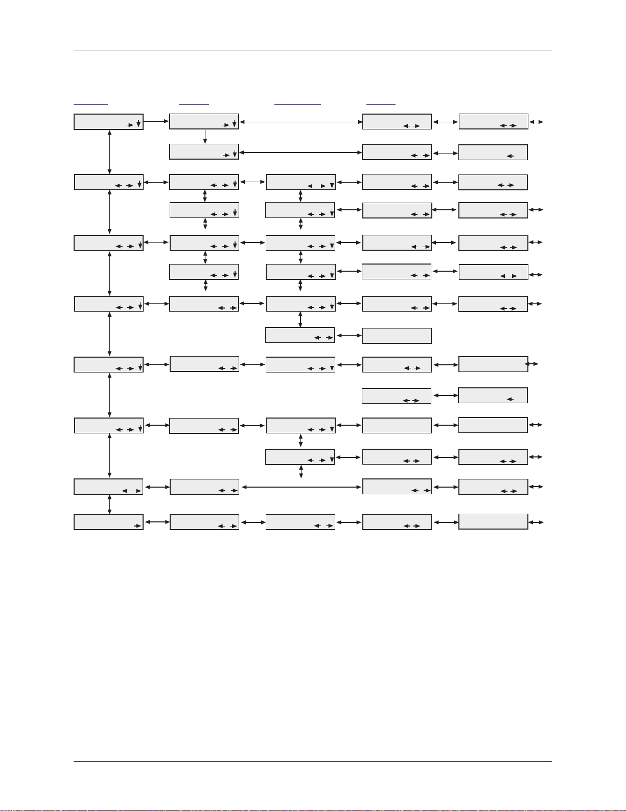
The LCD menus have a tree structure with multiple trunks, limbs, branches, and twigs. For a schematic
view, refer to the menu map on the next page.
Trunks are the major divisions of the menu tree. There are seven trunks: Status, Basic Options, Ad-
vanced Options, Remote Configuration, Diagnostics, Phone Number Memory, and Caller ID. Use the
and
ii
oo
n Selen Sele
i
o
n Sele
ii
oo
n Selen Sele
ÆÆ
Æ button. To backspace, press the
ÆÆ
ÆÆ
Æ button several times. To save a character string, press the Enter button.
ÆÆ
ÈÈ
È buttons to move between trunks.
ÈÈ
rr
uctuct
r
uct
rr
uctuct
yy
y
yy
ctct
ct
ctct
stst
al Dispal Disp
st
al Disp
stst
al Dispal Disp
ii
oo
nn
i
o
n
ii
oo
nn
urur
ee
ur
e
urur
ee
lala
yy
(L (L
la
y
lala
yy
ÇÇ
Ç
and
ÇÇ
ÅÅ
Å
ÅÅ
ÆÆ
Æ button before selecting a character. To exit without saving,
ÆÆ
CD)CD)
(L
CD)
(L (L
CD)CD)
ÈÈ
È buttons. To go to the next character position, press
ÈÈ
ÇÇ
Ç
ÇÇ
ÅÅ
Å
ÅÅ
Limbs are subdivisions of trunks. Use the
ÈÈ
and
È buttons to move between limbs on the trunk.
ÈÈ
Branches are subdivisions of limbs. Use the
ÇÇ
Ç
ÇÇ
ÅÅ
Å
ÅÅ
Twigs are status screens and options that are accessible only from branches. Use the
from a branch to its first status screen or option; then press the
options, and press the Enter button to select an option.
ÈÈ
and
È buttons to move between branches on the limb.
ÈÈ
ÆÆ
Æ button to move from a trunk onto its first limb, and the
ÆÆ
ÆÆ
Æ button to move from a limb onto its first branch, and the
ÆÆ
ÇÇ
Ç
ÇÇ
ÅÅ
Å
ÅÅ
ÈÈ
and
È buttons to move between
ÈÈ
ÇÇ
Ç
ÇÇ
ÅÅ
Å
ÅÅ
ÆÆ
Æ button to move
ÆÆ
Multi-Tech Systems, Inc. MT5600BA/BL Series User Guide (S000276E)
13
Page 14
Chapter 3 - Using the Front Panel
Menu OMenu O
Menu O
Menu OMenu O
vv
v
vv
erer
er
erer
vv
v
vv
ii
ee
ww
i
e
w
ii
ee
ww
Trunks Limbs Branches Twigs
Status =
Basic Options
Advanced Options
Remote
Config.
Diagnostics
,
,
,
,
,
, ,
,
,
,
Status =
Idle
Status =
Online
Online Options
Dialing Options
Remote Config.
Password
Diagnostic
Options
Phone Number
Mem. Ops.
Diagnostic
Options
( automatic selection )
,
,
,
,
,
,
,
,
,
, ,
,
Line Type
Options
Error Correction
Options
DTR Options
Carrier Detect
Options
Enable / Disable
R,C,
Remote Config.
Password
Analog Loopback
,
,
,
,
,
,
,
,
,
,
,
,
,
Manual Orig.?
Current Settings=
PSTN
Current Settings=
&E1
Current Settings=
&D2
Current Settings=
&C1 &C4
Current Settings=
Enabled
Enter Password
A
Initiate AL?
Ent
,
,
,
,
,
,
,
Ent
,
,
Manual Answer?
Disconnect?49333,Async,Lapm
PSTN?
EC on? (&E2)
DTR normal?
(&D2)
CD forced on?
(&C0)
Enable RC?
Test in Progress
Ent
,
,
Ent
,
Ent
,
,
Ent
,
,
Ent
,
,
Ent
,
,
Ent
,
,
Phone Number
Memory
Caller I.D. Caller I.D.
Region Select
,
,
,
Phone Number
Mem. Ops.
Options
Region Setting
Options
Initiate DL?
List Phone
,
, ,
,
Numbers
Enter Phone
Numbers
Current Setting =
02
,
,
,
,
,
Phone #0?
Enter Phone #0?
Region Setting
#CID0
Region Profile
XX?
,
,
,
Ent
,
Ent
,
Ent
,
Terminate RDL?
Phone #1?
Enter Phone #1?
Enable FCID?
(#CID1)
Region Profile
B5
Ent
,
Ent
,
,
Ent
,
,
Multi-Tech Systems, Inc. MT5600BA/BL Series User Guide (S000276E)
14
Page 15
Chapter 3 - Using the Front Panel
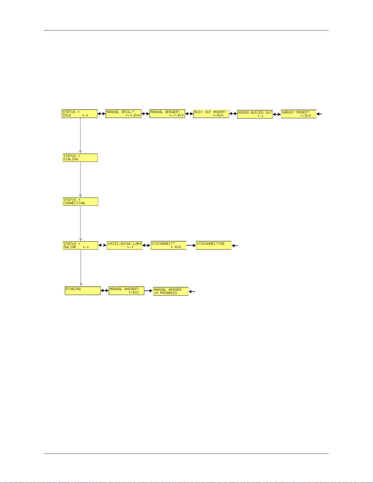
StSt
aa
tt
us us
TrTr
St
a
t
StSt
The Status Trunk shows the current operating status of the modem. Limb changes are automatic, but
certain options can be accessed by pressing the
the
type.
Limbs Twigs
If Idle
us
aa
tt
us us
ÆÆ
Æ button shows the connect status, including the data speed, connection type, and compression
ÆÆ
Tr
TrTr
unkunk
unk
unkunk
ÆÆ
Æ button. Note that when the modem is online, pressing
ÆÆ
If
Online
Multi-Tech Systems, Inc. MT5600BA/BL Series User Guide (S000276E)
15
Page 16
Chapter 3 - Using the Front Panel
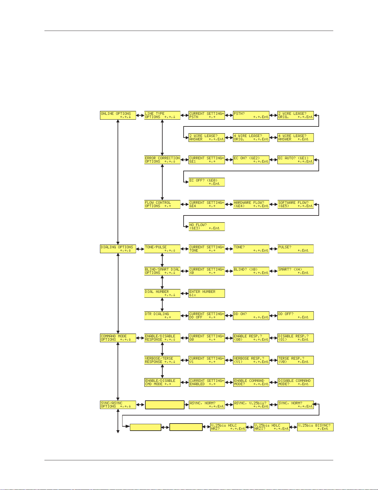
BB
asiasi
asi
asiasi
c Optc Opt
c Opt
c Optc Opt
B
BB
Use the Basic Options Trunk to configure the modem’s basic operating conditions. When entering a
number, use the
position, press the
ii
oo
ns ns
TrTr
i
o
ns
ii
oo
ns ns
ÇÇ
Ç
and
ÇÇ
ÅÅ
Å
ÅÅ
ÆÆ
Æ button. To back up or to exit without dialing, press the
ÆÆ
unkunk
Tr
unk
TrTr
unkunk
ÈÈ
È buttons to scroll through a list of digits and characters. To go to the next
ÈÈ
Limbs Branches Twigs
ÆÆ
Æ button several times.
ÆÆ
Current Setting
Async AT
Async, XCLK?
Continued on next page
Multi-Tech Systems, Inc. MT5600BA/BL Series User Guide (S000276E)
Async, SLAV?
16
Page 17

BB
B
BB
asiasi
asi
asiasi
c Optc Opt
c Opt
c Optc Opt
ii
oo
ns ns
TrTr
i
o
ns
ii
oo
ns ns
Continued from previous page
unkunk
Tr
unk
TrTr
unkunk
Limbs Branches Twigs
,,
,
c
,,
c c
c c
oo
o
oo
ntnt
inuedinued
nt
inued
ntnt
inuedinued
Chapter 3 - Using the Front Panel
Multi-Tech Systems, Inc. MT5600BA/BL Series User Guide (S000276E)
17
Page 18
Chapter 3 - Using the Front Panel
AA
dvdv
ancanc
anc
ancanc
ed Opted Opt
ed Opt
ed Opted Opt
A
dv
AA
dvdv
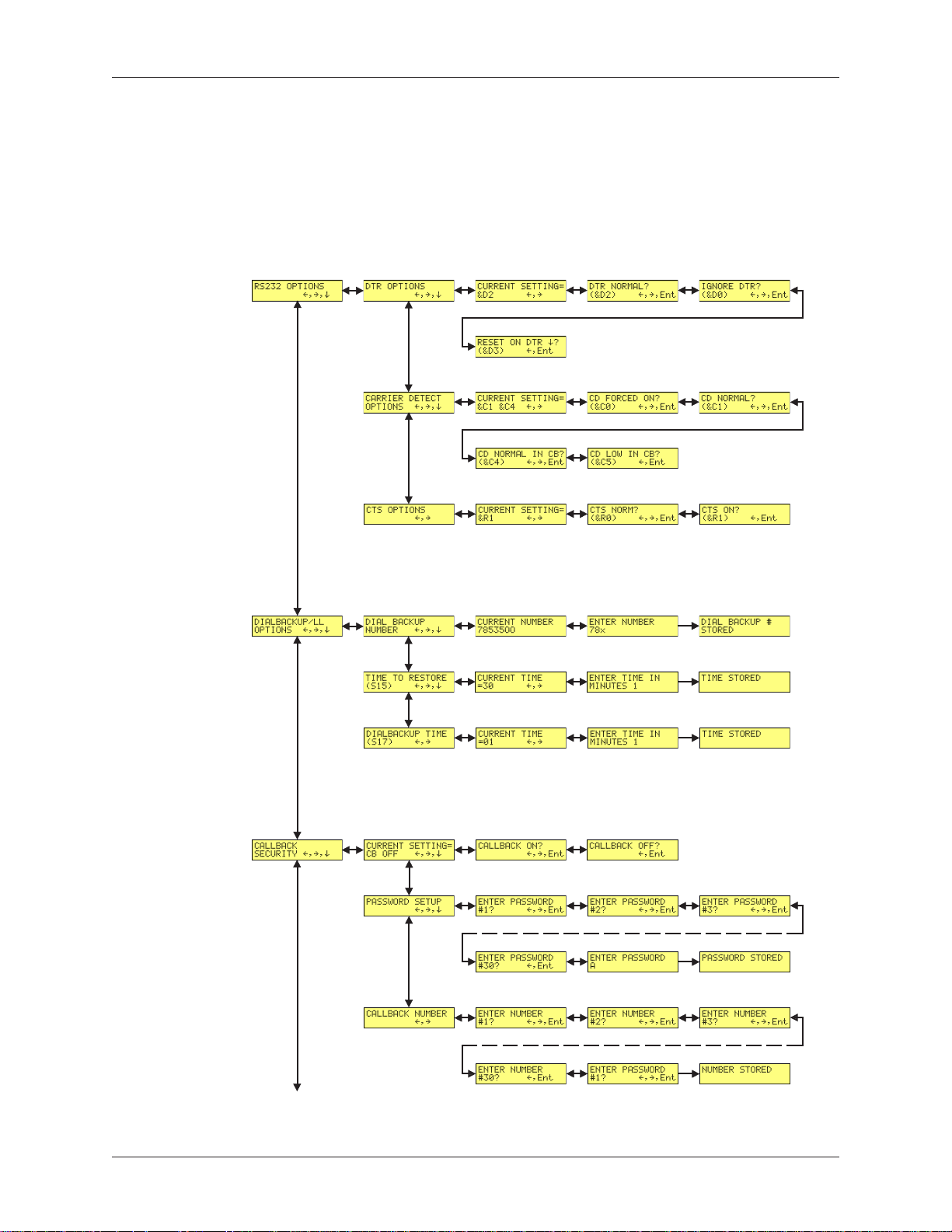
Use the Advanced Options Trunk to configure RS-232, dial backup, and callback security options. When
entering a number or password, use the
next position, press the
ii
oo
ns ns
TrTr
i
o
ns
ii
oo
ns ns
ÆÆ
Æ button. To backspace or to exit, press the
ÆÆ
Limbs Branches Twigs
Tr
TrTr
unkunk
unk
unkunk
ÇÇ
Ç
ÇÇ
ÅÅ
Å
ÅÅ
ÈÈ
and
È buttons to select a character or digit. To go to the
ÈÈ
ÆÆ
Æ button several times.
ÆÆ
Continued on next page
Multi-Tech Systems, Inc. MT5600BA/BL Series User Guide (S000276E)
18
Page 19
AA
A
AA
dvdv
dv
dvdv
ancanc
ed Opted Opt
anc
ed Opt
ancanc
ed Opted Opt
Continued from previous page
ii
oo
ns ns
i
o
ns
ii
oo
ns ns
Limbs Branches Twigs
TrTr
Tr
TrTr
unkunk
unk
unkunk
,,
c c
,
c
,,
c c
oo
o
oo
ntnt
inuedinued
nt
inued
ntnt
inuedinued
Chapter 3 - Using the Front Panel
Multi-Tech Systems, Inc. MT5600BA/BL Series User Guide (S000276E)
19
Page 20

Chapter 3 - Using the Front Panel
RR
emote Cemote C
R
emote C
RR
emote Cemote C
Use the Remote Configuration Options Trunk to enable or disable remote configuration on the modem,
and to change the password. When entering the password, use the
the alphabet. To go to the next character position, press the
ÆÆ
Æ button several times.
ÆÆ
oo
nfnf
igig
urur
aa
tt
ii
oo
o
nf
ig
ur
oo
nfnf
igig
Limb Branches Twigs
urur
a
aa
t
i
o
tt
ii
oo
n Optn Opt
n Opt
n Optn Opt
ii
oo
ns ns
TrTr
i
o
ns
ii
oo
ns ns
unkunk
Tr
unk
TrTr
unkunk
ÆÆ
Æ button. To backspace or to exit, press the
ÆÆ
ÇÇ
Ç
ÇÇ
ÅÅ
Å
ÅÅ
ÈÈ
and
È buttons to scroll through
ÈÈ
DiagDiag
Diag
DiagDiag
Use the Diagnostic Options Trunk to run loopback tests on the modem. When a test is in progress, the
TM indicator lights.
Note: Digital Loopback and Remote Digital Loopback tests must be performed using AT Commands. The
LCD option to run these tests has been temporarily removed.
nono
no
nono
stst
st
stst
ii
c Optc Opt
i
c Opt
ii
c Optc Opt
ii
oo
ns ns
TrTr
i
o
ns
ii
oo
ns ns
Limb Branches Twigs
Tr
TrTr
unkunk
unk
unkunk
Multi-Tech Systems, Inc. MT5600BA/BL Series User Guide (S000276E)
20
Page 21

Chapter 3 - Using the Front Panel
PhoPho
Pho
PhoPho
The MultiModemII can store up to four telephone numbers for speed dialing. Use the Phone Number
Memory Options Trunk to store, list, and dial these numbers. When entering a number, use the
ÈÈ
È buttons to scroll through the available digits and dialing commands. To go to the next position, press
ÈÈ
the
ne Numberne Number
ne Number
ne Numberne Number
ÆÆ
Æ button. To backspace or to exit, press the
ÆÆ
Memo Memo
Memo
Memo Memo
Limb Branches Twigs
rr
yy
r
y
rr
yy
Opt Opt
Opt
Opt Opt
ii
oo
ns ns
TrTr
i
o
ns
ii
oo
ns ns
ÆÆ
Æ button several times.
ÆÆ
Tr
TrTr
unkunk
unk
unkunk
ÇÇ
Ç
ÇÇ
ÅÅ
Å
ÅÅ
and
CalCal
lerler
Cal
CalCal
Use the Caller ID Options Trunk to enable or disable Caller ID operation.
Multi-Tech Systems, Inc. MT5600BA/BL Series User Guide (S000276E)
ID Opt ID Opt
ler
ID Opt
lerler
ID Opt ID Opt
ii
oo
ns ns
TrTr
i
o
ns
ii
oo
ns ns
Limb Branches Twigs
Note: See the overview drawing for setting country or region codes.
Tr
TrTr
unkunk
unk
unkunk
21
Page 22

Chapter 3 - Using the Front Panel
Menu OptMenu Opt
Menu Opt
Menu OptMenu Opt
This section describes important LCD screens and options. Many, but by no means all, of the options
have AT command equivalents.
StSt
aa
tt
a
aa
t
tt
usus
us
usus
St
StSt
Status screens display the current status of the modem. Though limb changes are automatic, certain
options can be selected by pressing the
ii
oo
nsns
i
o
ns
ii
oo
nsns
ÆÆ
Æ button.
ÆÆ
STATUS = IDLE. The modem is ready but inactive. This screen appears when the
modem is first turned on, and is the starting point for accessing all other screens.
Three options are available from this screen by pressing the
MANUAL ORIG.? Places the modem in originate mode for the
time specified by register S7. Use this option to connect to a
remote modem by manually dialing the number on a phone
connected to the local modem. When the remote modem answers,
press the Enter button to establish a connection with the remote
modem. You can also use this option to temporarily place the
modem in originate mode for back-to-back testing.
MANUAL ANSWER? Places the modem in answer mode for the
time specified by register S7. You can use this option to
temporarily place the modem in answer mode for back-to-back
testing.
ÆÆ
Æ button:
ÆÆ
BUSY OUT MODEM? Takes the modem out of service by putting
it into an off-hook state so that a calling modem receives a busy
signal.
MODEM BUSIED OUT. Shows that the modem is busied out. To
return the modem to normal service, press
STATUS = ONLINE. The modem is connected to another modem. Two options are
available from this screen by pressing the
Connect Status. Shows the connect speed, connection type,
and error correction being used.
DISCONNECT? Press the Enter button to force the modem to
hang up. Same as the ATH command.
RINGING. A remote modem or caller is attempting to establish a connection. One
option is available from this screen by pressing the
MANUAL ANSWER? Forces the modem to answer the phone.
You can use this option to establish a connection if autoanswer
is turned off (S0=0). Same as the ATA command.
ÆÆ
Æ button:
ÆÆ
ÆÆ
Æ button:
ÆÆ
ÆÆ
Æ, Enter.
ÆÆ
Multi-Tech Systems, Inc. MT5600BA/BL Series User Guide (S000276E)
22
Page 23

BB
B
BB
asiasi
asi
asiasi
c Optc Opt
c Opt
c Optc Opt
Chapter 3 - Using the Front Panel
ii
oo
nsns
i
o
ns
ii
oo
nsns
The following screens are used to configure the modem’s basic operating conditions.
ONLINE OPTIONS. The following screens are used to configure the online operation
of the modem:
LINE TYPE OPTIONS. Use the
from the following line types: dial-up (PSTN), two-wire leased
line originate or answer, and four-wire leased line originate or
answer.
ERROR CORRECTION OPTIONS. Use the
tons to turn error correction on or off, or to select automatic error
correction. Same as the &E0, &E1, and &
FLOW CONTROL OPTIONS. Use the
select no flow control, hardware flow control, or software flow
control. Same as the &E3, &E4, and &
DIALING OPTIONS. The following screens are used to configure dialing options or
to dial manually.
TONE/PULSE. Use the
DTMF tone dialing and pulse dialing. Same as the T and P commands.
BLIND/SMART DIAL OPTIONS. Use the
to select blind dialing, in which the modem sends the
NECT, RING, NO CARRIER, ERROR
sages to the computer and does not look for a dial tone or busy
signal, or smart dialing, in which the modem sends all messages
to the computer, including
the X0 and X4 commands.
ÆÆ
Æ and Enter buttons to select between
ÆÆ
ÆÆ
Æ and Enter buttons to select
ÆÆ
ÆÆ
Æ and Enter but-
ÆÆ
E2
commands.
ÆÆ
Æ and Enter buttons to
ÆÆ
E5
commands.
ÆÆ
Æ and Enter buttons
ÆÆ
and
NO ANSWER
NO DIALTONE
and
BUSY
OK, CON-
mes-
. Same as
DIAL NUMBER. Use the front panel buttons to enter a phone
number and dial it. To scroll through a list of digits and characters, press the
press the
ÆÆ
the
Æ button several times. To dial the number, press the Enter
ÆÆ
button. Same as the D command.
DTR DIALING. Use the
able DTR dialing. DTR dialing is popular in synchronous applications. In DTR dialing, the modem automatically dials the number
stored in memory location 0 when it detects a high DTR (Data
Terminal Ready) signal on the RS-232 interface. The DTR signal
must remain high for the duration of the call. To store the DTR
dialing number, use the &
#0 menu option.
Note: Plug and Play does not function if DTR dialing is enabled.
DTR is used during Plug and Play, and DTR dialing interferes
with it.
ÇÇ
Ç
ÇÇ
ÅÅ
Å
ÆÆ
Æ button. To back up or to exit without dialing, press
ÆÆ
ÅÅ
ÈÈ
and
È buttons. To go to the next position,
ÈÈ
ÆÆ
Æ and Enter buttons to enable or dis-
ÆÆ
Z0=
command or the ENTER PHONE
Multi-Tech Systems, Inc. MT5600BA/BL Series User Guide (S000276E)
23
Page 24

Chapter 3 - Using the Front Panel
COMMAND MODE OPTIONS. The following screens are used to configure result
code responses.
ENABLE/DISABLE RESPONSE. Use the
to enable or disable the sending of result codes to the computer.
Same as the
VERBOSE/TERSE RESPONSE. Use the
to select verbose or terse result codes. Same as the
commands.
ENABLE/DISABLE CMD MODE. Use the
to enable or disable the modem’s ability to accept AT commands
.
SYNC/ASYNC OPTIONS. Use the
transmission.
ASYNC, NORM? Normal asynchronous transmission using the
AT command set.
ASYNC, V.25bis? Asynchronous transmission using the V.25bis
command set.
SYNC, NORM? Normal synchronous transmission using any
command set.
V.25bis HDLC NRZ? V.25bis synchronous transmission using
NRZ encoding.
V.25bis HDLC NRZI? V.25bis synchronous transmission using
NRZI encoding.
ÆÆ
Æ and Enter buttons
ÆÆ
Q0
and
Q1
commands.
ÆÆ
Æ and Enter buttons
ÆÆ
V0
and
ÆÆ
Æ and Enter buttons
ÆÆ
ÆÆ
Æ and Enter buttons to select the method of data
ÆÆ
V1
V.25bis BISYNC? V.25bis bisynchronous transmission.
RESET FACTORY DEFAULTS. Use the
the modem’s active configuration to the factory defaults. Same as the AT&F&W
command string.
CONNECT RATE OPTIONS. Use the
serial port and data transmission speeds.
SERIAL BAUD RATE. Use the
the modem’s serial port speed. The valid range is 1200 to
115200 bps. Same as the
MODEM SPEED. Use the
modulation protocol to use in originating or answering a
connection. This also selects the maximum transmission speed
at which the modem can operate. Same as the +
command.
ÆÆ
Æ and Enter buttons to reset Profile 0 and
ÆÆ
ÆÆ
Æ and Enter buttons to change the modem’s
ÆÆ
ÆÆ
Æ and Enter buttons to select
ÆÆ
$SB
commands.
ÆÆ
Æ and Enter buttons to select the
ÆÆ
MS=[mod]
Multi-Tech Systems, Inc. MT5600BA/BL Series User Guide (S000276E)
24
Page 25

AA
A
AA
dvdv
dv
dvdv
ancanc
anc
ancanc
ed Opted Opt
ed Opt
ed Opted Opt
RS232 OPTIONS. The following screens are used to configure the RS-232 interface.
Chapter 3 - Using the Front Panel
ii
oo
nsns
i
o
ns
ii
oo
nsns
DTR OPTIONS. Use the
modem responds to the high to low transition of the DTR signal
sent by the computer. DTR NORMAL causes the modem to
hang up; IGNORE DTR allows operation with computers that do
not provide DTR; and RESET ON DTR
perform a soft reset as if the Z command were received. Same as
D0
the &
CARRIER DETECT OPTIONS. Use the
to select whether CD will be forced high (CD FORCED ON) or
whether it will go high when the remote modem’s carrier signal is
detected, and go low when the carrier signal is not detected (CD
NORMAL). Same as the &
callback security on UNIX systems, select CD LOW IN CB to
force CD low until the proper callback security password has
been entered or until a disconnect occurs. This prevents the
UNIX login prompt from being displayed before the callback se-
curity ENTER PASSWORD prompt appears. Select CD NOR-
MAL IN CB to disable this feature. Same as the &C5 and &
commands.
CTS OPTIONS. Use the
the CTS state will follow the RTS state when on line (CTS
NORM) or whether CTS will always be high (CTS ON). Same as
the &
, &D2, and &
R0
and &
R1
ÆÆ
Æ and Enter buttons to select how the
ÆÆ
ÈÈ
È causes the modem to
ÈÈ
D3
commands.
ÆÆ
Æ and Enter buttons
ÆÆ
C0
and &
C1
commands. When using
ÆÆ
Æ and Enter buttons to select whether
ÆÆ
commands.
C4
DIALBACKUP/LL OPTIONS. The following screens are used to configure dial back-
up for four-wire leased line operation. For more information, see Chapter 4, “Leased
Line Operation.”
DIAL BACKUP NUMBER. Use to enter a dial backup number.
To scroll through a list of digits and characters, press the
ÈÈ
and
È buttons. To go to the next position, press the
ÈÈ
To back up or to exit without saving, press the
times. To save the number, press the Enter button. Note: Only
16 characters can be displayed at a time. To see characters 17–30,
press the
button. To go to the next screen, press the
TIME TO RESTORE (S15). Sets how frequently leased line
restoral attempts occur when the modems are in dial backup
mode. The restore time interval can be set from 10 to 255 minutes in one minute increments. A value of 0 disables dial backup. Same as the
DIALBACKUP TIME (S17). Use to set how long the modem
waits after a leased line failure before it attempts a dial backup
connection. The timer can be set from 1 to 255 minutes in one
minute increments. Same as the
ÈÈ
È button. To go to the previous screen, press the
ÈÈ
S15=
command.
S17=
command.
ÆÆ
Æ button several
ÆÆ
ÆÆ
Æ button.
ÆÆ
ÇÇ
Ç
ÇÇ
ÅÅ
Å
ÅÅ
Å
ÅÅ
ÅÅ
ÆÆ
Æ button.
ÆÆ
Multi-Tech Systems, Inc. MT5600BA/BL Series User Guide (S000276E)
25
Page 26

Chapter 3 - Using the Front Panel
CALLBACK SECURITY. Use the
or off. Same as the
back security, see Chapter 6, “Callback Security.”
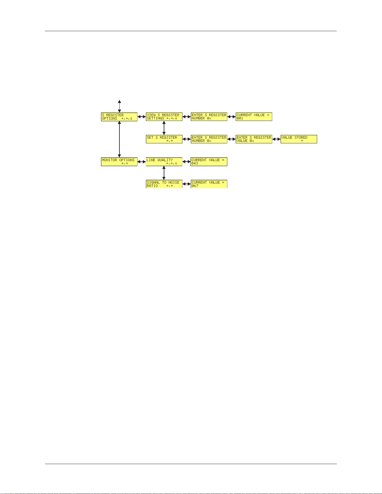
S-REGISTER OPTIONS. Use the
S-register values and enter new values. Same as the
#DB0
and
PASSWORD SETUP. Use to enter callback security passwords
in memory locations 1–30. Each password must be six to ten
characters in length. To scroll through a list of digits and characters, press the
press the
ÆÆ
the
Æ button several times. To save the password, press the
ÆÆ
Enter button. Same as the
CALLBACK NUMBER. Use to enter callback security phone
numbers in memory locations 1–30. Each number can be up to
30 characters long. Same as the
16 characters can be displayed at a time. To see characters 17–30,
press the
button. To go to the next screen, press the
VIEW S-REGISTER SETTINGS. Use the
buttons to select the number of the S-register whose value you
want displayed. To scroll through a list of digits, press the
ÈÈ
and
È buttons. To go to the next position, press the
ÈÈ
To back up or to exit without saving, press the
times. To display the value, press the Enter button. Same as
the
Sr?
ÆÆ
Æ and Enter buttons to turn callback security on
ÆÆ
#DB1
commands. For more information about call-
ÇÇ
Ç
ÇÇ
ÅÅ
Å
ÅÅ
ÆÆ
Æ button. To back up or to exit without saving, press
ÆÆ
ÈÈ
and
È buttons. To go to the next position,
ÈÈ
#CBP=
ÈÈ
È button. To go to the previous screen, press the
ÈÈ
ÆÆ
ÈÈ
Æ,
È, and Enter buttons to display the current
ÆÆ
ÈÈ
command.
command.
#CBN=
Sr?
command. Note: Only
and
ÆÆ
Æ button.
ÆÆ
Sr=n
commands.
ÆÆ
ÈÈ
ÇÇ
Æ,
È,
Ç
ÆÆ
ÈÈ
, and Enter
ÇÇ
ÅÅ
Å
ÅÅ
ÆÆ
Æ button.
ÆÆ
ÆÆ
Æ button several
ÆÆ
ÇÇ
Ç
ÇÇ
ÅÅ
Å
ÅÅ
ÅÅ
Å
ÅÅ
SET S-REGISTER. Use the
select the number of the S-register whose value you want to
change, and the value you want to enter. To scroll through a list
of digits, press the
tion, press the
press the
mand.
MONITOR OPTIONS. Use the
the line signal-to-noise ratio.
LINE QUALITY. Use the
signal quality as a three-digit number. The higher order byte of
the EQM value is displayed. Based on the EQM value, retrain or
fallback/fall forward may be initiated if enabled by
Same as the %Q command.
SIGNAL TO NOISE RATIO. Use the
display the line signal-to-noise ratio in dB.
ÆÆ
ÈÈ
È,
ÈÈ
ÇÇ
Ç
, and Enter buttons to
ÇÇ
ÅÅ
Å
ÅÅ
Sr=n
Æ,
ÆÆ
ÇÇ
Ç
ÇÇ
ÅÅ
Å
ÅÅ
ÆÆ
Æ button. To back up or to exit without saving,
ÆÆ
ÆÆ
Æ button several times. Same as the
ÆÆ
ÆÆ
ÈÈ
Æ,
È, and Enter buttons to display line quality and
ÆÆ
ÈÈ
ÈÈ
and
È buttons. To go to the next posi-
ÈÈ
ÆÆ
Æ and Enter buttons to display line
ÆÆ
%E1
ÆÆ
Æ and Enter buttons to
ÆÆ
com-
or
%E2
.
Multi-Tech Systems, Inc. MT5600BA/BL Series User Guide (S000276E)
26
Page 27

RR
emote Cemote C
R
emote C
RR
emote Cemote C
Chapter 3 - Using the Front Panel
oo
nfnf
igig
urur
aa
tt
ii
oo
o
nf
ig
ur
oo
nfnf
igig
The following screens are used to configure remote configuration options. For more
information about remote configuration, see Chapter 5, “Remote Configuration.”
urur
a
aa
t
i
o
tt
ii
oo
n Optn Opt
n Opt
n Optn Opt
ii
oo
nsns
i
o
ns
ii
oo
nsns
DiagDiag
Diag
DiagDiag
nono
no
nono
stst
st
stst
ENABLE/DISABLE R.C. Use the
remoteconfiguration on or off.
REMOTE CONFIG. PASSWORD. Use to enter the remote con-
figuration password. To scroll through a list of digits and characters, press the
press the
ÆÆ
the
Æ button several times. To save the password, press the
ÆÆ
Enter button.
ii
c Optc Opt
i
c Opt
ii
c Optc Opt
Use the following screens to turn loopback tests on and off.
ii
oo
nsns
i
o
ns
ii
oo
nsns
ANALOG LOOPBACK. Press the
the analog loopback test. The TEST IN PROGRESS screen
appears. To stop the test, press the
DIGITAL LOOPBACK. Press the
the local digital loopback test. The TEST IN PROGRESS
screen appears. To stop the test, press the
tons again. Same as the &
REMOTE DIGITAL LOOPBACK. Press the
tons to start the remote digital loopback test. The TEST IN
PROGRESS screen appears. To stop the test, press the
Enter buttons again. Same as the &
ÇÇ
Ç
ÇÇ
ÅÅ
Å
ÆÆ
Æ button. To back up or to exit without saving, press
ÆÆ
ÅÅ
ÈÈ
and
È buttons. To go to the next position,
ÈÈ
T3
command.
ÆÆ
Æ and Enter buttons to turn
ÆÆ
ÆÆ
Æ and Enter buttons to start
ÆÆ
ÆÆ
Æ and Enter buttons again.
ÆÆ
ÆÆ
Æ and Enter buttons to start
ÆÆ
ÆÆ
Æ and Enter but-
ÆÆ
ÆÆ
Æ and Enter but-
ÆÆ
ÆÆ
Æ and
ÆÆ
T6
command.
Note: Digital Loopback and Remote Digital Loopback tests must be performed using AT Commands. The
LCD option to run these tests has been temporarily removed.
PhoPho
Pho
PhoPho
ne Numberne Number
ne Number
ne Numberne Number
Memo Memo
Memo
Memo Memo
Use the following screens to list, enter, and dial stored phone numbers. Up to four
phone numbers can be stored. The number in memory location 0 is used for DTR
dialing, if DTR dialing is enabled. Note: Only 16 characters can be displayed at a time.
To display characters 17–30, press the
ÅÅ
the
Å button. To go to the next screen, press the
ÅÅ
rr
yy
Opt Opt
r
y
Opt
rr
yy
Opt Opt
LIST PHONE NUMBERS. Press the
display the phone number stored in each memory location.
ENTER PHONE NUMBERS. Use to store up to four phone num-
bers in memory locations 0–3. Each number can have up to 30
characters. To scroll through a list of digits and characters, press
the
button. To back up or to exit without saving, press the
several times. To save the number, press the Enter button.
Same as the &
DIAL STORED NUMBERS. Press the
dial a stored phone number. Same as the
ÇÇ
Ç
ÇÇ
ÅÅ
Å
ÅÅ
ii
oo
nsns
i
o
ns
ii
oo
nsns
ÈÈ
È button. To go to the previous screen, press
ÈÈ
ÆÆ
Æ button.
ÆÆ
ÆÆ
Æ button several times to
ÆÆ
ÈÈ
and
È buttons. To go to the next position, press the
ÈÈ
Z=
commands.
ÆÆ
Æ and Enter buttons to
ÆÆ
DS=
commands.
ÆÆ
Æ button
ÆÆ
ÆÆ
Æ
ÆÆ
Multi-Tech Systems, Inc. MT5600BA/BL Series User Guide (S000276E)
27
Page 28

Chapter 3 - Using the Front Panel
CalCal
Cal
CalCal
lerler
ID Opt ID Opt
ler
ID Opt
lerler
ID Opt ID Opt
ii
oo
nsns
i
o
ns
ii
oo
nsns
Press the
Caller ID, or to disable Caller ID altogether. Same as the
#CID=2
Note: Because Caller ID information is sent between the first and second ring,
register S0 must be set to 2 or more rings for the modem to receive Caller ID
information.
ÆÆ
Æ and Enter buttons to enable formatted (FCID) or unformatted (UCID)
ÆÆ
#CID=0, #CID=1
commands.
, and
Multi-Tech Systems, Inc. MT5600BA/BL Series User Guide (S000276E)
28
Page 29

Chapter 4 - Leased Line Operation
CC
hapterhapter
C
hapter
CC
hapterhapter
This chapter describes how to use the MultiModemII modem on a leased line.
A leased line is a private, permanent, telephone connection between two points. Unlike normal dialup
connections, a leased line is always active. The modems automatically connect when they are attached
to the line and are turned on
must be configured as the originate modem and the other as the answer modem; however, it does not
matter which is which.
In the event of an interruption, leased line modems automatically reconnect when the data line or power
is restored. The modem also supports dial backup, which enables the modem to automatically switch to a
dial-up connection if the leased line goes down.
The modem supports both two-wire and four-wire leased-line operation.
TT
ww
o-o-
WW
irir
T
TT
w
ww
o-
o-o-
W
WW
e Sete Set
ir
e Set
irir
e Sete Set
4 - L 4 - L
4 - L
4 - L 4 - L
. Because a leased line is always active, one of the two modems on the line
upup
up
upup
1. For two-wire leased line operation on the MT5600BA modem, connect the
provided modular telephone cable to the LINE jack. For two-wire leased line
operation on the MT5600BL modem, connect the provided modular telephone
cable to the LEASED jack. Connect the other end of the cable to the two-wire
leased line jack or terminals supplied by the telephone company.
ee
ased Line Operased Line Oper
e
ased Line Oper
ee
ased Line Operased Line Oper
aa
a
aa
tt
t
tt
ii
i
ii
oo
o
oo
nn
n
nn
2. Turn on the modem.
3. Starting at the STATUS screen, press the following buttons on the front panel:
ÈÈ
ÆÆ
ÈÈ
ÈÈ
ÈÈ
È,
Æ,
È,
ÈÈ
ÆÆ
ÈÈ
4. If the CURRENT SETTING= screen shows ASYNC AT, press
step 7. If it shows anything else, press
5. Press the Enter button to select normal asynchronous operation.
6. The OPTION SET screen appears. Press
OPTIONS screen.
7. Press
8. Choose one of two actions:
9. The OPTION SET screen appears. Press
ÇÇ
Ç
ÇÇ
ÅÅ
Å
appears.
• To set up the modem as the originate modem, press the Enter button.
• To set up the modem as the answer modem, press
Note: One of the modems in a leased line pair must be configured as the
originate modem, and the other as the answer modem, but it does not matter
which is which.
screen, or
ÅÅ
LEASE? ANSWER screen, and then press the Enter button.
ÆÆ
È,
È,
Æ. The CURRENT SETTING= screen appears.
ÈÈ
ÈÈ
ÆÆ
ÇÇ
Ç
and go to
ÇÇ
ÅÅ
Å
ÆÆ
Æ to go to the ASYNC, NORM? screen.
ÆÆ
ÇÇ
Ç
to exit to the SYNC/ASYNC
ÇÇ
ÅÅ
Å
ÅÅ
ÇÇ
ÇÇ
ÆÆ
ÆÆ
ÆÆ
,
Ç
,
Ç
,
Æ,
ÇÇ
ÇÇ
ÅÅ
ÅÅ
Å
Å
ÅÅ
ÅÅ
ÆÆ
Æ to exit to the CURRENT SETTING= screen to verify the selection.
ÆÆ
ÆÆ
Æ,
ÆÆ
ÆÆ
Æ,
Æ. The 2 WIRE LEASE? ORIG screen
ÆÆ
ÆÆ
ÆÆ
Æ to display the 2 WIRE
ÆÆ
ÇÇ
Ç
to exit to the ONLINE OPTIONS
ÇÇ
ÅÅ
Å
ÅÅ
ÅÅ
10. This completes the setup for two-wire leased line operation. Upon completion,
the modem attempts to connect to the modem at the other end of the leased line.
If the remote modem has not yet been configured for leased line operation, you
may turn off the local modem until the remote one is ready.
Multi-Tech Systems, Inc. MT5600BA/BL Series User Guide (S000276E)
29
Page 30

FF
our-our-
F
our-
FF
our-our-
WW
W
WW
Chapter 4 - Leased Line Operation
irir
e Sete Set
ir
e Set
irir
e Sete Set
1. For four-wire leased line operation, connect one of the provided four-wire cables
2. Turn on the modem.
3. Starting at the STATUS screen, press the following buttons on the front panel:
4. Press the Enter button to select normal synchronous operation.
upup
up
upup
to the LEASED jack on the back of the modem. Connect the other end of the
cable to a four-wire leased line jack or terminals supplied by the telephone
company.
ÈÈ
ÆÆ
ÈÈ
ÈÈ
ÈÈ
ÆÆ
ÆÆ
ÆÆ
È,
ÈÈ
Æ,
ÆÆ
È,
ÈÈ
È,
ÈÈ
È,
ÈÈ
Æ,
ÆÆ
Æ,
ÆÆ
ÆÆ
Æ,
Æ. The SYNC, NORM? screen appears.
ÆÆ
ÆÆ
5. The OPTION SET screen appears. Press
OPTIONS screen.
ÇÇ
ÇÇ
ÇÇ
ÆÆ
ÆÆ
ÆÆ
6. Press
7. Choose one of two actions:
8. The OPTION SET screen appears. Press
9. This completes the setup for four-wire leased line operation. Upon completion,
Ç
,
Ç
,
Ç
,
Æ,
ÇÇ
ÇÇ
ÅÅ
Å
appears.
• To set up the modem as the originate modem, press the Enter button.
• To set up the modem as the answer modem, press
Note: One of the modems in a leased line pair must be configured as the
originate modem, and the other as the answer modem, but it does not matter
which is which.
screen, or
the modem attempts to connect to the modem at the other end of the leased line.
If the remote modem has not yet been configured for leased line operation, you
may turn off the local modem until the remote one is ready.
ÅÅ
4 WIRE LEASE? ANSWER screen, and then press the Enter button.
ÇÇ
ÅÅ
ÅÅ
Å
Å
ÅÅ
ÅÅ
ÆÆ
Æ to exit to the CURRENT SETTING= screen.
ÆÆ
ÆÆ
Æ,
ÆÆ
Æ,
ÆÆ
ÆÆ
Æ,
ÆÆ
ÇÇ
Ç
to exit to the SYNC/ASYNC
ÇÇ
ÅÅ
Å
ÅÅ
ÆÆ
ÆÆ
Æ,
Æ. The 4 WIRE LEASE? ORIG screen
ÆÆ
ÆÆ
ÆÆ
Æ to display the
ÆÆ
ÇÇ
Ç
to exit to the ONLINE OPTIONS
ÇÇ
ÅÅ
Å
ÅÅ
Multi-Tech Systems, Inc. MT5600BA/BL Series User Guide (S000276E)
30
Page 31

Chapter 4 - Leased Line Operation
Dial BDial B
Dial B
Dial BDial B
For four-wire leased line operation, the MT5600BA-V.92 modem has a dial backup capability, in which
the modem is connected to a standard dial-up line as well as to the leased line. If the leased line fails, the
originate modem automatically dials and connects to the answer modem through the standard telephone
network. While it is in dial backup mode, the modem periodically checks the leased line to see if it is
operational. If the line is operational, the modem then attempts to restore the leased line. If the modem
detects that it is not connected to the standard telephone network when the leased line fails, it
immediately switches to leased line restoral.
The dial-back timer, register
it attempts a dial backup connection. The
originate modem tries to establish the leased line link. If the leased line is established during that time,
the
S17
backup connection. The purpose of the timer for the answer modem is to determine when it can accept a
dial-up call. Dial-back starts only when both timers have expired and the leased line is still down.
The restore timer, register
in dial backup mode.
disables dial backup. The default value is 30 minutes.
Note: Register
The dial backup number must be set from the front panel of the modem.
aa
cc
kup and Lkup and L
a
c
kup and L
aa
cc
kup and Lkup and L
S17
, determines how long the modem waits after a leased line failure before
timer is cleared and everything is back to normal. If the timer expires, the modem attempts a dial
S15
, determines how frequently restoral attempts occur when the modems are
S15
can be set from 10 to 255 minutes in one minute increments. A value of 0
S15
must be set identically on the local and remote modems.
ee
ased-Line Rased-Line R
e
ased-Line R
ee
ased-Line Rased-Line R
S17
default setting is one minute. During that minute, the
estoesto
esto
estoesto
rr
r
rr
alal
al
alal
Dial BDial B
Dial B
Dial BDial B
aa
cc
kup and Lkup and L
a
c
kup and L
aa
cc
kup and Lkup and L
1. Connect a modular telephone cable to the LINE jack of an MT5600BL modem set
up for four-wire leased line operation. Connect the other end of the cable to a
standard dialup line jack.
2. Turn on the modem.
3. Starting at the STATUS screen, press the following buttons on the front panel:
ÈÈ
ÈÈ
È,
È,
ÈÈ
ÈÈ
4. Press the
telephone number.
5. Press the
Note: To backspace or to cancel an entry, press
6. The number can be up to 30 characters in length. Repeat steps 4 and 5 until the
number is entered, and then press the Enter button to store it. The DIAL BACK-
UP # STORED screen appears.
7. Press the Enter button again to go to the DIAL BACKUP NUMBER screen.
Note: Steps 8 through 15 are optional.
ee
ased Line Rased Line R
e
ased Line R
ee
ased Line Rased Line R
ÆÆ
ÈÈ
ÆÆ
ÆÆ
Æ,
È,
Æ,
ÆÆ
ÈÈ
ÆÆ
ÇÇ
Ç
ÇÇ
ÅÅ
Å
ÅÅ
ÆÆ
Æ button to go to the next digit in the number.
ÆÆ
ÆÆ
Æ,
Æ. The ENTER NUMBER screen appears.
ÆÆ
ÆÆ
ÈÈ
or
È button several times to select the first digit in the dial backup
ÈÈ
estoesto
esto
estoesto
rr
al Setal Set
r
al Set
rr
al Setal Set
ÆÆ
Æ several times.
ÆÆ
upup
up
upup
Multi-Tech Systems, Inc. MT5600BA/BL Series User Guide (S000276E)
31
Page 32

Chapter 4 - Leased Line Operation
8. To change the default restore time, press
ÆÆ
(S15) screen, then press
pears.
9. Press the
10. Press the
11. Repeat steps 9 and 10 until you have entered a value between 10 and 255, or 0
to disable dial backup, and then press the Enter button to store it. The TIME
STORED screen appears.
12. Press the Enter button to return to the TIME TO RESTORE (S15) screen.
13. To change the default dial backup time, press
TIME (S17) screen, then press
appears.
14. Repeat steps 9 and 10 until you have entered a value between 0 and 255, and
then press the Enter button to store it. The TIME STORED screen appears.
15. Press the Enter button again to return to the DIAL BACKUP TIME (S17) screen.
16 . Dial backup and leased line restoral setup is complete.
Note: Registers
See the AT Command Reference Guide on the CD that was shipped with your
modem.
ÇÇ
Ç
ÇÇ
ÆÆ
Æ button to go to the next digit in the number.
ÆÆ
ÈÈ
or
È button several times to select the first digit in the number.
ÈÈ
ÅÅ
Å
ÅÅ
S15
and
S17
ÆÆ
Æ,
Æ. The ENTER TIME IN MINUTES screen ap-
ÆÆ
ÆÆ
ÆÆ
ÆÆ
Æ,
Æ. The ENTER TIME IN MINUTES screen
ÆÆ
ÆÆ
can also be changed using the
ÈÈ
È to go to the TIME TO RESTORE
ÈÈ
ÈÈ
È to go to the DIAL BACKUP
ÈÈ
Sr=n
AT command.
Note: The dial backup number can be displayed only 16 characters at a time. To see
characters 17–30, press the
button. To go to the next screen, press the
ÈÈ
È button. To go to the previous screen, press the
ÈÈ
ÆÆ
Æ button.
ÆÆ
ÅÅ
Å
ÅÅ
Multi-Tech Systems, Inc. MT5600BA/BL Series User Guide (S000276E)
32
Page 33

Chapter 5 - Remote Configuration
CC
hapterhapter
C
hapter
CC
hapterhapter
Remote configuration is a network management tool that allows you to configure modems anywhere in
your network from one location. With password-protected remote configuration, you can issue AT
commands to a remote MultiModemII modem for maintenance or troubleshooting as if you were on-site.
BB
asiasi
c Pc P
rr
B
asi
BB
The following steps are valid regardless of whether the connection is established by the local or the
remote MultiModemII modem.
1. Establish a data connection with a remote MT5600BA-V.92 modem.
2. Send three asterisks to initiate remote configuration. The remote modem responds:
3. Type the remote configuration password, and then press ENTER. The default is “MULTITECH.” It is
c P
asiasi
c Pc P
Online Remote Access
Remote password:
not case-sensitive.
• If the password is incorrect, the word CONNECT appears, and the local modem is returned to
online mode.
• If the password is correct, an >AT_ command prompt appears.
r
rr
ococ
oc
ococ
5 - R 5 - R
5 - R
5 - R 5 - R
eduredur
edur
eduredur
emote Cemote C
emote C
emote Cemote C
ee
e
ee
oo
o
oo
nfnf
nf
nfnf
igig
ig
igig
urur
ur
urur
aa
a
aa
tt
t
tt
i
ii
ii
oo
o
oo
nn
n
nn
4. Type AT commands to configure the remote modem. It is not necessary to precede the commands
with “AT.”
5. When you have finished configuring the remote modem, type *E and press ENTER to exit remote
configuration mode and return to online data mode. You can now break the connection in the normal
way.
Note: The dialing command is not allowed in remote configuration mode.
SetSet
Set
SetSet
Multi-Tech modems are shipped with a default setup password (MULTITECH). Because anyone who has
an owner’s manual knows the default setup password, for security you should change the password and
possibly also the remote configuration escape character.
CC
C
CC
PP
P
PP
The remote configuration password can be changed only from the front panel of the modem:
upup
up
upup
hanghang
hang
hanghang
asas
ss
s
ss
ww
w
ww
as
asas
ing ting t
ing t
ing ting t
oo
rr
dd
o
r
d
oo
rr
dd
1. Turn on the modem.
2. Starting at the STATUS screen, press
he Rhe R
he R
he Rhe R
PASSWORD screen.
emote Cemote C
emote C
emote Cemote C
oo
o
oo
nfnf
nf
nfnf
igig
ig
igig
ÈÈ
È
ÈÈ
urur
ur
urur
ÈÈ
È
ÈÈ
ÈÈ
È
ÈÈ
aa
a
aa
ÆÆ
Æ
ÆÆ
tt
ii
oo
nn
t
i
o
n
tt
ii
oo
nn
ÆÆ
ÈÈ
ÆÆ
Æ
È
Æ to access the ENTER
ÆÆ
ÈÈ
ÆÆ
Multi-Tech Systems, Inc. MT5600BA/BL Series User Guide (S000276E)
33
Page 34

Chapter 5 - Remote Configuration
3. To change the password, press
password, and then press
entered the entire password.
4. To cancel the new password, press
new password, press the Enter button. The next time you remotely configure the
modem you must use the new password.
CC
hanghang
C
hang
CC
hanghang
To improve security, you can change a remote modem’s remote configuration escape character. The
remote configuration escape character is stored in register
ASCII code for the asterisk character (*). Setting
but if you do this remotely, you won’t be able to change it back remotely!
ing ting t
ing t
ing ting t
he Rhe R
he R
he Rhe R
1. Establish a remote configuration link with the remote modem as described in
“Basic Procedure.”
2. Type ATS13=
escape character, and then press ENTER.
3. Save the new value by typing AT&W and pressing ENTER.
4. Type ATO<CR> to exit remote configuration.
emote Escemote Esc
emote Esc
emote Escemote Esc
S13
n
, where n is the ASCII code for the new remote configuration
ÇÇ
Ç
ÇÇ
ÆÆ
Æ to go to the next character. Repeat until you have
ÆÆ
to 0 (zero) disables remote configuration entirely—
ÈÈ
or
È to select the first character of the
ÈÈ
ÅÅ
Å
ÅÅ
ÆÆ
Æ until the password is erased. To save the
ÆÆ
ape Cape C
ape C
ape Cape C
S13
. The factory default is 42, which is the
harhar
har
harhar
aa
ctercter
a
cter
aa
ctercter
Multi-Tech Systems, Inc. MT5600BA/BL Series User Guide (S000276E)
34
Page 35

Chapter 6 - Callback Security
CC
hapterhapter
C
hapter
CC
hapterhapter
This chapter describes how to use callback security with your modem.
Callback security protects your network from unauthorized access and helps control long distance costs.
When callback security is enabled, all callers are requested to enter a password. If the password is
invalid, the caller can try twice more before the modem hangs up. If the password is valid, the modem
hangs up and returns the call by dialing the phone number associated with the password.
It is possible to implement password protection without callback by storing a hyphen (-) before the
callback phone number. The caller must then append a hyphen to his password to establish the direct
connection.
The modem can store up to 30 callback phone numbers and 30 callback passwords. Phone numbers can
be up to 30 characters long and can contain the pause (,) and wait (W) characters in addition to the digits
and characters normally found on a touch-tone keypad. Passwords can be up to 10 characters long.
Callback phone numbers are associated with callback passwords by being assigned to the same callback
memory location. For example, if you assign the password “APRICOT” to memory location 16 and, in a
separate operation, also assign phone number 6127853000 to memory location 16, the modem calls
phone number 6127853000 when it receives the password “APRICOT.”
6 - Cal 6 - Cal
6 - Cal
6 - Cal 6 - Cal
ll
baba
l
ba
ll
baba
cc
c
cc
kk
k
kk
Se Se
Se
Se Se
curcur
cur
curcur
itit
it
itit
yy
y
yy
Because there is no way to examine the passwords and phone numbers stored in the modem, it is
important to write them down as you enter them. A form that you can print out for this purpose is provided
on the last page of this chapter.
SetSet
Set
SetSet
TT
T
TT
Note: Autoanswer must be enabled (S0=1 or S0=2) for callback security to work.
AT Command MethodAT Command Method
AT Command Method
AT Command MethodAT Command Method
1. Open a terminal program, such as HyperTerminal.
2. In the terminal window, type one of the following commands:
up Pup P
up P
up Pup P
urur
ning Calning Cal
ur
ning Cal
urur
ning Calning Cal
• To turn on callback security, type AT#DB1 and press ENTER. With remote callback security
• To turn off callback security, type AT#DB0 and press ENTER. Callers no longer need a password
rr
ococ
oc
ococ
ll
baba
l
ba
ll
baba
eduredur
edur
eduredur
cc
kk
c
k
cc
kk
r
rr
turned on, each caller is asked to enter a password, then is disconnected and called back by
the modem. Also, dialing number locations 0–3, for use with the
replaced by callback dialing number locations 1–30.
to connect to the modem, the modem is unable to call them back, and stored dialing number
locations 0–3 become available.
Se Se
Se
Se Se
eses
es
eses
curcur
cur
curcur
itit
yy
On and O On and O
it
y
On and O
itit
yy
On and O On and O
ff
ff
f
f
ff
ff
DS=y
dialing command, are
Multi-Tech Systems, Inc. MT5600BA/BL Series User Guide (S000276E)
35
Page 36

FrFr
Fr
FrFr
AA
A
AA
oo
o
oo
ss
sigsig
s
sig
ss
sigsig
ntnt
P P
nt
ntnt
anel Metanel Met
P
anel Met
P P
anel Metanel Met
ning Calning Cal
ning Cal
ning Calning Cal
Chapter 6 - Callback Security
hodhod
hod
hodhod
1. Turn on the modem.
2. Starting at the STATUS screen, press the following buttons on the front panel to
turn callback security on and off:
ÈÈ
ÈÈ
ÆÆ
ÈÈ
ÈÈ
ÆÆ
• To turn on callback security, press
CALLBACK ON? option, and then press the Enter button to select the option.
When remote callback security is turned on, each caller is asked to enter a
password, then is disconnected and called back by the modem. Also, dialing
number locations 0–3, for use with the
by callback dialing number locations 1–30.
• To turn off callback security, press
CALLBACK OFF? option, and then press the Enter button to select the option.
Callers no longer need a password to connect to the modem, the modem is
unable to call them back, and stored dialing number locations 0–3 become
available.
ll
baba
cc
kk
P P
asas
ss
l
ba
ll
baba
c
cc
k
kk
P
P P
as
asas
s
ss
ww
w
ww
oo
o
oo
ÈÈ
È,
ÈÈ
rr
r
rr
È,
ÈÈ
DS=y
ÈÈ
È,
ÈÈ
dsds
ds
dsds
È,
Æ,
È,
ÈÈ
ÆÆ
ÆÆ
Æ,
ÆÆ
È,
ÈÈ
ÈÈ
dialing command, are replaced
ÈÈ
ÈÈ
È,
È,
ÈÈ
ÈÈ
ÆÆ
Æ,
Æ to display the
ÆÆ
ÆÆ
ÆÆ
ÆÆ
Æ,
ÆÆ
ÆÆ
Æ,
Æ to display the
ÆÆ
ÆÆ
AA
A
T
AA
FrFr
Fr
FrFr
TT
TT
C C
C
C C
oo
o
oo
oo
o
oo
ntnt
nt
ntnt
mmmm
mm
mmmm
P P
P
P P
and Metand Met
and Met
and Metand Met
1. Open a terminal program, such as HyperTerminal.
2. To store a callback password for the first callback memory location, type
3. To store a callback password for the second callback memory location, type
4. Repeat as many times as necessary, up to memory location 30, until all pass-
anel Metanel Met
anel Met
anel Metanel Met
1. Turn on the modem.
2. Starting at the STATUS screen, press the following buttons on the front panel:
3. Press the Enter button on the front panel to select callback memory location 1.
4. Press the
5. Press the
hodhod
hod
hodhod
AT#CBP01=
ENTER. The password must be six to ten characters in length.
AT#CBP02=
ENTER. Note that the memory location number in the command is incremented by
one.
words have been entered.
hodhod
hod
hodhod
ÈÈ
ÈÈ
È,
È,
ÈÈ
ÈÈ
The ENTER PASSWORD screen appears.
xxxxxxxxxx
xxxxxxxxxx
ÆÆ
ÈÈ
ÈÈ
Æ,
ÆÆ
ÆÆ
È,
È,
Æ,
ÈÈ
ÈÈ
ÆÆ
ÇÇ
Ç
ÇÇ
ÆÆ
Æ button to go to the next letter in the password.
ÆÆ
ÈÈ
or
È button several times to select the first letter in the password.
ÈÈ
ÅÅ
Å
ÅÅ
, where
, where
ÈÈ
ÆÆ
È,
Æ. The ENTER PASSWORD #1? screen appears.
ÈÈ
ÆÆ
xxxxxxxxxx
xxxxxxxxxx
is the first password, and press
is the second password, and press
Note: To backspace or to cancel an entry, press
6. The password must be six to ten characters in length. Repeat steps 4 and 5 until
the password is entered, and then press the Enter button to store it. The PASS-
WORD STORED screen should appear.
Multi-Tech Systems, Inc. MT5600BA/BL Series User Guide (S000276E)
ÆÆ
Æ several times.
ÆÆ
36
Page 37

7. Press the Enter button again to go to the PASSWORD SETUP screen.
8. Press
9. Repeat steps 3–7 to enter the next password.
10. Repeat as many times as necessary, up to memory location 30, until all
passwords have been entered.
Warning: There is no way to review an entry to confirm that it has been entered
correctly. If you attempt to look at a password entry by pressing the Enter button for
an ENTER PASSWORD #n? screen, it is possible to accidentally erase the entry.
AA
ss
sigsig
A
s
AA
ss
AT Command MethodAT Command Method
AT Command Method
AT Command MethodAT Command Method
ning Calning Cal
sig
ning Cal
sigsig
ning Calning Cal
ll
baba
cc
l
ba
c
ll
baba
cc
1. Open a data communication program, such as HyperTerminal.
2. To store a callback phone number in the first memory location, type
AT#CBN01=
The dialing string can include the digits 0 through 9 and any of the following
characters: #, *, comma (,), semicolon (;), W, A, B, C, and D. Up to 30 characters
can be used. Example: AT#CBN01=9,16127853000. If a direct connection with
password protection, but without hangup and callback, is desired, the first
character in the dialing string should be a hyphen (-).
Chapter 6 - Callback Security
ÆÆ
ÆÆ
Æ,
Æ to go to the ENTER PASSWORD #2? screen.
ÆÆ
ÆÆ
kk
Pho Pho
k
Pho
kk
Pho Pho
ne Numbersne Numbers
ne Numbers
ne Numbersne Numbers
xxxxxxxxxx
, where
xxxxxxxxxx
is the dialing string, and press ENTER.
3. To store a callback phone number in the second memory location, type
AT#CBN02=
Note that the memory location number in the command is incremented by one.
4. Repeat as many times as necessary, through memory location 30, until all
dialing strings have been entered.
Front Panel MethodFront Panel Method
Front Panel Method
Front Panel MethodFront Panel Method
1. Turn on the modem.
2. Starting at the STATUS screen, press the following buttons on the front panel:
ÈÈ
È,
ÈÈ
3. Press the Enter button on the front panel to select memory location 1. The
ENTER NUMBER screen appears.
4. Press the
connection, without hangup and callback, is desired, the first character in the
dialing string should be a hyphen (-).
5. Press the
Note: To backspace or to cancel an entry, press
6. The number can be up to 30 characters in length. Repeat steps 4 and 5 until the
number is entered, and then press the Enter button to store it. The NUMBER
STORED screen should appear.
ÈÈ
È,
ÈÈ
xxxxxxxxxx
ÆÆ
ÈÈ
ÈÈ
Æ,
ÆÆ
ÆÆ
È,
È,
Æ,
ÈÈ
ÈÈ
ÆÆ
ÇÇ
Ç
ÇÇ
ÆÆ
Æ button to go to the next character in the dialing string.
ÆÆ
ÈÈ
or
È button several times to select the first character. If a direct
ÈÈ
ÅÅ
Å
ÅÅ
ÈÈ
È,
ÈÈ
, where
ÈÈ
È,
ÈÈ
xxxxxxxxxx
ÆÆ
Æ. The ENTER NUMBER #1? screen appears.
ÆÆ
is the dialing string, and press ENTER.
ÆÆ
Æ several times.
ÆÆ
7. Press the Enter button again to go to the CALLBACK NUMBER screen.
Multi-Tech Systems, Inc. MT5600BA/BL Series User Guide (S000276E)
37
Page 38

Chapter 6 - Callback Security
ÆÆ
8. Press
9. Repeat steps 3–7 to enter the next number.
10. Repeat as many times as necessary, up to memory location 30, until all numbers
have been entered.
Warning: There is no way to review an entry to confirm that it has been entered
correctly. If you attempt to look at a number entry by pressing the Enter button for an
ENTER NUMBER #n? screen, it is possible for you to accidentally erase the entry.
ÆÆ
Æ,
Æ to go to the ENTER NUMBER #2? screen.
ÆÆ
ÆÆ
CalCal
Cal
CalCal
ling Pling P
ling P
ling Pling P
rr
ococ
r
rr
Use the following procedure to call a modem that has callback security enabled.
Note: Autoanswer must be enabled on the calling modem (S0=1 or S0=2).
Note: If you are calling a direct connect number, you must append a hyphen (-) to
the password. If the corresponding phone number has - as its first character, you will
be able to go directly online with the callback modem. If the corresponding phone
number has no - character, you will be prompted for a different password.
eduredur
oc
edur
ococ
eduredur
1. Using a data communication program such as HyperTerminal, dial the number of
the callback modem.
2. When the connection is established, the callback modem responds with a
request for a password.
3. Type the password for your modem, and then press ENTER. You have three
attempts to enter a valid password or be disconnected.
4. If the password is valid, the callback modem disconnects. Then, after a short
delay, it calls the number associated with the password and establishes a
working connection.
ee
e
ee
Multi-Tech Systems, Inc. MT5600BA/BL Series User Guide (S000276E)
38
Page 39

Chapter 6 - Callback Security
CalCal
Cal
CalCal
ll
baba
l
ba
ll
baba
cc
kk
Se Se
c
cc
k
kk
curcur
Se
cur
Se Se
curcur
The following AT commands are used with callback security.
Command: #DBnCallback Enable/Disable
Values:
Default: 0
Description: Enables or disables callback security. When callback security
Command: #CBNy=[-]xStore Callback Number
Values:
Default: None
Description: Stores the callback dialing string x in memory location y. The
itit
yy
C C
oo
it
y
C
itit
yy
C C
#DB0 Disables callback security.
#DB1 Enables callback security.
mmmm
o
mm
oo
mmmm
n
= 0 or 1
is enabled, phone number memory locations 0–4, used for
quick dialing and DTR dialing, become unavailable and are
replaced by callback security memory locations 1–30. The
phone number memory locations and their contents are
restored when callback security is disabled.
y
= 01–30
x
= dialing string
dialing string can include the digits 0 through 9 and any of the
following characters: #, *, comma (,), semicolon (;), W, A, B, C,
and D. Up to 30 characters can be used. Example:
AT#CBN01=9,16127853000. If the optional - character
precedes the dialing string, and the caller appends the same
character to the password, the caller is connected immediately,
and the hangup and callback are skipped.
andsands
ands
andsands
Command: #CBPy=xStore Callback Password
Values:
Defaults: None
Description: Stores callback security password x in memory location y. The
y
= 01–30
x
= password (6–10 characters)
password must have 6 to 10 characters.
Note: A direct connect password may not end with a hyphen (-).
Multi-Tech Systems, Inc. MT5600BA/BL Series User Guide (S000276E)
39
Page 40

Chapter 6 - Callback Security
CalCal
Cal
CalCal
LocationLocation
Location
LocationLocation
0101
01
0101
0202
02
0202
0303
03
0303
0404
04
0404
0505
05
0505
0606
06
0606
0707
07
0707
0808
08
0808
0808
08
0808
1010
10
1010
1111
11
1111
1212
12
1212
1313
13
1313
1414
14
1414
ll
baba
l
ba
ll
baba
cc
c
cc
kk
k
kk
AA
A
AA
ss
sigsig
s
sig
ss
sigsig
PasswordPassword
Password
PasswordPassword
nments Fnments F
nments F
nments Fnments F
oo
o
oo
rr
mm
r
m
rr
mm
Phone NumberPhone Number
Phone Number
Phone NumberPhone Number
1515
15
1515
1616
16
1616
1717
17
1717
1818
18
1818
1919
19
1919
2020
20
2020
2121
21
2121
2222
22
2222
2323
23
2323
2424
24
2424
2525
25
2525
2626
26
2626
2727
27
2727
2828
28
2828
2929
29
2929
3030
30
3030
Multi-Tech Systems, Inc. MT5600BA/BL Series User Guide (S000276E)
40
Page 41

Chapter 7 - Troubleshooting
CC
hapterhapter
C
hapter
CC
hapterhapter
Your modem was thoroughly tested at the factory before it was shipped. If you are unable to make a
successful connection, or if you experience data loss or garbled characters during your connection, it is
possible that the modem is defective. However, it is more likely that the source of your problem lies
elsewhere. The following symptoms are typical of problems you might encounter:
• None of the LEDs light when the modem is on.
• The modem does not respond to commands.
• The modem cannot connect when dialing.
• The modem disconnects while online.
• The modem cannot connect when answering.
• File transfer is slower than it should be.
• Data is being lost.
• There are garbage characters on the monitor.
• The modem doesn’t work with Caller ID.
• Fax and data software can’t run at the same time.
If you experience problems, please check the following possibilities before calling Technical Support (see
Appendix C).
7 - 7 -
7 -
7 - 7 -
TrTr
Tr
TrTr
ouboub
oub
ouboub
leshootleshoot
leshoot
leshootleshoot
inging
ing
inging
NoNo
ne ofne of
No
ne of
NoNo
ne ofne of
When you turn on the modem, the LED indicators on the front panel should flash briefly as the modem
runs a self-test, and the liquid crystal display (LCD) should light. If the LEDs and LCD remain off, the
modem is probably not receiving power.
• Make sure the modem’s power switch is on, especially if you normally turn the modem on by turning
on a power strip.
• If the modem is plugged into a power strip, make sure the power strip is plugged in and its power
switch is on.
• Make sure the transformer module is firmly connected to the modem and to the wall outlet or power
strip.
• If the power strip is on and the modem switch is on, try moving the transformer module to another
outlet on the power strip.
• Test that the outlet is live by plugging another device, such as a lamp, into it.
• The modem or transformer module may be defective. If you have another Multi-Tech modem, try
swapping modems. If the problem goes away, the first modem or transformer module may be
defective. Call Technical Support for assistance.
CAUTION: Do not under any circumstances replace the transformer module with one designed for
another product; doing so can damage the modem and void your warranty.
t t
he Indihe Indi
t
he Indi
t t
he Indihe Indi
cc
c
cc
aa
a
aa
toto
rs Lighrs Ligh
to
rs Ligh
toto
rs Lighrs Ligh
tt
t
tt
Multi-Tech Systems, Inc. MT5600BA/BL Series User Guide (S000276E)
41
Page 42

Chapter 7 - Troubleshooting
TT
he Modhe Mod
T
he Mod
TT
he Modhe Mod
• Make sure the modem is plugged in and turned on. (See “None of the Indicators Light.”)
• Make sure you are issuing the modem commands from data communication software, either
manually in terminal mode or automatically by configuring the software. (You cannot send
commands to the modem from the DOS prompt.)
• Make sure you are in terminal mode in your data communication program, then type AT and press
ENTER. If you get an OK response from your modem, your connections are good and the problem
likely is in the connection setup in your communication software.
• Try resetting your modem by turning it off and on. If you are using DOS or Windows 3.1
communication software, make sure the initialization string includes &F as the first command, to
cancel any “leftover’ command that could affect the modem’s operation.
• If you don’t get an OK, the problem may still be in the communication software. Make sure you have
done whatever is necessary in your software to make a port connection. Not all communication
programs connect to the COM port automatically. Some connect when the software loads and
remain connected until the program terminates. Others can disconnect without exiting the program.
The modem’s TR indicator lights to show that the software has taken control of the modem through
the COM port.
em Dem D
em D
em Dem D
oes Notoes Not
oes Not
oes Notoes Not
R R
espoespo
R
espo
R R
espoespo
nd to Cnd to C
nd to C
nd to Cnd to C
oo
mmmm
o
mm
oo
mmmm
andsands
ands
andsands
• Your communication software settings may not match the physical port the modem is connected to.
The serial cable might be plugged into the wrong connector—check your computer documentation
to make sure. Or you might have selected a COM port in your software other than the one the
modem is physically connected to—compare the settings in your software to the physical
connection.
• If the modem is on, the cable is plugged into the correct port, the communication software is
configured correctly, and you still don’t get an OK, the fault might be in the serial cable. Make sure it
is firmly connected at both ends.
• Is this the first time you have used the cable? If so, it may not be wired correctly. Check the cable
description on the packaging to make sure the cable is the right one for your computer.
• Peripheral expansion cards, such as sound and game cards, might include a serial port
preconfigured as COM1 or COM2. The extra serial port, or the card itself, may use the same COM
port, memory address, or interrupt request (IRQ) as your communication port. Be sure to disable
any unused ports.
Windows 3.1x: To look for address or IRQ conflicts, in Program Manager select File | Run, type
MSD, and press ENTER. Then select Mouse, COM Ports, and IRQ Status, and note the addresses
and IRQs that are in use. If you find an IRQ conflict, note which IRQs are not being used, then
change one of the conflicting devices to use one of the unused IRQs. If you find an address conflict,
change the address of one of the conflicting devices.
To change a port address or IRQ in Windows 3.1x, double-click the Control Panel icon, then the
Ports icon. Click on the port you want to change, click Settings, click Advanced, and select the
new port address and/or interrupt. If you wish to use COM3 or COM4, note that COM3 shares an
IRQ with COM1, as does COM4 with COM2, so you should change their IRQs to unused ones, if
possible.
Multi-Tech Systems, Inc. MT5600BA/BL Series User Guide (S000276E)
42
Page 43

Chapter 7 - Troubleshooting
Windows 9x: Right-click on My Computer, select Properties from the menu, click on the Device
Manager tab, double-click on Ports, then double-click on the communication port your modem is
connected to. In the port’s Properties sheet, click on the Resources tab to see the port’s input/
output range and interrupt request. If another device is using the same address range or IRQ, it
appears in the Conflicting Device List. Uncheck Use automatic settings to change the port’s
settings so they do not conflict with the other device, or select the port the conflicting device is on
and change it instead. If you need to open your computer to change switches or jumpers on the
conflicting device; refer to the device’s documentation.
Windows NT 4.0: To look for address or IRQ conflicts, click Start, Programs, Administrative Tools
(Common), and Windows NT Diagnostics. In the Windows NT Diagnostics dialog box, click the
Resources tab to see which input/output ranges and interrupt requests are in use. If you need to
open your computer to change switches or jumpers on the conflicting device; refer to the device’s
documentation.
••
• The serial port might be defective. If you have another serial port, install the modem on it, change
••
the COM port setting in your software, and try again.
••
• The modem might have a problem beyond the scope of this user guide. If you have another Multi-
••
Tech modem, try swapping modems. If the problem goes away, call Technical Support for
assistance (see Appendix D).
TT
he Modhe Mod
T
he Mod
TT
he Modhe Mod
There can be several reasons the modem fails to make a connection. Possibilities include:
• lack of a physical connection to the telephone line.
• a wrong dial tone.
• a busy signal.
• a wrong number.
• no modem at the other end.
• a faulty modem, computer, or software at the other end.
• incompatibility between modems.
You can narrow the list of possibilities by using extended result codes. Extended result codes are
enabled by default. If they have been disabled, include V1X4 in the modem’s initialization string, or in
terminal mode enter ATV1X4 and press ENTER. When you dial again, the modem reports the call’s
progress.
• If the modem reports
both the modem’s LINE jack (not the PHONE jack) and the telephone wall jack. If the cable looks
secure, try replacing it. If that doesn’t work, the problem might be in your building’s telephone
installation. To test the building installation, plug a telephone into your modem’s telephone wall jack
and listen for a dial tone. If you hear a dial tone, your modem might be installed behind a corporate
phone system (PBX) with an internal dial tone that sounds different from the normal dial tone. In
that case, the modem might not recognize the dial tone and might treat it as an error. Check your
PBX manual to see if you can change the internal dial tone; if you can’t, change your modem’s
initialization string to replace X4 with X3, which will cause the modem to ignore dial tones (note,
however, that X3 is not allowed in some countries, such as France and Spain).
em Cannotem Cannot
em Cannot
em Cannotem Cannot
NO DIALTONE
, check that the modem’s telephone line cable is connected to
C C
C
C C
oo
nnenne
o
nne
oo
nnenne
ctct
ct
ctct
WW
hen Dialinghen Dialing
W
hen Dialing
WW
hen Dialinghen Dialing
Multi-Tech Systems, Inc. MT5600BA/BL Series User Guide (S000276E)
43
Page 44

Chapter 7 - Troubleshooting
• If the modem reports BUSY, the other number might be busy, in which case you should try again
later, or it might indicate that you have failed to add a 9, prefix to the phone number if you must dial
9
for an outside line.
If you must dial 9 to get an outside line, the easiest way to dial it automatically is to include it in the
modem’s dial prefix, e.g., ATDT9,. Note the comma, which inserts a pause before the number is
dialed. By inserting 9, into the dial prefix, you do not have to include it in each directory entry.
To change the dial prefix in Windows 95 HyperTerminal, select Connect from the Call menu, click
Dialing Properties, and type 9 in the local and long distance boxes in How I dial from this
location.
• If the modem reports
dialed a wrong number. Check the number.
• If the modem reports
was made. You might have dialed a wrong number, and a person answered instead of a computer,
or you might have dialed the correct number but the other computer or software was turned off or
faulty. Check the number and try again, or try calling another system to make sure your modem is
working. Also, try calling the number on your telephone. If you hear harsh sounds, then another
modem is answering the call, and the modems might be having problems negotiating because of
modem incompatibilities or line noise. Try connecting at a lower speed.
TT
he Modhe Mod
T
he Mod
TT
he Modhe Mod
• If you have Call Waiting on the same phone line as your modem, it can interrupt your connection
when someone tries to call you. If you have Call Waiting, disable it before each call. In most
telephone areas in North America, you can disable Call Waiting by preceding the telephone number
with *70 (check with your local telephone company).
You can automatically disable Call Waiting by including the disabling code in the modem’s dial
prefix (e.g., ATDT*70,—note the comma, which inserts a pause before the number is dialed). To
change the dial prefix in Windows Terminal, select Settings | Modem Commands. To change it in
HyperTerminal, select Connect from the Call menu, click Dialing Properties, check This location
has Call Waiting, and select the correct code for your phone service.
• If you have extension phones on the same line as your modem, you or someone else can interrupt
the connection by picking up another phone. If this is a frequent problem, disconnect the extension
phones before using the modem, or install another phone line especially for the modem.
em Discem Disc
em Disc
em Discem Disc
NO ANSWER
NO CARRIER
oo
o
oo
, the other system has failed to go off-hook, or you might have
, the phone was answered at the other end, but no connection
nnenne
nne
nnenne
cts cts
cts
cts cts
WW
hile Onlinehile Online
W
hile Online
WW
hile Onlinehile Online
• Check for loose connections between the modem and the computer, the telephone jack, and AC
power.
• You might have had a poor connection because of line conditions or the problem might have
originated on the other end of the line. Try again.
• If you were online, it might have hung up on you because of lack of activity on your part or because
you exceeded your time limit for the day. Try again.
Multi-Tech Systems, Inc. MT5600BA/BL Series User Guide (S000276E)
44
Page 45

TT
he Modhe Mod
T
he Mod
TT
he Modhe Mod
em Cannotem Cannot
em Cannot
em Cannotem Cannot
C C
C
C C
oo
nnenne
o
nne
oo
nnenne
ctct
ct
ctct
WW
W
WW
Chapter 7 - Troubleshooting
henhen
hen
henhen
AnsAns
Ans
AnsAns
• The default DTR Control command (&D2) inhibits autoanswer. To enable autoanswer, change DTR
• Autoanswer might be disabled. Turn on autoanswer in your datacomm program or send the
File File
File
File File
• You might have an older UART. For best throughput, install a 16550AFN UART or a Multi-Tech ISI
• If you are running under Windows 3.1 and have a 16550AFN UART, you must replace the
• If you are using a slow transfer protocol, such as Xmodem, try Zmodem or Ymodem/G instead.
• Is your line noisy? If there is static on your line, the modem has to resend many blocks of data to
• Are you downloading a compressed file with MNP 5 hardware compression enabled? Since
ww
erer
w
ww
Control to &D0, and make sure &Q0, &Q1, &Q5, or &Q6 is also set. For more information, see the
&D command in the AT Command Reference Guide on the CD shipped with your modem. For
information on changing the modem’s default configuration, see “Step 3: Install and Configure Your
Software” in Chapter 2.
command ATS0=1 (ATS0=2 if you have Caller ID service) to your modem in terminal mode.
TrTr
Tr
TrTr
serial port card.
Windows serial driver, COMM.DRV, to take full advantage of the UART’s speed.
insure accuracy. You must have a clean line for maximum speed.
hardware data compression cannot compress a file already compressed by an archiving program, the
transfer can be marginally slower with data compression enabled than with it disabled.
inging
er
ing
erer
inging
ansfansf
ansf
ansfansf
erer
Is Slo Is Slo
er
Is Slo
erer
Is Slo Is Slo
ww
w
ww
erer
er
erer
TT
han Ihan I
T
han I
TT
han Ihan I
tt
Should Be Should Be
t
Should Be
tt
Should Be Should Be
• Does your Internet service provider (ISP) use the same 56K protocol as your modem? The default
setting of your modem is to connect using either the 56K or the V.90 protocol, depending on which
one the ISP modem is using. If your ISP uses the X2 protocol, the maximum speed you will be able
to connect at is 33,600 bps. Check with your ISP to see which protocols it supports, and check the
Multi-Tech Web site for the latest developments in V.92.
• Try entering the &V1 command to display information about the last connection, making a screen
print of the connection statistics, and checking for parameters that might be unacceptable.
DD
aa
tt
D
DD
• If you are using data compression and a high speed serial port, set the serial port baud rate to four
• Your UART might not be reliable at serial port speeds over 9600 bps or 19,200 bps. Turn off data
• Make sure the flow control method you selected in software matches the method selected in the
• Try entering the &V1 command to display information about the last connection, making a screen
a Is Being Loa Is Being Lo
a
t
a Is Being Lo
aa
tt
a Is Being Loa Is Being Lo
times the data rate.
compression, reset your serial port speed to a lower rate, or replace your serial port with a faster
one.
modem. If you are using the modem with a Macintosh, you might have the wrong cable for
hardware flow control.
print of the connection statistics, and checking for parameters that might be unacceptable.
stst
st
stst
Multi-Tech Systems, Inc. MT5600BA/BL Series User Guide (S000276E)
45
Page 46

Chapter 7 - Troubleshooting
TT
herher
T
her
TT
herher
• Your computer and the remote computer might be set to different word lengths, stop bits, or
• You might be experiencing line noise. Enable error correction, if it is disabled, or hang up and call
• At speeds above 2400 bps, the remote modem might not use the same transmission or error
• Try entering the &V1 command to display information about the last connection, making a screen
TT
he Modhe Mod
T
he Mod
TT
he Modhe Mod
• Caller ID information is transmitted between the first and second rings, so if autoanswer is
e e
ArAr
Ar
ArAr
e Ge G
e G
e Ge G
em Dem D
em D
em Dem D
e
e e
parities. If you have connected at 8-N-1, try changing to 7-E-1, or vice-versa, using your
communication software.
again; you might get a better connection the second time.
correction standards as your modem. Try connecting at a slower speed or disabling error
correction. (With no error correction, however, line noise can cause garbage characters.)
print of the connection statistics, and checking for parameters that might be unacceptable.
turned off (S0=0) or if the modem is set to answer after only one ring (S0=1), the modem will not
receive Caller ID information. Check your initialization string, and if necessary change it to set the
modem to answer after the second ring (S0=2).
arbagarbag
arbag
arbagarbag
oesnoesn
oesn
oesnoesn
e Ce C
e C
e Ce C
’’
tt
’
t
’’
tt
harhar
har
harhar
WW
oo
W
o
WW
oo
aa
cters octers o
a
cters o
aa
cters octers o
rkrk
ww
rk
w
rkrk
ww
itit
h Calh Cal
it
h Cal
itit
h Calh Cal
n tn t
n t
n tn t
lerler
ler
lerler
he Mohe Mo
he Mo
he Mohe Mo
ID ID
ID
ID ID
nitonito
nito
nitonito
rr
r
rr
• Make sure that you have Caller ID service from your telephone company.
FF
axax
F
FF
• Communication devices can be accessed by only one application at a time. Under DOS or
and D and D
ax
and D
axax
and D and D
TT
imeime
T
ime
TT
imeime
Windows 3.1x, you can run either your fax software or your datacomm software, but not both at
the same time, unless you have a special communication device management application. In
Windows 95, 98, and NT 4.0, you can have data and fax communication applications open at the
same time, but they cannot use the same modem at the same time.
aa
tt
a Sofa Sof
a
t
a Sof
aa
tt
a Sofa Sof
tt
t
tt
ww
w
ww
arar
e Cane Can
ar
e Can
arar
e Cane Can
’’
tt
Run a Run a
’
t
Run a
’’
tt
Run a Run a
t
tt
tt
t t
t
t t
he She S
he S
he She S
ameame
ame
ameame
Multi-Tech Systems, Inc. MT5600BA/BL Series User Guide (S000276E)
46
Page 47

Appendix A - Regulatory Compliance
AppendixAppendix
Appendix
AppendixAppendix
CC
oo
C
o
CC
oo
FF
CC
C PC P
arar
tt
F
C
C P
FF
CC
1. This equipment complies with part 68 of the Federal Communications Commission Rules. On the
2. The suitable USOC jack (Universal Service Order Code connecting arrangement) for this equipment
3. An FCC-compliant telephone cord and modular plug is provided with this equipment. This
4. The ringer equivalence number (REN) is used to determine the number of devices that may be
5. If this equipment causes harm to the telephone network, the telephone company will notify you in
6. The telephone company may make changes in its facilities, equipment, operations, or procedures
7. If trouble is experienced with this equipment (the model of which is indicated below) please contact
8. No repairs are to be made by you. Repairs are to be made only by Multi-Tech Systems or its
9. This equipment should not be used on party lines or coin lines.
10. If so required, this equipment is hearing-aid compatible.
11. Manufacturing Information:
ar
C PC P
arar
outside surface of this equipment is a label that contains, among other information, the FCC
registration number. This information must be provided to the telephone company.
is shown below. If applicable, the facility interface codes (FIC) and service order codes (SOC) are
shown.
equipment is designed to be connected to the telephone network or premises wiring using a
compatible modular jack that is Part 68 compliant. See installation instructions for details.
connected to the telephone line. Excessive RENs on the telephone line may result in the device not
ringing in response to an incoming call. In most, but not all, areas the sum of the RENs should not
exceed 5.0. To be certain of the number of devices that may be connected to the line, as
determined by the total RENs, contact the local telephone company.
advance that temporary discontinuance of service may be required. But if advance notice is not
practical, the telephone company will notify you as soon as possible. Also, you will be advised of
your right to file a complaint with the FCC if you believe it is necessary.
that could affect the operation of the equipment. If this happens, the telephone company will provide
advance notice in order for you to make necessary modifications in order to maintain uninterrupted
service.
Multi-Tech Systems, Inc. at the address shown below for details of how to have repairs made. If the
trouble is causing harm to the telephone network, the telephone company may request you remove
the equipment from the network until the problem is resolved.
licensees. Unauthorized repairs void registration and warranty.
68 68
t
68
tt
68 68
TT
eleele
cc
T
ele
TT
eleele
Manufacturer: Multi-Tech Systems, Inc.
Trade Name MultiModemII
Model Number: MT5600BA
FCC Registration No: AU7USA-33378-M5-E
Ringer Equivalence No: 0.1A
Modular Jack (USOC): RJ11C or RJ11W (single line)
Service Center in USA: Multi-Tech Systems, Inc.
c
cc
oo
o
oo
AA
A
AA
mpmp
mp
mpmp
mm
m
mm
- R - R
- R
- R - R
2205 Woodale Drive
Mounds View, MN 55112
U.S.A.
(763) 785-3500
(763) 785-9874 Fax
egeg
eg
egeg
lianclianc
lianc
lianclianc
ulaula
ula
ulaula
ee
e
ee
toto
to
toto
rr
r
rr
yy
y
yy
Multi-Tech Systems, Inc. MT5600BA/BL Series User Guide (S000276E)
47
Page 48

Appendix A - Regulatory Compliance
FF
axax
Br Br
F
ax
FF
axax
The Telephone Consumer Protection Act of 1991 makes it unlawful for any person to use a computer or
other electronic device, including fax machines, to send any message unless such message clearly
contains the following information:
• Date and time the message is sent
• Identification of the business or other entity, or other individual sending the message
• Telephone number of the sending machine or such business, other entity, or individual
This information is to appear in a margin at the top or bottom of each transmitted page or on the first
page of the transmission. (Adding this information in the margin is referred to as
Since any number of fax software packages can be used with this product, the user must refer to the fax
software manual for setup details. Typically the fax branding information must be entered via the
configuration menu of the software.
anding Standing St
Br
anding St
Br Br
anding Standing St
aa
tementtement
a
tement
aa
tementtement
fax branding
.)
CanaCana
Cana
CanaCana
Notice: The ringer equivalence number (REN) assigned to each terminal device provides an indication of
the maximum number of terminals allowed to be connected to a telephone interface. The termination on an
interface may consist of any combination of devices subject only to the requirement that the sum of the
ringer equivalence numbers of all the devices does not exceed 5.
Notice: The Industry Canada label identifies certificated equipment. This certification means that the
equipment meets certain telecommunications network protective, operational and safety requirements.
The Industry Canada label does not guarantee the equipment will operate to the user’s satisfaction.
Before installing this equipment, users should ensure that it is permissible to be connected to the facilities
of the local telecommunications company. The equipment must also be installed using an acceptable
method of connection. The customer should be aware that compliance with the above conditions may not
prevent degradation of service in some situations. Repairs to certified equipment should be made by an
authorized Canadian maintenance facility designated by the supplier. Any repairs or alterations made by
the user to this equipment or equipment malfunctions may give the telecommunications company cause
to request the user to disconnect the equipment.
Users should ensure for their own protection that the electrical ground connections of the power utility,
telephone lines and internal metallic water pipe system, if present, are connected together. This
precaution may be particularly important in rural areas.
Caution: Users should not attempt to make such connections themselves, but should contact the
appropriate electric inspection authority, or electrician, as appropriate.
dian Limitdian Limit
dian Limit
dian Limitdian Limit
aa
a
aa
tt
t
tt
ii
oo
i
o
ii
oo
ns Notns Not
ns Not
ns Notns Not
ii
cc
ee
i
c
e
ii
cc
ee
Multi-Tech Systems, Inc. MT5600BA/BL Series User Guide (S000276E)
48
Page 49

Appendix A - Regulatory Compliance
EMEM
EM
EMEM
The CE mark is affixed to this product to confirm compliance with the following European Community
Directives:
• Council Directive 2004/108/EC of 15 December 2004 on the approximation of the laws of Member States
• Council Directive 2006/95/EC of 12 December 2006 on the harmonization of the laws of Member
• Council Directive 1999/5/EC of 9 March 1999 on radio equipment and telecommunications terminal
InterInter
Inter
InterInter
Some dialing and answering defaults and restrictions may vary for international modems. Changing
settings may cause a modem to become non-compliant with national telecom requirements in specific
countries. Also note that some software packages may have features or lack restrictions that may cause
the modem to become non-compliant.
C,C,
S S
afaf
etet
yy
,,
C,
S
af
C,C,
S S
relating to electromagnetic compatibility;
and
States relating to electrical equipment designed for use within certain voltage limits;
and
equipment and the mutual recognition of their conformity.
nana
na
nana
afaf
tt
t
tt
et
etet
ii
oo
i
o
ii
oo
and R&Tand R&T
y
,
and R&T
yy
,,
and R&Tand R&T
nal Modnal Mod
nal Mod
nal Modnal Mod
TT
E E
T
E
TT
E E
em Rem R
em R
em Rem R
DirDir
Dir
DirDir
estest
est
estest
rr
r
rr
ee
e
ee
ctct
ct
ctct
ii
ctct
i
ct
ii
ctct
iviv
iv
iviv
ii
oo
i
o
ii
oo
e Ce C
e C
e Ce C
nsns
ns
nsns
oo
o
mp
oo
mpmp
mpmp
lianclianc
lianc
lianclianc
ee
e
ee
NeNe
ww
Ze Ze
Ne
w
NeNe
ww
1. The grant of a Telepermit for any item of terminal equipment indicates only that Telecom has
accepted that the item complies with minimum conditions for connection to its network. It indicates no
endorsement of the product by Telecom, nor does it provide any sort of warranty. Above all, it
provides no assurance that any item will work correctly in all respects with another item of
Telepermitted equipment of a different make or model, nor does it imply that any product is
compatible with all of Telecom’s network services.
This equipment is not capable under all operating conditions of correct operation at the higher speed
which it is designated. 33.6 kbps and 56 kbps connections are likely to be restricted to lower bit rates
when connected to some PSTN implementations. Telecom will accept no responsibility should
difficulties arise in such circumstances.
2. Immediately disconnect this equipment should it become physically damaged, and arrange for its
disposal or repair.
3. This modem shall not be used in any manner which could constitute a nuisance to other Telecom
customers.
Ze
Ze Ze
aland aland
aland
aland aland
TT
T
TT
eleele
ele
eleele
cc
c
cc
oo
o
oo
m m
m
m m
WW
W
WW
arar
ning Notning Not
ar
ning Not
arar
ning Notning Not
ii
cc
ee
i
c
e
ii
cc
ee
Multi-Tech Systems, Inc. MT5600BA/BL Series User Guide (S000276E)
49
Page 50

Appendix A - Regulatory Compliance
4. This device is equipped with pulse dialing, while the Telecom standard is DTMF tone dialing. There is
no guarantee that Telecom lines will always continue to support pulse dialing.
Use of pulse dialing, when this equipment is connected to the same line as other equipment, may
give rise to ‘bell tinkle’ or noise and may also cause a false answer condition. Should such problems
occur, the user should not contact the Telecom Faults Service.
The preferred method of dialing is to use DTMF tones, as this is faster than pulse (decadic) dialing
and is readily available on almost all New Zealand telephone exchanges.
5. Warning Notice: No ‘111’ or other calls can be made from this device during a mains power failure.
6. This equipment may not provide for the effective hand-over of a call to another device connected to
the same line.
7. Some parameters required for compliance with Telecom’s Telepermit requirements are dependent on
the equipment (PC) associated with this device. The associated equipment shall be set to operate
within the following limits for compliance with Telecom’s Specifications:
For repeat calls to the same number:
• There shall be no more than 10 call attempts to the same number within any 30-minute period for
any single manual call initiation, and
• The equipment shall go on-hook for a period of not less than 30 seconds between the end of one
attempt and the beginning of the next attempt.
For automatic calls to different numbers:
• The equipment shall be set to ensure that automatic calls to different numbers are spaced such
that there is no less than 5 seconds between the end of one call attempt and the beginning of
another.
For automatically answered incoming calls:
• The equipment shall be set to ensure that calls are answered between 3 and 30 seconds of
receipt of ringing.
8. For correct operation, total of the RNs of all devices connected to a single line at any time should not
exceed 5.
SoutSout
Sout
SoutSout
This modem must be used in conjunction with an approved surge protection device.
h h
h
h h
AfAf
Af
AfAf
rr
ii
cc
an Notan Not
r
i
c
an Not
rr
ii
cc
an Notan Not
ii
cc
ee
i
c
e
ii
cc
ee
Multi-Tech Systems, Inc. MT5600BA/BL Series User Guide (S000276E)
50
Page 51

Appendix B - Technical Specifications
AppendixAppendix
Appendix
AppendixAppendix
Your MultiModemII modem meets the following specifications:
Trade Name
Model Number
Server-to-Client
Data Rates
Client-to-Client
Data Rates
Fax Data Rates
Data Format
Commands
Command Buffer
Modem Compatibility
Fax Compatibility
B - B -
B -
B - B -
SpeSpe
Spe
SpeSpe
MultiModemII™
MT5600BA-V.92, MT5600-V.90, MT5600BL
56K or V.92 speeds when accessing a 56K or V.92
server (actual speed depends on server capabilities and line conditions)
33600, 31200, 28800, 26400, 24000, 21600, 19200, 16800,
14400, 12000, 9600, 7200, 4800, 2400, 1200, 0-300 bps
14400, 12000, 9600, 7200, 4800, 2400, 300 bps
Serial, binary, synchronous and asynchronous
AT, V.25bis, TIA/EIA TR.29 Class 2
60 characters
ITU-T V.90, v.92; 56K ITU-T V.34 enhanced, V.34, V.32terbo, V.32bis,
V.32, V.25bis, V.22bis, V.22; Bell 212A and 103/113; ITU-T V.42,
V.42bis; ITU-T V.21 & V.23 in international versions, v.44
ITU-T Group 3, Class 1 and 2, T.4, T.30, V.21, V.27ter, V.29, V.17, and
TIA/EIA TR29.2, V.34, V.17
cifcif
cif
cifcif
i
ii
ii
cc
c
cc
aa
a
aa
TT
T
TT
tt
t
tt
ee
e
ee
ii
i
ii
o
cc
hnihni
c
hni
cc
hnihni
oo
nsns
ns
oo
nsns
cc
c
cc
alal
al
alal
Error Correction
Data Compression
Speed Conversion
Mode of Operation
Flow Control
Transmission Level
Frequency Stability
Receiver Sensitivity
AGC Dynamic Range
Interface
Connectors
Cables
ITU-T V.42 (LAP-M or MNP 3 and 4)
ITU-T V.42bis (4:1 throughput), MNP 5 (2:1 throughput)
Serial port data rates adjustable to 300, 1200, 2400, 4800, 9600, 19200,
38400, 57600, 115200, and 230400 bps
Fax online modes; full duplex over dial-up and two-wire or four-wire
leased lines; data mode, command mode, online command mode, V.54
test mode
XON/XOFF (software), RTS/CTS (hardware)
-11 dBm (dial-up—varies depending on country or region for which the
modem is set), -10 dBm (leased-line)
±0.01%
-43 dBm under worst-case conditions
43 dB
TIA/EIA RS-232C/ITU-T V.24/V.28
DB25F RS-232C connector; two RJ-11 phone jacks (BA model) or three
RJ-11 phone jacks (BL model); power connector
Three modular telephone cords (USA); country- or region-specific
cordage for International models; one 9-pin to 25-pin serial cable for
International models; external power transformer
Note: Any cables connected to the computer should be shielded to
reduce interference.
Multi-Tech Systems, Inc. MT5600BA/BL Series User Guide (S000276E)
51
Page 52

Appendix B - Technical Specifications
Diagnostics
Indicators
Speaker
Manual Controls
Environmental
Storage Temperature
Power Requirement
Power Consumption
Dimensions
Weight
Limited Warranty
Intelligent Features
Power-on self test, local analog loop, local digital loop, remote digital
loop
32-character backlit LCD for status and configuration information; LEDs
for Transmit Data, Receive Data, Carrier Detect, Off Hook, Terminal
Ready, and Test Mode
1-inch speaker for call progress monitoring
Power switch, speaker volume control, four LCD control buttons
Temperature range 0°–50°C (32°–120°F) ambient under closed
conditions; humidity range 20–90% (non-condensing)
-10° to +85°C (14°–185°F)
120 VAC, 60 Hz, 16 W; 230V/50 Hz optional (international)
12 W @ 0.1 A typical
15.8 cm wide × 22.9 cm long × 3.6 cm high (6.2" × 9.0" × 1.4")
0.9 kg (2 lb.)
2 years
Plug and Play; AT command compatible; autodial, redial, repeat dial;
pulse or tone dial; dial pauses; auto answer; Caller ID; remote
configuration; adaptive line probing; automatic symbol and carrier
frequency during start-up, retrain, and rate renegotiation; DTMF
detection; call status display, auto-parity and data rate selection;
keyboard- and front panel-controlled modem options; monitor and LCD
displays for modem options; non-volatile memory; storage of up to four
command strings or telephone numbers of up to 40 characters each
Multi-Tech Systems, Inc. MT5600BA/BL Series User Guide (S000276E)
52
Page 53

Appendix C - Upgrading the Firmware
AppendixAppendix
Appendix
AppendixAppendix
IntInt
Int
IntInt
Your modem is controlled by semi-permanent software, called
Firmware is nonvolatile; that is, it remains stored in memory when the modem is turned off. However, it can
be changed by either the manufacturer or the user as bugs are fixed or new features are added.
Since the firmware in your modem is stored in flash memory, you can upgrade it yourself in a few minutes
by using the following procedures.
UpgUpg
Upg
UpgUpg
The upgrade procedure consists of the following steps, which are described in greater detail in the
following sections.
1. Identify the model number and firmware version of your modem.
2. Identify the current version of the firmware at the Multi-Tech Web site. If your modem already has
rr
oductoduct
r
oduct
rr
oductoduct
rr
aa
dd
r
a
d
rr
aa
dd
the current firmware, there is no need to update it.
ii
i
ii
e Oe O
e O
e Oe O
oo
o
oo
vv
v
vv
nn
n
nn
erer
er
erer
vv
v
vv
D - Upg D - Upg
D - Upg
D - Upg D - Upg
ii
ee
i
e
ii
ee
FirFir
Fir
FirFir
ww
w
ww
mm
m
mm
ww
w
ww
rr
r
rr
arar
ar
arar
firmware
aa
ding tding t
a
ding t
aa
ding tding t
ee
e
ee
, which is stored in flash memory.
hehe
he
hehe
3. Download the upgrade file for your modem.
4. Extract the firmware .HEX file and the appropriate flash upgrade program from the file you
downloaded.
5. Document and clear your stored parameters.
6. Upgrade the modem’s firmware using the .HEX file and the flash upgrade program.
7. Restore your parameters.
Step 1 - IdStep 1 - Id
Step 1 - Id
Step 1 - IdStep 1 - Id
You must know the model number and firmware version of your Multi-Tech modem to know whether or not
you should update it.
1. Run your favorite terminal program. If you are using Windows, you can use HyperTerminal.
2. In the program’s terminal window, type AT&F. Even if you cannot see the AT&F command on your
screen, be sure to type it completely, and then press Enter. If the modem does not respond with OK,
repeat the AT&F command.
3. Now type ATI3, press Enter and record your results. The firmware version should appear first in the
response, which should look similar to the following:
ACF3_V1.702a_V90_P21_FSH
entent
ent
entent
ifif
if
ifif
yy
t t
he Modhe Mod
y
t
he Mod
yy
t t
he Modhe Mod
em Firem Fir
em Fir
em Firem Fir
mm
m
mm
ww
w
ww
arar
ar
arar
ee
e
ee
Multi-Tech Systems, Inc. MT5600BA/BL Series User Guide (S000276E)
53
Page 54

Appendix C - Upgrading the Firmware
Step 2 - IdStep 2 - Id
Step 2 - Id
Step 2 - IdStep 2 - Id
VV
ersiersi
V
ersi
VV
ersiersi
Identify the current version of the firmware at the Multi-Tech Web site. If your modem already has the
current firmware, there is no need to update it.
1. Using your favorite Web browser, go to http://www.multitech.com/support/MultiModemII/
firmware.asp.
2. Scroll down the table to your modem model number.
3. Look at the firmware version number for your modem.
4. If the firmware version number matches the firmware version number found in “Step 1: Identify the
Modem Firmware,” your modem has the current firmware version, and does not need to be updated.
5. If the firmware version number is greater than the firmware version number found in “Step 1: Identify
the Modem Firmware,” your modem has an older firmware version. Continue with “Step 3: Download
the Upgrade File.”
Warning: The first digit of the new firmware must match the first digit of the old firmware, or the modem
may not work properly; e.g., if your current firmware version is 4.16, replace it only with 4.xx firmware, not
6.xx firmware.
Step 3 - DStep 3 - D
Step 3 - D
Step 3 - DStep 3 - D
oo
o
oo
nn
n
nn
entent
ent
entent
oo
ww
o
w
oo
ww
ifif
yy
t t
if
y
t
ifif
yy
t t
nloanloa
nloa
nloanloa
he Curhe Cur
he Cur
he Curhe Cur
d td t
he Upghe Upg
d t
he Upg
d td t
he Upghe Upg
rr
entent
r
ent
rr
entent
rr
r
rr
Fir Fir
Fir
Fir Fir
aa
dd
a
d
aa
dd
mm
ww
m
w
mm
ww
e Filee File
e File
e Filee File
arar
ar
arar
ee
e
ee
1. If you are not already at the MultiModemII Firmware page of the Multi-Tech Web site, follow the
procedure in “Step 2: Identify the Current Firmware.”
2. Download the upgrade file for your modem by clicking its name, and save the file in a temporary
folder on your hard disk.
3. In the same section of the Web page, click the Flash Wizard utility for your operating system to
download it, and save it in the same folder.
Step 4 - ExStep 4 - Ex
Step 4 - Ex
Step 4 - ExStep 4 - Ex
1. Install the Flash Wizard utility by double-clicking the file name in Windows Explorer.
2. Extract the upgrade files by double-clicking the file name. The extracted files include a .HEX file,
which contains the upgrade data, and a Readme file.
3. Copy the upgrade .HEX file into the Flash Wizard folder, which, in a default installation, is at
C:\Program Files\MultiTech Systems\Flash Wizard\.
tt
t
tt
rr
r
rr
aa
a
aa
ctct
ct
ctct
t t
he Upghe Upg
t
he Upg
t t
he Upghe Upg
rr
r
rr
aa
dd
e Filese Files
a
d
e Files
aa
dd
e Filese Files
Multi-Tech Systems, Inc. MT5600BA/BL Series User Guide (S000276E)
54
Page 55

Appendix C - Upgrading the Firmware
Step 5 - CStep 5 - C
Step 5 - C
Step 5 - CStep 5 - C
Before you flash your modem, you should record the parameters that are currently stored in it, so you
can reprogram it after flashing. After you have recorded them, send the AT&F command to the the
modem to clear the stored parameters.
1. Run your favorite terminal program. If you are using Windows 95, Windows 98, Windows NT, or
Windows 2000, you can use HyperTerminal.
2. In the program’s terminal window, type AT&V and press Enter to list your modem’s current
parameters.
3. Record your parameters by saving the screens and sending them to your printer.
4. Type AT&F and press Enter to clear your stored parameters and reset your modem to factory
default.
5. Close the terminal program.
Step 6 - UpgStep 6 - Upg
Step 6 - Upg
Step 6 - UpgStep 6 - Upg
Before you begin the following procedure, read the README.TXT file extracted from the upgrade archive
file. Note the file name for the boot code (e.g., F35ALOAD.S37) and the file name for the new firmware
(e.g., BKQG300G.HEX).
WARNING: Never install an older version of firmware over a newer version. Doing this WILL DESTROY
THE FLASH PROM! If the flash PROM is destroyed, the modem must be sent in for repair.
lele
le
lele
arar
ar
arar
rr
r
rr
aa
a
aa
YY
Y
YY
ourour
our
ourour
dd
e te t
d
e t
dd
e te t
Sto Sto
Sto
Sto Sto
he Modhe Mod
he Mod
he Modhe Mod
rr
ed Ped P
r
ed P
rr
ed Ped P
arar
ar
arar
emem
em
emem
amentersamenters
amenters
amentersamenters
’’
s Firs Fir
’
s Fir
’’
s Firs Fir
mm
m
mm
ww
w
ww
arar
ar
arar
ee
e
ee
1. Run Flash Wizard by double-clicking its icon or file name, or by selecting it from the Start menu. The
Identifying Devices dialog box is displayed as Flash Wizard locates and identifies the devices
connected to your system.
Note: If the message
turned on and that all cables are correctly and securely attached.
2. Click the modem to be upgraded, and then click Next to proceed.
3. Select the port to be upgraded from the Port list, select the appropriate .HEX file from the Hex File
list, and then click Next to continue.
Note: Do not use FLASHLDR.HEX. This file is used internally by Flash Wizard.
4. The Progress dialog box appears, showing a status bar that indicates the progress of the upgrade.
Caution: Any disruption of the program during this stage of the upgrade can cause your modem to
become inoperable. Wait for the Next button to become active before proceeding.
5. When the flash upgrade is complete, the message
continue.
6. The Results dialog box appears next. Click Finish to exit Flash Wizard.
Step 7 - RStep 7 - R
Step 7 - R
Step 7 - RStep 7 - R
Your modem has been updated. You can now open your terminal program to reprogram your modem
parameters or to confirm the update by typing ATI3 in the terminal window and pressing Enter.
ERROR: No valid devices detected
estoesto
esto
estoesto
rr
r
rr
e e
e
e e
YY
ourour
Y
our
YY
ourour
P P
P
P P
is displayed, verify that the modem is
Programming Complete
arar
ametersameters
ar
ameters
arar
ametersameters
appears. Click Next to
Multi-Tech Systems, Inc. MT5600BA/BL Series User Guide (S000276E)
55
Page 56

Appendix D - Installing a Modem Under Linux
AppendixAppendix
Appendix
AppendixAppendix
IntInt
Int
IntInt
This appendix explains how to install a modem on a computer operating under the Red Hat Linux 6.2
operating system. Other versions of Red Hat and other Linux operating systems should be similar. Briefly,
in Linux, you do not need drivers for most standard external modems and most internal ISA bus modems.
Programs in Linux commonly call upon the port, rather than the modem.
StSt
St
StSt
rr
oductoduct
r
oduct
rr
oductoduct
andarandar
andar
andarandar
ii
oo
nn
i
o
n
ii
oo
nn
d Linuxd Linux
d Linux
d Linuxd Linux
PC port Linux port
Com1 ttyS0
Com2 ttyS1
Com3 ttyS2
Com4 ttyS3
E - Inst E - Inst
E - Inst
E - Inst E - Inst
Under LinuxUnder Linux
Under Linux
Under LinuxUnder Linux
Ser Ser
Ser
Ser Ser
ial Pial P
ial P
ial Pial P
alal
al
alal
oo
o
oo
ling a Modling a Mod
ling a Mod
ling a Modling a Mod
rr
tt
Def Def
r
t
Def
rr
tt
Def Def
initinit
init
initinit
emem
em
emem
ii
oo
nsns
i
o
ns
ii
oo
nsns
InstInst
Inst
InstInst
Connect the external modem to an available serial port.
SetSet
Set
SetSet
This section describes how to make sure Linux can talk to the modem and be able to dial up to the
Internet. Linux can use different programs and desktops depending on who made the Linux operating
system and what version it is. The following procedures use the most commonly installed components of
Red Hat 6.2. More information can be found in your Linux OS owner’s manual.
Using the Terminal Program Minicom to Verify Operation
1. At the command prompt, type minicom –s and press Enter.
2. Select Serial port setup and press Enter.
3. From Serial port setup, use the A key to access Serial Device, and then press Enter.
4. Press ESC.
5. You are now in the Minicom terminal. Type AT and press Enter. The screen should display OK to
6. To leave Minicom, press CTRL + A, and then press Z.
alal
lala
tt
ii
oo
al
la
alal
lala
upup
up
upup
verify the operation. Alternately, dial a phone number to verify line operation
t
tt
nn
i
o
n
ii
oo
nn
7. On the help menu, press X to exit.
Multi-Tech Systems, Inc MT5600BA/BL Series User Guide (S000276E) 56
Page 57

Appendix D - Installing a Modem Under Linux
Using the Modem to Call the Internet
Linux allows different graphic user interfaces (GUI). In the following steps, we’ll use the Gnome Desktop
GUI and assume that the Internet Service Provider (ISP) you are calling assigns you the Domain Name
Service (DNS) and Internet Protocol (IP) addresses. For more information on DNS or IP, see the Linux
OS owner’s manual or contact your ISP.
1. On the Task Bar at the bottom of the screen, select the Gnome Footprint.
2. Select Internet from the menu.
3. Select Dialup Configuration Tool.
4. Select Add, and then click Next.
5. Enter the connection name and phone number, and then click Next.
6. Enter your user name and password, and then click Next.
7. Select Normal ISP if your ISP is not listed, and then click Next.
8. Click Finish.
Calling the ISP
1. On the Task Bar at the bottom of the screen, select the Gnome Footprint.
2. Select Internet from the menu.
3. Select RH PPP Dialer.
4. Select the connection name you entered in step 5 of the previous section.
5. Click OK.
Answering Calls
To use the system for answering calls, Linux requires other programs to be installed, such as Mgetty,
Mgetty+Sendfax, and others, depending on your requirements. Each vendor of Linux has more than
adequate information on installing these programs.
Page 58

Appendix E - Pin Decsription
RR
R
RR
AppendixAppendix
Appendix
ppendixAppendix
SS
--
232 P232 P
S
-
232 P
SS
--
232 P232 P
in Descrin Descr
in Descr
in Descrin Descr
Label Pin I/O type Signal name/description
CGND 1 GND CGND is tied common to GND on the modem’s PCB.
TD 2 Transmitted Data
RD 3 Received Data The modem uses the RD line to send
RTS 4 Request to Send The RTS signal is used for hardware
CTS 5 Clear To Send CTS is controlled by the modem to
DSR 6 Out Data Set Ready DSR indicates modem status to the
GND 7 GND Ground.
CFLO 8 CD Carrier Detect The modem uses the CD line to signal
+12V 9 A positive voltage output from the modem used for tests
TCLK 15 TC Transmit Clock Output from modem, used in
RCLK 17 RC Receive Clock Output from modem, used in
V54-2 18 AL Analog Loop Input to modem to enable analog loop test.
DTR 20 DTR Data Terminal Ready Input to modem from DTE to
F F
- P - P
F
- P
F F
- P - P
iptipt
ipt
iptipt
10 NC
11 NC
12 NC
13 NC
14 NC
16 NC
19 NC
in Descrin Descr
in Descr
in Descrin Descr
ii
oo
nsns
i
o
ns
ii
oo
nsns
data to the modem for transmission over the telephone
line or to transmit commands to the modem.
data received from the telephone line to the DTE and to
send modem responses to the DTE.
flow control.
indicate whether or not the modem is ready to transmit
data. CTS high indicates to the DTE that signals
presented on TD will be transmitted to the telephone
line. CTS low indicates to the DTE that it should not
transfer data across the interface on TD.
DTE. DSR low indicates that the DTE is to disregard all
signals appearing on the interchange circuits except
Ring Indicator (RI). It reflects the status of the local data
set, and does not indicate an actual link with any remote
data equipment.
to the DTE that a carrier has been detected.
or for strapping signals high if needed.
synchronous mode.
synchronous mode.
control answering and disconnection of modem.
iptipt
ipt
iptipt
The DTE uses the TD line to send
i
ii
ii
oo
o
oo
nsns
ns
nsns
58
Page 59

RR
SS
--
R
RR
232 Cab232 Cab
S
-
232 Cab
SS
--
232 Cab232 Cab
Appendix F - Pin Descriptions
Label Pin I/O type Signal name/description
RDL 21 RDL Remote Digital Loop Input to modem to enable RDL test.
RI 22 Ring Indicator RI output high indicates the presence of
a ring signal on the telephone line.
23 NC
XCLK 24 XCLK External Clock Input to modem used in special
synchronous applications.
TM 25 TM Test Mode Output from modem to indicate modem is in
one of the test modes.
le Ple P
le P
le Ple P
inoutsinouts
inouts
inoutsinouts
DTE DB-25
connector
TD 2
RD 3
RTS 4
CTS 5
DSR 6
GND 7
CD 8
DTR 20
RI 22
Fig. F-1. 25-pin to 25-pin RS-232 cable.
DTE DB-9
connector
TD 3
RD 2
RTS 7
CTS 8
DSR 6
GND 5
CD 1
DTR 4
RI 9
DCE DB-25
connector
2TD
3RD
4 RTS
5 CTS
6 DSR
7 GND
8CD
20 DTR
22 RI
DCE DB-25
connector
2TD
3RD
4 RTS
5 CTS
6 DSR
7 GND
8CD
20 DTR
22 RI
Fig. F-2. 9-pin to 25-pin RS-232 cable.
Page 60

Appendix F - Pin Description
LL
ee
ased Line Pased Line P
L
e
ased Line P
LL
ee
ased Line Pased Line P
DTE Mini-DIN
8-pin connector
TxD-
67 8
34 5
12
HSKo (RTS)
Fig. F-3. Macintosh cable.
inoutsinouts
inouts
inoutsinouts
2345
2
3
4
5
SG, RxD+
RxD-
HSKi (CTS)
DCE DB-25
connector
2TD
3RD
4 RTS
5 CTS
6 DSR
7 GND
8CD
20 DTR
22 RI
Red (Tip)
Green (Ring)
RJ-11
Modular Plug
Fig. F-4. Two-wire leased line cable.
2345
Red
3
4
2
5
RJ-11
Modular Plug
Transmit Pair
Green
Yellow
Black
Fig. F-5. Four-wire leased line cable.
To Terminal
Block Screws
Receive Pair
To Terminal
Block Screws
M
Page 61

Index
Index
A
advanced menu options 25
Advanced Options Trunk 18
analog loopback test 27
AT commands 5
#CBN= 26, 39
#CBP= 26, 27, 39
#CID= 28
#DB 26, 27, 39
%Q 26
&C 25
&D 25, 45
&Q 45
&R 24, 25
&W 34
&Z= 27
DS= 27
O 34
S= 26
S? 26
autoanswer 45
B
Basic Options Trunk 16
C
cable pinouts 63–64
Call Waiting 44
Callback Enable/Disable command
39
callback security 27, 35–39
Callback Assignments Form 40
calling procedure 38–39
commands 39
direct connections 38, 39
enabling and disabling
26, 27, 39
menu options 18, 26–28
on UNIX systems 25
passwords 26, 27, 39
setup procedures 35–39
storing a callback number 26, 39
Caller ID 45
menu options 21, 28
Canadian regulations 48–50
CD (Carrier Detect)
menu options 18, 25
COMM.DRV 45
command mode 16
communication programs 42
compression, data 45
connecting the modem 7
Country Codes List 10
CTS (Clear to Send)
menu options 18, 24, 25
D
data compression 45
Diagnostic Options Trunk 20
diagnostics
line signal quality 26
menu options 20, 27
dial backup 25, 31–32
dial-back timer 18, 25, 31
dialing menu options 16
digital loopback tests 27–28
DOC regulations 48–50
driver installation 9
DTR (Data Terminal Ready)
AT command 45
menu options 18, 25
DTR Control command 45
DTR dialing 16
E
error correction
menu options 16
F
fax communications 5
FCC regulations 47–50
firmware
upgrading 57–59
flash memory 57
Flash Wizard upgrade utility 58
flow control 45
menu options 16
front panel 12, 41
G
garbage characters 46
I
indicators 12, 41
initialization strings 42
installing the modem driver 9
Internet addresses 56
L
LCD (liquid crystal display) 13–28
leased line
cable pinouts 64
connections 8
menu options 18
operation 29–32
LED indicators 12, 41
line connection 7
Line Signal Quality menu 26
line type menu options 16
Linux 60–61
liquid crystal display (LCD) 13–28
local analog loopback test 27
local digital loopback test 27
loopback tests 20, 27–28
lost data 45
M
Macintosh cable pinouts 64
menu system 13–28
MNP 5 data compression 45
modem driver installation 9
modem reset
menu option 16
Monitor Options menu 26–28
Multi-Tech Internet sites 56
P
phone connection 7
phone number memory options
21, 27–28
Phone Number Memory Options
Trunk 21
pin descriptions 62–64
protocols 45
R
registering your product 54
regulatory compliance 47–50
remote configuration 33–34
escape character 34
menu options 20, 27
remote digital loopback test 27
removing a modem from Windows
9
reset menu option 16
resetting the modem 16, 24
restore timer 31
result codes 24, 43
RS-232 interface
cable pinouts 63
connection 7
menu options 18, 25
S
S-registers
menu options 26–28
S00 28
S13 34
S15 31, 32
S17 25, 31, 32
safety 6
serial cable 42
serial port 42, 43, 45
)
Page 62

Index
servicing your modem 47
Set Country Code Using AT
Commands 11
Set Country Code Using Global
Wizard 11
Set Country Code Using LCDs 10
solving problems 41–46
specifications, technical 51–52
Status Trunk 15
Store Callback Number command
39
Store Callback Password command
39
Sync/Async Mode command 45
sync/async modes 16, 24
T
technical specifications 51–52
telephone
connecting a 7
connection 7
line 43
number, dialing 27
number, listing 27
number, storing 27
terminal mode 42
testing the modem 8, 43
loopback tests 27–28
menu options 20
self-test 41
troubleshooting 41–46
Windows NT 43
Windows operating systems 9–11
X
Xmodem 45
Y
Ymodem/G protocol 45
Z
Zmodem protocol 45
U
UARTs 45
uninstalling a modem from Windows
9
UNIX commands 25
upgrading the modem 57–59
V
V.25bis 16, 24
V.54 tests 27
W
warranty 47
Windows 3.1 42, 45
Windows 9x 43
 Loading...