

Page 1

PN 88300150
MT2834MR, MT2834MRI, and
MT2834MRK
Owner’s Manual
4/3/01 1
Page 2

PN 88300150
MT2834MR, MT2834MRI, MT2834MRK
Owner’s Manual
MOD PN 88300150 Version 1.00 - 4/3/01
(Replaces Manual PN 82035706 Rev. G)
This publication may not be reproduced, in whole or in part, without prior expressed written permission from MultiTech Systems, Inc. All rights reserved.
Copyright © 1996, by Multi-Tech Systems, Inc.
Multi-Tech Systems, Inc. makes no representations or warranties with respect to the contents hereof and specifically
disclaims any implied warranties of merchantability or fitness for any particular purpose. Furthermore, Multi-T ech
Systems, Inc. reserves the right to revise this publication and to make changes from time to time in the content
hereof without obligation of Multi-Tech Systems, Inc. to notify any person or organization of such revisions or
changes.
Record of Revisions
Revision
F 08/19/96 Manual revised to include technical and editorial changes
G 11/11/96 Manual revised to include the Firmware Version 1.11 Product
H 4/3/0 1 Manual revised and reformatte d for distr ibution on diskette.
Trademarks of Multi-Tech Systems, Inc. are as follows: MultiModem, MultiModemII, MultiModemManager,
MultiExpress, MultiExpressFax, Multi-Tech and the Multi-T ech logo.
MNP and Microcom Network Protocol are trademarks of Microcom Inc.
AS/400 and System/3x is a trademark of IBM.
Macintosh is a trademark of Apple Computer Inc.
Unix is a trademark of X/Open Co. Ltd.
AT&T is a trademark of American Telephone and Telegraph Company.
This device covered by one or more of the following patents: 6,031,867; 6,012,113; 6,009,082; 5,905,794;
5,864,560; 5,815,567; 5,815,503; 5,812,534; 5,809,068; 5,790,532; 5,764,628; 5,764,627; 5,754,589; D394,250;
5,724,356; 5,673,268; 5,673,257; 5,644,594; 5,628,030; 5,619,508; 5,617,423; 5,600,649; 5,592,586; 5,577,041;
5,574,725; D374,222; 5,559,793; 5,546,448; 5,546,395; 5,535,204; 5,500,859; 5,471,470; 5,463,616; 5,453,986;
5,452,289; 5,450,425; D361,764; D355,658; D355,653; D353,598; D353,144; 5,355,365; 5,309,562; 5,301,274
Other Patents Pending
Date Description
throughout the manual.
Update, PN 82053850.
TRADEMARKS
PATENTS
4/3/01 2
Multi-Tech Systems, Inc.
2205 Woodale Drive
Mounds View, Minnesota 55112 U.S.A.
(763) 785-3500 or (800) 328-9717
U.S. Fax (763) 785-9874
Technical Support (800) 972-2439
Internet Address:
http://www.multitech.com
Page 3

PN 88300150
CHAPTER 1 - INTRODUCTION AND DESCRIPTION
1.1 Introduction.................................................................................6
1.2 How To Use This Manual ...........................................................6
1.3 Description..................................................................................7
1.4 FCC Regulations for Telephone Line Interconnection................8
1.5 Canadian Limitations Notice.....................................................10
1.6 Compliance with BABT Requirements (MT2834MRK only).....11
1.7 Technical Specifications...........................................................11
1.8 Power........................................................................................13
1.9 Modem LED Indicators .............................................................13
1.10 BUSY Switch.............................................................................14
1.11 Controls on PC Board...............................................................14
1.12 MT2834MRK Installation Notes................................................14
CHAPTER 2 - DIALING AND ANSWERING
2.1 Introduction...............................................................................15
2.2 Automatic Leased Line Restoral Operation..............................15
2.3 Manual Dial Backup Call Termination.......................................15
2.4 Dial Back-up Leased Line Restoral ..........................................16
2.5 Dial-up Automatic Answering ....................................................16
2.6 Dial-up Handshaking Details ....................................................16
2.7 Call Termination........................................................................16
CHAPTER 3 - COMMAND MODE OPERATION
3.1 Introduction...............................................................................18
3.2 Typographic Conventions Used in This Manual.......................18
3.3 Functional Modes .....................................................................19
3.4 AT Commands..........................................................................21
3.5 Result Codes ............................................................................24
3.6 Command Mode Fundamentals ...............................................26
3.7 Dialing Commands ...................................................................32
3.8 Immediate Action Commands ...................................................34
3.9 Configuration Commands.........................................................36
CHAPTER 4 - S-REGISTERS
4.1 Introduction...............................................................................38
4.2 Reading and Assigning S-Register Values...............................38
4.3 AT Commands that Affect S-Registers.....................................42
4.4 Summary...................................................................................43
CHAPTER 5 - ERROR CORRECTION, DATA COMPRESSION AND
SPEED CONVERSION
5.1 Introduction...............................................................................45
5.2 How V.42 Detects and Corrects Errors.....................................46
5.3 Data Compression....................................................................47
5.4 MNP Classes............................................................................48
5.5 V.42 Mode Select Command (#L) ............................................48
5.6 Modes of Operation .................................................................. 49
5.7 Introduction to Flow Control......................................................49
5.8 Modem-Initiated Flow Control...................................................50
5.9 Terminal/Computer-Initiated Pacing (&E13).............................50
5.10 Xon/Xoff Pass-Through (&E7) ..................................................51
5.11 Normal Mode Modem Flow Control (&E10 and &E11).............52
5.12 Hewlett Packard ENQ /AC K Pacing ( &E9) ................................52
4/3/01 3
Page 4

PN 88300150
5.13 Compression, Error Correction, Flow Control,..........................53
Pass Through and Pacing Commands.....................................54
5.14
5.14 Error Correction Result Codes..................................................54
5.15 Speed Conversion ....................................................................55
5.16 Related Command s..................................................................55
5.17 Summary...................................................................................56
CHAPTER 6 - TESTING YOUR MODEM
6.1 Introduction ..............................................................................57
6.2 Local Analog Loopback Test/V.54 Loop 3 ...............................57
6.3 Digital Loopback Test/V.54 Loop 2 (Local/Manual)..................57
6.4 Digital Loopback Test/V.54 Loop 2 (Remote/Automatic)..........58
6.5 Back-to-Back Test ....................................................................59
6.6 Synchronous Mode Testing......................................................60
6.7 Local Analog Loopback Test (Sync. Mode)..............................61
6.8 Digital Loopback Test (Local/Manual) (Sync. Mode)................62
6.9 Digital Loopback Test (Remote/Automatic) (Sync. Mode)........63
CHAPTER 7 - DIP-SWITCHES AND JUMPERS
7.1 Introduction...............................................................................64
7.2 16-Position DIP-Switches.........................................................65
7.3 16-Position DIP-Switch Settings...............................................68
7.4 Jumper Settings........................................................................70
CHAPTER 8 - SERVICE, WARRANTY & TECH SUPPORT
8.1 Introduction...............................................................................72
8.2 Limited Warranty.......................................................................72
8.3 Tech Support ............................................................................72
8.4 Service......................................................................................72
8.7 How to Find Multi-Tech on the Internet.....................................73
8.9 Upgrading the MT2834MR Firmware .......................................73
APPENDICES
Appendix A - ASCII Codes/Hex/Decimal Conversion Chart............74
Appendix B - Dial Pulse and Tone Frequencies..............................75
Appendix C - DIP-Switch Summary.................................................77
Appendix D - Result Code Summary...............................................78
Appendix E - S-Register Summary..................................................80
Appendix F - AT Command Summary.............................................81
Appendix G - V.25bis Operation ......................................................85
Appendix H - RS232C Interface Specifications ...............................93
Appendix I - Cable and Connector Diagrams.................................96
Appendix J - Escape Methods Used by Multi-Tech Systems .......100
Appendix K - Remote Configuration..............................................103
Appendix L - MT2834MRI PC Board ............................................104
4/3/01 4
Page 5

PN 88300150
1.1 Introduction
Welcome to the world of data communications. You have acquired one of the finest rack-mount intelligent
modems available, the MT2834MR, from Multi-Tech Systems. This owner’s manual will help you install,
configure, test, and use your modem.
Your MT2834MR is designed to operate in two modes. First, it functions as a 33,600 bps leased line
modem with dialback security. Communications over leased lines have been popular for many years
primarily over 4-wire lines using V.29 modulation techniques. There have been dial back-up features in
some leased line modems, but the dial back-up was at a slower speed. Your MT2834MR uses V.34
modulation that is designed for full 33,600 bps full duplex operation over 2-wires. That means when the
MT2834MR uses its dial back-u p capa bi lit y, per for manc e do es not su ffer .
The second MT2834MR mode of operati on is as a standar d ITU-T V.34 2-wir e di al-up mo dem. As such,
it has incorporated all the advanced features of other Multi-Tech intelligent modems.
This manual documents all of the MT2834MR’s features a nd ca pab il it ie s, su ch as auto di al, auto-answer,
auto-fallback, number linking, option switches, phone number memory, call progress detection, and more.
The next section will show you how to use this manual. The contents of each chapter are listed, so you
will know where to turn for specific information.
1.2 How To Use This Manual
This manual is divided into eight chapters. There are also several appendices at the end of the manual,
most of which repeat information contained in the chapters, but in a more condensed form. The
information contained in each chapter and appendix is as follows:
Chapter 1 - Introduction & Description
This chapter begins with a short introduction, followed by a guide (which you are now reading) to the use
of the manual. We then provide a more detailed description of the modem, as well as a chart containing
the modem’s technical specifications. This is then followed by sections covering power, LED indicators
and a brief summary of modem swit ch opt ion s. (C hapt er 7 cover s swit ch se tti ng s mor e thor ou ghl y.)
Chapter 2 - Dialing and Answering
This chapter covers Answer mode operation in detail, as well as the handshaking procedures between
two modems and an auto-answer application. Various methods of call termination are also discussed.
Chapter 3 - Command Mode Operation
This may be the most important chapter of this manual. It begins with an introduction and discussion of
the MT2834MR’s Command mode fundamentals. A flow chart is provided to illustrate Command mode
and On-Line mode operation and the methods used to enter each mode. Next, there is a summary of the
modem’s commands and responses. We then go into a detailed explanation of each command, providing
examples where applicable.
Chapter 4 - S-Registers
This chapter covers the MT2834MR’s S-Reg is ters , whic h are used to store an d/or configure various
modem options. All of the S-Registers are defined and explained, followed by instructions on accessing
the S-Registers and reading or ch ang ing the ir val ue s.
Chapter 5 - Error Correction, Data Compression and Speed Conversion
This chapter provides information concerning some of the advanced features of the MT2834MR. Features
such as V.42 Error Correction, MNP 5 Data Compression, Speed Conversion and others enable your
MT2834MR to operate at a higher level of efficiency than possible with standard AT command set
features.
4/3/01 5
Page 6

PN 88300150
Chapter 6 - Testing Your Modem
This chapter provides information on loopback testing for your MT2834MR.
Chapter 7 - DIP Switches and Jumpers
The MT2834MR’s printed c ir cuit boar d optio ns ar e co ver ed in this chapt er . The DIP sw it ch se tti ng s and
on-board jumper plugs are explained in detail, including all default settings.
Chapter 8 - Service, Warranty and Tech Support
This chapter provides instructions for getting modems serviced at the factory, a statement of limited twoyear warranty and information about Multi-Tech's Technical Support. Information on the modem upgrade
feature is also provided.
Appendix A - ASCII/HEX/Decimal Conversion Chart
Appendix B - Dial Pulses and Tone Dial Frequencies
Appendix C - DIP-Switch Summary
Appendix D - Result Code Summary
Appendix E - S-Register Summary
Appendix F - AT Command Summary
Appendix G - V.25bis Operation
Appendix H - RS232C Interface Specifications
Appendix I - Cable and Connector Diagrams
Appendix J - Escape Sequences Used by Multi-Tech Systems
Appendix K - Remote Configuration
Appendix L – MT2834MRI PC Board
1.3 Description
Each MT2834MR card has three integrated 33,600 bps MultiModems. Each of the three modems on the
MT2834MR card can be configured in dep end ent ly from each other via the MultiCommManager (Model
#MR4800). The rack can support and control up to 16 MultiModem cards, to a total of 48 modems per
rack. Up to 254 racks can be networked, for a total of 12,192 modems on the network under control of a
single PC. Refer to your MultiCommManager Owner’s Manual for more inf orm at ion on the rack and it s
components.
Perhaps the most significant extras incorporated in the MT2834MR are its V.42 error correction and
V.42bis data compression features. With error correction and data compression, transmission errors are
eliminated while increasing the modem’s throughput by a ratio of up to 4:1, for an effective overall
transmission rate approaching 115,200 bps.
The MT2834MR offers interactive automatic dialing capability, as well as Command Mode option
configuration. Up to ten command line/telephone numbers, of up to 60 digits each, can be stored in the
modem’s non-volatile memory. The modem uses pulse and/or tone dialing methods, and has the ability to
recognize dial tones and busy signals for reliable call-progress detection.
The MT2834MR is FCC-Registered for direct connection to the public telephone networks. No Data
Access Arrangements (DAA’s) are required.
The MT2834MR is fully compatible with the Standard AT command set, and is therefore compatible with
all of the popular communications software packages.
4/3/01 6
Page 7

PN 88300150
1.4 FCC Regulations for Telephone Line Interconnection
1. No repairs are to be made by you. Repairs are to be made only by Multi-Tech Systems or its
licensees. Unauthorized repairs void registration and warranty. Contact Multi-Tech Systems, Inc. for
details of how to have repairs made.
2. When trouble is experienced, you must disconnect your modem from the telephone company’s jack
to determine the cause of the trouble, and reconnect your modem only when the trouble is corrected.
3. The modem cannot be connected to pay telephones or party lines.
4. If requested by the telephone company, you must notify them of the following before the MT2834MR
is installed:
a. The particular phone line (phone number) to which the connection is to be made.
b. The FCC Registration Number: AU7USA-20673-MM-E
c. The Ringer Equivalence: 0.3B
d. Modems can only be connected to the phone lines through standard modular jacks. The Uniform
Service Order Code (U.S.O.C.) for the standard modular jack which connect the modem to the phone
lines are:
RJ11C or RJ11W (single line)
e. The manufacturer’s name and model number:
Multi-Tech Systems - Model MT2834MR
5. If the telephone company notifies you that your device is causing harm, unplug it. The telephone
company may disconnect your service if necessary and also may change its facilities, equipment,
operations or procedures which may affect operation of your equipment. Where practical, the
telephone company must promptly inform you in writing of the temporary disconnect or change in
service, give you the opportuni ty to mak e cha nge s al low ing un interrupted service, and inf or m you of
your rights to bring a complaint to the FCC.
1.4.1 FCC Fax Update
The Telephone Consumer Protection Act of 1991 makes it unlawful for any person to use a computer or
other electronic device to send any message via a telephone fax machine unless such message clearly
contains in a margin at the top or bottom of each page or the first page of the transmission, the date and
time it is sent and an identification of the business or other entity, or other individual sending the message
and the telephone number of the sending machine or such business, other entity, or individual.
See the cover page of your fax software man ua l for setup deta il s.
1.5 Canadian Limitations Notice
NOTICE: The Canadian Department of Communications label identifies certificated equipment. This
certification means that the equipment meets certain telecommunications network protective, operational
and safety requirements. The Department does not guarantee the equipment will operate to the user’s
satisfaction.
Before installing this equipment, users should ensure that it is permissible to be connected to the facilities
of the local telecommunicati on s com pan y. T he equ ipme nt mu st al so be in sta ll ed using an ac ce ptable
method of connection. In some cases, the company’s inside wiring associated with a single line individual
service may be extended by means of a certified connector assembly (telephone extension cord). The
customer should be aware that compliance with the above conditions may not prevent degradation of
service in some situat io ns.
4/3/01 7
Page 8

PN 88300150
Repairs to certified equipment should be made by an authorized Canadian maintenance facility
designated by the supplier. Any repairs or alterations made by the user to this equipment; or equipment
malfunctions, may give the telecommunications company cause to request the user to disconnect the
equipment.
Users should ensure for their own protection that the electrical ground connections of the power utility,
telephone lines and internal metallic water pipe system, if present, are connected together. This
precaution may be particularly important in rural areas.
The Load Number (LN) assigned to each terminal device denotes the percentage of the total load to be
connected to a telephone loop which is used by the device, to prevent overloading. The termination on a
loop may consist of any combination of devices subject only to the requirement that the total of the Load
Numbers of all the devices does not exceed 100. The Load Number for this product is 5.
CAUTION: Users should not atte mpt t o mak e su ch con n e ct ion s themselves, but should contact the
appropriate electric inspection authority, or electrician, as appropriate.”
This digital apparatus does not exceed the Class A limits for radio noise for digital apparatus set out in
Department of Communications.
1.6 Compliance with BABT Requirements (MT2834MRK only)
European Low Voltage Directive
When correctly installed and maintained, the modem will present no hazard to the user. When co rrectly
installed the modem will be connected to the PSTN or a PW and to a Data Terminal Equipment (DTE),
whose modem connections comply with ITU-T recommendation V28. The DTE connections are therefore
taken to be safe voltages (less than +30 volts).
Approved for connection to telecommunications system specified in the instructions for use subject to the
conditions set out in them Approval no. NS/3422/23/N/603030 (Model #MT2834MRK).
Compliance with BS6305 Clause 6.2 BS6320 Clause 7.2 and BABT/SITS/82/005S/D
a. The modem is suitable for connection to the Public Switched Telephone Network (PSTN) provided by
British Telecommunications pic or Kingston Communications (Hull) plc. Circuit supply by British
Communications, Mercury Communication or Hull City Council. Only direct exchange lines may be used,
not shared service. The modem may be connected to private speech band.
b. The modem is suitable for household, office and similar general indoor use. It is not suitable for use
as an extension to a payphone.
c. BT lines supplied must support either loop disconnect or multifrequency tone signalling.
d. REN (Ringer Equivalence Number).
The REN value of a unit is calculated from 3/n where n is the total number of units which can be
connected in parallel which will still cause the standard bell (as defined in BS6305 Appendix D) to ring.
REN values of less than 0.3 cannot be assigned. For apparatus which is not capable of forming part of a
multiple installation, a REN value of 3 is assigned.
REN = 1
If a telephone or other device is connected in parallel with the modem, the combined REN must not
exceed 4. A BT supplied telephone may be assumed to have REN of 1.0 unless otherwise noted.
The approval of this modem for connection to the British Telecom public switched telephone network is
INVALIDATED if the apparatus is sub je ct to modif ic ation in any material way not authoriz ed by B ABT or if
it is used with or connected to:
i. internal software that has not been formally accepted BABT.
4/3/01 8
Page 9

PN 88300150
ii. external control software or external control apparatus which cause the operation of the modem
associated call set-up equipment to contravene the requirements of the standard set out in
BABT/SITS/82/005S/D.
All apparatus connected to this modem and thereby connected directly or indirectly to the British Telecom
public switched telephone network must be approved apparatus as defined in Section 22 of the British
Telecommunicat io ns A ct 1 984 .
Compliance with BS6789: Section 3.1 and Part 2
a. The modem is not capable of allowing Auto Call using ‘999’ or other PABX emergency numbers.
b. Modes, other than modes 1,2 or 3 should not be used on the BT PSTN. This modem is a mode 1
device.
c. Users are advised to check the numbers entered during the Auto Call set up phase prior to dialing.
d. The user should not issue any sequence of commands to the modem which would cause the modem
to exceed the maximum allowable pause of 8 seconds from the time the modem goes off hook until
dialing begins.
Compliance with BS6328 Part 1 and BABT/SITS/82/01/C (Use on Private Circuits)
a. The modem is not suitable for use on circuits with British Telecommunications signaling at a nominal
frequency of 2280Hz.
b. The modem does not require signaling or otherwise employ the frequency range dc to 200Hz.
c. The modem may be connected directly to a point-to-point two-wire or four-wire Private Circuit.
d. The modem does not require dc from the Private Circuit for correct operation. The modem may be
damaged if connected, in privat e circ uit mo de, to a circu it su pply ing d c curr ent (the maxi mum per m iss ib le
direct current is zero amps).
e. The approval of this modem for connection to British Telecom Private Speech band circuits is
INVALIDATED if the apparatus is subject to any modification in any material way not authorized by
BABT or if it is used with, or connected to:
i) internal software that has not been formally accepted by BABT.
ii) external control software or external control apparatus which cause the operation of the modem
or associated call set-up equipment to contravene the requirements of the standard set out in
BABT/SITS/82/01/C.
All apparatus connected to this modem and thereby connected directly or indirectly to British Telecom
Private Speechband circ uits mu st be appr o ved ap paratus as defined in Section 16 of the Briti sh
Telecommunicat io n s A ct. 198 1 .
Compliance with DTI 83/009
a. The apparatus is only approved for compatible PBXs. Consult the supplier for an up to date list of
compatible PBXs.
b. There is no guarantee of correct working in all circumstances. Any difficulties should be referred to
Multi-Tech.
c. If sockets are req uire d for connection to the PBX, use the BT post card onl y if BT owns the wir i ng to
the PBX.
4/3/01 9
Page 10

PN 88300150
This apparatus has been approved for the use of the following facilities:
·Auto-calling
·Loop disconnect and MF dialing
·Phone number storage and retr ie va l by
a predetermined code
·Operation in the absence of proceed indi cat io n
·Detection of initial and se co ndar y pro ce ed in di cation
·Automatic storage of last number dia le d
·Tone detection-busy
·Auto clear from the originating end
·DTR dialing
·Modem
·PBX timed break register recall
Any other usage will invalidate the approval of the apparatus if as a result, it then ceases to comply with
the standards against which appr o va l was granted.
1.7 Technical Specifications
Tradename MultiModemV34
Model Number MT2834MR, MT2834MRK, MT2834MRI
Data Rates (bps) Three independent modems
(Modem A, B, C) each operating at 33,600, 31,200, 28,800, 26,400, 24,000,
21,600, 19,200, 16,800, 14,400, 12,000, 9600, 4800, 2400, 1200, or 0-300 bps
Data Format Serial, binary, asynchronous at 0-300, 1200, 2400, 4800, 9600, 14,000, 16,800,
19,200, 21,600, 24,000, 26,400, 28,800, 31,200, or 33,600 bps;
synchronous at 1200, 2400, 4800, 9600, 14,400, 16,800, 19,200, 21,600, 24,000,
26,400, 28,800, 31,200, or 33,600 bps.
Configuration Each of the card’s 3 modem s ar e ind epe nde ntl y co nfi gurable
Compatibility ITU-T V.42, V.42bis, V.34, AT&T V.32terbo, ITU-T V.32, V.32bis, V.25bis, V.21,
V.22bis, V.22, V.23, V.17, Bell 212A* and 103/113*
Error Correction MNP® Classes 3, 4, and LAPM
Data Compression MNP 5, and V.42bis
Speed Conversion Serial port data rates adjustable to 300, 1200, 2400, 4800,9600, 19,200, 38,400,
57,600, 115,200 bps
Flow Control Xon/Xoff, Hardware CTS/RTS, ENQ/ ACK
Mode of Operation Full over both dial-up lines and 2- wire or 4-wire le as ed li ne s; auto mat ic Di alb ac k-up
on separate lines in leased line operation, in dial-up mode; automatic or manual
dialing, automatic or manual answer.
Intelligent Features “Standard AT” command compatible, autodial, redial, repeat dial*, dial linki ng*,
pulse or tone dial, dial pauses, call status display, auto-parity and data rate
selection, keyboar d-c ontr o lle d mod em opt ions, non-volatile memor y, Ca ller ID
(optional feature), and on-screen displays for modem option parameters and up to
ten telephone numbers/command lines of up to 60 digits each, help menus, remote
configuration, and V.25bis dialing.
Commands 100% compatible with “St and ard AT "
Compatibility Command Set
Command Buffer 60 characters
4/3/01 10
Page 11

PN 88300150
Automatic Dialing Choice of “Standard AT” command asynchronous dialing, “AT” command-
controlled asynch-to-synch DTR dialing, or ITU-T V.25bis Synchronous or
Asynchronous dia l ing.
Automatic Leased When in dial back-up mode, modem will
Line Restoral attempt leased line restoral periodically according to software configuration.
Modulation Trellis Coded Modulation (TCM) at 33,60 0, 31,2 00, 28,8 00, 26, 400 , 24,00 0,
21,600, 19,200, 16,800, 14,400, 12,000, and 9600 bps; QAM at 9600 (non-trellis),
4800 and 2400 bps, PSK at 1200 bps, FSK at 300 bps
Carrier Frequencies Transmit Originate: 1200 Hz
2400 & 1200 bps Transmit Answer: 2400 Hz
(V.22 or Bell 212A Receive Originate: 2400 Hz
Standard) Receive Answer: 1200 Hz
Carrier Frequencies,1270 Hz Mark, 1070 Hz Space for
300 bps* Transmit Originate
(Bell Standard) 2225 Hz Mark, 2025 Hz Space for
Receive Originate
2225 Hz Mark, 2025 Hz Space for
Transmit Answer
1270 Hz Mark, 1070 Hz Space for
Receive Answer
Carrier Frequencies 980 Hz Mark, 1180 Hz Space for
V.21 Transmit Originate
1650 Hz Mark, 1850 Hz Space for
Transmit Answer
1650 Hz Mark, 1850 Hz Space for
Receive Originate
980 Hz Mark, 1180 Hz Space for
Receive Answer
V.23 390 Hz Mark, 450 Hz Space for
Transmit Originate
1300 Hz Mark, 2100 Hz Space for
Transmit Answer
1300 Hz Mark, 2100 Hz Space for
Receive Originate
390 Hz Mark, 450 Hz Space for
Receive Answer
Carrier Frequencies 1800 Hz (V.32)
V.32 and V.32bis
Fax Modulations V.21CH2 FSK at 300 bps
V.27ter DPSK at 4800 and 2400 bps
V.29 QAM at 9600 and 7200 bps
V.17 TCM at 14400, 12000, 9600, and 7200 bps
Fax Carrier V.21 CH2 (Half Duplex)
Frequencies 1650 Hz Mark. 1850Hz Space for
Transmit Originate
1650 Hz Mark, 1850Hz Space for
Transmit Answer
V.27ter 1800 Hz Originate/Answer
V.29 QAM 1700 Hz Originate/Answer
V.17TCM 1800 Hz Originate/Answer
4/3/01 11
Page 12

PN 88300150
Transmit Level -10 dBm (dial-up) 0 dBm (leased line, MT2834MR) -13 dBm (private wire
MT2834MRK) -11dBm (MT2834MRI)
Note: The Transmit Values apply to the domestic, U.K., and the standard International defaults only,
country-spec ifi c mod e m s may vary.
Frequency Stability +0.01%
Receiver Sensitivity -43 dBm under worst case conditions
AGC Dynamic 43 dB
Range
Interface EIA RS232C
Diagnostics On-line Diagnostics
ITU-T V.54 Remote Loop, V.54 Digital Loop (with or without Pattern Generator)
Offline Diagnostics
ITU-T V.54 Analog Loop, Self-Tests
Automatic Diagnostics
Dial-up Tests
Firmware Upgrades via Flash PROM technology on Multi-Tech’s web site
Indicators LEDs for Transmit Data, Receive Data, Carrier Detect, 28,800 bps, 24,000 bps,
19,200 bps, 14,400 bps, 9600 bps, 2400 bps, Off Hook, Data Terminal Ready, Test
and Out-Of-Service, Fax and Error Correction.
Controls Toggle switches for Busy; DIP-Switches for
various modem options.
o
Operating 0
to 50o (32o to 120o F)
Temperature
Power 5 Volts DC at 0.95 Amp
Requirements +/-16 Volts DC at 0.1 Amp
Power ConsumptionApproximately 6 watts
Dimensions, .9"x11"x15" (2.2x28x37 cm) HxWxD
card modem
Weight 2.5 Lbs. (1.1Kg)
Limited Warranty Two Years
Fuses F1 (+5V), F2 (-16V), F3 (+16V)
1.8 Power
DC voltages are supplied to all of the modems in the CC4800 rack through one or two PS4800 power
supplies, designed for conventional 115 or 230 VAC connection. The power supply is a universal input
switching power supply.
4/3/01 12
Page 13

PN 88300150
1.9 Modem LED Indicators
The MT2834MR has fifteen LED indicators. They are:
1. Transmit Data (XMT). This LED blinks when data is being transmitted, on for a space, off for a mark.
The state of this LED matches that of the XMT circuit on Pin 2 of the RS232C interface.
2. Receive Data (RCV). This LED blinks when data is received, on for a space, off for a mark. The state
of this LED matches that of the RCV circuit on Pin 3 of the RS232C interface.
3. Carrier On (CD). This LED lights when a valid carrier tone has been detected.
4. 28,800 bps (28.8K). This LED lights when the modem is set for 28,800 bps operation. This LED
blinks slowly (1 blink per second) when the modem is set for 31,200 bps operation. This LED blinks
quickly (5 blinks per secon d) when the mode m is se t for 33,6 00 bp s oper at ion.
5. 24,000 bps (24K). This LED lights when the modem is set for 24,000 bps operation.
6. 19,200 bps (19.2K). This LED lights when the modem is set for 19,200 bps operation.
7. 14,400 bps (14.4K). This LED lights when the modem is set for 14,400 bps operation.
8. 9600 bps (9600). This LED lights when the modem is set for 9600 bps operation.
9. 2400 bps (2400). This LED lights when the modem is set for 2400 bps operation. If the 2400 or 9600
indicators are not on, this indicates that the modem is set for 300 bps operation.
10. Off Hook (OH). This LED lights when the phone line is “off hook.” This will occur wh en the modem is
dialing, on line, or answering a call. The indicator will also flash when the modem is pulse dialing in
Command mode.
11. Data Terminal Ready (DTR). When the DTR LED is lit, the modem is permitted to answer an
incoming call. When it goes off, a connected modem will disconnect. The state of this LED matches that
of the DTR circuit on Pin 20 of the RS232C interface.
12. Error Correction (V.42). This LED lights when the modem is in error correction mode, and flashes on
and off when data compression is enab led.
13. Fax (FAX). This LED lights when the modem is in Fax mode.
14. Test Mod e (TEST). This LED lights during test mode operation. With the optional
MultiCommManager Software installed, a full suite of modem tests can be controlled from a central PC.
Refer to the MultiCommManager Owner’s Manual for more test information. The Test LED lights during
any of the software-control diagnostic tests.
15. Out-Of-Service (OOS). When the OOS LED is flashing, the le ase d line is down and the modem is in
dialback mode or the self-test has failed. When OOS LED is continuously lit, the modem is in busy out/out
of service (OOS) state.
Note: The PS4800 modem rack power supply has one LED that indicates the presence of all supply
voltages.
1.10 BUSY Switch
The MT2834MR contains three two-position BUSY switches on the front panel. Each switch can be used
to create a “busy out” (OOS) condition for one of the three on-board modems (i.e., Modem A, B, or C).
To place a modem in the Busy condition, move the appropriate BUSY switch to the right. The selected
modem goes off-hook, its OOS and OH LEDs light, and incoming calls to this modem get a busy signal. If
you suspect a problem with a particular modem, you can use the BUSY switch to have an optional device
(such as a “hunt group”) that looks for a non-busy line to perform a “roll over” to the next available modem
while you check the status of the Busy modem. Note: The MultiCommManager can perform the same
function using software.
4/3/01 13
Page 14

PN 88300150
1.11 Controls on PC Board
The MT2834MR modems contain three 16-position DIP-Switches and several jumper plugs. The DIPSwitches control various modem options or set default values for Command mode operation.
There are also “jumper” option settings on the circuit board, which control V.54/Test (OOS) functions.
The toggle switch positions on the MT2834MR are be labeled “Busy” for each of the three on-board
modems (Modems A,B,C).
Chapter 7 of this manual provides detailed instructions on configuring all of the MT2834MR’s DIP-
Switches and jumpers.
1.12 MT2834MRK Installation Notes
The installation instructions include information about the use of blanking plates to cover empty slots in
the card frame. Be sure to follow the instructions on installation that are provided in your
MultiCommManager Owner’s Manual.
Warning: Interconnection directly, or by way of other apparatus, of ports marked ‘SA FETY WARNING
see instructions for use’ with ports marked or not so marked may produce hazardous conditions on the
network. Advice should be obtained from a competent engineer before such a connection is made.
This product is intended to be hard wired to the network. The final connection to the network is the
responsibility of the public telecommunications network operator or a person authorized by that operator.
Any other apparatus, including cable and wiring, connected between the MT2834MRK modem and the
point of connection to any speechband circuit shall comply with the following:
(1) the overall characteristics of this apparatus shall be such as to introduce no material effect upon
the electrical conditions presented to one another by the modem and the speechband circuit;
(2) the apparatus shall compr i se onl y;
(a) apparatus approved (see note) for the purpose of connection between the modem and a
speechband circuit; and
(b) cable and wiring complying with a code of practice for the installation of equipment covered
by this part of BS 6328 or such other requirements as may be applicable.
Note: Such apparatus may have been approved subject to limitations in its use.
4/3/01 14
Page 15

PN 88300150
2.1 Introduction
This chapter describes the dialing and answering capabilities of the MT2834MR. Since the modem can
be either a leased line with dialback modem or a standard ITU-T V.34 full duplex dial-up modem, both
modes are described (in terms of dialing features) in this chapter.
2.2 Automatic Leased Line Restoral Operation
When the MT2834MR is in the dial back-up mode of operation, it will periodically check the leased line to
see if it’s operational and try to restore the leased line if possible. This is the automatic leased line
restoral feature.* The frequency of the restoral feature attempts are determined by the contents of SRegister S18. The default for S18 is 30 minute s and can be set in one minut e incr em en ts from 10 t o 255
minutes. Setting the restoral frequency under 10 minutes causes excessive breaks in the dial-up
operation.
2.3 Manual Dial Backup Call Termination
If your MT2834MR is in the leased line mode (DIP Switch #10 in the Down (“Closed”) position) and with a
dial back-up operation in process, there are two ways to manually terminate (other than automatic leased
line restoral) the dialback call. In each of these cases, you will be attempting to establish the leased line
connection because it is back in operating condition.
*Both local and remote modems should have S-Register S18 set identically.
The methods of dial-back call termination are:
1. DTR Control. If DTR (Data Terminal Ready) is turned off for 50 milliseconds or more, a disconnect
will occur. This is probably the most common method used by computer systems at the automatic answer
end of the line to cause the answering modem to disconnect after logging off procedures.
2. Command Mode Control. It is possible to enter Command Mode while remaining on-line by
entering the Escape Sequence (+++AT<CR> in most cases). After you have entered Command mode,
you may either return to the On-Line by typing ATO, or terminate the call with the H command. Typing
ATH will hang up the line (bring it on-hook), bringing the modem out of the On-Line mode. So, the
command to hang up a call is three plus signs, and then ATH.
3. Loss of Carrier. After a data connection has been establish ed, the mo dem wi ll disc on ne ct if a loss of
carrier occurs for 700 milliseconds (.7 seconds) or more. The 700 mSec time can be configured for any
time from 0 to 25.5 seconds, in 100 mSec increments, with S-Register S10. Note that one cause of carrier
loss would be if one of the modems were to disconnect normally. S10 works for speeds of 2400 bps or
below, otherwise carrier loss will take about 20 seconds in a V.34 connection.
2.4 Dial Back-up Leased Line Restoral
The dialing associated with the MT2834MR when it’s operating in leased line with dialback mode,
involves the placing of a call from the originating modem due to a leased line failure. The call can be
placed automaticall y by the mo dem whe n the belo w desc rib ed co nditions are met. The dialback co ndi ti on
is indicated by the OOS LED blinking. After a preset period of time (determined by S-Register S18), the
modem will try and restore the leased line automatically.
The parameters used to determine whether a leased line is down (so that automatic dialback can occur),
is based on the MT2834MR doing a retrain on the leased line due to an error condition in the
transmission. An error condi ti on is def ine d as a “hit” on the line (the Carrier gets interrupted).
The retrain is a “handshake” procedure between the modems to establish the Carrier again. If the retrain
fails, both modems (originate and answer modems) start their Dialback timers. The time is determined by
the setting of S-Register S19. The default for the time is one minute. During that minute, the originate
modem will try to establish the leased line link. If during that time, the leased line is established, the timer
is cleared and everything is back to normal. If the timer expires the modems will go to dialback mode.
4/3/01 15
Page 16

PN 88300150
The purpose of the timer for the Answer modem is to determine when it will accept a dial-up call. When
both timers have expired and the leased line has not been established the dialback procedure will start.
The number dialed is the one stored in location N9 of the originate modem’s phone number memory. In
preparation for proper dialba ck oper at io n, you must enter the prop er number in t he N9 locati on us in g the
commands detailed in Chapter 3. Keep in mind that the number also can be a V.25bis command for
synchronous operation.
2.5 Dial-up Automatic Answering
With your MT2834MR in the dial-up mode (12-Position DIP Switch #10 in the UP position), the
MT2834MR can be used as an automatic answering modem.
The MT2834MR, when in its idle state, wil l be set up with origin a te mode frequencies. An incom in g rin g
signal will automatically switch the modem into answer mode.
You can program the modem to answer a call after a certain number of rings by using the modem’s SRegister S0. (See Chapter 4). Refer to Section 2.6 for the handshaking procedures used by the
MT2834MR in an automatic answering application.
2.6 Dial-up Handshaking Details
With your MT2834MR in the dial-up mode (12-Position DIP Switch #10 in the UP position), the following
briefly explains what happens between two modems in a normal call. We are assuming that there are
MT2834MR’s at both the originating and at the answering end of the telephone line. (If other brands of
modems are used with our modems, they will still communicate, but each manufacturer tends to use
slightly different delay timings and sequences, and many of the brands vary in their LED designations.)
Before V.34 negotiation takes place, remote and local modems transfer their functional capabilities using
modulated calling and answering tones. First, the Calling Menu (CM), a data sequence using V.21 lowband modulation (a handshaking technique originally developed for 300 bps modems), is sent from the
originating V.34 modem to the answering V.34 modem. This describes the range of functional
capabilities the originating modem supports. The answering V.34 modem responds to the CM with a
Joint Menu, or JM (using V.21 high- ba nd mod ula tio n) , ind ic ati ng the co mmo n cap abi li tie s of the mode m
at each end.
Once this is done, a probing signal is passed between the modems to identify impairments in the
telephone channel. After receiving the results of the probing signal, the modem receivers and
transmitters will start with the lowest speed and move up until reaching the highest speed at which they
can exchange data. All this occurs in about five seconds.
Note: In order for the called modem to be able to answer the call, it must have a high DTR (Data
Terminal Ready) signal. This signal comes from the computer or terminal to which it is attached, on
RS232C Pin 20, or it can be forced on by a switch in the modem.
Note: If you are using the Reliable or Auto-Reliable mode, some additional handshaking takes place.
This is explained in Chapter 5, in the “Auto- R el iab le Mod e” section.
2.7 Call Termination
With your MT2834MR in the dial-up mode (12-Position DIP Switch #10 in the UP position), there are a
number of methods by which you can terminate a call, or simply stated, hang up. They are:
1. Command Mode Control. It is possible to enter Command Mode while remaining on-line by entering
the Escape Sequence (+++AT<CR> in mo st ca se s) . After you have entered Command Mode, you ma y
return to the On-Line state by typing ATO, or you may terminate the call with the H command. Typing
ATH will hang up the line (bring it on-hook), bringing the modem out of the On-Line state. So the
command to hang up a call is three plus signs and then ATH.
4/3/01 16
Page 17

PN 88300150
2. DTR Control. If DTR (Data Terminal Ready) is turned off for 50 milliseconds or more, a disconnect
will occur. This is probably the most common method used by computer systems at the automatic answer
end of the line to cause the answering modem to disconnect after log off procedures.
3. Loss of Carrier. After a data connection has been establish ed, the mo dem wi ll disc on ne ct if a loss of
carrier occurs for 700 milliseconds (.7 seconds) or more. This time can be configured with S-Register
S10 for any time from 0 to 25.5 seconds (in 100 mSec increments). Note that one cause of carrier loss
would be if one of the modems were to disconnect normally. S10 works for speeds of 2400 bps or below.
S10 has no effect at connections above 2400 bps.
4. Abort Timer. Answer Mode: When OH (Off Hook) comes on, the called modem will start a 45 second
timer and wait for a carrier signal from the originating modem. If carrier is not detected within this period,
the modem will disconnect (hang up) and be ready for another call. Originate Mode: The abort timer will
function the same as in the answer mode, except that the timer will begin after the modem has completed
dialing, instead of when it first goes off hook. It is possible to change this 45 second wait-period to any
other value from 1 second up to 254 seco nd s by reco nfi gur i ng S-Reg i ster S7 (see C ha pter 4).
Inactivity Timer. Causes the modem to disconnect if no data is being transmitted or received for a
5.
certain period of time. The timer is restored anytime a character is passed through the serial port in
either a send or receive case. This function is controlled by S-Register S30. The inactivity timer can
be disabled by setting S30 to 0, which is the factory default setting, or set to time out after the time (in
minutes) selected by S-Re gi ster S3 0.
4/3/01 17
Page 18

PN 88300150
3.1 Introduction
The MT2834MR incorporates a microprocessor-based Command Mode, which allows you to use your
computer keyboard or communications software to interact with your modem. When your modem is in
Command mode, you have access to a complete communications system which allows you to use a
number of features including the basic AT command set described in this chapter. The basic AT
command set allows you to type phone numbers for automatic dialing without a telephone set, configure
various modem options and monitor phone activity. Beyond the basic AT commands and capabilities,
your mode m can also perform advanced features such as error correction, data compres sion, speed
conversion and more. Some of those features are covered in Chapter 5 of this manual.
This chapter explains Command mode, and shows you how to use each of the basic AT commands.
The MT2834MR AT commands and responses are compatible with all systems and software that have
been programmed for automati c, sof tware- c ontr ol led aut odi al in g using the sta ndar d AT command set.
The MT2834MR also provides V.42 error correction (using the MNP or LAP-M protocols), data
compression (using the MNP) Class 5 and V.42bis protocol), speed conversion, and remote
configuration. These advanced features are described in either Chapter 5 of this manual.
3.2 Typographic Conventions Used in This Manual
It is important to point out the difference between the letter O and the number 0. Both of these characters
will be used in the MT2834MR’s command s. As you can see, the lett er O is “fatter” than the number 0.
We do not use the overstriken 0 to symbolize zero in this manual.
The Carriage Return and Control keys are used in many of the MT2834MR commands. Some keyboards
label the Carriage Return key as ENTER, others use the word ENTER, and still others use an arrow
pointing down and then left. The symbol <CR> is also commonly used. In this manual, we symbolize
Carriage Return with the word ENTER, and will usually use the phrase “hit ENTER” to instru ct you to
press the Carriage Return key.
We symbolize the Control key with CTRL. For example, Control X, which is accomplished by pressing the
X key while holding down the Control key, is written as CTRL-X.
3.3 Functional Modes
The MT2834MR can be in one of two functional modes. These are “Command mode,” and “On-Line
mode.” (There is also an in-between mod e, “Wait-For-Carrier,” where the modem is out of Command
mode but not yet really On-Line.) When the modem is initially powered up, it is in Command Mode, and is
ready to accept commands from your keyboard or software, and respond to any Command Mode
commands (described later).
The MT2834MR enters On-Lin e mode after dia li ng and maki ng a con ne cti on with an other mod em, and
then detecting a valid carrier si gna l tone. If no carrier signal is detected w ith in a certain time, the modem
abandons the call and re-ent ers Command mode.
Once On-Line, the modem exits On-Line mode if the carrier signal is lost or intentionally dropped. When
this happens, the modem hangs up and re-enters Command mode.
The MT2834MR can exit the On-Line mode without losing the carrier signal. This is accomplished by
typing certain “escape” characters while on-line, which brings the modem back into Command mode
without terminating the connection.
The MT2834MR can also enter On-Line mode without going through the dialing process, by typing either
the O command or the A command. This is explained later in this chapter, as are all of the MT2834MR’s
commands.
4/3/01 18
Page 19

PN 88300150
3.4 AT Commands
A variety of autodial operations and modem options are controlled when the MT2834MR is in Command
Mode. This chapter covers each co mma nd in deta il . There are also se veral option configurat io ns stor ed
in “S-Registers”, which can also be accessed in Command Mode (refer to Chapter 6). Error Correction
commands are covered in Chapter 5 of this manual.
The MT2834MR commands are list ed be low in alp hab etical order.
Modem Configuration - Command Letters
AT ATtention code that precedes most commands
A Answer mode
A/ Repeat Last Command
A: Continuous redial unti l call answered*
&A Answerback (proprietary feature)
$An Auto-Reliable Buffering
#An Auto Speed Select
$AS IBM AS/400 Support
Bn Bell or ITU-T answer tone select
&Bn Transmit Buffer size
&BSn Maximum TX Block Size
$BAn Baud Adjust
&Cn Carrier Detect control
*C Caller ID Detection (optional)
Ds Dial
DsDn Store Telephone Number
&Dn DTR Control
$Dn DTR Dialing
En Echo Commands
$En Enable/Disable Error Correction
%En Escape Method
$EBn Asynchronous Word Length
&En Mode [normal, auto-reliable, or reliable]
&En Flow control [None, CTS, or Xon/Xoff]
&En Pass through XON/XO F F
&En Enq/Ack pacing
&En Normal mode flow control
&En Pacing
&En Data compression disable/enable
$F Enable/Disable Auto-Reliable Fallback Character
#F Fallback modes when on-l ine
&F Fetch Factory default values
$Fn Enable/Disable Fallback character
#Gn Guard tones*
HHook on/off control, or Hang up
$H Help screens
*H Busy out after disconnect
I Identify modem model/revision
#L V.42 mode select (LAP-M/MNP)
L List stored telephone number s
L5 List current configuration parameters
L6 List current S-Register Val ues
L7 List additional configurat io n paramet er s
L8 List On-Line Diagnostics
&Ln Lease line commands
$MI MI/MIC Control*
Mn Sync/Async control
4/3/01 19
Page 20

PN 88300150
$MBn Modem Baud Rate
Nd Dial Stored Telephone Number
NdNe Number Linking
OOn-line from Command Mode
P Pulse Dial
&Pn Set Pulse dial ratio*
#Pn Parit y Select
Qn Result Codes
&Qn Command set select
Rn Reverse this mode
&Rn CTS control
*Rn Ring message on callback modem
&RFn CTS follow RTS control
$Rn Retransmit count
S= S-Register, set value
S? S-Register, read value
$SBn Seri al por t Baud rate
&Sn DSR control
&SFn DSR follow CD control
$SP UNIX UUCP Spoofing
TTone dial
#T Enable/Disable Trellis Coded Modulation
&Tn Recognise RDL signal
U U-loop test
Vn Verbose or Terse result codes
#V User control of V.32terbo in Answer Mode
W Wait for new dial tone
&Wn Store configuration in RAM
X Extended or basic Result Codes and Call Progr e s s
&Xn Clock selec t
Yn Long space disconnect
Z Zap (reset modem)
+++ Escape to Command Mode when on-line
, Pause in dialing
; Revert to Command Mode after dialing
! Flash On-Hook
@ Quiet Answer
+++AT<CR> Escape Sequence: Entering Command Mode While On-Line
BREAK AT<CR> Alternate Escape Sequence: Entering Command Mode While On-Line
Refer to Appendix F of this manual for a summary of commands.
4/3/01 20
Page 21

PN 88300150
3.5 Result Codes
You can choose result codes that closely match those of the “Standar d AT” command set (“Standard AT”
Responses) or enhanced function result codes that have been used in Multi-Tech modems in the past
(“Multi-Tech responses”). The &Q command selects which result codes will be used.
The Command mode provides you with several responses, or “Result Codes,” that can aid you in
Command mode operation. These Result Codes are displayed on your monitor or printout.
You can choose to have these Result Codes displayed in a “verbose” format (complete words), or in a
“terse” format (single digit numbers). The factory default setting is for the verbose format. To change this
setting to the terse format, use the V command.
You can also choose basic result codes (connect with no speed indication), extended result codes (with
speed indication), and whet her yo u want call progress indicatio ns (bu sy an d no dial ton e) added to the
extended result code set. This is controlled with the X command.
MT2834MR RESULT CODES
CODE DESCRIPTION
OK Your command was executed, and the MT2834MR is ready for your next command.
CONNECT A carrier signal was detected at 300 bps.*
RING A ring signal was detected from an incoming call.
NO CARRIER No carrier signal was detected, or the carrier signal was lost.
ERROR An error is present in your command sequence, (e.g., invalid character or too many
characters).
CONNECT 1200 A carrier signal was detected at 1200 bps.*
NO DIALTONE** No dial tone was detected, and your modem will not dial.**
BUSY** A busy signal at the number you dialed was detected.**
NO ANSWER The Remote system did not answer.
CONNECT 2400** A carrier signal was detected at 2400 bps.*
CONNECT 4800 A carrier signal was detected at 4800 bps.*
CONNECT 9600 A carrier signal was detected at 9600 bps.*
CONNECT 14400 A carrier signal was detected at 14,400 bps.*
CONNECT 19200 A carrier signal was detected at 19,200 bps.*
CONNECT 21600 A carrier signal was detected at 21,600 bps.*
CONNECT 24000 A carrier signal was detected at 24,000 bps.*
CONNECT 26400 A carrier signal was detected at 26,400 bps.*
CONNECT 28800 A carrier signal was detected at 28,800 bps.*
CONNECT 31200 A carrier signal was detected at 31,200 bps.*
CONNECT 33600 A carrier signal was detected at 33,600 bps.*
CONNECT 1275 The modem is connected in V.23 mode.
* These responses are used only in the Extended Result Code set, and the CONNECT response will indi cat e a bps connection.
When the Basic Result Code set is used, the CONNECT response can be any speed from 2400 through 33,600 bps. A
connection using error correction will be indicated by the addition of the word LAP-M or RELIABLE (verbose) or the letter L or R
(terse) to the CONNECT responses. A connection using MNP5 data compression will be indicated by the addition of the word
COMPRESSED (verbose) or the letter C (terse) to the CONNECT responses.
** In the modem’s default setting of blind dialing, these responses will not be used.
4/3/01 21
Page 22

PN 88300150
3.6 Command Mode Fundamentals
This section discusses Command Mode fundamentals, Dialing commands, Immediate Action commands
(except dialing), and Configuration commands. The rest of the commands are covered in Chapter 5.
3.6.1 Entering and Executing Commands
When you type commands for the MT2834MR, each command must start with the Attention Characters
AT. Attention characters can be typed in either upper case (capital) or lower case (small) letters.
The AT characters alert the modem that a command follows. The Attention command can also be used to
clear the command buffer, by typing AT and then hitt ing ENTER.
Typing the AT characters automatically sets the modem’s speed to match the speed of your computer or
terminal, and also sets the modem’s parit y.
The MT2834MR will not execute a command until you hit ENTER. Therefore, ENTER should be pressed
when the entire command has been typed. There are some exceptions to this rule. The A/ (Repeat Last
Command) command is executed without hitting ENTER. The A: command is also executed without
hitting ENTER.
Typing A/ will cause the MT2834MR to repeat the last command that was executed. This last command
remains stored in the modem’s command buffer until the Attention Command AT is typed. Therefore, AT
must not be typed before A/ is typed. The A/ comm and w ill have no effect if there is no command stor ed
in the command buffer. It is not necessary to hit ENTER to execute this command.
Many MT2834MR commands consist of a letter, followed by a number (0, 1, etc.). If a command like this
is typed without the number, the modem will assume that its value is zero (0). For example, if you type
ATH as a command without a 0 or 1 following the H, the command will be ATH0. (In this example, the
effect is that the modem hangs up.) As you become more familiar with the MT2834MR’s command s, you
will find yourself taking adva nta ge of t his shor t cut.
3.6.2 Command Editing
You can use the BACKSPACE key on your keyboard to edit characters in the command line. The
command will not be executed until you hit ENTER. The BACKSPACE key erases the previous character
for retyping.
The BACKSPACE key will not erase the AT characters once they are typed. If your keyboard has no
BACKSPACE key, CTRL-H will accomplish the same thing. The character recognized by the modem as
BACKSPACE may be changed t o any other AS CII char a ct er with S- Reg ister S5.
To cancel an entire command that has been typed but not yet executed, type CTRL-X. This also clears
the command buffer. The effect is the same as backspacing to cancel the entire command, only quicker.
Characters typed in a command are stored in the MT2834MR’s Command Buffer (memory) unt il ex ec uted
by hitting ENTER. The Command Buffer’s capacity is sixty characters. The Attention Characters AT do
not count in the sixty allowed Command characters. Spaces, which may be used for increased display
readability, may be used when typing a Command, but are not stored in the Command Buffer and are not
counted in the sixty allowed characters. Hyphens, parentheses etc., are not allowed.
If the sixty character limit is exceeded or if invalid characters are typed, the Command Buffer is
automatically erased, and an ERROR message appears. You then retype the command within the sixtycharacter maximum, using only the allowed characters.
Note: In some applications, such as auto-answer only, you may disable the Command mode altogether.
When you do this, the MT2834MR ignores all commands, and functions as an auto-answer non-intelligent
modem. This is done with DIP-Switch #8 on the modem card (explained in Chapter 7). The factory default
setting is Command mode enabled.
4/3/01 22
Page 23

PN 88300150
3.7 Dialing Commands
3.7.1 Dialing Action Commands
D Dial Command
The letter D in a command causes the MT2834MR to dial the telephone number immediately
following it. For example, if you type ATD5551212 and hit ENTER, the MT283 4MR di als the
number 555-1212.
The D command is also used in conjunction with a telephone set for manual dialing. You dial
the number on your telephone set, and after hearing the answer tone on your handset, type
ATD on your keyboard and hit ENTER. Then hang up the handset. Unless you have a
specific need to dial in this manner, we recommend you use the first method, where you type
the telephone number on your ke yb oar d.
The MT2834MR gives you sev eral choices regarding dia l ing met hod s. You can use tone or
pulse dialing, by inserting a letter T or a letter P in the comma nd str in g. (See Section 3.7.2 on
Dial Modifiers).
You can also configure the modem to either wait for and detect dial tones and busy signals
(which we call “Wait-for-Dial-Tone” dialing or “Smart” dialing), or work with timed pauses
without dial tone and busy signal detection (which we call “Blind” dialing). (See Section 3.9 X
Command.)
Note: There is another method of dialing, called “DTR Dialing”, where by manipulating the DTR signal
on pin 20 of the RS232C interface, a number stored in the modem’s memory is automati c ally dialed. See
Section 3.9 on DTR Dialing ($D command) for details.
A: Continuous Redial (not used in MT2834MRK or MT2834MRI)
If you select the Wait-For-Dial-tone method of dialing (see X3 or X4 co m mand), it is possible
for you to command the MT2834MR to continuously redial (maximum 10 redials for DOC
units) a busy number until your call is answered. This is done with the A: command.
This command is used only if you have already reached a busy number after executing a
normal dial command. Type A: (you need not type AT, nor do you need to hit ENTER), and
the modem redials the number. If you again reach a busy signal, it redials again and again
until it no longer detects a busy signal. To stop the redialing, press any key.
: Continuous Redial
Another way to redial a phone number continuously is to type a colon(:) at the end of the
phone number. The result is the same as if you had typed A: after observing that the number
was busy on the first dialing attempt. Using the colon in the dial command is a step saver.
H Hanging Up, and Bringing the Phone Line Off Hook
You can make the MT2834MR hang up (go On Hook), or go Off Hook, with the H command.
Type ATH1 to bring the line Off Hook, just as if you had picked up the telephone handset.
To hang up, type ATH0 or ATH (remember that the default value is 0 when no number is
typed).
It is not necessary to type H1 to bring the line Off Hook when using the D command to dial,
since the modem will go off hook automatically when you hit ENTER at the end of the dial
command.
4/3/01 23
Page 24

PN 88300150
3.7.2 Dial Modifiers
There are several commands that can be included within a dialing command (following the letter D),
called “dial Modifiers”. They have various functions, including the selection of Pulse or Tone dialing,
pauses in the dial sequence, automatic redials if a number is busy, and reverting to Command mode or
switching to Answer mode after dialing.
P, T Pulse or Tone Dialing
The MT2834MR can dial numbers using either pulse or tone dialing, or a combination of both
methods. Pulse dialing is the method used by rotary-dial telephones, which involves the
timed opening and closing of a line relay. Tone dialing is that used by pushbutton TouchTone™ telephones, and is sometimes referred to as DTMF, or Dual-Tone Multi-Frequency
dialing.
The dialing method is controlled by typing a P for Pulse or a T for Tone in the dialing
command, right before the digits you wish to have dialed in that manner.
For example, to pulse-dial the number 555-1212, type ATDP5551212 and hit ENTER. To
tone-dial the same number, type ATDT5551212 and hit ENTER.
If neither Pulse nor Tone dialing is specified in the dial command, the MT2834MR uses
whatever method was last used. If the modem has been reset or was just powered up, it uses
Pulse dialing, even if you do not include the letter P in your dial command.
Nearly all telephone systems in the U.S. are compatible with tone dialing. Since that is the
faster method, you will probably use tone dialing.
An example of combining pul se and tone dia lin g cou ld in vo lv e a PBX sys tem wher e 9 has to
be pulse-dialed first, then the rest of the number tone-dialed after pausing for a second dial
tone. To dial the number, type ATDP9, T5551212 and hit ENTER. (The comma causes a
pause, which is explained soon.)
&P Set Pulse Dial Ratios
The &P command sets the time ratios between the open and closed positions of the dialing
pulse frequencies. To set a dialing pulse ratio of 60mSec to 40 mSec, type AT&P0. To set a
ratio of 67 mSec to 33 mSec, type AT&P1. The factory default setting is &P0.
The &P command is not available on the MT2834MRK.
, Automatic Pauses in Dialing
You can cause the MT2834MR to pause during the dialing sequence by typing a comma (
character where the pause is desired. This pause lasts two seconds (4.8 seconds on the
MT2834MRK). If a longer pause is desired, more than one comma may be typed
consecutively, with each one causing a two second pause. You can also change the length
of the pause caused by the comma from 0 up to 255 seconds with S-Register S8 (refer to
Chapter 4).
Each comma used in a dialing com ma nd do e s cou nt as one of the sixty allowed character s.
Y Long Space Disconnect
The Y command enables or disables the modem’s ability to respond to a long space
disconnect condition. The command Y0 disables it (factory default setting) and Y1 enables it.
W Wait for New Dial-Tone
A W inserted in the dialing command causes the MT2834MR to wait for another dial tone,
and the modem will not resume dialing unt il ano ther dial tone is dete cted .
, )
4/3/01 24
Page 25

PN 88300150
It is not necessary to type a W at the beginning of the dialing command to wait for a modem
dial tone, since the modem will pause automatically.
In order for this command to work, you must first select Wait-for-Dial-Tone dialing with the X2
or X4 command, so that your modem can detect the dial tone.
; Returning to Command Mode After Dial Command Execution
A semicolon (;), when typed as the last character of a dialing command, causes the
MT2834MR to return to Command mode immediately after executing the command instead
of waiting for a carrier signal and going on-line.
For example, type ATDT5551212; to simply tone-dial the number, and do nothing afterwards
except go back into Command mode. This is useful in dialing applications where modem data
transfer is not desired, such as voice communications, or in applications involving the use of
Touch Tones as a data entry method, such as bank-by-phone.
R Reversing the Mode of Operation
In certain applications you may need to reverse the modem’s mode of operation from
originate to answer, or answer to originate, so that it answers the phone and goes into
originate mode, or dials a number and goes into answer mode. This command turns off the
reversing function with the R0 command and turn it on with the R1 command.
! Flashing On Hook
Some switchboard systems react to a momentary On Hook. An exclamation mark inserted in
the dialing command causes the mo dem to “flash” on hook for a half second, just as if you
had held the switch hook on a telephone set dow n for a half se co nd. (Th e fla sh is 90 mS ec.
on the MT2834MRK.)
For example, to flash On Hook after dialing the number 555-1234 in order to transfer to
Extension -5678, type ATDT5551234,,!5678. The commas cause a 4 second pause (just to
be safe).
@ Quiet Answer
The @ command causes the MT 28 34 MR to wait before pr o ce ssing the next s ymb ol in the
dialing string. The wait is for one or more ringbacks, followed by 5 seconds of silence. If the
time (specified by S-Register S7) passes before the rings and silence, a NO ANSWER (R)
result code is processe d. The @ co mma nd is used for ac ce ss ing a syst em that does not
provide a dial tone.
For example, ATDT5551212@7853500 causes the MT2834MR to dial the first number (555-
1212) and wait for the time specified in S-Register S7 for at least one ringback and 5 seconds
of silence. If a busy signal is detected, the MT2834MR hangs up and generates a BUSY
result code. If it does no t det e ct 5 seconds of silence , a NO AN SW ER res ult code is
generated after hanging up. If 5 seconds of silence is then detected, 785-3500 is dialed.
3.7.3 Phone Number Memory Commands
D...N Storing Phone Numbers
A telephone number and command line of up to sixty charact ers ma y be stor ed in the
MT2834MR number memory. As many as ten of these numbers may be stored. Each number
is given a name, using the codes N0 to N9.
To store a phone number, type ATD, then the number as it would be dialed along with any P,
T, R, ; or , characters, and then type N fol low ed by the pho ne num ber ’s “name,” (any number
from 0 through 9) and then hit ENTER.
4/3/01 25
Page 26

PN 88300150
For example to store the number 1-612-631- 3 550 as number N3, typ e ATDT16126313550N3
and hit ENTER. The number is not dialed with this store command.
After storing a phone number, check if it has been stored correctly by typing ATL and hitting
ENTER.
When phone numbers are stored, the entire command line is also stored so that you can
effectively create a macro for each number. For example, if you know a particular number
needs extended result codes, detect busy/dial tone, error correction, Xon/Xoff flow control,
pacing, and data compression, type: ATX4&E1&E5&E13&E15DT16126313550N3.
N Dialing a Stored Number
To automatically dial a telephone number that you a have stored in the MT2834MR number
memory, type ATNn (where n = 0 through 9). For example, to dial a number stored at N3,
type ATN3 and hit ENTER. Do not include the letter D in thi s com man d, or the st ored
number is erased.
NN Number Linking
You may cause the MT2834MR to dial a second number automatically if the first number you
dialed is busy. This is useful in a situation where a computer can be accessed through more
than one phone number. This is called “linking”.
To link the number at N1 to the number at N2, type ATN1N2 and hit ENTER. Several
numbers can be linked in the same command. For example, to link N1 to N2 to N3 to N4, or
link N1 to N2 and back to N1 and then back to N2, type ATN1N2N3N4 in the first example,
and ATN1N2N1N2 in the second example.
The only limit to the number of numbers that can be linked is the 60 characters allowed in a
command line. Number linking can not be used with blind dialing, since busy signals would
not be detected. You would have to select the Wait-for-Dial-Tone dialing method using the X
command to use the Number Linking feature.
Note: The NN command is not used in the MT2834MRK.
L Listing Numbers Stored in Memory
Telephone numbers stored in the MT2834MR’s memory may be listed and displayed with the
L command. It displays all ten stored numbers in a format like that shown below. All digits
and command letters are show n. The numb er ’s “name” (0 thru 9) is shown first, followed by
the complete dialing command and telephone number as originally typed.
Type ATL and hit ENTER to display these numbers on your video screen or printout. An
example of an L command listing is shown be low.
0 T14082345678
1 T16125551212;
2 P9, T14089876543
3 T3738315,12101,16126313550
4 T6313551R
5
6 P9,4258513
7
8 ATX4&E1E5&E13&E15DT16126313550N3
9 T12138880123
4/3/01 26
Page 27

PN 88300150
3.8 Immediate Action Commands
$H Help Screens
The $H command gives you short ex pla nat ion s on how to use ea ch MT28 34MR command.
The $H command can be quite useful if your manual is not handy and you are in the middle
of a communications session. Although the explanations are quite abbreviated compared to
those in this manual, they should prove to be helpful reminders when needed.
At the time of this writing, we have three screens of Help information (Screen #1, #2 and #3),
and more screens may be added in the future. The Help commands are structured so that
you can call up one of three Help screens, as follows:
AT$H1 = Help Screen #1
AT$H2 = Help Screen #2
AT$H3 = Help Screen #3
+++AT<CR> Escape Sequences -- Entering Command Mode While Still On-Line
It is possible to cause the MT2834MR to enter the Command mode after the modem has
gone on-line with a remote modem, without disconnecting the call. This is accomplished by
typing an Escape Code. The default Escape Code used by the MT2834MR is three plus
signs (+++) followed by the letters A and T, up to sixty command characters (most typically H,
to hang up), and an ENTER. The number of command chara ct ers al lowe d after +++AT<CR>,
is defined by S-Register S34. S-Register S34 defaults to ten command characters. When this
is done, the modem will escape to Command mode, execute the command (if any), and then
remain in Command mode. For example, to hang up the modem at the end of a call, the
command would be +++ATH followed by ENT ER. Th ere is no nee d to incor p orate pa us es
before and after the plus signs, as done in earlier modems.
BREAK AT<CR>
The MT2834MR provides an alt ernative Escape method, us in g a Break si gna l a s the Esca pe
Code. The Break signal allows the start-stop DTE (data terminal equipment) to signal the
modem without loss of character transparency. With this method, a BREAK signal is used
instead of the three plus signs. The BREAK is followed by the letters A and T, up to 60
command characters, and ENTER. Wh en t his is do ne, the mod em w ill exe cute t hat
command, but remain in the normal On- L in e mode un les s the co mm and wa s to hang up
and/or reset the modem (an H or Z), in which case the modem would be in the Command
mode after executing that command.
* Readers interested in further information on the use of BREAK signals as escape codes may wish to consult the ITU-T X.28
Recommendation. In the “Provisional Recommendation X.28 (Geneva 1977)”, information on the topic can be found in Section
4.9, entitled “Escape from the data transfer state”. More recent editions have been published in 1980, 1984 and 1988. ITU-T
publications can be obtained from Omnicom, Inc., 112 Park Street SE, Vienna, VA 22180, Phone 703/281-1135, FAX 703/281-
1505.
%E Escape Sequence Options -- Entering Command Mode While On-Line
As mentioned, the default setting is for the modem to respond to the +++ escape method.
Optional settings are for the modem to respond to the BREAK method, for the modem to
respond to either the +++ or the BREAK Methods, and for the modem to ignore both methods
and not escape. The %E command is used to select these options, as follows:
%E0 = Modem Won’t Escape
%E1 = +++AT<CR> Method (factory def aul t settin g)
%E2 = BREAK Method
%E3 = Either +++ or BREAK Methods
%E4 = Disable OK response to +++
%E5 = Enable OK resp on se to +++
4/3/01 27
Page 28

PN 88300150
Note: The Escape Code for Remote Configuration (see Appendix K) has %%%AT<CR> for the factory
default setting.
O Exiting Command Mode, Going Back On-Line
To bring the MT2834MR out of Command mode back into On-Line mode, type ATO (where
O is the letter O, not the number 0). In this case, the O command reverses what was done by
typing the Escape Code. The O command places the modem in the same On-Line mode
(Originate or Answer) that it was in prior to going into Command mode.
A Forcing Answer Mode
With the A command you can force the MT2834MR into the Answer mode. Type ATA Mode
when in Command mode to immediately bring your modem off-hook, out of Command mode
and into the On-Line Answer mode, and cause it to transmit its carrier signal over the phone
line. If no responding carrier tone is received by your modem within 45 seconds (or some
other time as determined by S-Register S7), your modem will cease transmitting its tone,
hang up, and go back into Command mode.
I Inquiry for Product Code
Some systems or software packages automatically check the “Identification” of the modem
with which they are communicating, by using the I command. This “read” command lets the
software determine the type of modem with which it is communicating.
When ATI or ATI0 is typed, the MT2834MR responds with 247. When ATI1 is typed, the
modem responds with a three-digit firmware version number.
L5, L7 Listing Current Operating Parameters
The L5 and L7 commands allow you to list the current operating parameters of your modem.
This information can be very useful when reconfiguring your modem, such as when you are
changing communications software or when you are changing your factory default settings.
To list the MT2834MR’s current operati ng par a meters, type ATL5 for the basic parameters.
Type ATL7 to list additional parameters. The parameters for all of the configuration
commands (covered in secti on 5.9) are lis ted.
L6 Listing S-Register Values
The L6 command lists the cur rent values stored in the modem ’s S-Registers. This information
can be very useful if you wish to change S-Register values. (Refer to Chapter 4 for more
information on S-Registers.)
L8 Listing On-Line Diagnostics
The L8 command displays the current on-line status (e.g., Link Type, Line Speed, Serial
Speed, Type of Error Correction/Data Compression, Number of past Retrains, etc.) of the
MT2834MR, the DSP code version number, and the processor speed. This display can be
printed and used as a modem status report or as diagnostic information (such as when
calling Tech Support). This report is given only when on-line. To activate this command type
+++AT<CR> (on-line escape command while maintaining command mode), then type ATL8.
4/3/01 28
Page 29

PN 88300150
3.9 Configuration Commands
3.9.1 Configuration Storage and Default Commands
&F Loading Factory Defaults
Because the modem has the capability of storing reconfigured parameters and S-Register
values into its non-volatile Random Access Memory (RAM), you may wish to have a choice
between these RAM stored parameters and values or the factory default parameters and
values (as determined by the modem’s ROM and DIP-Switches). The &F command lets you
set the modem to the factory defaults in ROM. The modem will then ignore the parameters
and values that remain stored in R AM.
The command AT&F causes the MT2834MR to use the factory default setting ROM
configuration parameters and S-Registers values. To replace the parameters and values
stored in RAM with all factory default settings, combine the &F and &W commands by typing
AT&F&W and hitting ENTER.
The &F8 and &F9 commands determine the function of the &F command.
If you type the &F8 command (the factory default setting), and later type a subsequent &F
command, the modem reads the factory default settings, regardless of what is stored in nonvolatile RAM (defined by the &W command).
If you type the &F9 command, and then type a subsequent &F command, the modem reads
the parameters and values stored in non-volatile RAM as the defaults. The result is that the
setting of the &W command defines the source of the default parameters and values that
your modem reads as its factory default settings.
&W Storing Configuration & S-Register Parameters in the Modem’s Non-Volatile Memory
The MT2834MR can store its configuration parameters and S-Register values in its nonvolatile read/write (RAM) memory.
Type the &W command to store parameter s and S-Register values in the modem’s RAM, and
to prevent any reconfiguration from being lost on a power-down or Reset (ATZ) condition.
Type AT&W0 (or AT&W) to cause the modem to store its current parameters and values in
its non-volatile RAM. This command also sets the modem so that when it is powered up, or
when it is reset with the ATZ command, the modem will read all of its configuration and SRegister parameters from RAM, and not from the factory default setting in ROM.
Type AT&W1 to set the modem so that it does not store its parameters to RAM, and, when a
subsequent power on condit io n or ATZ command is executed, parameters will be read from
the factory default settings in ROM and from the DIP-Switch settings.
Z Modem Reset
Type the Z command to reset all MT2834MR configurations to their factory default settings,
and to clear the Command mode buffer. When you type ATZ, the result is the same as if you
had disconnected, and then reconnected power to the modem. When the ATZ com mand is
executed, the state of the &W command determines where the default values originate.
(&W0 defaults come from RAM and &W1 defaults come from ROM.)
4/3/01 29
Page 30

PN 88300150
3.9.2 Command/Response
E Echoing Command Mode Characters
If the MT2834MR is connected to a full-duplex terminal or computer, you may have to
configure the modem to echo back characters typed while in Command mode in order for
them to be displayed. The E command is used to configure the Command mode echo, with
ATE0 disabling the echo and ATE1 enabling the echo.
Q Result Codes (Enable or Disable) and No Response Answer
The Q command enables or disables Result Codes and the No Response Answer mode of
operation.
Regarding Result Code Enable/Disable, you may want to disable the Result Codes altogether
in certain applications, such as computer-controlled autodialing. The command ATQ1
disables Result Code transmissions and ATQ0 (or ATQ) enables them. In typical operation,
the originate mode and answer mode are “intelligent” operations, controlled by the position of
the modem DIP-Switches and previously executed commands.
Regarding No Response Answer, you may want Answer mode handled without responses,
and echo turned off but want Originate mode still intelligent. This is called the No Response
Answer mode. ATQ2 selects the No Response Answer mode. If you do not select any mode,
the factory default setting enables the Result Codes to be sent.
&Q Result Codes - "Multi-Tech" or "Standard"
The MT2834MR modems give you a choice between Multi-Tech responses (which include
RELIABLE and COMPRESS ED respon ses), and a set that more closely match es the
Standard AT command set res ult co des.
AT&Q0 selects Multi-Tech responses with Reliable/Compression modifiers,
DIALTONE/BUS Y/NO AN SW ER . With this setting, the terse response for CONNECT 2400 is
9. This is the factory default setting.
AT&Q1 selects Standard AT responses with no Reliable/Compression modifier. With this
setting, the terse response for CONNECT 2400 is 10.
Refer to Appendix D for a summary of Result Codes.
V Result Codes - Word or Digit
The V command controls whether the MT2834MR’s result codes are displayed as words
(“verbose”) or single digits (“terse”).
For example, if after dialing, no carri er sign al is dete cted , the re su lt can be di sp la yed either
as NO CARRIER, or as the digit 3.
Type ATV0 (or ATV) to cause the MT2834MR to display the Result Codes as digits. Type
ATV1 to display the Result Codes as words. If you do not select a method, the factory default
setting will cause the modem to use verbose results.
X Result Codes (Basic or Extended) and Call Progress Method
The X command selects both the dialing method (“dumb” or “smart”), as well as various
response combinations related to the dialing method selected.
Regarding result code selection, you can choose to have certain responses suppressed, and
whether or not you want speed indications along with the CONNECT responses.
The MT2834MR provides “Basic” and “Extended” Result Code sets. The difference between
the two is the Basic set provides one response (CONNECT) to indicate a connection, while
4/3/01 30
Page 31

PN 88300150
the Extended set provides several responses (CONNECT, CONNECT 1200, CONNECT
2400 and CONNECT 9600).
Regarding the method of dialing, the MT2834MR can detect standard dial tones and busy
signals. This capability (“smart dialing”) allows the modem to wait for a dial tone, and when
one is detected, to begin dialing im med iat el y.
The MT2834MR also can detect a distant busy signal if after dialing, it reaches a busy
number. This is useful because it allows the modem to immediately abandon a call, rather
than wait 45 seconds for a carrier signal that will never come.
The MT2834MR gives you a choice between the wait-for-dial-tone (“smart”) dialing method
we just described, and blind (“dumb”) dialing, where instead of detecting actual dial tones, the
modem relies on timed pauses. When the wait-for-dial-tone method is chosen, the busy
signal detection capab il ity is also activated. The X command is also used to select which
dialing method is used.
Five different X commands are available (X0 through X4), with five different effects on the
MT2834MR’s result code set.
X0 Provides the basic (short) result codes and provides “dumb dial” capabilities.
X1 Provides the extended result codes and provides “dumb dial” capabilities.
The remaining X comm an ds se le ct “smart” dialing methods and turn on extended result
codes.
X2 Looks for dial tone only and will not provide a busy response.
X3 Looks for busy only and not for dial tone.
X4 Looks for dial tone and for busy.
The factory default setting is X4, which selects extended and "smart" result codes.
4/3/01 31
Page 32

PN 88300150
3.9.3 RS232 Interface Commands
&C Carrier Detect Control
The &C command lets you control the status of the Carrier Detect signal (CD - Pin 8) on the
RS232C interface. You have three choices. You can force the signal high, allow it to act
normally, or set it up so that it will stay high until the modem disconnects, go low
momentarily, and then go high again. The last option is useful with some CBX phone systems
and mainframe front ends, which require CD to act in this manner.
To allow CD to act normally, type the command AT&C1 (this is the factory default setting). To
force CD on, type the command AT&C0. To set up CD so that it drops for one second on
disconnect and then comes up again, type AT&C2. (If you want the drop time to be
something other than one second, use S-Register S24 to change this value. Refer to Chapter
4 for S24 instructions.)
&D Data Terminal Ready Control
Data Terminal Ready (DTR) on pin 20 of the RS232C interface is required for the MT2834MR
to operate. A high DTR signal tells the modem that the device to which it is connected is
active, or “ready” to communicate through the modem. If the signal is not being provided on
the RS232C interface, 12-posi tio n DIP-Switch #1 can be used to force the DTR signa l on.
DTR can also be used to trigger a dialing sequence, called DTR Dialing. The condition of
DTR can also be used to cause the modem to reset to its default parameters, just as if you
had given the modem an ATZ command. To do this, type the command AT&D3 and hit
ENTER. The modem will now reset itself whenever DTR is dropped from On to Off, and will
also go on-hook (hang up) if it is on-line.
Type AT&D0 or AT&D to cause the MT2834MR to ignore DTR. Type AT&D1 to cause the
modem to go on hook (hang up) with loss of DTR. The modem enters Command mode when
DTR goes high again. Auto-answer is disabled while DTR is low. Type AT&D2 to cause the
modem to go on hook with loss of DTR. The modem enters Command mode when DTR goes
high again.
&R Clear to Send Control
The &R command lets you control the Clear to Send signal (CTS - Pin 5) on the RS232C
interface. You have three choices. You can force the CTS signal high, allow it to act normally,
or set it to stay high until the modem disconnects, go low momentarily, and then go high
again. The last option is useful with some CBX phone systems and mainframe front ends,
which require CTS to act in this manner.
To allow CTS to act normally, type AT&R0. To force CTS on, type AT&R1 (when the modem
goes on-line, CTS still provides flow control). Type AT&R2 to set up CTS so that it drops for
the S24 setting on disconnect and then comes up again. (If you want the drop time to be
something other than one second, change the S24 value. Refer to the Chapter 4 instructions
for S24.)
If you type the &R2 command, be sure that the CTS DIP-Switch on the modem circuit board
is set to allow CTS to act independently of Request to Send (RTS). (Refer to Chapter 7 for
details.)
&RF CTS/RTS Interaction Control
In typical operation, Clear to Send will follow Request to Send when the modem is on-line. In
other words, if RTS goes off, CTS goes off in response. The &RF0 command enables CTS to
follow RTS. In some applications, however, it may be necessary for CTS to operate
independent of RTS. &RF1 allows CTS to operate independently regardless of the state of
4/3/01 32
Page 33

PN 88300150
RTS. Refer to the &R command for control of Clear to Send functionality. The factory default
setting is &RF1.
&S Data Set Ready Control
The &S command lets you control the status of the Data Set Ready signal (DSR - Pin 6) on
the RS232C interface. You have three choices. You can force the signal high, allow it to act
normally, or set it up so that it will stay high until the modem disconnects, go low
momentarily, and then go high again. The last option is useful with some CBX phone systems
and mainframe front ends, which require DSR to act in this manner.
To allow DSR to act normally, type AT&S1 (this is the factory default setting). To force DSR
on, type AT&S0. To set up DSR so that it drops for one second on disconnect and then
comes up again, type AT&S2. (If you want the drop time to be something other than one
second, use S-Regis ter S24 to change this value. Refer to Chapt er 4 instr u cti on s for S24.)
If you type the &S2 command, be sure that the DSR DIP-Switch on the modem circuit board
is set to allow DSR to act independently of Carrier Detect (CD). Refer to Chapter 7 for details.
&SF DSR/CD Interaction Control
In typical applications, Data Set Ready (DSR) will follow Carrier Detect (CD). &SF0 enables
DSR to follow CD, and is the factory default setting. &SF1 enables DSR to operate indepent
of CD. If this is the case, refer to the &S command for contr ol of Data Set Ready functionality.
3.9.4 Phone Line Conditioning Commands
#A Auto Speed Detect
The #A command lets you select operation as either a 9600/4800 bps ITU-T V.32 standard
modem, a 2400 bps ITU-T V.22 bis (Bell 2400) standard modem, a ITU-T V.22/Bell 212A
(1200 bps) modem or a Bell 103/113 (300 bps) modem. The function of the #A command is
to detect and select the operational baud rates which the MT2834MR will use for initial
handshake and speed selec t ion.
Note: The #A comm and does not control the originat ing bp s rat e of the modem (t hat is done by the
Modem Baud Rate command $MBXXXX), but only answer mode fallback speeds.
Type AT#A0 (or AT#A) to cause the MT2834MR to operate starting at 28,800 bps with
fallback to 19,200 to 14,400 to 9600 to 4800 to 2400 to 1200 to 300 bps. AT#A1 uses 28,800
bps only. The AT#A2 causes the modem to operate at starting speeds of 28,800 bps, with
incremental fallback to 19,200, 14,400, 9600, and 4800 bps. The AT#A3 co m mand causes
the modem to begin operation as a V.22bis modem at 2400 with fallback to 1200 to 300 bps.
AT#A1 is the factory default setting.
&L Leased Line (2/4 wire, Answer/Originate) Mode Select
The &L command lets you select one of four modes of MT2834MR leased-li ne oper ati on.
You can select any combination of 2- or 4-wire operation in Answer mode or Originate mode.
The factory default setting (on power up) is &L0 (dial-up mode operation).
Type AT&L1 to allow just one attempt at a leased line connection. Type AT&L2A for 2-wire
operation in Answer mode. Type AT&L4A for 4-wire Ans wer mod e operat ion. Type AT&L2D
for 2-wire Originate mode operation. Type AT&L4D for 4-wire Originate mode operation.
Note: You must in cl ude the A or the D command in the dialing string with the &L command.
The &L command is intended for use by the MultiCommManager administrator. MT2834MR
power must be cycled to clear the &L command. The &L command is not stored in mod em
memory. DIP-Switch #10 in the UP position (Dial-Up Operation) overides the &L command
(refer to Chapter 7 of this manual).
4/3/01 33
Page 34

PN 88300150
B Bell or ITU-T Tone
You can use the B command to select the frequency that the modem uses for its answer
tone. (The answer tone is the tone transmitted by a modem receiving a call to the modem
that called it, which initiates the handshaking between the two modems.) At higher speeds
(2400 to 14.4k bps) there is no conflict, because all use ITU-T frequencies. At lower speeds
(0-1200 bps), in the U.S., some modems use the Bell frequency of 2225 Hz. However, the
ITU-T specification for V.22bis has an answer tone frequency of 2100 Hz.
The ATB0 command enables the ITU-T answer tone. The ATB1 command enables the Bell
answer tone. The factory default setting is ATB0 (ITU-T tones).
This B command is not available on the MT2834MRK.
$D DTR Dialing
An alternate way to cause the MT2834MR to automatically dial is “DTR Dialing”. The Data
Terminal Ready (DTR) signal comes into the modem from the atta ch ed ter mi na l or comput er ,
on pin 20 of the RS232 interface. With DTR dialing, the modem automatically dials a stored
number as soon as it receives a high DTR signal. The DTR dialing method is popular when
using the MT2834MR in synchrono us appl ic atio n s.
To enable DTR Dialing, type AT$D1 and hit ENTER. The modem will dial the phone number
you have stored at N0 when it receives a high DTR signal (see Section 3.7.3). DTR must
remain high for the duration of the call (until disconnect). To disable DTR dialing, type AT$D0
(or AT$D) and hit ENTER.
When you use DTR Dialing, be sure that 12-Po sit io n DIP- Sw it ch #1 is in the UP pos it io n, so
that DTR is not forced on. (Refer to Chapter 7.)
#F Fallback Modes When On-Line
If the line conditions deteriorate, the MT2834MR automatically drops its transmission speed
(fallback). The #F command controls the different ways that the MT2834MR falls back.
During operation, if the error rate becomes too great, the modem performs a rate negotiation.
If after the rate negotiation the error rate is still too high for 28,800 bps operation, the modem
will fall back to 26,400 bps.
The modem continually monitors the connection and adjusts itself, automatically and
incrementally, to the optimal line speed.
AT#F0 (or AT#F) will cause no fallback when on-line. AT#F1 will cause the MT2834MR to fall
back (based on the error rate or if three retrains have occurred within a two minute period)
from 28,800 to 26,400 to 24,000 to 21,600 to 19,200 to 16,800 to 14,400 to 12,000 to 9600 to
4800 to 2400 bps. AT#F2 enables incremental fallback from 28,800 bps to 2400 bps, but
also enables fall forward (from 2400 bps to 28,800 bps incrementally) if the phone line
improves. AT#F2 is the factory default setting.
&G Guard Tones
You can use the &G command to control the presence or absence of guard tones from the
transmitter when in Answer mode, at either 1200 or 2400 bps. Guard tones are used in
Europe and other areas, in order for the modem to function in the telephone systems. Guard
tones are not used in the United States.
AT&G0 turns off the guard tones, and is the factory default setting. AT&G1 turns on a 550 Hz
guard tone. AT&G2 turns on an 1800 Hz guard tone.
The &G command is not used on MT283 4MR K uni ts.
4/3/01 34
Page 35

PN 88300150
$MI MI/MIC Control
The $MI command enables and disables the mode indicate/mode indicate common interface
function. AT$MI1 enables MI/MIC operation and AT$MI0 disables it.
With the MI/MIC option enabled, the modem’s A and A1 telephone line interface output leads
are replaced with MI and MIC input leads. (Tip and Ring remain unaffected.) When MI and
MIC are connected together, the modem goes Off Hook in Originate mode, for a time period
specified by the modem’s Abort Timer (S-Register S7). For example, a 45 second Abort
Timer means that if the modem does not detect a carrier ton e withi n 45 second s after it goe s
Off Hook, it will disconnect.
The $MI command is not available on the MT2834MRK.
Note: This option is a hardware modification that must be ordered separately; it is not
automatically included with the MT2834MR modems.
&T Enable or Disable Recognition of Remote Digital Loop Signal
The MT2834MR has several test features, which are covered in detail in Chapter 6. The tests
are activated with different U command s, su ch as ATU0, ATU1 and so forth. There is one
command, however, that is real ly a conf ig ur ati on co mma nd, so we wi ll co ver it her e. Th at is
the &T command, which enables or disables the modem’s ability to recognize the Remote
Digital Loop (RDL) test signal.
The command AT&T4 allows the MT2834MR to respond to a RDL signal, and place itself in
digital loop. The command AT&T5 disables this capability, meaning that the modem will
ignore the RDL signal. (Refer to Chapter 6.)
#T Enable/Disable Trellis Coded Modulation
The #T command enables or disables Trellis Coded Modulation for the MT2834MR. There is
usually no need to disable (turn-off) Trellis Coded Modulation except under an unusual line
condition called impulse noise. The command AT#T0 turns off Trellis Coded Modulation and
AT#T1 turns it on. The factory default setting is AT#T1.
3.9.5 Miscellaneous Commands
&A Answerback
The &A command control s the MT28 34MR’s Answerback feature. Answerbacks are used in
some on-line realty applications, and elsewhere, as a security measure. Due to the security
aspect of this feature and the fact that there is no requirement for the user to do anything with
the modem, we will not discuss Answerback here, other than to say that it exists and that we
recommend you avoid &A in any commands or programming.
&B Transmit Buffer Size
The size of the transmit buffer size is controlled with the &B command. It may be desirable to
reduce the size of the transmit buffer for certain applications. For example, when your
modem is receiving a long stream of data and the modem at the other end is using speed
conversion (the serial port speed is greater than the modem baud rate). If you wante d to
interrupt the current data and request data from a new source, you may have to wait for data
in the buffer of the sending modem to empty. By reducing the transmit buffer size of the
sending modem, this wait will be reduced. Using the reduced buffer size may cause a slight
loss in data throughput.
AT&B0 = Normal transmit buffer size
AT&B1 = Reduced transmit buffer size
The factory default setting is &B0
4/3/01 35
Page 36

PN 88300150
$EB Asynchronous Word Length Command
The MT2834MR has an 11-bit capability when operating asynchronously. The $EB command
selects between 11-bit and 10-bit operation. Type AT$EB1 to enable the modem to function
in an 11-bit (one start bit, eight information bits, one parity bit and one stop bit) format. Type
$EB0 (the default setting) to enable a 10-bit (one start bit, seven information bits, one parity
bit and one stop bit) format. $EB is functional in both Command and On-line mod e. $EB0
automatically detects par it y whe n an AT command is issued.
&M Synchronous/Asynchronous Mode Switching
The &M command is used to set the on-line mode of the MT2834MR to either Synchronous
or Asynchronous. AT&M0 sets the mode to Asynchronous, and all communications will be
Asynchronous, both in On-line and Command mode. AT&M1 causes the MT2834MR to
communicate asynchronously when in Command mode, and to switch to synchronous mode
while on-line. The factory default setting is &M0.
&X Synchronous Transmit Clock Select
The &X command selects the Synchronous Transmit Clock Source. External clocking is
when the DTE provides transmit clocking to the modem on pin 24 of the RS232C interface.
Internal clocking is when the modem provides transmit clocking to the DTE on pin 15 of the
RS232C interface. Internal clocking (&X0) is the factory default setting.
The command &X2 selects Slave (External) Clocking. The &X2 command causes the
MT2834MR to generate the Transmit Clock timing (pin 15) from the Receive Clock (pin 17)
from the DTE, (therefore 15 and 17 are the same). In Slave mode, all timing is controlled by
the receive clock. The position of pin 3 is insignificant when in Slave mode.
$AS AS/400 Support
The MT2834MR has the ability to function in an IBM AS/400 environment. The $AS1
command enables AS/400 mode, and causes the MT2834MR function with the IBM
command set. The $AS0 command disables this function.
Note: The MT2834MR must have Command mode and Synchronous mode enabled to allow
AS/400 mode to be selected.
The factory default setting is AS/400 mode disabled ($AS0).
$SP UNIX UUCP Spoofing
The MT2834MR can be configured for a UNIX environment that employs ACK flow control as
a means of monitoring data integrity. The modem can perform UUCP “spoofing”, where the
MT2834MR can generate ACKs at the DTE interface. Data is transmitted more time
effectively because the delay of waiting for data to be received, then for an ACK to be
returned at the remote end, is eliminated. Type $SP1 to enable UNIX UUCP spoofing. Type
$SP0 to disable UNIX UUCP spoofing (the factory default setting). For more information on
the UUCP (UNIX-to-UNIX Copy Program) function, refer to your UNIX system
documentation.
&I Inactivity Direction
You may use the &I command in conjunction with S-Register S30 to select how the Inactivity
Timer will work in your modem. &I controls the direction of the inactivity. S-Register S30
controls the duration of the inactivity. You may turn off the Inactivity Timer, or set the modem
to respond to inactivity only when receiving, or only when transmitting, or to respond to both
receiving and transmitting.
&I0 Turns off the Inactivity Timer.
4/3/01 36
Page 37

PN 88300150
&I1 Resets the Inactivity Timer when data is received from the other modem.
&I2 Resets the Inactivity Timer when the modem transmits.
&I3 Resets the Inactivity Timer when data is either transmitted or received.
The factory default setting is &I0.
*C Caller ID Detection
Note: The Caller ID detection feature is optional.
The Call Traffic window will display the phone number and the name of an individual that
dials in on a phone line that supports Caller ID. The call must not be answered before the
second ring to receive this information. This feature requires Caller ID phone lines, and a
firmware level of 1.10a or greater. The Caller ID firmware is inactive by default, but can be
activated via the modem AT comma nd, *C1.
*C0 Turns off Caller ID detection.
*C1 Turns on Caller ID detection for the MultiCommManager.
*C2 Is storable in MT2834MR memory and turns on Caller ID reporting on the serial port
by the MultiCommManager.
*C3 Lets you see the last Caller ID’s number.
The factory default setting is *C0.
Note: The *C command is not used in the MT2834MRI or the MT2834MRK.
&CD Cleardown at Disconnect
The &CD command is used for control of cl ear do wn at dis co nne ct in V.3 2, V.3 2bi s and V. 34
modes.
The &CD command enables or disables execution of a cleardown (a “Cleardown” is an ITU
standard signal recognized by ITU-compatible modems). A cleardown should make a
disconnect by the remote modem easier to detect and a successful subsequent reconnect
more likely.
A cleardown usually adds 1-2 seconds to the time it takes for the modem to go on-hook after
the disconnect; if this causes a problem, use the &CD1 command to disable the cleardown
function.
&CD0 Enable cleardown on disconnect.
&CD1 Disable cleardown on disconnect.
The factory default setting is &CD0.
*H Busy Out After Disconnect
With the *H1 command, the MT2834MR will stay busy until configuration from the
MultiCommManager dedicated management console has finished. If no configuration option
is set on the dedicated management console, the MT2834MR will stay busy for ten seconds
after disconnect.
*H0 Busy out after disconne ct disab led .
*H1 Busy out after disconne ct enable d.
The factory default setting is *H0.
*R Callback Ring
4/3/01 37
Page 38

PN 88300150
With the *R1 command, the modem will put out a ring message and raise pin 22 on the
RS232.
*R0 No ring message on outbound callback attempt.
*R1 Ring message and pin 22 enabled on outbound callback attempt.
The factory default setting is *R0.
#V User Control of V.32terbo in Answer Mode
#V0 V.32terbo enabled.
#V1 V.32terbo disabled.
The factory default setting is #V1.
Note: The bits that are used in the rate sequence words for V.32terbo can cause handshaking to fail
with some V.32bis modems.
4/3/01 38
Page 39

PN 88300150
4.1 Introduction
This chapter covers MT2834MR software registers called S-Registers, where certain MT2834MR modem
and Command mode configurat io ns ar e stored. Each S-Register is assi gne d a number (S0, S1, S2, etc.).
Use the S command to read and/or change the value stored in an S-Register (ATSr? to read and ATSr=
to change S-Register values). Refer to Section 4.2, Reading and Assigning S-Register Values.
S0
Number of Rings until Modem Answers
Unit: 1 ring
Range: 0-255
Default: 1
Description: S0 defines the number of rings the modem waits before answering an incoming call. The
default value is one ring (Decimal 1), which means that the modem answers the call
immediately after the first ring. The maximum number of rings that can be configured is
255. Setting the value to zero (0) disa ble s auto- a n swer com pl ete ly .
S1
Rings which have Occurred
Unit: 1 ring
Range: 0-255
Default: 0
Description: S1 counts the number of rings that have occurred. It is a “read” type of register and is
seldom, if ever, used in typical operation. Each time an incoming ring signal is detected, S1
increases its value by one, up to a maximum of 255. If you set S1 to a value other than its
default value of zero, or if the value is increasing with rings, this new value remains stored
in S1 for eight seconds after the last ring is counted, after which time the value reverts back
to zero.
S2
Escape Code Character
Unit: ASCII
Range: 0-127
Default: 43 (+ sign)
Description: S2 defines the escape code character. The default character is the plus (+) sign (Decimal
43). It may be set for any ASCII character. Setting an S2 value greater than 127 results in
no escape character, and therefore no means of entering Command mode from On-line
mode without breaking the on-line connection.
S3
Return Character
Unit: ASCII
Range: 0-127
Default: 13
Description: S3 defines the character recognized as Carriage Return (ENTER) or Return. The default
setting is CTRL-M (Decimal 13), which is the ASCII code for the ENTER key on most
keyboards. S3 may be set for any ASCII character.
4/3/01 39
Page 40

PN 88300150
S4
Line Feed Character
Unit: ASCII
Range: 0-127
Default: 10
Description: S4 defines the character recognized as Line Feed. The default setting is CTRL-J (Decimal
10), which is the ASCII code for the Line Feed key on most keyboards. S4 may be set for
any ASCII character.
S5
Backspace Character
Unit: ASCII
Range: 0-127
Default: 8
Description: S5 defines the character recognized as BACKSPACE. The default setting is CTRL-H
(Decimal 8), which is the BACKSPACE key on most keyboards. S5 may be set for an y
ASCII character.
S6
Wait Time for Dial Tone
Unit: 1 sec.
Range: 2-255, 4-7*
Default: 2, 4*
Description: S6 sets the amount of time the modem waits after the ENTER key is pressed and a dial
tone is detected before executing a dial command. The default setting is two seconds
(Decimal 2) or four* seconds.
S7
Time for Carrier (Abort Timer)
Unit: 1 sec.
Range: 1-255, 1-45*
Default: 45
Description: S7 defines the Abort Timer (lack of carrier) delay time. The default value is 45 seconds
(Decimal 45). This means that, after dialing, the modem waits for a carrier signal for up to
45 seconds and, if none is detected, aborts the call. The maximum S7 value is 255 (or 45*)
seconds.
S8
Pause Time for Comma
Unit: 1 sec.
Range: 0-255, 4-7*
Default: 2, 4*
Description: S8 sets the length of the pause caused by a comma in ser ted i n a dialing co mmand. The
default setting is two seconds (Decimal 2) or four* seconds, where each unit is one second.
S8 may be set for up to 255 seconds.
S8 also sets the time the modem waits before retrying a call after detecting a busy signal.
Some computer systems need more than two seconds to reset (in which case you should
increase the value of S8).
4/3/01 40
Page 41

PN 88300150
S9
Carrier Detect Response Time
Unit: 100 mSec.
Range: 1-255
Default: 6
Description: S9 sets the time delay between when the modem first detects a valid incoming carrier
signal and when the modem turns on its Carrier Detect circuit. The default setting is 600
milliseconds, or six units of 100 mSec each (Decimal 6). S9 may be set for up to 25.5
seconds.
S10
Carrier Loss Disconnect Delay Time
Unit: 100 mSec.
Range: 0-255
Default: 7
Description: S10 sets the time a carrier signal must be lost before the modem disconnects. S10 can
only be set at speeds of 2400 bps or less. The default setting is 700 mSec, or seven units
(Decimal 7) of 100 mSec. Maximum delay is 25.4 seconds (Decimal 254). Setting the S10
value to 255 causes the modem to not disc onn ec t with loss of car r i er.
S11
Tone Dialing: Tone Spacing and Duration
Unit: 1 mSec.
Range: 1-255, 80-255*
Default: 70, 80*
Description: S11 sets the speed of tone dialing (spacing and tone duration times). The default value is
70 units (Decimal 70) or 80* units, where each unit is one mSec, meaning that each tone is
on for 70 mSec with a 70 mSec pause between each.
The minimum S11 value allowed by most telephone systems is 50 mSec (50 units). Very
few telephone systems can handle anything faster than that. The maximum S11 value is
255 mSec (255 units).
S13
Remote Configuration Escape Character
Unit: ASCII
Range: 0-127
Default: 37 (% sign)
Description: S13 def ines the remote configur ati on escape character (whic h beco me s your mod em’s
remote configuration character). The default is three percent symbols (%%%). When the
S13 character is entered three consecutive times from a remotely connected site, your
modem responds with its Remote Configuration procedure.
S17
Changing Break Time
Unit: 10 mSec.
Range: 0-2500 mSec
Default: 250 mSec.
Description: S17 defines the break time (space) to the PC. Break duration is adjustable. The break time
is changed in 10 mSec increm ent s by in cr ea si ng or decr ea s ing the va lu e of S17.
4/3/01 41
Page 42

PN 88300150
S18
Automatic Leased Line Restoral
Unit: 1 min.
Range: 10-255 min.
Default: 30 min.
Description: When the MT2834MR is in the dial back-up mode of operation, it will periodically check the
leased line to see if it’s operational and try to restore the leased line if possible. The
frequency of restoral attempts is defined by the contents of S-Register S18.
The default for S18 is 30 minutes and can be set in one minute incr e ment s fr om 10 to 255
minutes. Setting the restoral frequency to a value less than 10 minutes causes excessive
breaks in the dial-up operation.
S19
Dial-Back Timer
Unit: 1 min.
Range: 0-255 min.
Default: 1 min.
Description: S19 is a timer that starts when the leased line goes down and the modem has determined
that the line is bad. When the set time is reached, the originate modem dials the answering
modem. The answering modem uses this same timer to determine when it will accept the
ring.
S24
PBX/CBX Disconnect Drop Time for DSR/CTS/CD
Unit: 50 mSec.
Range: 0-255
Default: 20
Description: Some PBX and CBX phone systems require the modem’s DSR, CTS, and/or CD signals to
behave in a certain manner when calls are disconnected. The MT2834MR’s &R, &S, and
&C commands cause the modem to drop these signals for a specified time period upon
disconnect, and then bring the signal(s) up again.
S24 defines the length of time that the signals drop. The default setting of 20 results in a
one second drop time, which is what most PBX/CBX systems with this requirement need.
S25
DTR Dropout Time
Unit: 100 mSec.
Range: 0, 1 through 255
Default: 0
Description: S25 defines the amount of time that DTR must be dropped before the modem disconnects.
Normally, a disconnect occurs when DTR is dropped for 50 milliseconds or more.
The S25 unit value for zero is the default value of 50 mSec. For values from 1 through 255,
the unit value is 100 mSec.
4/3/01 42
Page 43

PN 88300150
S30
Inactivity Timer
Unit: 1 min.
Range: 0-255
Default: 0
Description: S30 causes the modem to disconnect if no data is transmitted or received for a specified
time. This timer runs during both Reliable and Normal connections. The timer restarts any
time a data character is passed through the serial port (either sent or received). If noise on
the phone line causes an error to be received during Normal mode, this also restarts the
timer. The inactivity timer is disabl ed by se tti ng S30 to 0, which is the factory defau lt
setting.
S32
Time Elapse for Escape Sequence
Unit: 100 mSec.
Range: 0-255
Default: 20
Description: S32 sets the time period to validate the escape sequence. If the time interval expires before
the escape sequence is employed (by hitting ENTER), the escape sequence is aborted.
The default is 20 units (one second).
S34
Buffer Length of Command Mode after On-line Escape Sequence
Unit: ASCII
Range: 0-60
Default: 10
Description: If the number of char a ct ers after AT exceed s the S34 buffer length value, the buffer is
cleared and the escape sequence is aborted.
S36
DTR Busy-out Time Length
Unit: 1 sec.
Range: 0-255 sec.
Default: 0 sec.
Description: S36 sets the amount of time (in seconds) that the
modem waits when DTR goes off, before going off hook (busy).
S37
DTR Busy-in Time Length
Unit: 1 sec.
Range: 0-255 sec.
Default: 5 sec.
Description: S37 sets the amount of time (in seconds) that the
modem waits when DTR comes back on, before going on hook.
4/3/01 43
Page 44

PN 88300150
S48
Control V.34 Connect Speed
Unit: N/A
Range: 28, 26, 24, 21, 19, 16, 14, 12, 96 and 48
Default: 0
Description: S48 defines the speed at which the modem connects within V.34 mode. For example,
S48=21 means that the maximum connect speed is 21.6K bps. S48 compensates for line
conditions that have trouble supporting the higher V.34 speeds (e.g., 26.4K, 24K bps, etc).
The S48 default is 0, which indicates a connection attempt at 28.8K bps. Note that the
$MB command is also used for V.34 rate control.
4.2 Reading and Assigning S-Register Values
The S command reads and assigns S- Reg i ster valu e s. To read an S-Regi ster va lue , type the let ter S
followed by the S-register number and a question mark (?), then hit ENTER. For example, typing ATS7?
and hitting ENTER displays the value of S-Register S7 in a 3-digit decimal form. The number 8 appears
as 008, the number 30 appears as 030, and the number 255 appears as 255.
Convert all ASCII characters to their decimal equivalents before entering them. S-Register decimal values
range from 0-127 for ASCII characters, or 0-255 for numeric values. A complete ASCII conversion chart is
located in Appendix A of this manual.
4.2.1 Examples of Assigning Values
1. Let’s say you wish to have longer pauses caused by the comma in a dial command; five seconds
instead of two. Typing ATS8=5 assigns 5 as the value for S- Reg i ster S8 (meaning the modem pauses
five seconds for a comma in a dial co mmand).
2. In a second example, let’s say that you wish to configure the MT2834MR modem to answer incoming
calls after the 30th ring instead of after the first ring. To configure S-Register S0 with a value of 30,
type ATS0=30 and hit ENTER.
4.2.2 Examples of Reading Values
To verify that you entered the value correctly in the above examples, type ATS8? and hit ENTER in the
first example and ATS0? in the second example. You should receive the response 005 in the first
example and 030 in the second example. Type ATL6 to list all S-Registers and their values.
When configuring the S-Registers, it is a good practice to include the verification read-entry in the same
command line as the configuration assignment-entry. In the preceding examples, type ATS8=5S8? and
ATS0=30S3?.
4.3 AT Commands that Affect S-Registers
Your MT2834MR's default conf igur a ti on is or ig in atin g a call to another 28,8 00 bp s mode m that supports
error correction, data compression, and flow control (“maximum throughput”). If the receiving modem is
not compatible, the MT2834 MR can mat ch an y ITU-T or Be ll St and ar d mode m (but not propr iet ar y
protocols).
You may, however, have applica ti on s wher e you do not want this ki nd of max im um throu ghput (e.g.,
service not supporting error correction, or the V.42 handshake interferes with logon sequence). If so,
configure the MT2834MR as strictly an auto-answering device or perhaps to function in a UNIX
environment.
The &W command, used in conjunction with specific other AT commands and S-Registers, reconfigures
the MT2834MR to conform to a specific application. An example of the &W command:
AT&E2$SP1#L3$R0$MB19200$SB115200$EB1S0=10&W0<CR>
4/3/01 44
Page 45

PN 88300150
The MT2834MR stores its conf ig ur ati on param eters and S-Register value s in its non v ola ti le mem or y. The
&W0 command stores current par am eters and values in its nonvolati le RAM. Thi s co mma nd al so set s the
modem so that on power up, or when reset with an ATZ command, the modem reads all its configuration
and S-Register parameters from RAM, and not from the factory settings in ROM. The &W command
changes the configurat ion para met ers stored in RAM that you specifica lly int end to alter. All other default
parameters remain unchanged.
The &W1 command sets the modem so that it does not store paramet er s to RAM and , on power up or
when an ATZ command is entered, parameters are read from the factory default settings in ROM.
Before using the &W command, view the mod em ’s current operating parameters. Use the L5, L6, and L7
commands to display the current modem configuration.
4.4 Summary
V.42 error correction is built into the MT2834MR's hardware, detecting and correcting virtually 100% of
transmission errors (usually caused by noisy phone lines). When errors are detected, the V.42 protocol
causes the modem to retransmit the data block in which the error was found.
V.42bis and MNP 5 data compression features are built into the MT2834MR's hardware, providing a
higher data throughput than the modem’s mo dul ati on sp eed . The throu ghp ut in cr eas e dep end s on the
type of data transmitted.
The MT2834MR also supports ITU-T Group 3/EIA TR-29 Class 2 fax operation. This enables the modem
to send and receive text, graphics, and images to and from any Group 3 fax machine.
The MT2834MR is set for one of three different modes of operation, along with activating data
compression in Reliable mode. Normal mode (&E0) disables error correction, Reliable mode (&E2) turns
it on, and Auto-Reli able mode (&E1) lets the modem automatically turn V.42 on when it detects its use in
another modem.
Flow control methods are used by the MT2834MR to prevent data loss from buffer overflow. The modem
both initiates flow control and responds to pacing, using either Xon/Xoff commands or RS232C/V.24
signaling via CTS (from the modem) or RTS (from the computer/terminal). Hewlett-Packard ENQ/ACK is
also supported. If needed, Xon/Xoff commands are passed through the modem to a remote computer or
terminal.
The MT2834MR's speed conversion feature lets the modem operate at one speed over the telephone line
and another speed over the RS232C/V. 24 ser ial port. This let s the com put er commun ic ate with the
modem at a fixed speed of up to 115,200 bps, while the modem operates at various rates of up to 28,800
bps (V.34 enabled). This ability is vital for data compression, since your computer must send data to the
modem at a higher speed than the rate at which the modem is sending data over the phone line.
4/3/01 45
Page 46

PN 88300150
5.1 Introduction
Your MT2834MR has intelligent features beyond those of the AT command set (described in Chapter 3 of
this manual). This chapter covers these high performance features and commands which provide error
correction, data compres si on and sp eed con vers io n cap abi li tie s. Err or cor re ct io n in your modem is via the
ITU-T V.42 standard. Data compression in the MT2834MR is either MNP Class 5 or ITU-T V.42bis. The
remainder of this chapter describes these features, and the commands t o operat e them, as we ll as
descriptions of related commands.
Error correction is incorporated via the ITU-T V.42 standard. V.42 actually uses two error correction
protocols, LAP-M and MNP Cla ss 3 & 4. MNP Clas s 3 & 4 error corr e cti on emer g ed as the in du str y
standard among modem manufa ctur er s over the past decade. It’s now in the public domain, and has
been implemented in dozens of modem brands that offer error correction with world wide installations in
the hundreds of thousands of units. LAP-M error correction is similar to MNP Class 3 & 4. They both
convert asynchronous data characters to a synchronous data stream.
The MT2834MR provides two types of data compression: V.42bis and MNP Class 5. V.42bis is newer
and it requires concurrent error correction using LAP-M. V.42bis is a very efficient data compression
technique that can provide up to a 4-to-1 compression, depending on the type of files transmitted. MNP
Class 5 data compression requires concurrent error correction using MNP Class 3 & 4. It is an older and
more established standard that offers data compression in the 2-to-1 range (also dependent on the type
of data).
The speed conversion feature allows the modem to operate at one speed over the telephone lines and
another speed at the RS232C serial port. This allows the computer or terminal to communicate with the
modem at a fixed speed of up to 115,200 bps, while the modem operates at various speeds up to 28,800
bps. This is vital if data compression is to be effective (your terminal or computer must present data to the
phone line at a higher speed than which the modem is sending it over the phone line).
This chapter also covers commands that control error correction, turn data compression on and off and
others that are related to high performance operation along with the changes in the result codes.
5.2 How V.42 Detects and Corrects Errors
Some of the better known software-based error-correction protocols include XMODEM and Kermit (for
asynchronous file transfer software), X.PC (Tymnet’s own asynchronous software protocol), and SDLC
and HDLC, two popular synchronous pr oto co ls co mm on in the IBM ma inframe environment. V.4 2 is
functionally similar to SDLC and HDLC, with some extras.
The main advantage of hardware-based V.42 error correction over these software-based protocols is in
“throughput”. Throughput is the effect that the use of the protocol has on the overall data rate. For
example, V.42 transmissions using a 2400 bps modem have an effective throughput of about 2600 bps.
The same modem using software-based X.PC would have an effective throughput of less than 2400 bps.
Another way of stating it is that V.42 has an efficiency of about 108%, while X.PC has an efficiency of
about 91%.
Simply stated, one modem with V.42 sends coded data to another modem with V.42, and the receiving
modem is able to determine if there were any errors. If there were, the receiving modem tells the sending
modem to resend the errant data until it’s correct.
Technically spea kin g, wh en using V.42, the “sending” modem uses a pol yno mi al fun ct ion to ca lculate a
16-bit number which is a function of all the data sent in a particular “message” or “block”, and then sends
those sixteen bits at the end of the block. (The “block” can include up to 256 characters.) The “receiving”
V.42 modem, as it is receiving the block, calculates its own version of the 16-bit number. Then it
compares its number with the 16-bit number sent with the block. If the numbers are the same, the block is
free from errors. If the numbers are different, an error has occurred somewhere in the block. That’s how
errors are detected.
Once an error is detected, the receiving modem’s V.42 error correction is ac ti vat ed.
4/3/01 46
Page 47

PN 88300150
For all practical purposes, the result of the V.42 error correction protocol is error-free transmission. Using
the 16-bit redundancy check, it will detect every error which is 16 bits or smaller, with 100% probability.
As a result, the chances of an error occurring are actually so small that you can, in practice, ignore them.
5.3 Data Compression
The MT2834MR has both V.42bis and MNP class 5 data compression. ITU-T V.42bis is an international
data compression standar d whi ch can pr ovid e da ta com pre ss ion of up to four to one in cert ai n types o f
data. MNP class 5 is a proprietary technique for data compression that provides a data compression
capability of two-to-one.
The MT2834MR must be in error co rrection mode before it can compress data (LAP-M error correction for
V.42bis data compression or MNP error correction for MNP 5 data compression). By using the #L
command, you can select which error correction to use.
The type of file transfer protocol used to send and receive data will have a big effect on the speed gain
due to compression. In general, a protocol which uses large data blocks transfers files quicker. For
example, YMODEM sends 1000 characters per block. It will also help to have the serial port of the
receiving modem set to the highest possible speed (115,200 bps), if the sending modem is set to a lower
speed.
To achieve a data rate which is higher than the modem baud rate, use the modem’s sp ee d con version
features by turning Baud Adju st off ($BA0) and operate the serial port at a higher speed than the modem
baud rate. For example, the serial port must be set to 4800, 9600, 19200, 38400, 57600, or 115,200 bps
($SB115200).
To use data compression, the modem must to be driven at full capacity. In other words, the data needs to
be present at enough volume (file transfers or batch operations) and speed to get maximum compression
benefits. The modem speed conversion features must be used to utilize the port at a higher speed than
the modem connection speed . Data com pr ess ion wor ks by lo cating repeated strings of charac ter s and
repeating these strings using shorter codewords.
When operating the serial port at a higher speed than the modem baud rate, some type of flow control
should be used, otherwise data can be lost. (See &E4 and &E5 commands.)
To enable data compression, type AT&E15 and hit ENTER; to disable data compression, type AT&E14
and hit ENTER.
Note: For data compression to take place, both the answer and the originate modems must have data
compression and error correction enabled.
5.4 MNP Classes
The MNP protocol is divided into several levels, or “Classes”. The classes you would encounter today in
full duplex dial-up in 1200, 2400 and 9600 bps modems are Classes 3 through 5. When modems
equipped with MNP start communicating, they will negotiate operation to the highest common MNP class
between them and operate at that level.
4/3/01 47
Page 48

PN 88300150
5.5 V.42 Mode Select Command (#L)
The V.42 Mode Select command (#L) selects which type of error correction your MT2834MR will use for
transmissions. The V.42 standard implements both MNP Class 3 & 4 and LAP-M error correction
protocols, and by executing one of the #L commands you are instructing your MT2834MR how to operate
with each protocol. For example, the factory default setting (#L0) tells your MT2834MR to negotiate the
protocol with the remote modem, and to prefer MNP 3 & 4.
The following details the operation of the #Ln command:
1. #L0 Command (factory default setting)
The #L0 Command allows a pair of modems to negotiate which V.42 mode (MNP or LAP-M) will be
used.
Originate Mode
a. If both modems have LAP-M capability, the modems will use LAP-M mode.
b. If one or both modems do not have LAP-M capability and both have MNP, the modems will use
the MNP.
Answer Mode
a. The answering modem will respond to either an MNP Link Request or LAP-M ODP signal,
depending on which is issued by the originating Modem.
2. #L1 Command
The #L1 Command enables MNP error correction and disables LAP-M. This command is for Originate
mode only. Answer mode still accepts MNP or LAP-M.
3. #L2 Command
The #L2 Command enables LA P- M error corr e cti on and di sa bl es MN P. Th is co mma nd is for Origi nate
mode only. Answer mode still accepts MNP or LAP-M.
4. #L3 Command
In the above commands, the modems use a two-phase process to establish a V.42 connection
(“Detection” to establish whether the remote modem is also error correcting, and “Protocol
Establishment” to determine parameters and establish the error correction connection). If you know
that the other modem is a V.42 error correctin g mode m, and yo u wis h to use LAP-M, th e
#L3 command to disable the Detectio n pha se and go dir e ct ly to Pr oto col Est a b lishm ent . Both
modems must have #L3 in effect.
5.6 Modes of Operation
You can configure your MT2834MR in one of three different V.42 modes of operation (each mode can be
with or without compression). These are the Normal, Reliable and Auto-Reliable modes. The modes and
data compression feature s are sel ec ted wit h com man ds cover ed in Se cti on 5.1 3.
Normal Mode (&E0)
In the Normal mode of operation, the MT2834MR’s error correction capabilitie s are di sa bl ed, and the
modem functions as a normal (non-error-correcting) modem.
Reliable Mode (&E2)
In Reliable mode, the MT2834MR uses its V.42 error correction capabilities during all transmissions.
When in Reliable mode, the MT2834MR mu st be con ne cte d to another modem with a similar V.42
protocol activated (MNP or LAPM). If the modems cannot establish a V.42 error correction connection,
the modem will time out and hang up.
4/3/01 48
Page 49

PN 88300150
Auto-Reliable Mode (&E1)
In Auto-Reliable mode, the MT2834MR will, during the handshaking procedures at the start of the on-line
connection, automatically determine whether or not the modem with which it is communicating is using
the error correction. If the MT2834MR determines that the other modem is using V.42, it will switch itself
into the Reliable (V.42) mode of operation. If it is determined that the other modem is not using V.42, the
MT2834MR will remain in Normal mode.
The method the MT2834MR uses to determine if the V.42 modem involves the use of a “Link Request”.
When the MT2834MR is in Auto-Reliable mode and originates a call, it goes through normal handshaking
procedures just like any dial-up modem. After establishing the on-line connection, the MT2834MR
transmits a Link Request message to the answering modem. If the answering modem replies with an
appropriate V.42 acknowledgment response, the MT2834MR switches into Reliable mode. Otherwise, it
will stay in Normal mode. This V.42 handshaking procedure generally takes about five seconds.
When operating in V.42 Reliable mode, the MT2834MR uses its memory, or buffer, to store data as it is
received. During periods of error-caused retranmissions or compression slowdowns, this buffer may fill
up. To prevent buffer overflow and subsequent loss of data, the modem uses flow control to signal the
computer attached to its RS232C port that the modem buffer is close to being full. This causes the
computer to pause in its data tran sm is si on unt il the mod em i s able to empty its buffer sufficientl y to
accept more data, at which time the modem signals the computer that it may resume transmission.
5.7 Introduction to Flow Control
Flow control refers to the techniques used by computer devices to stop and restart the flow of data from
each other. Flow control is necessary so that a device does not receive more data than it can handle. In
the case of the MT2834MR, there is a need for flow control in both directions. Flow control for data
passing from your computer to the modem is called Modem-Initiated Flow Control and flow control for
data passing from the modem to your computer is called Computer/Terminal-Initiated Pacing (see Figure
5-1).
The MT2834MR supports both hardware and software Modem Initiated Flow Control, and, on the
Computer/Terminal-Initiated Pacing side, supports hardware and software flow control, and a special
version used by Hewlett Packard compa tible systems called ENQ/ACK Pacing. The MT2834MR allows
hardware and software pacing to be passed through the modem to the other end of the link so that your
computer or terminal can control data start/stop activit y thr ou gh your modem. This is called “Xon/Xoff
Pass-Through”.
<to be supplied>
Figure 5-1. Flow Control and Pacing
To state it simply, “Flow Control” is something the modem does to the computer, while “Pacing” is
something the computer does to the modem.
5.8 Modem-Initiated Flow Control
When operating in the V.42 Reliable mode, the MT2834MR uses its memory, or buffer, to store data as it
is received. During periods of error-caused retransmissions or compression slowdowns, this buffer may fill
up. To prevent buffer overflow and subsequent loss of data, the modem uses flow control to signal the
computer attached to its RS232C port that the modem buffer is close to being full. This causes the
computer to pause in its data tran sm is si on unt il the mod em i s able to empty its buffer sufficientl y to
accept more data, at which time the modem signals the computer that it may resume transmission.
The MT2834MR gives you two choices for methods of modem-initiated flow control. (You also have a
third choice, which is to not use flow control at all.) One choice is “Xon/Xoff”, which uses special
characters in the data transmissions. The other is “Hardware Flow Control”, which uses the CTS output
4/3/01 49
Page 50

PN 88300150
lead on the RS232C interface (Clear to Send - Pin 5). Most terminals and computers support one or both
of these methods.
Xon/Xoff Flow Control (&E5)
Xon/Xoff is the most commonly- used method of flow control. Under this method, con t rol c haracters
known as “Xon” and “Xoff” are inserted by the modem into the data to start and stop the flow of data
from the computer or terminal to which the modem is attached. Xoff, (CTRL-S), stops the flow of data,
and Xon, (CTRL-Q), restarts it. With regards to binary data, Xoff/Xon flow control is not recommended
because an Xoff character may be part of the data and would trigger an Xoff of the modem or software
package, which would halt data flow.
Hardware Flow Control (&E4)
With Hardware Flow Control, the modem uses its RS232C interface to control the flow of data from the
computer or terminal to which it is attached. The CTS (Clear to Send) signal on Pin 5 of the RS232C
interface is brought low to stop the flow of data, and is brought high to restart it.
When you select Hardware Flow Control as your Modem-Initiated Flow Control method, you are also
selecting it for Pacing. The difference between the two, however, is that Modem-Initiated Flow Control
uses the Pin 5 CTS output signal, while Pacing uses the Pin 4 RTS input signal. (Refer to Section 5.9.)
Modem commands are used to select the method of flow control used by the MT2834MR when its error
correction capabilities are used. These commands are covered in Section 5.13. If neither method is
selected, the modem will default to no flow control.
5.9 Terminal/Computer-Initiated Pacing (&E13)
As mentioned earlier, the MT2834MR can initiate flow control by issuing Xon/Xoff commands or by
toggling the CTS signal on the RS232C interface. The modem can also be configured to react to similar
commands and signals from the computer or terminal to which it is attached via the RS232C interface.
We refer to computer or terminal initiated flow control as “Pacing”. When the modem is set for Pacing On,
the modem responds to the terminal or computer pacing. When the modem is set for Pacing Off, it will
ignore pacing.
In order for the MT2834MR to be set for Pacing On, a modem-initiated method of flow control must be
previously selected. Once this is done, the MT2834MR will respond to either Xon/Xoff commands, or to
the toggling of the RTS (Request to Send) signal on Pin 4 of the RS232C interface, depending on what
you selected earlier as your Modem-Initiated Flow Control method.
If you use RTS pacing, be sure that the RTS DIP-Switch is set so that RTS is not forced on (see Section
7.3).
5.10 Xon/Xoff Pass-Through (&E7)
So far, you have had three choices to make regarding pacing. You can set the modem to respond to
Xon/Xoff pacing, or to respond to RTS pacing, or you can set the modem to ignore pacing completely.
Another choice you can make (which actually can apply to both pacing and modem-initiated flow control,
although it applies mainly to pacing) is called “Xon/Xoff Pass-Through”. This means that if your modem is
set to respond to Xon/Xoff commands, you can have the modem do one of the following.
1. The modem responds to the Xon and Xoff pacing commands while at the same time allowing these
commands to pass through the modem and on to the remote location. We call this
“Respond, Pass-Through”.
2. The modem responds to Xon/Xoff pacing, but does not allow the pacing signals to pass through the
modem and on to the remote location. We call this “Respond, No Pass-Through”.
4/3/01 50
Page 51

PN 88300150
When Xon and Xoff commands are allowed to pass through the modem, the computer (or terminal) at the
remote site receives these commands, and depending on how it is configured, the computer (or terminal)
may respond to them also.
5.11 Normal Mode Modem Flow Control (&E10 and &E11)
When two MT2834MR’s are connected in Normal mode (not using error correction), Xon/Xoff can be used
to control the flow of data between the modems. Flow control can be turned on or off with the Normal
Mode Modem Flow Control commands. When the modems are connected in Reliable mode, a different
method of modem flow control is used, and the commands for Normal Mode Modem Flow Control are
ignored.
When using Speed Conversion in Normal mode, you must activate the modem’s Normal Mode Modem
Flow Control. (Speed Conversion is explained in Section 5.15.)
5.12 Hewlett Packard ENQ/ACK Pacing (&E9)
If the MT2834MR is used with Hewlett Packard (or similar) equipment that employs ENQ/ACK pacing, the
modem can be configured to respond to ENQ/ACK commands, making it compatible with HP systems.
Doing so does not effect any other flow control or pacing already configured in the modem.
When configured for ENQ/ACK, the ENQ (CTRL-E) and ACK (CTRL-F) signals from the HP equipment
will be accepted and responded to according to Hewlett Packard protocol.
5.13 Compression, Error Correction, Flow Control, Pass Through and Pacing
Commands
The MT2834MR has a variety of commands to control its error correction and data compression options.
These commands are listed below. (Remember to precede each command with the AT characters.)
Normal/Auto-Reliable/Reliable Mode Commands:
&E0 = Normal Mode (prevents any error correction mode)
&E1 = Auto-Reliable Mode* (enables MNP or LAP-M mode)
&E2 = Reliable Mode (MNP or LAP-M mode only)
Modem-Initiated Flow Control Commands:
&E3 = Disables flow control (no flow control)
&E4 = Hardware flow control (CTS on/off and RTS on/off)*
&E5 = Xon/Xoff flow control
Xon/Xoff Pass-Through Commands:
&E6 = Modem responds to Xon/Xoff characters, but does not allow Xon/Xoff characters to pass
through to remote site.*
&E7 = Modem responds to Xon/Xoff characters, and allows them to pass through to remote site.
Enq/Ack Pacing Commands:
&E8 = Enq/Ack method of pacing off*
&E9 = Enq/Ack method of pacing on
Normal Mode Modem Flow Control Commands:
&E10 = Normal Mode Modem Flow Control off*
4/3/01 51
Page 52

PN 88300150
&E11 = Normal Mode Modem Flow Control (Xon/Xoff) on
Computer (or Terminal)-Initiated Flow Control(Pacing) Commands:
&E12 = Pacing off
&E13 = Pacing on (either RTS on/off or Xon/Xoff depending on the setting of &E4 or &E5).*
*Factory default setting
**The factory default setting for data compression is enabled, but the modem will not compress data
(&E15) unless &E1 (auto-reliable mode) or &E2 (reliable mode) is also selected.
Data Compression Commands:
&E14 = Data Compression disabled
&E15 = Data Compression enabled**
*Factory default setting
**The factory default setting for data compression is enabled, but the modem will not compress data
(&E15) unless &E1 (auto-reliable mode) or &E2 (reliable mode) is also selected.
5.14 Error Correction Result Codes
When the MT2834MR is operating with error-correction enabled, five of its responses are altered, to let
you know that you have made a connection in Reliable mode. These Result Codes for a V.42 MNP
connection are listed below:
CONNECT RELIABLE 1R
CONNECT 1200 RELIABLE 5R
CONNECT 2400 RELIABLE 9R
CONNECT 4800 RELIABLE 11R
CONNECT 9600 RELIABLE 12R
CONNECT 14400 RELIABLE 13R
CONNECT 19200 RELIABLE 19R
CONNECT 21600 RELIABLE 21R
CONNECT 24000 RELIABLE 24R
CONNECT 26400 RELIABLE 26R
CONNECT 28800 RELIABLE 28R
CONNECT 31200 RELIABLE 31R
CONNECT 33600 RELIABLE 33R
The result codes for a V.42 LAP-M connection are listed below:
CONNECT LAPM 1L
CONNECT 1200 LAPM 5L
CONNECT 2400 LAPM 9L
CONNECT 4800 LAPM 11L
CONNECT 9600 LAPM 12L
CONNECT 14400 LAPM 13L
Verbose Terse
Verbose Terse
CONNECT 19200 LAPM 19L
CONNECT 21600 LAPM 21L
CONNECT 24000 LAPM 24L
4/3/01 52
Page 53

PN 88300150
CONNECT 26400 LAPM 26L
CONNECT 28800 LAPM 28L
CONNECT 31200 LAPM 31L
CONNECT 33600 LAPM 33L
These responses replace the CONNECT (1), CONNECT 1200 (5), CONNECT 2400 (9), CONNECT 4800
(11), CONNECT 9600 (12) and CONNECT 14400 (13) responses that the modem uses when in Normal
mode.
When data compression is enabled, the word COMPRESSED (verbose) or letter C (terse) are also added
to these responses.
In addition to these responses, the V.42 (Error Correction) LED lights when the modem is in error
correction (reliable) mode. The V42 LED flashes on and off when the modem has data compression
enabled.
* MNP 5 data compression can only be activated when using V.42 error correction.
5.15 Speed Conversion
This section addresses the speed conversion feature available in the MT2834MR. Speed conversion is a
necessary part of data compression since data must be presented to the phone line faster than it can
handle data, if compression is to be effect iv e.
Speed conversion allow s the MT2834MR to communicate at one spe ed over the pho ne li ne, and at
another speed at the RS232C interface. The speed (also referred to here as “bps,” or “baud rate”) can be
fixed at the RS232C interface independently of the baud rate of the on-line transmissions.
In addition to data compression, another popular application for speed conversion involves an autoanswer MT2834MR connected to a computer that does not have autobauding capability. This means that
the computer must be set at a fixed baud rate, regardless of whether the modem is communicating over
the phone line at 300, 1200, 2400, 4800, 9600, 14,400, 19,200, 21,600, 24,000, 26,400, 28,800, 31,200,
or 33,600 bps. In this application, speed conversion allows the modem to match its speed to that of an incalling modem, while at the same time communicating with the attached computer through its RS232C
port at a fixed baud rate, which can be preselected at 300, 1200, 2400, 4800, 9600, 19,200, 38,400,
57,600, or 115,200 bps.
The flow control and pacing methods used between the computer and the modem during speed
conversion are the same as those used with the V.42 error correction. The two choices (Xon/Xoff or
RTS/CTS) are selected with the &E commands detailed earlier in this chapter. If you are not using the
modem’s V.42 error correcti on, yo u mu st acti vat e modem flow control with a separate com mand (&E11),
as explained earlier in Section 5.11.
There are three commands which relate specifically to speed conversion. They are Baud Adjust ($BA),
Modem Baud Rate ($MB) and Serial Port Baud Rate ($SB).
$BA Baud Adjust
In typical operations, the MT2834MR will do one of two things regarding speed. It will
automatically match the speed (bps rate or “baud rate”) of its RS232C interface and phone
line transmissions to that of the termi nal or computer to w hich it is atta ch ed as soon as it
receives its first AT command. Or, when in auto-answer mode, it will match its RS232C and
transmission speed s to that of the origina ti ng mode m t hat ca lled it. Th i s is typica l for vir tu al ly
all of today’s dial-up modems, and is referred to by various names, such as Auto-Speed or
Baud Adjust. Here we call it Baud Adjust.
When using speed convers io n, set the mod em so that it does not adj us t its sp eed at the
RS232C serial port, even if the modem doe s adj ust its lin e tra ns mi ssio n spe ed. To turn Baud
Adjust off, type AT$BA0 (where 0 is “zero”).
4/3/01 53
Page 54

PN 88300150
Note: Do not be misled by the meaning of turning Baud Adjust “off”, even though the term “Baud
Adjust” sounds like it should mean the same thing as “Speed Conversion”. It actually means the opposite:
Turn Baud Adjust off
Turn Baud Adjust on
To turn Baud Adjust on (and Speed Conversion off), enter AT$BA1 and hit ENTER. The
modem will now match its RS232C speed to that of the computer, and will adjust its speed to
any changes in the computer’s speed in the originate mode, or to the speed of the originating
modem when it’s in the answer mod e. Wit h baud ad ju st on, the speed at which the modem
communicates over the phone line is always be the same as the speed at which it
communicates via its RS232C serial port.
$MB Modem Baud Rate
The $MB command presets the MT2834MR’s transmission baud rate for originate operations,
(i.e., the speed of the modem’s transmissions over the telephone lines when originating a
call). With speed conv er sion, this transmission sp eed can be a different baud rate than the
serial port speed.
When the MT2834MR receives (answers) a call from another modem, it automatically
switches its phone line transmission baud rate to match the calling modem. However, if the
MT2834MR originates a call to another modem that is unable to connect at the baud rate of
the MT2834MR, the MT2834MR will automatically drop to a lower baud rate in an attempt to
match the speed of that modem. For example, if the MT2834MR is set for 33,600 bps and
calls another modem that has a top speed of 9600 bps, it will drop to 9600 bps.
To set the Modem Baud Rate, type AT$MBn, where n can be 75 (in ITU-T V.23 mode) 300,
1200, 2400, 4800, 9600, 14,400, 19,200, 24,000, 28,800, or 33,600 bps as listed below:
AT$MB75 = ITU-T V.23
AT$MB300 = 300 bps
AT$MB1200 = 1200 bps
AT$MB2400 = 2400 bps
AT$MB4800 = 4800 bps
AT$MB9600 = 9600 bps
AT$MB14400 = 14400 bps
AT$MB19200 = 19200 bps
AT$MB24000 = 24000 bps
AT$MB28800 = 28800 bps
AT$MB33600 = 33600 bps
The factory default setting is 33, 600 bps.
If Baud Adjust is on ($BA1), speed conversion is off, as we discussed earlier. This means
that the $MB command is also ignored, since it is part of speed conversion.
to turn Speed Conversion on.
to turn Speed Conversion off.
$SB Serial Port Baud Rate
The $SB command presets the speed of the MT2834MR’s serial (RS232C) port, in both the
originate and answer modes. Speed conversion allows you to set this serial port baud rate at
a fixed speed of up to 115,200 bps, regardless of the modem’s transmission speed setting.
For this command to work, the modem’s Baud Adjust feature must first be turned off with the
$BA command.
In addition to the MT2834MR’s serial port speed being set by this command, the default
speed at which the modem issues Command mode responses (result codes) is also set.
The MT2834MR will accept AT commands at any speed, regardless of the speed preset by
the $SB command. If the modem receives such a command at a speed that is different than
the preset speed, the modem will switch its serial port baud rate to match the new AT
4/3/01 54
Page 55

PN 88300150
command speed, although the baud rate value stored by the $SB command will remain the
same. This provides you with a convenient way to switch the serial port speed, while still
making it easy to go back to the original speed automatically the next time the modem is
powered up or reset with an ATZ command.
To set the Serial Port Baud Rate, type AT$SBn, where n can be 300, 1200, 240 0, 4800 ,
9600,19,200, 38,400, 57,600, or 115,200 bps as listed below:
AT$SB300 = 300 bps
AT$SB1200 = 1200 bps
AT$SB2400 = 2400 bps
AT$SB4800 = 4800 bps
AT$SB9600 = 9600 bps
AT$SB19200 = 19200 bps
AT$SB38400 = 38400 bps
AT$SB57600 = 57,600 bps
AT$SB115200 = 115,200 bps
The factory default setting is 57, 600 bps.
5.16 Related Commands
$A Auto-Reliable Buffering
In Auto-Reliable mode, the modem is given four seconds to establish a Reliable connection.
After the four seconds, the modem will drop to Normal mode. Any data received during this
period is normally discar ded . Th e $A command is used to cause the modem to buffer (save)
data that is received during the Auto-Reliable time-out period. This data is then output by the
modem after the CONNECT message.
Type AT$A0 to discard data received during the Auto Reliable time period.
Type AT$A1 to buffer data received during the Auto Reliable time period.
The factory default setting is $A0.
&BS Maximum Block Size
The maximum size of Reliable mode data blocks is controlled with the &BS command. MNP
Class 3 sends blocks of 1 to 64 characters. MNP Classes 4 and 5 normally send blocks of 1
to 256 characters. Reducing the block size for Classes 4 and 5 to 64 characters may give a
smoother flow of data, and better throughput performance on noisy phone lines. Using
smaller block sizes ov er good phone lines may cause a slig ht lo ss in dat a thro ug hout spee d.
Type AT&BS0 for a maximum transmit block size of 64 characters.
Type AT&BS1 for a maximum transmit block size of 256 characters.
The factory default setting is &BS1.
$F Enable/Disable Auto-Reliable Fallback Character
In Auto-Reliable mode, the modem is given four seconds to establish a Reliable connection.
If a single CARRIAGE RETURN is received from the remote modem during this four second
period, the Auto-Reliable mo dem will as su me that the remo te mod em is not in Re lia bl e mode
and will drop to a Normal connection. The CARRIAGE RETURN character will then be output
following the CONNECT message. The CARRIAGE RETURN is the only character which will
cause the modem to drop to Normal mode. Any other data will either be buffered or
discarded.
The $F command is used to disab le thi s fallba c k-to- Norm al- du e-t o-CA RRI AG E-RETURN
feature. The Auto-Reliable fallback character ($F) and the auto reliable buffer i ng ($A)
4/3/01 55
Page 56

PN 88300150
commands can be used together to cause the modem to buffer all data received up until the
CARRIAGE RETURN and then drop to Normal mode. All data received will then be output
following the CONNECT message.
Type AT$F0 to cause the modem to not fall back to normal connect if a CARRIAGE
RETURN is received.
Type AT$F1 to cause the modem to fall back to normal connect if a CARRIAGE RETURN is
received.
The factory default setting is $F1.
#P Parity Selection
The #P command enables the settin g of Callb ac k mod em parity for the prompt message sent
by the Callback modem. AT#P0 selects no parit y. AT#P1 selects odd parity. AT#P2 selects
even parity.
The factory default setting is #P0.
$R Retransmit Count
If errors are received during a Reliable connection, the modem will resend the block of data
which contained errors. If another error occurs, the block will be re-sent again. The modem
counts the number of times that a data block is resent. If the same block of data is resent 12
times and still has not been received properly, the modem will abort the connection, as
dictated by the AT$R0 command.
This retransmit counter can be disabled with the $R1 command. When the retransmit counter
is disabled, the modem will keep trying to send data and will not abort, not matter how many
times the same block is resent.
Type AT$R0 to disconnect if the retransmit count is exceeded.
Type AT$R1 to not disconnect due to excessive retransmits.
The factory default setting is $R0.
$E V.42 Error Correction at 300 bps
At 300 bps, error correction is not normally used. $E1 lets the MT2834MR to function in either
Normal (&E0), Auto-Reliable (&E1) or Reliable (&E2) mode. $E0, which is the factory default
setting, disables V.42 error correction altogether.
5.17 Summary
This chapter has covered the commands necessary for the MT2834MR to operate as a V.42 device.
Briefly, we’ll summarize these sections here. If something here doesn’t seem clear, now may be a good
time to refer to the appropriate section.
V.42 error correction is built into the MT2834MR’s hardware, and detects virtually 100% of transmission
errors, which are usually caused by noisy phone lines. When errors are detected, the V.42 protocol
causes the modem to retransmit the errant data block.
V.42bis and MNP data compression, also built into the MT2834MR’s hardware, provides an effective
throughput higher than the modem’s bps transmission speed. The amount of increase depends on the
type of data being transmitted.
The MNP protocol is divided into several “classes”, which for our purposes are numbered 3 through 5.
The MT2834MR uses all of these MNP classes, which yields a higher throughput and error free
transmissions. LAP-M provides another type of error correction.
4/3/01 56
Page 57

PN 88300150
The MT2834MR can be set for three different modes of operation, along with activating data compression
in Reliable mode. Normal mode disables error correction, Reliable mode enables it, and Auto-Reliable
mode allows the modem to automatically turn V.42 on when it detects its use in another modem.
Flow control methods are used by the MT2834MR to prevent data loss from buffer overflow. The modem
can both initiate it (“flow control”) and respond to it (“pacing”), using either Xon/Xoff commands or
RS232C signaling via CTS (from the modem) or RTS (from the computer or terminal). Hewlett Packard
ENQ/ACK pacing is also sup por t ed. If need ed, Xo n/X off co mmands can be “passed through” the modem
to a remote computer or terminal.
The MT2834MR’s speed conversion feature allows it to operate at one speed over the telephone lines
and another speed at the RS232C serial port. This allows the computer or terminal to communicate with
the modem at a fixed speed of up to 115,200 bps, while the modem operates at various speeds up to
28,800 bps. This ability is vital if data compression is to be effective (your terminal or computer must
present data to the phone line at a higher speed than which the modem is sending it over the phone line).
This concludes what is probably the most difficult chapter in this manual, covering techniques that
bewilder many modem users. If you feel that you have mastered these concepts of Error Correction, Data
Compression, and Speed Conversion, congratulations!
4/3/01 57
Page 58

PN 88300150
6.1 Introduction
Each time you power up the MT2834MR, it performs an automatic self- test to ensure proper operation.
The MT2834MR also has four diagnostic test features: Local Analog Loopback, Digital Loopback
(remote/automatic), Digital Loopback (local/manual) and a modem Back-to-Back test.
The CCITT V.54 Loopback Testing capability supports telephone circuit and transmission problem
isolation. If Pin 8 on the RS232 interface goes high, the MT2834MR goes into analog loopback mode.
Other tests are initiated with the MultiCommManager Software as explained in the MultiCommManager
Owner’s Manual.
A loopback test involves entering data from your PC and looping that data through the circuits of your
modem and/or a remote modem. When the loop has been completed, the original data entered should
match the data received back on your PC’s monitor after the test.
The Local Analog Loopback Test allows you to verify that the modem’s transmitter and receiver circuits
are functioning properly.
The Digital Loopback Test (local/manual) allows you to verify that the remote computer or terminal, the
remote modem, serial ports, the telephone line and the local modem are functioning properly.
The Digital Loopback Test (remote/automatic) allows you to verify that the local computer or terminal, the
two modems and the transmission line between them are functioning properly.
The Back-to-Back test lets you connct two MT2834MRs with a back-to-back cable to verify proper modem
operation.
In asynchronous mode, upon completion of testing, enter either Escape Sequence, +++AT<CR> or
<BREAK>AT<CR>.
Note: All loopback tests will operate at all speeds except 300 bps.
4/3/01 58
Page 59

PN 88300150
6.2 Local Analog Loopback Test/V.54 Loop 3
In this test, data from your computer or terminal is sent to your modem’s transmitter, converted into
analog form, looped back to the receiver, converted into digital form and then received back at your
monitor for verification. No connection to the phone line is required. See Figure 6-1.
<to be supplied>
Figure 6-1. Local Analog Loopbac k Test
The test procedure is as follows:
1. Disable Error Correction by typing the &E0 command.
2. Connect the modem to your computer. With your communication software, set the desired baud rate.
3. Type ATU0 (or ATU) and hit ENTER. This places your modem in Analog Loopback mode, in the
Originate mode. The modem is now out of the Command mode and in a pseudo On-Line mode.
4. Once you receive a connect message (if responses are enabled), enter data from your keyboard. For
this test, typing multiple upper case "U" characters is a good way to send an alternating test pattern of
ones and zeros.
5. For a more complete test, you should also test the modem in Answer mode. To do this, you must
“escape” from Originate mode by entering an Escape Sequence (+++AT<CR> or
<BREAK>AT<CR>) . Then type ATU1 and hit ENTER to place the modem in Analog Loopback
mode, in the Answer mode. Then repeat step 3.
6. When testing is completed, you may exit Answer mode by entering an Escape Sequence
(+++AT<CR> or <BREAK>AT<CR>), which returns the modem to Command mode.
7. Your modem passes this test if the data entered from your keyboard is the same as the data received
on your monitor. If different data is appearing on your monitor, your modem is probably causing the
problem, although it could also be your comp uter. If your mod em pa ss es thi s tes t, but you are
receiving errors while On-line, the remote modem or the phone line could be at fault.
4/3/01 59
Page 60

PN 88300150
6.3 Digital Loopback Test/V.54 Loop 2 (Local/Manual)
In this test, your modem must be On-Line with another modem that can respond to a request for Digital
Loopback, such as another MT2834MR. The Digital Loopback Test is an on-line test that loops data sent
from one modem across the phone line to another modem, then back to the first modem. See Figure 6-2.
There are two ways to put a modem into Digital Loopback mode.
1. Locally or Manually, described here in section 6.3.
2. Remotely or Automatically, see section 6.4.
Note: The Digital Loopback Tests can only be used with the modem in Normal mode (error correction
off).
<to be supplied>
Figure 6-2. Digital Loopback Test (local/manual)
In this test the local modem is placed in Digital Loopback mode. Data is entered and transmitted from the
remote modem (which is not in digital loopback mode), sent across the phone line to the local modem
and looped back to the remote modem.
The test procedure is as follows:
1. Disable Error Correction by typing the &E0 command.
2. Go into Terminal mode. Type AT and hit ENTER; you should get an OK message.
3. Dial the remote modem by entering the Dial command and the phone number, to establish On-line
mode.
4. Type the Escape Sequence (+++AT<CR> or <BREAK>AT<CR>) which brings your modem into
Command mode, while still maintaining the pseudo On-line mode with the remote modem.
5. Type ATU3 from the local PC and hit ENTER. Once you receive an OK mes sage fro m your mod em
(if responses are enabled), the local modem is placed in Digital Loopback mode.
6. Data is typed from the remote keyboard. For this test, typing multiple upper case "U" characters is a
good way to send an alternating test pattern of ones and zeros. The data received by the local
modem will enter its analog receiver, be converted to digital data, be reconverted into analog, and
then looped through its transmitter back to the remote modem. Your modem passes this test if the
data entered from the remote keyboard is the same as the data received on the remote monitor.
7. When testing is complete, you may end the test by typing an Escape Sequence (+++AT<CR> or
<BREAK>AT<CR>) to bring your modem into Command mode. The modem should respond with an
OK message. If you wish to stay On-line with the remote modem for normal data transmission, type
AT0 and hit ENTER. If you wish to terminate the call, type ATH and hit ENTER to hang up.
4/3/01 60
Page 61

PN 88300150
6.4 Digital Loopback Test/V.54 Loop 2
(Remote/Automatic)
In this test, your modem must be On-line with another modem set up to respond to a request for Digital
Loopback, such as another MT2834MR. With the MT2834MR, this ability to respond is controlled by the
&T command. AT&T4 enables the response to Digital Loopback Test (remote/automatic). AT&T5
disables the response. The modem defaults to disable on power up, so this must be changed on the
remote modem before the modem will respond to a request for the Digital Loopback Test
(remote/automatic).
Initiate the Digital Loopback Test (remote/automatic) with the ATU2 command which automatically places
the remote modem in digital loopback mode. Data from your computer or terminal are transmitted through
your modem, and over the phone line to the remote modem, where they are then looped back to your
modem. See Figure 6-3.
The test procedure is as follows:
1. Disable Error Correction by typing the &E0 command.
2. Go into Terminal mode. Type AT and hit ENTER; you should get an OK message.
3. Dial the remote modem by entering the Dial command and the phone number, to establish On-line
mode.
Note: The &T4 command must be set on the remote modem to run this test.
<to be supplied>
Figure 6-3. Digital Loopback Test (remote/automatic)
4. Type the Escape Sequence (+++AT<CR> or <BREAK>AT<CR>) which brings your modem into
Command mode, while still maintaining the connection with the remote modem.
5. Type ATU2 and hit ENTER. The local modem responds to this comma nd by tr an sm itti ng an
unscrambled marking signal, which causes the remote modem to place itself in Digital Loopback
mode. Then the local modem exits Command mode and enters pseudo On-line mode.
6. Type data from your keyboard. For this test, typing multiple upper case "U" characters is a good way
to send an alternating test pattern of ones and zeros. The data received by the remote modem will
enter its analog receiver, be converted to digital data, be reconverted into analog, and then looped
through its transmitter back to the local modem. Your modem passes this test if the data entered from
the local keyboard is the same as the data received on your monitor.
4/3/01 61
Page 62

PN 88300150
6.5 Back-to-Back Test
This test lets you connect two MT2834MRs with an RJ11 cable to verify proper operation. Using a
MT2834MR that is known to be operational, you can test a second MT2834MR that is suspect.
1. Plug the modular ends of an RJ11 cable into both MT2834MR’s LIN E jac k con ne cto r s.
2. Force DTR ON in both local and remote modems (Switch #1 DOWN).
3. Enter the command AT$SB9600$BA0&W0<CR> on both local and remote modems. This sets the
serial speed to 9600bps. Make sure that the terminal/computer is set for 9600 bps.
4. Set both modems in Leased-Line mode (DIP-Switch # 10 DOWN).
5. Set one MT2834MR to Answer enabled (DIP-Switch #5 UP) and the other MT2834MR to Originate
enabled (DIP-Switch #5 DOWN). Note it does not matter which modem (local/remote) is set to
Answer/Originate --just so they are set opposite.
6. Set DIP-Switch # 3 UP on both local and remote modems. This changes the transmit level to -10dB
and this change is necessary to operate in back-to-back mode
7. Turn on both units and wait for carrier detect (CD).
8. Short out pins 2 and 3 on the RS2332C interface on the remote modem (i.e., with a paper clip or
some other metal device), see figure 6-4.
<to be supplied>
Figure 6-4. Shorting Pins 2 and 3 on the RS232 Interface
9. Entered characters should echo back to the sending modem.
4/3/01 62
Page 63

PN 88300150
6.6 Synchronous Mode Testing
The following tests must be run with your modem in Synchronous mode (DIP Switch #12 in the Up
(OPEN) position), DIP Switch #9 controls the modem’s Synchronous mode testing function. (Refer to
Chapter 9 for DIP Switch information.) The test procedures for Synchronous mode are different from
those for Asynchronous mode. In Synchronous mode, you cannot access the modem’s AT commands .
With DIP Switch #9, you can perform either the Digital Loopback Test (remote/automatic) or the Digital
Loopback Test (local/manual) in Synchronous mode, as described in the following sections. There is also
a Local Analog Loopback Test, documented in section 6.7.
6.7 Local Analog Loopback Test (Sync. Mode)
This test diagnoses the connection between your MT2834MR and your computer or terminal. In Local
Analog Loopback Test mode, data entered at the local computer or terminal are sent through the local
modem’s transmit and receive circuits (much like entering an ATU or ATU1 command in Asynchronous
mode). You then compare the test characters (multiple upper case “U” characters in Figure 6-5) on your
monitor with the characters you typed. If the characters don’t match, check your compu ter ’s COM port
setting, then verify your com mun i cat ion so ftwar e ’s configuration.
To initiate the Local Analog Loopback Test, with the modem in Synchronous mode:
1. Enter AT&M1U. This first switches your modem form asynchronous to synchronous mode, and
places it into the Analog Loopback/Originate mode. The modem is now out of the Command mode
and in the pseudo On-Line mode.
2. Once you receive a connect message (if responses are enabled), enter data from your keyboard. For
this test, typing multiple upper case "U" characters is a good way to send an alternating test pattern of
ones and zeros.
3. For a more complete test, you should also test the modem in Answer mode. To do t his, Type the
Escape Sequence (+++AT<CR> or <BREAK>AT<CR>) which brings your modem into Command
mode, while still maintaining the connection. Then type AT&M1U1 and hit ENTER to place the
modem in Analog Loopback mod e, in the An swer mod e. Then re peat step 2.
<to be supplied>
Figure 6-5. Local Analog Loopback Test (Synchronous Mode)
4/3/01 63
Page 64

PN 88300150
6.8 Digital Loopback Test (Local/Manual) (Synchronous Mode)
This test must be run when you have a data connection with another modem. If a Local Analog Loopback
Test resulted in errors, and this test passes without errors, then the problem exists in your computer-tomodem connection. In Digital Loopback Test (local/manual) mode, data passed from the remote modem’s
transmit circuit are looped back from the local modem and are received at the remote modem’s receive
circuit (multiple upper case “U” charac ter s in Fig ure 6-6) .
First make certain that you are set up for Synchronous operation by placing DIP-Switch #12 in the UP
position. To initiate the Digital Loopback Test (local/manual), DIP-Switch #9 must be in the UP position,
and the Answer/Orignate switch (front of the modem) must be toggled to the UP position. Once you
receive an OK message from your modem (if responses are enabled), the local modem is placed in
Digital Loopback mode.
To exit the Digital Loopback Test (local/manual), toggle the Answ/Orig switch to the Answer position.
<to be supplied>
Figure 6-6. Digital Loopback Test (local/manual)
(Synchronous Mod e)
6.9 Digital Loopback Test (Remote/Automatic) (Synchronous Mode)
This test must be run when you have a data connection with another modem. In this test, data is passed
to the remote modem and is looped back to the local modem (as if an ATU2 command was issued in
Asynchronous test mode), as shown in Figure 6-7. This lets you test the local and remote modem’s
transmit and receive circuits, as well as your computer’s serial COM port and the phone lines. If the test
results in a mismatch of entered/received data (multiple upper case “U” characters in Figure 6-6), the
Local Analog Loopback Test should be performed on both the remote and local modems. If that test is
successful, the problem may be the phone lines.
First make certain that you are set up for Synchronous operation by placing DIP-Switch #12 in the UP
position. To initiate the Digital Loopback Test (remote/automatic), DIP-Switch #9 must be in the DOWN
position, and the Answer/Orignate switch (front of the modem) must be toggled to the UP position. Once
you receive an OK message from your modem (if responses are enabled), the local modem is placed in
Digital Loopback mode. To exit the Digital Loopback Test (remote/automatic), toggle the front panel
Answ/Orig switch to the Answer position.
<to be supplied>
Figure 6-7. Digital Loopback Test (remote/automatic) (Synchronous Mode)
4/3/01 64
Page 65
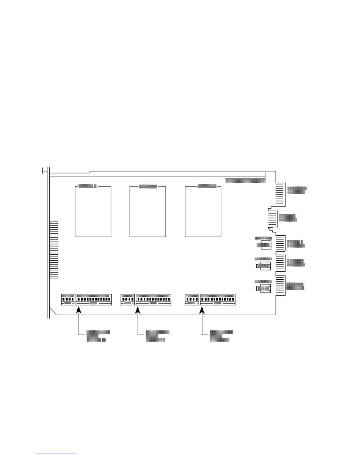
PN 88300150
7.1 Introduction
There are 3 sets of DIP-Switches and 3 two-position jumpers on the MT2834MR card. To remove the
MT2834MR modem card from the CC4800 rack, pull the ejector levers away from the rack (if necessary
loosen the retaining screw first), then carefully slide the modem card out of the rack.
The DIP-Switches are used to enable or disable various user-selectable options. Each DIP-Switch is set
to a factory default setting that is useful in most applications. Each set of DIP-Switches is labeled with a
number and can be set to either the UP (marked “OPEN”) or Down pos ition. The ind i vid ua l swit ch es can
easily be set with your fingerna il or a penci l tip.
Note: Before changing any DIP-Switches on the MT2834MR, please consult your MultiCommManager
software manual. Many of these options can be controlled by the software.
Each of the 3-pin (two-position) jumpers is used to select options. They are also pre-set to factory default
settings that should be effecti ve for your app li ca tio n. The defau lt set ting can be easily changed to an
option setting by removing the shorting plug and replacing in the option position.
The following sections detail the function of each DIP-Switch and jumper located on the MT2834MR PC
board.
4/3/01 65
Figure 7-1. Location of PC Board Controls
Page 66
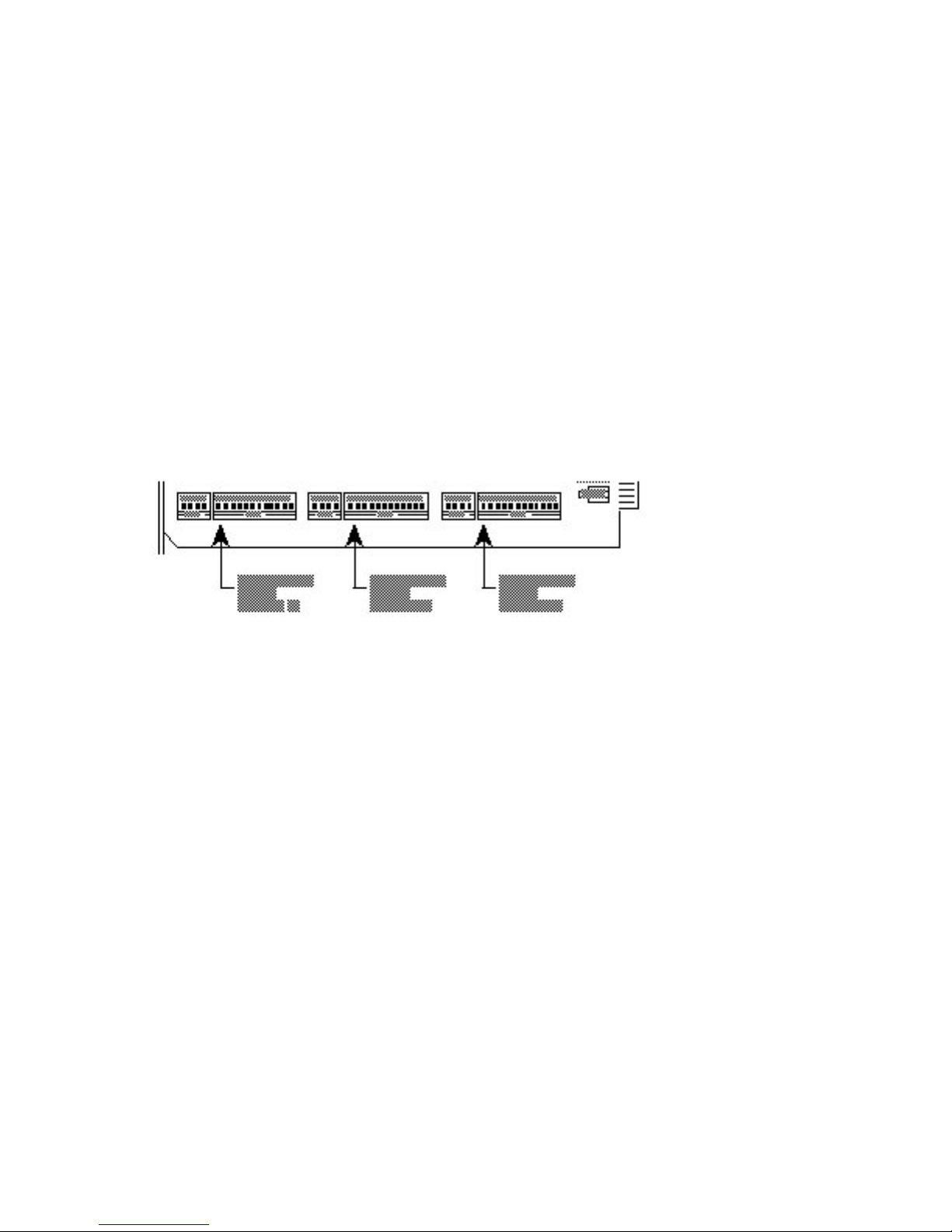
PN 88300150
7.2 16-Position DIP-Switches
The MT2834MR PC board contains three pairs of DIP-Switch blocks. Each pair of DIP-Switch blocks is
numbered 1-12 and 13-16, and each pair of DIP-Switch blocks is related to each of the three on-board
modems, as shown below.
Figure 7-2. DIP-Switches
7.3 16-Position DIP-Switch Settings
Each individual switch, numbered 1-12 and 13-16, and can be set to either the Up (marked “OPEN”) or
Down position. Each of these DIP-Switches controls the following functions for its corresponding on-board
modem.
7.3.1 DIP-Switches #1 - #12
Switch #1
Forced DTR - “DTR”
(Asynchronous/Synchronous Mode/Leased Line/Dial-Up)
The MT2834MR must have a high DTR signal in order to operate. This signal is provided to each modem
by the terminal or computer to which it is attached, through the RS232/V.24 interface on pin 20. If your
terminal is not providing DTR to the modem, you can force the DTR signal DIP-Switch #1.
DTR function normally = Switch #1 UP
DTR forced ON = Switch #1 DOWN
(Factory Default Setting = UP)
4/3/01 66
Page 67

PN 88300150
Switch #2
Flow Control - &E4/&E5
(Asynchronous Mode/Leased Line/Dial-Up)
With Hardware Flow control, the modem uses its RS232C/V.24 interface to control the flow of data from
the computer or terminal to which it is atta ch ed. CTS sig n al on Pi n 5 of the RS232C/V.24 is brought low
to stop the flow of data, and is brought high to restart it. Place DIP-Switch #2 in the UP position to enable
Hardware Flow control (&E4). Xon/Xoff Flow control (&E5) is another method of flow control in which
Xon/Xoff characters in the data dictates the start and stop of data flow from the computer or terminal.
Place DIP-Switch #2 in the DOWN position to enable Xon/Xoff Flow control.
Hardware Flow Control (&E4) = Switch #2 UP
Xon/Xoff Flow control (&E5) = Switch #2 DOWN
(Factory Default Setting = UP)
Switch #2
SDLC/BSC Selection
(Synchronous Mode/Leased Line/Dial-Up)
Synchronous Data Link Control (SDLC) and Binary Synchronous Control (BSC) are two error correction
protocols used in the IBM Mainfra me en vir o nme nt. Pl ace DIP- Sw it ch #2 in t he UP pos it ion to se le ct SDLC
mode. Place DIP-Switch #2 in the DOWN position for BSC mode.
SDLC Mode = Switch #2 UP
BSC Mode = Switch #2 DOWN
(Factory Default Setting = UP)
Switch #3
Enable/Suppress Responses - “Q”
(Asynchronous Mode/Dial-Up)
In some applications in Asyn chronous mode, you may want to sup pres s al l responses from the modem.
Place DIP-Switch #3 in the DOWN position to enable result code responses (Q0). Place DIP-Switch #3 in
the UP position for answer mode without responses and echo off, (but with originate still intelligent)(Q2).
Enable Responses: Originate/Answer (Q0)
= Switch#3 DOWN
Suppress Responses: Answer (Q2)
= Switch #3 UP
(Factory Default Setting = DOWN)
Switch #3
dB Transmission Levels
(Asynchronous/Synchronous Mode/Leased Line)
The MT2834MR can adjust to dB transmission levels required by some phone carriers. With DIP-Switch
#3 in the DOWN position, the MT2834MR transmits at 0 db. With DIP-Switch #3 in the UP position,
transmission is at -15dB.
0dB Transmission = Switch #3 DOWN
-15dB Transmission = Switch #3 UP
(Factory Default Setting = UP)
Note: dB transmission levels on International models may be different from those values shown above.
Note: Switch #3 has no effect in leased line mode in the MT2834MRK.
4/3/01 67
Page 68

PN 88300150
Switch #4
AS/400 Mode
(Synchronous Mode/Leased Line/Dial-Up)
The MT2834MR can function in an IBM AS/400 environment. Place DIP-Switch #4 in the DOWN position
to cause the MT2834MR to operate via IBM command set.
Place DIP-Switch #4 in t he UP position to disable AS/400 mode
Note: The MT2834MR must be in Command mode to allow AS/400 mode operation).
AS/400 Mode Enabled = Switch #4 DOWN
AS/400 Mode Disabled = Switch #4 UP
(Factory Default Setting = UP)
Switch #4
UNIX UUCP Spoofing
(Asynchronous Mode/Leased Line/Dial-Up)
The MT2834MR can be used with UNIX equipment which employs ACK flow control to monitor data
integrity. The MT2834MR can do UUCP “spoofing”, where the modem is able to generate ACKs at the
DTE interface. Data is then transmitted more time-efficiently, because the delay of waiting for data to be
received then for the ACK to be returned at the remote end is eliminated. Place DIP-Switch #4 in the
DOWN position to enable UUCP spoofing.
UUCP Spoofing Enabled = Switch #4 DOWN
UUCP Spoofing Disabled = Switch #4 UP
(Factory Default Setting = UP)
Switch #5
Disable Auto-Answer - “Ans”
(Asynchronous Mode/Synchronous Mode/Dial-Up)
In some originate-only applications, you may wish to disable the MT2834MR’s automatic answering
capabilities. This may be true if you have a telephone set attached to a modem and wish to receive voice
calls that you yourself would answer instead of the modem.
Auto-Answer Enabled = Switch #5 UP
Auto-Answer Disabled = Switch #5 DOWN
(Factory Default Setting = UP)
Switch #5
Originate/Answer Mode
(Asynchronous/Synchronous Mode/Leased Line)
The MT2834MR can function in either Originate mode or Answer mode. To enable Answer mode, place
DIP-Switch #5 in the UP position. To enable Originate mode, place DIP-Switch #5 in the DOWN position.
Origination Enabled = Switch #5 DOWN
Answer Enabled = Switch #5 UP
(Factory Default Setting = UP)
4/3/01 68
Page 69

PN 88300150
Switch #6
Maximum Throughput Setting
(Asynchronous Mode/Leased Line/Dial-Up)
In some applications, you may want to dial into services with maximum throughput on. Other applications
require maximum throughput off (e.g., service not supporting error correction, or the V.42 handshake
interferes with logon sequence). Switch #6 controls three important parameters, which in effect enable or
disable maximum through put (err or corr e cti on, sp eed con ver sio n and ser i al por t spe ed).
Maximum Throughput Enabled = Switch #6 UP
Maximum Throughput Disabled = Switch #6 DOWN
(Factory Default Setting = UP)
Switch #6
Slave Clocking
(Synchronous Mode/Leased Line/Dial-Up)
In Synchronous mode, DIP-Switch #6 controls the timing at the receive clock. The originating side, in
effect, adjusts to the timing at the remote (“slave”) side.
Slave Clocking Enabled = Switch #6 DOWN
Slave Clocking Disabled = Switch #6 UP
(Factory Default Setting = UP)
Switch #7
Request To Send Forced - “RTS”
(Asynchronous/Synchronous Mode/Leased Line/Dial-Up)
If your computer or terminal uses RTS-CTS protocol (normally used in synchronous applications, but also
if you are using hardware pacing for V.42 error correction or speed conversion), you may want to switch
RTS to function independent of CTS (DIP-Switch #7 UP). For most applications, especially asynchronous,
Switch #7 should be set so that RTS is forced on (DIP-Switch #7 DOWN).
RTS functions Normally = Switch #7 UP
RTS forced ON = Switch #7 DOWN
(Factory Default Setting = DOWN)
Switch #8
Enable/Disable Command Mode - “Com”
(Asynchronous/Synchronous Mode/Leased/Dial-Up)
In some applications you may want to disable Command mode so that the modem will not recognize or
react to AT or any other commands. This may be true in strictly auto-answer applications where no call
origination will be required. DIP-Switch #8 enables or disables the modem’s ability to recogni ze
Command mode characters. The factory default setting is Command mode enabled.
Disable Command Mode = Switch #8 UP
Enable Command Mode = Switch #8 DOWN
(Factory Default Setting = DOWN)
Switch #9
No function.
4/3/01 69
Page 70

PN 88300150
Switch #10
Leased Line/Dial-Up Operation - “DDD”
(Asynchronous/Synchronous Mode/Leased Line/Dial-Up)
The MT2834MR can operate in both leased-line or dial-up modes. This switch controls leased-line/dial-up
operation. For dial-up operation, place DIP-Switch #10 in the UP position. For leased-line operation, place
DIP-Switch #10 in the DOWN position.
Dial-Up Operation = Switch #10 UP
Leased Line Operation = Switch #10 DOWN
(Factory Default Setting = UP)
Switch #11
“AT” Responses/Multi-Tech Responses
(Asynchronous Mode/Leased Line/Dial-Up)
In Asynchronous mode (DIP-Switch #12 DOWN), the MT2834MR responds with result codes according to
the Multi-Tech command response set or with the “AT” command response set (DIP-Switch #11 in the UP
position). The &Q command performs the same function of choosing AT or Multi-Tech responses and is
explained further in Chapter 5.
“AT” Responses (&Q1) = Switch #11 UP
Multi-Tech Responses (&Q0) = Switch #11 DOWN
(Factory Default Setting = DOWN)
For more information on Result Codes, refer to Chapter 3.
Switch #11
Internal/External Clocking
(Synchronous Mode/Leased Line/Dial-Up)
With the MT2834MR in Synchronous Mode, the transmit clock can be supplied by the DTE on pin 24 of
the RS232C/V.24 interface by DIP-Switch #11 positioned UP. DIP-Switch #11 in the DOWN position
enables the DCE to control clocking.
External Clock (pin 24) = Switch #11 UP
Internal Clock (pins 15/17) = Switch #11 DOWN
(Factory Default Setting = DOWN)
Switch #12
Asynchronous/Synchronous Operation - “Sync”
(Asynchronous/Synchronous Mode/Leased Line/Dial-Up)
The MT2834MR can operate in both asynchronous mode and synchronous mode. When in synchronous
mode, start and stop bits are eliminated. The modem’s internal clock circuits on the RS232C/V.24 pins 15
and 17, are activated. The MT2834MR’s Com man d Mod e wi ll not be accessible in the synchro nou s
mode. For synchronous operation, you may want to set the RTS forcing and CTS forcing DIP-Switches so
that both of signals act normally (not forced on).
Synchronous Operation = Switch #12 UP
Asynchronous Operation = Switch #12 DOWN
(Factory Default Setting = DOWN)
4/3/01 70
Page 71

PN 88300150
7.3.2 DIP-Switches #13 - #16
Switches #13 and #14 - Speed Selection
DIP-Switches #13 and #14 are used for speed selection (mainly in call origination leased line
applications).
DIP-Switch
28800 bps Operation #13 #14
UP UP
19200 bps Operation #13 #14
DOWN UP
14400 bps Operation #13 #14
UP DOWN
9600 bps Operation #13 #14
DOWN DOWN
NOTE: The modem baud rate command, $MB, overrides the setting of DIP-Switches #13 - #14.
Switch #15
Carrier Detect/DSR Source - “DSR”
(Asynchronous/Synchronous Mode/Dial-Up/Leased Line)
Some terminals react in unusual ways to the toggling of the Carrier Detect (CD - RS232C/V.24 pin 6)
signals. The most common symptom is that the modem will not respond to commands, or will not echo
characters. In these cases, force these two signals On in order for the terminal to communicate properly
with the modem when the modem is in Command mode by placin g DIP- Sw it ch #15 in the DO WN
position. With Switch #15 UP, the state of the CD and DSR signals depend on the On-Line status.
CD and DSR normal = Switch #15 UP
CD and DSR forced On = Switch #15 DOWN
(Factory Default Setting = UP)
Switch #16
2-Wire/4-Wire Leased Line
(Asynchronous/Synchronous Mode/Leased Line)
2-Wire Leased Line = Switch #16 UP
4-Wire Leased Line = Switch #16 DOWN
(Factory Default Setting = DOWN)
7.4 Jumper Settings
The MT2834MR has three two-position jumpers (one for each modem) for OOS and service. Each set of
OOS jumpers defines pin 25 of the RS232C/D interface as an input (OOS) or an output (Test Mode) for
one of the three modems. Each is set to a default of OOS (U.S.); international models have a default
setting of Test Mode.
There is also a factory-set selection for MI/MIC (modified dial-up phone line interface that allows dialing
by an external device such as an 801 Dialer, computer or PBX/CBX system dialer).
7.4.1 ATEST/AV54 Jumper (S105)
Jumper S105 sets pin 25 of Modem A as input (OOS) for the default and output (Test Mode) as the option
setting on domestic (US) modems. On international modems, Jumper S105 sets pin 25 of Modem A as
input (OOS) for the option, and output (Test Mode) as the default setting. The location of these jumpers
can be seen in Figure 7-1 on the right-hand side of the board.
4/3/01 71
Page 72

PN 88300150
For Modem A:
ATEST/AV54 ATEST/AV54
Pin 25 Output (OOS) Pin 25 Input (Test Mode)
(MT2834MR Default) (MT2834MRI Default)
7.4.2 BTEST/BV54 Jumper (S205)
Jumper S205 sets pin 25 of Modem B as input (OOS) for the default and output (Test Mode) as the option
setting on domestic (US) modems. On international modems, Jumper S205 sets pin 25 of Modem B as
input (OOS) for the option, and output (Test Mode) as the default setting.The location of these jumpers
can be seen in Figure 7-1 on the right-hand side of the board.
For Modem B:
BTEST/BV54 BTEST/BV54
Pin 25 Output (OOS) Pin 25 Input (Test Mode)
(MT2834MR Default) (MT2834MRI Default)
7.4.3 CTEST/CV54 Jumper (S305)
Jumper S305 sets pin 25 of Modem C as input (OOS) for the default and output (Test Mode) as the
option setting on domestic (US) modems. On international modems, Jumper S305 sets pin 25 of Modem
C as input (OOS) for the option, and output (Test Mode) as the default setting. The location of these
jumpers can be seen in Figure 7-1 on the right-hand side of the board.
For Modem C:
CTEST/CV54 CTEST/CV54
Pin 25 Output (OOS) Pin 25 Input (Test Mode)
(MT2834MR Default) (MT2834MRI Default)
4/3/01 72
Page 73

PN 88300150
8.1 Introduction
This chapter starts out with statements about your modem’s 2-year warranty. The next section, Tech
Support, should be read carefu ll y if you have qu est io ns or problems with your modem. It include s the
technical support telephone numbers, space for recording your modem information, and an explanation of
how to send in your modem should you require service. The final sections explains ourweb presence.
8.2 Limited Warranty
Multi-Tech Systems, Inc. (“MTS”) warrants that its products will be free from defects in material or
workmanship for a period of two years from the date of purchase, or if proof of purchase is not provided,
two years from date of shipment.
MTS MAKES NO OTHER WARRANTY, EXPRESSED OR IMPLIED, AND ALL IMPLIED WARRANTIES
OF MERCHANTABILITY AND FITNESS FOR A PARTICULAR PURPOSE ARE HEREBY
DISCLAIMED.
This warranty does not apply to any products which have been damaged by lightning storms, water, or
power surges or which have been neglected, altered, abused, used for a purpose other than the one for
which they were manufactured, repaired by the customer or any party without MTS’s written authorization,
or used in any manner inconsistent with MTS’s instru ctio ns.
MTS’s entire obligation under this warranty shall be limited (at MTS’s option) to repair or replacement of
any products which prove to be defective within the warranty period, or, at MTS’s option, issuance of a
refund of the purchase price. Defective products must be returned by Customer to MTS’s factory
transportation prepaid.
MTS WILL NOT BE LIABLE FOR CONSEQUENTIAL DAMAGES AND UNDER NO CIRCUMSTANCES
WILL ITS LIABILITY EXCEED THE PURCHASE PRICE FOR DEFECTIVE PRODUCTS.
8.3 Tech Support
Multi-Tech has an excellent staff of technical support personnel available to help you get the most out of
your Multi-Tech product. If you have any questions about the operation of this unit, call (800) 972-2439
(U.S.A. or Canada) or (763) 785-3500 (Local or International). Please fill out the modem information
(below), and have it available when you call. If your modem requires service, the tech support specialist
will tell you how to send in your modem (see Section 8.4).
8.3.1 Recording Modem Information
Please fill in the following information on your Multi-Tech modem. This will help tech support in answering
your questions. (The same inform ati on is reques ted on the War ran ty Registration Card.)
Modem Model No.:_______________________________
Modem Serial No.: _______________________________
Modem Firmware Version:_________________________
FAX Software Version:____________________________
DataComm Software Version: ______________________
The modem model and serial numbers are silkscreened on the bottom of your modem. The software
versions are printed on the diskette labels. Type ATI1 to display the modem firmware version.
Please note the status of your modem before calling tech support. This status can include LED indicators,
screen messages, diagnostic test results, problems with a specific application, etc. Use the space below
to note modem status (before calling for service or tech support):
____________________________________________________
____________________________________________________
4/3/01 73
Page 74

PN 88300150
8.4 Service
In the event that repair service is required, you may send your modem to our Mounds View factory in the
USA. Products requiring repair and are shipped to us from outside the USA must have a Returned
Materials Authorization (RMA) and shipping instructions. To return products for repair from inside the
USA, no RMA is required, simply send products to us freight prepaid. Include a description of the
problem, a return shipping address, and a check or purchase order for out-of-warranty repairs.
Please send products which require repairs to the following address:
Multi-Tech Systems, Inc.
2205 Woodale Drive
Mounds View, MN 55112
Attn: Repair
If you are shipping products from outside the USA, please contact our Repair Department prior to your
shipment for an RMA. You may contact us by telephone or fax at the following numbers:
Telephone: +(763) 785-3500
Fax: +(763) 785-9874
8.7 How to Find Multi-Tech on the Internet
Multi-Tech is on the Internet at http://www.multitech.com .
8.9 Upgrading the MT2834MR Firmware
The MT2834MR has a Flash PROM which contains firmware code for the hardware. At various times,
Multi-Tech may add enhancements and/or fixes to the firmware. The flash technology used in the
MT2834MR allows these upgrades to be loaded directly into the PROM chip through the modem’s serial
port.
8.9.1 Using FlashPro to Upgrade Modem Firmware
1. Download FLASHPRO.ZIP and a new .HEX file from the Multi-Tech web site.
2. Unzip the FLASHPRO.ZIP file. Place this unzipped file and the .HEX file in the same directory.
3. Run FlashPro by typing FLASHPRO and pressing ENTER at the DOS prompt.
4. Highlight ’Configure’ option in the MAIN MENU and press ENTER. Highlight ’Active Port’ and select
the COM port to which you have your MT2834MR attached. Highlight ’Baud Rate’ and select the rate
you want to program at. Press ESC when finished.
5. Highlight ’Select File to Program’ option in the MAIN MENU. Highlight the .HEX file. Hit ESC when
finished.
6. Highlight ’Program Firmware’ option in the MAIN MENU. You are prompted to confirm the file to
program.
6. Return to step 3, if you have not successfully programmed FlashPro. Or call Multi-Tech’s Technical
Support (see sections 8.3).
4/3/01 74
Page 75

PN 88300150
Appendix A
ASCII/Hex/Decimal Conversion Chart
CTRLCODE HEX DEC CODE HEX DEC CODE HEX DEC CODE HEX DEC
@ NUL 00 0 SP 20 32 @ 40 64 60 96
A SOH 01 1 ! 21 33 A 41 65 a 61 97
BSTX 02 2 “ 22 34 B 42 66 b 62 98
C ETX 03 3 # 23 35 C 43 67 c 63 99
D EOT 04 4 $ 24 36 D 44 68 d 64 100
E ENQ 05 5 % 25 37 E 45 69 e 65 101
F ACK 06 6 & 26 38 F 46 70 f 66 102
G BEL 07 7 ‘ 27 39 G 47 71 g 67 103
H BS 08 8 ( 28 40 H 48 72 h 68 104
I HT 09 9 ) 29 41 I 49 73 i 69 105
J LF 0A 10 * 2A 42 J 4A 74 j 6A 106
K VT 0B 11 + 2B 43 K 4B 75 k 6B 107
L FF 0C 12 , 2C 44 L 4C 76 l 6C 108
M CR 0D 13 - 2D 45 M 4D 77 m 6D 109
N SO 0E 14 . 2E 46 N 4E 78 n 6E 110
O SI 0F 15 / 2F 47 O 4F 79 o 6F 111
P DLE 10 16 0 30 48 P 50 80 p 70 112
Q DC1 11 17 1 31 49 Q 51 81 q 71 113
R DC2 12 18 2 32 50 R 52 82 r 72 114
S DC3 13 19 3 33 51 S 53 83 s 73 115
T DC4 14 20 4 34 52 T 54 84 t 74 116
U NAK 15 21 5 35 53 U 55 85 u 75 117
V SYN 16 22 6 36 54 V 56 86 v 76 118
W ETB 17 23 7 37 55 W 57 87 w 77 119
X CAN 18 24 8 38 56 X 58 88 x 78 120
Y EM 19 25 9 39 57 Y 59 89 y 79 121
Z SUB 1A 26 : 3A 58 Z 5A 90 z 7A 122
[ ESC 1B 27 ; 3B 59 [ 5B 91 { 7B 123
\ FS 1C 28 < 3C 60 \ 5C 92 | 7C 124
] GS 1D 29 = 3D 61 ] 5D 93 } 7D 125
RS 1E 30 > 3E 62 ^ 5E 94 – 7E 126
— US 1F 31 ? 3F 63 _ 5F 95 DEL 7F 127
NUL Null, or all zeros DC1 Device Control 1 SI Shift In
SOH Start of Heading DC2 Device Control 2 SO Shift Out
STX Start of Text DC3 Device Control 3 SYN Sync.
ETX End of Text DC4 Device Control 4 LF Line Feed
EOT End of Transmission CAN Cancel FF Form Feed
ACK Acknowledge EM End of Medium ENQ Enquiry
BEL Bell or Alarm SUB Substitute ESC Escape
BS Backspace FS File Separator DLE Data Link Escape
HT Horizontal Tab GS Group Separator NAK Negative Acknowledge
VT Vertical Tab RS Record Separator CR Carriage Return
ETB End Transmission Block DEL Delete
4/3/01 75
Page 76

PN 88300150
Appendix B
Dial Pulse and Tone-Dial Frequencies
DIAL PULSES
B
Closed
A
Open
Digit 2 Digit 1
In the example above, the digit 2 is pulse dialed, followed by the digit 1. Each pulse consists of an A
mSec. open and a B mSec. closed, where A will be either 60 or 67 mSec and B will be either 40 or 33
mSec., for a total of 100 mSec. per pulse, or a rate of 10 pulses per second. The interdigital pause time is
800 mSec. The pulse ratios are contr ol led by the &P command*.
TONE DIAL FREQUENCIES
Hz Digits
697
770
852
941
Hz 1209 1336 1477
The tone-dialing method combines two frequencies for each of the twelve digits found on a Touch Tone
dial pad. This method is referred to as Dual-Tone Multi-Frequency (DTMF) dialing.
The four horizontal rows on a Touch-Tone keypad use the four low frequencies (697, 770, 852, 941 Hz),
while the three vertical columns use the three high frequencies (1209, 1336, 1477 Hz). The generally
accepted tone frequency tolerance is +0.02%.
*Not applicable in BABT models
For example, the digit 4 would be dialed by combining two tone frequencies. It would use the frequency
770 Hz from the second row, and the frequency 1209 Hz from the first column. In another example, the
digit 9 would be dialed with the tone frequencies of 852 Hz and 1477 Hz.
The extended DTMF characters (A, B, C, D) are the high-end frequencies (1633 Hz) defined on some
telephone sets with a fourth vertical column of buttons. This fourth column provides for extended PBX
control functions; the actual functions provided are dependent on the PBX manaufacturer’s
implementation and feature set.
Hz Digits
697 1 2 3 A
770 4 5 6 B
852 7 8 9 C
941
Hz 1209 1336 1477 1633
* 0 # D
4/3/01 76
Page 77

PN 88300150
DIP-Switch Summary
DIP-Switch Condition Effect
Asynchronous Mode
Appendix C
#1 *UP DTR dependent on interface
#2 *UP Hardware Flow Control
#3 UP Disable Command Mode Response (dial up)
#3 UP -10 dB Transmission (leased line)
Note: dB transmission levels on International models may be different from those values shown above.
Note: Switch #3 has no effect in leased line mode in the MT2834MRK.
#4 *UP UUCP Spoofing Disabled
#5 *UP Enable Automatic Answer (dial up)
#5 *UP Answer Mode (leased line)
#6 *UP Max throughput Enabled
#7 UP RTS dependent on Interface
#8 UP Disable Command Mode
#9 UP No function
#10 *UP Dial-Up Operation
#11 UP "AT" Responses
#12 UP Sy nchronous Mode
See page C-3 for information on DIP-Switches #13 - #16
Down DTR force On at all times
Down Xon/Xoff Flow Control
*Down Enabl e Command M ode Response (dial up)
*Down 0 dB Transmiss i on (l eased line)
Down UUCP Spoofing E nabl ed
Down Disable Automatic Answer (dial up)
Down Originate Mode (leased line)
Down Max throughput Dis abl ed
*Down RTS forced On at all times
*Down Enabl e Command M ode
*Down
Down Leased Line Operation
*Down Multi-Tech Responses
*Down Asynchronous Mode
4/3/01 77
Page 78

PN 88300150
DIP-Switch Condition Effect
Synchronous Mode
#1 *UP DTR Dependent On interface
#2 *UP SDLC Mode On
#3 UP Disable Command Mode Response (dial up)
#3 UP -15 dB Transmission (leased line)
Note: dB transmission levels on International models may be different from those values shown above.
Note: Switch #3 has no effect in leased line mode in the MT2834MRK.
#4 *UP AS/400 Mode Disabled
#5 *UP Enable Automatic Answer (dial up)
#5 *UP Answer Mode (leased line)
#6 *UP Slave Clocking Disabled
#7 UP RTS Dependent on interface
#8 UP Disable Command Mode
#9 UP No function
#10 *UP Dial-Up Operation
#11 UP External Clock
#12 UP Sy nchronous Mode
Down DTR forced On at all times
Down BSC Mode On
*Down Enabl e Command M ode Response (dial up)
*Down 0 dB Transmiss i on (l eased line)
Down AS/400 Enabled
Down Disable Automatic Answer (dial up)
Down Originate Mode (leased line)
Down Slave Clocki ng Enabl ed
*Down RTS Forced On at all times
*Down Enabl e Command M ode
*Down
Down Leased Line Operation
*Down Internal Clock
*Down Asynchronous Mode
DIP-Switches #13 - #16
Synchronous and Asynchronous Mode
#13/#14 UP/UP* 28.8 K bps Operation
#13/#14 DOWN/UP 19.2 K bps Operation
#13/#14 UP/DOWN 14.4 Kbps Operation
#13/#14 DOWN/DOWN 9600 bps Operation
#15 UP* CD/DSR Norm al
#16 UP 2-wire l eased-line
DOWN CD/DSR Forced On
DOWN* 4-wire leased-line
Note: The modem baud rate command, $MB, overrides the setting of DIP-Switches #13 and #14.
Note: Switches #13 and #14 are used for speed selection in leased line and call origination applications.
*Factory Default Setting
4/3/01 78
Page 79

PN 88300150
Appendix D
Result Code Summary
DIGIT WORDS EFFECT
“Multi-Tech” Result Codes*
0 OK Command was executed without error; ready for next command.
1 CONNECT Modem has detected carrier and gone on-line.
2 RING Modem has detected ring caused by incoming call.
3 NO CARRIER No carrier signal has been detected within allowed time.
4 ERROR Error in Command line (too many, or invalid characters).
5 CONNECT 1200 Modem has detected carrier at 1200 bps and gone on-line.
6 NO DIAL TONE No dial tone has been dete cted.
7 BUSY A busy signal has been detected.
8 NO ANSWER Remote system did not an swer.
9 CONNECT 2400 Modem has detected carrier at 2400 bps and gone on-line.
11 CONNECT 4800 Modem has detected carrier at 4800 bps and gone on-line.
12 CONNECT 9600 Modem has detected carrier at 9600 bps and gone on-line.
13 CONNECT 14400 Modem has detected carrier at 14400 bps and gone on-line.
19 CONNECT 19200 Modem has detected carrier at 19200 bps and gone on-line.
21 CONNECT 21600 Modem has detected carrier at 21600 bps and gone on-line.
23 CONNECT 1275 Modem is connected in V.23 mode.
24 CONNECT 24000 Modem has detected carrier at 24000 bps and gone on-line.
26 CONNECT 26400 Modem has detected carrier at 26400 bps and gone on-line.
28 CONNECT 28800 Modem has detected carrier at 28800 bps and gone on-line.
Note: If the MT2834MR is used in MNP Reliable mode, the following Result Codes
change:
1R CONNECT RELIABLE
5R CONNECT 1200 RELIABLE
9R CONNECT 2400 RELIABLE
11R CONNECT 480 0 RELI AB LE
12R CONNECT 960 0 RELI AB LE
13R CONNECT 14400 R ELIA BL E
19R CONNECT 19200 R ELIA BL E
21R CONNECT 21600 R ELIA BL E
24R CONNECT 24000 R ELIA BL E
26R CONNECT 26400 R ELIA BL E
28R CONNECT 28800 R ELIA BL E
*See Note 2 for “AT Command Set Result Codes”.
4/3/01 79
Page 80

PN 88300150
Note: If the MT2834MR used in LAP-M Reliable mode, the following Result Codes change:
1L CONNECT LAPM
5L CONNECT 1200 LAPM
9L CONNECT 2400 LAPM
10L CONNECT 4800 LAPM
12L CONNECT 9600 LAPM
13L CONNECT 14400 LA PM
19L CONNECT 19200 LAPM
21L CONNECT 21600 LA PM
24L CONNECT 24000 LA PM
26L CONNECT 26400 LA PM
28L CONNECT 28800 LA PM
Note 1: If the MT2834MR is used with data compression, the word COMPRESSED or the letter C is
added to the result codes.
Note 2: If Standard AT Command Set 2400 Result Codes are selected with &Q command, the following
Result Codes change:
9 (not used)
10 CONNECT 2400 Modem has detected carrier at 2400 bps and gone on-line.
4/3/01 80
Page 81

PN 88300150
Appendix E
S-Register Summary
* indicates Values for MT2834MRK units only.
REGISTER UNIT RANGE DEFAULT DESCRIPTION
S0 1 ring 0-255 1 Sets number of rings until modem answers.
S1 1 ring 0-255 0 Counts rings which have occurred.
S2 ASCII 0-127 43 Sets Escape Code chara cter (def au lt is pl us + s ign).
S3 ASCII 0-127 13 Sets character recognized as RETURN (default is CTRL-M).
S4 ASCII 0-127 10 Sets character recognized as LINE FEED (default is CTRL-J).
S5 ASCII 0-32 8 Sets character recognized as 127 BACKSPACE (default is
CTRL-H).
S6 1 second 2-255 2 Defines wait-time for dial tone. 4-7* 4*
S7 1 second 1-255 45 Defines how long modem will wait for carrier before aborting call.
1-45*
S8 1 second 0-255 2 Sets pause time caused by a comma character in a dial
command. 4-7*4*
S9 100 mSec 1-255 6 Sets Carrier Detect response time.
S10 100 mSec 1-255 7 Sets delay time between when carrier is lost and when modem
disconnects.
S11 1 mSec 1-255 70 Sets time duration of and spacing between tones in tone-dialing
80-255* 80*
.
S13 ASCII 0-127 37 Defines Remote Configuration Escape Character
S17 10 mSec 0-2500 250 mSec Defines length of break time seconds (space) to PC.
S18 30 min. 10-255 30 Modem monitors leased line to see if it’s operational and will try
to restore leased line connection.
S19 1 min 0-255 1 Dial-backup timer used for timing dial-line back-up.
S24 50 mSec 0-255 20 Sets DSR/CTS/CD dropout time. The default (20) equals one
second.
S25 100 mSec 0-255 0 Sets DTR dropout time. The default (0) default equals 50 mSec.
S30 min 0-255 0 Inactivity timer used to disconnect modem.
S32 1 second 0-255 2 mSec S32 sets the time that the modem waits for <CR> to be entered
during Escape Sequen ce exe cut ion.
S34 ASCII 0-60 10 Sets the number of command characters allowed for Escape
Sequence entry.
S36 1 sec 0-255 0 When DTR is low for S36 seconds, the modem sets OOS.
S37 1 sec 5-255 5 When DTR is high for S37 seconds, the modem clears OOS.
S48 n/a ** 0 Defines the speed at which the modem connects within V.34
mode (**range: 28,26,24,21,19,16,14,12, 96,and 48).
4/3/01 81
Page 82

PN 88300150
Appendix F
Command Summary
COMMAND VALUES DESCRIPTION
AT Attention Code that precedes most command strings except A/, A: and Escape Codes.
RETURN Pressing RETURN key executes most commands.
A Answer call, even if no ring present.
A/ Repeat last command. Do not precede this command with AT. Do not hit ENTER to
&A Answerback (proprietary feature)
A:** Continuous redial (10 redials in DOC units) of
$An n = 0 or 1 *** $A0 discards data during auto-reliable time period.
#An n = 0 thru 3 *** #A0 selects initial handshake at 28,800 to 24,000 to 21,600 to 19,200 to 16,800 to
#A2 selects initail handshake at 28,800 to 24,000 to 21,600 to 19,200 to 14,400 to
%ASn n = 0 or 1 *** %AS0 disables IBM AS/400 Support
Bn** n = 0 or 1 B0 selects ITU-T answer tone at 300 baud.
&Bn n = 0 or 1 *** &B0 means normal transmit buffer size.
&BSn n = 0 or 1 &BS0 means maximum transmit bl ock size of
$BAn n = 0 or 1 *** $BA0 means Baud Adjust is off, speed
&Cn n = 0, 1, &C0 forces Carrier Detect on.
2, or 4 *** &C1 lets Carrier Detect act normally.
*Cn n=0 thru 2 *** *C0 turns off Caller ID detection.
&CDn n = 0 or 1 *** &CD0 enables a cleardown on disconnect.
execute.
last number until answered.
$A1 buffers data during auto-reliable time period.
14,400 to 12,000 to 9600 to 4800 to 2400 to 1200 to 300 bps.
#A1 selects initail handshake at 28,800 bps only.
9600 to 4800 bps only.
#A3 selects initial handshake at 2400 to 1200 to 300 bps only.
%AS1 enables IBM AS/400 Support
*** B1 selects Bell answer tone at 300 baud.
&B1 means reduced transmit buffer size.
64 characters.
*** &BS1 means maximum transmit block size of
256 characters.
conversion is on.
$BA1 means Baud Adjust is on, speed
conversion is off.
&C2 lets Carrier Detect drop S24 time on
disconnect.
&C4 resets modem when Carrier Detect drops.
*C1 turns on Caller ID detection for the MMM.
*C2 is storable in MT2834MR memory and turns on Caller ID reporting on the serial port by
the MMM.
*C3 lets you view the last Caller ID’s number.
&CD1 disables a cleardown on disconnect.
Ds s = phone # Dial a telephone number “s,” where s may include up to 60 digits or T, P, R, comma
DsDn s = phone # Store telephone number. To store, phone
d = 0 thru 9 number "s" is entered and followed by N and then Directory Number "d".
&Dn n = 0 thru 3 &D0 DTR is ignored.
*** &D2 lets modem react to DTR normally.
$Dn n = 0 or 1 *** $D0 disables DTR Dialing.
En n = 0 or 1 E0 means do not echo Command Mode Character.
*** E1 means do echo Command Mode characters.
4/3/01 82
and ; characters.
&D1 means modem returns to command
mode.
&D3 causes modem to reset to modem default parameters.
$D1 enables DTR Dialing.
Page 83

PN 88300150
$En n = 0 or 1 *** $E0 disables 300 baud error correction.
&En n = 0 thru 15 &E0 means V.42 Normal Mode.
$EBn n = 0 or 1 *** $EB0 enables 10 bit mode.
%En n=0 thru 5 % E0 = Modem Won’t Escape.
*** % E1 = +++ Method (default setting).
#Fn n = 0, 1, 8, #F0 means no fallback when on-line.
or 9 #F1 means fallback from 28800 to 2400 bps
&F &F loads factory default values from ROM.
$Fn n = 0 or 1 $F0 means do not fall back to normal connect if CR received.
&Gn** n = 0, 1 or 2 *** &G0 turns off ITU-T guard tones.
Hn n = 0 or 1 H0 means Hang Up (go on hook).
$Hn n = 1 thru 3 $H1 brings up Help Screen #1.
*Hn n = 0 or 1 *** *H0 means modems busy out after disconnect disabled.
In n = 0 or 1 I0 requests modem ID #.
L Lists all stored telephone numbers in memory.
L5 L5 lists all current operating parameters.
L6 L6 lists all current S-Register values.
L7 L7 lists additional parameters.
L8 L8 lists on-line diagnostics
#Ln n = 0 thru 3 *** #L0 means modems negotiate V.42 Mode.
&Ln n = 0,1,2A, &L0 selects Dial-up line operation
2D,4A,4D &L1 all ows a single attempt at laes ed line connecti on
$E1 enables 300 baud error correction.
*** &E1 means V.42 Auto-reliable Mode.
&E2 means V.42 Reliable Mode.
&E3 means no modem-initiated flow control.
*** &E4 means CTS modem-initiated flow control.
&E5 means Xon/Xoff modem-initiated flow control.
*** &E6 means Xon/Xoff not passed through.
&E7 means Xon/Xoff passed through.
*** &E8 means Enq/Ack pacing off.
&E9 means Enq/Ack pacing on.
*** &E10 means Normal Mode flow control off.
&E11 means Normal Mode flow control on.
&E12 means Pacing off.
*** &E13 means Pacing on.
&E14 means data compression disabled.
*** &E15 means data compression enabled.
$EB1 enables 11 bit mode.
% E2 = Break Method.
% E3 = Either +++ or Break Method.
*** % E4 = Disables “OK” Response to +++ Escape Method.
% E5 = Enables “OK” Response to +++ Escape Method.
when on-line.
*** #F2 means fallback to 2400 from 28800 bps/fall forward when line improves.
*** &F8 loads factory defaults after &F.
&F9 loads RAM defaults after &F.
*** $F1 means fall back to normal connect if CR received.
&G1 turns on ITU-T 550 Hz guard tone.
&G2 turns on ITU-T 1800 Hz guard tone.
H1 means Go Off Hook.
$H2 brings up Help Screen #2.
$H3 brings up Help Screen #3.
*H1 means modems busy out after disconnect enabled.
I1 requests firmware revision #.
#L1 means MNP on and LAP-M off.
#L2 means LAP-M on and MNP off.
#L3 means no detection phase but go directly to LAP-M.
&L2A selects 2 wire Answer mode operation
&L2D selects 2 wire Originate mode operation
&L4A selects 4 wire Answer mode operation
4/3/01 83
Page 84

PN 88300150
&L4D selects 4 wire Originate mode operation
&Mn n = 0 or 1 *** &M0 means Async when on-line.
$MIn** n = 0 or 1 *** $MI0 disables MI/MIC option (**)
$MBn n = speed $MB75 selects ITU-T V.23 mode.
Nd d = 0 thru 9 Dial stored telephone number "d". Do not include the letter D with this command.
NdNe d = 0 thru 9 Number Linking. If first number dialed is busy, another stored number may be
e = any other aut om atically dialed. For example, stored number "d" is dialed, and if busy, stored
number 0-9 number "e" is dialed.
O Exit Command Mode and go into On-Line Mode.
P *** Modem will pulse-dial numbers following the P.
&Pn** n = 0 or 1 *** &P0 means 60-40 pulse ratio.
#Pn n=0 thru 2 *** #P0 means no parity.
Qn n = 0 or 1 *** Q0 means Result Codes sent.
&Qn n = 0 or 1 *** &Q0 selects Multi-Tech command set.
Rn n = 0 or 1 *** R0 means modem will not reverse modes.
&Rn n = 0, 1 or 2 &R0 lets Clear to Send act normally.
*Rn n = 0 or 1 *** *R0 disables ring message on callback modem.
&RFn n = 0 or 1 &RF0 selects CTS follows RTS.
$Rn n = 0 or 1 *** $R0 means disconnect after 12 retransmits.
Sr=n r = 0 thru 11, S ets value of Regist er “r” to value of “n”,
13, 17-19, 24, where “n” is entered in Decimal format.
25, 30, 32, 34
Sr? r = 0 thru 11, Reads value of Register “r” and displays
13, 17-19, 24, value in 3-digit Decimal format.
25, 30, 32, 34
$SBn n = speed $SB1200 selects 1200 bps at serial port.
&Sn n = 0, 1 or 2 &S0 forces Data Set Ready On.
&SFn n = 0 or 1 *** &SF0 selects DSR follows CD.
&M1 means Sync when on-line.
$MI1 enables MI/MIC option (**)
$MB300 selects 300 bps on-line.
$MB1200 selects 1200 bps on-line.
$MB2400 selects 2400 bps on-line.
$MB4800 selects 4800 bps on-line.
$MB9600 selects 9600 bps on-line.
$MB14400 selects 14400 bps on-line.
$MB19200 selects 19200 bps on-line.
$MB24000 selects 24000 bps on-line.
$MB28800 selects 28800 bps on-line.
*** $MB33600 selects 33600 bps on-line.
&P1 means 67-33 pulse ratio.
#P1 means odd parity.
#P2 means even parity.
Q1 means Result Codes will be suppressed (quiet).
Q2 means Dumb Answer Mode.
&Q1 selects AT command set.
R1 means modem will reverse modes.
*** &R1 forces Clear to Send on.
&R2 drops for S24 period on disconnect.
*R1 enables ring message on callback modem.
*** &RF1 selects CTS to act independently.
$R1 means do not disconnect after 12 retransmits.
$SB2400 selects 2400 bps at serial port.
$SB4800 selects 4800 bps at serial port.
$SB9600 selects 9600 bps at serial port.
$SB19200 selects 19,200 bps at serial port.
$SB38400 selects 38,400 bps at serial port
$SB57600 selects 57600 bps at serial port.
*** $SB115200 selects 115200 bps at serial port.
*** &S1 lets Data Set Ready act normally.
&S2 Data Set Ready drop is regulated by S24 on disconnect.
4/3/01 84
Page 85

PN 88300150
&SF1 selects DSR independent.
$SPn n = 0 or 1 *** $SP0 disables UUCP Spoofing
T Modem will tone-dial numbers following the T.
&Tn n = 4 or 5 &T4 means Enable Respons e to Request for
#Tn n = 0 or 1 #T0 turns off Trellis Coded Modul ation
Un n = 0, 1, 2, U0 places modem in Analog Loop Originate Test Mode.
or 3 U1 places modem in Analog Loop Answer Test Mode.
$SP1 enables UUCP Spoofing
Remote Digital Loopback.
*** &T5 means Disable Response to Request for
Remote Digital Loopback.
*** #T1 turns on Trellis Coded Modulation
U2 places modem in Remote Digital Loopback Test Mode.
U3 places modem in Local Digital Loopback Test Mode.
Vn n = 0 or 1 V0 means Result Codes sent as (terse response).
#Vn n = 0 or 1 #V0 enables V.32terbo.
W Wait for new dial-tone.
&Wn n = 0 or 1 &W0 causes modem to store its parameters in non-v olati l e RAM, and
Xn n=0 thru 4 Xo selects Basic Result w/o CONNECT 1200, CONNECT 2400)
&Xn n = o thru 2 *** &X0 Sync internal clocking.
#Xn n = 0 or 1 #X0 causes one XOFF to be sent until buffer reaches XON level
Yn n = 0 or 1 *** Y0 disables sending or responding to long space “break”.
Z All configuration parameters are reset to default values.
*** V1 means Result Codes sent as words (verbose response).
*** #V1 disables V.32 terbo.
modem loads these for future sessions instead of reading factory ROM defaults,
unless &F command used.
*** &W1 causes modem to not store parameters.
X1 selects Extended Result (w/ CONNECT 1200, CONNECT 2400)
X2 selects Standard AT command set NO DIAL TONE
X3 selects Standard AT command set with BUSY
*** X4 selects Standard AT command set with NO DIAL TONE and BUSY
&X1 Sync external clocking.
&X2 Sync slave clocking.
#X1 causes one XOFF to be sent for every character received after modem reaches
buffer full level
Y1 enables sending or responding to long space “breaks”.
, in Dial Causes pause during dialing.
command
; in Dial Causes return to Command Mode after dialing.
! in Dial Causes modem to Flash On-Hook.
@ in Dial Causes modem to wait for ringback, then 5 seconds of silence before processing
command
command
command next part of command.
+++AT<CR> Escape Code. Puts modem in Command Mode while remaining On-Line. Type +++
BREAK AT<CR> Alternate Escape Sequence. Brings modem into Command mode while remaining On-
4/3/01 85
followed by the letters A and T & up to ten command characters, and hit ENTER.
Line. Not preceded by AT. Type BREAK signal, followed by the letters A and T, up to
60 command characters, and hit ENTER.
Page 86

PN 88300150
Appendix G
V.25bis Operation
Operation of your modem in ITU-T V.25bis mode provides you with an alternate set of commands and
responses to those described in the AT Command Mode chapter of this manual. The V.25bis mode
performs dialing functions in the asynchronous or synchronous mode according to the recommendations
of the ITU-T (Consultative Committee of International Telephony and Telegraphy). Synchronous mode,
which is the more common use of V.25bis, includes both Binary Synchronous Communications (BSC)
and Synchronous Data Link Control (SDLC).* V.25bis is commonly used in IBM (and other) mainframe
and mid-range (S/3x and AS/400) environments. The V.25bis mode commands are used to establish data
connections over public switched telephone networks.
We’ve already covered the AT command set with its dialing features earlier in this manual. The V.25bis
commands can be looked at as a seco nd co mma nd set u sed to perform s yn chro nou s dia li ng fun cti on s,
and, since the AT command set cannot perform synchronous dialing, it is necessary for dial-up
synchronous applications.
V.25bis mode AT commands do not include any modem configuration commands. You can execute
normal AT commands in V.25bis mode for modem configuration.
Delayed and Forbidden Numbers
V.25bis provides the facility to delay failed call retry attempts by putting numbers that failed to connect on
a special Delayed Number list. Subsequent dialing of these numbers are delayed (time specified by a
country regulation) and an appropriate message displayed. If the number is retried more than the
maximum allowed number of times (number is also specified by country regulation), it is placed on the
Forbidden Numbers list, and no further retries are allowed. When the Forbidden Numbers list is full, no
dialing is allowed and a CFIFF indi cat ion is giv en. The mod em in AT com man d mode r espon ds with NO
CARRIER. If country regulations require that the Forbidden Numbers list be checked in AT mode, then
NO CARRIER is the response to a dial attempt in AT mode. Numbers are also be put on the Forbidden
Numbers list if the Delayed Numbers list is full and a new number fails for the first time. In that case, the
new number is added to the Delayed Number list and the oldest existing number added to the Forbidden
Numbers list. Numbers are removed from the Forbidden Numbers list after a certain time has past (also
by country regulation). Some country regulations have numbers remain on the Forbidden Numbers list
permanently. The Delayed Number and Forbidden Numbers lists are eight numbers long (20 characters
each).
Operation
Operation in V.25bis mode is simi lar to AT command mode except that certa in DIP Sw it ch fun cti on s are
important to its operation. V.25bis does not include any speed detection for asynchronous mode, so when
you are giving command s, you must stay in your initial speed (i. e., if you ch ang e your ter mi na l spe ed
while entering an AT command, you get no responses). In synchronous mode, the modem supplies the
clock, so the synchronous ter mi nal “knows” the speed.
You must be in V.25bis mode for the comma nd s des crib ed her e to fun cti on. Mo st AT com mands also
function, except those associated with dialing such as ATD, ATN, ATO, and ATU. To get into V.25bis
mode, type AT$V1. At this point your mod em doe s no mor e spe ed or parity detection (things as so ci ate d
with asynchronous oper ati on). To get out of V.2 5bi s mod e and bac k int o AT comma nd mode, type
AT$VO. The AT$V2 command allows yo u to run one V.2 5b is co mm and fr om AT com mand mode without
leaving AT command mode.
There is no command to select between asynchronous and synchronous V.25bis operation. The position
of 4-Position DIP-Switch #4 selects modes. For synchronous mode, thesynchronous switch must be on,
the command mode enabled and a jumper plug selects between BSC and SDLC.
4/3/01 86
Page 87

PN 88300150
Another asynchronous mode issue is connecting at a different speed than the speed at which the serial
port is set. If your modem port speed is different from the serial port speed, you must either:
1. Enable speed conversion and have flow control on, or
2. Enable connect responses (with the ATX1 command) and change the serial baud rate after
receiving a connect
message.
DTR dialing is functional in V.25bis mode, except the number dialed is from the V.25bis mm memory
location 01. Also, if the $VD1 command is entered when in Auto-Answer mode, the modem answers
immediately upon receiving the first ring.
There is no disconnect message (NO CARRIER) if a normal connection is made.
Set-Up and Initialization
Before you operate your modem in the V.2 5b is mode, you need to make sure it is set-up proper ly ( vari ou s
RS232 lines such as DSR and CTS act as specified in the V.25bis standard). Set-up involves proper DIPSwitch settings, and soft-switches (software controlled conditions).
V.25bis DIP-Switches
12-Position DIP-Switches
#1 - Unforced DTR
#2 - NA
#3 - NA
#4 - NA
#5 - Auto-Answer enabled
#6 - DSR/CD unforced
#7 - RTS unforced
#8 - Command Mode forced
#9 - NA
#10 - NA
#11 - NA
#12 - NA
4-Position DIP Switches
#1 - Unforced CTS
#2 - Dial-Up
#3 - Varies per modem model
#4 - Async/Sync mode set per requirem ents
Jumper Plugs
CTS/RTS - CTS independent of RTS
DSR - DSR independent of CD
MI/MIC - NA
SLDC/BSC - If in Synchronous mode, set per requirements.
4/3/01 87
Page 88

PN 88300150
V.25bis Mode AT Commands
The following commands either alter standard V.25bis behavior (so you must be careful in their use) or
they are not allowed, as indicated. Al l ot her co mmands can be used in V.25bis opera tio n.
A Not Allowed
A/ Not Allowed
A: Not Allowed
D Not Allowed
D...N Not Allowed
$D Alt er s Op erati on ($ D1 in V25 bi s is direct call mode)
E Alters Operation
&F Alters Operation (removes modem from
asynchronous V.25bis mode)
N Not Allowed
N...N Not Allowed
O Not Allowed
P Not Allowed
T Not Allowed
U Not Allowed
W Not Allowed
X Alter s Oper ati on (X0 no con ne ct me ss age)
(X1 connect message)
, Not Allowed
; Not Allowed
! Not Allowed
@ Not Allowed
+++AT<CR> Not Allowed
V.25bis Responses (Result Codes)
When in V.25bis mode (the AT$V1 command executed), your modem provides you with several
responses which helps you follow the progress of V.25bis operations. These are similar to the Result
Codes associated with AT Command mode operation. The V.25bis responses are in the form of threecharacter mnemonics as listed on the next page:
INC Incoming Call (same as RING indicator)
VAL A valid V.25bis co mm and ha s attem p te d
DLCt Call delayed for t minutes (number on Delayed list)
CFlrr Call failure indicator where rr equals:
et - Engaged tone (same as BUSY)
nt - Call Answered but No Answer Tone
ab - Call Not Answered
fc - Number on Forbidden List
ns - Number not stored in memory
ua - User Abort
nd - No Dialtone
ff - Forbidden List full
LSNmm;dd...dd Phone number in V.25bis memory
4/3/01 88
Page 89

PN 88300150
LSDmm;dd...dd Phone number on the Delay list
LSFmm;dd...dd Phone number on the forbidden list
CON ssss Connection at ssss speed (if X1 in effect)
V.25bis AT Commands
The AT commands associated with V.25bis mode are described as follows. Note that one command
enables and disables V.2 5b is mod e and the re st ar e onl y operab le in the V.25bis mode.
Enable/Disable V.25bis Mode ($V) Command
The function of the $V command is to select the V.25bis mode in asynchronous mode. (Synchronous
mode is set up with switches. For example, the modem could be in AT command mode, (AT$V1), and if
synchronous mode is enabled with AT Command mode enabled, then V.25bis mode is selected). Prior to
executing this command, make sure that your modem is properly set up to perform the type of operation
you are performing. Refer to the initialization section of this appendix for information about modem set-up.
When in V.25bis mode, most normal AT commands also function (except D,N,O and U). V.25b i s
operates in asynchronous or synchronous modes (depending on the position of 4-Position DIP-Switch
#4), and does not check for terminal speed (so do not change speeds while in this mode) or parity. In
synchronous mode, speed is not important since the internal clocks provide synchronization.
To place your modem in V.25bis mode from asynchronous mode, enter the AT$V1 command. To return
to AT command mode, enter the AT$V0 command. AT$V2 allows you to run one V.25bis command from
AT command mode without leaving AT command mode (the V.25bis command follows $V2 on the
command line).
Clear Number in Memory (CLA) Command
The CLA command clears a spec ifi c num ber in the mm phone number memory by entering CLAmm.
Change Serial Baud Rate (CSP) Command
The CSP command changes the serial baud rate of your modem by entering CSPsssss where sssss
can equal:
0300 = 300 bps
1200 = 1200 bps
2400 = 2400 bps
4800 = 4800 bps
9600 = 9600 bps
19200 = 19200 bps
38400 = 38400 bps
57600 = 57600 bps
115200 = 115200 bps
Dial Phone Number Provided (CRN) Command
The CRN command permits the dialing of the phone number immediately following it (from the command
line). It is similar to the D command of the AT command set, ex ce pt that the num ber is firs t che cked
against the Delayed Number and Forbidden Number list. If permitted, depending on the country
regulations in effect, the number is then dialed. For example, if you type CRN7859875 and hit ENTER,
your modem checks the two lists. If the number is on the Delayed Numbers list, you can dial that number
again after t minutes have passed. If the number is on the Forbidden list, a CFIFC message is displayed.
You can use various commands from the AT command set within the CRN command line to facilitate the
dialing process, such as P, T, or W for pulse dialing, tone dialing and wait for dial tone. V.25bis supports
“smart” dialing.
To dial a phone number, type CRNdd...dd where dd...dd is the phone number, which can be up to 20
characters long using any character on the telephone pad (0 through 9, *, #, P, T, and :).
Some additional dialing characters may be available, based on country regulations.
4/3/01 89
Page 90

PN 88300150
Dial Phone Number Stored in Memory (CRS) Command
A telephone number that you have stor ed in t he mod em’s memory may be automatically dialed after
checking it against the Delayed and Forbidden number lists by entering CRSmm where mm = 01, 02, 03,
04,....20. For example, a number stored in mm location 15 is entered CRS15 and hitting ENTER, then, if
the number in mm memory location 15 is not on either list, it is automatically dialed.
Store a Phone Number in Memory (PRN) Command
Your modem has a special V.25bis memory for storing phone numbers which you may dial by using the
CRS command. The memory holds up to 20 numbers of 20 characters each. You can store phone
numbers in this memory with the PRN command. The format for the command is PRNmm;dd...dd where
mm is the memory location at which you wish to store a number (any digits 01 through 20) followed by a
semicolon(;) and then dd...dd (the number to be stored up to 20 digits long). The number can include
punctuation as required.
To clear a number from the V.25bis memory, see the CLA command.
Listing Numbers Stored in Memory (RLN) Command
Telephone numbers that you have stored in the modem’s V.25bis memory may be listed and displayed
with the RLN command. It displays all twenty mm storage location numbers and associated telephone
numbers with any command letters and punctuation imbedded in each number. The RLN command is
similar to the L command of the AT com man d set. To list the V.25 bi s stor e d tele pho ne num ber s, t ype
RLN and hit ENTER.
Listing Delayed Phone Numbers (RLD) Command
When a phone number is dialed either by a CRN or CRS command and a connection is not made, the
number is entered in the modem’s V.25bis Delayed Number list along with the number of retry attempts.
Any further dialing attempts is delayed some amount of time (determined by the regulations of each
country). While the delay is in progress, the modem gives a DLC indication. The list contains eight
numbers. When filled, the next number failing “bumps” off the oldest number on the list onto the
Forbidden Number list. Numbers on the Delayed Number list that succeed in a connect attempt are
removed. If a certain number of failed attempts occur (the number of failed attempts is specified by each
country), the number is entered int o the V.25 bis For b idd en Ph one Num ber Li st. Forb id den ph one
numbers cannot be dialed at all. To list the phone numbers on the V.25bis Delayed Phone Number List,
type RLD and hit ENTER.
Listing Forbidden Phone Number (RLF) Command
Those phone numbers that have failed to connect the required number of times as specified by country
regulations are removed from the Delayed Number list and entered onto the V.25bis Forbidden Number
list. Numbers on the Forbidden Number list cannot be dialed at all for some maximum amount of time,
which is also specified by country regulations. In some countries, the time might be one hour, and in
others the number may never be dialed again. The forbidden list is eight numbers long, with the newest
number replacing the oldest if the memory is full. To list the numbers in the Forbidden list type RLF and
hit ENTER.
Disregard or Connect to Incoming Calls (DIC or CIC) Command
The Disregard or Connect to Incoming Calls commands are used for Auto-Answer operations. Depending
on the country regulations, your modem waits some amount of time or number of rings before answering
the call. During that time, you can stop the modem from answering the call by entering the DIC (Disregard
Incoming Calls) command. The CIC (Connect to Incoming Calls) command causes your modem to
answer the call (either reversing the effect of a DIC command or simply have your modem answer the call
immediately without waiting the regulation time before answering).
DTR Dialing ($D) Command
DTR Dialing is an alternate method of causing the modem to automatically dial a number. Data Terminal
Ready (DTR) is a signal that comes into the modem from the terminal or computer to which it is
4/3/01 90
Page 91

PN 88300150
connected via pin 20 of the RS232 interfa ce. In DTR Dialing, the mo dem dial s a stored nu mber as so on
as it receives a high DTR signal. The DTR Dialing method is popular when using the modem in
synchronous applications.
To activate DTR Dialing, type the command AT$D1 and hit ENTER. The modem now dials the phone
number stored as N0 when it receives a high DTR signal (see the D...N command in Chapter 4). DTR
must remain high for the duration of the call, until disconnect. To deactivate DTR Dialing, type the
command AT$D0 (or AT$D) and hit ENTER.
When you use DTR Dialing, be sure that DIP-Swit ch #1 is in the UP position, so that DTR is not forced
on.
In addition, when using DTR Dialing in a synchronous application, be sure that DIP-Switch #8 is in the UP
position to disable V.25bis Command Mode.
ITU-T V.25bis Country Specific Information
Due to the flexibility of the V.25bis standard, each country may establish specific regulations governing
the way operations are handled. The purpose of this document is to detail each country’s specific
regulations that affect operation of V.25bis in Multi-Tech modems.
1. Italy
a) Command /Ind ication modifications
1. Phone number indications include status; ZPSTTT
a) Z - U, D, or F, for Unrestricted, Delayed or Forbidden
b) P - Delay time if delayed
c) S - Number of retries so far
d) TTT - Interdiction time to further attempts
2. Modify RLN command to allow memory parameter
a) RLNmm is now valid to list one nu mber in mem or y
3. PRN and CLA comman ds do not wor k on act i ve mem ory lo cations
a) Active number are ones who are on the delay or forbidden lists
4. Added dialing digit ’<’ to indicate 2 second pause
b) Delayed and Forbidden list behavior
1. 5 retries without delay
2. 2 minute delay between next 4 retries
3. After 9 retri es the num ber is put on the fo rbi dde n li st
4. 120 min ute ti mer is start ed on entr y to del ay li st
5. When it runs out, the number is removed from whichever list it is on
c) Auto-Answer mode behavior
1. Auto-Answer in 5 seconds if no DIC
2. Get 10 seconds after DIC to enter CIC
3. If 10 seconds times out then no connection is possible
4/3/01 91
Page 92

PN 88300150
2. Switzerland
a) Command /Ind ication modification
1. Modem must remain on-hook for 5 seconds after disconnect
2. Modem must remain on-hook for 5 minutes after consecutive failed calls
3. If modem must remain on-hook, then it is “paused”
4. If the modem is paused and a call is attempted a PAU indication is given.
a) PAUt Modem is paused for t minutes
b) Delayed and Forbidden list behavior
1. 2 minute delay between 4 retries
2. After 4 retri es the num ber is put on the fo rbi dde n li st
3. The number remains on the forbidden list forever
c) Auto-Answer behavior
1. Auto-Answer mode after 2 rings if no DIC
3. Austria
a) Command /Ind ication modification (none)
b) Delayed and Forbidden list behavior
1. No delay between retries
2. After 2 retries to numbers that answer, but give no answer tone (CFINT), the number is put
on the forbidden list
3. After 10 retries with busy or no dialtone, the number is put on the forbidden list
4. The number remains on the forbidden list forever
5. Delayed and Forbidden Numbers lists are checked when dialing in AT mode. If dialing is not
possible then NO CARRIER is the response.
c) Auto-Answer behavior
1. Auto-Answer in 5 seconds if no DIC
4. France
a) Command /Ind ication modification (none)
b) Delay and Forbidden list behavior
1. 2 min. delay after 1st call, 4 after 2nd, 6 after 3rd, etc.
2. After 5 retries, the number is put on the forbidden list
3. The number remains on the forbidden list forever
4. Delayed and Forbidden Numbers lists are checked when dialing in AT command mode. If
dialing is not possible the n No Carrier is the res pon se .
c) Auto-Answer mode behavior
1. Auto-Answer in 5 seconds if no DIC
4/3/01 92
Page 93

PN 88300150
5. Belgium
a) Command /Ind ication modification (none)
b) Delay and Forbidden list behavior
1. 1 min. delay between calls
2. After 4 retries, the number is put on the forbidden list
3. The number remains on the forbidden list for 1 hour after entry to forbidden list
4. Delayed and Forbidden Numbers lists are checked when dialing in AT command mode. If
dialing is not possible the n No Carrier is the res pon se .
c) Auto-Answer behavior
1. Auto-Answer in 5 seconds if no DIC.
6. Singapore
a) Command/indication modifications
1. Dialing digit ‘=’ means wait for dialtone (acts the same as ‘:’ in dialing stri ng).
b) Delay and Forbidden list behavior
1. 5 retries without delay
2. 2 minute delay between next 4 retries
3. After 9 retri es the num ber is put on the fo rbi dde n li st
4. 120 min ute ti mer is start ed on entr y to del ay li st
5. When it runs out, the number is removed from whichever list it is on.
4/3/01 93
Page 94

PN 88300150
Appendix H
RS232C Interface Specifications
The MT2834MR’s RS232C interface circuits have been designed to meet the electrical specifications
given in EIA (Electronic Industries Association) RS232C standards. All signals generated by the modem
are approximately 10 volts when measured across a load of 3000 ohms or greater. The receiving circuits
of the modem accepts signals in the 3 to 25 volt range. The voltage thresholds are:
Negative = voltage more negati ve than 3 vol ts wit h re spe ct to sig na l gro und
Positive = voltage more positive than +3 volts with respect to signal ground
SIGNAL INFORMATION: NEGATIVE POSITIVE
Binary State One Zero Signal Condition Mark Space Control and
Timing FunctionOff On
The input impedances of all modem circuits which accept signals from the data processing terminal or CPU equipment have
DC resistances of 4.7K. For more specific details, consult the EIA RS232C standard itself.
The following chart lists the EIA RS232C interface pins and circuits present on the MT2834MR’s RS232C
Interface connector. All other pins are unused.
PIN MULTI-TECH EIA SIGNAL ASSIGNMENT DESIGNATION CIRCUIT SOURCE*
CIRCUIT FUNCTION
1PG ——Protective Ground
2 SD BA DTE Transmitted Data
3 RD BB DCE Received Data
4 RTS CA DTE Request to Send
5 CTS CB DCE Clear to Send
6 DSR CC DCE Data Set Ready
7SGAB— Signal Ground
8 CD CF DCE Data Carrier Detector
9 +V +V DCE Test Voltage
12 HS -- DCE High Speed
15 TC DB DCE Transmit Cl ock
17 RC DD DCE Receive Clock
20 TR CD DTE Data Terminal Ready
22 RI CE DCE Ring Indicator
24 XTC DA DTE External Transmit Clock
25 OOS CN DTE Terminal Busy
* DTE = Data Terminal Equipment (terminal or computer)
DCE = Data Communications Equipment (the modem)
The computer or terminal should be supplied with a cable terminated with a Cinch DB25P (or equivalent)
connector mounted in a Cinch DB51226-1 (or equivalent) hood assembly as specified by the EIA
RS232C standard.
4/3/01 94
Page 95

PN 88300150
FUNCTIONAL DESCRIPTION OF MT2834MR RS232C SIGNALS:
Transmitted Data - Pin 2, SD (BA)
Direction: to modem
Signals on this circuit are generated by the customer’s terminal and transferred to the transmitter of the
MT2834MR. A positive signal is a space (binary 0) and a negative sign al is a mark (binar y 0). The
transmitting terminal should hold this line in the marking state when no data is being transmitted,
including intervals between characters or words. The TRANSMIT (SD) LED indicates the status of this
circuit.
Received Data - Pin 3, RD (BB)
Direction: from modem
The lead is the data output of the modem. Data signals received from the remote modem are presented
on this line. When no carrier signal is received (pin 8 negative), this line is forced into a marking
condition. The RECEIVE (RD) LED indicates the status of this signal.
Request To Send - Pin 4, RTS (CA)
Direction: to modem
The RTS signal indicates to the modem that the computer or terminal has data to transmit.
Clear To Send - Pin 5, CTS (CB)
Direction: from modem
The CTS line indicates to the terminal that the MT2834MR will transmit any data present on the Transmit
Data line (pin 2).
Data Set Ready - Pin 6, DSR (CC)
Direction: from modem
DSR ON, indicates that the MT2834MR is in the data mode and is connected to the communications
channel. This signal is on during analog-loop-test mode.
Signal Ground - Pin 7, SG (AB)
The SG lead is connected to signal ground of the modem. It establishes the common ground reference
for all other interface signals.
Data Carrier Detect - Pin 8, CD (CF)
Direction: from modem
DCD On (positive voltage) indicates that data carrier has been received from the other modem. This
circuit does not typically turn on in the presence of message circuit noise or out-of-band signals. There is
a one second delay between when the carrier tone is detected and when the CD circuit is turned on.
This signal goes off if received data carrier falls below the receiver threshold for more than 37 mSec.
When CD is off, the Received Data circuit (pin 3) is held to the marking state.
Test Voltage - Pin 9, XV
Direction: from modem
The XV lead has 330 ohms of resistance to +12 volts DC. This lead may be used to strap other signals
high. For example, if the terminal does not supply a DTR (Data Terminal Ready) signal, Pin 9 may be
jumpered to Pin 20 (DTR) on the RS232 connector or in the cable to force DTR on.
The On condition of this circuit indicates that the modem is in the high speed (1200 bps) mode. This
circuit is commonly used to signal the computer or terminal to which the modem is connected to switch to
its 1200 bps setting.
4/3/01 95
High Speed - Pin 12, HS
Page 96

PN 88300150
Transmit Clock - Pin 15, TC (DB)
Direction: from modem
The TC signal is provided only when the MT2834MR is used in the synchronous mode. The clock is a
square wave and is used to provide the computer or terminal with timing information for its Transmit Data
circuit (pin 2). This clock is provided on the interface at all times when the modem is in synchronous
mode.
The first signal element of the Transmitted Data signal should be presented by the terminal on the first
positive (Off to On) transition of TC which occurs after the CTS circuit on pin 5 is turned on. The
transmitted data is sampled by the mo dem on neg ati ve tran si tio n of TC.
Receive Clock - Pin 17, RC (DD)
Direction: from modem
The RC signal has the same characteristic of Transmit Clock, with the exception that it is used to provide
the computer or terminal with timing information for its Receive Data (pin 3) circuit. The negative transition
(On to Off) of RC indicates the center of each signal element on the Received Data circuit.
Data Terminal Ready - Pin 20, TR or DTR (CD)
Direction: to modem
This signal (TR or DTR) provides a means for the terminal or computer to control the modem’s connection
to the communications channe l. A hig h DTR si gna l is required by the modem to be able to communica te.
Turning DTR off for more than 50 mSec forces the modem to disconnect.
The most common use of DTR is in automatic answer applications. A high DTR signal is required by the
modem to answer a call. A frequently used method is to have the computer turn on DTR in response to RI
(Ring Indicator), which allows the modem to answer. Later, DTR is turned off at the conclusion of the log
off procedure, which forces the modem to disconnect, enabling it to receive another call. In non-auto
answer applications it is advisable to leave DTR on using the modem’s DIP-Switch option. This is the
standard factory setting. An alternative is to provide a constant high DTR from the terminal or computer.
The Data Terminal Ready (DTR) LED indicates the status of this signal.
Ring Indicator - Pin 22, RI (CE)
Direction: from modem
This signal remains on for the duration of the ringing signal. When a ring signal is received by the modem,
the modem automatically answers after the first ring. The modem can answer after a specified number of
rings which can be programmed in AT Command Mode, but if none is specified, the modem answers after
the first ring.
External Transmit Clock - Pin 24, XTC
Direction: to modem
Supplies the same function as transmit clock on Pin 15 .
Terminal Busy (Out of Service) - Pin 25, OOS
Direction: to modem
The Terminal Busy (OOS) circuit is not defined in the RS232C standard, but is used by us and most
manufacturers to make the phone lines busy to incoming phone calls. Pin 25 is not typically connected to
the RS232C interface when shipped from the factory; it can be ordered connected as an option. If pin 25
is connected and is brought high, the modem is placed Off Hook, and is busy to incoming calls.
4/3/01 96
Page 97
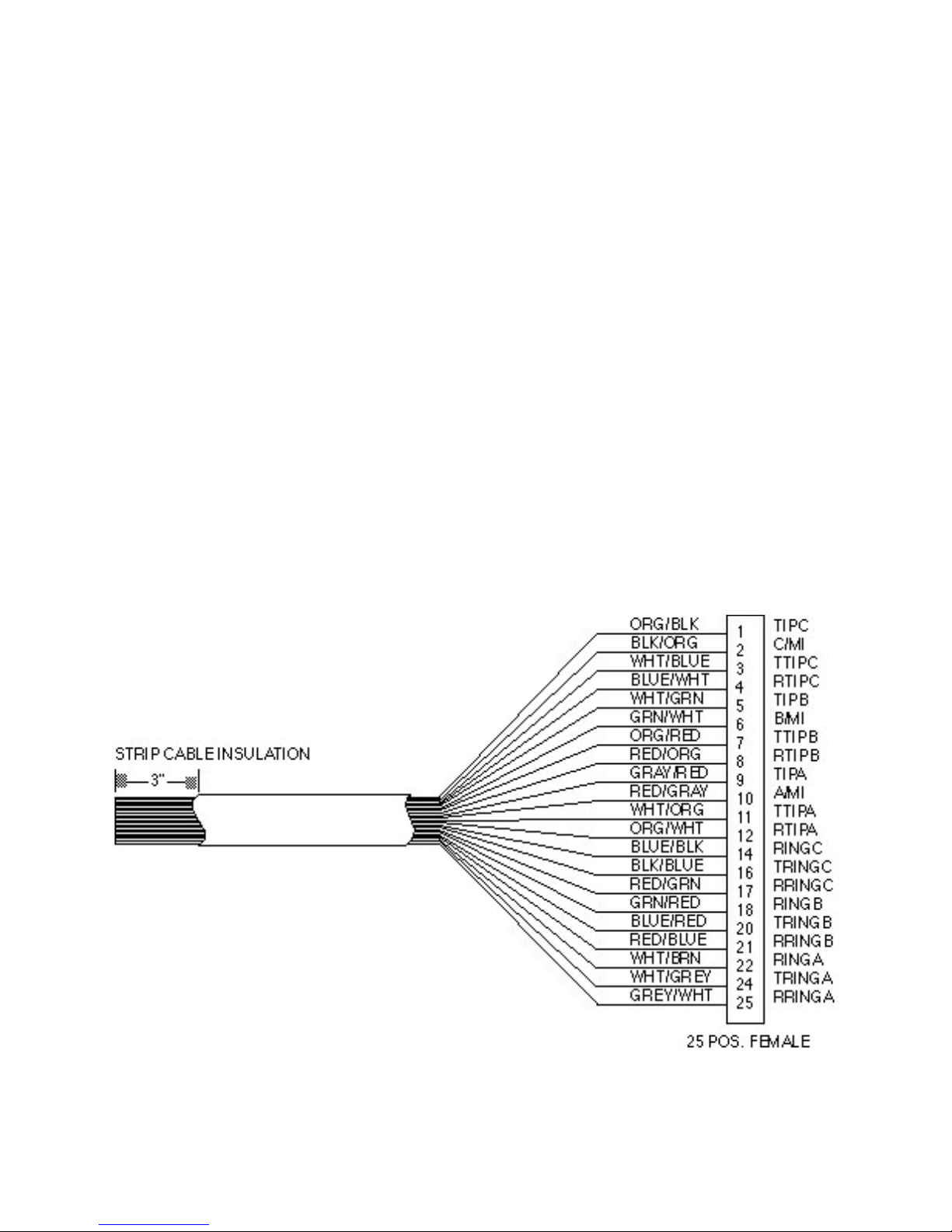
PN 88300150
1 1 Frame Ground 1
2 2 Transmit Data 2
3 3 Receive Data 3
4 4 Request to Send 4
55Clear to Send 5
6 6 Data Set Ready 6
7 7 Signal Ground 7
88Carrier Detect 8
99+ Voltage Test 9
12 12 High Speed 12
15 15 Transmit Clock 15
17 17 Receive Clock 17
20 20 Data Terminal Ready 20
22 22 Ring Indicator 22
25 25 Terminal Busy 25
Appendix I
Cable and Connector Pin Diagrams
RS232 Cable
25-pin Male Connector (DB25P type)
25-pin Female Connector (DB25S type) (on back of modem or CC216 rack)
Connects to Terminal or Computer RS232 Interface (serial port). Gender and pin-out depends on device.
4/3/01 97
Figure I-2. Line Cable
Page 98

PN 88300150
APPENDIX J
MULTI-TECH SYSTEMS’ ESCAPE METHODS
Introduction
You may find it necessary so met im es to is su e AT co mm and s to your mod e m whi le yo u are on-lin e with a
remote modem, without disconnecting the call. If so, you will want to take advantage of Escape methods
which allow you to change the modem’s mode of operation from On-Line mode to Command mode,
where you may issue AT commands, without disconnecting. While you may then return on-line, typically
most users escape so that they may hang up a modem upon completion of a call.
Our modems offer two Escape Methods: in-band, and out-of-band. Both incorporate Time Independent
Escape Sequence (TIES) methodology. An escape sequence is a pattern, or sequence, that the modem
recognizes as its signal to shift from On-Line mode to Command mode. Time Independent means that
the modem recognizes the escape sequence without a prefixed and/or suffixed delay.
In an in-band escape, the modem recognizes the escape sequence as a pattern sent to it as part of the
data stream or band (hence its name).
In an out-of-band escape, the escape sequence is a pattern that cannot and does not occur in the data
stream.
Our in-band escape method is: +++AT<CR>.
Our out-of-band escape method is: <BREAK>AT<CR>.
A BREAK signal cannot be se nt as part of a data file; in ste ad it is sent by a direct program comma nd to
the UART used by that computer.
BREAK is defined as either the transmission of binary 0 for a minimum of 10 bits; or as a minimum
interval of 135 milliseconds as established in the ITU-T X.28 standard. There are routines in high level
languages, and keys on most computers that have been established to send BREAK for fixed intervals,
but you may control the BREA K’s duration by refering to your UART’s specifications.
How to Select an Escape Method
If you want your modem to escape and then wait for you to issue a command before it will return to OnLine mode, then use +++AT<CR>. You might use this method if you find you need to review a help
screen in the middle of a communi cat io ns se s sion.
If you wish to combine the escape with a command (or commands) and with an immediate return to OnLine mode, then use the <BREAK>AT<CR> method. You may also use this method to have the modem
wait before it will return On-Line.
You may select your mode m ’s escape method by using an AT%E command.
The AT commands used to select the modem’s Escape Method are:
%E0 = Escape Disabled %E3 = Both escape methods enabled
%E1 = +++AT method (default) %E4 = Disable OK response to +++
%E2 = <BREAK>AT method %E5 = Enable OK response to +++
4/3/01 98
Page 99

PN 88300150
Escape Method 1: +++AT<CR>
In the following example, a user who is On-Line decides to set S0 Register to 1, to configure the modem
to answer on the first ring.
1. The user enters the sequence +++AT<CR> . The sequence is sent to the modem.
2. The modem transmits the +++.
3. The modem buffers AT and starts the Wait for <CR> timer.
4. Upon receiving the <CR> the modem escapes to Command mode.
5. The modem responds OK.
6. The user enters the command ATS0=1<CR>. This sequence is sent to the modem.
7. The modem buffers ATS0=1<CR> and identifies it as a valid command.
8. The modem executes the command, setting S0=1.
9. ATO<CR> is sent to the modem.
10. The modem returns to On-Line mode.
Escape Method 2: <BREAK>AT<CR>
In the following example, a user who is On-Line decides to set S-Registers S0 to 1, to configure the
modem to answer on the first ring.
1. The <BREAK> signal is sent to the modem.
2. The modem buffers <BREAK>.
3. The modem starts the S32 Wait for <CR> timer.
4. ATS0=1<CR> is sent to the modem.
5. The modem buffers ATS0=1<CR> and identifies it as a valid command.
6. The modem escapes to Command mode.
7. The modem executes the command, setting S0=1.
8. The modem returns to On-Line mode.
S-Registers and Escape Sequences
There are two S-Registers that you may set to modify the functioning of your escape sequences. The
first is S-Register S32, which establishes a value for how much time may elapse between the receipt of
the beginning of the escape sequence, whether <BREAK>AT, or +++AT, and the receipt of a <CR>.
This interval is known as Wait for <CR> Time, or BREAK passthru.
You may assign a value to S32 in increments of 100 milliseconds. The default value is 20, or 2 seconds.
In the +++AT<CR> method, the Wait for <CR> Time interval begins once the A in +++AT is received by
the modem.
In the <BREAK>AT method, the Wait for <CR> Time interval begins once the modem has received the
BREAK signal.
You may use S-Register S34 in conjunction with our in-band escape sequence, +++AT<CR>, to establish
the maximum number of characters that your modem can buffer following an “AT,” before a <CR> must
be received. The default value is 10 characters. Do not confuse this buffer size with our regular
Command mode buffer length of 60 characters.
S-Register S34 does not affect our out-of-band escape sequence’s buffer length, which is fixed at 60
characters.
4/3/01 99
Page 100

PN 88300150
Aborting an Escape Sequence
The +++AT<CR> escape will abort if you do not issue a <CR> before the Wait for <CR> Time interval
expires.
The <BREAK>AT<CR> method will also abort if yo u do not is sue a <CR > before the Wait for <CR> Time
interval expires, and also if any of the following occurs:
1. An illegal sequence is detected, in cl ud ing:
a) A character other than A follows the <BREAK>;
b) A character other than T follows <BREAK>A;
c) Two BREAKS are received in succession;
2. The command buffer overflows before a <CR> occurs.
If you have any questions about the information contained in this document, please direct them to:
Technical Support
c/o Multi-Tech Sys tem s, Inc.
2205 Woodale Drive
Mounds View, Minnesota 55112 USA
4/3/01 100
 Loading...