

Page 1

ModemModule
Model MT3334SMI Evaluation Kit
Data/Fax Socketed Modem
Developer ’s Guide
Page 2

Developer’s Guide
88312201 Revision B
ModemModule (Model MT3334SMI)
This publication may not be reproduced, in whole or in part, without prior expressed written permission from
Multi-Tech Systems, Inc. All rights reserved.
Copyright © 1999, by Multi-Tech Systems, Inc.
Multi-Tech Systems, Inc. makes no representations or warranties with respect to the contents hereof and
specifically disclaims any implied warranties of merchantability or fitness for any particular purpose.
Furthermore, Multi-Tech Systems, Inc. reserves the right to revise this publication and to make changes from
time to time in the content hereof without obligation of Multi-Tech Systems, Inc. to notify any person or
organization of such revisions or changes.
Record of Revisions
Revision Description
A Manual released. All pages at revision A.
(10/22/99)
B Added the &V command to the AT command set and added Appendix B which provides
(12/10/99) instructions for developing a customized flash prgramming utility . All pages at revision B.
Patents
This Product is covered by one or more of the following U.S. Patent Numbers: 5.301.274; 5.309.562;
5.355.365; 5.355.653; 5.452.289; 5.453.986. Other Patents Pending.
Trademarks
Trademarks of Multi-Tech Systems, Inc. are ModemModule and the Multi-Tech logo.
IBM is a registered trademark of International Business Machines Corporation.
Intel is a registered trademark of Intel Corporation.
MNP and Microcom Network Protocol are registered trademarks of Microcom, Inc.
Microsoft, Windows, Windows 95, and Windows NT are either registered trademarks or trademarks of Microsoft
Corporation in the United States and/or other countries.
Multi-Tech Systems, Inc.
2205 Woodale Drive
Mounds View , Minnesota 55112
(612) 785-3500 or (800) 328-9717
Fax 612-785-9874
Tech Support (800) 972-2439
Internet Address: http://www.multitech.com
Page 3

Contents
Chapter 1 - Introduction and Description
Introduction .......................................................................................................................................................6
Product Description...........................................................................................................................................6
Features ............................................................................................................................................................6
T echnical Specifications....................................................................................................................................7
Physical Dimensions .........................................................................................................................................9
Test/Demo Board Specifications .....................................................................................................................10
Test/Demo Board Block Diagram.............................................................................................................. 11
MT3334SMI Pin-out ........................................................................................................................................12
Typical Application ....................................................................................................................................13
MT3334SMI Design Considerations................................................................................................................14
Hardware Considerations .........................................................................................................................14
PC Board Layout Considerations................................................................................................. .............15
MT3334SMI Placement ............................................................................................................................16
T elecom Labeling Requirements...............................................................................................................17
Chapter 2 - AT Commands, S-Registers, and Result Codes
Introduction .....................................................................................................................................................20
S-Registers .....................................................................................................................................................28
Result Codes................................................................................................................................................... 30
Chapter 3 - Class 1 Fax Commands
Introduction .....................................................................................................................................................32
Class 1 Fax Command Summary ............................................................................................................. 32
Chapter 4 - Class 2 Fax Commands
Introduction .....................................................................................................................................................42
Class 2 Fax Command Implementation....................................................................................................42
Class 2 Fax Commands (EIA SP-2388 August 1990)...............................................................................42
Chapter 5 - Remote Configuration
Introduction .....................................................................................................................................................52
Basic Procedure..............................................................................................................................................52
Setup ........................................................................................................................................................52
Chapter 6 - Troubleshooting
Introduction .....................................................................................................................................................56
Local Analog Loopback Test (V.54 Loop 3)...............................................................................................56
Remote Digital Loopback Test (V.54 Loop 2)............................................................................................57
Local Digital Loopback Test (V.54 Loop 2)................................................................................................58
Chapter 7 - Upgrade Procedure
Introduction .....................................................................................................................................................60
Upgrade Overview ..........................................................................................................................................60
Step 1: Identify the Modem Firmware .......................................................................................................60
Step 2: Identify the Current Firmware Version..........................................................................................60
Step 3: Download the Upgrade File ..........................................................................................................61
Step 4: Extract the Upgrade Files.............................................................................................................62
Step 5: Clear Your Stored Paramenters ...................................................................................................62
Step 6: Use FlashPro to Upgrade Modem Firmware ................................................................................62
Step 7: Restore Your Parameters .............................................................................................................62
iii
Page 4

Appendixes
Appendix A - Regulatory Agency Compliance................................................................................................64
International Modem Restrictions .............................................................................................................65
EMC, Safety and Terminal Directive Compliance .................................................................................. ...66
European Directives User Guide Statement ............................................................................................. 66
New Zealand Telecom Warning Notice.....................................................................................................66
Appendix B - Multi-Tech Flash Programming Protocol...................................................................................67
Introduction ...............................................................................................................................................67
Intel Hex Format ....................................................................................................................................... 69
Index
iv
Page 5

Chapter 1 - Introduction and Description
Page 6
ModemModule Developer’s Guide
Introduction
The MT3334SMI socket modem provides a fully-integrated data and fax communications design for
communications over wide area networks using dial-up phone lines and the Internet.
This guide provides the Service Class 1 standard defining the commands that the developer can use
to configure and control a fax/data modem and the responses (result codes) that the fax/data modem
issues in response to the commands. This guide also provides the developer with specific Class 2 fax
command protocol used to control the sending and receiving of faxes.
Product Description
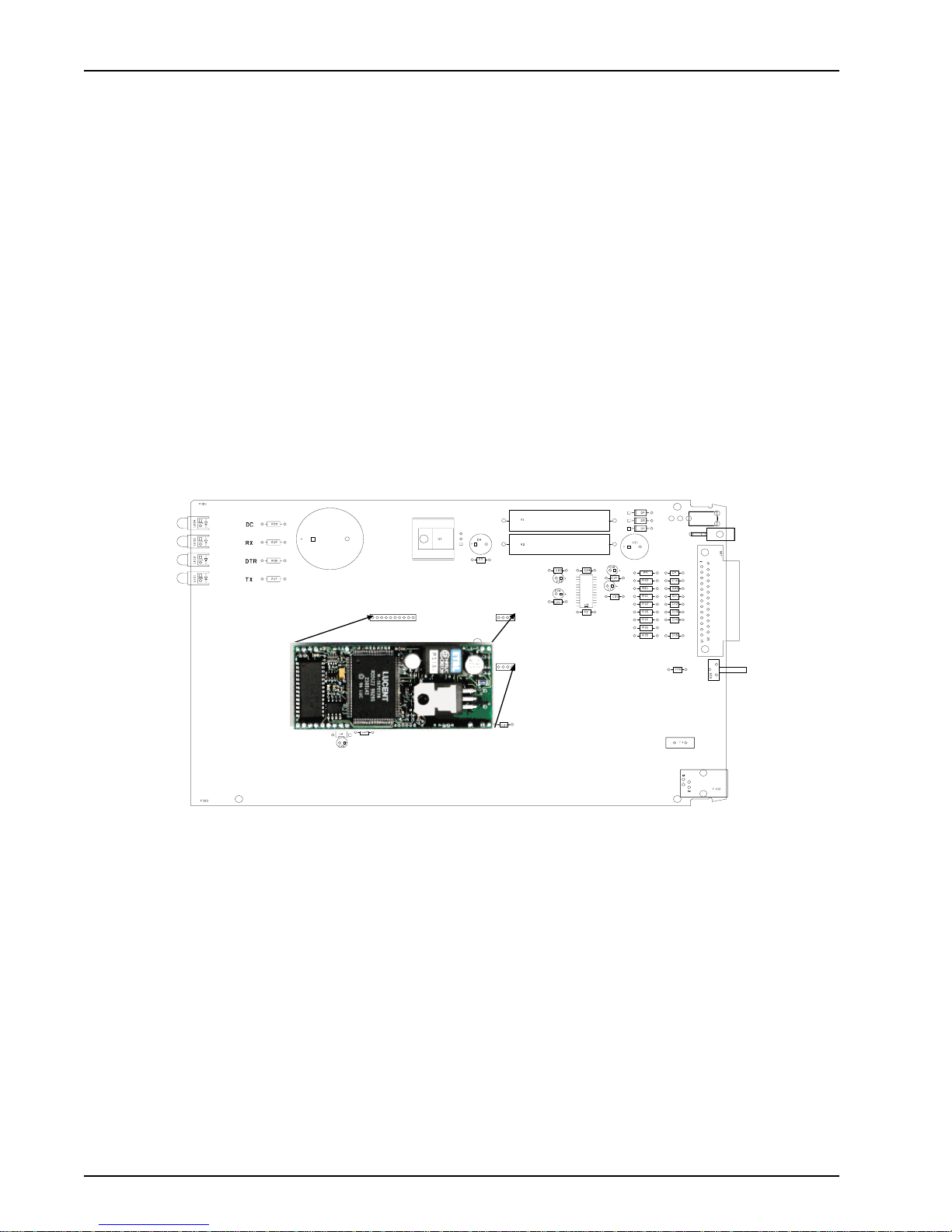
The MT3334SMI is a standard 64-pin Socket Modem (Figure 1-1 illustrates the MT3334SMI in
relationship to Multi-Tech’s Demo board) used for integrating data and fax communications. It
provides:
• Low power consumption
• A serial TTL level interface
• Full-featured fax and datacomm operation
• A very small footprint for embedded applications
Features
• Complete fax / modem solution: includes the controller, data pump, and DAA
• Modem downloads at 33.6 Kbps via enhanced V.34 server and uploads at 33.6 Kbps
LED 4
LED 3
LED 2
LED 1
(enhanced V .34)
DS1
J4
J5
J3
J6
Figure 1-1. MT3334SMI and Demo Board
S1
J7
J1
J2
• Supports V.42 error correction with V .42bis or MNP Class 5 data compression
• Supports industry-standard AT -style commands
• Standard TTL serial interface supporting DTE transfer speeds to 230.4 Kbps
• Remote configuration, diagnostic tests, Distinctive Ring, 3-number storage for automatic
dialing, and Flash memory for firmware updates.
• Includes NOVRAM for stored parameters
MT3334SMI6
Page 7

Technical Specifications
The ModemModule meets the following specifications:
Data Rates
Client-to-Server DataComm: supports enhanced V.34 (33.6K), V.32bis (14.4K), V.32 (9600), V.22bis
(2400), or slower speed connection for download speeds, and upload speeds to
33.6 Kbps via enhanced V.34.
Client-to-Client 33,600, 31,200, 28,800, 26,400, 24,000, 21,600, 19,200, 16,800, 14,400,
12,000, 9600, 7200, 4800, 2400, 1200, 0-300 bps
Fax Data Rates 14,400, 9600, 7200, 4800, 2400, 300 bps
Data Format Serial, binary, asynchronous
Modem Compatibility ITU-T V.34 enhanced, V.34, V.32bis, V.32, V.22bis, V.22; Bell 212A and 103/113;
ITU-T V.29, V.42, V.42bis; ITU-T V.21 & V.23 in international versions
Fax Compatibility ITU-T Group 3, Class 1 and 2, T.4, T.30, V.21, V.27ter, V.29, V.17, and TIA/
EIA TR29.2
Error Correction ITU-T V.42 (LAP-M or MNP 3–4)
Data Compression ITU-T V.42bis (4:1 throughput), MNP 5 (2:1 throughput)
Chapter 1 - Introduction and Description
Speed Conversion Serial port data rates adjustable to 300, 1200, 2400, 4800, 9600, 19,200,
38,400, 57,600, 115,200, and 230,400 bps
Modes of Operation Fax online modes; full duplex over dial-up lines; data mode, command mode,
and online command mode; V.54 Test mode.
Flow Control XON/XOFF (software), RTS/CTS (hardware)
Intelligent Features Fully AT command compatible; autodial, redial, repeat dial; pulse or tone dial;
dial pauses; auto answer; adaptive line probing; automatic symbol and
carrier frequency during start-up, retrain, and rate renrgotiation; DTMF detection;
call status display, auto-parity and data rate selections; keyboard-controlled modem
options; non-volatile memory; on-screen displays for modem option parameters;
command lines of up to 40 characters each; help menus; remote configuration;
DTR dialing.
Command Buffer 40 characters
Data Modulation FSK at 300 bps, PSK at 1200 bps, QAM at 2400, 4800, and 9600 bps (non-
trellis), QAM with trellis-coded modulation (TCM) at 9600, 12,000, 14,400,
16,800, 19,200, 21,600, 24,000, 26,400, 28,800, 31,200, and 33,600, bps
Fax Modulation V.21 CH2 FSK at 300 bps (half duplex)
V.27ter DPSK at 4800 and 2400 bps
V.29 QAM at 9600 and 7200 bps
V.17TCM at 14400, 12000, 9600, and 7200 bps
Carrier Frequencies 1600, 1646, 1680, 1800, 1829, 1867, 1920,
ITU-T V.34 1959, 2000 Hz
Carrier Frequencies 1800 Hz
ITU-T V.32bis/V.32
Carrier Frequencies Transmit originate: 1200 Hz
V.22bis/V.22 or Transmit answer: 2400 Hz
Bell 212A Standard Receive originate: 2400 Hz
(2400 & 1200 bps) Receive answer: 1200 Hz
MT3334SMI 7
Page 8

ModemModule Developer’s Guide
Carrier Frequencies Transmit originate: 390 Hz mark
ITU-T V.23 450 Hz space
(1200 bps) Receive originate: 1300 Hz mark
Transmit answer: 1300 Hz mark
Receive answer: 390 Hz mark
Carrier Frequencies Transmit originate: 980 Hz mark
ITU-T V.21 1180 Hz space
(0–300 bps) Receive originate: 1650 Hz mark
Transmit answer: 1650 Hz mark
Receive answer: 980 Hz mark
1180 Hz space
Carrier Frequencies Transmit originate: 1270 Hz mark
Bell 103/113 1070 Hz space
(0–300 bps) Receive originate: 2225 Hz mark
Transmit answer: 2225 Hz mark
Receive answer: 1270 Hz mark
2100 Hz space
2100 Hz space
450 Hz space
1850 Hz space
1850 Hz space
2025 Hz space
2025 Hz space
1070 Hz space
Fax Carrier V.21 Ch2 (half duplex):
Frequencies 1650 Hz mark, 1850 HZ space for transmit originate
1650 HZ mark, 1850 Hz space for transmit answer
V.27ter: 1800 Hz originate/answer
V.29 QAM: 1800 Hz originate/answer
V.17 TCM: 1800 Hz originate/answer
Transmit Level -11 dBm (dial-up)
Frequency Stability ±0.01%
Receiver Sensitivity -43 dBm under worst-case conditions
AGC Dynamic Range 43 dB
Interface Serial interface for EIA RS-232C/ITU-T V.24/V.28
Diagnostics Local analog loop, local digital loop, remote digital loop.
Weight 0.02 Kg. (0.04 lb.)
Dimensions: 1.045" × 2.541" × 0.680"
(2.7 x 6.5 x 1.8 cm)
Power consumption: Typical: 215 mA (1.3 W @ 5v DC)
Maximum: 420 mA (2.1 W @ 5.25v DC)
Environmental: 0-50° C; humidity range 20–90% (non-condensing)
Approvals*: UL 1950 approved
FCC Part 68 approved
Industry canada CS0s
EN60950
* Approvals are provided in controlled configurations and must be re-evaluated in end-user configurations.
MT3334SMI8
Page 9
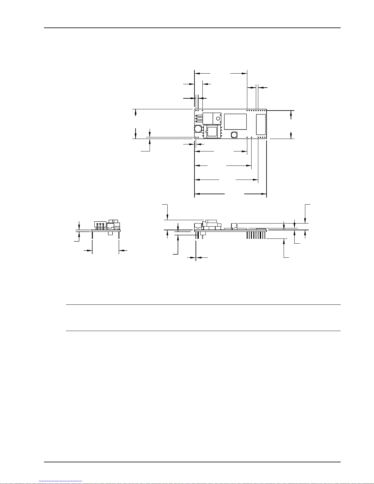
Physical Dimensions
Figure 1-2 illustrates the the physical dimensions of the MT3334SMI.
.286
[7,26]
.079
[2,01]
Chapter 1 - Introduction and Description
1.861
[47,27]
.079 TYP.
[2,01]
.062
[1,57]
1.045
[26,54]
.050
[1,27]
.945 REF.
[24]
MAXIMUM COMPONENT
HEIGHT SOLDER SIDE
Figure 1-2. MT3334SMI Physical Dimensions
.354
[8,99]
.118
[3]
.050
[1,27]
1.861
[47,27]
2.019
[51,28]
2.256
[57,3]
2.550
[64,77]
.020 ± .0002 SQUARE
[0,51]
.995
[25,27]
.228
[5,8]
.063
[1,6]
.310
[7,87]
CAUTION: If any component(s) is placed under the socket modem or if any component(s) should
extend to the point where part of it is under the socket modem, the component(s) must NOT exceed
.060 inches in height.
MT3334SMI 9
Page 10
ModemModule Developer’s Guide
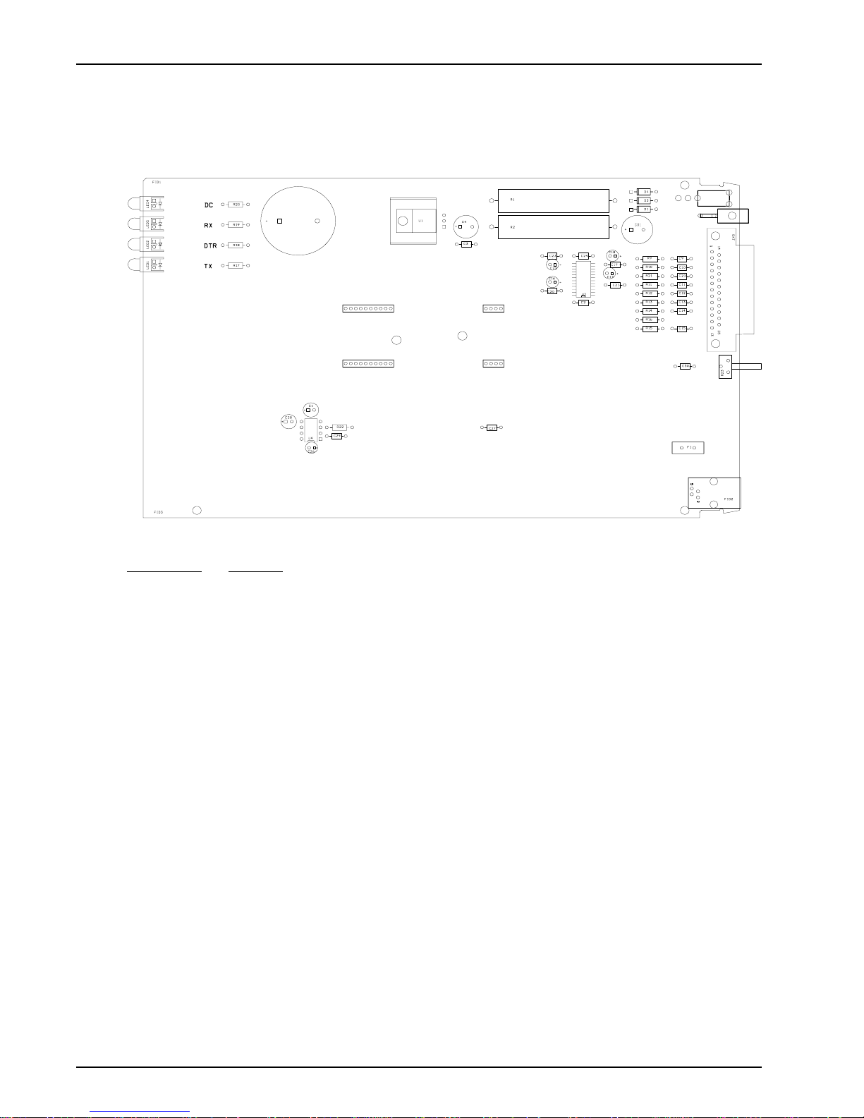
Test/Demo Board Specifications
The ModemModule Test/Demo Board kit includes a modem module, a power transformer for the test
board, and a diskette (this Developer’s Guide manual, etc.). Figure 1-3 illustrates the demo/test
board and Figure 1-4 illustrates the Test/Demo board block diagram.
LED 4
LED 3
LED 2
LED 1
DS1
Figure 1-4. MT3334SMI Test/Demo Board
Designation Function
DS1 Speaker
J1 25-Pos. DSUB
J2 6-Pin Mod. Jack (Line Jack)
J3, J6 4-Pos. Connector
J4, J5 10-Pos. Connector
J7 2-Pos. Header
LED1-LED4 Red LED
S1 SPST Switch
S1
J7
J1
J4
J5
J3
J6
J2
MT3334SMI10
Page 11
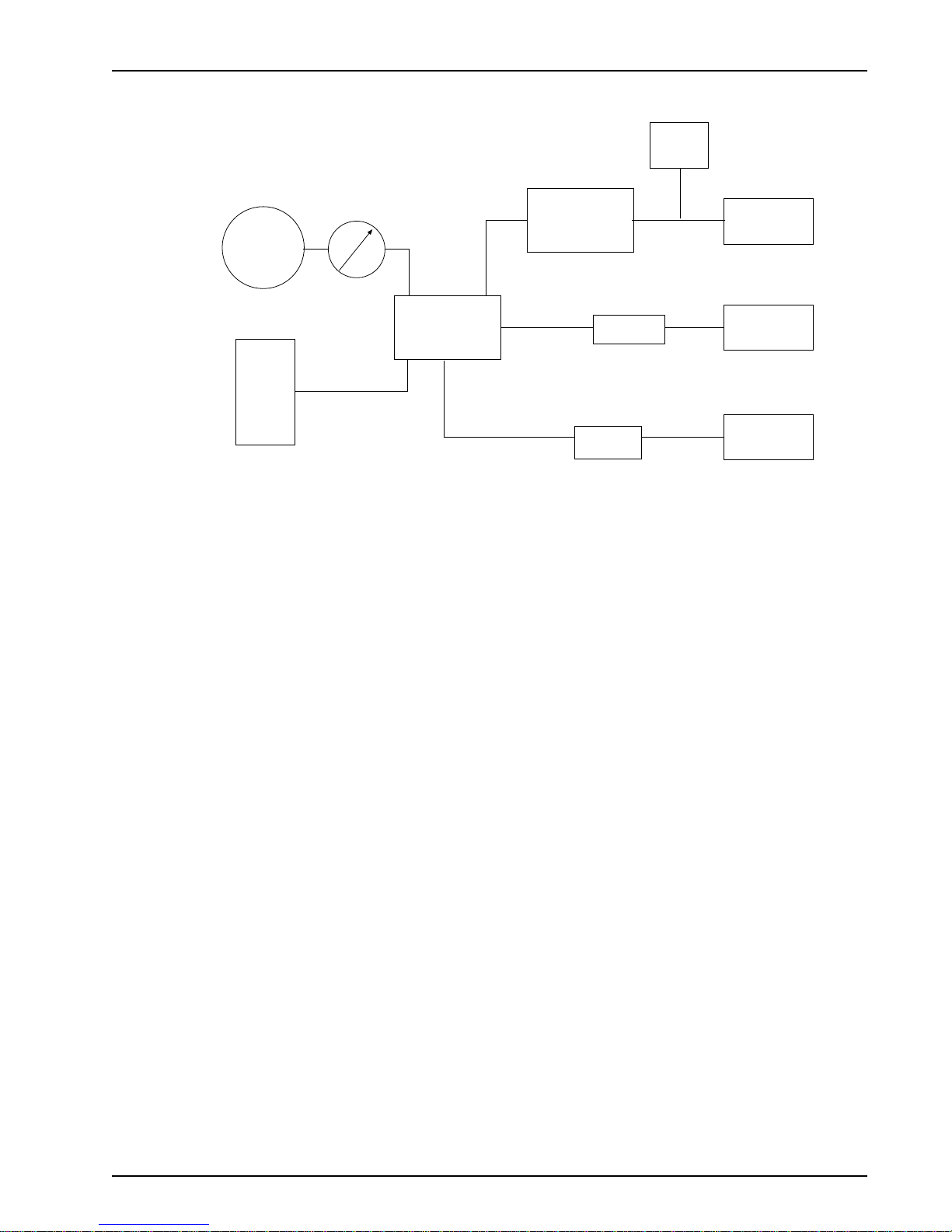
Test/Demo Board Block Diagram
Chapter 1 - Introduction and Description
Power
Switch
Speaker
DS1
LEDs
Power
Supply
Volume
Control
Socket
Modem
Transceiver
(RS-232)
Tip/Ring
Fuse
Figure 1-4. MT3334SMI Test/Demo Board Block Diagram
Power
Connector
DB-25
RS-232
RJ-11
Connector
MT3334SMI 11
Page 12
ModemModule Developer’s Guide
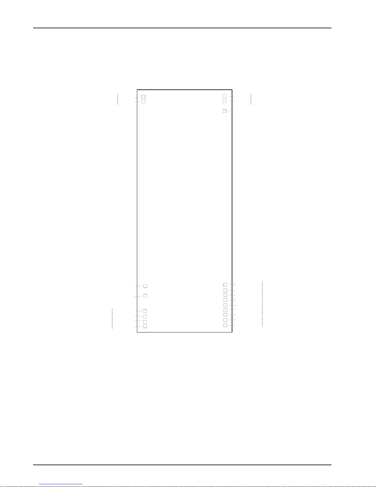
MT3334SMI Pin-out
The MT3334SMI uses a 20-pin interface to provide an on-board DAA with tip and ring connections,
audio circuit for call-progress monitoring, LED driver for call status annunciation, and serial interface
via TTL level signals.
DAA
Tip
Ring
1
2
64
63
61
SPKR
AGND
VCC
Audio
DLED
-RESET
DGND
DCDIND
RXIND
DTRIND
TXIND
24
26
29
30
31
32
41
40
39
38
37
36
35
34
33
Figure 1-5. MT3334SMI Pinout
DGND
-DTRTTL
-DCDTTL
-CTSTTL
-DSRTTL
-RITTL
-TXDTTL
-RXDTTL
-RTSTTL
Serial TTL
MT3334SMI12
Page 13

T ypical Application
The table below shows the MT3334SMI pinouts and Figure 1-6 illustrates a typical OEM application.
Pin # Circuit Type Signal Description Input/Output
Chapter 1 - Introduction and Description
1RJ
-11 Jack Tip Input/Output
2 RJ-11 Jack Ring Input/Output
26 External Call Status LEDs DGND
29 External Call Status LEDs DCD Output
30 External Call Status LEDs RX Output
31 External Call Status LEDs DTR Output
32 External Call Status LEDs TX Output
33 Serial TTL RTS Input
34 Serial TTL RXD Output
35 Serial TTL TXD Input
36 Serial TTL RI Output
37 Serial TTL DSR Output
38 Serial TTL CTS Output
39 Serial TTL DCD Output
40 Serial TTL DTR Input
41 Serial TTL DGND
61 Power VCC
63 Audio AGND
64 Audio SPKR
Speaker Driver
RJ-11
Jack
1 - x
2 - x
3
4
5 - x
6 - x
1
2
64
63
61
Circuitry
+5v DC Power
Call-status
LED
Circuitry
MT3334SMI 13
Digital Ground
Reset
24
26
29
30
31
32
41
40
39
38
37
UART
36
35
34
33
Figure 1-6. MT3334SMI T ypical OEM Application
Page 14
ModemModule Developer’s Guide
MT3334SMI Design Considerations
This section discusses hardware considerations, PC board layout considerations, and Telecom
labeling requirements.
Hardware Considerations
Disclaimer: Multi-Tech Systems makes no warranty claims for vendor product recommendations
listed below. Other vendor products may or may not operate satifactorily. Multi-Tech System’s
recommended vendor products only indicate that the product has been tested in controlled conditions
and were found to perform satisfactorily .
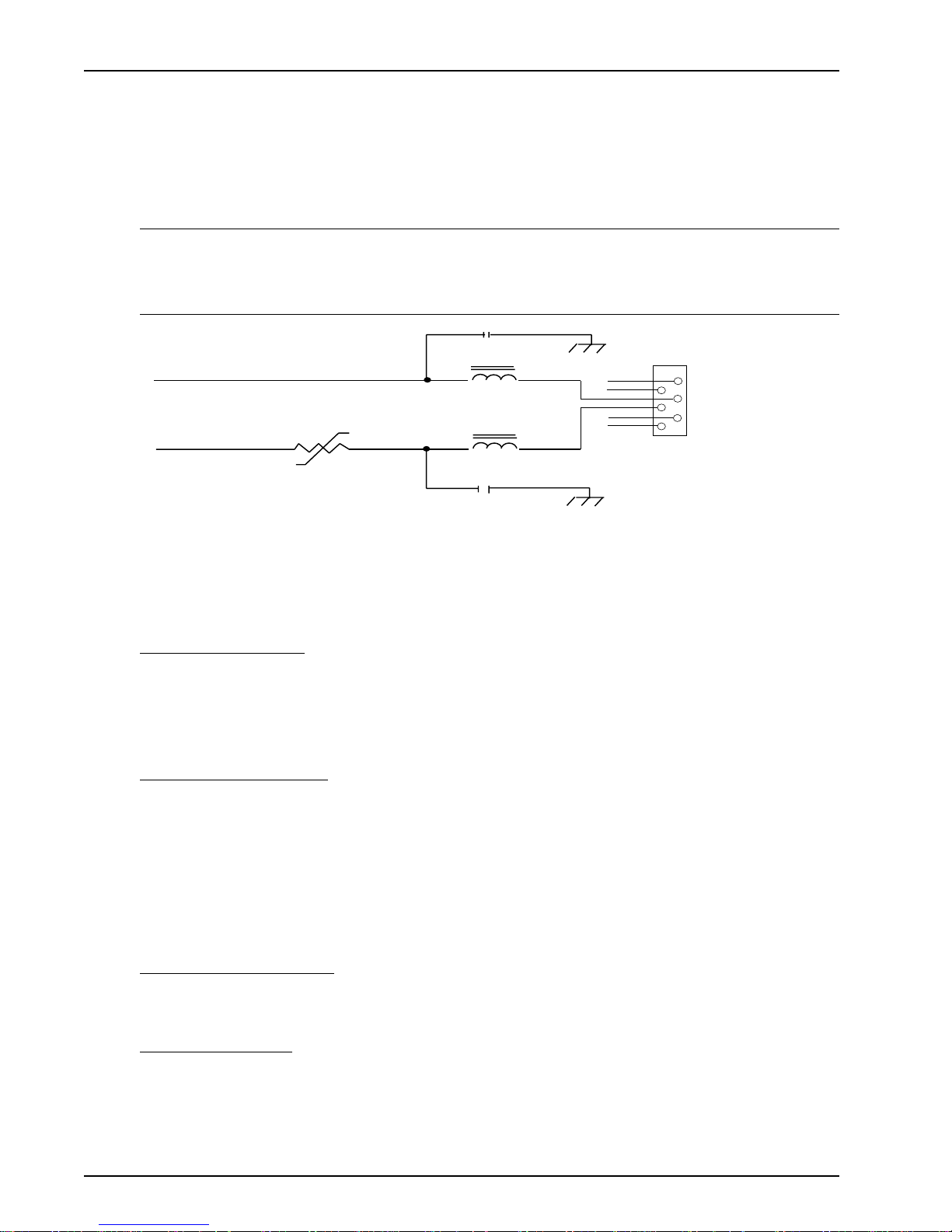
TIP
RING
C2
R1
TR600-150
FERRITE-600
C1
FB2
FERRITE-600
FB1
220PF/2KV
220PF/2KV
x
x
x
x
J1
6
5
4
3
2
1
Loaded 4 Pin Modjack
Figure 1-7. Tip and Ring Ferrite Connections
EMC: Surface mount ferrites are used on T&R (Tip and Ring) to mitigate emission levels out the RJ-
1 1 cable. 220pF capacitors are also used on T&R to reduce the common mode emissions that may
be present in certain systems. The ferrite and capacitors also aid in reducing the effects of transients
that may be present on the line.
Recommended Ferrite
Manufacturer – Associated Component Technology (ACT)
Part # - YCB-1206
Manufacturer – Murata Erie
Part # - BLM31A601SPT
Recommended Capacitor
Manufacturer – Murata Erie Manufacturer - Ever Grace Electronic Industrials
Part # - GHM3045X7R221K-GC(Surface mnt) Part # - YP221K2EA7PS
Part # - DE0807B221K-KH (Thru-hole device)
Note: The capacitors used on T&R must have a Y2 safety rating.
Telecom: The RJ-11 connector must meet FCC Part 68 requirements. Refer to FCC Part 68 section
68.500 subpart F for connector specifications. A self-healing fuse is used in series with line to help
prevent damage to the DAA circuit. This fuse is needed for FCC Part 68 compliance.
Recommended Connector
Manufacturer – Stewart
Part # - 6446S/RP-30
Recommended Fuse
Manufacturer – RayChem
Part # - TR600-150
Note: The fuse is also needed to meet UL1950 3rd edition protection against overvoltage from power
line crosses.
MT3334SMI14
Page 15

Safety: All creepages and clearances for the MT3334SMI have been designed to meet requirements
of safety standards EN60950 and IEC950. The requirements are based on a working voltage of
250V. When the recommended DAA circuit interface is implemented in a third party design all
creepage and clearance requirements must be strictly adhered to. The third party safety design
must be evaluated by the appropriate national agency per the required specification.
User accessible areas: Based on where the third party design is to be marketed/sold or used, it may
be necessary to provide an insulating cover over all TNV exposed areas. Consult with the
recognized safety agency to determine the requirements.
Notice: Even if the recommended design considerations are followed, there are no guarantees that
a particular system will comply with all the necessary regulatory requirements. It is imperative that
specific designs be completely evaluated by a qualified/recognized agency .
Recommended Transceiver
Manufacturer – Analog Devices
Part # - ADM207EAR
PC Board Layout Considerations
This section discusses the FCC Part 68 and Industry Canada CS-03 Telecom compliance of the
Multi-Tech Systems, Inc. Model MT5634SM/SMI socketed modem module.
Chapter 1 - Introduction and Description
This module was tested by the NVLAP accredited KTL Dallas Inc. laboratory and conforms to the
above said standards. The modem module was tested in the MultiTech MT ASR3-200, a 3-modem
asynchronous router that uses three socket modems for dial-up telephone access. The developer’s
guide (included on diskette) with the MT5634SM/SMI modem includes design specifications listing
recommendations for the RJ-1 1 phone jack and fuse which are needed for FCC Part 68 compliance.
The MTASR3-200 tested has sockets for three modem modules each having traces of varying
lengths out to the RJ-1 1 connectors. Trace lengths ranged from 1.97 to 3.15 inches. The trace widths
were all 12 mil. Since three ports with varying trace lengths were tested, we concluded that as long
as the customer’s printed circuit board characteristics are reasonably close to these parameters
there should not be any issues relating to telecom compliance. In addition to a recommended
external fuse, the modem module also has a Sidactor on board.
Multi-Tech believes that, provided the same components are used and parts placement is similar,
Telecom compliance will be maintained for the system and no additional testing is required.
Calculating Z for Tip and Ring Traces
Trace Impedance - Side-by-Side Traces
S
120
=
Z
o
Er
Where: Er = Relative permittivity of the PCB dielectric material. Typically 4 - 4.7
s = Spacing between traces - 12 mils (.012)
w = Trace width - 12 mils (.012)
t = Trace thickness - (.0022)
p
1n
w + t
120
=
Z
o
2.16
=
o
Z
54
W
Note: The trace inductance for the tested design varied from 61nH to 105nH.
MT3334SMI 15
1n
.03769
.0142
Page 16
ModemModule Developer’s Guide
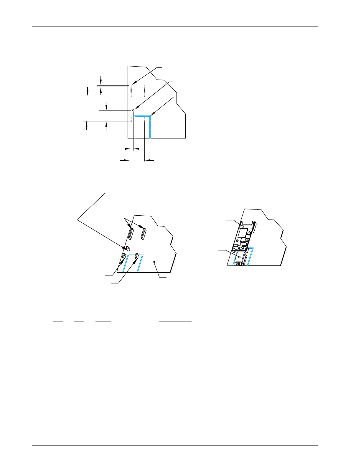
MT3334SMI Placement
Figure 1-8 illustrates where to place the MT3334SMI on a typical Motherboard. It must be placed so
that the analog end is near the phone jack.
.0787 TYP
[2]
1.732
[44]
.750
[19.05]
E (Digital)
.145
[3.683]
.945
[24.003]
B or C
Note: The locking end of C should
go in the Motherboard.
0.035 [0.889] Drill with 0.060 [1.524] Pad
0.125 [3.175] Non-Plated
A to D Barrier
(Shown for Reference Only)
F
G
D (Power and GND)
D (Analog)
A
Note: The modem should be placed with the
analog pins as close as possible to the line jack.
Figure 1-8: Placing the MT3334 SMI on a Typical Circuit Board
Key:
Qty Ref Name Description
1 A Reference Generic Motherboard
1 B or C Recommended RICHO DLMSP-4-01 Support Post
1 C or B Recommended RICHO MSP-4-01 Support Post
2 D Recommended 4-Pin 2mm SIP Socket (Thomas & Betts 42J2-04)
2 E Recommended 10-Pin 2mm SIP Socket (Thomas & Betts 42J2-10)
1 F Reference Socket Modem Assembly
1 G Reference Line Jack
MT3334SMI16
Page 17

Telecom Labeling Requirements
FCC regulations require labeling of registered Telephone and Data Terminal Equipment in
accordance with Part 68 Subpart D. There are two options available for labeling of the device
containing the MT5634SM modem module. The first option would be to use the registration number
assigned to Multi-Tech Systems, Inc. by the FCC as explained in Section 68.300 below and shown in
the sample label. The second option would be for the customer to submit applications for and use
their own registration number that would be assigned by the FCC. This would require a letter of
authorization for reregistration written by Multi-Tech Systems, Inc. giving the customer permission to
reregister the product. The customer would also need to obtain and file the necessary documents
and pay the required fees to the FCC.
Similarly, Industry Canada requires labeling in accordance with CS-03 requirements. Each modem
module includes an Industry Canada label that should be attached to the final product as described in
the Industry Canada CS-03 section below. Multiple Listing (similar to FCC’ s re-registration) is also
an option for Industry Canada labeling. Instructions are also detailed below.
FCC Part 68
(From FCC P AR T 68 Subpart D—Conditions for Registration)
Complete document available from US Government Printing Office:
http://www.access.gpo.gov/cgi-bin/cfrassemble.cgi?title=199847
Chapter 1 - Introduction and Description
Section 68.300 Labeling requirements.
(a) Registered terminal equipment and registered protective circuitry shall have prominently
displayed on an outside surface the following information in the following format:
Complies With Part 68, FCC Rules
FCC Registration Number: _____________
Ringer Equivalence: ____
(b) Registered terminal equipment and registered protective circuitry shall also have the following
identifying information permanently affixed to it.
(1) Grantee’s name.
(2) Model number, as specified in the registration application.
(3) Serial number or date of manufacture.
(4) Country of origin of the equipment: “Made in __________.”
Required if the equipment is not manufactured in the United States. (Country of origin shall
be determined in accordance with 19 U.S.C. 1304 and regulations promulgated thereunder.)
(5) As used herein, permanently affixed means that the required nameplate data is etched,
engraved, stamped, indelibly printed or otherwise permanently marked. Alternatively, the
required information may be permanently marked on a nameplate of metal, plastic, or other
material fastened to the enclosure by welding, riveting, or with a permanent adhesive. Such a
nameplate must be able to last for the expected lifetime of the equipment and must not be
readily detachable.
(6) When the device is so small or for such use that it is not practical to place the statements
specified in this section on it, the information required by paragraphs (a) and (b) of this
section shall be placed in a prominent location in the instruction manual or pamphlet supplied
to the user. The FCC Registration Number and the Model Number shall be displayed on the
device.
Sample: Complies With Part 68, FCC Rules
FCC Registration Number:
Ringer Equivalence
Multi-T ech Systems, Inc.
Model MT5634SM
S/N: xxxxxxx
MT3334SMI 17
AU7USA-25814-M5-5
Page 18

ModemModule Developer’s Guide
Reregistration
(From Form 730 Application Guide Appendix C-2) http://www.fcc.gov/formpage.html
Private label distributors may obtain a registration number in their own name. In this case, a
reregistration filing is made with the submission of Exhibit B, a copy of a letter from the original
registrant to the applicant giving permission for the reregistration and a willingness to provide the
applicant with any technical support. The applicant will replace the registration label on the original
grantee with the one containing the newly assigned registration number.
Industry Canada CS-03
Canadian regulations require that certified equipment bear an identifying certification label which is
obtained from Industry Canada. The label provided must be displayed on the equipment according to
Industry Canada specifications. http://spectrum.ic.gc.ca/~cert/
From Certification Procedure 01 (CP-01):
Certified equipment will bear an identifying certification label and the certificate holder will be
responsible for permanently affixing this certification label. The certification label identifies certified
equipment to the public, representatives of the telecommunications common carriers, the
Department, and other interested parties. The label must be permanently affixed to the equipment.
Multiple Listing
This terminal device may be multiple listed to other distributors based upon the approval granted to
the original certificate holder. In order to obtain a multiple listing certification, the following
documentation must be presented to Industry Canada:
(a) The model number , Industry Canada certificate number and certification number of the approved
equipment;
(b) a letter from the original certificate holder authorizing the Department to use information on file to
grant a multiple listing certification. The name / model number , certificate number and
certification number for the subject equipment must be shown. The letter must also declare that
the model to be multiple listed is identical in design and construction to the originally approved
model;
(c) a letter, from the proposed multiple listee, requesting the certification;
(d) a Terminal Equipment Certification / Testing Application and Agreement form, completed by the
proposed multiple listee;
(e) a drawing, sample or illustration of the product label; and
(f) payment in accordance with TRC-49 section on Multiple Listings.
MT3334SMI18
Page 19

Chapter 2 - AT Commands, S-Registers,
and Result Codes
Page 20

ModemModule Developer’s Guide
Introduction
The AT commands are used to control the operation of your modem. They are called AT commands
because each command must be preceded by the characters AT to get the ATtention of the modem.
A T commands can be issued only when the modem is in command mode or online command mode.
The modem is in command mode whenever it is not connected to another modem. The modem is in
data mode whenever it is connected to another modem and ready to exchange data. Online
command mode is a temporary state in which you can issue commands to the modem while
connected to another modem. To put the modem into online command mode from data mode, you
must issue an escape sequence (+++) followed immediately by the AT characters and the command,
e.g., +++ATH to hang up the modem. To return to data mode from online command mode, you must
issue the command ATO.
To send AT commands to the modem you must use a communications program, such as the
HyperTerminal applet in Windows 98/95 and NT 4.0, or some other available terminal program. You
can issue commands to the modem either directly , by typing them in the terminal window of the
communications program, or indirectly, by configuring the operating system or communications
program to send the commands automatically. Fortunately, communications programs make daily
operation of modems effortless by hiding the commands from the user . Most users, therefore, need to
use AT commands only when reconfiguring the modem, e.g., to turn autoanswer on or off.
The format for entering an AT command is ATXn, where X is the command and n is the specific value
for the command, sometimes called the command parameter. The value is always a number . If the
value is zero, you can omit it from the command; thus, AT&W is equivalent to AT&W0. Most
commands have a default value, which is the value that is set at the factory. The default values are
shown in the “A T Command Summary” (See below).
You must press ENTER (depending on the terminal program it could be some other key) to send the
command to the modem. Any time the modem receives a command, it sends a response known as a
result code. The most common result codes are OK, ERROR, and the CONNECT messages that the
modem sends to the computer when it is connecting to another modem. For a table of valid result
codes, see “Result Codes” at the end of this chapter.
You can issue several commands in one line, in what is called a command string. The command
string begins with AT and ends when you press ENTER. Spaces to separate the commands are
optional; they are ignored by the command interpreter. The most familiar command string is the
initialization string, which is used to configure the modem when it is turned on or reset, or when your
communications software calls another modem.
AT Command Summary
Command: AT Attention Code
Values: n/a
Description: The attention code precedes all command lines except A/, A:, and escape
Command: ENTER Key
Values: n/a
Description: Press the E
Command: A Answer
Values: n/a
Description: Answer call before final ring.
sequences.
NTER (RETURN) key to execute most commands.
Command: A/ Repeat Last Command
Values: n/a
Description: Repeat the last command string. Do not precede this command with AT. Do not
press E
NTER to execute.
MT3334SMI20
Page 21

Chapter 2 - AT Commands, S-Registers, and Result Codes
Command: Bn Communication Standard Setting
Values: n = 0–3, 15, 16
Default: 1 and 16
Description: B0 Select ITU-T V.22 mode when modem is at 1200 bps.
B1 Select Bell 212A when modem is at 1200 bps.
B2 Deselect V.23 reverse channel (same as B3).
B3 Deselect V.23 reverse channel (same as B2).
B15 Select V.21 when the modem is at 300 bps.
B16 Select Bell 103J when the modem is at 300 bps.
Command: Ds Dial
Values: s = dial string (phone number and dial modifiers)
Default: none
Description: Dial telephone number s, where s may up to 40 characters long and include the 0–9, *, #, A, B, C,
and D characters, and the L, P, T, V, W, S, comma (,), semicolon (;), !, @, ^ and $ dial string
modifiers.
Dial string modifiers:
L Redial last number. (Must be placed immediately after ATD.)
P Pulse-dial following numbers in command.
T Tone-dial following numbers in command (default).
V Switch to speakerphone mode and dial the following number. Use ATH command to hang up.
W Wait for a new dial tone before continuing to dial. (X2, X4, X5, X6, or X7 must be selected.)
, Pause during dialing for time set in register S8.
; Return to command mode after dialing. (Place at end of dial string.)
! Hook flash. Causes the modem to go on-hook for one-half second, then off-hook again.
@ Wait for quiet answer. Causes modem to wait for a ringback, then 5 seconds of silence, before
processing next part of command. If silence is not detected, the modem returns a NO ANSWER
code.
^ Disable data calling tone transmission.
$ Detect AT&T call card “bong” tone. The character should follow the phone number and precede
the user’s call card number: ATDT1028806127853500
$123456789
Command: DS=y Dial Stored Telephone Number
Values: n = 0–3
Default: none
Description: Dial a number previously stored in directory number y by the &Zy=x command.
Example: ATDS=3
Command: En Echo Command Mode Characters
Values: n = 0 or 1
Default: 1
Description: E0 Do not echo keyboard input to the terminal.
E1 Do echo keyboard input to the terminal.
Command: Fn Echo Online Data Characters
Values: n = 1
Default: 1
Description: F0 Enable online data character echo. (Not supported.)
F1 Disable online data character echo (included for backward compatibility with some software).
Command: Hn Hook Control
Values: n = 0 or 1
Default: 0
Description: H0 Go on-hook (hang up).
H1 Go off-hook (make the phone line busy).
MT3334SMI 21
Page 22

ModemModule Developer’s Guide
Command: In Information Request
Values: n = 0–5, 9, 11
Default: None
Description: I0 Display default speed and controller firmware version.
I1 Calculate and display ROM checksum (e.g., 12AB).
I2 Check ROM and verify the checksum, displaying OK or ERROR.
I3 Display default speed and controller firmware version.
I4 Display firmware version for data pump (e.g., 94).
I5 Display the board ID: software version, hardware version, and country ID
I9 Display the country code (e.g., NA Ve r. 1).
I11 Display diagnostic information for the last modem connection, such as DSP and firmware version,
link type, line speed, serial speed, type of error correction/data compression, number of past
retrains, etc.
Command: Ln Monitor Speaker Volume
Values: n = 0, 1, 2, or 3
Default: 2
Description: L0 Select low volume.
L1 Select low volume.
L2 Select medium volume.
L3 Select high volume.
Command: Mn Monitor Speaker Mode
Values: n = 0, 1, 2, or 3
Default: 1
Description: M0 Speaker always off.
M1 Speaker on until carrier signal detected.
M2 Speaker always on when modem is off-hook.
M3 Speaker on until carrier is detected, except while dialing.
Command: Nn Modulation Handshake
Values: n = 0 or 1
Default: 1
Description: N0 Modem performs handshake only at communication standard specified by S37 and the B
command.
N1 Modem begins handshake at communication standard specified by S37 and the B command.
During handshake, fallback to a lower speed can occur.
Command: On Return Online to Data Mode
Values: 0, 1, 3
Default: None
Description: O0 Exit online command mode and return to data mode (see +++AT<CR> escape sequence ).
O1 Issue a retrain and return to online data mode.
O3 Issue a rate renegotiation and return to data mode.
Command: P Pulse Dialing
Values: P, T
Default: T
Description: Configures the modem for pulse (non-touch-tone) dialing. Dialed digits are pulsed until a T
command or dial modifier is received.
Command: Qn Result Codes Enable/Disable
Values: n = 0 or 1
Default: 0
Description: Q0 Enable result codes.
Q1 Disable result codes.
Q2 Returns an OK for backward compatibility with some software.
Command: Sr=n Set Register Value
Values: r = S-register number; n varies
Default: None
Description: Set value of register Sr to value of n, where n is entered in decimal format. E.g., S0=1.
MT3334SMI22
Page 23

Chapter 2 - AT Commands, S-Registers, and Result Codes
Command: Sr? Read Register Value
Values: r = S-register number
Default: None
Description: Read value of register Sr and display it in 3-digit decimal form. E.g., S2? gives the response 043.
Command: T Tone Dialing
V alues: P, T
Default: T
Description: Configures the modem for DTMF (touch-tone) dialing. Dialed digits are tone dialed until a P
command or dial modifier is received.
Command: Vn Result Code Format
Values: n = 0 or 1
Default: 1
Description: V0 Displays result codes as digits (terse response).
V1 Displays result codes as words (verbose response).
Command: Wn Result Code Options
Values: n = 0, 1, or 2
Default: 2
Description: W0 CONNECT result code reports serial port speed, disables protocol result codes.
W1 CONNECT result code reports serial port speed, enables protocol result codes.
W2 CONNECT result code reports line speed, enables protocol result codes.
Command: Xn Result Code Selection
Values: n = 0–7
Default: 4
Description: X0 Basic result codes (e.g., CONNECT); does not look for dial tone or busy signal.
X1 Extended result codes (e.g., CONNECT 46000 V42bis); does not look for dial tone or busy signal.
X2 Extended result codes with NO DIALTONE; does not look for busy signal.
X3 Extended result codes with BUSY; does not look for dial tone.
X4 Extended result codes with NO DIALTONE and BUSY.
X5 Extended result codes with NO DIALTONE and BUSY.
X6 Extended result codes with NO DIALTONE and BUSY.
X7 Basic result codes with NO DIALTONE and BUSY.
Command: Zn Modem Reset
Values: n = 0 or 1
Default: None
Description: Z0 Reset modem to profile saved by the last &W command.
Z1 Same as Z0.
Command: &Cn Data Carrier Detect (DCD) Control
Values: n = 0 or 1
Default: 1
Description: &C0 Forces the DCD circuit to be always high.
&C1 DCD goes high when the remote modem’s carrier signal is detected, and goes low when the
carrier signal is not detected.
Command: &Dn Data Terminal Ready (DTR) Control
Values: n = 0, 1, 2, or 3
Default: 2
Description: &D0 Modem ignores the true status of the DTR signal and responds as if it is always on.
&D1 If DTR drops while in online data mode, the modem enters command mode, issues an OK, and
remains connected.
&D2 If DTR drops while in online data mode, the modem hangs up. If the signal is not present, the
modem will not answer or dial.
&D3 If DTR drops, the modem hangs up and resets as if an ATZ command were issued.
MT3334SMI 23
Page 24

ModemModule Developer’s Guide
Command: &Fn Load Factory Settings
Values: n = 0
Default: None
Description: &F0 Load factory settings as active configuration.
Note: See also the Z command.
Command: &Gn V.22bis Guard Tone Control
Values: n = 0, 1, or 2
Default: 0
Description: &G0 Disable guard tone.
&G1 Set guard tone to 550 Hz.
&G2 Set guard tone to 1800 Hz.
Note: The &G command is not used in North America.
Command: &Kn Flow Control Selection
Values: n = 0, 3, or 4
Defaults: 3
Description: &K0 Disable flow control.
&K3 Enable CTS/RTS hardware flow control.
&K4 Enable XON/XOFF software flow control.
Command: &Pn Pulse Dial Make-to-Break Ratio Selection
Values: n = 0, 1, or 2
Default: 0
Description: &P0 60/40 make-to-break ratio
&P1 67/33 make-to-break ratio
&P2 20 pulses per second
Note: The &P command is used only in Japan.
Command: &Qn Asynchronous Communications Mode
Values: n = 0, 5, 6, 8, or 9
Default: 5
Description: &Q0 Asynchronous with data buffering. Same as \N0.
&Q5 Error control with data buffering. Same as \N3.
&Q6 Asynchronous with data buffering. Same as \N0.
&Q8 MNP error control mode. If MNP error control is not established, the modem falls back according
to the setting in S36.
&Q9 V.42 or MNP error control mode. If neither error control is established, the modem falls back
according to the setting in S36.
Command: &Sn Data Set Ready (DSR) Control
Values: n = 0 or 1
Default: 0
Description: &S0 Force DSR always high (on).
&S1 Let DSR go high only during a connection.
at power-on or following the ATZ command.
Command: &V Display Current Settings
Values: n/a
Description: Displays the active modem settings, including the callback security settings if callback security is
enabled. If the setup password has been entered, it also displays the callback security passwords.
Command: &Wn Store Current Configuration
Values: n = 0
Default: 0
Description: &W0 Stores current modem settings in non-volatile memory and causes them to be loaded at power-on
or following the ATZ command instead of the factory defaults. See also the &F command.
&W1 Clears user default settings from non-volatile memory and causes the factory defaults to be
loaded at power-on or following the ATZ command.
MT3334SMI24
Page 25

Chapter 2 - AT Commands, S-Registers, and Result Codes
Command: &Zy=x Store Dialing Command
Values: y = 0–3 (callback security disabled) or 0–29 (callback security enabled)
x = Dialing command
Default: None
Description: Stores dialing command x in memory location y. Dial the stored number using the command
ATDS=y. See also the #CBSn command. For callback security options, see Chapter 6.
Command: \An Select Maximum MNP Block Size
Values: n = 0, 1, 2, or 3
Default: 3
Description: \A0 64-character maximum.
\A1 128-character maximum.
\A2 192-character maximum.
\A3 256-character maximum.
Command: \Bn Transmit Break
Values: n = 0–9 in 100 ms units
Default: 3
Description: In non-error-correction mode only, sends a break signal of the specified length to a remote
modem. Works in conjunction with the \K command.
Command: \Jn Data Buffer Control
Values: n = 0
Default: 0
Description: \J0 Enable data buffer—serial port speed is independent of connect speed.
\J1 Disable data buffer—serial port speed is forced to the line speed.
Command: \Kn Break Control
Values: n = 0–5
Default: 5
Description: Controls the response of the modem to a break received from the computer, the remote modem,
or the \B commnd. The response is different for each of three different states.
Data mode. The modem receives the break from the computer:
\K0 Enter online command mode, no break sent to the remote modem.
\K1 Clear data buffers and send break to the remote modem.
\K2 Same as \K0.
\K3 Send break immediately to the remote modem .
\K4 Same as \K0.
\K5 Send break to the remote modem in sequence with the transmitted data.
Data mode. The modem receives the break from the remote modem:
\K0 Clear data buffers and send break to the computer.
\K1 Same as \K0.
\K2 Send break immediately to the computer.
\K3 Same as \K2.
\K4 Send break to the computer in sequence with the received data.
\K5 Same as \K4.
Online command mode. The modem receives a \Bn command from the computer:
\K0 Clear data buffers and send break to the remote modem.
\K1 Same as \K0.
\K2 Send break immediately to the remote modem.
\K3 Same as \K2.
\K4 Send break to the remote modem in sequence with the transmitted data.
\K5 Same as \K4.
MT3334SMI 25
Page 26

ModemModule Developer’s Guide
Command: \Nn Error Correction Mode Selection
Values: n = 0–5, or 7
Default: 3
Description: \N0 Non-error correction mode with data buffering (buffer mode; same as &Q6).
\N1 Direct mode.
\N2 MNP reliable mode. If the modem cannot make an MNP connection, it disconnects.
\N3 V.42/MNP auto-reliable mode. The modem attempts first to connect in V.42 error correction mode,
then in MNP mode, and finally in non-error-correction (buffer) mode with continued operation.
\N4 V.42 reliable mode.If the modem cannot make a V.42 connection, it disconnects.
\N5 V.42, MNP, or non-error correction (same as \N3).
\N7 V.42, MNP, or non-error correction (same as \N3).
Command: \Qn Flow Control Selection
Values: n = 0, 1, or 3
Default: 3
Description: \Q0 Disable flow control (same as &K0).
\Q1 XON/XOFF software flow control (same as &K4).
\Q2 CTS-only flow control. Not supported.
\Q3 RTS/CTS hardware flow control (same as &K3).
Command: \Tn Inactivity Timer
Values: n = 0, 1–255
Default: 0
Description: \Tn Sets the time (in minutes) after the last character is sent or received that the modem waits before
disconnecting. A value of zero disables the timer. Applies only in buffer mode.
Note: You can also set the inactivity timer by changing the value of S30.
Command: \Vn Protocol Result Code
Values: n = 0, 1, or 2
Default: 1
Description: \V0 Disable the appending of the protocol result code to the DCE speed.
\V1 Enable the appending of the protocol result code to the DCE speed.
\V2 Same as \V1.
Command: \Xn XON/XOFF Pass-Through
Values: n = 0 or 1
Defaults: 0
Description: \X0 Modem responds to and discards XON/XOFF characters.
\X1 Modem responds to and passes XON/XOFF characters.
Command: -Cn Data Calling Tone
Values: n = 0 or 1
Defaults: 0
Description: -C0 Disable V.25 data calling tone to deny remote data/fax/voice discrimination.
-C1 Enable V.25 data calling tone to allow remote data/fax/voice discrimination.
Command: %B View Numbers in Blacklist
Values: n/a
Description: If blacklisting is in effect, AT%B displays the numbers for which the last call attempted in the
previous two hours failed. In countries that do not require blacklisting, the ERROR result code
appears.
Command: %Cn Data Compression Control
Values: n = 0 or 1
Default: 1
Description: %C0 Disable V.42bis/MNP 5 data compression.
%C1 Enable V.42bis/MNP 5 data compression.
MT3334SMI26
Page 27

Chapter 2 - AT Commands, S-Registers, and Result Codes
Command: %DCn AT Command Control
Values: n = 0 or 1
Default: 0
Description: %DC0 The modem responds to AT commands.
%DC1 The modem ignores AT commands.
Note: The modem will respond to AT%DC for 10 seconds after power-up.
Command: %En Fallback and Fall Forward Control
Values: n = 0, 1, or 2
Default: 2
Description: %E0 Disable fallback and fall forward.
%E1 Enable fallback, disable fall forward.
%E2 Enable fallback and fall forward.
Command: $Dn DTR Dialing
Values: n = 0 or 1
Default: 0
Description: $D0 Disables DTR dialing.
$D1 Dials the number in memory location 0 when DTR goes high.
Command: +ES=n Enable Synchronous Buffered Mode
Values: n = 6
Default: None
Description: Allows an H.324 video application direct access to the synchronous data channel. On underflow,
the modem sends HDLC flag idle (0x7E) to the remote modem.·This special error control mode is
overridden by any of the following commands: &F, &M, &Q, or \N.
AT+ES=? shows the only allowed value.
AT+ES? shows the current value.
Command: #Sx Enter Setup Password
Values: x= password (1–8 characters, case sensitive)
Default: MTSMODEM
Description: Enters the remote configuration setup password.
Command: #S= x Store Setup Password
Values: x= password (1–8 characters, case sensitive)
Default: MTSMODEM
Description: Stores a new remote configuration setup password.
Command: +++AT<CR> Escape Sequence
Values: n/a
Description: Puts the modem in command mode (and optionally issues a command) while remaining online.
Type +++AT and up to ten command characters, then press ENTER. Used mostly to issue the
hang-up command: +++ATH<CR>.
Command: %%%AT<CR>Remote Configuration Escape Sequence
Values: n/a
Description: Initiates remote configuration mode while online with remote modem. The remote configuration
escape character (%) is defined in register S13.
MT3334SMI 27
Page 28

ModemModule Developer’s Guide
S-Registers
Certain modem values, or parameters, are stored in memory locations called S-registers. Use the S
command to read or to alter the contents of S-registers (see previous section).
Register Unit Range Default Description
S0 1 ring 0, 1–255 1 Sets the number of rings until the modem answers. ATS0=0
S1 1 ring 0–255 0 Counts the rings that have occurred.
S2 decimal 0–127 43 (+) Sets ASCII code for the escape sequence character.
128–255 Values greater than 127 disable escape.
S3 decimal 0–127 13 (^M) Sets the ASCII code for the carriage return character.
S4 decimal 0–127 10 (^J) Sets the ASCII code for the line feed character.
S5 decimal 0–32 8 (^H) Sets the ASCII code for the backspace character.
33–127 Values greater than 32 disable backspace.
S6 seconds2–65* 2* Sets the time the modem waits after it goes off-hook before it
S7 seconds1–255* 50 * Sets the time the modem waits for a carrier signal before aborting
S8 seconds0–65 2 Sets the length of a pause caused by a comma character in a
S9 decimal 0, 1–127 37 (%) Sets ASCII code for remote configuration escape character. S9=0
S10 100 ms 1–254 20 Sets how long a carrier signal must be lost before the modem
S11 1 ms 50–150* 95* Sets spacing and duration of dialing tones.
S28 decimal 0, 1–255 1 0 disables, 1–255 enables V.34 modulation.
S30 1 minute0, 1–255 0 Sets the length of time that the modem waits before disconnecting
S35 decimal 0–1 0 0 disables, 1 enables the V.25 data calling tone, which allows
S36 decimal 0–7 7 Specifies the action to take in the event of a negotiation failure
S37 decimal 0–19 0 Sets the maximum V.34 “upstream” speed at which the modem
disables autoanswer completely.
begins to dial the telephone number.
a call. Also sets the wait for silence time for the @ dial modifier.
dialing command.
disables remote configuration.
disconnects.
when no data is sent or received. A value of zero disables the
timer. See also the \T command
remote data/fax/voice discrimination.
when error control is selected. (See S48.)
attempts to connect.
0 = maximum modem speed
1 = reserved
2 = 1200/75 bps
3 = 300 bps
4 = reserved
5 = 1200 bps
6 = 2400 bps
7 = 4800 bps
8 = 7200 bps
9 = 9600 bps
10 = 12000 bps
11 = 14400 bps
12 = 16800 bps
13 = 19200 bps
14 = 21600 bps
15 = 24000 bps
16 = 26400 bps
17 = 28800 bps
18 = 31200 bps
19 = 33600 bps
MT3334SMI28
Page 29

Chapter 2 - AT Commands, S-Registers, and Result Codes
S43 decimal 0–1 1 For testing and debugging only. Enables/disables V.32bis start-up auto mode
operation. 0 = disable; 1 = enable.
S48 decimal 7 or 128 7 Enables (7) or disables (128) LAPM negotiation. The following table lists the S36
and S48 configuration settings for certain types of connections.
S48=7 S48=128
S36=0, 2
S36=1, 3
S36=4, 6
S36=5, 7
LAPM or hangup Do not use
LAPM or async Async
LAPM, MNP, or hangup MNP or hangup
LAPM, MNP, or aysnc
MNP or async
S89 seconds 0, 5–25510 Sets the length of time in the off-line command mode before the modem goes into
standby mode. A value of zero prevents standby mode; a value of 1–4 sets the
value to 5.
MT3334SMI 29
Page 30

ModemModule Developer’s Guide
Result Codes
In command mode your modem can send responses called result codes to your computer. Result
codes are used by communications programs and can also appear on your monitor.
Terse Verbose Description
0OK Command executed
1 CONNECT Modem connected to line
2 RING Ring signal detected
3 NO CARRIER Carrier signal lost or not detected
4 ERROR Invalid command
5 * CONNECT 1200 Connected at 1200 bps
6 NO DIALTONE No dial tone detected
7 BUSY Busy signal detected
8 NO ANSWER No answer at remote end
10* CONNECT 2400 Connected at 2400 bps
1 1* CONNECT 4800 Connected at 4800 bps
12* CONNECT 9600 Connected at 9600 bps
13* CONNECT 14400 Connected at 14400 bps
14* CONNECT 19200 Connected at 19200 bps
24* CONNECT 7200 Connected at 7200 bps
25* CONNECT 12000 Connected at 12000 bps
26* CONNECT 16800 Connected at 16800 bps
40* CONNECT 300 Connected at 300 bps
55* CONNECT 21600 Connected at 21600 bps
56* CONNECT 24000 Connected at 24000 bps
57* CONNECT 26400 Connected at 26400 bps
58* CONNECT 28800 Connected at 28800 bps
59* CONNECT 31200 Connected at 31200 bps
60* CONNECT 33600 Connected at 33600 bps
88 DELAYED Delay is in effect for the dialed number
89 BLACKLISTED Dialed number is blacklisted
90 BLACKLIST FULL Blacklist is full
* EC is added to these result codes when the extended result codes configuration option is enabled. EC is
replaced by one of the following
codes, depending on the type of error control connection:
V42bis —V .42 error control (LAP-M) and V.42bis data compression
V42 —V.42 error control (LAP-M) only
MNP5 —MNP 4 error control and MNP 5 data compression
MNP4 —MNP 4 error control only
NoEC —No error control protocol).
MT3334SMI30
Page 31

Chapter 3 - Class 1 Fax Commands
Page 32

ModemModule Developer’s Guide
Introduction
The Service Class 1 standard (EIA/TIA-578) defines the commands that a PC user may issue to
configure and control a fax/data modem, and the responses (result codes) that the fax/data modem
may issue in response to those commands.
The Class 1 standard provides the basic services needed to support Group 3 fax operation. Support
of the 1988 CCITT (ITU-T) T.30 recommended procedures for session management and the T .4
recommendation for image data handling are required at the PC.
Service Class 1 provides the following services (as required, or optional in Group 3 facsimile
operation):
• Connection (originate and answer),
• Waiting and silence detection,
• Data transmission and reception (data transfer),
• HDLC (High-level Data Link Control) data framing/transparency/error detection, and
• Message generation/response.
HDLC is an ISO standard, bit-oriented data communications protocol. HDLC control information is
consistently placed, and specific control bit patterns are considerably different than those used as
data, providing a largely error-free protocol.
Class 1 Fax Command Summary
The ModemModule Fax Class 1 enhancements are implemented with six AT+F (for Fax) commands.
The +FTM, +FRM, +FTH, and +FRH commands must be entered as the last command in the
command string (i.e., the last command on the command line). The +FTS and the +FRS commands
can be entered anywhere in the command string.
Command Description
+FCLASS? Display Current Class
+FCLASS=? Display Service Class Capabilities
+FCLASS=<> Select Service Class
+FTS=<time> Stop tranmission and pause (10 ms intervals, 0-255)
+FTS=? Display the valid +FTS=<time> range (0-255)
+FRS=<time> Wait for silence (10 ms intervals, 0-255)
+FRS=? Display the valid +FRS=<time> range
+FTM=<MOD> Transmit data with specified <MOD> carrier
+FTM=? Display the valid +FTM=<MOD> carrier range
+FRM=<MOD> Receive data with specified <MOD> carrier
+FRM=? Display the valid +FRM=<MOD> carrier range
+FTH=<MOD> Transmit HDLC data with specified <MOD> carrier
+FTH=? Display the valid +FTH=<MOD> carrier range
+FRH=<MOD> Receive HDLC data with specified <MOD> carrier
+FRH=? Display the valid +FRH=<MOD> carrier range
If entering multiple commands on the command line, use semicolons between commands. These +F
commands are defined in the following sections. The <MOD> parameter may take on the following
values.
MT3334SMI32
Page 33

Chapter 3 - Class 1 Fax Commands
T able 3-1. Fax MOD (Modulation) Parameter Values
Value Modulation Speed (bps) Requirements
3 V.21 ch.2 300 required for +FTH & +FRH
24 V.27ter 2400 required for +FTM & +FRM
48 V.27ter 4800 required for +FTM & +FRM
72 V.29 7200 optional
73 V.17 7200 optional
74 V.17 w/st 7200 optional
96 V.29 9600 optional
97 V.17 14400 optional
98 V.17 w/st 14400 optional
121 V.17 or V.33 12000 optional
122 V.17 w/st 12000 optional
145 V.17 or V.33 14400 optional
146 V.17 w/st 14400 optional
All other codes are reserved. "V.17 w/st" indicates V.17 short training (aka, "quick train"). All of the
above commands return an ERROR result code if entered when the ModemModule is on-hook.
Use the command syntax +<command>=? to ask for the valid range of values supported. For
example, if you entered +FTH=?, the Class 1 ModemModule would return 3 (a Class 2
ModemModule would return 3,24,48,72,73, 74, 96).
Command: +FCLASS? <Enter>
Function: Display Current Class
Values: 0, 1, 2
Default: 0 (data modem)
Result Codes: OK if the command is accepted; ERROR if the parameter value is out of range.
Description: +FCLASS? requests the current Service Class of the ModemModule, as shown
below.
Result Code Meaning
0 indicates a data modem
1 indicates a Service Class 1 (fax/data) modem
2 indicates a non-standard Class 2 modem (based on an early draft of the Class 2.0
standard).
Command: +FCLASS=? <Enter>
Function: Display Service Class Capabilities
Values: 0, 1 (other values are reserved)
Default: 0 (data modem)
Result Codes: OK if the command is accepted; ERROR if the parameter value is out of range.
Description: The +FCLASS=? command displays the set of Service Classes supported by the
modem from the list of values (e.g., 0,1 for a modem that supports data
communications plus fax Service Class 1). This command returns the service class
or classes available with the modem. The modem returns a list of all supported
values, separated by commas if more than one class is supported. For example, a
modem that supports data communications and Class 1 fax would respond with
"0,1".
MT3334SMI 33
Page 34

ModemModule Developer’s Guide
Command: +FCLASS=<value> <Enter>
Function: Select Service Class
Values: 0, 1, 2
Default: 0 (data mode)
Result Codes: OK if the command is accepted; ERROR if the parameter value is out of range.
Description: This command configures the Service Class for the modem.
The command options are:
+FCLASS=0 Select Data mode
+FCLASS=1 Select Fax Class 1 operation
+FCLASS=2 Select Fax Class 2 operation
Example: To configure the modem for Class 1 fax operation, enter the command AT+FCLASS=1
and hit Enter. The modem will then accept Class 1 commands.
Command: +FTS=<time> <Enter>
Function: Stop T ransmission and Wait
Values: <time> = 0-255 in 10 ms intervals
Default: 0
Result Codes: OK if the command is accepted; ERROR if the parameter value is out of range.
Description: The +FTS= command causes the modem to stop any transmission, then wait for the
amount of time specified by <time>, then send an OK result code to the PC. If this
command is entered with the modem on-hook, the ERROR result code is displayed.
The main function of +FTS is to enforce the 75+/-20 ms of silent time needed
between modulation changes.
Note: The +FTS= command can be entered anywhere in the command string.
Command: +FTS=? <Enter>
Function: Display the wait-for-silent time range
Values: <time> = 0-255 in 10 ms intervals
Default:0
Result Codes: the current range of values supported by the modem.
Description: The +FTS=? command causes the modem to display the valid (supported) range of
time intervals specified by the +FTS=<time> command.
Command: +FRS=<time> <Enter>
Function: Stop T ransmission and Wait
Values: <time> = 0-255 in 10 ms intervals
Default: 0
Result Codes: OK if the command is accepted; ERROR if the parameter value is out of range.
Description: The +FRS= command causes the modem to listen for a specified amount of silence
on the line, then display an OK result code when silence has been present on the
line for the amount of time specified. The value <time> is in 10 millesecond intervals.
The command terminates when either the specified amount of silent time has been
detected, or when the PC sends the modem another character (which is discarded).
The modem returns the OK result code in either case. If this command is entered
with the modem on-hook, the ERROR result code is displayed. The main function of
the +FRS= command is to determine when it is safe to reverse the line and start
transmitting.
Note: The +FRS= command can be entered anywhere in the command string.
MT3334SMI34
Page 35

Chapter 3 - Class 1 Fax Commands
Command: +FRS=? <Enter>
Function: Display the range of stop-transmission-and-wait period values
Values: <time> = 0-255 in 10 ms intervals
Default:0
Result Codes: the current range of values supported by the modem.
Description: The +FRS=? command causes the modem to display the current set of stop-
transmission-and-wait period values supported (specified by the +FRS=<time>
command).
Command: +FTM=<MOD> <Enter>
Function: Transmit data with <MOD> carrier
Values: <MOD> = 3, 24, 48, 72, 73, 74, 96, 97, 98, 121, 122, 145, 146
Default: 3 (V.21 ch.2 @ 300 bps)
Result Codes: CONNECT at start of training pattern transmission; ERROR if the parameter value is
out of range.
Description: The +FTM command causes the PC to transmit data using the fax modulation
specified in <MOD> (see Table 3-1 for values). The modem displays the CONNECT
result code, then tranmits the proper training sequence in the selected mode,
followed by constant 1 bits until data is received from the PC. The modem buffers
data in this mode, using the flow control method defined by the &E command. When
the modem's transmit buffer is emptied, and if the last character transmitted was not
a NUL, the modem turns off tranmit carrier , returns to Command mode, and displays
the OK result code.
Note: The +FTM= command must be entered as the last command in the command string (i.e., it
must be followed by the <Enter> key).
Command: +FTM? <Enter>
Function: Display the range of valid transmit data modulation values
Values: <MOD> = 3, 24, 48, 72, 73, 74, 96, 97, 98, 121, 122, 145, 146
Default: 3 (V.21 ch.2 @ 300 bps)
Result Codes: the current value supported by the modem.
Description: The +FTM? command causes the modem to display the current set of accepted
modulation for transmit data values (specified by the +FTM=<MOD> command).
Command: +FRM =<MOD> <Enter>
Function: Facsimile Receive with <MOD> carrier
Values: see Table 3-1 for <MOD> (modulation) values
Default: 3 (V.21 ch.2 @ 300 bps)
Result Codes: CONNECT, NO CARRIER, or +FCERROR
Description: The +FRM= command causes the modem to enter fax receive mode using the
modulation specified by <MOD> (refer to Table 3-1 for <MOD> values). The modem
returns to Command mode on loss of carrier, then displays the NO CARRIER result
code on the PC. When the modem detects the selected carrier, it sends the
CONNECT message. If a different signal is detected, a +FCERROR (Connect Error)
is displayed, and the modem returns to Command mode. The modem uses the flow
control method defined by the &E command. If the PC sends any character except
DC1 or DC3, the modem enters Command mode, and causes the PC to display the
OK result code. If this command is entered with the modem on-hook, the ERROR
result code is displayed.
Note: The +FRM= command must be entered as the last command in the command string (i.e., it
must be immediately followed by the <Enter> key).
MT3334SMI 35
Page 36

ModemModule Developer’s Guide
Command: +FRM=? <Enter>
Function: Display the valid range of receive data modulation values
Values: <MOD> = 3, 24, 48, 72, 73, 74, 96, 97, 98, 121, 122, 145, 146
Default: 3 (V.21 ch.2 @ 300 bps)
Result Codes: the current value range supported by the modem.
Description: The +FRM=? command causes the modem to display the current modulation for
receive data spcified by the +FRM=<MOD> command.
Command: +FTH=<MOD> <Enter>
Function: Transmit HDLC data with <MOD> carrier
Values: see Table 3-1 for <MOD> (modulation) values
Default: 3 (V.21 ch.2 @ 300 bps)
Result Codes: OK, ERROR, or CONNECT
Description: The +FTH command causes the modem to transmit data in HDLC protocol using the
selected modulation (see Table 3-1 for modulation <MOD> values). The modem
buffers data in HDLC transmit mode, using the configured method of flow control to
pause PC data, as necessary. If the PC sends no data for 5 seconds after the
CONNECT message, the modem turns off its transmit carrier, returns to Command
mode, and displays the OK message.
Note: The +FTH command must be entered as the last command in the command string (i.e., it
must be immediately followed by the <Enter> key).
Command: +FTH=? <Enter>
Function: Displays the valid range of transmit modulation values
Values: <MOD> = 3, 24, 48, 72, 73, 74, 96, 97, 98, 121, 122, 145, 146
Default: 3 (V.21 ch.2 @ 300 bps)
Result Codes: the current range of valid values supported by the modem.
Description: The +FTH=? command causes the modem to display the set of supported transmit
modulations specified by the +FTH=<MOD> command (refer to Table 3-1).
Command: +FRH=<MOD> <Enter>
Function: Receive HDLC data with <MOD> carrier
Values: see Table 3-1 for <MOD> (modulation) values
Default: 3 (V.21 ch.2 @ 300 bps)
Result Codes: NO CARRIER, +FCERROR, OK, or ERROR
Description: The +FRH command causes the modem to receive HDLC packet data using the
modulation mode selected with <MOD>, then delivers the next frame to the PC.
Possible <MOD> values are shown in Table 3-1. If other than an HDLC packet is
detected, the modem displays the +FCERROR (Connect Error) message, returns to
Command mode, then displays the NO CARRIER message. If this command is
entered with the modem on-hook, the ERROR result code is displayed.
Note: The +FRH command must be entered as the last command in the command string (i.e., it
must be immediately followed by the <Enter> key).
Command: +FRH=? <Enter>
Function: Displays the valid range of receive modulation values
Values: <MOD> = 3, 24, 48, 72, 73, 74, 96, 97, 98, 121, 122, 145, 146
Default:3
Result Codes: the valid range of values supported by the modem.
Description: The +FRH=? command causes the modem to display the set of supported receive
modulation values (specified by the +FRH=<MOD> command).
MT3334SMI36
Page 37

Chapter 3 - Class 1 Fax Commands
Flow Control
XON/XOFF flow control is used by the ModemModule to match the PC-to-modem data rate to the
line signaling rate. XON/XOFF flow control is mandatory and RTS/CTS flow control is optional per
the Class 1 standard. There is currently no Class 1 command for setting the flow control method,
and no means to read the current flow control method in use. The PC is responsible for matching the
modem's default flow control method.
Result Codes
Your Class 1 ModemModule can respond with the basic set of result codes (OK, CONNECT, NO
CARRIER, and ERROR) with only minor differences in meaning for fax mode.
If the modem detects a data carrier or tone other than that specified by the +FRM or +FRH
command, it sends a CONNECT ERROR (+FCERROR) result code to the PC, then returns to
Command mode. This will allow the PC to recover by reconfiguring the modem to define the
unexpected signal. The CONNECT ERROR message has the formats +FCERROR (verbose) or +F4
(terse).
Sample Sessions
This section provides Class 1 Fax send and receive handshaking examples.
MT3334SMI 37
Page 38

ModemModule Developer’s Guide
T able 3-2. Single-Page Class 1 Transmit Example
Command Respone Local Modem Remote PC
Action by Action by
AT+FCLASS=1 OK Set Class 1
ATD<string> Dial and send CNG Answers
CONNECT Detect flags
<NSF frame> Get CSI Send CSI packet
<DLE><ETX> Send NSF packet
OK
AT+FRH=3
CONNECT Detect flags
<CSI frame data> Get CSI Send CSI packet
<DKE><ETX> Get FCS
OK Accept FCS Check FCS
AT+FRH=3
CONNECT Detect flags
<DIS> frame data Get DIS Send DIS packet
<DKE><ETX> Get CRC
OK Accept FCS Check FCS
AT+FRH=3 NO CARRIER Detect loss of carrier Drop carrier
AT+FTH=3 Send V.21 carrier Detect carrier
CONNECT Send flags Detect flags
<TSI frame data> Send FCS
<DLE><ETX> CONNECT Send flags
<DCS frame data> Send FCS, flags
<DLE><ETX> OK Drop carrier
AT+FTS=8; +FTM=96 Wait 80 msec
CONNECT Send V.29 carrier Detect carrier
<TCF data pattern> Send TCF data Get TCF data
<DLE><ETX> OK Drop carrier
AT+FRH=3 Detect carrier Send V.21 carrier
CONNECT Detect flags Send flags
<CFR frame data> Get CFR frame Send CFR frame
<DLE><ETX> Check FCS Send CRC
OK Accept FCS
AT+FRH=3 NO CARRIER Detect loss of carrier Drop carrier
AT+FTM=96 CONNECT Send V.29 carrier Detect carrier
<page image data> Send page data Receive page
<DLE><ETX> OK Drop carrier
AT+FTS=8; +FTH=3 Wait 80 msec
CONNECT Send flags Detects flags
<EOP frame data> Send EOP frame Receives EOP
<DLE><ETX> Send FCS
OK Drop carrier (Final frame)
AT+FRH=3 Detect carrier Send V.21 carrier
CONNECT Detect flags Send flags
<MCF frame data> Get MCF frame Send MCF frame
<DEL><ETX> Check FCS Send FCS
OK Accept FCS
AT+FRH=3 NO CARRIER Detect carrier loss Drop carrier
AT+FTH=3 Send V.21 carrier Detects carrier
CONNECT Send flags Detect flags
<DCN packet> Send DCN frame Receives DCN
<DLE><ETX> Send FCS
OK Drop carrier
Look for V.21 Sends CED, V.21
Detect flags Sends HDLC flags
Send TSI frame Get TSI frame
Send DCS frame Send DCS frame
Send V.21 carrier Detects carrier
ATH0 OK Hang up Hangup
MT3334SMI38
Page 39

T able 3-3. Single-Page Class 1 Answer & Receive Example
Chapter 3 - Class 1 Fax Commands
Command Respone Local Modem Remote PC
Action by Action by
AT+FCLASS=1 OK Set Class to 1
ATA Off hook,
<CSIframe data> Send CSI data Receive FCS
<DLE><ETX> Send FCS
<DISframe data> Send DIS data Receive DIS
<DLE><ETX> Send FCS and flags
AT+FRH=3 Detect carrier Sends V.21 carrier
AT+FRH=3 CONNECT
AT+FRH=3 NO CARRIER Detect loss of Drop carrier
AT+FRM=96 Wait 75 msec.
AT+FTH=3 Send V.21 carrier Detects carrier
<CFRframe data> Send CFR frame Receives CFR
<DLE><ETX> Send FCS
AT+FRM=96
AT+FRH=3 Wait 75 msec.
AT+FRH=3 NO CARRIER Detects loss of Drops carrier
AT+FTH=3 Send V.21 carrier Detect carrier
<MCF frame data> Send MCF frame Receive MCF frame
<DLE><ETX> Send FCS
AT+FRH=3 Receives carrier Send V.21 carrier
RING Detect Ringing Dial, send CNG
Send CED, Get CED
Send V.21 carrier Detect carrier
CONNECT Send flags Detect flags
CONNECT Send flags
OK Drop carrier
CONNECT Detect flags Send flags
<TSI frame data> Receive TSI Send TSI frame
<DLE><ETX> Receive FCS Send FCS
OK Accept FCS
<DCS packet data> Receive DCS Send DCS frame
<DLER><ETX> Receive FCS Send FCS
OK Accept FCS
carrier
CONNECT Detect carrier Send V.29 carrier
<TCF data> Receive TCF Send TCF data
<DLE><ETX> Detect carrier loss Drop carrier
NO CARRIER
CONNECT Send flags Detects flags
OK Drop carrier
CONNECT Detect carrier Send V.29 carrier
<page image data> Receive page Send page data
<DLE><ETX> Detect carrier loss Drop carrier
Detects carrier Sends V.21 carrier
CONNECT Detects flag Sends flag
<EOP frame data> Receives EOP Sends EOP packet
<DLE><ETX> Receives FCS Send CRC
OK Accepts FTS
carrier
CONNECT Send flags Detect flags
OK Drop carrier
CONNECT Detects flags Send flags
<DCN frame data> Receives DCN Send DCN frame
<DLE><ETX> Receives FCS Send FCS
OK Accepts FCS
AT+FRH=3 NO CARRIER Detect loss of Drops carrier
carrier
ATH0 OK Hangs up
MT3334SMI 39
Page 40

ModemModule Developer’s Guide
MT3334SMI40
Page 41

Chapter 4 - Class 2 Fax Commands
Page 42

ModemModule Developer’s Guide
Introduction
This chapter provides fax software developers with specific Class 2 fax command protocol
information to be used in development with Lucent L33xVCS modem chip set. It is assumed that
users have an understanding of ITU-TSS T.30 and T.4 concepts. The “fax command protocol” is
defined here as the set of AT Commands used to control the sending/receiving of faxes. The term
“fax” is defined as a specialized file transfer protocol for transferring black and white bit mapped
images.
A T commands are used to control parameters for this file transfer and to initiate a particular action in
the fax protocol. They also provide responses to indicate the progress and status of the transfer.
Class 2 Fax Command Implementation
The MultiModems implement an extension to the AT Command set for controlling fax transmission
and reception, which is in compliance with EIA proposed standard TIA-592 (August, 1990) as
specified by EIA subcommittee TR29.2. It involves a set of new commands, responses and
procedures.
Class 2 Fax Commands (EIA SP-2388 August 1990)
The Lucent L56xVCS Chip Set supports fax Class 2 (August ‘90) commands. These commands and
short descriptions of the commands are provided below. For more detailed information, refer to the
August 1990 proposal.
Note: The EIA SP-2388 August 1990 proposal is being updated and will be made available when
completed.
+F AA FAX Auto Answer Enable
Command Syntax: +FAA=<value>
0: Answer as FAX modem of type specified by +FCLASS
2: Automatically determine whether to answer as FAX or data modem
+F AXERR T.30 Session Error Report
Command syntax: +FAXERR
Response syntax: +FAXERR=<value>
0 - 9 Call placement and termination
0: Normal and proper end of connection
1: Ring detected without successful handshake
2: Call aborted, from +FK or <CAN>
10 - 19 Transmit phase A and miscellaneous errors
20 - 39 Transmit phase B hang-up codes
20: Unspecified transmit phase B error
23: COMREC invalid command received
25: DCS sent 3 times without response
27: Failure to train
40 - 49 Transmit phase C hang-up codes
40: Unspecified transmit phase C error
MT3334SMI42
Page 43

50 - 69 Transmit phase D hang-up codes
52: No response to MPS repeated 3 times
53: Invalid response to MPS
54: No response to EOP repeated 3 times
55: Invalid response to EOP
56: No response to EOM repeated 3 times
57: Invalid response to EOM
70 - 89 Receive phase B hang-up codes
90 - 99 Receive phase C hang-up codes
90: Unspecified receive phase C error
100 - 119 Receive phase D hang-up codes
100: Unspecified receive phase D error
120 - 255 Reserved codes
+FBOR Data Bit Order Selection
Command syntax: +FBOR=<value>
0: Direct bit order for both Phase C data and for Phase B/D data
1: Reversed bit order for Phase C data and direct bit order for Phase B/D
data
2: Direct bit order for Phase C data and reversed bit order for Phase B/D
data
3: Reversed bit order for both Phase C data and for Phase B/D data
Chapter 4 - Class 2 Fax Commands
Note: Direct bit order: First bit transferred of each byte on the DTE-DCE link is the first bit
transferred in the PSTN data carrier.
Reversed bit order: Last bit transferred of each byte on the DTE-DCE link is the first bit
transferred on the PSTN data carrier.
+FCQ Copy Quality Checking
Command syntax: +FCQ=<value>
0: Disables copy quality checking. The modem will generate Copy Quality
OK (MCF) responses to complete pages and set +FPTS=1.
+FCR Capability to Receive
Command syntax: +FCR=<value>
0: Indicates the modem will not receive message data.
1: Indicates the modem can receive message data.
+FCTCRTY ECM Retry Count
Command syntax: +FCTCRTY=<value>
0: Disable error correcting mode retries. Error correcting mode is not
supported.
MT3334SMI 43
Page 44

ModemModule Developer’s Guide
+FDCC Fax Capability Parameters
Command syntax: +FDCC=VR,RB,WD,LN,DF ,EC,BF,ST
Response syntax: VR,BR,WD,LN,DF,EC,BF,ST
V alid values:
VR: Vertical resolution
BR: Bit rate
WD: Page width
LN: Page length
0: Normal, 98 lpi
1: Fine, 196 lpi
0: 2400 bits/s V.27ter
1: 4800 bits/s V.27ter
2: 7200 bits/s V.29 or V.17
3: 9600 bits/s V.29 or V.17
4: 12000 bits/s V.33 or V .17
5: 14400 bits/s V.33 or V .17
0: 1728 pixels in 215 mm
0: A4, 297 mm
2: Unlimited length
DF: Data compression format
0: 1-D modified Huffman
EC: Error correction
0: Disable ECM
BF: Binary file transfer
0: Disable BFT
ST: Scan time/line
VR = normal VR = Fine
0: 0 ms 0 ms
1: 5 ms 5 ms
2: 10 ms 5 ms
3: 10 ms 10 ms
4: 20 ms 10 ms
5: 20 ms 20 ms
6: 40 ms 20 ms
7: 40 ms 40 ms
+FDCS Current Session Results
Command syntax: +FDCS?
Response syntax: +FDCS=VR,BR,WD,LN,DF,EC,BF,ST
V alid values:
VR: Vertical resolution
BR: Bit rate
0: Normal, 98 lpi
1: Fine, 196 lpi
0: 2400 bits/s V.27ter
1: 4800 bits/s V.27ter
2: 7200 bits/s V.29 or V.17
3: 9600 bits/s V.29 or V.17
MT3334SMI44
Page 45

4: 12000 bits/s V.33 or V .17
5: 14400 bits/s V.33 or V .17
WD: Page width
0: 1728 pixels in 215 mm
LN: Page length
0: A4, 297 mm
2: Unlimited length
DF: Data compression format
0: 1-D modified Huffman
EC: Error correction
0: Disable ECM
BF: Binary file transfer
0: Disable BFT
ST: Scan time/line
VR = normal VR = Fine
0: 0 ms 0 ms
1: 5 ms 5 ms
2: 10 ms 5 ms
3: 10 ms 10 ms
4: 20 ms 10 ms
5: 20 ms 20 ms
6: 40 ms 20 ms
7: 40 ms 40 ms
Chapter 4 - Class 2 Fax Commands
+FDFFC Data Compression Format Conversion
Command syntax: +FDFFC=<value>
0: Disable mismatch checking. The DTE must check the +FDCS:DF
subparameter and transfer matching data.
+FDIS Current Session Parameters
Command syntax: +FDIS=VR,RB,WD,LN,DF,EC,BF ,ST
Response syntax: VR,BR,WD,LN,DF,EC,BF,ST
V alid values:
VR: Vertical resolution.
0: Normal, 98 lpi
1: Fine, 196 lpi
BR: Bit rate.
0: 2400 bits/s V.27ter
1: 4800 bits/s V.27ter
2: 7200 bits/s V.29 or V.17
3: 9600 bits/s V.29 or V.17
4: 12000 bits/s V.33 or V .17
5: 14400 bits/s V.33 or V .17
WD: Page width.
0: 1728 pixels in 215 mm
MT3334SMI 45
LN: Page length.
0: A4, 297 mm
2: Unlimited length
Page 46

ModemModule Developer’s Guide
DF: Data compression format.
EC: Error correction.
BF: Binary file transfer.
ST : Scan time/line.
+FDR Begin or Continue Phase C Receive Data
Command syntax: +FDR
0: 1-D modified Huffman
0: Disable ECM
0: Disable BFT
VR = normal VR = Fine
0: 0 ms 0 ms
1: 5 ms 5 ms
2: 10 ms 5 ms
3: 10 ms 10 ms
4: 20 ms 10 ms
5: 20 ms 20 ms
6: 40 ms 20 ms
7: 40 ms 40 ms
This command will initiate a transition to Phase C data reception.
+FDT Begin Phase C Data Transmission
Command syntax: +FDT
This command prefixes Phase C data reception.
+FECM Error Correction Mode Control
Command syntax: +FECM=<value>
0: Error correcting mode disabled.
+FET Transmit Page Punctuation
Command syntax: +FET=<ppm>
0: [PPS-]MPS Another page next, same document
1: [PPS-]EOM Another document next
2: [PPS-]EOP No more pages or documents
3: PPS-NULL Another partial page next
4: [PPS-]PRI-MPS Another page, procedure interrupt
5: [PPS-]PRI-EOM Another document, procedure interrupt
6: [PPS-]PRI-EOP All done, procedure interrupt
7: CTC Continue to correct.
This command is used to punctuate page and document transmission, after one or more +FDT
commands.
MT3334SMI46
Page 47

Chapter 4 - Class 2 Fax Commands
+FK Session T ermination
Command syntax: +FK
This command causes the modem to terminate the session in an orderly manner.
+FLID Local ID String
Command syntax: +FLID=”<local ID string>”
V alid values: ASCII string can be up to 20 characters
Response syntax: +FLID=?
Return value: (20),(32 - 127)
+FLNFC Page Length Format Conversion
Command syntax: +FLNFC=<value>
0: Disables mismatch checking. The DTE must check the +FDCS:LN
subparameter and transfer matching data.
+FLPL Indicate Document to Poll
Command syntax: +FLPL=<value>
0: Indicates that the DTE has no document to poll.
+FMDL Request Model Identification
Command syntax: +FMDL?
Response value: The information text cannot exceed 2048 characters.
This command causes the modem to send one or more lines of information text which is used to
identify the product .
+FMFR Manufacturer Identification
Command syntax: +FMFR
Response value: The information text cannot exceed 2048 characters.
This command causes the modem to send one or more lines of information text which is used to
identify the manufacturer.
+FREV Request Product Revision Identification
Command syntax: +FREV?
Response value: The information text cannot exceed 2048 characters.
This command causes the modem to send one or more lines of information text which is used to
identify the version, revision level or data, or other pertinent information.
+FPHCTO DTE Phase C Response Time-out
Command syntax: +FPHCTO=<value>
Default value: 30
MT3334SMI 47
value = 0—255 (100 ms units)
This value determines how long the modem will wait for a command after
reaching the end of data when transmitting in Phase C.
Page 48

ModemModule Developer’s Guide
+FPTS Page Transfer Status
Command syntax: +FPTS=<ppr>
1: MCF Page good
2: RTN Page good; retrain requested
3: RTP Page good; retrain requested.
+FRBC Phase C Receive Data Block Size
Command syntax: +FRBC=<value>
0: Stream mode, Phase C data is terminated by <DLE><ETX>.
+FREL Phase C Received EOL Alignment
Command syntax: +FREL=<value>
0: Indicates that EOL patterns are aligned as received (Default).
1: Indicates that the last received bits of EOL patterns are byte aligned by
DCE, with necessary zero fill bits inserted. There are two 2-byte patterns:
+FBOR binary EOL pattern
0 0000xxxx 10000000
1 xxxx0000 00000001
xxxx represents previous data bits, zero bits, or other leading data.
+FSPL Request to Poll
Command syntax: +FSPL=<value>
0: Indicates that the DTE does not want to poll.
+FTBC Phase C Transmit Data Block Size
Command syntax: +FTBC=<value>
0: Stream mode, Phase C data is terminated by <DLE><ETX>.
+FCFR Indicates Confirmation to Receive
Syntax: +FCFR
Usage: Indicates the reception of an acceptable TCF training burst and valid DCS signal
from the remotemachine.
+FCON Facsimile Connection Response
Syntax: +FCON
Usage: Indicates connection with a FAX machine. Generated in response to an originate
command or answer command.
+FCSI Reports the Remote ID
Syntax: +FCSI:”<CSI ID string>”
Usage: Reports the called station’s ID.
+FDCS Reports DCS Frame Information
Syntax: +FDCS:VR,BR,WD,LN,DF,EC,BF,ST
Usage: Reports negotiated parameters for the current session. The subparameters are
described in the +FDCS command description.
MT3334SMI48
Page 49

Chapter 4 - Class 2 Fax Commands
+FDIS Reports DIS Frame Information
Syntax: +FDIS:VR,BR,WD,LN,DF,EC,BF,ST
Usage: Reports remote FAX capabilities and intentions. The subparameters are described in
the +FDCS command description.
+FET Post Page Message Response
Syntax: +FET:<ppm>
Usage: Generated by the receiving modem after the end of Phase C reception, on receipt of
the postpage message from the transmitting station. The <ppm> codes are
described in the +FET command description.
+FHNG Call Termination with Status
Syntax: +FHNG:<hang-up status code>
Usage: Indicates that the call has been terminated. The <hang-up status code> values are
described in the +FAXERR command description.
+FPTS Receive/Transmit Page T ransfer Status
Syntax: +FPTS:<ppr>
Usage: Reports a <ppr> number representing the copy quality and related post page
+FTSI Report the Remote ID
Syntax: +FTSI:”<TSI ID string>”
Usage: Reports the transmitting station’s ID.
For More Information
To obtain Data and Fax specifications and standards (e.g., Class 1 documents (EIA/TIA-578), and
Class 2 documents - EIA/TIA Project Number 2388, Async Fax DCE Control Standard Service Class
2, TR29.2), contact:
Telecommunications Industry Association (TIA)
2500 Wilson Boulevard
Suite 300
Arlington, VA 22201
Ph: 703-907-7700
http://www.tiaonline.org/
The ITU is the leading publisher of international telecommunication standards. For further
information contact sales@itu.int or http://www.itu.int/publications/index.html
Global Engineering maintains extensive collections of documents from more than 400 standardsdeveloping organizations worldwide, including: TIA/EIA-578 - Class 1 documents, TIA/EIA-592 Class 2 documents.
message. The valid <ppr> values are defined in the +FPTS command description.
EIA TSB 43 (corrections to TIA/EIA-578), EIA SP 2987 (draft of changes to TIA/EIA-578), and CCITT
v7.3 - T.1-T.90 standards (including (T.4 and T.30). Contact:
Global Engineering Documents
800-854-7179 (phone)
303-792-2192 (fax)
http://global.ihs.com/
MT3334SMI 49
Page 50

ModemModule Developer’s Guide
MT3334SMI50
Page 51

Chapter 5 - Remote Configuration
Page 52

ModemModule User Guide
Introduction
Remote configuration is a network management tool that allows you to configure modems anywhere
in your network from one location. With password-protected remote configuration, you can issue AT
commands to a remote MT3334SMI for maintenance or troubleshooting as if you were on-site.
Basic Procedure
The following steps are valid regardless of whether the connection is established by the local or the
remote Multi-Tech modem.
1. Establish a data connection with a remote MT3334SMI modem.
2. Send three remote configuration escape characters followed by AT and the setup password, and
press ENTER. Example: %%%ATMTSMODEM<CR>. Y ou have four tries to enter the correct
password before being disconnected. If the password is correct, the remote modem responds
with OK.
3. You can now send A T commands to configure the remote modem.
4. When you have finished configuring the remote modem, save the new configuration by typing
AT&W0<CR>, then type ATO<CR> to exit remote configuration. You can then break the
connection in the normal way .
Setup
CAUTION: If you hang up while you are in remote configuration mode, it may lock up the remote
modem.
Multi-Tech modems are shipped with a default setup password (MTSMODEM). Because anyone who
has an owner’s manual knows the default setup password, for security you should change the
password and possibly also the remote configuration escape character.
Changing the Setup Password
1. Open a data communications program such as HyperT erminal.
2. In the terminal window, type AT#SMTSMODEM (or AT#Syyyyyy if you have replaced the
MTSMODEM password with yyyyyy) and press ENTER. The modem responds with OK if the
setup password is correct and ERROR if it is wrong.
3. T o change the password, type AT#S=yyyyyy, where yyyyyy stands for the password, and press
ENTER. The password can include any keyboard character and must be one to eight characters
long. The modem responds with OK.
4. The new password is saved automatically. You can now either enter more AT commands or exit
the data communications program. The next time you remotely configure the modem you must
use the new setup password.
CAUTION: You can only change the setup password locally; you cannot do it remotely . Also,
passwords are case sensitive. The next time you enter the password, it must be in the same case as
you set it up.
MT3334SMI52
Page 53

Chapter 5 - Remote Configuration
Changing the Remote Escape Character
To increase security, you can change a remote modem’ s remote configuration escape character. The
remote configuration escape character is stored in register S9. The factory default is 37, which is the
ASCII code for the percent character (%). Setting S9 to 0 (zero) disables remote configuration
entirely—but if you do this remotely , you won’t be able to change it back remotely!
1. Establish a remote configuration link with the remote modem as described in “Basic Procedure.”
2. Type ATS9=n, where n is the ASCII code for the new remote configuration escape character ,
then press ENTER.
3. Save the new value by typing AT&W and pressing ENTER.
4. Type ATO<CR> to exit remote configuration.
MT3334SMI 53
Page 54

ModemModule User Guide
MT3334SMI54
Page 55

Chapter 6 - Troubleshooting
Page 56

ModemModule Developer’s Guide
Introduction
Each time you turn on your modem, it performs an automatic self-test to ensure proper operation.
Your modem also has three diagnostic tests: local analog loopback, remote digital loopback, and
local digital loopback. These ITU-T V.54 loopback tests isolate telephone circuit and transmission
problems.
In a loopback test, data from your computer loops through the circuits of your modem and/or a
remote modem before it appears on your monitor. When the loop has been completed, the data on
your PC’s monitor should match the original data.
The local analog loopback test allows you to verify that the modem’s transmitter and receiver circuits
are functioning properly.
The local digital loopback allows you to verify that the local computer or terminal, the two modems,
and the transmission line between them are functioning properly .
The remote digital loopback test allows you to verify that the remote computer or terminal, the remote
modem, the serial ports, the telephone line, and the local modem are functioning properly .
Note: All loopback tests operate at all speeds except 300 bps.
Local Analog Loopback Test (V.54 Loop 3)
In this test, data from your computer or terminal is sent to your modem’s transmitter , converted into
analog form, looped back to the modem’s receiver , converted into digital form, and then sent to your
monitor for verification. No connection to the phone line is required.
AT&T1
CONNECT
UUUUUUUUU
UUU
Digital Analog
Computer or Terminal
Figure 6-1. Local analog loopback test.
Local MultiModem
Test procedure
1. Connect the modem to your computer. Using your communication program, set the desired baud
rate and go into terminal mode.
2. Type AT&T1 and press ENTER. This places your modem in analog loopback mode in the
originate mode. A CONNECT message should appear on your display . The modem is now out of
command mode and in a pseudo-online mode.
3. Note that the CD LED is on. If you are set for 14,400 bps or higher, a speed LED should be on. If
the CD LED is not on, there is a defect in your modem.
4. Enter characters from your keyboard. For this test, typing multiple uppercase U characters is a
good way to send an alternating test pattern of binary ones and zeros. The characters entered
should be displayed on your monitor. The TD and RD LEDs should flash when a character is
entered.
5. T o exit the test, type the escape sequence +++AT and press ENTER. This puts the modem in
online command mode. Then type either AT&T or ATH to return to command mode.
MT3334SMI56
Page 57

6. Your modem passes this test if the data received on your monitor are the same as the data
entered from your keyboard. If different data appear on your monitor , your modem is probably
causing the problem, though it could also be your computer. If your modem passes this test, but
you are receiving errors while on line, the remote modem or the phone line could be at fault.
Remote Digital Loopback Test (V.54 Loop 2)
The remote digital loopback test tests the phone lines and the circuits of both your modem and a
remote modem. In this test, your modem must be on line with another modem that is set up to
respond to a request for remote digital loopback. (Note that some modems might not support remote
digital loopback or might have it disabled.) Data from your computer or terminal is transmitted through
your modem and over the phone line to the remote modem, where it is then looped back to your
modem.
Chapter 6 - Troubleshooting
AT&T6
OK
UUUUUUUUU
UUUUU
Computer or Terminal
Digital Analog
Local MultiModem
Analog Digital
Remote MultiModem
AT&TT6
OK
Computer or Terminal
Figure 6-2. Remote digital loopback test.
Test procedure
1. Arrange to have &T6 set on the remote test modem.
2. Open your communications software and go into terminal mode. Type AT and press ENTER; you
should get an OK message. Type AT\N and press ENTER to disable error correction.
3. Dial the remote modem and establish your online connection.
4. Type the escape sequence +++AT and press ENTER to bring your modem into online command
mode.
5. Type AT&T6 and press ENTER. The local modem responds to this command by transmitting an
unscrambled marking signal, which causes the remote modem to place itself in digital loopback
mode. Then the local modem exits online command mode and enters data mode.
6. Enter data from your keyboard. For this test, typing multiple uppercase U characters is a good
way to send an alternating test pattern of binary ones and zeroes. Data received by the remote
modem enters its analog receiver, is converted to digital data, is reconverted into analog, and
then is transmitted back to your modem. Your modem passes this test if the data received on
your monitor is the same as the data entered from your keyboard.
7. T o exit the test, type the escape sequence +++AT and press ENTER. This puts the modem in
online command mode. The modem should respond with an OK message. If you wish to stay on
line with the remote modem for normal data transmission, type AT&T and press ENTER to exit
the test, then type ATO and press ENTER to return on line. If you wish to terminate the call, type
ATH and press ENTER to hang up.
MT3334SMI 57
Page 58

ModemModule Developer’s Guide
Local Digital Loopback Test (V.54 Loop 2)
The local digital loopback test is identical to the remote digital loopback test with one exception.
Instead of using your modem to signal a remote modem to place itself in digital loopback mode, your
modem is placed in digital loopback mode while the remote modem is not. Data is entered and
transmitted from the remote modem, sent across the phone line to your modem, and looped back to
the remote modem.
AT&T3
OK
Computer or Terminal
Digital Analog
Local MultiModem
Analog Digital
Remote MultiModem
UUUUUUUUUU
UUUUU
Computer or Terminal
Figure 6-3. Local digital loopback test
Test Procedure
1. Open your communications software and go into terminal mode. Type AT and press ENTER;
you should get an OK message. Type AT\N and press ENTER to disable error correction.
2. Dial the remote modem and establish your online connection.
3. Type the escape sequence +++AT and press ENTER to bring your modem into online
command mode.
4. Type AT&T3 and press ENTER. Once you receive an OK message from your modem (if
responses are enabled), your modem is placed in digital loopback mode.
5. Have someone enter data from the remote keyboard. For this test, typing multiple uppercase
U characters is a good way to send an alternating test pattern of binary ones and zeros. The
data received by your modem enters its analog receiver, is converted to digital data, is
reconverted into analog, and then is transmitted back to the remote modem. Your modem
passes this test if the data received on the remote monitor is the same as the data entered
from the remote keyboard.
6. T o exit the test, type the escape sequence +++AT and press ENTER. This puts the modem
in online command mode. The modem should respond with an OK message. If you wish to
stay on line with the remote modem for normal data transmission, type AT&T and press
ENTER to exit the test, then type ATO and press ENTER to return on line. If you wish to
terminate the call, type ATH and press ENTER to hang up.
MT3334SMI58
Page 59

Chapter 7 - Upgrade Procedure
Page 60

ModemModule Developer’s Guide
Introduction
Your ModemModule is controlled by semi-permanent firmware that is stored in flash memory.
Firmware is nonvolatile; it remains stored in memory when the modem is turned off. However , it can
be changed by either the manufacturer or the user as bugs are fixed or new features are added.
Since the firmware is stored in flash memory, you can upgrade it yourself in a few minutes by using
the following procedures.
Upgrade Overview
The upgrade procedure consists of the following steps.
1. Identify the model number and firmware version of your modem.
2. Identify the current version of the firmware at the Multi-Tech Web site or BBS. If your modem
already has the current firmware, there is no need to update it.
3. Download the upgrade file for your modem.
4. Extract the firmware .HEX file and appropriate flash upgrade program from the downloaded file.
5. Document and clear your stored parameters.
6. Upgrade the modem’s firmware using the .HEX file and the flash upgrade program.
7. Restore your parameters.
Step 1: Identify the Modem Firmware
You must know the model number and firmware version of your Multi-Tech modem to know whether
you should update it.
1. Run your favorite terminal program. If you are using Windows 95/98 or Windows NT , you can use
HyperTerminal. If you are using Windows 3.11, you can use Windows Terminal.
2. In the program’s terminal window, type AT&F. Even if you cannot see the AT&F command on
your screen, be sure to type it completely and then press ENTER.
3. Type ATI and record your results. The model number and firmware version is displayed:
LT 33.6 MT3334SMI Serial Data/Fax/Voice Modem Version 4.16
Step 2: Identify the Current Firmware Version
Identify the current version of the firmware at the Multi-Tech Web site or BBS. If your modem already
has the current firmware, there is no need to update it.
Multi-Tech Web Site
1. Using your favorite Web browser, go to http://www .multitech.com/support/firmware.htm.
2. Scroll down to the table with your modem model number (non-USA firmware must be obtained
directly from the ftp site or BBS at this time).
3. Look at the Current Revision number for your modem.
4. If the Current Revision number matches the firmware version number found in Step 1, your
modem has the current firmware version and does not need to be updated.
5. If the Current Revision number is larger than the firmware version number found in “Step 1:
Identify the Modem Firmware,” your modem has an older firmware version. Continue with Step 3.
MT3334SMI60
Page 61

Chapter 7 - Upgrade Procedure
Multi-T ech BBS
1. Run your favorite terminal program and dial in to the Multi-T ech BBS at 800-392-2432 (North
America) or 612-785-3702 (local and international). If you followed the download test in the Quick
Start chapter, your terminal program should already be configured for the Multi-Tech BBS.
2. When the BBS welcome screen is displayed, type your first name, last name, and password
following the prompts. If you are a first-time caller, the BBS asks if your name is spelled correctly.
If you answer Y, complete the questionnaire that is displayed to use the BBS on your first call.
3. Press ENTER until the main menu appears. From the main menu you have access to two areas:
the Files Menu and News. For help with menu commands, type ?.
4. In the Main Menu, type F and press ENTER to access the Files Menu.
5. In the Files Menu, type L and press ENTER, then type L and press ENTER again. A two-column
list of file areas appears.
6. Press ENTER until the modem firmware area for your country is listed.
7. Type the number of the modem firmware area for your country and press ENTER.
8. Type L and press ENTER to list the files in the selected area.
9. Press ENTER until your modem model number appears.
10. Look at the version number for your modem.
1 1. If the version number matches the firmware version number found in “Step 1: Identify the Modem
Firmware,” your modem has the current firmware version and does not need to be updated.
12. If the version number is larger than the firmware version number found in “Step 1: Identify the
Modem Firmware,” your modem has an older firmware version. Continue with “Step 3: Download
the Upgrade File.”
Step 3: Download the Upgrade File
Multi-Tech Web Site
1. If you are not already at the Firmware page of the Multi-Tech W eb site, follow the procedure in
“Step 2: Identify the Current Firmware.”
2. Click on the upgrade file name for your modem and save the file to a temporary location on your
hard disk.
Multi-T ech BBS
1. If you have not already found the upgrade file for your modem on the Multi-T ech BBS, follow the
procedure in “Step 2: Identify the Current Firmware.”
2. Type the number of the upgrade file for your modem and press ENTER.
3. Type D and press ENTER to list the file to be downloaded.
4. If the correct file is listed, press ENTER; otherwise use the Q command to return to the previous
menu.
5. Type Z and press ENTER to select the Zmodem transfer protocol.
6. The download begins automatically. As the file is copied to your hard disk, a dialog box reports on
the progress of the download.
7. To log off the BBS, press ENTER, type G for “good-bye,” and press ENTER twice more.
MT3334SMI 61
Page 62

ModemModule Developer’s Guide
Step 4: Extract the Upgrade Files
1. Move the downloaded upgrade file to a temporary directory or folder on your hard disk.
2. The file is a self-extracting archive. Extract the files by typing the upgrade file name in DOS or
double-clicking it in Windows. The extracted files include a .HEX file, which contains the upgrade
data, and one flash program each for DOS, Windows 3.1/95/98, and Windows NT.
Step 5: Clear Your Stored Paramenters
Before you flash your modem it is important that you issue the AT&W1Z command to it to clear out
any stored parameters. You should also record the parameters that are currently stored in your
modem so you can reprogram it after flashing.
1. Run your favorite terminal program. If you are using Windows 95/98 or Windows NT , you can use
HyperTerminal. If you are using Windows 3.11, you can use Windows Terminal.
2. In the program’s terminal window, type AT&V and press ENTER to list your modem’s current
parameters.
3. Record your parameters by saving the screens and sending them to your printer.
4. Type AT&W1Z and press ENTER to clear your stored parameters and reset your modem to
factory default.
5. Close the terminal program.
Step 6: Use FlashPro to Upgrade Modem Firmware
At various times, Multi-Tech may add enhancements and/or fixes to the firmware. Flash technology
allows you to load these upgrades into the PROM. Do the following.
1. Download FLASHPRO.ZIP and a new .HEX file from the Multi-Tech BBS.
2. Unzip the FLASHPRO.ZIP file. Place this unzipped file and the .HEX file in the same directory .
3. Run FlashPro by typing FLASHPRO, a space, and hitting ENTER at the DOS prompt.
4. Highlight the "Configure" option in the MAIN MENU and hit ENTER. Highlight "Active Port" and
select the COM port to which you have your modem attached. Highlight "Baud Rate" and select
the rate you want to program at. Hit ESC when finished.
5. Highlight the "Select File to Program" option in the MAIN MENU. Highlight the .HEX file. Hit ESC
when finished.
6. Highlight "Program Firmware" option in the MAIN MENU. When you are prompted to confirm the
file to program, press "Y".
7. If you need more assistance programming FLASHPRO, contact our Technical Support
department.
Step 7: Restore Your Parameters
Your modem is now updated. You can now open your terminal program to reprogram your modem
parameters, if necessary, or to confirm the update by typing ATI in the terminal window.
MT3334SMI62
Page 63

Appendixes
Page 64

ModemModule Developer’s Guide
Appendix A - Regulatory Agency Compliance
FCC Regulations for Telephone Line Interconnection
1. This equipment complies with Part 68 of the Federal Communications Commission (FCC) rules.
On the outside surface of this equipment is a label that contains, among other information, the
FCC registration number. This information must be provided to the telephone company.
2. As indicated below, the suitable USOC jack (Universal Service Order Code connecting
arrangement) for this equipment is shown. If applicable, the facility interface codes (FIC) and
service order codes (SOC) are shown.
3. An FCC-compliant telephone cord and modular plug is provided with this equipment. This
equipment is designed to be connected to the telephone network or premises wiring using a
compatible modular jack which is Part 68 compliant. See installation instructions for details.
4. The ringer equivalence number (REN) is used to determine the quantity of devices that may be
connected to the telephone line. Excessive RENs on the telephone line may result in in the
devices not ringing in response to an incoming call. In most, but not all areas, the sum of the
RENs should not exceed five (5.0). To learn the number of devices that may be connected to the
line, contact the telephone company to determine the maximum REN for the calling area.
5. If this equipment causes harm to the telephone network, the telephone company will notify you in
advance that temporary discontinuance of service may be required. But if advance notice is not
practical, the telephone company will notify the customer as soon as possible. Also, you will be
advised of your right to file a complaint with the FCC if you believe it is necessary.
6. The telephone company may make changes in its facilities, equipment, operations, or procedures
that could affect the operation of the equipment. If this happens, the telephone company will
provide advance notice in order for you to make necessary modifications in order to maintain
uninterrupted service.
7. If trouble is experienced with this equipment (the model of which is indicated below) please
contact Multi-Tech Systems, Inc. at the address shown below for details on how to have repairs
made. If the trouble is causing harm to the telephone network, the telephone company may
request you remove the equipment from the network until the problem is resolved.
8. No repairs are to be made by you. Repairs are to be made only by MultiTech Systems or its
licensees. Unauthorized repairs void registration and warranty.
9. This equipment should not be used on party lines or coin lines.
10. If so required, this equipment is hearing-aid compatible.
Manufacturer: Multi-Tech Systems, Inc.
Trade Name: ModemModule
Model Number: MT3334SMI
FCC Registration No: AU7USA-25814-M5-E
Ringer Equivalence: 0.3B
Modular Jack (USOC): RJ11C or RJ11W (single line)
Service Center in USA: Multi-Tech Systems, Inc.
2205 Woodale Drive
Mounds View , MN 55112
(800) 328-9717
(612) 785-3500
(612) 785-9874 FAX
MT3334SMI64
Page 65

Canadian Limitations Notice:
NOTICE: The Industry Canada label identifies certified equipment. This certification means that the
equipment meets certain telecommunications network protective, operational and safety
requirements. The Industry Canada label does not guarantee the equipment will operate to the
user’s satisfaction.
Before installing this equipment, users should ensure that it is permissible to be connected to the
facilities of the local telecommunications company . The equipment must also be installed using an
acceptable method of connection. In some cases, the company’s inside wiring associated with a
single line individual service may be extended by means f a certified connector assembly (telephone
extension cord). The customer should be aware that compliance with the above conditions may not
prevent degradation of service in some situations.
Repairs to certified equipment should be made by an authorized Canadian maintenance facility
designated by the supplier. Any repairs or alterations made by the user to this equipment, or
equipment malfunctions may give the telecommunications company cause to request the user to
disconnect the equipment.
Users should ensure for their own protection that the electrical ground connections of the power
utility , telephone lines and internal metallic water pipe system, if present, are connected together.
This precaution may be particularly important in rural areas.
Caution: Users should not attempt to make such connections themselves, but should contact the
appropriate electric inspection authority , or electrician, as appropriate.
Appendixes
The ringer equivalence number (REN) assigned to each terminal device provides an indication of the
maximum number of terminals allowed to be connected to a telephone interface, The termination on
an interface may consist of any combination of devices subject only to the requirement that the sum
of the ringer equivalence numbers of all the devices does not exceed 5.
This digital apparatus does not exceed Class B limits for radio noise for digital apparatus set ouy in
ICES-003 of Industry Canada.
Le présent appareil numérique n’émet pas de bruits radioélectriques dépassant les limites
applicables aux appareils numériques de la classe B prescrites dans le Règlement sur le brouillage
radioélectrique édicté par le ministère des Communications du Canada.
FCC FAX Update
The Telephone Consumer Protection Act of 1991 makes it unlawful for any person to use a computer
or other electronic device to send any message via a telephone fax machine unless such message
clearly contains in a margin at the top or bottom of each page or the first page of the transmission,
the date and time the message is sent and an identification of the business or other entity , or other
individual sending the message and the telephone number of the sending machine or such business,
other entity , or individual.
See your fax software manual for setup details.
International Modem Restrictions
Some dialing and answering defaults and restrictions may vary for international modems. Changing
settings may cause a modem to become non-compliant with national telecom requirements in
specific countries. Also note that some software packages may have features or lack restrictions that
may cause the modem to become non-compliant.
MT3334SMI 65
Page 66

ModemModule Developer’s Guide
EMC, Safety and Terminal Directive Compliance
The CE mark is affixed to this product to confirm compliance with the following European Community
Directives:
Council Directive 89/336/EEC of 3 May 1989 on the approximation of the laws of Member States
relating to electromagnetic compatibility .
and
Council Directive 73/23/EEC of 19 February 1973 on the harmonization of the laws of Member States
relating to electrical equipment designed for use within certain voltage limits:
and
Council Directive 98/13/EEC of 12 March 1998 on the approximation of the laws of Member States
concerning telecommunications terminal and Satellite earth station equipment.
European Directives User Guide Statement
The equipment has been approved to [Commission Decision"CTR21"] for pan-European single
terminal connection to the Public Switched Telephone Network (PSTN). However , due to differences
between the individual PSTNs provided in different countries, the approval does not, of itself, give an
unconditional assurance of successful operation on every PSTN network termination point. In the
event of problems, you should contact your equipment supplier in the first instance.
This equipment is designed with PSTN networks that accept analog signals. Multi-Tech does not
currently know of any interoperating difficulties.
New Zealand Telecom Warning Notice
The grant of a Telepermit for any item of terminal equipment indicates only that Telecom has accepted
that the item complies with minimum conditions for connection to its network. It indicates no
endorsement of the product by Telecom, nor does it provide any sort of warranty. Above all, it provides
no assurance that any item will work correctly in all respects with another item of Telepermitted
equipment of a different make or model, nor does it imply that any product is compatible with all of
Telecom’s network services.
This device is equipped with pulse dialing, while the Telecom standard is DTMF tone dialing.
There is no guarantee that Telecom lines will always continue to support pulse dialing.
Use of pulse dialing, when this equipment is connected to the same line as other equipment, may give
rise to ‘bell tinkle’ or noise and may also cause a false answer condition. Should such problems occur ,
the user should NOT contact the Telecom Faults Service.
The preferred method of dialing is to use DTMF tones, as this is faster than pulse (decadic) dialing and
is readily available on almost all New Zealand telephone exchanges.
Warning Notice: No ‘11 1’ or other calls can be made from this device during a mains power failure.
This equipment may not provide for the effective hand-over of a call to another device connected to
the same line.
Some parameters required for compliance with Telecom’s Telepermit requirements are dependent on
the equipment (PC) associated with this device. In order to operate within the limits for compliance
with Telecom’s Specifications, the associated equipment shall be set to ensure that calls are answered
between 3 and 30 seconds of receipt of ringing.
If a charge for local calls is unacceptable, the “Dial” button should NOT be used for local calls. Only
the 7-digits of the local number should be dialed from your telephone. DO NOT dial the area code digit
or the “0” prefix.
MT3334SMI66
Page 67

Appendixes
Appendix B - Multi-Tech Flash Programming Protocol
Introduction
This appendix describes the protocol by which the modems are flash programmed.
The information in this section is provided for the exclusive use of the users of modems by Multi-Tech
Systems, Inc. Such users have the right to use, modify , and incorporate this code into other products
provided they include the Multi-Tech Systems, Inc. notice and the associated copyright notice with
any such product.
Copyright (C) Multi-Tech Systems, Inc. 1995
All Rights Reserved.
The information in this file is provided “AS IS” without warranty .
1. Programming the Modem
There are two ways to start flash programming a modem. It can be programmed either from “AT”
mode or right when the modem powers up.
Below is an example of how a modem is programmed.
DTE Modem Comments
A T*FS\r This effectively “restarts” the modem so that it
Handshake Sequence
M’s Many M’s are sent (10 milliseconds apart) at 19200
D Sent at 19200 baud
I|J|K|L|M I if modem will be programmed at 9600
enters the boot code.
baud.
This is where the handshake starts if the modem is
just powered up
U U is sent at 19200 baud if M’s are received within 30
milliseconds of power up (see section 3.6).
If the M’s are not received within 30 milliseconds,
then the modem starts up normally .
J|K|M J if can receive only at 19200
K if can receive only at 19200/3840
M if can receive at 9600/19200/38400/57600/115200
J if modem will be programmed at 19200
K if modem will be programmed at 38400
L if modem will be programmed at 57600
M if modem will be programmed at 1 15200
MT3334SMI 67
\r\nOK\r\n Modem is ready to be programmed
Page 68

ModemModule Developer’s Guide
Program Sequence
DTE Modem Comments
A TFLP\r Request to the modem to program
[Length High] High byte of data packet length
[Length Low] Low byte of data packet length
[Address High] High byte of program address
[Address Middle] Middle byte of program address
[Address Low] Low byte of program address
[Data Bytes] These are the data bytes to be programmed at the
G Modem is ready for next program packet
Packet lengths can be up to 4096 bytes in size for
most boot code versions (see section 3.5)
Addresses are 3 byte values with a range of
00000h-FFFFFh (see sections 3.2 - 3.4)
address specified above. They must be the same
number of bytes as specified above.
(see section 3.1)
[Checksum This checksum is generated by exclusive ORing
together all of the Data Bytes (do not include the
Length or Address bytes in that calculation).
\nOK\r\n If bytes are programmed and verified.
\nERROR\r\n If verify fails or checksum is bad.
Retry the block 3 times on an ERROR.
.... .... More of the above sequence until all the data bytes
have been sent to the modem.
A TFLEND\r This ends programming and restarts the modem
2. Other supported boot code commands
2.1. ATI0 - returns 247
2.2. ATI1 - returns boot code version number MM.mm where
MM = unique code for each different platform that has boot code
mm = version number of boot code
2.3. AT*FI - when given in standard AT mode gives the boot code version (same as in section
2.2). See section 3.7.
3. Other programming concerns
3.1. The values programmed into Addresses 0000h, 0001h and 0002h should always be forced to
C3h 01h 00h (ie. JP 100h).
This is because the boot code starts at address 100h, while all normal modem code starts at
200h. By allowing 0000h to be programmed to a jump value other than 0100h, the boot code
would be bypassed and no further upgrades could occur.
3.2. Addresses 1E0000h through 1FFFFh should not be allowed to be programmed under normal
circumstances as this is the main body of the boot up code.
MT3334SMI68
Page 69

3.3. The packets sent to the modem must be presorted by address and aligned on 128 byte
boundaries (ie. each packet must start on an address that is a multiple of 128).
3.4. The packets should also be a minimum of 128 bytes with the non-programmed bytes set to
the hex value of FF.
3.5. The packets sent to the modem must not span a 4K boundary (ie. start the packet before it
and go over the boundary in the middle of the packet).
3.6. The 10 millisecond delay between M’s at the beginning of the handshake is so that the
modem can sync up to the start bit. If the M’s are sent one right after another , a data bit might
be mistaken as a start bit.
3.7. Multi-Tech firmware files are in Intel Hex Format and must be read in and formatted into 128-
4096 byte blocks before being sent to the modem.
Refer to the Intel Hex Format section below for information about the Intel Hex Format.
Intel Hex Format
An Intel Format Hex File is a text file consisting of “records”, one per line, that start with a “:”
character and include only digits 0-9 and letters A-F. There are three different record types: Extended
Address Records, Data Records and End of File Records.
Data records contain the actual data that is to be programmed into a device. The address contained
in the data record needs to be combined with an extended address (by adding the extended address
shifted four bits left to the data record address) to determine the actual programming address for the
data. If no extended address record is before a given data record in the file, then the extended
address value is assumed to be zero.
Appendixes
The record types are described below:
Data Record
Char Pos Field Type Value Description
1 Record Start “:”
2-3 Data Byte Count “NN” Maximum value is FF (which is 255 data
bytes).
Typical is 20h which causes the hex record
to fit in 80 columns.
4-7 Address “XXXX” Lower 16 bits of 20 bit address, most
significant byte first. This must be added to
Extended Address left shifted four bits.
Char Pos Field Type Value Description
8-9 Record Type “02” Data Record
10+N Data Bytes “YY..YY” The data bytes in hex. Each byte is two
characters.
NN+1,2 Checksum “ZZ” Zero minus the two’s complement addition
of all data hex values.
NN+3,4 End of Line “\r\n” Carriage Return followed by a Line Feed
Example Data Record in Intel Format
:2000A0005BB66DDBB66CD8B060C183060D1B366DDBB66DDBB76FDFBF7EFDFBF6EDDBB66DD4
MT3334SMI 69
Page 70

ModemModule Developer’s Guide
Extended Address Record
Char Pos Field Type Value Description
1 Record Start “:”
2-3 Data Byte Count “02 Always 2 bytes for this record type
4-7 Address “0000” Not used for this record type (must be zero)
8-9 Record Type “02” Extended Address Record
10-13 Extended Address “EEEE” Top 16 bits of 20 bit address, most
14-15 Checksum “ZZ” Zero minus the two’s complement addition
16-17 End of Line “\r\n” Carriage Return followed by a Line Feed
Example Extended Address Record in Intel Format
:020000021000EC
End of File Record
Char Pos Field Type Value Description
significant byte first
of all data hex values
1 Record Start “:”
2-3 Data Byte Count “00” Always 2 bytes for this record type
4-7 Address “0000” Transfer Address (usually be zero)
8-9 Record T ype “01” End of File Record
10-1 1 Checksum “ZZ” Zero minus the two’s complement addition
of all data hex values
12-13 End of Line “\r\n” Carriage Return followed by a Line Feed
Example End of File in Intel Format
:00000001FF
MT3334SMI70
Page 71

Index
Index
A
Abort timer............................................................. 28
Analog loopback test............................................. 56
Answer command .................................................20
Asynchronous Communications Mode command .24
A T Command Control command ...........................27
A T commands ....................................................... 20
#S ............................................................... 27, 52
#S= ............................................................. 27, 52
$D ......................................................................27
%%%AT.............................................................27
%B .....................................................................26
%C.....................................................................26
%DC .................................................................. 27
%E .....................................................................27
&C...................................................................... 23
&D...................................................................... 23
&F ......................................................................24
&G .....................................................................24
&K......................................................................24
&Q .....................................................................24
&S......................................................................24
&W.............................................................. 52, 53
&Y......................................................................24
&Z= .................................................................... 25
+++AT................................................................27
+ES=.................................................................. 27
-C.......................................................................26
\A ....................................................................... 25
\B ....................................................................... 25
\J........................................................................25
\K ....................................................................... 25
\N .......................................................................26
\Q.......................................................................26
\T .......................................................................26
\V ....................................................................... 26
\X ....................................................................... 26
A ........................................................................ 20
A/ ....................................................................... 20
AT ......................................................................20
B ........................................................................ 21
D ........................................................................21
definition ............................................................20
descriptions .......................................................20
disabling response to.........................................27
DS= ...................................................................21
E ........................................................................ 21
F ........................................................................21
format ................................................................20
H ........................................................................21
I.......................................................................... 22
L......................................................................... 22
M........................................................................ 22
N ........................................................................22
O.......................................................... 22, 52, 53
P ........................................................................ 22
Q........................................................................22
S= ......................................................................22
S? ...................................................................... 23
T ........................................................................23
V ........................................................................ 23
W ....................................................................... 23
X ........................................................................ 23
Z ........................................................................23
Attention code .......................................................20
Autoanswer .................................................... 20, 28
B
Backspace character, setting ................................28
Bell 212A mode .....................................................21
Blacklisting ............................................................ 26
Break Control command .......................................25
Break signal ..........................................................25
C
Calculating Z for tip and ring traces....................... 15
callback security
displaying settings .............................................24
Canadian regulations ............................................18
Capacitor recommendation ................................... 14
Carriage return character ......................................28
Carrier loss disconnect time, setting .....................28
CD indicator ..........................................................56
Class 1 Fax commands
+FCLASS=<value>............................................ 34
+FCLASS=? ......................................................33
+FCLASS? ........................................................33
+FRH=<MOD> ..................................................36
+FRH=? .............................................................36
+FRM<MOD> ....................................................35
+FRM=?............................................................. 36
+FRS=<time> .................................................... 34
+FRS=? ............................................................. 35
+FTH=<MOD>...................................................36
+FTH=? .............................................................36
+FTM=<MOD> ..................................................35
+FTM? ............................................................... 35
+FTS=<time>..................................................... 34
+FTS=?.............................................................. 34
Modulation parameter values ............................33
Result codes......................................................37
Summary ...........................................................32
MT3334SM
71
Page 72

ModemModule Developer’s Guide
Class 1 fax commands
Sample sessions ...............................................37
Class 2 Fax commands
Implementation .................................................. 42
Overview............................................................ 42
Comma, setting pause time................................... 28
Command mode....................................................20
Command string .................................................... 20
Communication Standard command .....................21
Communications programs ...................................20
Configuration
Selecting reset configuration .............................24
Connect messages ...............................................30
Connector recommendation ..................................14
Country code, displaying ....................................... 22
D
Data Buffer Control command...............................25
Data buffering........................................................24
Data calling tone.................................................... 28
Data Calling Tone command .................................26
Data Carrier Detect command...............................23
Data Compression Control command ................... 26
Data mode............................................... 20, 22, 57
Data Set Ready Control command........................ 24
Data Terminal Ready command ............................23
DCD Control command ......................................... 23
Default settings .....................................................24
Design considerations
PC board layout ................................................. 15
Physical dimensions, North American .................9
Pin-out ............................................................... 12
Regulatory .........................................................14
T elecom labeling requirements..........................17
Test/demo board block diagram......................... 11
T est/demo board specifications ......................... 10
Typical application ............................................. 13
Vendor recommendations.................................. 14
Diagnostic information, displaying.........................22
Dial command .......................................................21
Dial Stored Telephone Number command.............21
Dial string modifiers...............................................21
Dialing tones .........................................................28
Digital loopback tests ............................................57
Disconnect delay...................................................28
Display Current Settings command.......................24
DSR Control command .........................................24
DTR Control command.......................................... 23
DTR Dialing command .......................................... 27
E
Echo Command Mode Characters command .......21
Echo Online Data Characters command...............21
EMC, Safety and Terminal Directive Compliance..66
Enable Synchronous Buffered Mode command....27
ENTER key ...........................................................20
Enter Setup Password command..........................27
Error control, setting....................................... 28, 29
Error correction
Disabling ..................................................... 57, 58
Error Correction Mode Selection command .......... 26
Escape character .................................................. 28
Escape sequence........................................... 20, 27
F
Fallback.................................................................22
Fallback and Fall Forward command ....................27
FCC regulations ....................................................64
Ferrite recommendation ........................................ 14
Firmware, upgrading .............................................60
Firmware version, displaying.................................22
Flash memory .......................................................60
FlashPro to Upgrade Modem Firmware ................ 62
Flow control.................................................... 24, 26
Flow Control Selection command................... 24, 26
Fuse recommendation........................................... 14
G
Guard Tone Control command ..............................24
H
H.324 video ...........................................................27
Handshake ............................................................22
Hangup command ................................................. 21
Hangup delay ........................................................28
Hook Control command......................................... 21
I
Inactivity timer ....................................................... 28
Inactivity Timer command .....................................26
Industry Canada CS-03.........................................18
Information Request command ............................. 22
Initialization strings................................................ 20
Intel hex format .....................................................69
L
Line feed character ...............................................28
Load Factory Settings command...........................24
Local analog loopback test....................................56
Local digital loopback test ..................................... 58
Loopback tests ......................................................56
M
Messages..............................................................30
MNP 5 data compression ......................................26
MNP error correction.............................................26
Modem Reset command .......................................23
Modulation Handshake command......................... 22
Monitor Speaker Mode command ......................... 22
Monitor Speaker Volume command ......................22
72
MT3334SM
Page 73

Index
MT3334SMI
Design Considerations....................................... 14
Features ..............................................................6
Product overview .................................................6
T echnical specifications ....................................... 7
Multi-Tech BBS...................................................... 61
Multi-T ech flash programming ...............................67
Multi-Tech web site................................................60
Multiple listing........................................................18
N
New Zealand Telecom Warning Notice .................66
O
On-hook/off-hook ..................................................21
Online command mode ......................................... 20
P
Part 68 of FCC rules .............................................64
Pause time for comma, setting..............................28
PC board layout design considerations.................15
Pin-out, MT3334SMI .............................................12
Placement of the modem ......................................16
Protocol Result Code command............................ 26
Pulse Dialing command......................................... 22
R
Rate, maximum data ............................................. 28
Read Register V alue command.............................23
Registration ...........................................................18
Regulatory compliance..........................................64
Remote configuration ............................................ 52
Escape character........................................ 28, 53
Escape sequence ..............................................27
Procedure ..........................................................52
Remote digital loopback test ................................. 57
Remote escape character, changing..................... 53
Repeat command .................................................. 20
Resetting the modem ..................................... 23, 24
Result Code Format command .............................23
Result Code Options command ............................23
Result Code Selection command ..........................23
Result codes ........................................... 20, 26, 30
Result Codes Enable/Disable command............... 22
Return Online to Data Mode command................. 22
Rings, setting number of .......................................28
ROM checksum..................................................... 22
S
S-registers.............................................................28
reading...............................................................23
S0 ...................................................................... 28
S1 ...................................................................... 28
S10 ....................................................................28
S11 .................................................................... 28
S2 ...................................................................... 28
S28 ....................................................................28
S3 ...................................................................... 28
S30 ....................................................................28
S35 ....................................................................28
S36 ....................................................................28
S37 ....................................................................28
S4 ...................................................................... 28
S43 ....................................................................29
S48 ....................................................................29
S5 ...................................................................... 28
S6 ...................................................................... 28
S7 ...................................................................... 28
S8 ...................................................................... 28
S89 ....................................................................29
S9 ............................................................... 28, 53
setting ................................................................22
Safety considerations............................................15
Sample label.......................................................... 17
Select Maximum MNP Block Size command ........ 25
Select Stored Configuration command.................. 24
Servicing your modem ..........................................64
Set Register V alue command................................ 22
Setup password ....................................................52
Setup password, changing .................................... 52
Setup, remote configuration .................................. 52
Speaker Mode command ......................................22
Specifications, technical..........................................7
Speed
Maximum ...........................................................28
Speed conversion (data buffer)...................... 24, 25
Standby mode delay time......................................29
Store Dialing Command ........................................ 25
Store Setup Password command..........................27
Synchronous buffered mode ................................. 27
T
T echnical specifications...........................................7
T elecom labeling considerations .................... 16, 17
T erminal mode.......................................................57
Test/demo board block diagram ............................ 11
Test/demo board specifications ............................. 10
Testing the modem
loopback tests....................................................56
Tip and Ring .......................................................... 14
Tone Dialing command..........................................23
T ones, dialing ........................................................28
Transceiver recommendation................................15
Transmit Break command .....................................25
Troubleshooting
Local analog loopback test ................................ 56
Local digital loopback test.................................. 58
Overview............................................................ 56
Remote digital loopback test.............................. 57
MT3334SM
73
Page 74

ModemModule Developer’s Guide
U
Upgrading the modem...........................................60
V
V .22 mode .............................................................21
V.22bis Guard Tone Control command..................24
V.25 data calling tone ..................................... 26, 28
V .34 modulation, enabling .....................................28
V.42 error correction..............................................26
V .42bis data compression .....................................26
V.54 tests ..............................................................56
Video .....................................................................27
View Numbers in Blacklist command ....................26
W
Wait time for dial tone............................................ 28
X
XON/XOFF Pass-Through command ...................26
74
MT3334SM
 Loading...