

Page 1
Model MMH956K/MMV1656K
56K Internal DSU Upgrade Kit
Product Update
PN S000339A
4/02/04
This Product Update covers installing an internal 56K DSU in the MultiMux MMH900 series or the MMV1600/
3200 series. The first procedure covers installing the DSU in an MMH900 series and the second procedure
covers installing the DSU in an MMV1600/3200 series.
MMH900 Series DSU Upgrade Procedure
Step Procedure
1 Check the contents of your upgrade kit to ensure that it contains the parts listed below:
a) Screwdriver
b) Mounting screws (2)
c) MMH956K DSU
d) Serial tag label
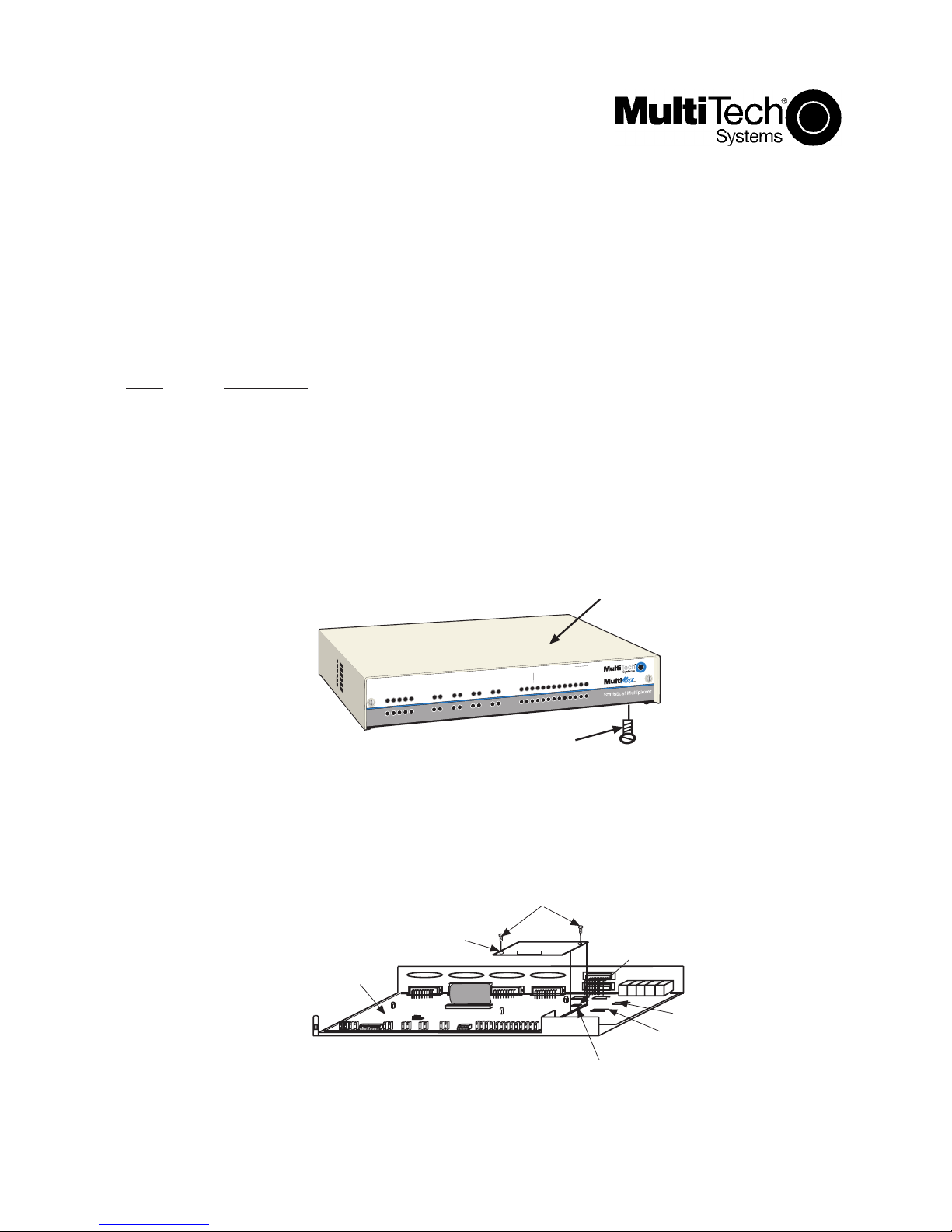
2 Turn the MultiMux power switch to OFF and unplug the MultiMux pow er cord from the wall outlet.
3 Turn the MultiMux upsidedown and remove the f our scre ws securing the cover to the base.
4 Slide the cover off the base.
Cover
Mounting
Screw
(x4)
MMH900 Cover
5 Plug in the Internal 56K DSU to the connector on the motherboard and the back 6-pins on the side 10-
pin connector. Be careful to align the 6-pins of the DSU with the pins on the 10-pin connector that
are the farthest from the modem 96-pin connector.
Modem Mounting
Screws
56K Internal
Motherboard
1 2 3 4 5 6 7 8
DSU
OTHER RKWL14.4
1 2 3 4
Base
Modem 10-pin
Connector
V.35 V.24
V29/V33
2834
Modem 96-pin
Connector
V.29/V.33
Shunt
2834
Shunt
1
Page 2
6 Secure the DSU to the base using the two plastic mounting screws provided in the upgrade kit. One of
the screws goes into the connector and the other one into the standoff on the motherboard.
7 Set switch position 2 of the 8-position DIP-switch to the OPEN (UP) position.
8 Slide the cover onto the base and replace the f our cover screws.
9 Attach the internal DSU serial tag to the bottom of the MultiMux cabinet next to the existing serial tag(s).
10 Connect the RJ48 cable provided in the upgrade kit to the COMPOSITE LINK INTERNAL DIGITAL DSU
connector on the backpanel of the MultiMux.
11 Connect the other end of the RJ48 cable into a telephone wall jac k and plug in the power cord.
12 Refer to Chapter 5 of your MultiMux Owner's Manual to configure y our internal DSU .
MMV1600/3200 Series DSU Upgrade Procedure
Step Procedure
1 Check the contents of your upgrade kit to ensure that it contains the parts listed below:
a) Screwdriver
b) Mounting screws (2)
c) MMH1656K DSU
d) Serial tag label
2 Turn the MultiMux power switch to OFF and unplug the MultiMux pow er cord from the wall outlet.
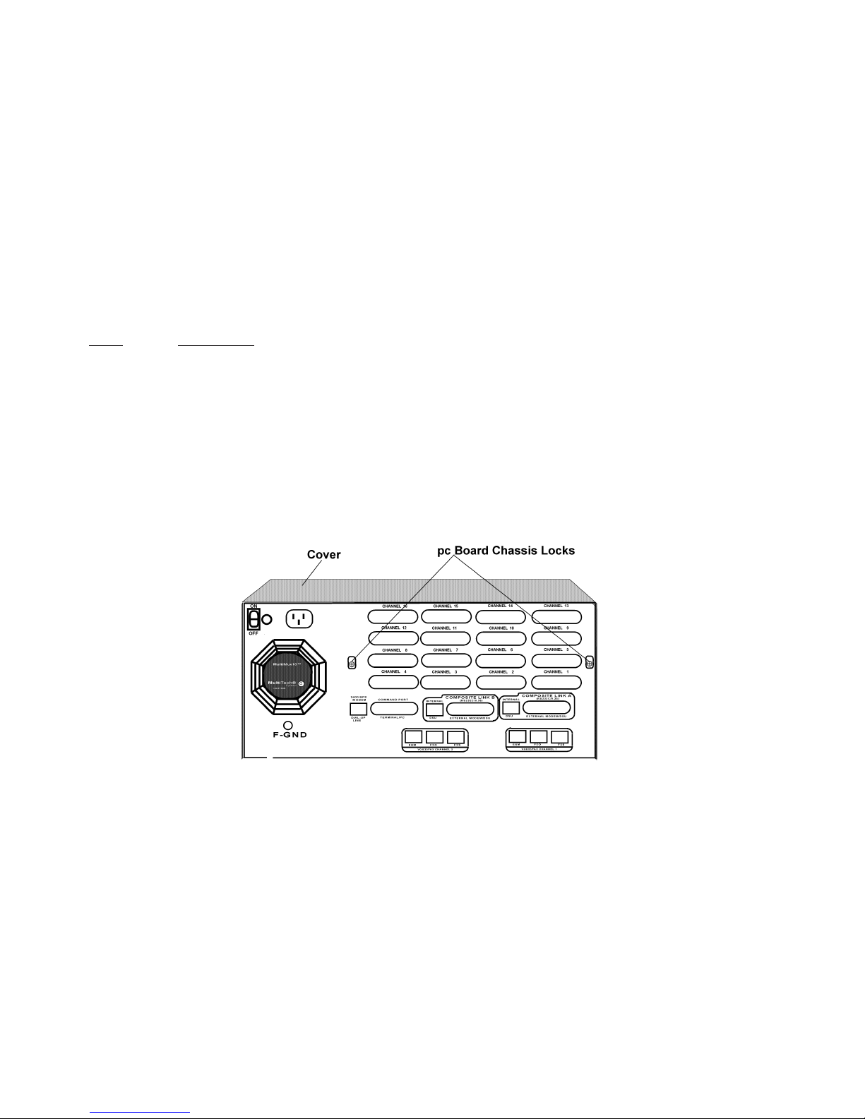
3 Loosen the four quarter-turn-fasteners on the front panel and remove the front panel.
4 Loosen the two pc board chassis lock screws on the back panel.
PC Board Chassis Lock Screws
5 Pry up on the two pc board chassis lock screws to unlock the pc boards in the chassis. Temporarily
retighten these screws while in the up position.
6 Disconnect the pc board power cable from the pow er supply.
7 Partially pull out all the pc boards in the chassis just past the inside edge of the data and address ribbon
cable connectors. It may require a slight forward tug on the voice/fax board (if installed) to free it from its
board edge connector while pulling the other boards forward.
8 Disconnect the control ribbon cable from the Aggregate board.
9 Disconnect the data and address ribbon cable connector from the Aggregate board.
2
Page 3

10 If the Voice/Fax board is in the chassis, remove the ribbon cab le betw een the Aggregate board and the
V oice/F ax board.
PC Board Removal
11 Remove the Aggregate board from the chassis .
12 Plug the DSU into either link A or link B on the Aggregate board being careful to align the 4-pin
connector with the receptacle on the mother board. The MultiMux will work with a DSU in either link A
and/or link B. If necessary, disconnect old DSUs/modems from the MultiMux.
Aggregate Board
13. Secure the DSU to the Aggregate board using the two plastic screws provided in the upg rade kit. One of
the screws goes into the connector on the other into the Aggregate board.
14 Slide the Aggregate board part way into the chassis.
15 If the Voice/Fax board is in the chassis, connect the short ribbon cable between the Aggregate board
and the Voice/Fax board. This ribbon cable goes on the front left side of the Aggregate board and is the
only connector on the Voice/Fax board.
16 Reconnect the control ribbon cable on the right side between the Aggregate board and the Channel
board(s).
WARNING: Make sure the ribbon cables are not crimped and are tight or the entire
MultiMux will be damaged when power is applied.
17 Reconnect the data and address ribbon cable on the left side between the Aggregate board and
Channel Board(s).
18 Slide all the boards fully into the chassis. The Voice/Fax board (if installed) will require an extra push to
seat it in its board edge connector.
3
Page 4

19 Ensure that the boards are seated into the back panel.
20 Ensure that the pc board chassis locks will seat into the boards. Then loosen, pry down and retighten
the screws.
WARNING: Ensure that the power cable connector pins align with the connector on
the power supply board and that the power cable connector has the
locking notch facing upward. If the cable is misaligned in any way severe
damage may occur to the unit.
21 Connect the pc board power cable to the pow er supply being careful that the pins are aligned properly.
22 Place the MultiMux on its side and place the internal DSU serial tag to the bottom of the MultiMux
cabinet next to the existing serial tag(s).
23 Place the MultiMux right-side up.
24 Set DIP-switch SW -5 on the Aggregate board f or the internal DSU . If an internal DSU was added to link
A, set DIP switch position 2 to the OPEN (UP) position. If an internal DSU was added to link B, set
switch position 3 to the OPEN (UP) position.
25 Connect the RJ48 cable provided in the upgrade kit to the COMPOSITE LINK A and/or B INTERNAL
DSU connector on the backpanel of the MultiMux.
26 Connect the other end of the RJ48 cable into a telephone wall jack.
27 Replace the front panel securing it to the chassis with the four quarter-turn fasterners.
28 Plug the power cord into the power receptacle on the bac k panel of the MultiMux and A C w all outlet.
29 Place the Pow er Switch in the ON position.
30 Refer to Chapter 5 of your MultiMux Owner's Manual to configure y our internal DSU .
4
 Loading...