

Page 1

MMH900 Series Statistical
Multiplexer
User Guide
Page 2

User Guide
S000315A Revision A
MultiMux (#MMH904Ca) (#MMH908Ca)
This publication may not be reproduced, in whole or in part, without prior
expressed written permission from Multi-Tech Systems, Inc. All rights
reserved.
Copyright © 2003, by Multi-Tech Systems, Inc.
Multi-Tech Systems, Inc. makes no representations or warranties with
respect to the contents hereof and specifically disclaims any implied
warranties of merchantability or fitness for any particular purpose.
Furthermore, Multi-Tech Systems, Inc. reserves the right to revise this
publication and to make changes from time to time in the content hereof
without obligation of Multi-Tech Systems, Inc. to notify any person or
organization of such revisions or changes.
Record of Revisions
Revision Date Description
A 11/01/03 Initial release of MultiMux MMH904/908C for
publication on CD.
TRADEMARK
Trademark of Multi-Tech Systems, Inc. are as follows: MultiMux,
MultiModem and the Multi-Tech logo.
Multi-Tech Systems, Inc.
2205 Woodale Drive
Mounds View, Minnesota 55112
(763) 785-3500 or (800) 328-9717
Fax (763) 785-9874
Tech Support (800) 972-2439
Internet Address: http://www.multitech.com
Page 3

Contents
Chapter 1 - Introduction & Description ................................ 8
1.1 Introduction.................................................................................... 9
1.2 About This Manual......................................................................... 9
1.3 Background ................................................................................... 11
1.3.1 Description of Statistical Multiplexing ................................... 12
1.3.1.1 Statistical Multiplexing .......................................................... 12
1.4 Product Description ....................................................................... 14
1.5 System Features ........................................................................... 17
1.5.1 Response Time Control........................................................ 17
1.5.2 Dynamic Buffering................................................................ 17
1.5.3 Flow Control......................................................................... 18
1.5.4 Diagnostics .......................................................................... 18
1.5.5 Downline Parameter Loading ............................................... 18
1.5.6 Operational Statistics and Auto-Reporting............................ 19
1.5.7 Parameter Memory .............................................................. 19
1.5.8 Channel Flexibility ................................................................ 19
1.5.9 Command Modem................................................................ 19
1.5.10 Composite Link .................................................................... 20
1.6 FCC Regulations for Telephone Line Interconnection ................... 21
1.7 DOC Terminal Equipment .............................................................. 23
1.8 Specifications ................................................................................ 24
1.8.1 Channels .............................................................................. 24
1.8.2 System Control..................................................................... 24
1.8.3 Composite LInk .................................................................... 25
1.8.4 33,600 bps Link Modem ....................................................... 25
1.8.5 56,000 bps DSU.................................................................. 25
1.8.6 ISDN T erminal Adapter......................................................... 26
1.8.7 Command Modem................................................................ 26
1.8.8 Electrical/Physical ................................................................ 26
Chapter 2 - Configuration ..................................................... 27
2.1 Introduction.................................................................................... 28
2.2 Configuration 1 .............................................................................. 29
2.3 Configuration 2 .............................................................................. 31
2.4 Configuration 3 .............................................................................. 32
Page 4

Chapter 3 - Front & Rear Panel Descriptions..................... 34
3.1 Introduction.................................................................................... 35
3.2 Front Panel .................................................................................... 35
3.3 LED Indicators .............................................................................. 36
3.4 Back Panel .................................................................................... 40
3.4.1 ON/OFF Switch.................................................................... 40
3.4.2 Power Connector ................................................................. 40
3.4.3 COMMAND MODEM DIAL-UP Connector .......................... 40
3.4.4 COMMAND PORT Connector.............................................. 40
3.4.5 COMPOSITE LINK INTERNAL MODEM DIAL-UP Connector40
3.4.6 COMPOSITE LINK INTERNAL MODEM LEASED Connector41
3.4.7 COMPOSITE LINK INTERNAL DIGITAL DSU Connector.... 41
3.4.8 COMPOSITE LINK EXTERNAL RS232C/V.35 Connector ... 41
3.4.9 CHANNEL 1 - CHANNEL 8 Connectors............................... 41
3.5 Switches/Jumper/Shunt................................................................. 42
3.5.1 8-Position DIP Switch........................................................... 42
3.5.2 4-Position DIP Switch........................................................... 43
3.5.3 144RKWL/OtherJumper ....................................................... 44
3.5.4 V.24/V .35 Shunt.................................................................... 44
3.5.5 V.29/V .33 Shunt and 2834 Shunt.......................................... 44
Chapter 4- Installation........................................................... 45
4.1 Introduction.................................................................................... 46
4.2 Safety Warnings ............................................................................ 46
4.3 Unpacking...................................................................................... 46
4.4 Installation ..................................................................................... 47
Chapter 5 - Commands ......................................................... 52
5.1 Introduction.................................................................................... 53
5.2 Command Description ................................................................... 58
5.2.1 General Commands ............................................................. 58
5.2.2 Channel Parameter Commands ........................................... 65
5.2.3 Composite Link Commands ................................................. 74
5.2.4 Composite Link Format Commands ..................................... 78
5.2.5 Internal 9600/14.4K Composite Link Modem Commands..... 81
5.2.6 Internal MMH2834 Modem Configuration Commands.......... 84
Page 5

5.2.7 Internal Composite Link DSU Commands ............................ 86
5.2.8 Test Commands ................................................................... 87
5.2.9 Command Modem commands ............................................. 89
Chapter 6- Operating Procedures ....................................... 90
6.1 Introduction.................................................................................... 91
6.2 MultiMux Operating Procedures .................................................... 91
6.3 Command Modem Operating Procedures ..................................... 95
Chapter 7 - Troubleshooting ................................................ 97
7.1 Introduction.................................................................................... 98
7.2 Importance of Composite Statistics ............................................... 98
7.3 Test Cables.................................................................................... 99
7.4 Troubleshooting Guide .................................................................. 101
7.5 Channel Device Testing................................................................. 107
7.6 Local Modem and Communications Line Testing .......................... 108
7.7 MultiMux Functional Testing Procedures ....................................... 110
Chapter 8- Service, Warranty, & Technical Support ......... 112
8.1 Introduction.................................................................................... 113
8.2 Warranty ........................................................................................ 113
8.3 Repair Procedures for U.S. and Canadian Customers.................. 114
8.4 Repair Procedures for International Customers (Outside U.S.A. and
Canada) ............................................................................................ 115
8.5 Repair Procedures for International Distributors............................ 116
8.6 Online Warranty Registration......................................................... 116
Appendices.......................................................................... 117
Appendix A .............................................................................................. 1 18
Ascii Character Code/Hex/Decimal Conversion Chart ...................... 118
Appendix B
RS232C Interface Specification ........................................................ 119
Page 6

Appendix C.............................................................................................. 121
Cabling Diagrams.............................................................................. 121
Appendix D.............................................................................................. 125
Command Modem Commands ......................................................... 125
Appendix E Command Modem S-Register Function.............................. 138
Appendix F .............................................................................................. 143
Flow Control Background.................................................................. 143
Appendix G ............................................................................................. 146
MMH2834 S-Registers...................................................................... 146
Appendix H.............................................................................................. 149
Dial Back-up...................................................................................... 149
Appendix I ............................................................................................... 150
T esting Your MMH2834 ..................................................................... 150
I.1 Introduction ................................................................................ 150
I.2 Local Analog Loopback Test/V.54 Loop 3.................................. 151
I.3 Digital Loopback Test/V.54 Loop 2 (Loc/Man)...................... 152
I.4 Digital Loopback Test/V.54 Loop (Rem/Auto) ............................ 154
I.5 Synchronous Mode Testing ................................................. 156
I.6 Local Analog Loopback Test (Sync Mode)........................... 157
I.7 Digital Loopback Test (Loc/Man) Sync Mode ...................... 158
I.8 Digital Loopback Test (Rem/Auto)(Sync Mode)................... 159
Appendix J - Internal MMH2834 Composite Link Modem Commands.... 160
J.1.1 Dialing Action Commands ........................................................ 163
J.1.2 Dial Modifier Commands ...................................................... 165
J.1.3 Phone Number Memory Commands .................................... 168
J.1.4 Configuration and Default Storage Commands .................... 170
J.1.5 Command Response (Result Code) Commands..................... 172
J.1.6 Phone Line Conditioning Commands ...................................... 176
J.1.7 RS232C Interface Control Commands ..................................... 177
J.1.8 Error Correction Commands ................................................ 178
J.1.9
Compression and Maximum Block Size Commands ............ 180
J.1.10 Speed Conversion Commands............................................. 181
J.1.11
Immediate Action Commands............................................... 183
Glossary............................................................................... 185
Index..................................................................................... 195
Page 7

Chapter 1 - Introduction &
Description
Page 8
Chapter 1 - Introduction & Description
1.1 Introduction
Congratulations! Your new MultiMux MMH900 series is one of the finest
statistical multiplexers on the market today. The MultiMux is completely
software driven and is controlled by you through its command port. This
gives you great flexibility and ease of operation. This Owner’s Manual
will help you to install and use your MultiMux, and also provide you with
a valuable information resource in the future.
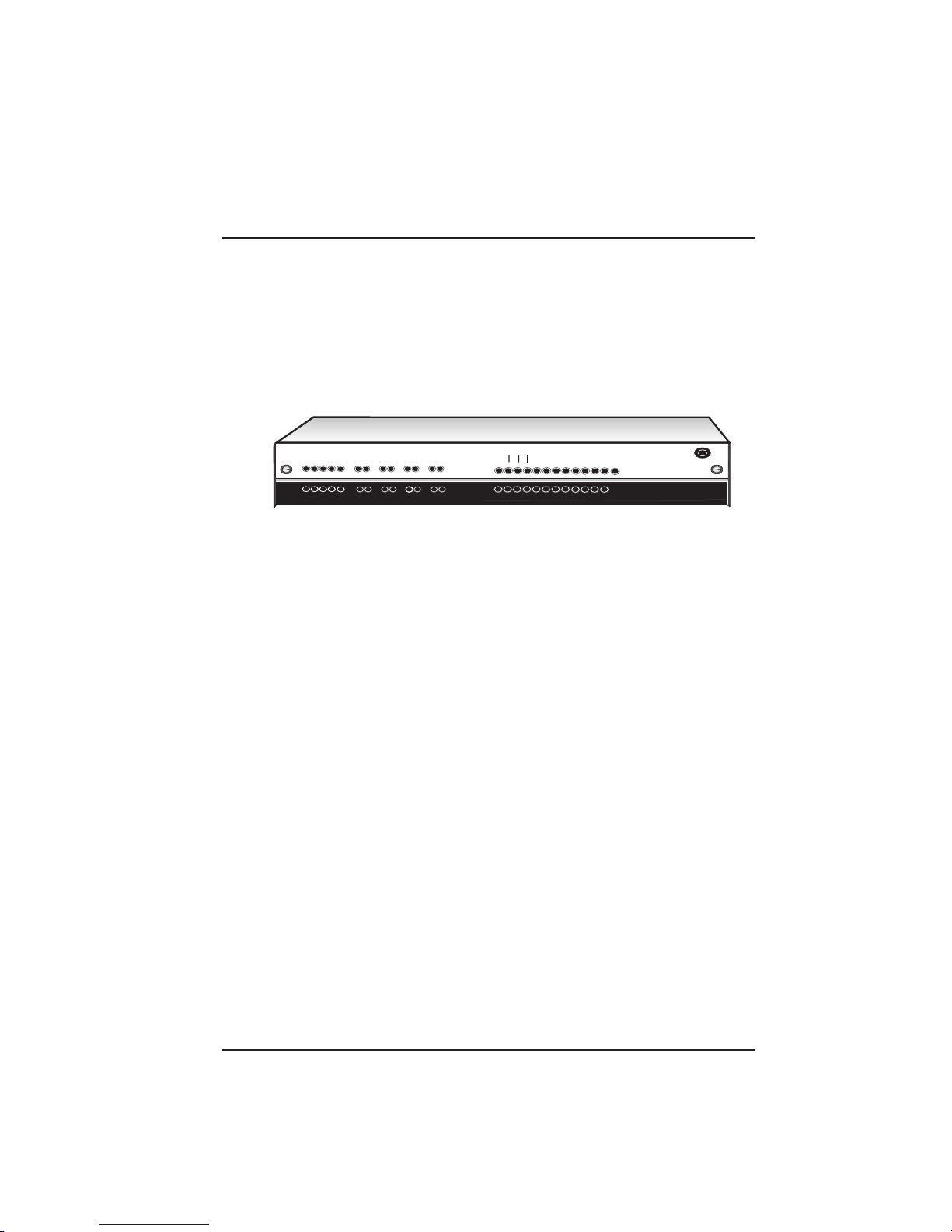
A
Command Modem
RCV
CD
External Composite Link
CD
RCV
R
BUFFER
E
FULLNESS
T
LEVEL
R
A
N
S
XMTRCV XMTRCV XMTRCV
RCV
XMTRCV
Channel Eight
RCV XMTXMTRCV
Channel Six Channel Seven
Channel Five
XMT
OH
RCV
XMT
DTR
Channel one
V.35
Channel Two Channel Three Channel Four
XMT
CTS
XMT
M
IT
2
1
3
Internal Composite Link
ISDN
MMH2834 CD RCV XMT CTS 28.8 24.0 19.2 14.4 OH TR EC DBUP
DSU CD RCV XMT CTS 56 19.2 RTS NS OOS TM
V29/V33 CD RCV XMT CTS
INTERNAL LINK DEVICE
F
R
T
L
S
L
E
E
I
O
C
T
R
L
R
C
V
(Modems)
M
Y
S
N
O
T
N
K
T
C
E
A
L
M
L
D
D
A
O
I
W
S
R
D
N
N
M
U
E
K
MultiTech
M
V
M
2
H
9
I
2
/
S
V
8
3
D
3
3
N
4
Systems
MultiMux
Statistical Multiplexer
Figure 1-1. MultiMux MMH900 Series
1.2 About This Manual
eThis manual is comprised of eight chapters. There are also several
appendices at the end of the manual, most of which is a condensed
version of the information contained in the chapters. These appendices
can be used as a quick reference. The information contained in each
chapter is as follows:
Chapter 1 - Introduction
This chapter is an introduction to the world of multiplexing. Since you
have already acquired the MultiMux, you may have an extensive
background in multiplexing. In which case, this introduction will provide a
good review.
Chapter 2 - Configuration
This chapter defines the configurations of the MMH900 series and
provides some typical examples of how the MultiMux is configured. The
MMH900 series is available in two models; the four and eight channel
units with an internal command modem, various composite link modems
supporting synchronous or asynchronous communications. The typical
examples explain how the MultiMux can be used in various
environments.
8
Page 9

Chapter 1 - Introduction & Description
Chapter 3 - Front and Rear Panel Descriptions
Chapter 3 describes the front panel indicators, the switches and jumpers
within the cabinet and the rear panel connections. The front panel
indicators are described in the various groups depending on the
configuration of the MultiMux. Indicator groups are active depending on
how the MultiMux is used. The front panel is the same for all models
and contains some indicators for future enhancements. The back panel
provides all the cable connections for the early released models with the
addition of cable connections for future releases.
Chapter 4 - Installation
Chapter 4 provides the procedures for unpacking, installing and cabling
your MultiMux. After your MultiMux is cabled, an initial power on
procedure is provided for you to display and modify the channel and link
parameters to fit your configuration.
Chapter 5 - Commands
The MultiMux is software-driven and controlled through its command port
and the supervisory console. This chapter describes the AT commands
and the impact each has on your system’s operation.
Chapter 6 - Operating Procedures
Chapter 6 provides the operational information for your MultiMux. The
MultiMux operating procedures address the channel and composite link
parameters. The command modem operating procedures address the
command modem access, dialing, and remote access procedures.
Chapter 7 - Troubleshooting Procedures
This chapter is a guide to troubleshooting your MultiMux. It contains a
listing of error conditions, probable causes and suggested fixes or steps
designed to isolate the failing unit in your communications network.
Chapter 8- Service, Warranty and Tech Support
Chapter 8 provides instructions on getting service for the MultiMux at the
factory , a statement of the limited warranty, information about our user
bulletin board service, and space for recording information about your
multiplexer prior to calling Multi-Tech's Technical Support.
9
Page 10
Chapter 1 - Introduction & Description
1.3 Background
Any data communications environment that has more than one
asynchronous line going between common locations can probably
benefit by installing a pair of statistical multiplexers (stat muxes). A stat
mux performs the function of combining several asynchronous data
communication channels into one composite signal that can be
transmitted between two locations more inexpensively than the cost of
the individual lines.
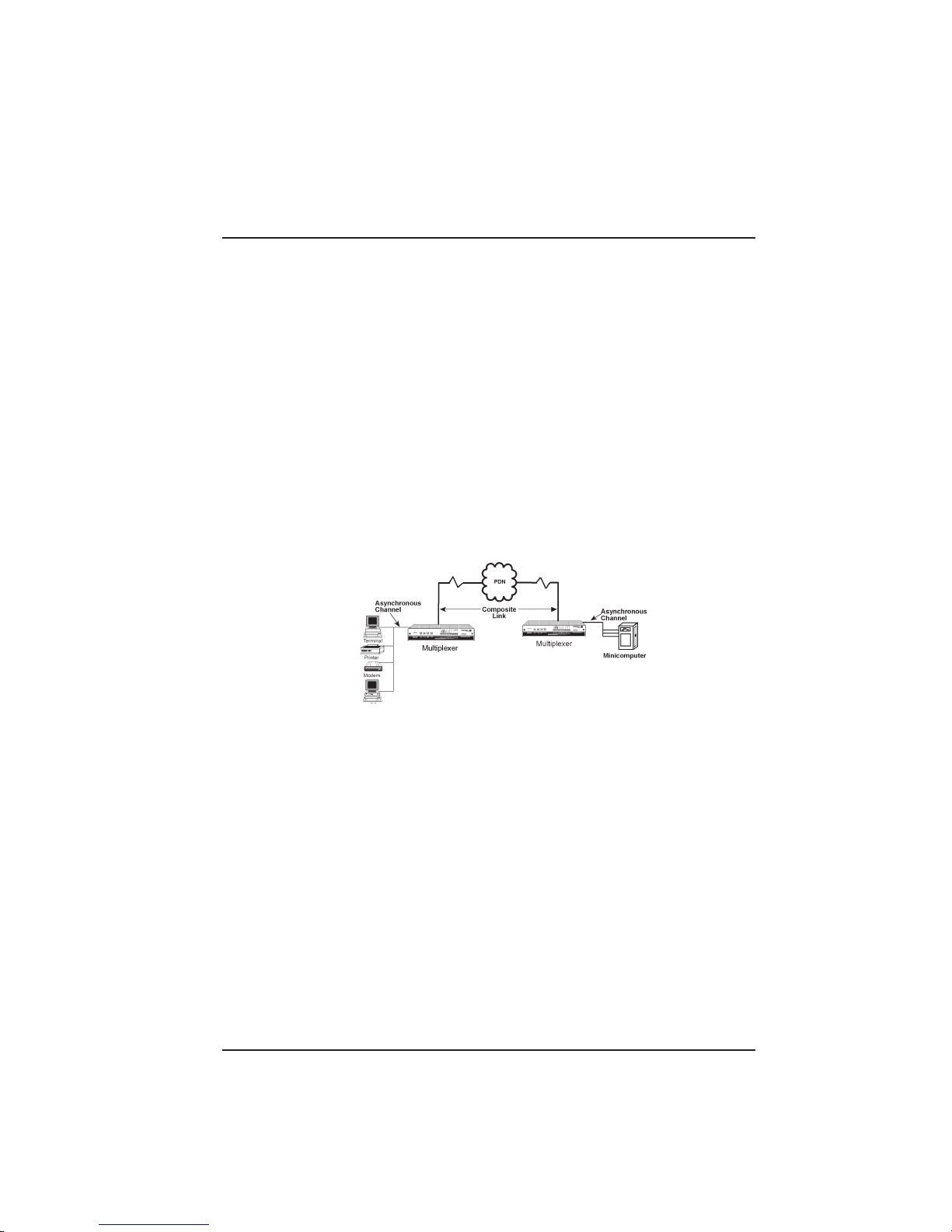
Figure 1-2 shows a simple communications network. Individual users
connect to asynchronous channels and the composite (or aggregate)
communications line between the two locations is the "link". Link
protocol is the communications discipline used between the two
multiplexers and typically operates at a speed higher than the individual
asynchronous units connected to each multiplexer.
Figure 1-2. Simple Communications Network
One reason that a stat mux works is that typically an asynchronous
terminal device is not used to its capacity . Studies show that as little as
10 to 15% utilization of such lines is a common occurrence. These
percentages indicate that the most efficient combination of lines in a
muxed asynchronous environment is between four and eight lines.
Although the primary reason for installing a mux is to save on
communications costs, two other benefits are also present. One is the
inherent error correction existing in muxed data and the other is data
security . Since a mux functions by taking individual asynchronous data
and transmitting it as data packets, there is an error detection and
retransmission scheme built in. Error correction is so vital in many
transmission types, such as graphic data and program transmission, that
many muxes are used mainly for their error correction capabilities.
The other benefit is data security which is achieved by the fact that the
individual data streams are encrypted into a single communication line
10
Page 11

Chapter 1 - Introduction & Description
on one end of the link and then broken up into individual components on
the other end. Someone wishing to "tap" into a muxed signal must not
only have the link protocol which is typically a proprietary version of High
Level Data Link Control (HDLC), but must also know the individual
channel assignment schemes and data formats.
1.3.1 Description of Statistical Multiplexing
A statistical multiplexer (also known as a stat mux) is a device that
allows several other devices (usually computer terminals or PCs) to
communicate over a single transmission line. Sometimes called
concentrators, they take data from different devices and combine it into a
single stream that can be transmitted, via a modem, to an identical
multiplexer at another location, where the stream is then separated back
into its original form. Physically , a mux looks like a box with a bunch of
serial ports and some LEDs. The most typical task of the MultiMux is to
connect a group of PCs or terminals at one site to a mini or mainframe
computer at another site via a single set of modems rather than using
individual modems for each PC or terminal.
1.3.1.1 Statistical Multiplexing
Statistical multiplexing is sometimes referred to as statistical timedivision multiplexing (STDM). The use of the voice-grade phone line (or
any other communications link) is based not on peak data rates, but on
effective (or average) data rates.
During the peaks, when the sum of the data rates of the channels being
served exceeds the data rate of the composite link, a statistical
multiplexer saves the excess data in buffers (in effect, allowing individual
channel buffers to expand). The buffers are emptied as soon as the
activity falls off. The proper allocation of buffer space, plus the
implementation of “flow control” and “pacing” techniques to
accommodate unusually high peaks, allows the use of composite link
speeds that are less than the sum of the individual channel speeds.
In effect, a statistical multiplexer services only active channels. However ,
the efficiency thus realized is not the only benefit of the technique.
Because composite link activity need not be synchronized with the
activity on the individual channels, there is considerable flexibility in the
choice of the composite channel protocol and speed. The use of a
synchronous protocol like HDLC provides for error detection and
retransmission over the composite link. Thus, asynchronous terminals,
which have no inherent error-recovery capability , can enjoy end-to-end
data integrity.
11
Page 12

Chapter 1 - Introduction & Description
1.3.1.2 Communications
The basic functions of multiplexing are to make communications more
efficient, to provide a means of improving accuracy of asynchronous
communications by using synchronous techniques, and to improve data
security by encrypting several data streams into one coded link.
The channel devices can be any asynchronous RS232 compatible units,
from “dumb terminals” to personal computers running asynchronous
communications software. The connection between the channel devices
and the MultiMux is made through an RS232 interface cable.
Asynchronous modems (long haul or short haul), asynchronous modem
emulators and asynchronous line drivers (DCE devices) can be used in
this connection (up to 38.4K bps) to extend the distance between the
channel devices and the MultiMux.
The connection between the two MultiMuxes is the composite link, and
can be up to 128K bps. Using an internal modem, ISDN terminal
adapter, DSU, or external device, the MultiMux can be connected to
different types of communications links, such as a dial-up line, leased
line, Basic Rate Interface (BRI) ISDN service, or a DDS network. If an
external link device is used the MultiMux can communicate with it using
either the RS232 or V.35 standard.
12
Page 13
Chapter 1 - Introduction & Description
Workstation PC
1.4 Product Description
There are two basic models of MultiMux MMH900 series available: a
four channel and eight channel units with internal command modem,
optional composite link modems and a command port. The four channel
MultiMux MMH904 connects four async devices to asynchronous
channels that transfer data at a channel speed of up to 38.4K bits per
second (bps). The eight channel MultiMux MMH908 connects eight
async devices. The composite link of the MultiMux MMH900 series can
be configured for various dial-up and lease line modems, a Digital
Service Unit (DSU) for digital communications over a Digital Data
Service (DDS) or dedicated network, or an ISDN terminal adapter for
Basic Rate Interface Service. The command port allows you to
configure the MultiMux MMH900 series for your channel configuration,
internal hardware and composite link configuration.
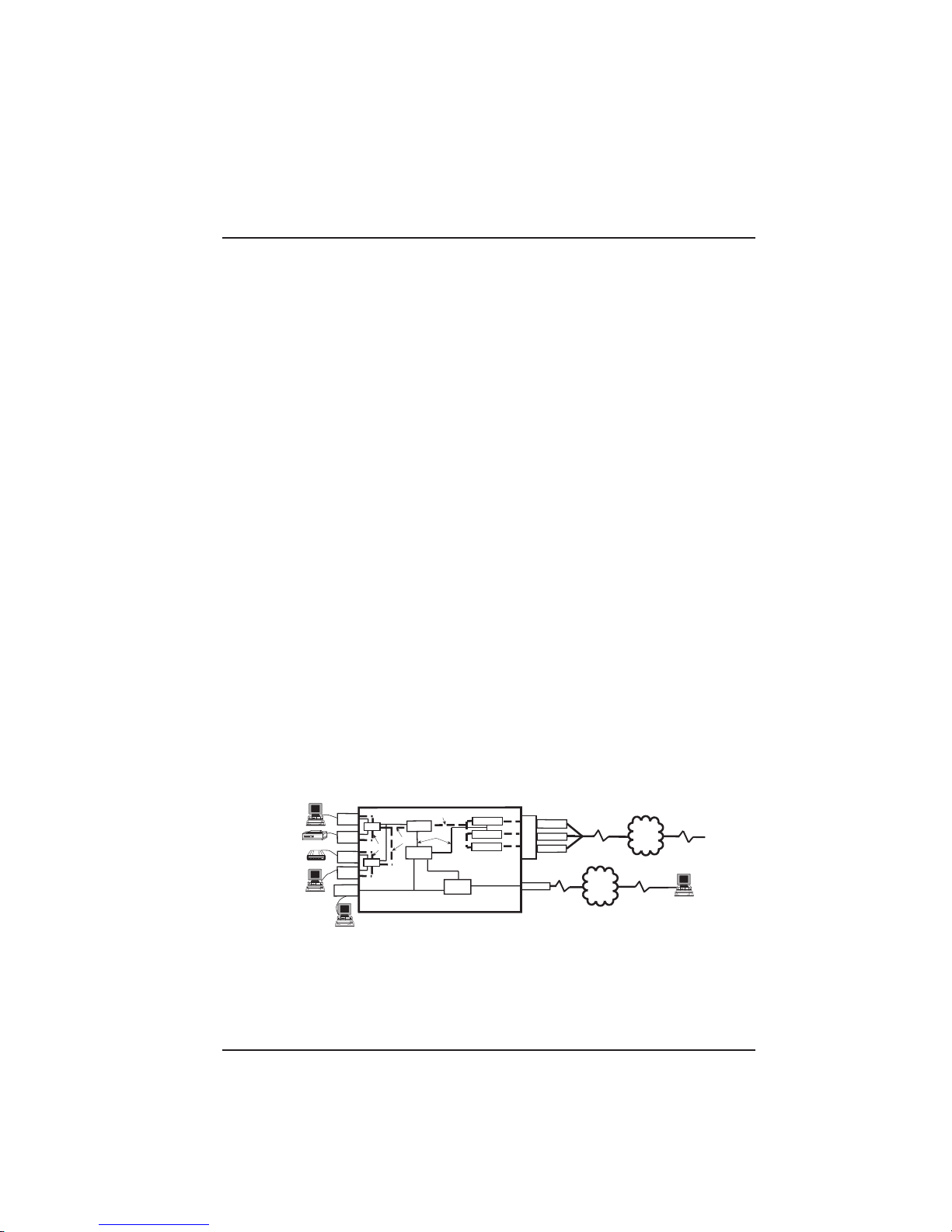
A simplified block diagram of a MultiMux network is shown in Figure 1-3
to give you a pictorial view of a complete network. The MultiMux
represented in the figure is a MultiMux MMH904 connected to four async
devices on CHANNEL 1 through CHANNEL 4. The workstation
connected to the COMMAND PORT is the supervisory console in which
you can communicate with the command processor or command
modem. If a remote connection is needed to the command modem, a
separate DIAL-UP connection is provided. The composite link can be
configured for an internal 28.8K bps dial-up/leased line modem, internal
DSU for digital communications over a digital data service (DDS)
network or an ISDN terminal adapter for Basic Rate Interface Service. It
can also be configured for external synchronous link device with either
V.24 or V .35 interface.
Figure 1-3. MultiMux MMH900 Series Block Diagram
To setup a MultiMux MMH900 series, the async devices have to be
connected to the channels, the composite link connected to the public
data network (PDN) and the MultiMux has to be configured for the
Channel
Channel
Channel
Channel
Command
Port
4
3
2
1
Data
I/O
Processor
AT Commands
Channel
Data
Channel
Data
Command
Processor
I/O
ATCommands
MultiMux 900 Series
Composite
Link Data
AT Commands
Command
Modem
Dial-Up Modem
Lease Modem
DSU
AT Commands
C
o
m L
p i
o n
s k
i
t
e
Dial-up
Dial-Up Modem
Lease Modem
Digital
Dial-up
Composite
Link
Line
PDN
Dial-up
Composite
Link
PDN
Line
Workstation PC
13
Page 14

Chapter 1 - Introduction & Description
channel devices and the composite link. The async devices are
connected to CHANNEL 1 through CHANNEL 4 connectors on the back
panel of the MultiMux MMH904 with an RS232 cable. The MultiMux
MMH908 has four additional channel connectors for connecting up to
eight devices.
A number of internal and external composite link devices can be used to
connect the MultiMux to the PDN. The MMH900 series has an internal
28,800 bps composite link modem or an internal 56,000 bps DSU. The
modem is connected to the PDN through the INTERNAL COMPOSITE
LINK LEASED MODEM connector on the back panel of the MultiMux.
The internal DSU is connected to a DDS or dedicated network through
the COMPOSITE LINK DIGIT AL DSU connector on the back panel.
The supervisory console is connected to the MultiMux through the
COMMAND PORT connector on the back panel. The supervisory
console connection is also an RS232 connection. This completes a
typical hardware setup for a MultiMux. Now the MultiMux has to be
configured to talk to the channel devices and communicate over the
composite link.
Configuration of a MultiMux is accomplished through a combination of
setting DIP switches behind the front panel and software commands
entered through the supervisory console. The DIP switches determine
whether the MultiMux is a four or eight channel multiplexer, whether the
composite link device is an internal modem or DSU or an external
device, whether or not the command modem will accept remote access,
etc. The DIP switches control the hardware setup and the operating
setup is controlled through software commands. The software
commands are entered at a terminal connected to the COMMAND
PORT which are transferred to either the command processor or
command modem in the MultiMux. The software commands are AT
commands that configure the channel devices to communicate with the
MultiMux and configure the composite link device to communicate with
the PDN. To configure a channel device, the correct channel speed has
to be established, number of data and stop bits in a word determined,
the type of flow control and whether or not it is used and whether or not
pacing is active. These are just some of the AT commands that are used
to configure and display the status of the channel devices.
When the MultiMux MMH900 series is powered up, the command
processor transfers the stored configuration of the channel devices to
the data processor. The data processor takes the configuration
information and configures each channel for its particular conditions.
14
Page 15

Chapter 1 - Introduction & Description
The composite link has to be configured for its parameters before data
can be transferred.
The composite link parameters are determined by more than just AT
commands transferred to the command processor. The composite link
parameters are determined by what type of device is used, whether it is
internal or external, speed, what type of remote multiplexer we are
communicating with and a number of line conditioning parameters. The
type of device used as the composite link device is determined by
whether the device is internal or external which is established by a DIP
switch setting and by the type of device installed in the MultiMux or
connected to the EXTERNAL COMPOSITE LINK RS232C/V.35
connector on the back panel. If an internal composite link MMH2834
modem is installed, the DIP switch would be set for an internal
composite link device. The type of MultiMux at the other end of the
composite link is determined by the setting of a four position DIP switch
within the MultiMux. The MultiMux MMH900 series is now ready to
transfer data from its async devices through an internal composite link
modem.
15
Page 16

Chapter 1 - Introduction & Description
1.5 System Features
1.5.1 Response Time Control
Response time control is the technique used by a mux to make sure that
no user experiences undue delays in performance due to a specific
channel using too much link time. This can occur if one of the channels
is performing a high volume batch function, such as a print dump or
program transfer.
There are a variety of priority control (response time) schemes in use by
different mux vendors. Some vendors use a switch selection approach
where each channel can be given a high, medium or low setting with the
low used for those channels requiring higher volume batch transfers.
There are also software-sensing response time techniques where the
microprocessor actually monitors channel activity , and when a high
volume is sensed, that channel is given a lower priority so it will not
crowd out the others.
The MultiMux response time control method is one where data is
transferred from each channel on a timed basis while limiting the amount
sent with each transmission.
This insures that interactive users will not experience undue delays but,
on the other hand, batch activity can still be accommodated. This,
combined with a Response Time command and the ability to shut of f
channels not being used, gives the MultiMux a very efficient priority
control system.
1.5.2 Dynamic Buffering
A basic requirement of all muxes is some sort of buf fering capability to
temporarily hold channel data while it is being assembled into a block. In
the early days, a mux was sometimes judged by the size of its buffers.
Large buffers are unnecessary in newer designs that include
sophisticated dynamic buffer allocation techniques where the amount of
buffer per channel is assigned on an as-needed basis.
In the MultiMux, each channel is assigned 1K of buffer, but in the case
where more buffer is needed, the MultiMux will start assigning additional
buffers from the channels not requiring it. In this way a single channel
can have up to 8K of buffer if required. When dynamic buffering is
combined with efficient flow control and the automatic transmission of
data from each channel at set intervals, as in the MultiMux, very smooth
operation for each user is the result.
16
Page 17

Chapter 1 - Introduction & Description
1.5.3 Flow Control
Flow control regulates the volume of data entering the buffers. When a
particular channel buffer is almost full, a flow control command is issued
which stops further activity until the buffer is emptied. The most common
flow control methods currently used are Xon/Xoff, RS232C signal control
(using DTR or CTS) and ENQ/ACK. The MultiMux supports all three.
MUX INITIATED
FLOW CONTROL
Channel
Device
Flow control stops the
input of data to the mux
DATA
Mux
CHANNEL DEVICE
INITIATED PACING
DATA
Mux
Pacing stops the output
of data from the mux
Channel
Device
1.5.4 Diagnostics
Diagnostics in a multiplexer network are of considerable importance.
When a multiplexer fails there is not just one operator down, but many .
That is why the MultiMux is equipped with several diagnostic modes that
will test every aspect of the network. The diagnostics include easy-toexecute tests for each channel, the composite link and for various
components of the MultiMux unit itself. There are nine different test
modes to ensure error free operation. They include Analog Loop, Digital
Loop, Remote Analog Loop, Switch and LED tests, Non-Volatile Memory
test, three other tests and a “Watchdog Timer” reset test.
1.5.5 Downline Parameter Loading
Operational parameters for both local and remote MultiMux units can be
set from one location. The MMH900 series can downline load
parameters to each other, but they cannot send parameters to the
MM16xx/MM32xx and MMH16/MMH32 units. When power is first applied
(or a Reset command is executed) to the local or remote MultiMux,
operational parameters are automatically sent over the composite link to
the remote MultiMux. For this function to work, the 8-position DIP switch
SW1 on the local (sending) MultiMux must be set to the OPEN position
and on the remote (receiving) MultiMux the 8-position DIP switch SW1
must be set to the CLOSED position.
17
Page 18

Chapter 1 - Introduction & Description
1.5.6 Operational Statistics and AutoReporting
Operational statistics provides the activity report for the MultiMux
network, and Auto-Reporting provides a means to report on these
statistics through the supervisory console on a set periodic time cycle.
Statistics such as receive-block errors pinpoint modem or line problems,
and flow control time totals indicate channel devices being set at
excessive speeds. T wo simple commands are all that is necessary to
select statistical reporting and time cycle. If your command port is also
connected to a printer, the reports can provide an easy means of
generating data for better network management.
1.5.7 Parameter Memory
A nonvolatile memory for storing configurations and options means that
the MultiMux remains configured until you change it. Using this feature,
you can configure a MultiMux, turn it off, ship it and use it without having
to reconfigure it.
1.5.8 Channel Flexibility
The MultiMux permits a great deal of flexibility in configuring channel
parameters. You can mix up channel options, including speed, word
length, stop bits, parity , flow control, pacing methods, echoes and passthrough characters. Channel control commands let you change single
channels, all channels or selected channels with a single command. By
using the downline loading capability or the command modem, channels
can be configured at the other end of the network.
1.5.9 Command Modem
The MultiMux can connect to a dial-up phone network through an
integral 2400/1200/300 bps V .22bis-compatible modem called the
“command modem”. The command modem is an asynchronous modem
used for remote configuration of the mux. The command modem is not to
be confused with the “link modem”, which is either an internal or external
synchronous or external asynchronous device handling the data
transfers over the composite link between two muxes.
By using the command modem, you get the equivalent of a remote
Command Port console. Your MultiMux can be dialed into from a remote
location for remote testing and configuration. The command modem will
automatically answer incoming calls.
18
Page 19

Chapter 1 - Introduction & Description
1.5.10 Composite Link
The composite link of the MultiMux is capable of synchronous,
asynchronous and digital communications. The MultiMux can be
connected to several different types of communications links through
various modems and DSUs connected internally and externally .
Internally the MultiMux can be configured with synchronous lease line
modem at a link speed up to 28.8K bps or a Data Service Unit (DSU) at
link speeds up to 56K bps. Externally the MultiMux can be configured
with either a synchronous or asynchronous composite link modem or a
DSU for digital communications. The external modems must have error
correction and should have data compression for increased thru put and
only hardware flow control.
19
Page 20

Chapter 1 - Introduction & Description
1.6 FCC Regulations for Telephone Line
Interconnection
1. This equipment complies with Part 68 of the FCC rules. On the
outside surface of this equipment is a label that contains, among
other information, the FCC registration number and ringer
equivalence number (REN). If requested, this information must be
provided to the telephone company .
2. As indicated below the suitable jack (USOC connecting
arrangement) for this equipment is shown. If applicable, the facility
interface codes (FIC) and service order codes (SOC) are shown.
3. The ringer equivalence number (REN) is used to determine the
quality of devices which may be connected to the telephone line.
Excessive REN’s on the telephone line may result in the devices not
ringing in response to an incoming call. In most, but not all areas, the
sum of the REN’s should not exceed five (5.0). To be certain of the
number of devices that may be connected to the line, as determined
by the total REN’s, contact the telephone company to determine the
maximum REN for the calling area.
4. If this equipment causes harm to the telephone network, the
telephone company will notify you in advance. But if advance notice
isn’t practical, the telephone company will notify the customer as
soon as possible. Also, you will be advised of your right to file a
complaint with the FCC if you believe it is necessary .
5. The telephone company may make changes in its facilities,
equipment, operations, or procedures that could affect the operation
of the equipment. If this happens, the telephone company will
provide advance notice in order for you to make necessary
modifications in order to maintain uninterrupted service.
6. If trouble is experienced with this equipment (the model of which is
indicated below) please contact Multi-Tech Systems, Inc. at the
address shown below for details of how to have repairs made. If the
trouble is causing harm to the telephone network, the telephone
company may request you remove the equipment from the network
until the problem is resolved.
7. No repairs are to be made by you. Repairs are to be made only by
Multi-Tech Systems or its licensees. Unauthorized repairs void
registration and warranty .
20
Page 21

Chapter 1 - Introduction & Description
8. This equipment cannot be used on public coin service provided by
the telephone company. Connection to Party Line Service is subject
to state tariffs. (Contact the state public utility commission, public
service commission or corporation commission for information.)
9. If required, this equipment is hearing aid compatible.
Manufacturer: Multi-Tech Systems, Inc.
Model Number: #MMH904/MMH908
FCC Registration No.: AU7USA-73205-FA-E
AU7USA-18883-DE-N (DSU)
Ringer Equivalence: 0.8B (command modem)
Modular Jack (USOC): RJ11C or RJ1 1W (single line)
Service Center in USA: Multi-Tech Systems, Inc.
2205 Woodale Drive
Mounds View , MN. 55112 USA
(763) 786-3500 or (800) 328-9717
U.S. FAX (763) 785-9874
21
Page 22

Chapter 1 - Introduction & Description
1.7 DOC Terminal Equipment
Notice: The Canadian Department of Communications label identifies
certificated equipment. This certification means that the equipment
meets certain telecommunications network protective, operational and
safety requirements. The department does not guarantee the equipment
will operate to the user’s satisfaction.
Before installing this equipment, users should ensure that it is
permissible to be connected to the facilities of the local
telecommunications company . The equipment must also be installed
using an acceptable method of connection. In some cases, the
company’s inside wiring associated with a single line individual service
may be extended by means of a certified connector assembly (telephone
extension cord). The customer should be aware that compliance with the
above conditions may not prevent degradation of service in some
situations.
Repairs to certified equipment should be made by an authorized
Canadian facility designated by the Supplier. Any repairs or alterations
made by the user to this equipment; or equipment malfunctions, may
give the telecommunications company cause to request the user to
disconnect the equipment.
Users should insure for their own protection that the electrical ground
connections of the power utility , telephone lines and internal metallic
water pipe system, if present, are connected together. This precaution
may be particularly important in rural areas.
Caution: Users should not attempt to make such connections
themselves, but should contact the appropriate electric inspection
authority , or electrician, as appropriate.
The Load Number (LN) assigned to each terminal device denotes the
percentage of the total load to be connected to a telephone loop which is
used by the device, to prevent overloading. The termination on a loop
may consist of any combinations of devices subject only to the
requirement that the total of the Load Numbers of all the devices does
not exceed 100.
The load number for the Command Modem is 8.
22
Page 23

Chapter 1 - Introduction & Description
1.8 Specifications
1.8.1 Channels
Number of Channels Up to four (#MMH904), or up to eight
(#MMH908)
Maximum Speed 38,400 bps All Channels
Channel Speeds All standard speeds from 150 bps to 38.4K
bps
Data Format Asynchronous: 5, 6, 7, or 8 data bits, with
1,1.5, or 2 stop bits
Parity Odd, even, or none, fully transparent
Local Echo On or off selectable for each channel
Flow Control Xon/Xoff, CTS on/off, or HP ENQ/ACK
selectable for each channel
Pacing On or off selectable for each channel, DTR
on/off, or Xon/Xoff
Interface RS232C/CCITT V.24; 25-pin female D
connectors
1.8.2 System Control
Local Access Through MultiMux’s RS232C “Command
Port” Remote Access Through MultiMux’ s
internal dial-up CCITT V.22bis/V .22, Bell
212A/103 (2400/1200/300 bps) command
modem
Device Any asynchronous keyboard terminal, PC in
terminal mode (local access), or any
standard dial-up 2400/1200/300bps V .22bis/
V.22, 212A/103 modem (remote access)
Command Functions Menu-driven/help screen approach.
Commands to select channel speeds, flow
control methods, listing of parameters, help
screens, storing of configurations, downline
loading, status reporting, echo controls,
resets, pacing parity , stop bits, reponse time
priorities, test modes, modem
configurations, and other parameters.
23
Page 24

Chapter 1 - Introduction & Description
Diagnostics Memory test, Analog Loop, Digital Loop,
Remote Analog Loop, Switch test, LED test,
Non-Volatile RAM test, W atchdog Timer
1.8.3 Composite LInk
Data Format Synchronous or Asynchronous
Link Speeds Up to 128,000 bps
Link Protocol Proprietary modified HDLC
Error Correction 16-bit CRC block check with ARQ
Interface RS232C/CCITT V.35/V .24, or use MultiMux
integral modem or DSU
1.8.4 33,600 bps Link Modem
Modulation ITU-T V.34; AT&T V.32 terbo; ITU_T V.32bis,
V.32, V.22bis, Bell 212A and 103 (North
America) or B.23 and V.21 (international)
Speeds 300 bps tp 33.6K bps
Commands Fully AT command compatible
Usage Synchronous full duplex over unconditioned
2-wire or 4-wire leased line; asynchronous
half or full duplex over 2-wire dial-up
Line Interface RJ-1 1C jack for dial-up and 2-wire or 4-wire
leased line; in Canada, one CA02B
connector
1.8.5 56,000 bps DSU
Speed 56K, 19.2K, 9.6K, 4.8K, or 2.4K bps
Format Synchronous DDS or compatible
Usage Full duplex over LADS (Local Area Data
Set) or two-pair non-loaded metallic wire
Line Interface DDS interface with an RJ-48 keyed jack
24
Page 25

Chapter 1 - Introduction & Description
1.8.6 ISDN Terminal Adapter
Description Integral ISDN terminal adapter card
Operating Mode ISDN Basic Rate; 1B+D or 2B+D
Synchronous Data Rates 2.4–128K bps
Clocking Normal network clock (slaved to network
receive clock); private network master
(internal); external clock of DTE data
Commands Menu system
D-Channel Switch A T&T 5ESS®, 5E6; NT DMS-100™, BCS-32
Compatibility Siemens Stromberg-Carlson EWSD®,
National ISDN-1;NEC International Switch
Line Interface 2-wire ISDN Basic Rate 2B1Q U-interface;
ANSI T1.601-1992 compliant; RJ-48 jack
B-Channel Aggregation BONDING Protocol, Mode 1
1.8.7 Command Modem
Description Bell 212A/103 & CCITT V.22bis/V.22
compatible asynchronous, full duplex over
dial-up lines
Speeds 2400, 1200 and 0-300 bps
Line Interface RJ1 1C jack for dial-up line
1.8.8 Electrical/Physical
Voltage 1 15 volts AC (standard). 240 volts AC
(optional)
Frequency 47 to 63 Hz
Power Consumption 35 watts
Operating T emperature 0OC - 40OC
Dimensions 2 5/8" high x 15 3/4" wide x 11" deep; 6.7
cm high x 40.0 cm wide x 28 cm deep
Weight 12 pounds (26.4 kg)
25
Page 26

Chapter 2 - Configuration
Page 27

Chapter 2 - Configuration
2.1 Introduction
The MultiMux MMH900 Series is available in two models; the four and
eight channel units with an internal command modem, a composite link
modem or DSU, dial-up capability from a remote location into the
command modem and a command port for local AT command
configuration information.
The configuration of the MultiMux MMH900 series is as follows:
Model Description
MMH904Ca Four channel unit with internal command modem
MMH908Ca Eight channel unit with internal command modem
MMH90XCa/V.34 Internal 28800 bps composite link modem for lease
line with dial back and automatic lease line restoral
MMH90XCa/56 Internal 56000 bps composite link DSU
MMH90XCa/IS Internal ISDN terminal adapter for Basic Rate
Interface Service
27
Page 28
Chapter 2 - Configuration
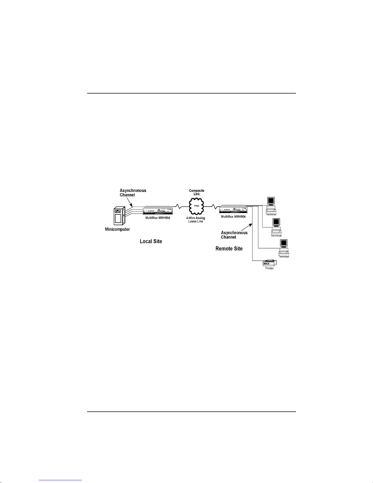
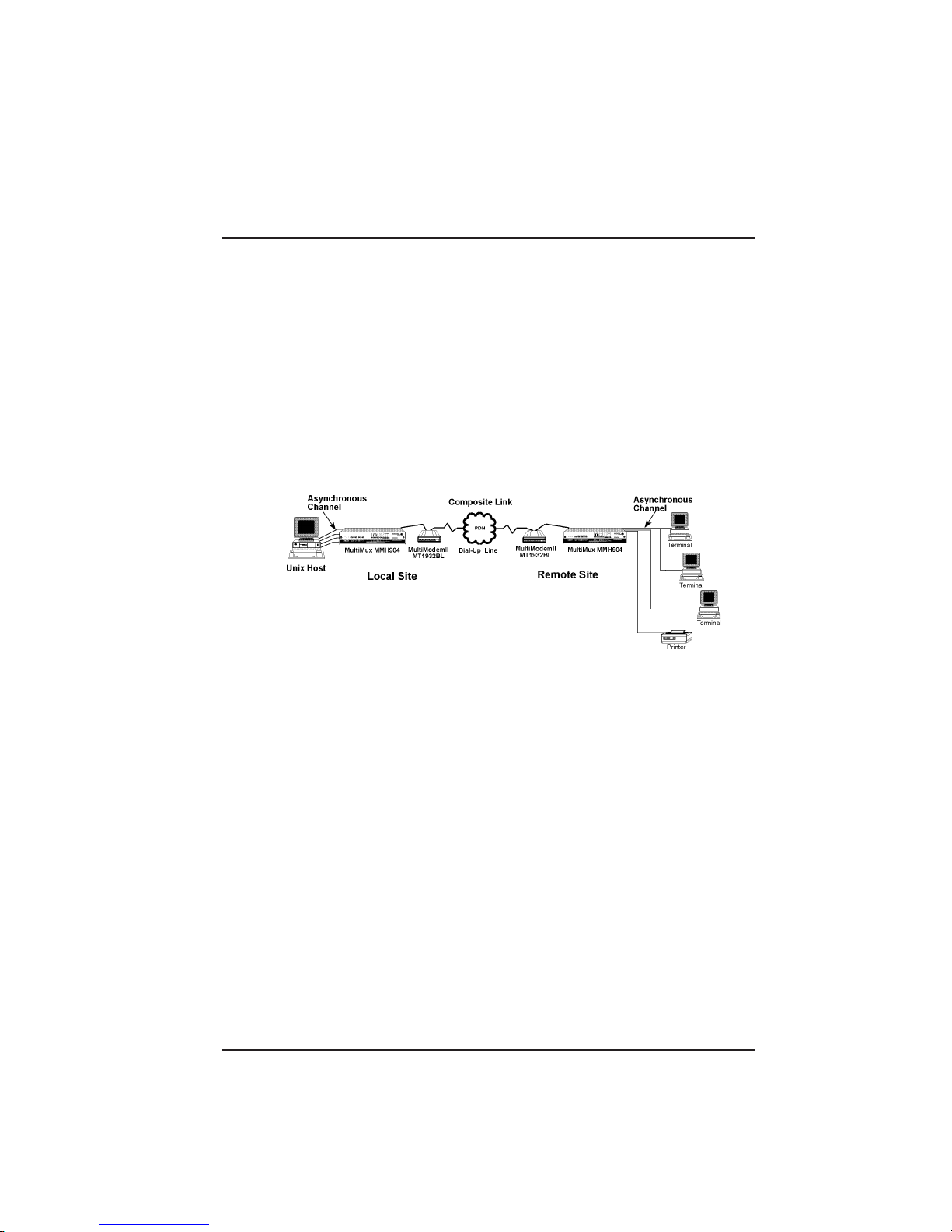
2.2 Configuration 1
Configuration 1 is two Multi-Tech MultiMux MMH904Ca/144 which are
four channel multiplexers with internal 28.8K bps composite link modems
linking sites one and two over a 4-wire analog lease line. The local site
has the MMH904Ca/288 connected to a host minicomputer. The remote
site has three terminals and a shared printer connected to the
asynchronous channels of the remote mux. At the remote site, the three
terminals are communicating with the remote mux on 38.4K bps
asynchronous channels and the printer is configured for one setting
above its cps rating. Configuration 1 is shown in Figure 2-1.
Figure 2-1. Configuration 1
Channels 1 through 4 at the local site are connected to channels 1
through 4 at the remote site. The asynchronous channels of the local
mux are configured with XON/XOFF software flow control enabled, so
that the channel buffers in the local mux do not lose data from the host.
With flow control enabled at the local mux, the local mux can tell the host
when it feels that it's dynamic buffers are becoming full. For the same
reasoning, pacing should be enabled at the remote site, if it appears that
data is being lost at the terminals. Pacing allows the terminal to tell the
remote mux not to send any more data until its buffers are cleared.
Pacing should also be active for the printer to ensure that all the data is
received by the printer. The first set of parameters in the following
examples are for the local mux and the second set are for the remote
mux.
28
Page 29

Chapter 2 - Configuration
Local Channel Parameter
CHN SPD WORD BIT PARITY CONTROL ACK ECHO PACE E IA XON
01 19200 8 1 NONE XON/XOFF OFF OFF OFF OFF OFF
02 19200 8 1 NONE XON/XOFF OFF OFF OFF OFF OFF
03 19200 8 1 NONE XON/XOFF OFF OFF OFF OFF OFF
04 19200 8 1 NONE XON/XOFF OFF OFF OFF OFF OFF
OK
STP FLOW ENQ/ PASS PASS
Configuration 1 Local Site Channel Parameters
Local Channel Parameter
CHN SPD WORD BIT PARITY CONTROL ACK ECHO PACE EIA XON
01 19200 8 1 NONE XON/XOFF OFF OFF XON OFF OFF
02 19200 8 1 NONE XON/XOFF OFF OFF XON OFF OFF
03 19200 8 1 NONE XON/XOFF OFF OFF XON OFF OFF
04 19200 8 1 NONE XON/XOFF OFF OFF XON OFF OFF
OK
STP FLOW ENQ/ PASS PASS
Configuration 1 Remote Site Channel Parameters
29
Page 30
Chapter 2 - Configuration
2.3 Configuration 2
Configuration 2 is two MultiMux MMH904Ca four channel multiplexers
with two external Multi-Tech MultiModemII MT2834BLs linking the two
sites over an async dial-up line. The MultiModemII's are connected to
the dial-up line and the RS232C interface from the modems is connected
to the EXTERNAL COMPOSITE LINK connector on the back panel of
the MMH904Ca's. The MH904Ca's are set up for an external link device
with a maximum link speed of 57,600 bps. The maximum link speed is
dependent on the compressibility of the data over the link. The
MultiModemIIs are set up for data compression and error correction in
order to achieve the link speed.
Figure 2-2. Configuration 2
The External Composite Link LEDs on the lower left side of the front
panel and the SYSTEM ASYNC LINK LED in the middle of the front
panel of the MMH904Ca's are active for this configuration. The channels
are set up with the same considerations as in Configuration 1.The
composite link configuration may be changed using the List Composite
Link Configuration ($L) command which is shown in the following
example.
LINK LINK MUX MUX EOF XMT EOF RCV LOOP
DEVICE FORMAT SPEED CLOCKING CHARACTER CHARACTER BACK
EXTERNAL ASYNC 57600 EXTERNAL FF FF OFF
Configuration 2 Composite Link Configuration
30
Page 31

Chapter 2 - Configuration
2.4 Configuration 3
Configuration 3 is two MultiMux MMH908Ca/56 eight channel
multiplexers connecting a minicomputer at the local site to eight remote
terminals over a digital composite link. The MMH908Ca/56s have
internal 56K bps Digital Service Units (DSUs) tieing the MultiMuxes to
the Digital Data Service (DDS) network provided by your teleco facility .
The DDS network is connected to the MMH908Ca/56s at the INTERNAL
COMPOSITE LINK DIGITAL DSU connector on the back panel of the
MultiMuxes. The composite link is set for DDS clocking.
Figure 2-3. Configuration 3
The INTERNAL LINK DEVICE DSU LED in the middle of the front panel
of the MMH908Ca's is lit for this configuration. The channels are set up
with the same considerations as in Configuration 1. The List Composite
Link Configuration ($L) command is shown in the following example for
an internal DSU.
LINK LINK MUX MUX EOF XMT EOF RCV LOOP
DEVICE FORMAT SPEED CLOCKING CHARACTER CHARACTER BACK
DSU SYNC 64000 DSU N/A N/A OFF
31
Page 32

Chapter 2 - Configuration
Configuration 3 Composite Link Configuration
Local Channel Parameter
CHN SPD WORD BIT PARITY CONTROL ACK ECHO PACE EIA XON
01 19200 8 1 NONE XON/XOFF OFF OFF OFF OFF OFF
02 19200 8 1 NONE XON/XOFF OFF OFF OFF OFF OFF
03 19200 8 1 NONE XON/XOFF OFF OFF OFF OFF OFF
04 19200 8 1 NONE XON/XOFF OFF OFF OFF OFF OFF
05 19200 8 1 NONE XON/XOFF OFF OFF OFF OFF OFF
06 19200 8 1 NONE XON/XOFF OFF OFF OFF OFF OFF
07 19200 8 1 NONE XON/XOFF OFF OFF OFF OFF OFF
08 19200 8 1 NONE XON/XOFF OFF OFF OFF OFF OFF
OK
STP FLOW ENQ/ PASS PASS
Configuration 3 Local Site Channel Parameters
Local Channel Parameter
CHN SPD WORD BIT PARITY CONTROL ACK ECHO PACE EIA XON
01 19200 8 1 NONE XON/XOFF OFF OFF XON OFF OFF
02 19200 8 1 NONE XON/XOFF OFF OFF XON OFF OFF
03 19200 8 1 NONE XON/XOFF OFF OFF XON OFF OFF
04 19200 8 1 NONE XON/XOFF OFF OFF XON OFF OFF
05 19200 8 1 NONE XON/XOFF OFF OFF OFF OFF OFF
06 19200 8 1 NONE XON/XOFF OFF OFF OFF OFF OFF
07 19200 8 1 NONE XON/XOFF OFF OFF OFF OFF OFF
08 19200 8 1 NONE XON/XOFF OFF OFF OFF OFF OFF
OK
STP FLOW ENQ/ PASS PASS
Configuration 3 Remote Site Channel Parameters
32
Page 33

Chapter 3 - Front & Rear Panel
Descriptions
Page 34

Chapter 3 - Front & Rear Panel Descritpions
3.1 Introduction
This chapter describes all of the front panel LEDs, switches, jumpers
and the shunt on the base and the back panel connectors. The front
panel contains all the LEDs for all the MultiMux MMH900 Series models.
Some of the LEDs on your particular model will not be active, for
example, if you have an internal composite link modem, the External
Composite Link LEDs on the lower left side of the control panel will not
light. Also, on the back panel, not all of the connectors are used in
agiven configuration.
3.2 Front Panel
The MultiMux is equipped with a complete set of LED status indicators
and DIP switches located behind the front panel. The status indicators
show precisely what is occurring in the network at all times. By
periodically checking the indicators you can keep abreast of system
activity without tieing up a channel device or using the supervisory
console. The front panel indicators are divided into four main categories;
the Command Modem, External Composite Link device, Internal
Composite Link device and the system status indicators. The function of
each indicator by category is explained in section 3.3.
Command Modem
RCV
CD
External Composite Link
CD
RCV
A
R
BUFFER
E
FULLNESS
O
T
LEVEL
R
A
N
S
XMTRCV XMTRCV XMTRCV
RCV
XMTRCV
Channel Eight
RCV XMTXMTRCV
Channel Six Channel Seven
Channel Five
XMT
OH
RCV
XMT
DTR
Channel one
V.35
Channel Two Channel Three Channel Four
XMT
CTS
XMT
M
IT
2
1
3
Internal Composite Link
ISDN
MMH2834 CD RCV XMT CTS 28.8 24.0 19.2 14.4 OH TR EC DBUP
DSU CD RCV XMT CTS 56 19.2 RTS NS OOS TM
V29/V33 CD RCV XMT CTS
INTERNAL LINK DEVICE
F
R
T
L
S
L
E
E
I
(Modems)
M
Y
S
N
C
T
R
L
R
C
V
V
O
N
T
K
2
T
C
E
9
A
/
L
M
L
D
D
V
A
O
I
W
S
R
D
3
N
N
M
U
E
3
K
MultiTech
M
M
H
I
2
S
8
D
3
N
4
Systems
MultiMux
Statistical Multiplexer
Figure 3-1. MultiMux Front Panel
34
Page 35

Chapter 3 - Front & Rear Panel Descritpions
3.3 LED Indicators
Command Modem
Indicator Description
CD Indicates the local command modem has detected a
carrier signal from a remote modem.
RCV/XMT Indicates that the command modem is on-line by
flashing with data activity between the two command
modems.
OH Indicates that the dial-up line for the command
modem is off-hook.
DTR Indicated that the command modem is ready to
communicate.
External Composite Link
CD The Carrier Detect (CD) indicator is used when the
MultiMux MMH900 series is configured for an
external composite link device and a carrier signal is
detected.
RCV/XMT The Transmit (XMT) and Receive (RCV) indicators
are used when the MultiMux MMH900 series is
configured for an external composite link device and
the network is on-line by flashing with data activity
between the two multiplexers.
CTS The Clear To Send (CTS) indicator is used when the
MultiMux MMH900 series is configured for an
external composite link device and the composite
link device is ready to transmit data.
V.35 The V.35 indicator is used when the MultiMux
MMH900 series is configured for an external
composite link device which uses a V.35 interface.
The V.24/V.35 shunt has to be in the V.35 position
for this LED to light.
35
Page 36

Chapter 3 - Front & Rear Panel Descritpions
Channel
Indicator Description
Channel 1-8 The Channel Receive (RCV) and Transmit RCV/
XMT(XMT)indicators show the activity level on each
channel.MultiMux MMH904 uses Channel One
through Channel Four indicators. The MultiMux
MMH908 can connect up to eight async devices
which use Channel One through Channel Eight
indicators.
Internal Composite Link (MMH2834 Modem)
Indicator Description
CD The Carrier Detect (CD) indicator lights when the
MMH2834 composite link modem detects a carrier
signal from the remote link modem.
XMT The Transmit (XMT) indicator flashes as data is
being transmitted by the MMH2834 modem to the
remote multiplexer.
RCV The Receive (RCV) indicator flashes as data is
being received by the MMH2834 modem from the
remote multiplexer.
CTS The Clear To Send (CTS) indicator lights when the
MMH2834 composite link modem is ready to
transmit data.
28.8, 24.0, These composite link speed indicators display
19.2, 14.4 the receive baud rate of the internal composite link.
OH The Off-Hook (OH) indicator lights when the
composite link is off-hook
TR The Terminal Ready (TR) indicator lights when the
MMH2834 modem is permitted to answer an
incoming call. When the indicator goes off, the
connected composite link modem will disconnect.
EC The Error Correction (EC) indicator is on solid when
the MMH2834 modem is in errorcorrection mode
and flashes on and off when compression is active.
DBUP The Dial Back up (DBUP) indicator lights when the
MMH2834 modem is in dial back up mode.
36
Page 37

Chapter 3 - Front & Rear Panel Descritpions
Internal Composite Link (DSU)
Indicator Description
CD The Carrier Detect (CD) indicator lights when the
composite link DSU detects a carrier signal from the
remote MultiMux.
XMT The Transmit (XMT) indicator flashes as data is
being transmitted to the remote multiplexer on the
composite link.
RCV The Receive (RCV) indicator flashes as data is
being received from the remote multiplexer on the
composite link.
CTS The Clear To Send (CTS) indicator lights when the
composite link DSU is ready to transmit data.
56, 19.2 These composite link speed indicators display the
baud rate of the internal composite link.
RTS The Request To Send (RTS) indicator lights when
the MultiMux has data it wants to transmit over the
composite link
NS The No Signal (NS) indicator lights when no signal
at all is received from the DDS line or when the
signal is too weak for normal operation. This
indicator will also flash to indicate that errors have
been detected when using the Test Pattern
diagnostic feature.
OOS The Out Of Service (OOS) indicator lights when an
out of service signal is detected from the teleco.
TM The Test Mode (TM) indicator lights when the DSU
is placed in test mode.
Internal Composite Link (V29/V33 Modem)
Indicator Description
CD The Carrier Detect (CD) indicator lights when an
XMT The Transmit (XMT) indicator flashes as data is
internal composite link 9600 or 14,400 bps modem
detects a carrier signal from the remote link modem.
being transmitted from an internal composite link
9600 or 14,400 bps modem to a remote multiplexer.
37
Page 38

Chapter 3 - Front & Rear Panel Descritpions
RCV The Receive (RCV) indicator flashes as data is
being received by an internal composite link 9600 or
14,400 bps modem from a remote multiplexer.
CTS The Clear To Send (CTS) indicator lights when an
internal composite link 9600 or 14,400 modem is
ready to transmit data.
Internal Composite Link (ISDN)
Indicator Description
CD The Carrier Detect (CD) indicator lights when the
terminal adapter establishes a connection with the
remote unit.
XMT The Transmit (XMT) indicator flashes as data is
being transmitted to a remote multiplexer.
RCV The Receive (RCV) indine line, or modem problem).
Steady when buffer overflow conditions exist.
REMOTE DWN The local mux cannot establish communications with
the remote mux.
TEST MODE A device in the network is currently running a
maintenance diagnostic.
ASYNC LINK The composite link is configured to transfer data in
asynchronous mode.
Internal Link Device (Modems)
Indicator Description
56K DSU This indicator lights when the internal link device is a
DSU.
V29/V33 This indicator lights when either an internal 9600 bps
(V.29) or 14,400 bps (V .33) modem is the composite
link device.
MMH2834 This indicator lights when the 28.8K bps internal
composite link modem is the composite link device.
ISDN This indicator lights when the internal link device is
the ISDN terminal adapter.
38
Page 39

Chapter 3 - Front & Rear Panel Descritpions
3.4 Back Panel
The cable connections for the MultiMux are made at the back panel.
Refer to Chapter 4 for cabling installation procedures. Refer to Appendix
C for cabling diagrams. The MultiMux back panel is shown in Figure 3-2.
COMMAND
MODEM
DIAL-UP
I
O
DIAL UP LEASED DIGITAL
MODEM DSU
COMMAND PORT CHANNEL 8
COMPOSITE LINK
INTERNAL
EXTERNAL
RS232C/V.35
CHANNEL 4
CHANNEL 7
CHANNEL 3
CHANNEL 6
CHANNEL 2
CHANNEL 5
CHANNEL 1
Figure 3-2. Back Panel
3.4.1 ON/OFF Switch
This switch provides AC power to the MultiMux when placed in the up
(ON) position and removes power when in the down position.
3.4.2 Power Connector
The power connector is a receptacle for a 3-prong grounded power cord.
3.4.3 COMMAND MODEM DIAL-UP Connector
This connector is used when the command modem is connected to a
separate dial-up line for remote access.
3.4.4 COMMAND PORT Connector
The command port connector is used to connect the supervisory console
to the MultiMux MMH900 series. The supervisory console can be either
an ASCII terminal or a pc with a serial port running communications
software. The command port connector has a DCE physical interface
with a DB25 female connector.
3.4.5 COMPOSITE LINK INTERNAL MODEM
This composite link internal modem connector is used with an internal
composite link modem with a dial-up or dial back capability . This
connector provides an RJ1 1 connection.
DIAL-UP Connector
39
Page 40

Chapter 3 - Front & Rear Panel Descritpions
3.4.6 COMPOSITE LINK INTERNAL MODEM
LEASED Connector
This connector is used when the MultiMux MMH900 series is connected
to a lease line with an internal Multi-Tech 9600, 14.4K, or 28.8K bps
modem installed. The composite link internal modem leased connector
provides an RJ1 1 connection.
3.4.7 COMPOSITE LINK INTERNAL DIGITAL
DSU Connector
The composite link internal digital DSU connector is used when the
MultiMux MMH900 series is connected to a DDS or dedicated network
and an internal DSU is installed. This connector provides an RJ48
connection to the DDS or dedicated network.
3.4.8 COMPOSITE LINK EXTERNAL RS232C/
V.35 Connector
This connector is used when an external modem or DSU is connected to
the MultiMux MMH900 series. This connection can be either RS232C or
V.35. If the connection is V.35, then the shunt must be moved from the
RS232C position to the V.35 position. This connector is a DB25 female
connection.
3.4.9 CHANNEL 1 - CHANNEL 8 Connectors
Channel 1 through channel 8 connectors are used to connect the async
devices to the MultiMux MMH900 series. The MultiMux MMH904 has
four channel connectors. The MultiMux MMH908 has eight channel
connectors. These connectors provide the RS232C connection.
40
Page 41

Chapter 3 - Front & Rear Panel Descritpions
3
3.5 Switches/Jumper/Shunt
Switch settings can be changed by taking off the front panel. To change
the RKWL/144 jumper, V.24/V.35 shunt, V.29/V .33 shunt, or the 2834
shunt, the front panel and top cover need to be removed. The switches,
jumper and shunts are shown on the base in Figure 3-3.
2834
V.24 Shunt
V29/V33
Power
Supply
V.29/V.3
Shunt
2834 Shunt
1 2 3 4 5 6 7 8
8-Position
DIP Switch
OTHER RKWL14.4
Composite
Link Internal
Modem Jumper
1 2 3 4
4-Position
DIP Switch
V.35 Shunt
V.35 V.24
Figure 3-3. Base
3.5.1 8-Position DIP Switch
The 8-position DIP switch is shown in Figure 3-3 and the function of
each position is as follows:
Switch position 1: Closed Initiate Downline Load Off
Open (UP) Initiate Downline Load On
(used for downline loading only)
Switch position 2: Closed External Link Device Selected
Open (UP) Internal Link Device Selected
Switch Position 3: Closed Four Channel Operation
Open (UP) Eight Channel Operation
Switch Position 4: Closed Disable Command Modem Remote
Access
Open (UP) Enable Command Modem Remote
Access (default)
Switch Position 5: Not Used
41
Page 42

Chapter 3 - Front & Rear Panel Descritpions
With an MMH904 Unit
C = Closed O = Open (Up)
Channel # 1-4 5-8 9-12 13-16 17-20 21-24 25-28 29-32
Switch Position 6: C O C O C O C O
Switch Position 7: C C O O C C O O
Switch Position 8: C C C C O O O O
With an MMH908 Unit
Channel # 1-8 9-16 17-24 25-32
Switch Position 6: C O C O
Switch Position 7: C C O O
Switch Position 8: CCCC
3.5.2 4-Position DIP Switch
The four-position DIP switch determines the type of MultiMux at the other
end of the composite link. The function of the switch is as follows:
Remote Mux MM16/32 MM900 MMH16/32 MH900
Switch Position 1: O C O C
Switch Position 2: O O C C
Switch Position 3: Not Used
Switch Position 4: Not Used
42
Page 43

Chapter 3 - Front & Rear Panel Descritpions
(Factory Default)
L
3.5.3 144RKWL/OtherJumper
The 144 RKWL/OTHER jumper is positioned in the 144RKWL (Rockwell)
position when a 14,400 Rockwell internal composite link modem is used.
When any other internal composite link modem or DSU is used, this
jumper is in the OTHER position. The location of the jumper on the base
is shown in Figure 3-3 and the placement of the jumper is shown in
Figure 3-4.
OTHER/144RKWL
All other Internal
composite link
modems installed
OTHER/144RKW
14400 Rockwell
Modem Install
(Optional Setting)
Figure 3-4. 144RKWL/Other Jumper
3.5.4 V.24/V.35 Shunt
An external composite link device with either an RS232C/V.24 or a V.35
interface can be connected to a MultiMux MMH900 series. When an
external composite link device with an RS232C/V.24 interface is
connected to the MultiMux, the V.24 shunt should be installed. When the
external composite link device has a V.35 interface, the V.35 shunt
should be installed. The V.24/V.35 shunt is shown in Figure 3-3. The
factory default for the shunt is in the V.24 position.
3.5.5 V.29/V.33 Shunt and 2834 Shunt
When an internal modem is being installed, the V.29/V.33 shunt or the
2834 shunt has to be in the correct position. This shunt is shown in
Figure 3-3. If a V.29 or V.33 modem is being installed, the shunt has to
be in the V.29/V.33 position. If a MMH2834 modem is being installed,
the shunt has to be in the 2834 position. If an internal ISDN terminal
adapter is installed, the shunt must be in the 2834 position.
43
Page 44

Chapter 4- Installation
Page 45

Chapter 4 - Installation
4.1 Introduction
This chapter explains how to unpack and install your MultiMux cabinet.
4.2 Safety Warnings
1. Never install telephone wiring during a lightning storm.
2. Never install telephone jacks in wet locations unless the jack is
specifically designed for wet locations.
3. Never touch uninsulated telephone wires or terminals unless the
telephone line has been disconnected at the network interface.
4. Use caution when installing or modifying telephone lines.
5. Avoid using a telephone (other than a cordless type) during an
electrical storm. There may be a remote risk of electrical shock from
lightning.
6. Do not use the telephone to report a gas leak in the vicinity of the
leak.
4.3 Unpacking
Unpack and check all the items in the MultiMux shipping list to ensure
that you have received the correct options and accessories.
MultiMux Components
A. MultiMux Cabinet
B. User Guide
C. Power cord
D. RJ1 1 phone cable (for internal modem)
E. RJ48 phone cable (for internal DSU)
F. Mux Converter Cable (for internal ISDN terminal adapter)
G. Composite Link cable ( for external modem)
Inspect the MultiMux cabinet for visible shipping damage. If damage is
observed, do not power-on the unit; refer to Chapter 8 of this Guide and
contact Multi-Tech's Tech Support for advice. If no damage is observed,
place the MultiMux cabinet in its final location.
Save the packing material for possible future use (e.g., return or
relocation).
45
Page 46

Chapter 4 - Installation
4.4 Installation
T able 4-1. Installation Procedure
Composite Link Installation
1 MultiMux has an internal link modem and are connecting to a
dial-up service: Connect the RJ11 cable to the COMPOSITE LINK
INTERNAL MODEM DIAL-UP connector on the back panel of the
MultiMux and your phone line.
MultiMux has an internal link modem and are connecting to a
leased line service: Connect the RJ1 1 cable to the COMPOSITE
LINK INTERNAL MODEM LEASED connector on the back panel of
the MultiMux and your phone line.
MultiMux has an internal link DSU and are connecting to a DDS
or dedicated service: Connect the RJ1 1 cable to the COMPOSITE
LINK INTERNAL DIGITAL connector on the back panel of the
MultiMux and your phone line.
MultiMux has an internal link ISDN terminal adapter: Connect the
Mux Converter cable supplied with the unit to the COMPOSITE LINK
INTERNAL DIGITALconnector on the back panel of the MultiMux
and your phone line.
MultiMux is being connected to an external modem with an
RS232C interface: Connect the composite link cable shipped with
your MultiMux to the COMPOSITE LINK EXTERNAL RS232C/V.35
connector on the back panel and to the RS232 connector on the
external modem.
MultiMux is being connected to an external modem with a V.35
interface: Connect a V.35 interface adapter cable Multi-T ech
(#90056210) to the COMPOSITE LINK EXTERNAL RS232C/V.35
connector on the back panel and to the V.35 connector on the
external modem.
I
O
COMMAND
MODEM
DIAL-UP
COMPOSITE LINK
INTERNAL
DIAL UP LEASED DIGITAL
MODEM DSU
INTERNAL
DIAL UP LEASED DIGITAL
MODEM DSU
COMMAND PORT CHANNEL 8
CHANNEL 4
EXTERNAL
RS232C/V.35
COMPOSITE LINK
RS232C/V.35
CHANNEL 7
CHANNEL 3
CHANNEL 6
CHANNEL 2
CHANNEL 5
CHANNEL 1
Figure 4-1. Composite Link Cabling
46
Page 47

Chapter 4 - Installation
3
External modem with V.35 interface is being connected: Remove
the top cover and move the V.24/V.35 shunt from the V.24 position to
the V.35 position. Replace the top cover.
1 2 3 4 5 6 7 8
OTHER RKWL14.4
V.35 Shunt
MultiTech
MMH956
1 2 3 4
Systems
V.35 V.24
2834
V.24 Shunt
V29/V33
V.29/V.3
Shunt
2834 Shunt
Figure 4-2. Shunts
2 Connect the AC power cord shipped with your MultiMux to the AC
power connector on the back panel and to the AC outlet.
3 Press the power ON/OFF switch on the back panel of the MultiMux
to apply power.
4 If the internal composite link modem is V .34/28800 bps, verify that
the INTERNAL LINK DEVICE Modem MMH2834 LED on the front
panel is ON.
If your MultiMux is configured for an external composite link sync
modem, verify that the External Composite Link XMT and CTS LEDs
are ON. If the external composite link modem has a V.35 interface,
verify that the V.35 LED is also ON.
If a DSU is installed in your MultiMux, verify that the 56K DSU LED
is ON.
47
Page 48

Chapter 4 - Installation
Supervisory Console
5 If you are connecting a supervisory console to the MultiMux, connect
a terminal or PC to the COMMAND PORT connector via an
appropriate RS232C cable. The PC needs to be running
communications software.
Note: Any cables connected to the computer should be shielded to
reduce interference.
I
O
COMMAND
MODEM
DIAL UP LEASED DIGITAL
DIAL-UP
MODEM DSU
COMMAND PORT
COMPOSITE LINK
INTERNAL
EXTERNAL
RS232C/V.35
CHANNEL 8
CHANNEL 4
CHANNEL 7
CHANNEL 3
CHANNEL 6
CHANNEL 2
CHANNEL 5
CHANNEL 1
COMMAND PORT
Figure 4-3. Supervisory Console Cabling
6 Apply power to the supervisory console and enter AT and then hit
Return. If you get an OK message back, you are communicating
with the Command Port..
Command Modem
7 To connect the built-in command modem to a standard phone line,
connect the RJ1 1 cable to the COMMAND MODEM DIAL-UP
connector on the back panel of the MultiMux and the phone jack.
I
O
COMMAND
MODEM
DIAL-UP
COMPOSITE LINK
INTERNAL
DIAL UP LEASED DIGITAL
MODEM DSU
COMMAND
MODEM
DIAL-UP
COMMAND PORT CHANNEL 8
EXTERNAL
RS232C/V.35
CHANNEL 4
CHANNEL 7
CHANNEL 3
CHANNEL 6
CHANNEL 2
CHANNEL 5
CHANNEL 1
Figure 4-4. Command Modem Cabling
48
Page 49

Chapter 4 - Installation
Channel
8 Route and connect your channel devices to the MultiMux back panel
CHANNEL 1 - CHANNEL 4 on a MultiMux MMH904 or CHANNEL 1
- CHANNEL 8 on aMultiMux MMH908 connectors using RS232
cables. Do this at both of your sites, so that channel 1 at one site
communicates with channel 1 at the other site, and so on.
Note: Any cables connected to the computer should be shielded to
reduce interference.
Follow channel device guidelines regarding RS232 cable lengths
and make sure that the pin assignment in Appendix C of this manual
are followed.
I
O
COMMAND
MODEM
DIAL-UP
INTERNAL
DIAL UP LEASED DIGITAL
MODEM DSU
COMPOSITE LINK
COMMAND PORT CHANNEL 8
CHANNEL 4
EXTERNAL
RS232C/V.35
CHANNEL 7
CHANNEL 3
Channels
CHANNEL 6
CHANNEL 2
CHANNEL 5
CHANNEL 1
Figure 4-5. Channel Cabling
9 Execute the parameter display command to display the current
channel parameter status for your local MultiMux by entering the
following:
A T L (press Return)
The following will be displayed on your supervisory console for a
MultiMux MMH904:
Local Channel Parameter
CHN SPD WORD BIT PARITY CONTROL ACK ECHO PACE EIA XON
01 19200 8 1 NONE XON/XOFF OFF OFF OFF OFF OFF
02 19200 8 1 NONE XON/XOFF OFF OFF OFF OFF OFF
03 19200 8 1 NONE XON/XOFF OFF OFF OFF OFF OFF
04 19200 8 1 NONE XON/XOFF OFF OFF OFF OFF OFF
STP FLOW ENQ/ PASS PASS
10 Based on the listed conditions for each channel, reconfigure the
parameters to match your actual channel requirements by entering
commands as described in Chapter 4.
As you change operational parameters, they will not actually be
incorporated into your running system until you execute a Store New
Parameters (&W).
49
Page 50

Chapter 4 - Installation
As you change operational parameters, they will not actually be
incorporated into your running system until you execute a Store New
Parameters (&W) command.
50
Page 51

Chapter 5 - Commands
Page 52

Chapter 4 - Installation
5.1 Introduction
This chapter presents a command summary followed by a detailed
description of each command used in the MultiMux. The structure of the
commands is that they all begin with the prefix AT. Each command line
may contain any number of commands in a string (no spaces) up to a
limit of 40 characters. Most commands include a value and are part of
the 40 character total. Hitting Return executes a command line but does
not incorporate it into the operation of your MultiMux. You must execute
a Store New Parameters command to implement your changes into your
mux network.
An example of a command line which changes the parameters of the
channel device connected to channel 1. The following command
changes the baud rate to 4800 bps, parity to odd, CTS flow control and
turns echo off.
ATC1B4800P2F1E0
Table 5-1 presents a summary of all the commands used in the
MultiMux. The commands are divided into a number of general
categories according to their functionality within the MultiMux. This
functional division is carried on into the detailed description of each
command.
The access commands for the command modem are described in this
chapter. The general A T commands for the command modem are
described in Appendix D.
T able 5-1. Command Summary
TYPE COMMAND DESCRIPTION
General H General Help
H1 Channel Parameter Help
H2 DIP-Switch Configuration Help
H3 Async/Sync Composite Link Format Help
H4 Additional Composite Link Help
H5 Miscellaneous Help
H6 Internal V.29/V.33 Composite Link Modem
Configuration Help
H7 Internal DSU Help
Z Reset
&W Store New Parameters to Memory
52
Page 53

T able 5-1. Command Summary (cont.)
TYPE COMMAND DESCRIPTION
Channel B0 Channel Off Command
Parameter Bxxx Baud Rate Select
C0 Universal Channel Parameters Command
C1-C8 Channel Select for Parameter Change
DCx Destination Channel
DNx Destination Node Number
E0 Echo Off
E1 Echo On
F0 Flow Control Off
F1 CTS (RS232C) Flow Control
F2 Xon/Xoff Flow Control
F3 Enq/Ack On
F4 EnqAck Off
F5 Pacing On
F6 Pacing Off
F7 Pass EIA (RS232C) Signals On
F8 Pass EIA (RS232C) Signals Off
F9 Xon Pass Thru On
F10 Xon Pass Thru Off
F11 Inverter DTR On
F12 Inverter DTR Off
F13 Xoff/First Character Pacing
F14 Xoff/Xon Character Pacing
F15 XPC Flow Control On
F16 XPC Flow Control Off
I0-2 Identification Commands
L,L0 List all Channel Parameters
L1-L8 List individual Channel
P0 Parity None
P1 Parity Odd
P2 Parity Even
Chapter 5 - Commands
53
Page 54

Chapter 5 - Commands
T able 5-1. Command Summary (cont.)
TYPE COMMAND DESCRIPTION
Channel R0-3 Response T ime Priority
Parameter SB1 Stop Bit 1
SB1.5 Stop Bit 1.5
SB2 Stop Bit 2
SN Local Source Node Number
WL5 Word Length 5
WL6 Word Length 6
WL7 Word Length 7
WL8 Word Length 8
&F Load Factory Defaults
&SL Select Local Parameter
&SR Select Downline Parameters
#S1-8 Channel Status Reports
Composite Link
#C Clear Composite Statistics
#CLA Composite Link Access
$F Load Factory Defaults for DSU and ISCC
#FT Flush Timer Value
$L List Composite Link Configuration
#L List Composite Link Settings
#RB Set Auto reporting Baud Rate
#RT Set Auto Reporting T ime Interval
#S Status Reporting
#S9 Status of Front Panel LEDs
Composite Link Format
#EOFR Receive End Of Frame Character
#EOFT Transmit End Of Frame Character
$MUXCL Mux Clock
$MUXSP Mux Speed
#SYNC Synchronous Composite Link
#ASYNC Asynchronous Composite Link
54
Page 55

T able 5-1. Command Summary (cont.)
TYPE COMMAND DESCRIPTION
Internal 9600/14.4K Composite Link Modem
$MC Modem Configuration Select
$EP Echo Protect Tone
$LA Link Amp Set
$LD Link Delay Set
$CQ Cable Equalization
$RL Receive Level
$TL Transmit Level
$T T/2 Adaptive Equalizer
$W W rite Configurations to modem
Internal MMH2834 Modem Configuration
$M(ASYNC/SYNC) MMH2834 Sync or Async Mode
$M(DIAL/LEASED) Dail up or leased line
$MWIRE(2/4) 2 or 4 wire leased line
$MTL(0/10) Transmit Level 0 or -10 db
$M (ANSWER/ORIGINATE) Lease Line Answer or
Originate Mode
$MCOMMAND Enables or disables Command
Mode
$MTR Data Transmission Rate
Internal DSU
$DSUCL Selects Clocking for Internal DSU
$DSUSP Selects Speed of Internal DSU
Test &T1-3 Memory Tests
&T4 Local Loop
&T5 Digital Loop
&T6 Remote Analog Loop
&T7 Switch and LEDs
&T8 Memory Test
&T9 Watch Dog Timer Test
&T10 Internal Modem Memory Test
Chapter 5 - Commands
55
Page 56

Chapter 5 - Commands
T able 5-1. Command Summary (cont.)
TYPE COMMAND DESCRIPTION
Command
Modem #MA Command Modem Select
#RA Remote Command Modem
Access
56
Page 57

Chapter 5 - Commands
5.2 Command Description
The following command descriptions explain the effect that executing
each command has on your MultiMux network. Refer to Chapter 6 for
instructions on how to execute the commands.
5.2.1 General Commands
Z Reset
The Reset command will set the operating
parameters of the MultiMux to its most recently
stored values. Executing the Reset command
performs the same function in the logic as turning
power off and then on to the unit.
&W Store New Parameters
The Store New Parameters command causes the
MultiMux to store new parameters. Prior to
executing the &W command, any changes to
MultiMux parameters are temporary and do not
affect the unit’s operation until you execute the &W
command followed by a reset Z command. The &W
command stores the parameters in nonvolatile
memory and will take affect upon reset or powering
the MultiMux off and on.
H, H1-H8 Help
The Help commands are designed to give you short
explanations on how to use MultiMux commands.
They will be useful if your manual is not handy ,
although the explanations are quite short in
comparison to those in the manual. When a Help
command is executed in conjunction with some
other command, the resulting display will explain
options and information for that command. The
General Help command provides information on the
other MultiMux Help commands.
57
Page 58

Chapter 5 - Commands
The H command menu is as follows:
General Help
- Each command line must begin with the prefix AT.
- Each command line may contain any number of commands up to
40
characters total.
- Most command letters must be followed by a value.
- For help on specific commands, enter "ATH" followed by one of the
command letters.
A TH1 for channel parameter commands.
A TH2 to view the DIP switch configurations.
A TH3 for async and sync composite link format commands.
A TH4 for additional composite link commands.
A TH5 for miscellaneous commands.
A TH6 for internal V.29/V.33 composite link modem commands.
A TH7 for internal DSU commands.
A TH8 for internal MMH2834 modem commands
For additional help menus, enter one of the following ATH codes to
obtain the desired information:
A TH or ATH0 for General Help.
58
Page 59

The H1 Menu is as follows:
CHANNEL PARAMETER COMMANDS
B BAUD RATE SELECTION
P PARITY SELECTION
C CHANNEL SELECTION
R RESPONSE TIME PRIORITY
DC DEST. CHANNEL SELECTION
SB STOP BIT SELECTION
DN DEST. NODE SELECTION
SN LOCAL SOURCE NODE NUMBER
E LOCAL ECHO
#S CHANNEL STATISTICS
F FLOW CONTROL
&SL SELECT LOCAL PARAMETERS
&F READ IN FACTORY DEFAULTS
&SR SELECT DOWNLINE LOAD PARAMETERS
L LIST P ARAMETERS
Chapter 5 - Commands
WL WORD LENGTH SELECTION
The following example will select CHANNEL 1 and set its baud rate to
2400 and the WORD LENGTH to 8 bits:
ATC1B2400WL8 <ENTER>
For HELP on a specific command, enter “ATH” followed by a command
letter.
59
Page 60

Chapter 5 - Commands
The H2 Menu is as follows:
MUL TIMUX Eight Position DIP-Switch Definitions and Settings
Switch 1 Switch 2 Switch 3 Switch 4 Switch 5 Switch 6, Switch 7, Switch 8
Initiate Link 8/4 Remote Not Channel Group Select
Dwn Device Channel Access Used When MM16 or MMH16
Line Series is selected
Load
UP = ON INTERNAL 8 CHAN ENABLED SEE TABLE BELOW
DN = OFF EXTERNAL 4 CHAN DISABLED
CURRENT SETTINGS:
SW#6 DN UP DN UP DN UP DN UP
SW#7 DN DN UP UP DN DN UP UP
SW#8 DN DN DN DN UP UP UP UP
SW#6 DN UP DN UP
SW#7 DN DN UP UP
SW#8 DN DN DN DN
DN DN DN DN DN DN DN DN
1 - 4 5 - 8 9 - 12 13 - 16 17 - 20 21 - 24 25 - 28 29 - 32
1 - 8 9 - 16 17 - 24 25 - 32
Note: Hit any key to display four position DIP Switch or control C to
abort MultiMux four position DIP Switch definitions and configurations.
Switch 1 Switch 2 Switch 3 Switch 4
Mux Mode Mux Mode Not Not
Select Select Used Used
UP = 16/32 MM
DN = 900 MMH/MMV
Current Setting:
DN DN DN DN
60
Page 61

Chapter 5 - Commands
The H3 Mend is as follows:
COMPOSITE LINK FORMAT COMMANDS
#EOFR - SELECTS RECEIVE END OF FRAME CHARACTER FOR
ASYNC LINK.
#EOFT - SELECTS TRANSMIT END OF FRAME CHARACTER FOR
ASYNC LINK.
$MUXCL - SELECTS INT/EXT CLOCKING OF MUX COMPOSITE
LINK.
$MUXSP - SELECTS SPEED OF MUX COMPOSITE LINK WHEN MUX
CLOCKING IS INTERNAL OR ASYNC LINK IS SELECTED.
#SYNC - SELECTS SYNC COMPOSITE LINK
#ASYNC - SELECTS ASYNC COMPOSITE LINK
For HELP on a specific command, enter "ATH" followed by the command
letter:
EXAMPLE: ATH$MUXCL "ENTER"
The H4 Menu is as follows:
COMPOSITE LINK COMMANDS
#C CLEAR COMPOSITE STATISTICS
#CLA COMPOSITE LINK ACCESS
#DTR TOGGLE DTR ON THE COMPOSITE LINK
$F LOAD FACTORY DEFAULTS FOR DSU AND ISCC
#FT FLUSH TIMER VALUE
$L LIST COMPOSITE LINK CONFIGURATION
#L LIST COMPOSITE LINK SETTINGS
R RESPONSE TIME PRIORITY
#RB SET AUTO REPORTING BAUD RATE
#RT S ET AUTO REPORTING TIME INTERVAL
61
Page 62

Chapter 5 - Commands
#S STATUS REPORTING
#S9 STATUS OF FRONT PANEL LEDS
For HELP on a specific command, enter “ATH” followed by a command
letter.
The H5 Menu is as follows:
MISCELLANEOUS COMMANDS
I ID CODE
#MA MODEM ACCESS FOR COMMAND MODEM
#RA REMOTE ACCESS FOR COMMAND MODEM
&T TEST MODES
&W SAVE PARAMETERS "WRITE TO MEMORY"
Z RESET MULTIMUX
For HELP on a specific command, enter “ATH” followed by a command
letter.
The H6 Menu is as follows:
Commands to configure the MultiMux Internal V29/V33 modem
$CQ CABLE EQUALIZER
$EP ECHO PROTECTOR CONTROL
$F READ IN FACTORY DEFAULTS FOR MODEM
$L LIST INTERNAL MODEM PARAMETERS
$LA LINK AMPLITUDE EQUALIZER
$LD LINK DELAY EQUALIZER
$MC MODEM SPEED CONFIGURATION
$RL MODEM RECEIVE LEVEL
$TL MODEM TRANSMIT LEVEL
$T (T/2) ADAPTIVE EQUALIZER
$W WRITE CONFIGURATIONS T O MODEM #DOES NOT
SAVE#
62
Page 63

Chapter 5 - Commands
The H7 Menu is as follws:
INTERNAL DSU COMMANDS
#DSUCL SELECTS CLOCKING FOR INTERNAL DSU.
#DSUSP SELECTS SPEED FOR INTERNAL DSU.
For HELP on a specific command, enter “ATH” followed by a command
letter.
The H8 Menu is as follows:
INTERNAL MMH2834 COMMANDS
$M(ASYNC/SYNC) SYNC OR ASYNC.
$M(DIAL/LEASED) DIAL UP OR LEASE LINE
$MWIRE(2/4) 2 OR 4 WIRE LEASE LINE
$MMTL(0/1) TRANSMIT LEVEL 1 OR -10DB
$M(ANSWER/ORIGINATE) ANSWER OR ORIGINATE
MODE FOR LEASED LINE
$MCOMMAND(0/1) ENABLE OR DISABLE
COMMAND MODE
$MTR(28800/91200
/1440/9600) DATA TRANSMISSION RATE
For HELP on a specific command, enter “ATH” followed by a command
letter.
63
Page 64

Chapter 5 - Commands
5.2.2 Channel Parameter Commands
Command Description
BO Channel Off Command
The channel off command turns the selected
channel off. This command turns off a particular
channel or all channels depending on the
command. This allows the more efficient use of the
dynamically allocated buffers and allows the
multiplexer to skip the scanning of unused channels.
Bxxxx Baud Rate Select
The Bxxxxx command selects the bps rate on the
indicated channel. The channel bps rate is from 300
bps to 38.4K bps.
CO Universal Channel Parameters
The Universal Channel Parameters command
incorporates the commands that follow it (all prior to
a Carriage Return) into all the channels. This allows
you to change such conditions as baud rate, word
length, parity and flow control on all channels by
executing a single command.
C1-C8 Channel Select
The Channel Select command selects an individual
channel on which subsequent commands can
operate. The Channel Select command must
precede any of the other commands but remains in
effect until changed. This is so that a string
ofcommands can be entered without preceding each
one with a Cx command.
DCxx Destination Channel Number
This command is not necessary when a MultiMux
900 Series is connected to another MultiMux 900
series. The Destination Channel Number command
DCxx is necessary when an MMH904/MMH908 is
connected to a MultiMux16 or MultiMux 32 model.
The DCxx command specifies the destination
channel to which the source channel is
communicating. A specific channel can only
64
Page 65

communicate with one other channel. On multinode
networks, this command must be entered at both
channel locations specifying each other as
destinations (channels can pass through two nodes
to get to its destination). On point-to-point networks,
this parameter can be downline loaded.
DNxx Destination Node Number
This command is not necessary when a MultiMux
900 Series is connected to another MultiMux 900
Series. The destinatnion Node Number DNxx is
necessary when MMH904/MMH908 is connected to
a MultiMux16 or MultiMux32 model.
The DNxx command specifies the node number of
the destination node for output operations from a
local node. It specifies the destination node of the
channels to which the local source channels will
connect. For example, if some node in your network
is assigned 01 as its number (a node where its SN
command was SN01), you can communicate with
the 01 location channels by executing a DN01
command. At that point, your local channels will
communicate with those at node 01. The specific
channel connections will be determined by the
“virtual” channel number you have set up with the 8position DlP-Switch SW6, SW7, and SW8.
EO-1 Echo Command
The E0-E1 commands turn on and off the echoplex
feature of the MultiMux. When the echo condition is
on, the data entered on the channel keyboard is
returned to the channel display . The purpose of this
is so that in interactive operations an operator will
not experience undue delays in seeing data appear
on the monitor. When the echo condition is of f, the
keyboard data is not returned to the monitor. E1
turns on echoplex and E0 turns it off.
F0-F2 Flow Control Operations
Flow Control is the means by which data flow is
controlled from the channel devices into the
MultiMux. Flow Control is necessary when the data
handling capacity of an individual channel cannot
Chapter 5 - Commands
65
Page 66

Chapter 5 - Commands
MUX INITIATED
input of data to the mux
keep up with the volume of data sent to it. There are
two types of flow control available on the MultiMux.
The software based Xon/Xoff and hardware based
Clear to Send (CTS). F0 turns flow control off, F1
selects CTS flow control, and F2 selects Xon/Xoff
flow control. The way channel devices control the
data flow to them from the MultiMux is called Pacing
(see Pacing command).The combination of Flow
Control for regulating data from individual channel
devices and pacing for regulating data to individual
channel devices is how data transfers are regulated
so that no data is lost.
FLOW CONTROL
Channel
Device
DATA
Flow control stops the
Mux
F3-F4 ENQ/ACK Flow Control
These two commands control the selection of a
special flow control system used in Hewlett Packard
computer systems. It is sometimes referred to as
Enquire/Acknowledge flow control because it’s
based on the computer sending an inquiry (ENQ)
and then expecting an acknowledgment (ACK). F3
turns on this feature and F4 turns off the feature.
F5-F6 Pacing Control
The Pacing Control command (F5-on, F6-off) is the
means used to control data flow to channel devices.
Pacing is necessary when devices operating on a
mux channel require more than one character time
to process the data, the pacing commands initiate
control so that data is not lost in the transfer
process. The MultiMux is shipped with pacing off
and it will have to be turned On if your channel
device cannot accommodate the data volume.The
pacing method used is determined by the type of
flow control.
F7-F8 Pass EIA Signals
The Pass EIA Signal commands (F7-on, F8-off) are
the commands that enable or disable individual
CHANNEL DEVICE
INITIATED PACING
DATA
Mux
Pacing stops the output
of data from the mux
Channel
Device
66
Page 67

Chapter 5 - Commands
O
T
channels to receive EIA control signals through the
MultiMux. Since in normal interactive operations, the
existence of a multiplexer should be transparent to
individual users, the Pass EIA Signals command will
allow terminals to operate as if they were connected
directly to a communications line and not through a
multiplexer. This is done by allowing selected pins
(signals) on one mux to be passed through to
selected pins (signals) on a second remote mux.
The following diagram shows how the Pass EIA
Signals command routes the selected signals:
MultiMux
(A)
IN 4
IN 20
IN 25
OUT 8
OUT 6
UT 22
F9-F10 PassXon/Xoff
The Pass Xon/Xoff commands, (F9-enable, F10-
disable), are active only if Xon/Xoff flow control is
active. Also called the “Pass Through” commands,
they enable or disable the MultiMux from passing
through Xon/Xoff flow control signals. In the Enable
mode, the MultiMux will obey the Xon/Xoff
commands and pass them on to the channel device.
When this command is enabled, a message "TO
PREVENT DATA LOSS TO A PRINTER OROTHER
PERIPERAL WE RECOMMEND USING FLOW
CONTROL AND PACING, NOT PASS XON," is sent
to the channel device. In the Disable mode, the
MultiMux will obey the Xon/Xoff commands and not
send them to the channel device. The default
condition is for Xon/Xoff Pass Through to be
disabled and it normally should remain disabled.
However, in situations such as a slow data rate of a
channel device, disabling the passing of Xon/Xoff
signals may improve throughput by utilizing buffers
in the mux.
Composite Link
Facility
(Effect of the
PASS EIA
Signal
F7
Command)
MultiMux
(B)
8 OUT
6 OUT
22 OU
4 IN
20 IN
25 IN
67
Page 68

F-11-F12 Inverted DTR
The Inverted DTR Commands (F11 and F12) work
in conjunction with Pacing Control and change the
way the MultiMux reacts tothe DTR signal. With
Xon/Xoff Flow Control and Pacing, you will end up
with Xon/Xoff Pacing, and with CTS Flow Control
plus Pacing, data flow will be controlled by the
presence of the DTR (pin 20) signal on the RS232
interface. F1 1 turns on Inverted DTR so that a high
signal stops data flow and a low starts data flow.
F12 turns off Inverted DTR so that it acts normal
(high on and low off). If Flow Control is off, Pacing
cannot be turned on. If Pacing is off, inverted DTR
cannot be turned on.
F13-F14 Xoff/First Char.
F13 is a special pacing command that is called X/off
First Character pacing. Selecting F13 causes the
MultiMux to stop data flow to the channel device
upon receipt of a Xoff Character . The next character
from the channel device will start data (it does not
have to be an Xon Character). F14 will turn off this
feature.
F15-F16 XPC
XPC is a special flow control that is used with the
Xon/Xoff flow control. This flow control command
changes the characters for stopping and starting
data to 65H and 67H. F15 enables XPC flow
control. F16 disables XPC flow control.
I0-1 Identification Commands
The Identification commands identify the type of
MultiMux. This information is valuable when
communicating with Multi-Tech's Technical Support
personnel about your unit or its performance. The l0
command identifies the product. The I1 command
indicates the unit’s firmware type.
L-L0, L1-L8 List Channel Parameters
The List Channel Parameters command causes the
MultiMux to display the condition of the parameters
for each channel on the system’s supervisory
Chapter 5 - Commands
68
Page 69

Chapter 5 - Commands
console as shown in the following example. To
display the parameters for an individual channel, say
channel three, you would enter ATL3 and hit your
Return key .To display the parameters for all of the
channels, enter A TL0 and then hit your Return key .
Local Channel Parameter
CHN SPD WORD BIT PARITY CONTROL ACK ECHO PACE EIA XON
01 19200 8 1 NONE XON/XOFF OFF OFF OFF OFF OFF
02 19200 8 1 NONE XON/XOFF OFF OFF OFF OFF OFF
03 19200 8 1 NONE XON/XOFF OFF OFF OFF OFF OFF
04 19200 8 1 NONE XON/XOFF OFF OFF OFF OFF OFF
STP FLOW ENQ/ PASS PASS
PO-2 Parity Select
The Parity Select commands set the parity of the
MultiMux operations. Under normal operations
(default conditions) parity is off and the word length
is set at eight bits. Since the MultiMux is intended to
be transparent to channel device operation, this
combination will pass parity information to the
channel devices.The P0 command turns parity off,
P1 sets odd parity and P2 setsit at even.
R Response Time Priority
The Response Time Priority command determines
how long the mux will wait to send data from
channel devices relative to each other. An R0 setting
is the shortest and R3 the longest. The function of
the Response Time Priority commands is to ensure
that channel operations which require heavy data
transfers, such as program transmissions or print
operations, do not use too much of the buffer and
reduce the throughput of the other channels to
unsatisfactory levels. In such cases, the
interactiveuser who needs immediate responses
would experience unreasonable delays. The
Response Time Priority numbers 0,1, 2, and 3
establish the relative time each channel must wait
for data. The lower the number the shorter the wait.
An R3 number is the most efficient for throughput
(allows more data to be assembled before sending a
block) so if your mux is used mainly for printing an
R3 setting is the best. R0 provides the fastest
response time so that your interactive users should
69
Page 70

use an R0 setting. If the mux is configured mainly
for interactive users, R0 is the best setting.
SB1,SB1.5, SB2 Stop Bits
The Stop Bit commands set the number of stop bits
used in asynchronous characters. The default
condition is one stop bit SB1. An SB1 command
sets one, an SB1.5 command sets 1.5, and an SB2
command sets two stop bits.
SN Source Node Number
This command is not necessary when a MultiMux
900 Series is connected to another MultiMux 900
Series. SN is necessary when an MMH904/
MMH908 is connected to a MultiMux 16 or
MultiMux32 model. The SN command specifies the
node number of the local node. This number is
determined by you and can be any decimal number
up to 255. It should be assigned when you are
designing your network and needs to be unique to
any other node in your network. Remember that the
node number selected will be used by other nodes
(using a DNxxx command) when accessing the
node. For example, if you assign124 as the SN of a
local node (SN124 command), accessing thatnode
from another node requires 124 in the other
nodesDestination Node's number command
(DN124).
WL5-8 Word Length Select
The Word Length Select commands set the word
length for asynchronous communications. The
selections available are 5, 6, 7, and 8 bits which
correspond to WL5 through WL8.
Chapter 5 - Commands
70
Page 71

Chapter 5 - Commands
&F Load Factory Parameters
The factory default command resets the MultiMux
parameters to their original factory settings. They
are as follows:
Channel Speed: 19200 bps
Word Length: 8 bits
Stop Bits: One
Parity: None
Flow Control: XON/XOFF
Enq/Ack Control: Off
Echo: Off
Pacing: Off
Pass EIA: Off
Pass Xon/Xoff: Off
Response Time Priority: 3
&SL Select Local Parameters
The Select Local Parameters command lists the
local channel parameters and enables you to update
them. After the execution of this command, all other
commands will act on the local parameter set. An
&W command stores the parameters. When power
is turned on, the local parameter mode is in effect.
&SR Select Downline Load Parameters
The Select Downline Load Parameters command
lists the remote mux channel parameters and
enables you to update them. After execution of this
command, all other commands will act on the
downline parameter set. To send a new set of
parameters to the remote MultiMux unit, 1) the
Downline Load switch (8-position DIP switch SW1)
must be set properly , 2) then executing an ATZ or
powering off your unit sends the parameters to the
remote mux. Execute an &W to store the
parameters.
71
Page 72

Chapter 5 - Commands
#S1-S8 Channel Status
The Channel Status command displays the
individual channel percentage activity levels and
signal pin status. The status message is displayed in
the following format.
STATISTICS FOR CHANNEL NUMBER XX
RECEIVE FLOW CONTROL TIME : 00 HRS 00MIN 00SEC
BUFFER UTILITZATION : 00%
EIA STATUS:
FLOW CONTROL REQUEST SENT?: NO
PACING REQUEST RECEIVED?: NO
PIN #: 4/RTS 5/CTS 6/DSR 8/DCD 20/DTR 22/RI 25/OOS
TYPE : INPUT OUTPUT OUTPUT OUTPUT INPUT OUTPUT INPUT
STATUS : LO HI HI HI LO LO LO
72
Page 73

Chapter 5 - Commands
5.2.3 Composite Link Commands
The Composite Link commands perform the function of a system
monitor. In addition to displaying the information available on the
MultiMux’s LED display, they also provide additional network statistical
information. The purpose of the commands are to allow network
monitoring via the supervisory port as an alternative to viewing the LED
indicators. The various status commands and their functions are detailed
below:
Command Description
#C Clear Composite Statistics
The Clear Composite Statistics command clears the
composite statistics record without resetting the
entire MultiMux unit.
$F Load Modem Default
The Load Modem Default command returns the
status of the internal composite link modem or
DSU to its original status as shipped from the
factory . The default conditions for a 9600 bps
modem are as follows:
Speed: 9600
RCV Level: -43 dbm
TX Level: 0 dbm
Cable Equalization: 0.0km
Link Amp: off
Link Delay: o f f
T/2 Equalization: T2
Echo Protect: off
Test Mode: off
#FT Flush Timer Value
This command is necessary when the mux is used
with Alpha-Microcomputer and W yse Terminals. The
command allows for the proper use of the function
keys as indicated on the keys. The #FT0 command
clears the function and sets the flush time value to
73
Page 74

Chapter 5 - Commands
10 msec and #FT1 sets the flush time value to 20
msec. The default is #FT0.
$L List Composite Link Configuration
The List Composite Link Configuration command
causes the MultiMux to display its internal composite
link parameters on the supervisory console. Five
different parameter displays can be shown
depending on the internal composite link device. The
first example shows the default parameters for a
9600 bps internal modem. Example two shows the
14.4K bps internal modem. The third example shows
two sets of parameters for an internal the MMH2834
internal modem. The fourth example shows the
MultiMux configured for a 19.2K bps external
composite link modem (8-position DIP switch SW2
in the down position). Example five shows the
MultiMux configured for an internal composite link
DSU.
MODEM TXMIT RECV CABLE LINK LINK T/2 ECHO TEST
CONFIGURE LEVEL LEVEL EQU AMP DELAY EQU PROT MODE
V29/9600 -0DB -43DB 0.0KM OFF OFF T 2 OFF OFF
MODEM TXMIT RECV CABLE LINK LINK T/2 ECHO TEST
CONFIGURE LEVEL LEVEL EQU AMP DELAY EQU PROT MODE
V33/14400 -0DB -43DB 0.0KM OFF OFF T2 OFF OFF
LINK LINK MUX MUX BACK TO EOF XMT EOF RCV LOOP
DEVICE FORMAT SPEED CLOCKING BACK CHARACTERCHARACTER BACK
MMH2834 SYNC 57600 EXTERNAL OFF FF FF OFF
TRANSMISSION SYNC DIAL 2 OR 4 ANSWER TRANSMIT COMMAND
RA T E ASYNC LEASED WIRE ORIGINATE LEVEL MODE
28800 SYNC LEASED 4 WIRE ANSWER 0 DB ON
LINK LINK MUX MUX BACK TO EOF XMT EOF RCV LOOP
DEVICE FORMAT SPEED CLOCKING BACK CHARACTERCHARACTER BACK
External SYNC 19200 EXTERNAL OFF FF FF OFF
LINK LINK DSU DSU EOF XMT EOF RCV LOOP
DEVICE FORMAT SPEED CLOCKINGCHARACTER CHARACTER BACK
DSU SYNC 56000 DSU N/A N/A OFF
#L List Composite Link Settings
This command lists the status of the link
configuration parameters. The display indicates the
74
Page 75

conditions that affect the link's operation, such as
the downline load, modem type, flush timer value
and the response time setting.
Local MultiMux Composite Settings
INIATE DOWN MODE M FLUSH RESPONSE
LINE LOAD TYPE TIMER TIME
OFF INTERNAL 10ms 3
#RB Status Report Baud Rate
This command sets the baud rate of the status
report generated by the #S0 command on the
system supervisor console display. The speed
options are as follows:
#RB300 : 300 bps #RB120O : 1200 bps
#RB2400 : 2400 bps #RB4800 : 4800 bps
#RB9600 : 9600 bps #RB19200 : 19200bps
#RT0-99 Status Report Time
This command sets the time interval in hours at
which the status report generated by the #S0
command is displayed on thesystem supervisor
console display. The intervals are in hour increments
from 1 to 99 hours with #RT0 being the off condition.
$Muxl Inactivity Timer
The inactivity timer allows the mux to drop DTR
which causes the modem to hang up when no
characters are received on any channel for the
specified time. The timer is enabled with the$Muxl
command where the xx is the desired inactivity time
in minutes (00-99 minutes). When a character is
received on a channel, the mux raises the DTR
signal allowing the modem to dial. When the xx is
00, the timer if off. The default for the inactivity timer
is off.
Chapter 5 - Commands
75
Page 76

Chapter 5 - Commands
#S0 Composite Link Status Report
This command generates a status message for
display on the system supervisor console display .
The message is in the following format:
COMPOSITE STATISTICS
ELAPSED TIME : 00 DAYS 00 HRS 00 MIN.
BLOCKS TRANSMITTED : 0
RETRANSMITS : 0
BLOCKS RECEIVED : 0
RECEIVE BLOCK ERRORS : 0
LINK ALARMS : 0
REMOTE DOWNS : 0
RECEIVE FLOW CONTROL TIME : 00 HRS 00 MIN 00 SEC.
AUTOMATIC REPORTING : OFF 19200 BAUD
#S9 LED Status
This command displays the MultiMux front panel
LED Status in the following format:
This is the current status of the front panel LEDS:
# = ON BLANK = OFF
R BUFFER F L R T COMPOSITE
E FULLNESS L I E E LINK
T LEVEL O N M S
RCKOTC
ATT A
NRAE R
SLLMR
MRADOCI
I CRWDTE
T 1 2 3 V M N E S R
##
76
Page 77

Chapter 5 - Commands
5.2.4 Composite Link Format Commands
#EOFR Receive End Of Frame Character
The Receive End Of Frame character lets the
MultiMux accept an End of Frame character when
the composite link is in Async mode. When the
composite link is in async mode, the #EOFRxx
command determines the End of Frame character
by the hexadecimal value of xx. The Receive End
of Frame Character should only be set under the
direction of Tech Support. The default value for the
MultiMux is that the End of Frame character is FF
hex.
#EOFT Transmit End Of Frame Character
The Transmit End Of Frame character lets the
MultiMux generate an End of Frame character when
the composite link is in Async mode. When the
composite link is in Async mode, the #EOFTxx
command determines the End of Frame character
by the hexadecimal value of xx. The Transmit End
of Frame Character should only be set under the
direction of Tech Support. The default value for the
MultiMux is that the End of Frame character is FF
hex.
$MUXCL Mux Clock
The Mux Clock command sets the clocking for the
composite link. This command enables the MultiMux
to accept timing from either it's internal timing
oscillator or derive timing from a synchronous fullduplex external device ($MUXCLE). The $MUXCL
command is used any time an external link device is
connected to the link. The default condition for the
MultiMux is external clocking.
$MUXSP Mux Speed
The Mux Speed command selects the clocking
speed when clocking is provided by the MultiMux.
The only time the mux speed needs to be set is
when the MultiMux is providing the clocking. The
Mux Speed commands are as follows:
77
Page 78

$MUXSP 2400 $MUXSP 4800
$MUXSP 7200 $MUXSP 9600
$MUXSP 14400 $MUXSP 19200
$MUXSP 38400 $MUXSP 57600
$MUXSP 64000 $MUXSP 76800
$MUXSP 115200 $MUXSP 128000
$MUXB MUX BACK-TO-BACK
The Mux Back-to-Back ($MUXB) command is only
used during testing of the composite link when the
back-to-back cable is connected between two
MultiMuxes. The default value is ($MUXB0) and is
used during normal operation. In the testing mode
with the back-to-back cable connected, the
($MUXB1) command is used.
#SYNC SYNC
The Sync command configures the composite link
for Synchronous mode. When configuring the
composite link for synchronous mode and internal
clocking, the Mux Speed command sets the speed
of the composite link. If the composite link is in
synchronous mode and external clocking is used,
the Mux Speed command is not used. The default
condition for the composite link is Sync mode.
#ASYNC ASYNC
The Async command is used to set the composite
link to Asynchronous mode (#ASYNC). When the
composite link is configured for Asynchronous
mode, the Mux Speed command must be set for the
composite link speed. The Mux Clocking command
is not used in Asynchronous mode. The default
condition for the composite link is Sync mode.
#CLA Composite Link Access
The Composite Link Access command allows you to
communicate thru the command port to the
composite link. The #CLA1 command enables the
command port to communicate with the composite
link in order to reconfigure the composite link device.
Chapter 5 - Commands
78
Page 79

The #CLA0 disables access from the command port
to the composite link. The default condition is no
access to the composite link thru the command port.
#DTR Toggle DTR
The Toggle DTR command (#DTR) drops DTR for
500 msec on the composite link. The Toggle DTR
command is used for DTR dialing with an external
dial-up modem.
Chapter 5 - Commands
79
Page 80

Chapter 5 - Commands
5.2.5 Internal 9600/14.4K Composite Link
Modem Commands
Command Description
$MC Modem ConfigurationSelect
This command configures the operations speed
at which the internal composite link modem will
operate. The possible configurations are as
follows.
9600 bps Modem 14.4 Kbps Modem
$MC0: V.29/9600 bps $MC0: V.29/9600 bps
$MC1: V.29/7200 bps $MC1: V.29/7200 bps
$MC2: V.29/4800 bps $MC2: V.29/4800 bps
$EP0-2 Echo Protect T one
The Echo Protect Tone command sets the
presence and length of the echo protect tones
generated by the modem. With an echo protect
tone present, the modem will send a tone on the
line prior to connection. The $EP0 command
shuts off echo protection on the line. This
parameter should be changed only under the
direction of Multi-Tech's Technical Support
personnel. The echoprotect tone commands are
as follows:
$EP0: off (default)
$EP1: short at 30 ms
$EP2: long at 185 ms
$LA0-2 Link Amplitude
This command enables cable equalization that
compensates for amplitude distortion in the
public telephone network that is caused by
elements other than the cable to and from the
central office. The $LA1 command
compensates for the typical distortion found in a
survey done of long distance lines in Japan and
the $LA2 command compensates for conditions
based on a survey done in the U.S.
$MC3: V.33/14400 bps
$MC4: V.33/12000 bps
80
Page 81

$LA0: Off (default)
$LA1: Japan Level
$LA2: U.S. Level
$LD0-2 Link Delay
This command enables cable equalization that
compensates for delay distortion in the public
telephone network in a similar manner to the
amplitude done by the Link Amplitude command.
$LD0: Off (default)
$LD1: Japan Level
$LD2: U.S. Level
$CQ0-3 Cable Equalization
The Cable Equalization command incorporates a
compromise equalizer that minimizes the effect of
how much direct wiring there is in the modem’s
network. The amount of copper wiring carrying an
analog signal affects the data transmissions so that
the lower frequencies are attenuated less than the
higher frequencies. The longer the cable the more
pronounced the effect. Each of these commands will
compensate for the effect according to its listed
distance. Unless a problem with modem retraining
or a high error rate occurs, no equalization will be
necessary.
$CQ0: 0.0 km (Default)
$CQ1: 1.8 km
$CQ2: 3.6 km
$CQ3: 7.2 km
$RL0-1 Receive Level
The Receive Level Command selects the sensitivity
level of the modem to incoming transmissions. The
level settings are in dbm increments. The -43 dbm
level is the default condition which makes the unit
able to receive very low level signals. As the
sensitivity becomes less, the modem requires a
stronger signal. This parameter should only be
changed under the direction of service personnel.
Chapter 5 - Commands
81
Page 82

The Receive Level settings are as follows:
$TL0-7 Transmit
The Transmit Level Command selects the level of
the modem Level output transmissions. The closer
the transmit level is to zero the greater the level
(strength) of the output signal. This parameter
should only be changed under the direction of
service personnel. The default condition for the
transmit level is 0 dbm. The transmit level settings
are as follows:
$T1-2 T Level
This command selects the type of adaptive equalizer
used by the receiver. In most cases, a two taps per
baud spre`ad over 16 bits gives the best
performance because of the increased sample rate
and the resulting reduction of alias errors. In cases
where the line has ringing or echoing, a one tap per
baud spread over 32 bits may be necessary .
$T1: T/2 with one tap per baud
$T2: T/2 with two taps per baud (default)
Chapter 5 - Commands
$RL0: -43 dbm (default)
$RL1: -26 dbm
$TL0: 0 dbm (default)
$TL1: -2 dbm
$TL2: -4 dbm
$TL3: -6 dbm
$TL4: -8 dbm
$TL5: -10 dbm
$TL6: -12 dbm
$TL7: -14 dbm
$W Write Configurations to Modem
The Write Configurations to Modem command ($W)
incorporates any updated internal modem
parameters into the operation of the internal modem
on a temporary basis. This permits you to try various
configurations before storing them in memory by
executing the &W command.
82
Page 83

Chapter 5 - Commands
5.2.6 Internal MMH2834 Modem Configuration
Commands
The internal MMH2834 modem configuration commands configure the
composite link for the internal MMH2834 modem. Additional commands
for setting up the modem are provided in Appendix J.
Command Description
$M Internal MMH2834 Modem Sync/Async Mode
(ASYNC/SYNC) The sync or async mode of the MMH2834 modem
is enabled by the $M(ASYNC/SYNC) command.The
$MSYNC command places the MMH2834 modem in
sync mode. The $MASYNC command places the
MMH modem in async mode. The default value is
async mode.
$M(Dial/Leased) Internal MMH2834 ModemDial/Leased
The Dial/Lease Line $M (Dial/Leased) command
selects the type composite link line the MMH2834 is
set for. The MDial command places the MMH2834
modem in a dial mode. The $MLeased command
places the MH2834 modem in lease line mode. The
default is dial-up mode.
$MWire(2/4) Internal MMH2834 Modem2-Wire/4-WireLease
Line
The 2 or 4 Wire Lease Line $MWire (2/4) command
places the MMH2834 modem in 2-wire or 4-wire
mode. The MWire(2)configures the MMH2834
modem for 2-wire lease line operation.The
$MWire(4) configures the MMH2834 modem for 4wire lease lineoperation. The default value is 4-wire
lease line operation.
$MTL(1/10) Internal MMH2834 Modem Transmit Level
The Transmit Level $MTL(0/10) command selects
the decibel level for output transmissions. The
closer the transmit level is to zero the greater the
level (strength) of the output signal. This parameter
should only be changed under the direction of
service personnel. The default condition is 0dbm
($MTL(0)).
83
Page 84

Chapter 5 - Commands
$M, #M Internal MMH2834 Modem Lease LIne Answer/
Originate Mode
The Answer/Originate Mode $M (Answer/Originate)
command sets the leade line frequency for the
MMH2834 modem originating a call and the remote
MMH2834 that is receiving the call. The
#M(Answer) command places the MMH2834 in
answer mode. The default mode for the MMH2834
is answer mode.
$MCommand(0/1) Internal MMH2834 Modem Command Mode
The Command Mode $MCommand (0/1) allows you
to communicate through the command port to the
composite link.The$MCommand (1) command
enables the command port to communicate with the
composite link in order to reconfigurethe MMH2834.
The $MCommand(0) disables access from the
command port to the composite link. The default
condition is for access enabled thru the command
port to the MMH2834.
$MTR Internal MMH2834 Modem Data Transmission
Rate (28800/19200/14400/9600)
The Data Transmission Rate $MTR(28800/19200/
14400/9600)sets the baud rate at which the
MMH2834 operates. The $MTR(28800) places the
MMH2834 composite link at a baud rate of 28.8K
bps. The default baud rate is 28800 bps.
Internal MMH2834Modem DTR Dialing
DTR Dialing allows the MMH2834 modem to dial a
stored phone number when the mux is reset. A
series of AT commands set up DTR Dialing. The
following AT commands configure the MMH2834
modem for DTR Dialing:
A T#CLA1 - Access to modem
ATDT (Number Modem to Dial) N0
AT$D1 - DTR Dialing command
AT&W - Store New Parameters to Memory
ATCLA0 - Exist modem command mode
Additional AT commands are described in Appendix
D.
84
Page 85

Chapter 5 - Commands
5.2.7 Internal Composite Link DSU
Commands
Command Description
$DSUCL DSU Clock
The DSU Clock command allows the internal DSU
to accept timing from it's internal timing oscillator
($DSUCLI) or from the DDS Network's Receive
Bipolar Signal. DDS Clocking command
($DSUCLD) is used whenever the internal DSU is
connected to DDS network line. The $DSUCLD
command is the factory default and automatically
configures the MultiMux clocking.
$DSUSP DSU Speed
The DSU Speed command sets the speed of the
internal DSU. The default DSU speed is 56000 bps.
The DSU speed commands are as follows:
$DSUSP2400 $DSUSP4800
$DSUSP9600 $DSUSP19200
$DSUSP56000
85
Page 86

5.2.8 Test Commands
Command Description
&T1-2 MemoryTest
There are two memory tests available on the
MultiMux. The first test (&T1) will alter the contents
of the basic system memory , which is automatically
restored when power is turned on to the system or
when a reset command is executed. The second
memory test (&T2) alters the contents of the
memory that stores parameters. When this test is
executed, a warning is given that stored parameters
will be destroyed. If the Memory Test 2(&T2)
passes, the factory default parameters will be
loaded into your MultiMux.
When executing any of the memory tests, a
complete cycle is indicated by a test passed or failed
message on the supervisory console. If the test
fails, a RAM address is given and the read and write
values are shown.
&T3 Not used.
&T4 Test Mode 4
Test Mode 4 is the Analog Loop test which checks
the operation of a local MultiMux. This test mode will
cause data entered on channel device keyboards to
be echoed back to the device’s monitor . The entered
data goes through the MultiMux plus the digital and
analog sides of the internal modem before being
returned to the device monitor. This test will not run
with an external modem.
&T5 T est Mode 5
Test Mode 5 is the Digital Loop test which causes
data from the composite link to be echoed through
the analog and digital sides of the internal modem
and back to the link. This command puts your
MultiMux in loop back so the MultiMux at the other
end of the composute link can transmit from a
channel device and have the information echoed
back to the device.
Chapter 5 - Commands
86
Page 87

&T6 T est Mode 6
Test Mode 6 is the Remote Analog Loop test which
causes any data from the composite link to be
echoed through just the analog half of the internal
modem back to the link. The function of this
command is similar to Test Mode 5 except it checks
only the modem’s analog circuitry. This test is not
used if your MultiMux is configured with a DSU.
&T7 T est Mode 7
Test Mode 7 is the Switch and LED operational test.
By running your MultiMux in this test mode, you can
switch the eight DIP-switches and verify that they
work by corresponding LEDs being lit.
&T8 T est Mode 8
Test Mode 8 is the Non-Volatile Memory test. Its
function is to check the proper operation of the
MultiMux’s battery backed storage of operational
parameters. This test will overwrite the stored
parameters.
&T9 T est Mode 9
Test Mode 9 is the Watch-Dog Timer test. This test
checks the MultiMux’s Watch-Dog circuitry. The
function of the circuitry is to return the mux to normal
operating mode if, for some reason, its operation
becomes erratic.
&T10 Test Mode 10
Test Mode 10 is the internal 9600 bps composite
modem memory test. When operating properly , this
test displays cycle counts of completed read/write
cycles on the system supervisor display console.
Chapter 5 - Commands
87
Page 88

Chapter 5 - Commands
5.2.9 Command Modem commands
The command modem select and remote access commands are
described in this section. Additional command modem AT commands
are provided in Appendix D.
Command Description
#MA Command Modem Select
The Command Modem Select command (#MA1)
sends all subsequent commands generated on your
supervisory console to the command modem. The
various commands for the command modem are AT
command set compatible with those described in
Appendix D. The #MA1 command enables the
command modem.The #MA0 command disables the
command modem input and hangs up the phone
line.
#RA Remote Command Modem Access
The Remote Command Modem Access (#RA1)
command allows commands to be received by a
MultiMux through it command modem (allows the
command modem to answer an incoming call). This
permits updating of the mux remotely through the
command modem. All commands received on the
command modem after calling in will be accepted by
the mux as if they were generated by a supervisory
console. This condition will exist as long as there is
a carrier established. The #RA0 command disabled
remote input through the command modem access
(disables Atuo Answering).
88
Page 89

Chapter 6- Operating
Procedures
Page 90

Chapter 5 - Commands
6.1 Introduction
The following procedures assume that your MultiMuxes (local and
remote) have been installed properly and the appropriate channel
devices have been connected to each channel.
6.2 MultiMux Operating Procedures
The MultiMux operating procedures cover entering parameters for both
your local and remote MultiMux units.
T able 6-1. MultiMux Operating Procedures
Channel
1 Turn power on to your MultiMux and supervisory console, type AT
and then hit Return. If you get an OK message back, you are
communicating with the command port.
2 Execute the parameter display command to display current channel
parameter status for your local MultiMux by entering the following:
A TL (hit Return)
The following will be displayed on your supervisory console:
Local Channel Parameter
CHN SPD WORD BIT PARITY CONTROL ACK ECHO PACE EIA X ON
01 19200 8 1 NONE XON/XOFF OFF OFF OFF OF F OFF
02 19200 8 1 NONE XON/XOFF OFF OFF OFF OFF OFF
03 19200 8 1 NONE XON/XOFF OFF OFF OFF OFF OFF
04 19200 8 1 NONE XON/XOFF OFF OFF OFF OFF OFF
STP FLOW ENQ/ PASS PASS
If your MultiMux is communicating with a MultiMux MM16/32 and the
4-position DIP-Switches SW-1 and SW-2 are open, the following
screen is displayed . The channel numbers shown in the chart will
be the same as those virtual channel numbers selected by the 8position DIP switch SW-6, SW-7 and SW-8. A new column (DEST)
is added when communicating with a MM16/32 or MMH16/32.
Destination channel is set with the DC command.
90
Page 91

Chapter 5 - Commands
T able 6-1. MultiMux Operating Procedures (cont.)
Source Node #01 Destination Node #02
Local Channel Parameter
CHN SPD WORD BIT PARITY CONTROL ACK ECHO PACE EIA XON
01 19200 8 1 NONE XON/XOFF OFF OFF OFF OFF OFF
02 19200 8 1 NONE XON/XOFF OFF OFF OFF OFF OFF
03 19200 8 1 NONE XON/XOFF OFF OFF OFF OFF OFF
04 19200 8 1 NONE XON/XOFF OFF OFF OFF OFF OFF
STP FLOW ENQ/ PASS PASS
3 To reconfigure the channel parameters to match your actual channel
requirements enter commands as described in Chapter 5 or
Appendix D of this manual.
4 If you change operational parameters they are not incorporated into
your running system until you execute a Store New Parameters
(&W) command:
A T&W (hit Return)
The parameters will be stored in nonvolatile memory and become
effective immediately. When power is turned off, the parameters will
be saved.
Composite Link
5 If you wish to display the composite link modem status, execute the
Modem Display command by entering the following:
A T$L (hit Return)
The following will be displayed on your system monitor if your
MultiMux is configured for a V .34/28800 internal composite link
modem:
LINK LINK MUX MUX BACK T O EOF XMT EOF RCV LOOP
DEVICE FORMAT SPEED CLOCKING BACK CHARACTER CHARACTER BACK
MMH2834 SYNC 57600 EXTERNAL OFF FF FF OFF
TRANSMISSION SYNC DIAL 2 OR 4 ANSWER TRANSMIT COMMAND
RA T E ASYNC LEASED WIRE ORIGINATE LEVEL MODE
28800 SYNC LEASED 4 WIRE ANSWER 0 DB ON
The following will be displayed on your system monitor if your
MultiMux is configured for an external composite link sync modem:
LINK LINK MUX MUX EOF XMT EOF RCV LOOP
DEVICE FORMAT SPEED CLOCKINGCHARACTER CHARACTER BACK
EXTERNAL SYNC 19200 EXTERNAL FF FF OFF
91
Page 92

Chapter 5 - Commands
The following will be displayed on your system monitor if your
MultiMux is configured with an internal composite link DSU:
LINK LINK DSU DSU EOF XMT EOF RCV LOOP
DEVICE FORMAT SPEED CLOCKINGCHARACTER CHARACTER BACK
DSU SYNC 56000 DSU N/A N/A OFF
If the internal composite link modem is either a V.34/28800, the
INTERNAL LINK DEVICE Modems MMH2834 LED on the front
panel is ON.
If your MultiMux is configured for an external composite link sync
modem, the External Composite Link XMT and CTS LEDs are ON.
If the external composite link modem has a V.35 interface, the V.35
LED is also ON. For placement of the V.24/V .35 shunt, refer to the
V.24/V.35 Shunt in the Configuration Chapter (Chapter 3) of this
manual.
If your MultiMux is configured for an internal composite link DSU, the
Internal Composite Link Device DSU LED is ON.
5 (cont.)
Based on the listed modem status conditions, reconfigure the
parameters to the conditions required in your particular installation
by entering the appropriate Internal Composite Link Modem
Configuration Commands as described in Chapter 5 or Appendix D
of this manual. If you wish to save new parameters, you must
execute a AT&W command.
6 If you wish to display the remote parameter status screen for
downline loading, execute the Select Downline Load parameters
command by entering the following:
A T&SR (hit Return)
The following will be displayed on your supervisory console:
Downline Load Channel Parameters
STP FLOW ENQ/ PASS PASS
CHN SPD WORD BIT PARITY CONTROL ACK ECHO PACE EIA XON
01 19200 8 1 NONE XON/XOFF OFF OFF OFF OFF OFF
02 19200 8 1 NONE XON/XOFF OFF OFF OFF OFF OFF
03 19200 8 1 NONE XON/XOFF OFF OFF OFF OFF OFF
04 19200 8 1 NONE XON/XOFF OFF OFF OFF OFF OFF
Note: This display is not a listing of the actual parameters, but
shows what can be downline loaded.
92
Page 93

Chapter 5 - Commands
7 To reconfigure a channel based on your actual channel
requirements, enter commands as described in Chapter 5 or
Appendix D of this manual. To save new parameters, you must again
execute an AT&W command.
Downline Load
8 If you are downline loading remote parameters, your 8-position DIP
switch SW1 must be in the UP (open) position, refer to the 8-position
DIP Switch in the Configuration Chapter (Chapter 3) of this manual.
The other mux in your network must be configured properly and
have its 8-position DIP switch SW1 in the DOWN (closed) position.
You then can execute a Reset command (Z) to send the new
parameters to your remote mux unit. An MMH904/MMH908 unit
cannot down line load parameters to an MM16/MM32 or MMH16/
MMH32 unit.
9 To return to local parameter display and control, execute a Select
Local Parameter command by entering the following:
A T&SL (hit Return)
Status Reporting
10 If you wish to use the status display and auto reporting feature,
execute the Status Reporting command by entering the following:
A T#S0 (hit Return)
The following will be displayed on your system monitor:
ELAPSED TIME : 00 DAYS 00 HRS 00 MIN.
BLOCKS TRANSMITTED : 0
RETRANSMITS : 0
BLOCKS RECEIVED : 0
RECEIVE BLOCK ERRORS : 0
LINK ALARMS : 0
REMOTE DOWNS : 0
RECEIVE FLOW CONTROL TIME: 00 HRS 00 MIN 00 SEC.
AUTOMATIC REPORTING : OFF 9600 BAUD
To select the bps rate and time interval at which the above status
screen will appear, execute a #RBxx and #RTxx commands as
described in Chapter 5 or Appendix D of this manual.
93
Page 94

Chapter 5 - Commands
6.3 Command Modem Operating Procedures
A wide variety of autodial operations and modem options can be
controlled when the command modem is in the command mode.
Command modem access commands are described in Chapter 5.
Appendix D describes the general AT commands in detail.
T able 6-2. Command Modem Operating Procedures
1 Y our supervisory console must be set to 2400 bps or less to
communicate with the command modem. Execute the Command
Modem Select command by entering the following:
A T#MA1 (hit Return)
The following will be displayed on your supervisory console when
connected and in command mode:
COMMAND MODEM ACCESS ON
You may now enter the commands for the command modem as
described in Appendix D.
2 Y ou can choose to have the "Result Codes" displayed in a
“verbose” format (complete English words), or in a “terse” format
(single digit numbers). The standard factory format is verbose. If
you wish to change to terse format, enter the Result Code Digit
command as follows:
A TV0 (hit Return)
You can also choose to completely eliminate the display of all of the
Result Codes. This is accomplished by executing a Quiet (Q)
command.
Before dialing your remote MultiMux, you must make sure that it is
ready to accept calls through its command modem. This can be
accomplished by having its 8-position DIP switch SW-4 set to the
OPEN (UP) position, or a Remote Command Modem Access
command (#RA1) must be executed on the remote MultiMux unit.
3 Y ou are now ready to dial the phone number of your remote
MultiMux. To dial a phone number you use the Dial (D) command.
You can use Tone (T) dialing or Pulse (P) dialing and insert
Automatic Pauses in Dialing (,) for functions such as dialing through
a PBX switchboard. Refer to Appendix D for detailed descriptions of
94
Page 95

Chapter 5 - Commands
dialing commands.
For example, enter the following to dial a phone number (555-1212)
through a switchboard.
A TD9,5551212 (hit Return)
When a carrier signal is detected, the Connect (1) Result Code is
displayed.
If no carrier is detected, the No Carrier (3) Result Code is displayed
after about 30 seconds.
4 Y ou are now communicating with your remote MultiMux. Any
commands you now execute will be done by the remote unit. For
instance, to request status of the remote system execute the List
Channel Parameters Command by entering the following:
A TL (hit Return)
The following, which will be an actual listing of the remote unit’s
channel parameters, will appear on your supervisory console:
CHN SPD WORD BIT PARITY CONTROL ACK ECHO PACE EIA XON
01 19200 8 1 NONE XON/XOFF OFF OFF OFF OFF OFF
02 19200 8 1 NONE XON/XOFF OFF OFF OFF OFF OFF
03 19200 8 1 NONE XON/XOFF OFF OFF OFF OFF OFF
04 19200 8 1 NONE XON/XOFF OFF OFF OFF OFF OFF
STP FLOW ENQ/ PASS PASS
To end your call to the remote site you can either terminate the
whole command modem operation and put your supervisory console
back into communications with your local MultiMux or you can end
the current call and remain connected to your command modem for
additional remote communications.
To end the current call and place the supervisory console control
back to the local MultiMux, enter the following command:
A T#MA0 (hit Return)
To end the call and remain connected to your command modem,
enter the following command:
+++ (hit Return)
Wait for the OK (0) Result code to be displayed on your supervisory
console, then enter the following:
A TZ (hit Return)
95
Page 96

Chapter 7 - Troubleshooting
Page 97

Chapter 6 - Operating Procedures
7.1 Introduction
The MultiMux is designed to make it easy to operate and maintain. The
procedures in this chapter will help isolate any problems you have to a
specific component of your network, at which point you will be instructed
to call the appropriate personnel or execute commands to adjust
operating conditions.
There are no specific repair procedures besides command execution
and switch settings that you are expected to perform in MultiMux
maintenance.
An important part of the MultiMux design is its remote diagnostic
capabilities. Our Tech Support department personnel can dial-up your
MultiMux through the command modem and execute special diagnostics
that will help find problems fast. When you’re stuck on a problem, do not
hesitate to Technical Support for help. Our staff may have encountered
your problem before and can help you quickly . See Chapter 8 of this
manual.
7.2 Importance of Composite Statistics
The Composite Link Status Command A T#S0 provides additional
information concerning the operation of your composite link that can aid
you in testing for problems. The composite report generated by this
command can be very valuable when used in conjunction with Analog
Loopback testing. For example, if your REMOTE DWN indicator is on,
you could run an Analog Loopback test to make sure the failure is not in
the MultiMux. If the test runs correctly , you then can check the composite
statistics for additional information.
The data in the composite status report will tell you more about line
failure conditions. The following items are on your composite status
report:
ELAPSED TIME : 00 DAYS 00 HRS 00 MIN.
BLOCKS TRANSMITTED : 0
RETRANSMITS : 0
BLOCKS RECEIVED : 0
RECEIVE BLOCK ERRORS : 0
LINK ALARMS : 0
REMOTE DOWNS : 0
RECEIVE FLOW CONTROL TIME : 00 HRS 00 MIN 00 SEC.
AUTOMATIC REPORTING : OFF 9600 BAUD
Comparing the number of blocks transmitted with the number of
97
Page 98

Chapter 6 - Operating Procedures
retransmits needed to get the data through can indicate a line problem.
Comparing the blocks received and receive block errors indicates the
same problem from the other end of the link. The comparative numbers
that you might encounter could be 10,000 blocks transmitted (or
received) with 500 or 1000 retransmits (or receive block errors).
Link Alarms simply tell you that there are some sort of problems on the
link. You will find that the Link Alarm numbers will correspond to the
Retransmit and Receive Block numbers. Specifically , a Link Alarm
means that it has been 10 seconds since the MultiMux has received an
acknowledgment. Normally three acknowledgments will be received
during a 10 second period.
The Remote Down entry means that a MultiMux has sent data 30 times
and could not get it through (the link has been broken).
The other entries in the composite status report do not apply to link
problems.
7.3 Test Cables
If you are using the MultiMux internal composite link modem, there are
two test cables provided which can be used to help checkout your
system (refer to Figure 7-1). The MultiMux Test cable is a special backto-back composite link test cable that can connect your two MultiMux
locally before installing them using a phone line. This cable will allow
you to verify operation of all aspects of the MultiMux prior to actual
installation. The second test cable is the Composite Link Loopback
cable. Its function is to loopback the modem’s signal to itself (analog
loopback) so that you can check the function of the MultiMux while
installed without having to use the composite link phone line. If you are
using an external synchronous modem for link communications, refer
to its documentation for testing procedures.
98
Page 99

Chapter 6 - Operating Procedures
If you have any problems in performing these procedures, contact the
Tech Support department for assistance, refer to Chapter 8.
Using the Test Cable
MultiMux
Note: Used locally before installation to verify operation of
entire system except compolsite link.
Using the Composite Link Loopback Cable
MultiMux
Note: Initiate Downline Load must be off for loopback testing.
Test Cable
Internal Composite
Connector
Internal Composite
Connector
Composite Link
Loopback Cable
MultiMux
MultiMux
Figure 7-1 Off Line Test Modes
99
Page 100

Chapter 6 - Operating Procedures
7.4 Troubleshooting Guide
The following guide is set up as a series of possible conditions, causes
and suggested fixes or steps in finding the failing unit. Because of the
different manufacturer’s equipment involved in typical multiplexer
networks, you may encounter “finger pointing” as to who is at fault. Who
is at fault is not as important as getting you back on line as soon as
possible. The intent of the following guide is to indicate the most
probable cause of specific error conditions, but, since similar conditions
may account for a number of different failures, the following guide is just
that: a guide to troubleshooting.
The parts of your mux network are:
• Channel devices (printers, terminals, pc’s, etc.)
• Channel Communications (RS232 cabling,synchronous
modems, etc.)
• MultiMux control units
• Synchronous link modems (internal Multi-Tech or external)
• Composite link communications line (2-wire or 4-wire leased
line with internal or external modems)
• Dial-up composite link communications line with internal or
external modem
• Digital composite link communications line with internal or
external DSU
Once you have found the probable cause of your problem, refer to the
specific manual chapter for additional help or contact our Technical
Support, refer to Chapter 8.
100
 Loading...