

Multitech ISIHI-2S, ISIHP-2S, ISIHP-2U, ISIHI-2U, ISIHP-4S User Manual
...
MultiModem ISI Hybrid Series
Models ISIHP-1S/2S/2U
ISIHP-4S/4U/4SD
and ISIHI-2S/2U
User Guide

MultiModem ISI Hybrid Series User Guide
PN: S000328B
Copyright ©2004 by Multi-Tech Systems, Inc.
All rights reserved. This publication may not be reproduced, in whole or in part, without prior written permission from Multi-
Tech Systems, Inc.
Multi-Tech Systems, Inc. makes no representations or warranties with respect to the contents hereof and specifically
disclaims any implied warranties of merchantability or fitness for any particular purpose. Furthermore, Multi-Tech Systems,
Inc. reserves the right to revise this publication and to make changes from time to time in the content hereof without
obligation of Multi-Tech Systems, Inc. to notify any person or organization of such revisions or changes.
Revision Date Description
A 12/30/2003 Initial release of MultiModem ISI Hybrid Series User Manual on CD. This release removed
B 08/26/2004 Added AT Commands Chapter (Chapter 5).
Trademarks
MultiTech and the MultiTech logo are trademarks of Multi-Tech Systems, Inc.
All other trademarks are property of their respective companies.
Technical Support
France support@multitech.fr +33 1-64 61 09 81
India support@multitechindia.com +91 124 6340778
U.K. support@multitech.co.uk +44 118 959 7774
U.S., Canada support@multitech.com (800) 972-2439
Rest of World support@multitech.com +763 717-5863
V110 capability from product.
World Headquarters
Multi-Tech Systems, Inc.
2205 Woodale Drive
Mounds View, Minnesota 55112 U.S.A.
(763) 785-3500 or (800) 328-9717
U.S. FAX (763) 785-9874
Technical Support (800) 972-2439
www.multitech.com

Contents
Chapter 1 - Introduction ....................................................................... 6
1.1 Introduction ............................................................................................. 7
1.1.1 ISIHP-2S/2U Serial Card .....................................................................8
1.1.2 ISIHP-4S/4U Serial Card .....................................................................9
1.2 Peripiheral Component Interconnect (PCI) for ISIHP Cards ................ 10
1.3 Communication Protocols for ISIHP Ports ........................................... 10
Chapter 2 - Hardware Installation ...................................................... 11
2.1 Introduction ........................................................................................... 12
2.2 Computer Requirements ...................................................................... 12
2.3 Shipping Contents ................................................................................ 12
2.4 Safety Warnings ................................................................................... 12
2.5 Hardware Installation Procedure .......................................................... 13
2.6 LED Indicators ...................................................................................... 15
Chapter 3 - Software Installation ....................................................... 20
3.1 Introduction ........................................................................................... 21
3.2 Installing ISIHI Software for Windows 2000 ......................................... 21
3.3 Installing ISIHP Software for Win 2000 ................................................ 23
3.4 ISIHx for Win 2000: Installing ISI Management Software (server OSs only) .. 24
3.5 ISIHx for Windows 2000: Installing TAs and Modems
to COM Ports........................................................................................ 25
3.5 Remove ISIHx Driver (Windows 2000) ................................................ 30
3.6 ISIHx Software Installation Procedure for
Windows NT 3.51/4.0 ........................................................................... 30
3.7 Installing ISIHx TAs & Modems to COM Ports in Windows NT ............ 32
3.8 Removing ISIHx Card and Driver in Windows NT 3.51/4.0 .................. 36
3.8.1 I/O Addresses and IRQ Codes ......................................................... 36
3.9 Configuring the Terminal Adapter ......................................................... 37
3.9.1 Introduction .......................................................................................37
3.9.2 North American Users ....................................................................... 37
3.9.3 International Users ............................................................................ 37
3.9.4 Optional Settings .............................................................................. 38
3.10 ISDN TA Configuration Utility ............................................................... 39
3.11 ConfigMenu Configuration Utility .......................................................... 41
3.11.1 ConfigMenu Menus ........................................................................... 41
3.12 Terminal Adapter AT Commands .......................................................... 42

3.13 NetWare Driver Installation .................................................................. 42
3.13.1 Configuring Ports for NetWare Connect .......................................... 43
3.13.2 Removing the Driver (Novell) ............................................................ 43
3.14 SCO Open Server 5 Driver Installation ................................................ 43
3.14.1 Install from CD-ROM ......................................................................... 43
3.14.2 Format a Floppy Disk for SCO5 ........................................................ 44
3.14.3 Untar the Driver File and Copy Files to Floppy Disk ....................... 44
3.14.4 Install Driver from Floppy Disk ......................................................... 45
3.14.5 MultiTech Installation Script .............................................................46
3.14.7 Activating Ports in SCO Open Server 5............................................48
3.14.7 Removing the Driver (SCO Open Server 5) ...................................... 48
3.15 Linux Driver for Multi-Tech ISI Server Cards
(for PCI and ISA busses) ...................................................................... 49
3.15.1 LINUX: Pre-Installation Issues ..........................................................49
3.15.2 LINUX: Copying the Driver from the Media......................................49
3.15.3 LINUX: Copying & Untarring the Driver from CD-ROM ................... 49
3.15.4 LINUX: Copying & untarring the driver from a floppy ...................... 49
3.15.4.1 Copying the Driver from a Floppy ................................................. 50
3.15.5 LINUX: Driver Installation and Loading ............................................50
3.15.6 LINUX: Setting the baud rate ............................................................ 50
3.15.7 LINUX: Verifying the ports ................................................................ 51
3.15.8 LINUX: TTY Devices Created by the Drivers: ................................... 51
3.15.8.1 Devices Mapped for Hybrid Cards (ISIHI-xx and ISIHP-xx cards):52
3.15.9 LINUX: Dial-in Configuration ............................................................ 52
3.15.10 LINUX: PPP Setup ............................................................................. 52
3.15.10. Miscellaneous................................................................................. 53
3.15.11 Removing the ISI Driver (Linux) ........................................................ 53
3.16 RedHat Linux 6.2/7.0 RPM Drivers for ISI Server Cards
(PCI bus only)....................................................................................... 54
3.16.1 LINUX-RPM: Pre-Installation Issues ................................................ 54
3.16.2 LINUX-RPM: Copying the Driver from the Media ............................ 54
3.16.3 LINUX-RPM: Copying the driver from CD-ROM ..............................54
3.16.4 LINUX-RPM: Copying the Driver from a Floppy .............................. 54
13.16.4.1 Copying the Driver from a Floppy: ................................................55
3.16.5 LINUX-RPM: Verifying the ports .......................................................56
3.16.6 LINUX-RPM: TTY Devices Created by the Drivers .......................... 56
3.16.7 Devices Mapped for Hybrid Cards (ISIHP-xx cards): ...................... 57
3.16.8 LINUX-RPM -- Dial-in configuration: ................................................ 57
3.16.9 LINUX-RPM -- PPP setup: ................................................................57
3.16.9 Removing the ISI Driver (Linux-RPM) ............................................... 57
3.17 Warning About the Flashing of Terminal Adapter Ports ....................... 58
3.17.1 Firmware Update for ISIHx Terminal Adapters ................................58

Chapter 4 - Warranty & Service ........................................................ 60
4.1 Multi-Tech Systems, Inc. Warranty & Repairs Policies ........................ 61
4.1.1 Warranty ............................................................................................ 61
4.1.2 U.S. and Canadian Customers ......................................................... 61
4.1.3 International Customers (outside U.S.A. and Canada) .................... 62
4.1.4 International Distributors ..................................................................62
4.2 Repairs ................................................................................................. 63
4.2.1 Repair Procedures for U.S. and Canadian Customers .................... 63
4.2.2 Repair Procedures for International Customers ..............................63
4.2.3 Repair Procedures for International Distributors ............................. 64
4.2.4 Replacement Parts............................................................................64
4.4 Technical Support ................................................................................. 64
4.5 Internet Site .......................................................................................... 64
Chapter 5 - AT Commands ................................................................. 65
Modem AT Commands .................................................................................. 66
Modes of Operation ....................................................................................... 66
Command Structure ...................................................................................... 66
Command Editing .......................................................................................... 67
Modem S-Registers ....................................................................................... 79
Modem Result Codes .................................................................................... 85
Terminal Adapter AT Commands ..................................................................87
General Information Commands ................................................................... 91
Analog (Modem) Call Commands ............................................................... 108
Terminal Adapter S-Registers ..................................................................... 110
Chapter 6 - Troubleshooting ............................................................ 122
Index................................................................................................. 126

Chapter 1 - Introduction

Chapter 1 - Introduction
1.1 Introduction
Welcome to Multi-Tech’s MultiModemISI Hybrid Series of ISDN BRI server cards. The series consists of eight
models, briefly described in the table below below.
Table 1: MultiModem ISI Hybrid Series Server Cards
Model Bus Lines ISDN Modem Term. Adap. Max. Con.
ISIHP-2S PCI 2 S 4 4 4
ISIHP-2U PCI 2 U 4 4 4
ISIHP-4S PCI 4 S 8 8 8
ISIHP-4U PCI 4 U 8 8 8
ISIHI-2S ISA 2 S 4 4 4
ISIHI-2U ISA 2 U 4 4 4
ISIHP-1S PCI 1 S 2 2 2
ISIHP-4SD PCI 4 S NONE 8 8
The 2S/2U and 4S/4U models are all multiport hybrid ISDN cards that can be plugged into a server expansion
slot (PCI or ISA, as listed) for applications that involve ISDN or modem calls over ISDN BRI lines. When the
ISI card is used with Remote Access Servers (RAS), remote users can call in using either modems or ISDN
terminal adapters (TAs). For V.90 modem calls, a 56kbps download speed can be achieved without the
expense of T1, E1, or ISDN PRI lines. S-models use the ISDN “S” interface; U-models use the ISDN “U”
interface.
This manual also describes the ISIHP-1S and the ISIHP-4SD cards. The ISIHP-1S is a revised version of the
ISIHP-2S card that has been altered to accept one ISDN Basic Rate Interface line rather than two. The ISIHP4SD is a serial interface card equipped with four terminal adapters only (no analog modems are present). The
ISIHP-4SD is otherwise like the ISIHP-4S/4U models.
Type Accepted Interface P orts Ports Sessions
The ISIHP-2S/2U contains two terminal adapters and four V.90/K56flex modems. The ISIHP-2S/2U uses two
ISDN BRI lines (each offering two B-channels) to connect to the telco and these connect to its two built-in
terminal adapters. In addition to handling ISDN calls, each terminal adapter can detect analog modem and fax
calls. When analog calls are detected, they are automatically connected to one of the four V.90 modems on
the ISIHP board. In this way, these hybrid cards can handle either ISDN calls or analog modem calls.
Although the ISIHP-2S/2U contains four ISDN TA ports and four analog modem ports, only four ports can be
active at any one time (because only four B-channels are present). See Figure 1-1. The ISIHI-2S/2U function
like the ISIHP-2S/2U units but have an ISA-type bus which requires manual setting of the I/O address and the
interrupt request (IRQ).
The ISIHP-4S/4U works like the ISIHP-2S/2U but contains four terminal adapters and eight V.90/K56flex
modems. The 4S and 4U models each accommodate four ISDN BRI lines. The configuration of modem and
TA ports for the 4S and 4U models is shown in Figure 1-2.
The ISIHP-4SD contains four terminal adapters only (the daughter card containing the eight modems is
absent). Since it accommodates four ISDN BRI lines (each offering two B-channels), it supports eight
independent digital data connections. Each terminal adapter appears as two ports to the server PC using the
ISI card. ISIHx cards also support dial-out applications via their modems or terminal adapters.
MultiTech’s ISI Management Software is designed to monitor data traffic and control the modems/TAs of ISIHx
server cards operating in the Windows 2000 Server and Advanced Server OSs. (See the ISI Management
Software User Guide, doc #88301450.)
7
Chapter 1 - Introduction
1.1.1 ISIHP-2S/2U Serial Card
The ISIHP-2S/2U and ISIHI-2S/2U cards each offers eight RAS ports using two Basic Rate Interface (BRI)
ISDN lines; the ISIHP-4S/4U has 16 ports using four BRI ISDN lines. The eight ports of the 2S/2U models
allow a server to accept any combination of analog modem and digital ISDN calls, making a maximum of four
simultaneous independent data connections (sessions). For the ISIHP-4S/4U, its sixteen ports allow a server
to accept any combination of analog modem and digital ISDN calls, making a maximum of eight simultaneous
independent data connections. This arrangement gives the user the flexibility to customize the settings of the
terminal adapters and modems. The terminal adapters on the ISIHP-4SD can make eight simultaneous
independent connections.
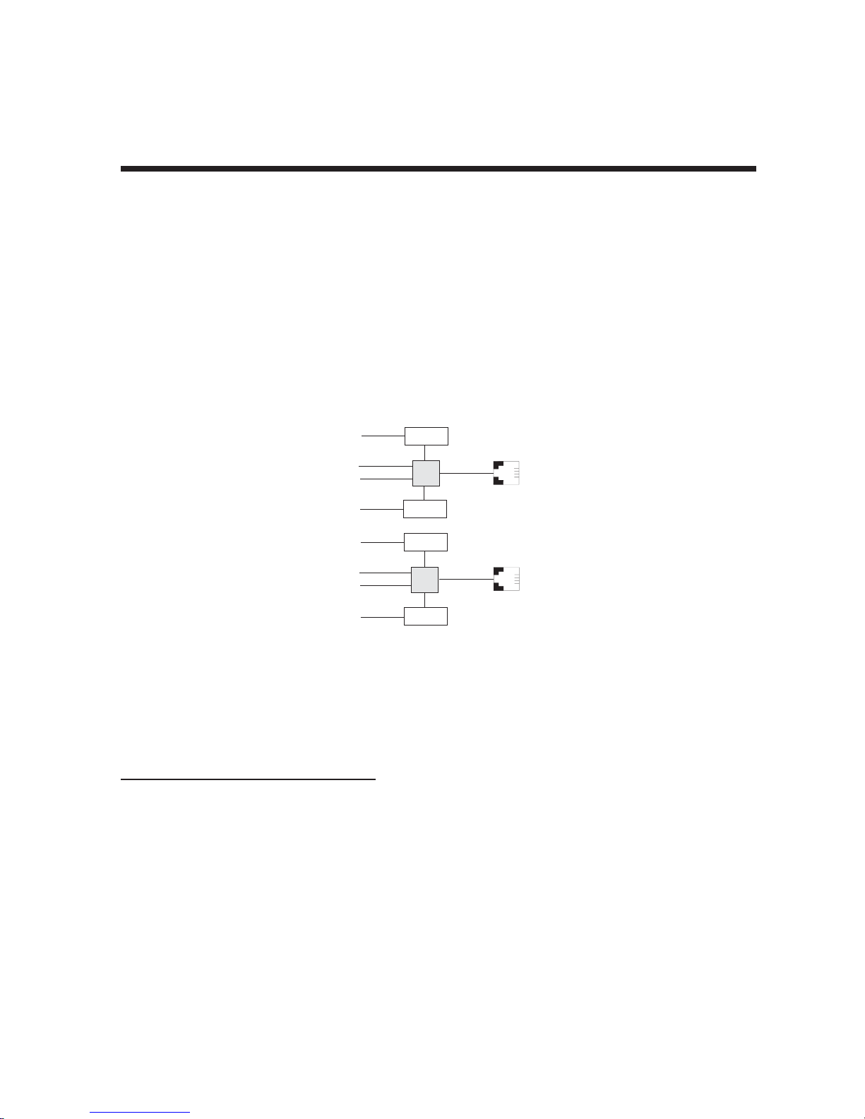
From the perspective of the server PC, the ISIHP-2S/2U (or ISIHI-2S/2U) is an eight-port serial card with eight
devices permanently attached to the serial ports (Figure 1-1).
Com Ports
5
1
2
6
7
3
4
8
Modem
TA
Modem
Modem
TA
Modem
ISDN
RJ-45 jack
3456
RJ-45 jack
3456
Line 1
Line 2
Figure 1-1. Modems and Terminal Adapters
of ISIHP-2S/2U and ISIHI-2S/2U.
The first four ports are the two terminal adapters, each of which appear as two ports. The remaining four ports
are the four central site modems. The following table summarizes the correlation of ports and devices.
Table 2: 2S/2U Ports and Devices
2S/2U Device ISDN Line
Port # Number
1TA1
2TA1
3TA2
4TA2
5 Modem 1
6 Modem 1
7 Modem 2
8 Modem 2
8
Chapter 1 - Introduction
1.1.2 ISIHP-4S/4U Serial Card
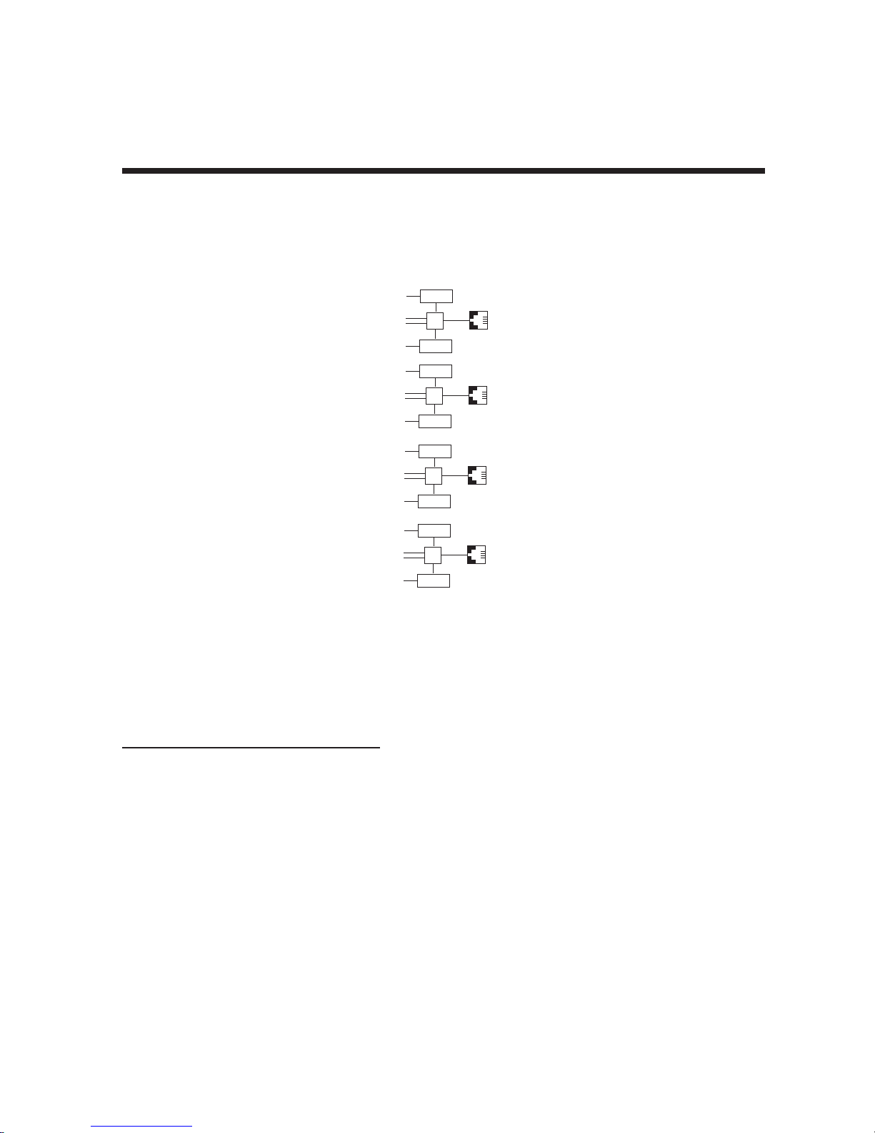
From the perspective of the server PC, the ISIHP-4S/4U is an sixteen-port serial card with sixteen devices
permanently attached to the serial ports (Figure 1-2).
9
Modem
1
2
Modem
10
11
Modem
3
4
Modem
12
13
Modem
5
6
Modem
14
15
Modem
7
8
Modem
16
RJ-45 Jack
TA
TA
TA
TA
3456
RJ-45 Jack
3456
RJ-45 Jack
3456
RJ-45 Jack
3456
Figure 1-2. Modems and Terminal Adapters
of ISIHP-4S/4U (for ISIHP-4SD, no modems are present)
The first eight ports are the four terminal adapters, each of which appear as two ports. The remaining eight
ports are the eight central site modems. Table 3 summarizes the correlation of ports and devices. The ISIHP4SD contains terminal adapters only; no modems are present.
Table 3: 4S/4U Ports and Devices
4S/4U Device ISDN Line
Port # Number
1TA1
2TA1
3TA2
4TA2
5TA3
6TA3
7TA4
8TA4
9 Modem 1
10 Modem 1
11 Modem 2
12 Modem 2
13 Modem 3
14 Modem 3
15 Modem 4
16 Modem 4
9

Chapter 1 - Introduction
1.2 Peripiheral Component Interconnect (PCI) for ISIHP Cards
First developed by companies such as IntelTM, AT&TTM and Digital Equipment CorporationTM, the Peripheral
Component Interconnect (PCI) bus used by your ISIHP card provides high performance and is easy to use.
Because PCI devices contain registers with the device information required for configuration, full auto
configuration of PCI Local Bus add-in boards and components is supported. Performance factors include a
bus data path of 32 bits, and clock speeds of 33 MHz.
1.3 Communication Protocols for ISIHP Por ts
Ports on the ISIHP card can be associated with different protocols, as follows:
Auto-Protocol Terminal adapter automatically detects and switches to use the protocol of the
client terminal adapter.
Auto-Protocol Callback Same as Auto-Protocol except that it causes the host terminal-adapter to dial
back with the same protocol with which the client dialed in.
Central Site Modem The digitally terminated V.90 modems built into ISIHx series cards (except the
4SD model). For the ISIHP-2S/2U, the last four modems should be designated
as Central-Site modems; for the ISIHP-4S/4U, the last eight modems should be
designated as Central-Site modems. (See Port/Device table on previous
page.)
PPP async (Point-to Point Protocol, asynchronous) Protocol allowing computers a dial-up
connection to the Internet. PPP includes error detection, data compression
and other improvements over Serial Line Internet Protocol (SLIP) connections.
V.120 Terminal rate adaptation protocols. These apply to ISDN B-channels when
using a V interface.
X.75 An international standard that allows X.25 packet-switched networks to
communicate with each other. X.75 is a gateway protocol for interconnection
of X.25 public networks.
10

Chapter 2 - Hardware Installation

Chapter 2 - Hardware Installation
2.1 Introduction
This section describes how to install the ISIHx server card into the expansion slot in your PC.
2.2 Computer Requirements
• Pentium-based PC or compatible (PCI bus required for ISIHP; ISA required for ISIHI)
• Microsoft Windows 2000, Windows 98, Windows Me, Windows NT versions 3.51 and 4.0, SCO Open
Server version 5.0, Novell NetWare, or Linux
• CD-ROM drive, floppy disk drive (for use in cases where drivers are downloaded from web site)
• 800 blocks of hard disk space for UNIX, 100K bytes for Windows NT, 50K bytes for Novell
2.3 Shipping Contents
• ISIHx card
• RJ-45 ISDN cords (1 for ISIHP-1S; 2 for ISIHx-2S/2U; 4 for ISIHP-4S/4U/4SD)
• ISI Product Family CD-ROM (containing drivers, utilities, & documentation)
• Quick Start Guide
2.4 Safety W arnings
1. Never install telephone wiring during a lightning storm.
2. Never install telephone jacks in wet locations unless the jacks are specifically designed for wet locations.
3. This product is to be used with UL and cUL listed computers.
4. Never touch uninsulated telephone wires or terminals unless the telephone line has been disconnected at
the network interface.
5. Use caution when installing or modifying telephone lines.
6. Avoid using a telephone (other than cordless type) during an electrical storm. There may be a remote risk
of electrical shock from lightning.
7. Do not use the telephone to report a gas leak in the vicinity of that leak.
8. To reduce the risk of fire, use only No. 26 AWG or larger Telecommunication line Cord.
12
Chapter 2 - Hardware Installation
2.5 Hardware Installation Procedure
1. Before handling the ISIHP card, discharge any static in your body by touching a piece of grounded metal
such as the computer chassis.
2. Carefully remove the ISIHP card from its antistatic bag, handling it only by the mounting bracket and
edges. Do not touch the gold-plated connectors along the bottom edge. (You may want to save packaging
for possible future use.)
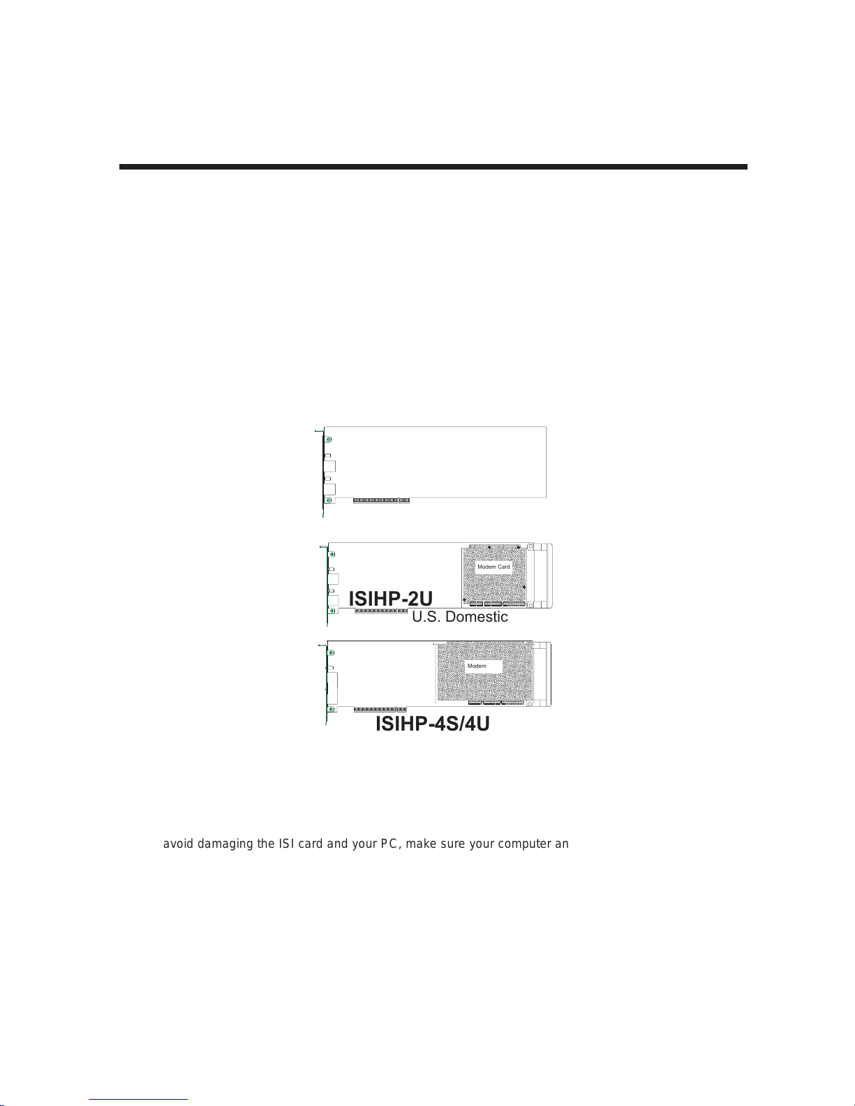
3. Visually inspect the ISIHP-2S/2U/4S/4U/4SD. If you have any concerns about the condition of your ISI
card, call Technical Support at (800) 972-2439.
Intelligent Serial Interface
Hybrid (ISDN/POTS) Cards
Side View
(
ISIHP-2S
International
)
Modem Card
ISIHP-2U
U.S. Domestic
Modem Card
ISIHP-4S/4U
Figure 2-1. ISIHP Cards Side View
4. To avoid damaging the ISI card and your PC, make sure your computer and any peripheral equipment
connected to it are turned off. The ISIHP can be installed in a Pentium equivalent PCI bus computer; the
ISIHI can be installed into a Pentium equivalent computer with ISA slots.
5. Remove the cover of your computer as instructed in your computer’s documentation.
6. Locate the unused expansion slot you will be using for your ISI card and remove the slot cover according
to instructions in your computer’s documentation.
13
Chapter 2 - Hardware Installation
7. Install the ISI card in the selected expansion slot in the same manner as any other add-on card according
to your computer’s documentation.
8. Fasten retaining bracket to computer chassis and replace the cover.
9. Connect the ISI to your ISDN telephone wall jack(s) with the provided modular telephone cable.
10. Turn on power to the computer. Now you are ready to install software.
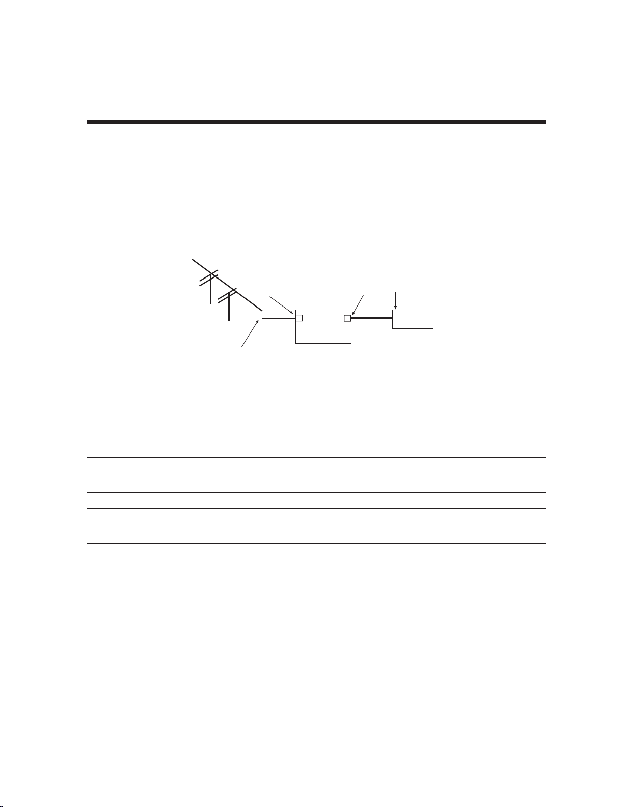
U Interface
ISDN line enters
building
NT1
Device
S Interface
S/T Interface
ISIHP
-2S
Figure 2-2. ISDN Interfaces at Customer Premises
Note: The ISIHP and ISIHI communicate over ISDN lines. If you don’t have a standard modular jack near your
computer, you should install one or have one installed by your telephone company. In the US, installation kits
and adapters are available wherever telephones are sold.
Note: If S/T-interface ISDN network connection cable is used, the ISDN phone cord should be connected
between the ISDN network connection cable and the NT1 device. If the S/T-interface model (ISIHP-2S, -4S, or
4SD, or ISIHI-2S) is used, then the S/T-interface must be connected to the S-interface on the NT1 device.
14
Chapter 2 - Hardware Installation
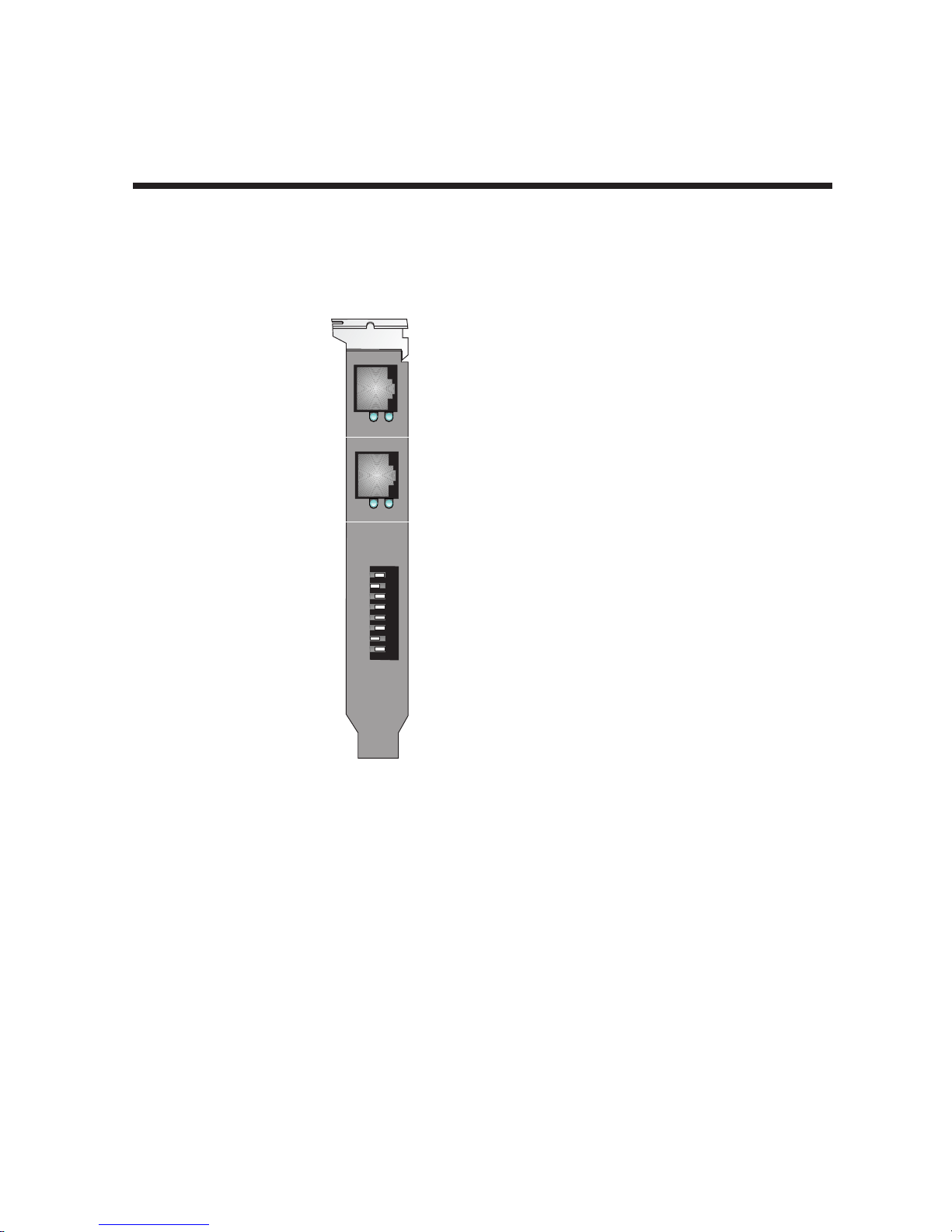
2.6 LED Indicators
The mounting brackets for the various ISI cards are similar, but the LEDs are labeled differently. Diagrams for
each bracket along with descriptions of the LED indicators are shown in Figures 2-3 thru 2-7.
ISIHP-4U LEDs (one LED per BRI)
Flashes between OFF and RED to
indicate that neither SPID for that
ISDN line has been verified.
1
3
LINE 1
2
4
Line 1
Line 2
Line 3
Flashes between RED and GREEN
to indicate that one SPID is correct.
A solid GREEN display indicates
that both SPIDs are correct.
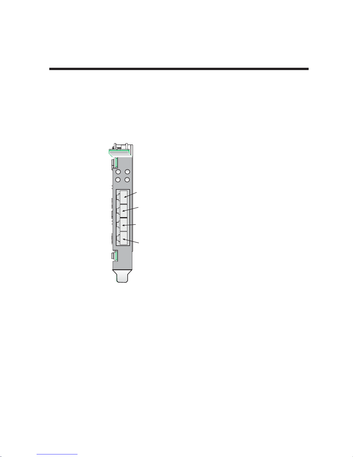
ISIHP-4S/4SD LEDs (one LED per BRI)
Solid GREEN indicates normal operation.
Flashes between RED and GREEN
to indicate that the device has been reset.
Line 4
Figure 2-3. ISIHP-4U, 4S/4SD LEDs
15
D
P
LINE 1
D
P
LINE 2
Chapter 2 - Hardware Installation
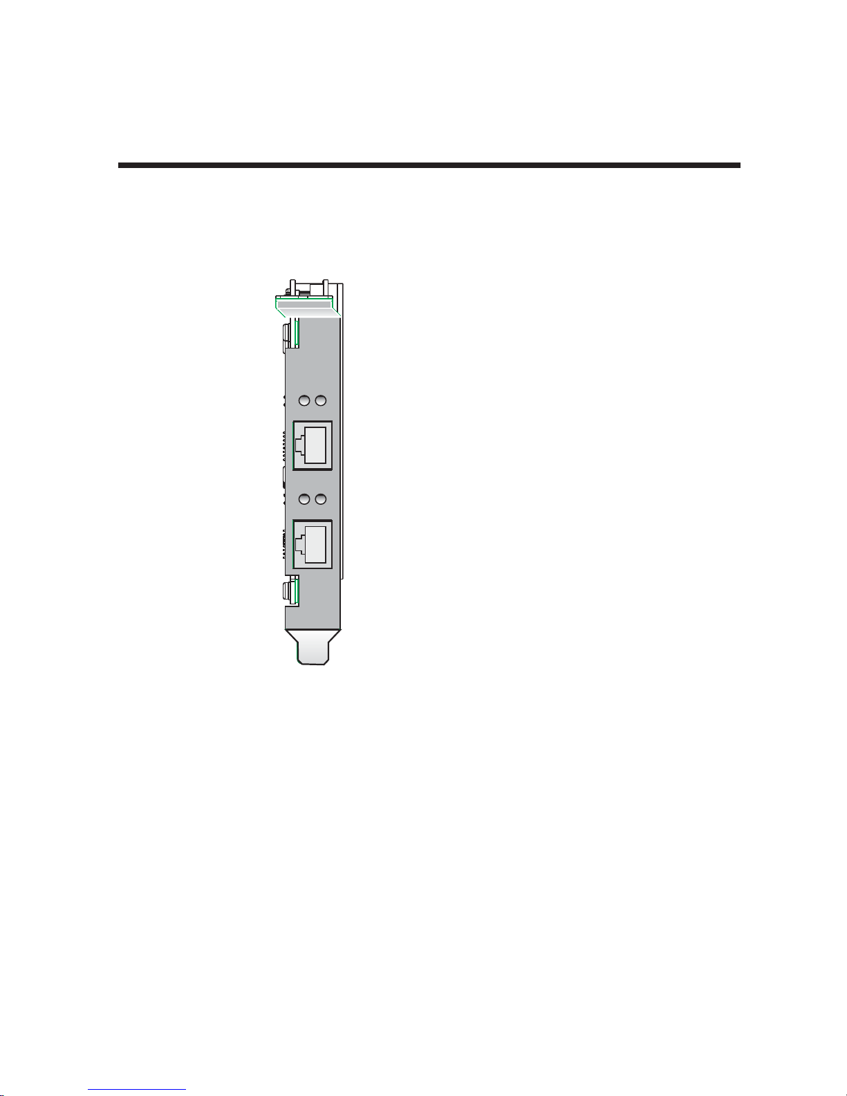
ISIHP-2U LED Indicators
P LED Indicator
Indicates U interface status connection.
Controlled by NT-1, which converts S/T
interface (4-wire ISDN) to U interface
(2-wire ISDN).
When U interface and S/T interface are NOT
active, LED remains off.
Flashes 8 times/second (8 Hz)U interface
is attempting to activate.
Flashes once/second (1 Hz)U interface is
active; S/T interface is not fully active.
Lit, not flashingBoth U and S/T interfaces
are active.
D LED Indicator
Lights when the ISIHP-2U is turned on.
Flashes until SPIDs are verified with the
central office switch; then remains lit without
flashing.
Indicates data link layer status.
Figure 2-4. ISIHP-2U LEDs
16
B2
s
B1
LINE 1
D
P
LINE 2
Chapter 2 - Hardware Installation
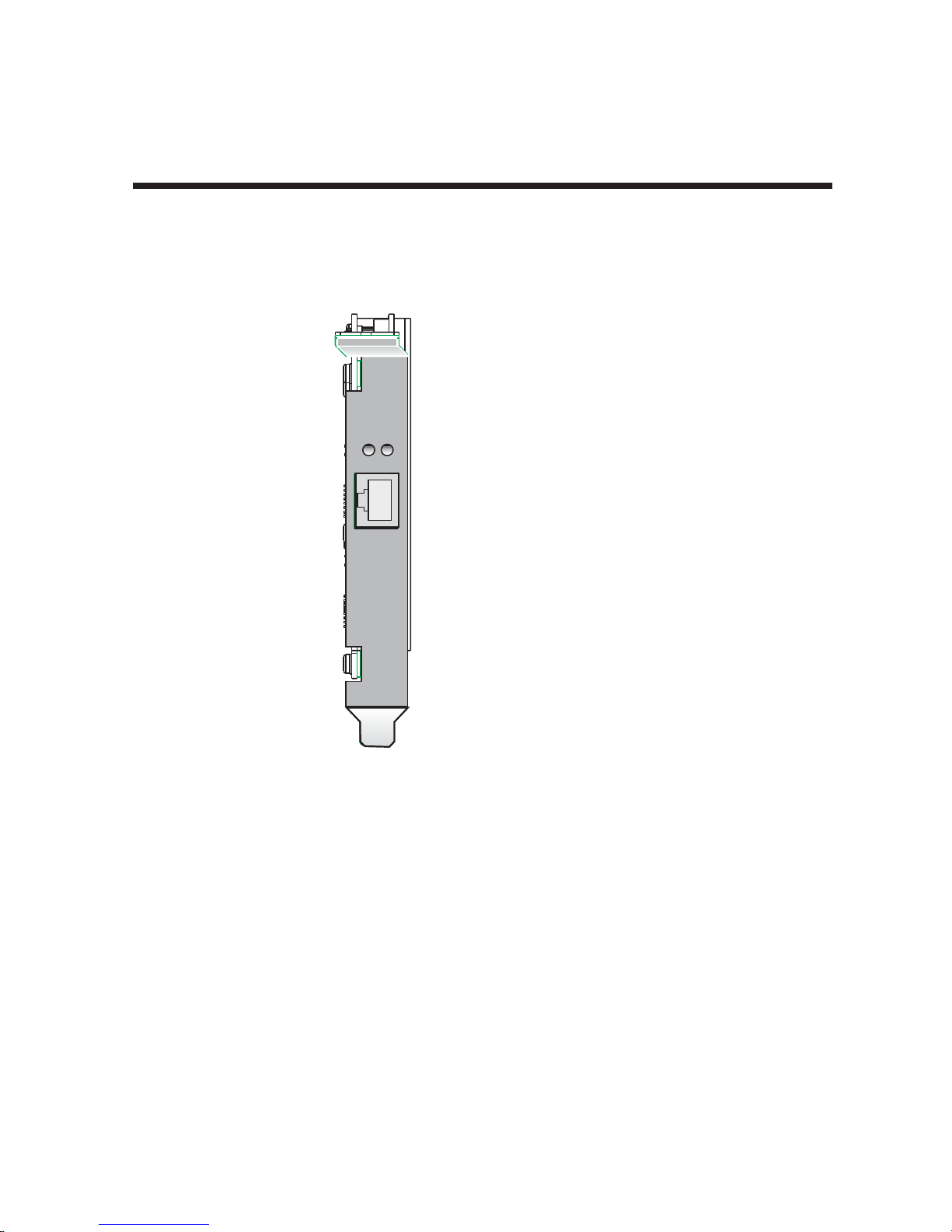
ISIHP-1S LED Indicator
B1 LED Indicator
When lit, indicates active
or voice connection on
B-channel 1.
B2 LED Indicator
When lit, indicates active
or voice connection on
B-channel 2.
Figure 2-5. ISIHP-1S LEDs
17
LINE 1
B1 B 2
LINE 2
B1 B 2
I
O
A
D
D
R
Chapter 2 - Hardware Installation
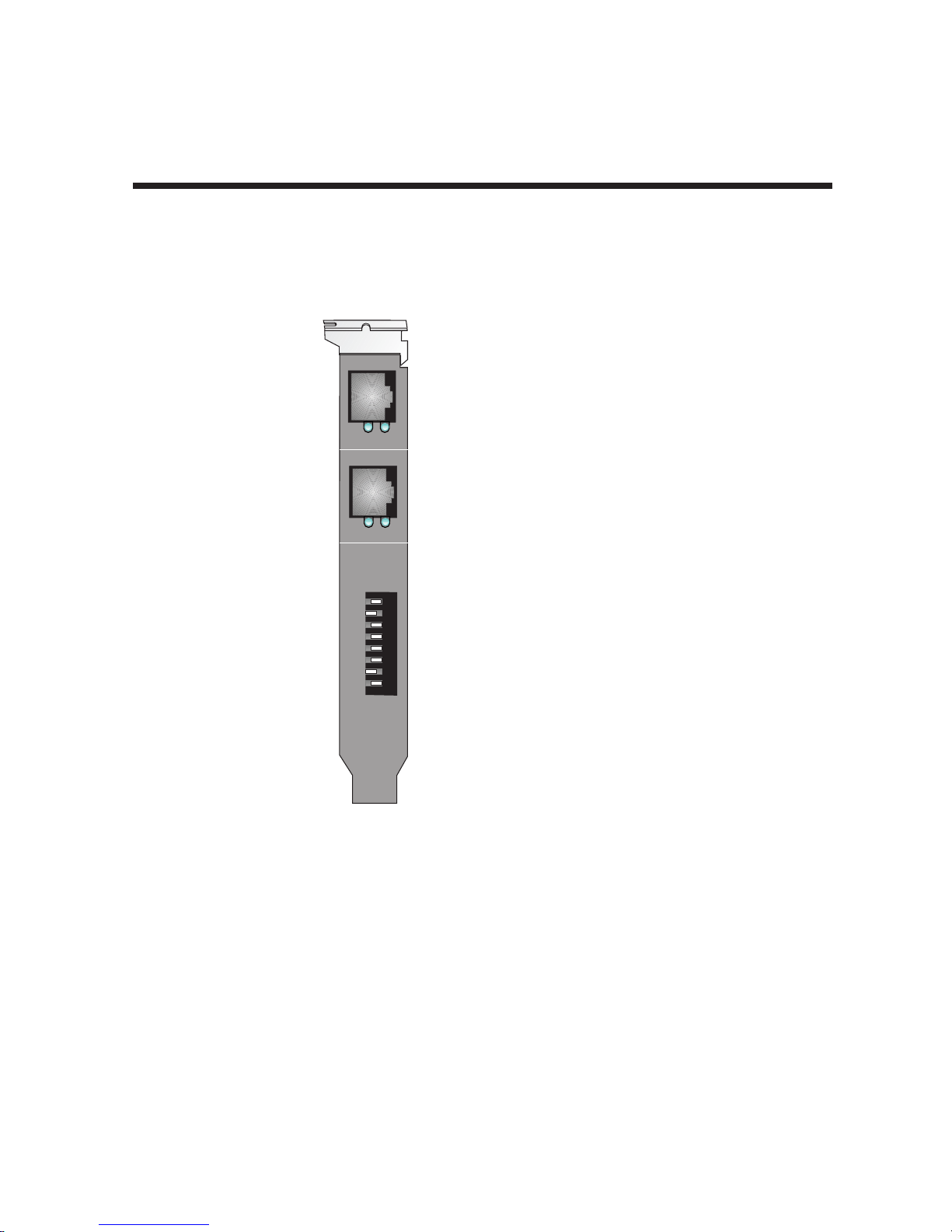
ISIHI-2S LED Indicators
B1 LED Indicator
When lit, indicates active or
voice connection on B-channel 1.
B2 LED Indicator
When lit, indicates active or
voice connection on B-channel 2.
The settings of the multiple DIP switch
unit on the mounting bracket determine
the base Input/Output address for the
ISIHI-2S/2U card. Input/Output
(I/O) addresses are used to route
information to and from the card.
Figure 2-6. ISIHI-2S LEDs
18
LINE 1
LINE 2
I
O
A
D
D
R
PD
PD
8
7
6
5
4
3
2
1
ISIHI-2U LED Indicators
P LED Indicator
Indicates U interface status connection.
Controlled by NT-1, which converts
S/T interface (4-wire ISDN) to
U interface (2-wire ISDN).
When U interface and S/T interface
are NOT active, LED remains off.
Flashes 8 times/second (8 Hz)
U interface is attempting to activate.
Flashes once/second (1 Hz)
U interface is active; S/T interface is
not fully active.
Lit, not flashingBoth U and
S/T interfaces are active.
D LED Indicator
Lights when the ISIHI-2U is
turned on.
Flashes until SPIDs are verified
with the central office switch;
then remains lit without flashing.
Indicates data link layer status.
The settings of the multiple DIP switch
unit on the mounting bracket determine
the base Input/Output address for the
ISIHI-2S/2U card. Input/Output
(I/O) addresses are used to route
information to and from the card.
Chapter 2 - Hardware Installation
Figure 2-7. ISIHI-2U LEDs
19

Chapter 3 - Software Installation

Chapter 3 - Software Installation
3.1 Introduction
This chapter describes software/driver installation for the ISI cards when used in Windows 2000, Windows
NT4, Windows NT3.51, Novell, Linux, and SCO Open Server 5. We also describe installation of MultiTech’s
Management Software for use with ISI cards under Windows 2000.
3.2 Installing ISIHI Software for Windows 2000
1. Turn off the PC.
2. The ISIHI card must already be installed in an ISA expansion slot in the PC. If it is not, follow the PC
manufacturer's instructions concerning installation of expansion cards.
Note: Observe standard precautions regarding electrostatic discharge (ESD) when handling the ISIHI board.
During installation, handle the ISIHI circuit card by its edges and keep one hand in contact with the PC
chassis.
3. Set the Base I/O Address and the Interrupt Request (IRQ) values per the table below. The I/O Address
DIP Switch is on the end plate of the ISIHI; the IRQ Jumper Block is on the component side of the circuit
card, lower middle area.
Table 4: Recommended Base I/O Address and IRQ Values
ISIHI-2S/2U Base I/O IRQ
Initial 8 port board 210h 10
First 8 port upgrade 220h 11
Second 8 port upgrade 230h 12
Third 8 port upgrade 240h 15
Address
4. Turn on the PC and start Windows 2000.
5. Insert the ISI installation CD into the CD drive in your computer.
6. Go to
7. At the Choose a Hardware Task screen, select "Add/Troubleshoot a device." Click Next.
8. At the Choose a Hardware Device screen, select "Add a new device." Click Next.
9. At the Find New Hardware screen, select "No, I want to select the hardware from a list." Click Next.
10. At the Hardware Type screen, select "Multi-port serial adapters." Click Next.
11. At the Select a Device Driver screen, click on Have Disk.
12. At the Install from Disk screen, enter the path of the driver files (i.e., the file directory location, in most
13. In the Models list, highlight "Multi-Tech ISI4608-ISA 8 Port Serial Card." A comment screen appears
Start | Settings | Control Panel | Add/Remove Hardware
cases on CD-ROM). Click OK.
indicating that the Base I/O Address and IRQ must be specified for the ISIHI card. Click OK.
. Click Next.
21

14. The Add New Hardware Wizard Properties screen appears.
a. In the Resource Settings field, select "Input/Output Range" and click on Change Setting.
The Edit Input/Output Range screen appears.
Select the value that matches the Base I/O Address value that you have already set on
the ISIHI board in Step 2. Click OK.
b. In the Resource Settings field, select "Interrupt Request" and click on Change Setting.
The Edit Interrupt Request screen appears.
Select the value that matches the IRQ value that you have already set on the ISIHI
board in Step 2. Click OK. At the Resources tab, click OK again.
15. At the Start Hardware Installation screen, click Next.
16. A completion screen appears. Click Finish.
17. You will be prompted to restart your computer. Click Yes.
Chapter 3 - Software Installation
22

Chapter 3 - Software Installation
3.3 Installing ISIHP Software for Win 2000
Note: A series of ‘installation wizard’ screens will appear repeatedly during this procedure (step 12). This is
not an error. Do not discontinue the procedure when the ‘installation wizard’ screens repeatedly appear.
1. Shut down Windows 2000 and turn off the PC.
2. Install the ISIHP can in an available PCI expansion slot in the PC. Follow the PC manufacturer's
instructions concerning installation of expansion cards.
Note: Observe standard precautions regarding electrostatic discharge (ESD) when handling the ISIHI board.
During installation, handle the ISIHI circuit card by its edges and keep one hand in contact with the PC
chassis.
3. Turn on the PC and start Windows 2000.
4. Insert the ISI driver CD-ROM into the CD-ROM drive. Windows 2000 will detect the ISIHP card. The
Found New Hardware Wizard- Welcome screen will appear. Click Next.
5. The Install Hardware Device Drivers screen appears. Select "Search for a suitable driver ..." and click
Next.
6. The Locate Driver Files screen appears (Windows 2000 is seeking the driver for the ISIHP card). Select
“CD-ROM drives” and click Next.
7. The Driver File Search Results screen appears. Click Next. A progress screen will appear briefly while
files are being copied.
8. A completion screen will appear. Click Finish.
9. Immediately after the ISI driver installation has been completed, another Found New Hardware screen will
appear briefly indicating that the “MultiTech ISI Port” has been detected.
10. A second sequence of ‘installation wizard’ screens appears. This sequence of screens deals with the
setting up of ISI ports. The first screen in this sequence is the Found New Hardware Wizard -- Welcome
screen.
11. The Found New Hardware -- MultiTech ISI Port screen will appear once for each modem and terminal
adapter on the ISIHP card:
• 16 times for the ISIHP-4S/4U/4SD (only 8 devices can be installed on the 4SD)
• 8 times for the ISIHP-2S/2U/1S (only 4 devices can be installed for the ISIHP-1S)
12. The Install Hardware Device Drivers screen appears. Select “Search for a suitable driver ... “. Click Next.
13. The Locate Driver Files screen appears (Windows 2000 is seeking the ISI Port device driver). Select “CD-
ROM drives” and click Next.
14. The Driver Files Search Results screen will indicate that the “isiport.inf” file has been found on the CDROM. Click Next.
15. A completion screen will appear. It will indicate that the first “MultiTech ISI Port” has been set up
successfully. Click Finish.
The Found New Hardware -- MultiTech ISI Port screen will appear many times after the ISI driver has
been located. On this screen, the messages “Found New Hardware” and “Installing ...” will appear
alternately. Repetition of these screen sequences is normal and is not an error.
16. Driver installation for the ISIHP card is complete.
23

Chapter 3 - Software Installation
3.4 ISIHx for Win 2000: Installing ISI Management Software (server
OSs only)
If you are using a Windows 2000 Server operating system ("Server" or "Advanced Server"), you must decide
whether you want to use the MultiTech ISI Management Software in conjunction with your ISIHx board. The
ISI Management Software is shipped with the ISI card.
1. Turn on your computer and start Windows 2000.
2. Insert the CD-ROM containing the ISI Management Software into your CD-ROM drive.
3. Go to
4. The ISI Management setup screen appears. At the Welcome screen, click Next.
5. A progress screen appears while files are copied. If the Error Creating WWW Server message appears, it
6. A completion screen appears. Select "Yes, I want to restart my computer now" and click Finish.
7. After the computer has restarted, the installation of the driver and of the ISI Management Software will be
Start | Run
would be
may indicate that there was an attempt to install the ISI Management Software on a client version of
Windows 2000. (The ISI Management Software can be installed only in the
Windows 2000 Advanced Server
complete.
. In the Run window, enter the file path of the ISI Management software. Typically, this
E:\SERVCARD\UTILITY\MGMT\SETUP.EXE
operating systems.)
. Click OK.
Windows 2000 Server
and
24

Chapter 3 - Software Installation
3.5 ISIHx for Windows 2000: Installing TAs and Modems
to COM Ports
Installation of Windows 2000 driver software must be completed before you can install the terminal adapters
and modems of the ISIHx card.
1. Go to
2. The Location Information screen appears. Enter the appropriate area code and access number. Click OK.
3. At the Phone and Modem Options screen, click on the Modems tab and click Add.
4. At the Install New Modem screen, click on "Don't detect my modem ... " and click Next.
5. If the software driver CD-ROM (or other media, in cases of using drivers downloaded from the MultiTech
6. If you are installing an ISIHP-1S card, go to step 25 for special instructions and then return to step 7.
Installing Terminal Adapters to COM Ports.
7. The Add/Remove Hardware Wizard screen will appear. Click “Have Disk ... .”
8. The Install from Disk screen will appear. Type or browse for the file path of the terminal adapter software
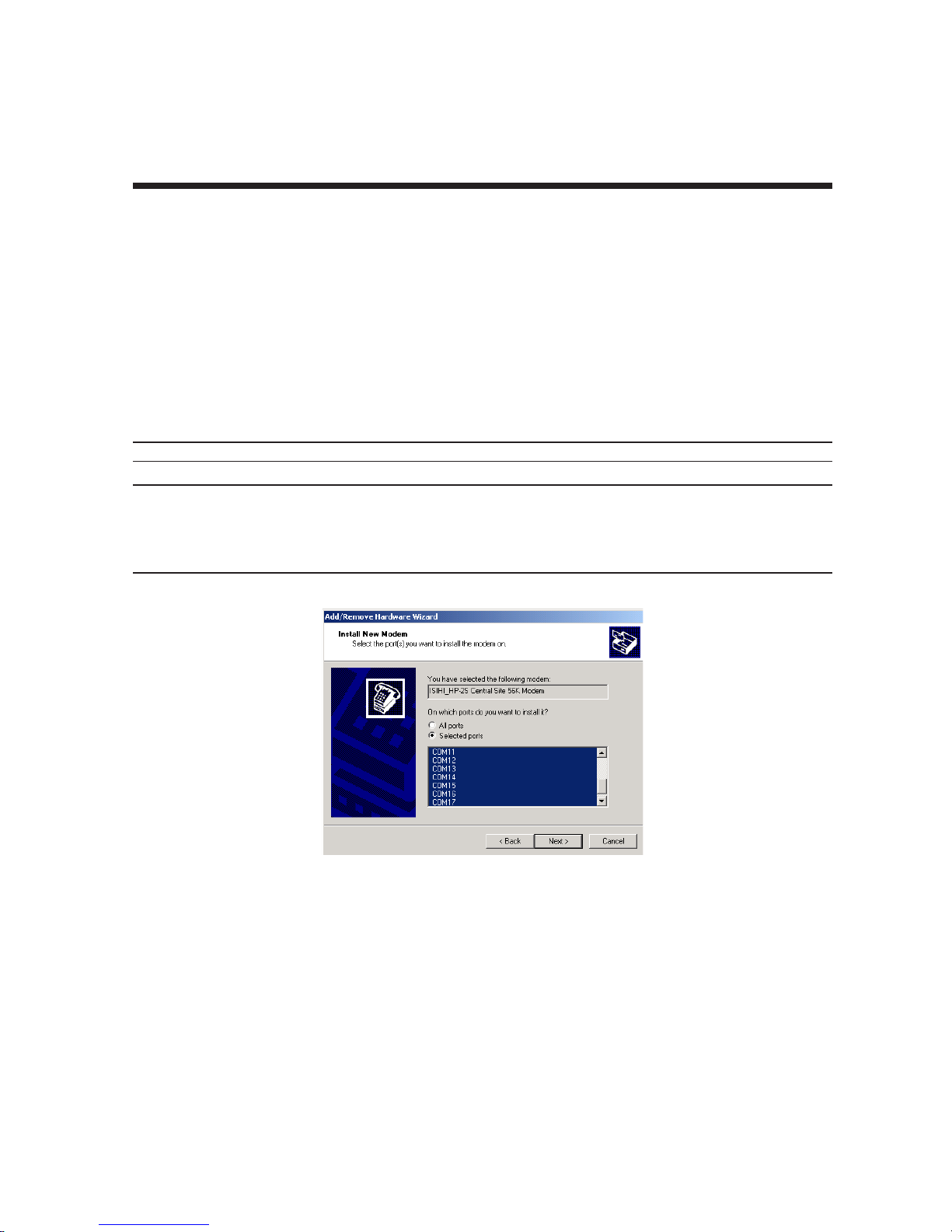
9. The Install New Modem screen appears. Highlight the terminal adapter protocol to be used. Click Next.
10. The ‘Install New Modem - Port List’ screen will appear.
Start | Settings | Control Panel | Phone and Modem Options
web site) is not already in the appropriate disk drive in the PC, insert it now.
Otherwise go directly to step 7.
(for example,
E:\servcard\drivers\win2000
). Click OK.
.
11. Highlight the COM ports on which you want terminal adapters to be installed. You must allocate 8 ports
for the ISIHP-4S/4U/4SD, or 4 ports for the ISIHP-2S/2U/1S, or 4 ports for the ISIHI-2S/2U. Click Next.
Note: The ISIHP-1S will only support two modem ports, but it is necessary to allocate four ports temporarily
during installation. The allocated-but-unused ports can be used for a different purpose after installation is
complete.
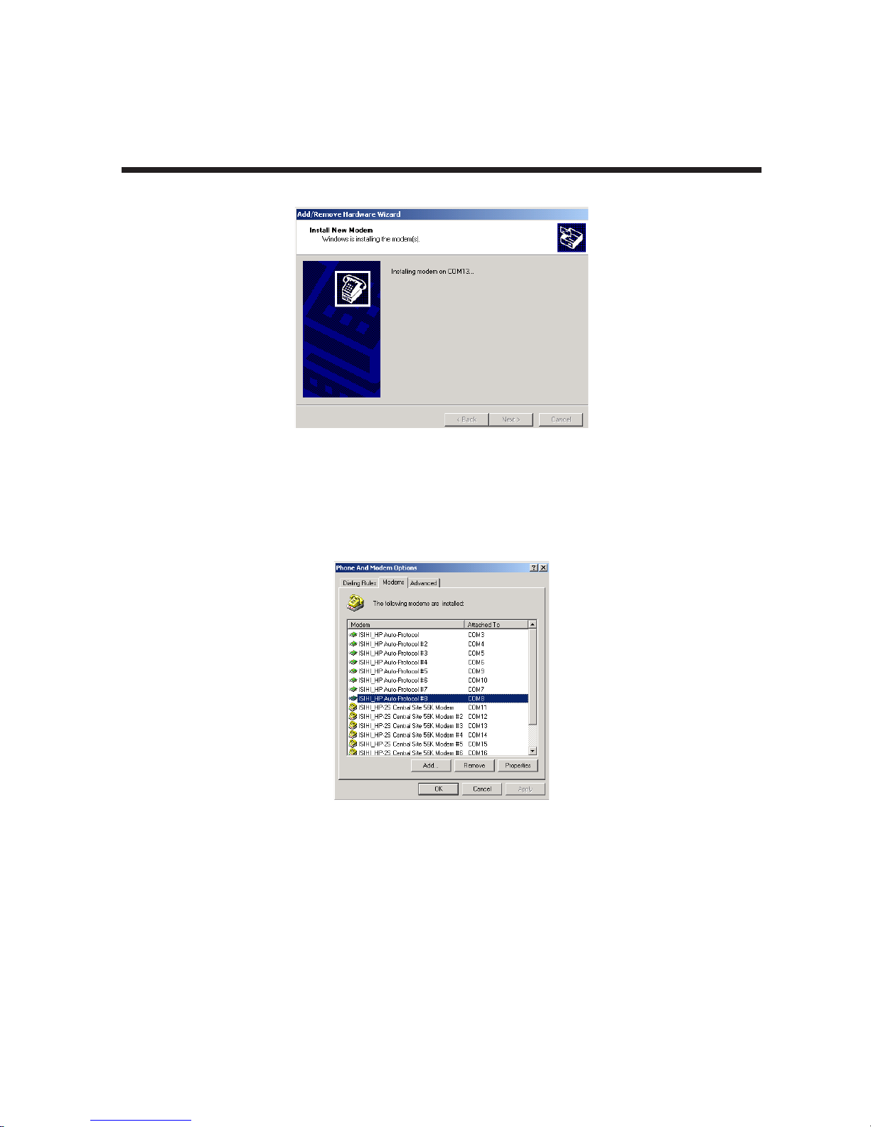
12. A progress screen will appear as TA installation begins. As TAs are installed to the specified COM ports,
a separate screen will appear denoting the process for each COM port.
25

Chapter 3 - Software Installation
13. A completion screen will appear. Click Finish.
14. The Phone and Modems Options screen (Modems tab) will reappear and display the TAs that have just
been assigned to COM ports.
Note: If you are installing a ISIHP-4SD, installation is now complete. (The 4SD has no modems).
Installing modems to COM Ports (not applicable to -4SD):
15. At the Phone and Modems Options screen (Modems tab), click Add.
26
Chapter 3 - Software Installation
16. The Install New Modems screen will appear. Select “Don’t detect my modem ....”. Click Next.
17. A screen listing modem manufacturers and models will appear. Click “Have Disk ....”
18. The Install from Disk screen will appear. Type or browse for the file path of the modem software (for
example,
19. The Install New Modem screen will show a list of MultiTech modem and terminal adapter drivers. Select
the modem type that fits the model of your specific server card.
E:\servcard\drivers\win2000
). Click OK.
• For 1S/2S/4S models, select “ISIHI_HP-2S Central Site 56K Modem". Click Next
• For 2U/4U models, select “ISIHI_HP-2U Central Site 56K Modem". Click Next.
20. The Install New Modem port list screen will appear. Highlight the COM ports on which you want modems
to be installed. You must allocate 8 ports for the ISIHP-4S/4U, or 4 ports for the ISIHP-2S/2U/1S, or 4
ports for the ISIHI-2S/2U. Click Next.
Note: The ISIHP-1S supports only two modems, but you must designate 4 ports during installation.
Note: The COM port numbers used must allow for 4 terminal adapter ports, even though 2 terminal adapter
ports will remain unused. For example, if you allocated COM3, COM4, COM5, and COM6 to terminal adapters
for the ISIHP-1S, you could allocate COM7, COM8, COM9, and COM10 to modems for the ISIHP-1S. COM5,
COM6, COM9, and COM10 would be unused by the ISIHP-1S and so could be allocated to a different function
after installation of the ISIHP-1S is complete.
21. A progress screen will appear as modem installation begins.
22. Screens denoting the installation of modems to specific COM ports will appear.
27
Chapter 3 - Software Installation
23. A completion screen will appear. Click Finish.
24. The Phone and Modems Options screen (Modems tab) will reappear and display the modems that have
just been assigned to COM ports. Installation of terminal adapters and modems to COM ports is now
complete.
28
Chapter 3 - Software Installation
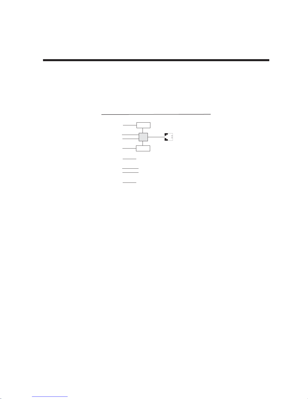
25. For the ISIHP-1S card only. The ISIHP-1S is a scaled-back revision of the ISIHP-2S card meant for lowdensity applications where hybrid flexibility (having TAs and modems on the same card) is advantageous.
The diagram below describes the design differences between the ISIHP-1S and ISIHP-2S. It also
summarizes how the ISIHP-1S must be treated during installation.
ISIHP -- Differences between 1S and 2S versions,
especially COM port assignments
Com Ports
5
1
2
6
7
3
4
8
When installing ISIHP-1S software:
(a) treat ISIHP-1S as an 8-port card;
(b) assign first 2 ports as terminal adapters (TAs);
(c) skip two port numbers;
(d) assign next 2 ports as analog modems.
(e) Other devices can use port numbers
that were skipped by the ISIHP-1S.
Modem
TA
Modem
}
ISDN
RJ-45 jack
3456
These ports
are unused
on the ISIHP-1S.
Line 1
29

3.5 Remove ISIHx Driver (Windows 2000)
Chapter 3 - Software Installation
1. Go to
2. Click on Add/Remove Hardware. Click Next.
3. Click on “Uninstall/Unplug a device” and click Next.
4. In the subsequent screen, click on “Uninstall a device” and click Next.
5. At the Add/Remove Hardware Wizard screen, highlight the ISI driver file for the specific server card that
6. When you are asked to confirm removal, click on the Yes radio button and click Next.
7. Click Finish. You can remove the driver for only one ISIHx card at a time.
Start | Settings | Control Panel.
you intend to remove. Click Next.
3.6 ISIHx Software Installation Procedure for
Windows NT 3.51/4.0
1. Turn off the PC.
2. The ISIHx card must be installed in an expansion slot in the PC. If not, follow the PC manufacturer's
instructions concerning installation of expansion cards.
• For ISIHP cards. Install the ISIHP card in an available PCI expansion slot in the computer.
• For ISIHI cards. Install the ISIHI card in an available ISA expansion slot in the computer. Set the Base
I/O Address and the Interrupt Request (IRQ) values per the table below. The I/O Address DIP Switch is
on the end plate of the ISIHI; the IRQ Jumper Block is on the component side of the circuit card, lower
middle area.
Note: Observe standard precautions regarding electrostatic discharge (ESD) when handling the ISIHx board.
During installation, handle the ISIHx circuit card by its edges and keep one hand in contact with the PC
chassis.
Table 5: Recommended Base I/O Address and IRQ Values
ISIHI-2S/2U Base I/O IRQ
Initial 8 port board 210h 10
First 8 port upgrade 220h 11
Second 8 port upgrade 230h 12
Third 8 port upgrade 240h 15
3. Turn on the PC and start Windows NT4.0.
4. Insert the driver CD-ROM into the CD-ROM drive.
5. Click
6. The Select Network Adapter dialog box appears. Click Have Disk.
7. The Insert Disk dialog box appears. Type or browse for the path (file directory location) of the Windows
Start | Settings | Control Panel | Network | Adapters
NT driver (for example,
Address
. Then click Add.
E:\SERVCARD\DRIVERS\WINNT\SETUP.EXE
). Click OK.
30
 Loading...