

Page 1

MultiModem ISI Hybrid Series
Models ISIHP-1S/2S/2U
ISIHP-4S/4U/4SD
and ISIHI-2S/2U
User Guide
Page 2

MultiModem ISI Hybrid Series User Guide
PN: S000328B
Copyright ©2004 by Multi-Tech Systems, Inc.
All rights reserved. This publication may not be reproduced, in whole or in part, without prior written permission from Multi-
Tech Systems, Inc.
Multi-Tech Systems, Inc. makes no representations or warranties with respect to the contents hereof and specifically
disclaims any implied warranties of merchantability or fitness for any particular purpose. Furthermore, Multi-Tech Systems,
Inc. reserves the right to revise this publication and to make changes from time to time in the content hereof without
obligation of Multi-Tech Systems, Inc. to notify any person or organization of such revisions or changes.
Revision Date Description
A 12/30/2003 Initial release of MultiModem ISI Hybrid Series User Manual on CD. This release removed
B 08/26/2004 Added AT Commands Chapter (Chapter 5).
Trademarks
MultiTech and the MultiTech logo are trademarks of Multi-Tech Systems, Inc.
All other trademarks are property of their respective companies.
Technical Support
France [email protected] +33 1-64 61 09 81
India [email protected] +91 124 6340778
U.K. [email protected] +44 118 959 7774
U.S., Canada [email protected] (800) 972-2439
Rest of World [email protected] +763 717-5863
V110 capability from product.
World Headquarters
Multi-Tech Systems, Inc.
2205 Woodale Drive
Mounds View, Minnesota 55112 U.S.A.
(763) 785-3500 or (800) 328-9717
U.S. FAX (763) 785-9874
Technical Support (800) 972-2439
www.multitech.com
Page 3

Contents
Chapter 1 - Introduction ....................................................................... 6
1.1 Introduction ............................................................................................. 7
1.1.1 ISIHP-2S/2U Serial Card .....................................................................8
1.1.2 ISIHP-4S/4U Serial Card .....................................................................9
1.2 Peripiheral Component Interconnect (PCI) for ISIHP Cards ................ 10
1.3 Communication Protocols for ISIHP Ports ........................................... 10
Chapter 2 - Hardware Installation ...................................................... 11
2.1 Introduction ........................................................................................... 12
2.2 Computer Requirements ...................................................................... 12
2.3 Shipping Contents ................................................................................ 12
2.4 Safety Warnings ................................................................................... 12
2.5 Hardware Installation Procedure .......................................................... 13
2.6 LED Indicators ...................................................................................... 15
Chapter 3 - Software Installation ....................................................... 20
3.1 Introduction ........................................................................................... 21
3.2 Installing ISIHI Software for Windows 2000 ......................................... 21
3.3 Installing ISIHP Software for Win 2000 ................................................ 23
3.4 ISIHx for Win 2000: Installing ISI Management Software (server OSs only) .. 24
3.5 ISIHx for Windows 2000: Installing TAs and Modems
to COM Ports........................................................................................ 25
3.5 Remove ISIHx Driver (Windows 2000) ................................................ 30
3.6 ISIHx Software Installation Procedure for
Windows NT 3.51/4.0 ........................................................................... 30
3.7 Installing ISIHx TAs & Modems to COM Ports in Windows NT ............ 32
3.8 Removing ISIHx Card and Driver in Windows NT 3.51/4.0 .................. 36
3.8.1 I/O Addresses and IRQ Codes ......................................................... 36
3.9 Configuring the Terminal Adapter ......................................................... 37
3.9.1 Introduction .......................................................................................37
3.9.2 North American Users ....................................................................... 37
3.9.3 International Users ............................................................................ 37
3.9.4 Optional Settings .............................................................................. 38
3.10 ISDN TA Configuration Utility ............................................................... 39
3.11 ConfigMenu Configuration Utility .......................................................... 41
3.11.1 ConfigMenu Menus ........................................................................... 41
3.12 Terminal Adapter AT Commands .......................................................... 42
Page 4

3.13 NetWare Driver Installation .................................................................. 42
3.13.1 Configuring Ports for NetWare Connect .......................................... 43
3.13.2 Removing the Driver (Novell) ............................................................ 43
3.14 SCO Open Server 5 Driver Installation ................................................ 43
3.14.1 Install from CD-ROM ......................................................................... 43
3.14.2 Format a Floppy Disk for SCO5 ........................................................ 44
3.14.3 Untar the Driver File and Copy Files to Floppy Disk ....................... 44
3.14.4 Install Driver from Floppy Disk ......................................................... 45
3.14.5 MultiTech Installation Script .............................................................46
3.14.7 Activating Ports in SCO Open Server 5............................................48
3.14.7 Removing the Driver (SCO Open Server 5) ...................................... 48
3.15 Linux Driver for Multi-Tech ISI Server Cards
(for PCI and ISA busses) ...................................................................... 49
3.15.1 LINUX: Pre-Installation Issues ..........................................................49
3.15.2 LINUX: Copying the Driver from the Media......................................49
3.15.3 LINUX: Copying & Untarring the Driver from CD-ROM ................... 49
3.15.4 LINUX: Copying & untarring the driver from a floppy ...................... 49
3.15.4.1 Copying the Driver from a Floppy ................................................. 50
3.15.5 LINUX: Driver Installation and Loading ............................................50
3.15.6 LINUX: Setting the baud rate ............................................................ 50
3.15.7 LINUX: Verifying the ports ................................................................ 51
3.15.8 LINUX: TTY Devices Created by the Drivers: ................................... 51
3.15.8.1 Devices Mapped for Hybrid Cards (ISIHI-xx and ISIHP-xx cards):52
3.15.9 LINUX: Dial-in Configuration ............................................................ 52
3.15.10 LINUX: PPP Setup ............................................................................. 52
3.15.10. Miscellaneous................................................................................. 53
3.15.11 Removing the ISI Driver (Linux) ........................................................ 53
3.16 RedHat Linux 6.2/7.0 RPM Drivers for ISI Server Cards
(PCI bus only)....................................................................................... 54
3.16.1 LINUX-RPM: Pre-Installation Issues ................................................ 54
3.16.2 LINUX-RPM: Copying the Driver from the Media ............................ 54
3.16.3 LINUX-RPM: Copying the driver from CD-ROM ..............................54
3.16.4 LINUX-RPM: Copying the Driver from a Floppy .............................. 54
13.16.4.1 Copying the Driver from a Floppy: ................................................55
3.16.5 LINUX-RPM: Verifying the ports .......................................................56
3.16.6 LINUX-RPM: TTY Devices Created by the Drivers .......................... 56
3.16.7 Devices Mapped for Hybrid Cards (ISIHP-xx cards): ...................... 57
3.16.8 LINUX-RPM -- Dial-in configuration: ................................................ 57
3.16.9 LINUX-RPM -- PPP setup: ................................................................57
3.16.9 Removing the ISI Driver (Linux-RPM) ............................................... 57
3.17 Warning About the Flashing of Terminal Adapter Ports ....................... 58
3.17.1 Firmware Update for ISIHx Terminal Adapters ................................58
Page 5

Chapter 4 - Warranty & Service ........................................................ 60
4.1 Multi-Tech Systems, Inc. Warranty & Repairs Policies ........................ 61
4.1.1 Warranty ............................................................................................ 61
4.1.2 U.S. and Canadian Customers ......................................................... 61
4.1.3 International Customers (outside U.S.A. and Canada) .................... 62
4.1.4 International Distributors ..................................................................62
4.2 Repairs ................................................................................................. 63
4.2.1 Repair Procedures for U.S. and Canadian Customers .................... 63
4.2.2 Repair Procedures for International Customers ..............................63
4.2.3 Repair Procedures for International Distributors ............................. 64
4.2.4 Replacement Parts............................................................................64
4.4 Technical Support ................................................................................. 64
4.5 Internet Site .......................................................................................... 64
Chapter 5 - AT Commands ................................................................. 65
Modem AT Commands .................................................................................. 66
Modes of Operation ....................................................................................... 66
Command Structure ...................................................................................... 66
Command Editing .......................................................................................... 67
Modem S-Registers ....................................................................................... 79
Modem Result Codes .................................................................................... 85
Terminal Adapter AT Commands ..................................................................87
General Information Commands ................................................................... 91
Analog (Modem) Call Commands ............................................................... 108
Terminal Adapter S-Registers ..................................................................... 110
Chapter 6 - Troubleshooting ............................................................ 122
Index................................................................................................. 126
Page 6

Chapter 1 - Introduction
Page 7

Chapter 1 - Introduction
1.1 Introduction
Welcome to Multi-Tech’s MultiModemISI Hybrid Series of ISDN BRI server cards. The series consists of eight
models, briefly described in the table below below.
Table 1: MultiModem ISI Hybrid Series Server Cards
Model Bus Lines ISDN Modem Term. Adap. Max. Con.
ISIHP-2S PCI 2 S 4 4 4
ISIHP-2U PCI 2 U 4 4 4
ISIHP-4S PCI 4 S 8 8 8
ISIHP-4U PCI 4 U 8 8 8
ISIHI-2S ISA 2 S 4 4 4
ISIHI-2U ISA 2 U 4 4 4
ISIHP-1S PCI 1 S 2 2 2
ISIHP-4SD PCI 4 S NONE 8 8
The 2S/2U and 4S/4U models are all multiport hybrid ISDN cards that can be plugged into a server expansion
slot (PCI or ISA, as listed) for applications that involve ISDN or modem calls over ISDN BRI lines. When the
ISI card is used with Remote Access Servers (RAS), remote users can call in using either modems or ISDN
terminal adapters (TAs). For V.90 modem calls, a 56kbps download speed can be achieved without the
expense of T1, E1, or ISDN PRI lines. S-models use the ISDN “S” interface; U-models use the ISDN “U”
interface.
This manual also describes the ISIHP-1S and the ISIHP-4SD cards. The ISIHP-1S is a revised version of the
ISIHP-2S card that has been altered to accept one ISDN Basic Rate Interface line rather than two. The ISIHP4SD is a serial interface card equipped with four terminal adapters only (no analog modems are present). The
ISIHP-4SD is otherwise like the ISIHP-4S/4U models.
Type Accepted Interface P orts Ports Sessions
The ISIHP-2S/2U contains two terminal adapters and four V.90/K56flex modems. The ISIHP-2S/2U uses two
ISDN BRI lines (each offering two B-channels) to connect to the telco and these connect to its two built-in
terminal adapters. In addition to handling ISDN calls, each terminal adapter can detect analog modem and fax
calls. When analog calls are detected, they are automatically connected to one of the four V.90 modems on
the ISIHP board. In this way, these hybrid cards can handle either ISDN calls or analog modem calls.
Although the ISIHP-2S/2U contains four ISDN TA ports and four analog modem ports, only four ports can be
active at any one time (because only four B-channels are present). See Figure 1-1. The ISIHI-2S/2U function
like the ISIHP-2S/2U units but have an ISA-type bus which requires manual setting of the I/O address and the
interrupt request (IRQ).
The ISIHP-4S/4U works like the ISIHP-2S/2U but contains four terminal adapters and eight V.90/K56flex
modems. The 4S and 4U models each accommodate four ISDN BRI lines. The configuration of modem and
TA ports for the 4S and 4U models is shown in Figure 1-2.
The ISIHP-4SD contains four terminal adapters only (the daughter card containing the eight modems is
absent). Since it accommodates four ISDN BRI lines (each offering two B-channels), it supports eight
independent digital data connections. Each terminal adapter appears as two ports to the server PC using the
ISI card. ISIHx cards also support dial-out applications via their modems or terminal adapters.
MultiTech’s ISI Management Software is designed to monitor data traffic and control the modems/TAs of ISIHx
server cards operating in the Windows 2000 Server and Advanced Server OSs. (See the ISI Management
Software User Guide, doc #88301450.)
7
Page 8
Chapter 1 - Introduction
1.1.1 ISIHP-2S/2U Serial Card
The ISIHP-2S/2U and ISIHI-2S/2U cards each offers eight RAS ports using two Basic Rate Interface (BRI)
ISDN lines; the ISIHP-4S/4U has 16 ports using four BRI ISDN lines. The eight ports of the 2S/2U models
allow a server to accept any combination of analog modem and digital ISDN calls, making a maximum of four
simultaneous independent data connections (sessions). For the ISIHP-4S/4U, its sixteen ports allow a server
to accept any combination of analog modem and digital ISDN calls, making a maximum of eight simultaneous
independent data connections. This arrangement gives the user the flexibility to customize the settings of the
terminal adapters and modems. The terminal adapters on the ISIHP-4SD can make eight simultaneous
independent connections.
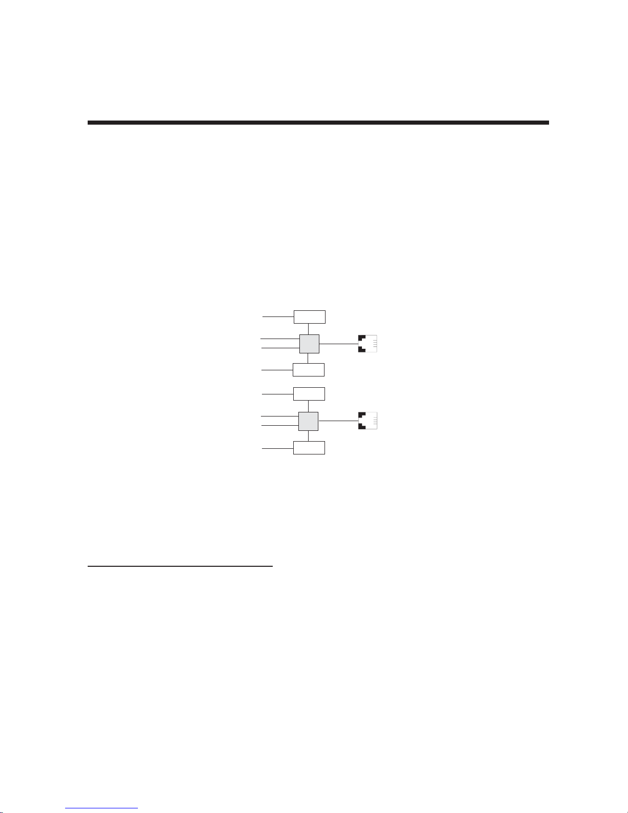
From the perspective of the server PC, the ISIHP-2S/2U (or ISIHI-2S/2U) is an eight-port serial card with eight
devices permanently attached to the serial ports (Figure 1-1).
Com Ports
5
1
2
6
7
3
4
8
Modem
TA
Modem
Modem
TA
Modem
ISDN
RJ-45 jack
3456
RJ-45 jack
3456
Line 1
Line 2
Figure 1-1. Modems and Terminal Adapters
of ISIHP-2S/2U and ISIHI-2S/2U.
The first four ports are the two terminal adapters, each of which appear as two ports. The remaining four ports
are the four central site modems. The following table summarizes the correlation of ports and devices.
Table 2: 2S/2U Ports and Devices
2S/2U Device ISDN Line
Port # Number
1TA1
2TA1
3TA2
4TA2
5 Modem 1
6 Modem 1
7 Modem 2
8 Modem 2
8
Page 9

Chapter 1 - Introduction
1.1.2 ISIHP-4S/4U Serial Card
From the perspective of the server PC, the ISIHP-4S/4U is an sixteen-port serial card with sixteen devices
permanently attached to the serial ports (Figure 1-2).
9
Modem
1
2
Modem
10
11
Modem
3
4
Modem
12
13
Modem
5
6
Modem
14
15
Modem
7
8
Modem
16
RJ-45 Jack
TA
TA
TA
TA
3456
RJ-45 Jack
3456
RJ-45 Jack
3456
RJ-45 Jack
3456
Figure 1-2. Modems and Terminal Adapters
of ISIHP-4S/4U (for ISIHP-4SD, no modems are present)
The first eight ports are the four terminal adapters, each of which appear as two ports. The remaining eight
ports are the eight central site modems. Table 3 summarizes the correlation of ports and devices. The ISIHP4SD contains terminal adapters only; no modems are present.
Table 3: 4S/4U Ports and Devices
4S/4U Device ISDN Line
Port # Number
1TA1
2TA1
3TA2
4TA2
5TA3
6TA3
7TA4
8TA4
9 Modem 1
10 Modem 1
11 Modem 2
12 Modem 2
13 Modem 3
14 Modem 3
15 Modem 4
16 Modem 4
9
Page 10

Chapter 1 - Introduction
1.2 Peripiheral Component Interconnect (PCI) for ISIHP Cards
First developed by companies such as IntelTM, AT&TTM and Digital Equipment CorporationTM, the Peripheral
Component Interconnect (PCI) bus used by your ISIHP card provides high performance and is easy to use.
Because PCI devices contain registers with the device information required for configuration, full auto
configuration of PCI Local Bus add-in boards and components is supported. Performance factors include a
bus data path of 32 bits, and clock speeds of 33 MHz.
1.3 Communication Protocols for ISIHP Por ts
Ports on the ISIHP card can be associated with different protocols, as follows:
Auto-Protocol Terminal adapter automatically detects and switches to use the protocol of the
client terminal adapter.
Auto-Protocol Callback Same as Auto-Protocol except that it causes the host terminal-adapter to dial
back with the same protocol with which the client dialed in.
Central Site Modem The digitally terminated V.90 modems built into ISIHx series cards (except the
4SD model). For the ISIHP-2S/2U, the last four modems should be designated
as Central-Site modems; for the ISIHP-4S/4U, the last eight modems should be
designated as Central-Site modems. (See Port/Device table on previous
page.)
PPP async (Point-to Point Protocol, asynchronous) Protocol allowing computers a dial-up
connection to the Internet. PPP includes error detection, data compression
and other improvements over Serial Line Internet Protocol (SLIP) connections.
V.120 Terminal rate adaptation protocols. These apply to ISDN B-channels when
using a V interface.
X.75 An international standard that allows X.25 packet-switched networks to
communicate with each other. X.75 is a gateway protocol for interconnection
of X.25 public networks.
10
Page 11

Chapter 2 - Hardware Installation
Page 12

Chapter 2 - Hardware Installation
2.1 Introduction
This section describes how to install the ISIHx server card into the expansion slot in your PC.
2.2 Computer Requirements
• Pentium-based PC or compatible (PCI bus required for ISIHP; ISA required for ISIHI)
• Microsoft Windows 2000, Windows 98, Windows Me, Windows NT versions 3.51 and 4.0, SCO Open
Server version 5.0, Novell NetWare, or Linux
• CD-ROM drive, floppy disk drive (for use in cases where drivers are downloaded from web site)
• 800 blocks of hard disk space for UNIX, 100K bytes for Windows NT, 50K bytes for Novell
2.3 Shipping Contents
• ISIHx card
• RJ-45 ISDN cords (1 for ISIHP-1S; 2 for ISIHx-2S/2U; 4 for ISIHP-4S/4U/4SD)
• ISI Product Family CD-ROM (containing drivers, utilities, & documentation)
• Quick Start Guide
2.4 Safety W arnings
1. Never install telephone wiring during a lightning storm.
2. Never install telephone jacks in wet locations unless the jacks are specifically designed for wet locations.
3. This product is to be used with UL and cUL listed computers.
4. Never touch uninsulated telephone wires or terminals unless the telephone line has been disconnected at
the network interface.
5. Use caution when installing or modifying telephone lines.
6. Avoid using a telephone (other than cordless type) during an electrical storm. There may be a remote risk
of electrical shock from lightning.
7. Do not use the telephone to report a gas leak in the vicinity of that leak.
8. To reduce the risk of fire, use only No. 26 AWG or larger Telecommunication line Cord.
12
Page 13
Chapter 2 - Hardware Installation
2.5 Hardware Installation Procedure
1. Before handling the ISIHP card, discharge any static in your body by touching a piece of grounded metal
such as the computer chassis.
2. Carefully remove the ISIHP card from its antistatic bag, handling it only by the mounting bracket and
edges. Do not touch the gold-plated connectors along the bottom edge. (You may want to save packaging
for possible future use.)
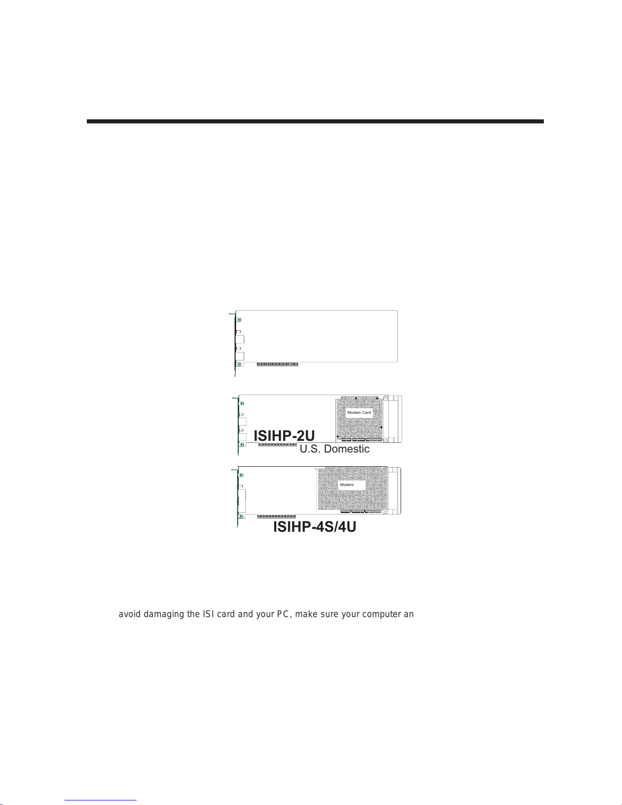
3. Visually inspect the ISIHP-2S/2U/4S/4U/4SD. If you have any concerns about the condition of your ISI
card, call Technical Support at (800) 972-2439.
Intelligent Serial Interface
Hybrid (ISDN/POTS) Cards
Side View
(
ISIHP-2S
International
)
Modem Card
ISIHP-2U
U.S. Domestic
Modem Card
ISIHP-4S/4U
Figure 2-1. ISIHP Cards Side View
4. To avoid damaging the ISI card and your PC, make sure your computer and any peripheral equipment
connected to it are turned off. The ISIHP can be installed in a Pentium equivalent PCI bus computer; the
ISIHI can be installed into a Pentium equivalent computer with ISA slots.
5. Remove the cover of your computer as instructed in your computer’s documentation.
6. Locate the unused expansion slot you will be using for your ISI card and remove the slot cover according
to instructions in your computer’s documentation.
13
Page 14
Chapter 2 - Hardware Installation
7. Install the ISI card in the selected expansion slot in the same manner as any other add-on card according
to your computer’s documentation.
8. Fasten retaining bracket to computer chassis and replace the cover.
9. Connect the ISI to your ISDN telephone wall jack(s) with the provided modular telephone cable.
10. Turn on power to the computer. Now you are ready to install software.
U Interface
ISDN line enters
building
NT1
Device
S Interface
S/T Interface
ISIHP
-2S
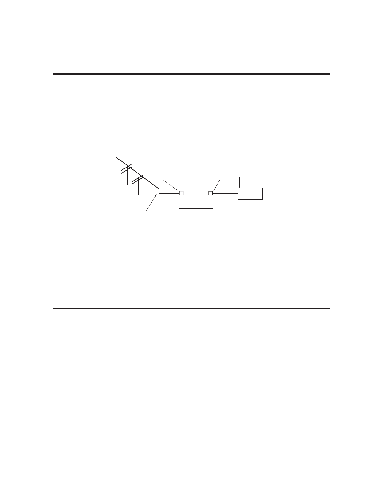
Figure 2-2. ISDN Interfaces at Customer Premises
Note: The ISIHP and ISIHI communicate over ISDN lines. If you don’t have a standard modular jack near your
computer, you should install one or have one installed by your telephone company. In the US, installation kits
and adapters are available wherever telephones are sold.
Note: If S/T-interface ISDN network connection cable is used, the ISDN phone cord should be connected
between the ISDN network connection cable and the NT1 device. If the S/T-interface model (ISIHP-2S, -4S, or
4SD, or ISIHI-2S) is used, then the S/T-interface must be connected to the S-interface on the NT1 device.
14
Page 15
Chapter 2 - Hardware Installation
2.6 LED Indicators
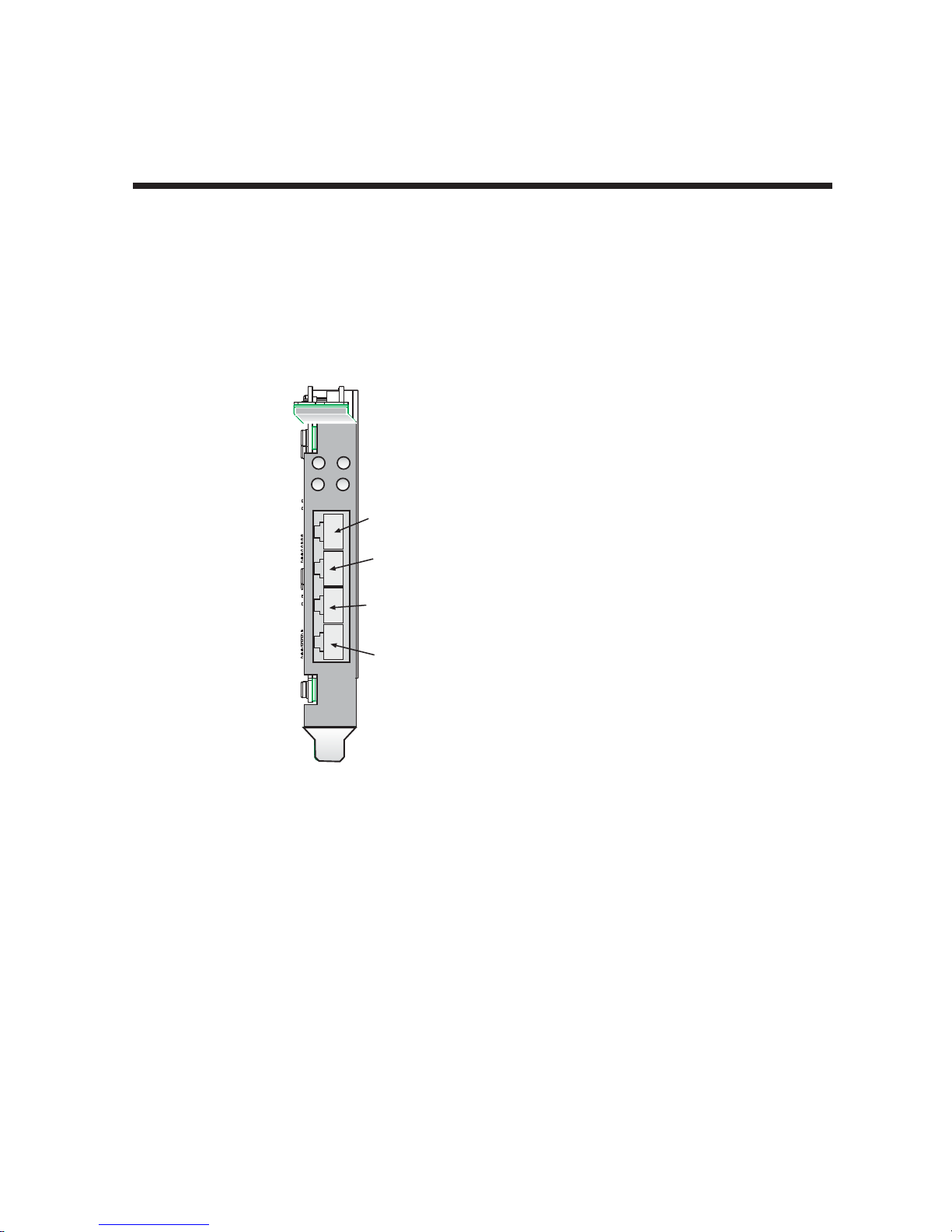
The mounting brackets for the various ISI cards are similar, but the LEDs are labeled differently. Diagrams for
each bracket along with descriptions of the LED indicators are shown in Figures 2-3 thru 2-7.
ISIHP-4U LEDs (one LED per BRI)
Flashes between OFF and RED to
indicate that neither SPID for that
ISDN line has been verified.
1
3
LINE 1
2
4
Line 1
Line 2
Line 3
Flashes between RED and GREEN
to indicate that one SPID is correct.
A solid GREEN display indicates
that both SPIDs are correct.
ISIHP-4S/4SD LEDs (one LED per BRI)
Solid GREEN indicates normal operation.
Flashes between RED and GREEN
to indicate that the device has been reset.
Line 4
Figure 2-3. ISIHP-4U, 4S/4SD LEDs
15
Page 16
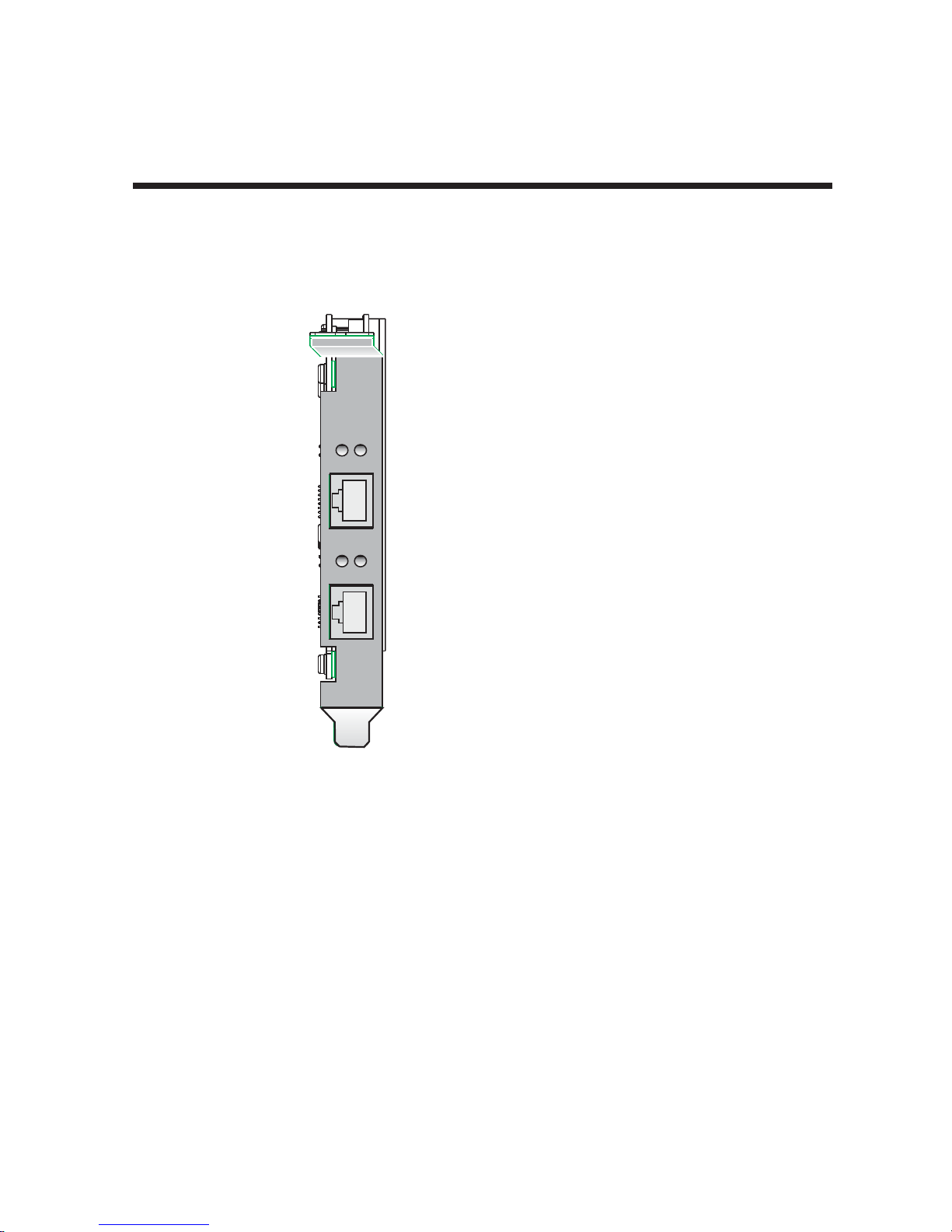
D
P
LINE 1
D
P
LINE 2
Chapter 2 - Hardware Installation
ISIHP-2U LED Indicators
P LED Indicator
Indicates U interface status connection.
Controlled by NT-1, which converts S/T
interface (4-wire ISDN) to U interface
(2-wire ISDN).
When U interface and S/T interface are NOT
active, LED remains off.
Flashes 8 times/second (8 Hz)U interface
is attempting to activate.
Flashes once/second (1 Hz)U interface is
active; S/T interface is not fully active.
Lit, not flashingBoth U and S/T interfaces
are active.
D LED Indicator
Lights when the ISIHP-2U is turned on.
Flashes until SPIDs are verified with the
central office switch; then remains lit without
flashing.
Indicates data link layer status.
Figure 2-4. ISIHP-2U LEDs
16
Page 17
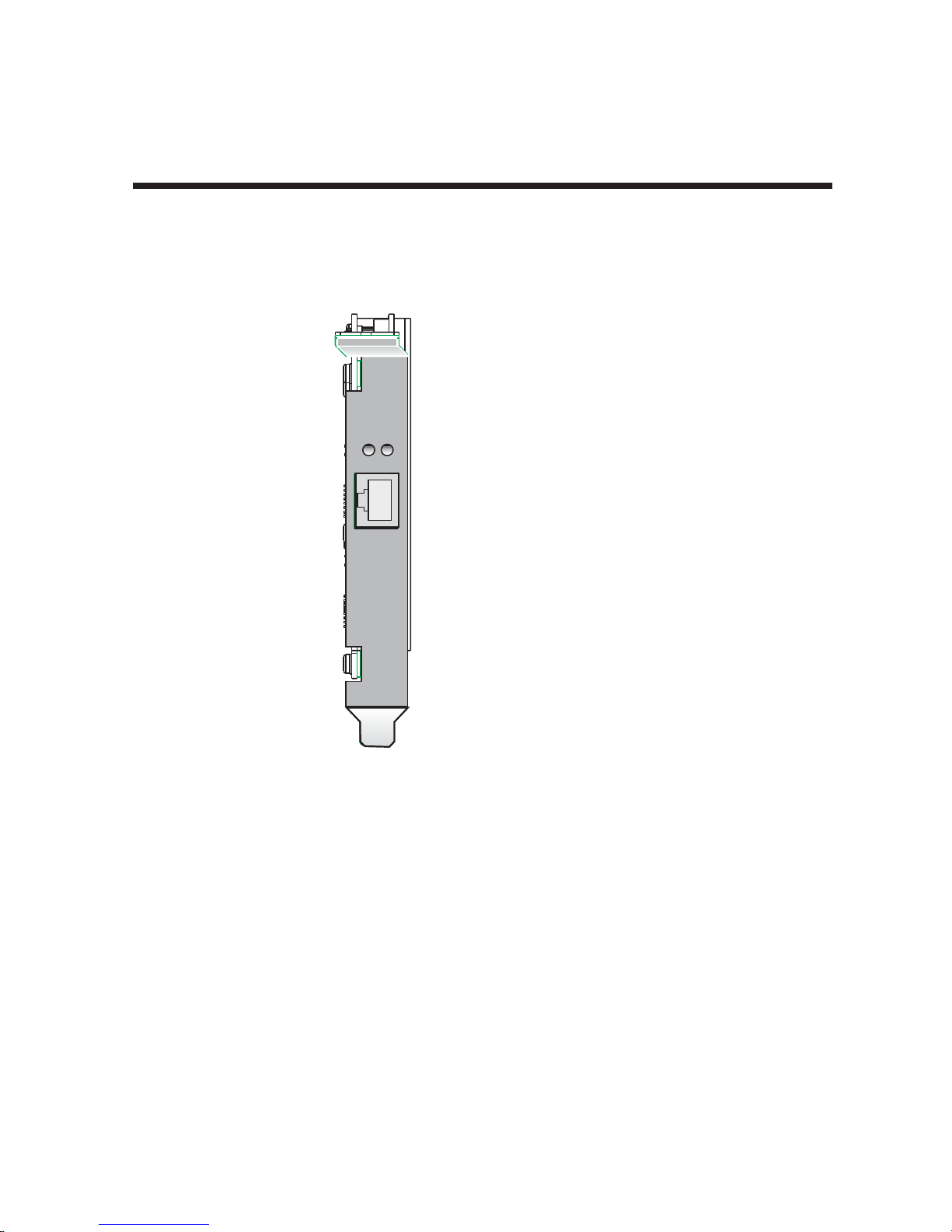
B2
s
B1
LINE 1
D
P
LINE 2
Chapter 2 - Hardware Installation
ISIHP-1S LED Indicator
B1 LED Indicator
When lit, indicates active
or voice connection on
B-channel 1.
B2 LED Indicator
When lit, indicates active
or voice connection on
B-channel 2.
Figure 2-5. ISIHP-1S LEDs
17
Page 18
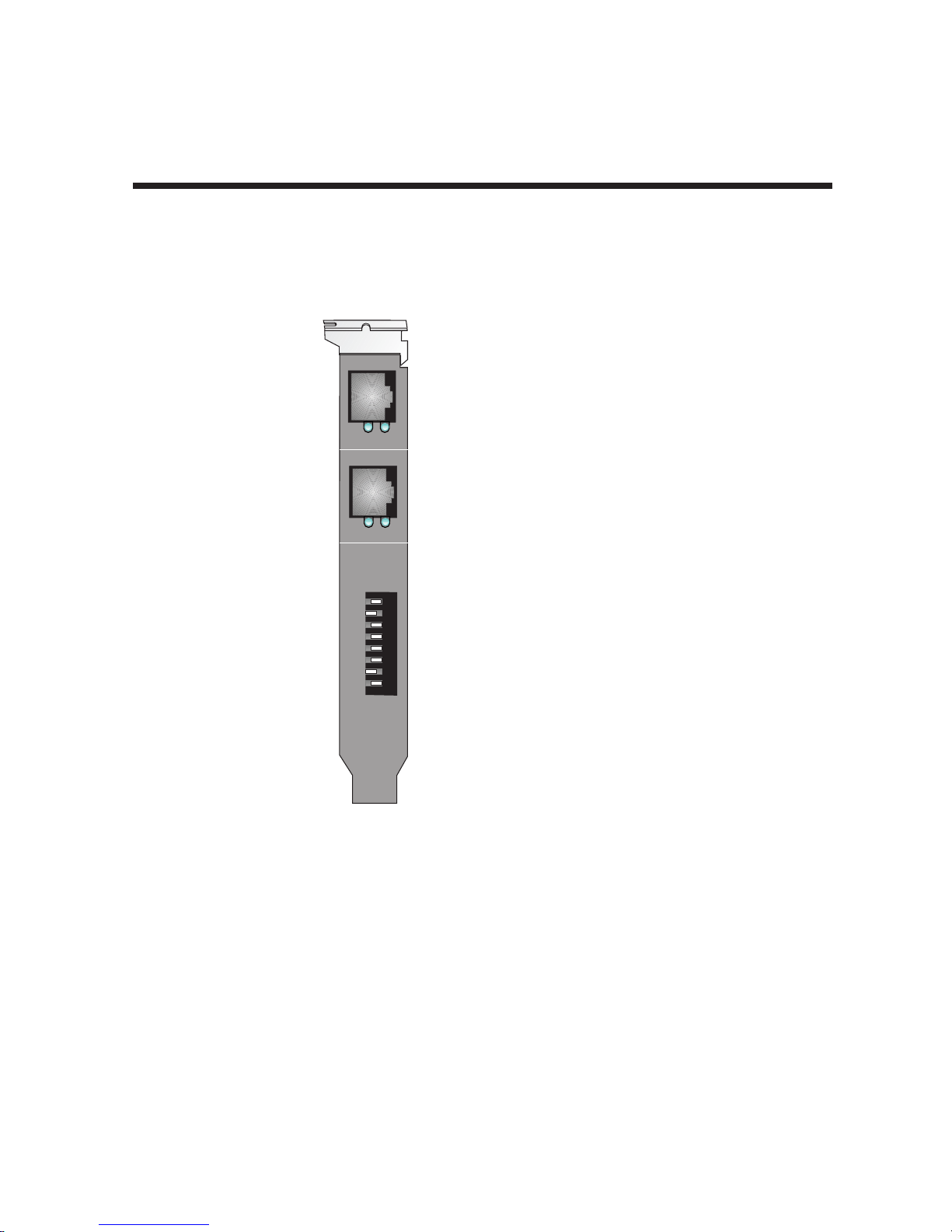
LINE 1
B1 B 2
LINE 2
B1 B 2
I
O
A
D
D
R
Chapter 2 - Hardware Installation
ISIHI-2S LED Indicators
B1 LED Indicator
When lit, indicates active or
voice connection on B-channel 1.
B2 LED Indicator
When lit, indicates active or
voice connection on B-channel 2.
The settings of the multiple DIP switch
unit on the mounting bracket determine
the base Input/Output address for the
ISIHI-2S/2U card. Input/Output
(I/O) addresses are used to route
information to and from the card.
Figure 2-6. ISIHI-2S LEDs
18
Page 19
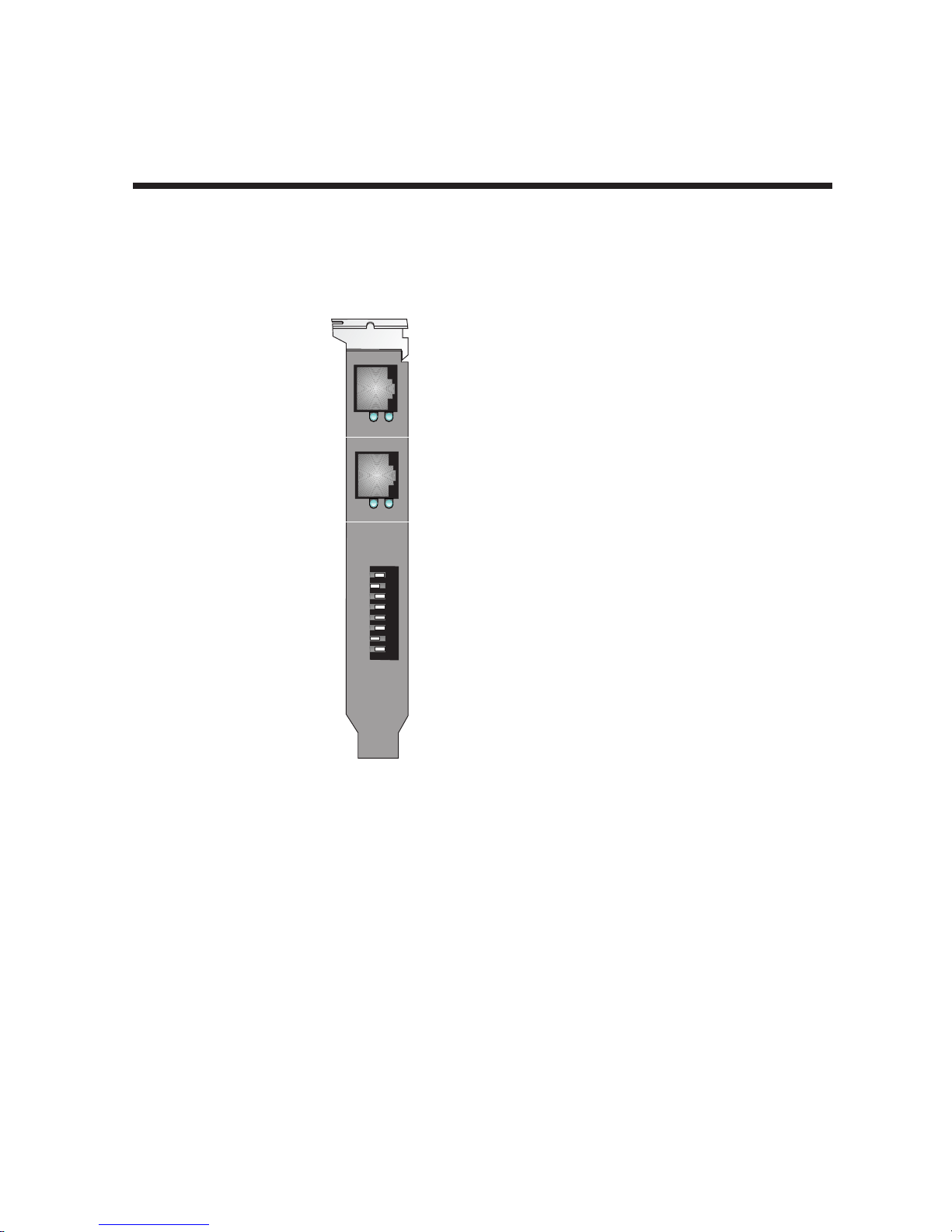
LINE 1
LINE 2
I
O
A
D
D
R
PD
PD
8
7
6
5
4
3
2
1
ISIHI-2U LED Indicators
P LED Indicator
Indicates U interface status connection.
Controlled by NT-1, which converts
S/T interface (4-wire ISDN) to
U interface (2-wire ISDN).
When U interface and S/T interface
are NOT active, LED remains off.
Flashes 8 times/second (8 Hz)
U interface is attempting to activate.
Flashes once/second (1 Hz)
U interface is active; S/T interface is
not fully active.
Lit, not flashingBoth U and
S/T interfaces are active.
D LED Indicator
Lights when the ISIHI-2U is
turned on.
Flashes until SPIDs are verified
with the central office switch;
then remains lit without flashing.
Indicates data link layer status.
The settings of the multiple DIP switch
unit on the mounting bracket determine
the base Input/Output address for the
ISIHI-2S/2U card. Input/Output
(I/O) addresses are used to route
information to and from the card.
Chapter 2 - Hardware Installation
Figure 2-7. ISIHI-2U LEDs
19
Page 20

Chapter 3 - Software Installation
Page 21

Chapter 3 - Software Installation
3.1 Introduction
This chapter describes software/driver installation for the ISI cards when used in Windows 2000, Windows
NT4, Windows NT3.51, Novell, Linux, and SCO Open Server 5. We also describe installation of MultiTech’s
Management Software for use with ISI cards under Windows 2000.
3.2 Installing ISIHI Software for Windows 2000
1. Turn off the PC.
2. The ISIHI card must already be installed in an ISA expansion slot in the PC. If it is not, follow the PC
manufacturer's instructions concerning installation of expansion cards.
Note: Observe standard precautions regarding electrostatic discharge (ESD) when handling the ISIHI board.
During installation, handle the ISIHI circuit card by its edges and keep one hand in contact with the PC
chassis.
3. Set the Base I/O Address and the Interrupt Request (IRQ) values per the table below. The I/O Address
DIP Switch is on the end plate of the ISIHI; the IRQ Jumper Block is on the component side of the circuit
card, lower middle area.
Table 4: Recommended Base I/O Address and IRQ Values
ISIHI-2S/2U Base I/O IRQ
Initial 8 port board 210h 10
First 8 port upgrade 220h 11
Second 8 port upgrade 230h 12
Third 8 port upgrade 240h 15
Address
4. Turn on the PC and start Windows 2000.
5. Insert the ISI installation CD into the CD drive in your computer.
6. Go to
7. At the Choose a Hardware Task screen, select "Add/Troubleshoot a device." Click Next.
8. At the Choose a Hardware Device screen, select "Add a new device." Click Next.
9. At the Find New Hardware screen, select "No, I want to select the hardware from a list." Click Next.
10. At the Hardware Type screen, select "Multi-port serial adapters." Click Next.
11. At the Select a Device Driver screen, click on Have Disk.
12. At the Install from Disk screen, enter the path of the driver files (i.e., the file directory location, in most
13. In the Models list, highlight "Multi-Tech ISI4608-ISA 8 Port Serial Card." A comment screen appears
Start | Settings | Control Panel | Add/Remove Hardware
cases on CD-ROM). Click OK.
indicating that the Base I/O Address and IRQ must be specified for the ISIHI card. Click OK.
. Click Next.
21
Page 22

14. The Add New Hardware Wizard Properties screen appears.
a. In the Resource Settings field, select "Input/Output Range" and click on Change Setting.
The Edit Input/Output Range screen appears.
Select the value that matches the Base I/O Address value that you have already set on
the ISIHI board in Step 2. Click OK.
b. In the Resource Settings field, select "Interrupt Request" and click on Change Setting.
The Edit Interrupt Request screen appears.
Select the value that matches the IRQ value that you have already set on the ISIHI
board in Step 2. Click OK. At the Resources tab, click OK again.
15. At the Start Hardware Installation screen, click Next.
16. A completion screen appears. Click Finish.
17. You will be prompted to restart your computer. Click Yes.
Chapter 3 - Software Installation
22
Page 23

Chapter 3 - Software Installation
3.3 Installing ISIHP Software for Win 2000
Note: A series of ‘installation wizard’ screens will appear repeatedly during this procedure (step 12). This is
not an error. Do not discontinue the procedure when the ‘installation wizard’ screens repeatedly appear.
1. Shut down Windows 2000 and turn off the PC.
2. Install the ISIHP can in an available PCI expansion slot in the PC. Follow the PC manufacturer's
instructions concerning installation of expansion cards.
Note: Observe standard precautions regarding electrostatic discharge (ESD) when handling the ISIHI board.
During installation, handle the ISIHI circuit card by its edges and keep one hand in contact with the PC
chassis.
3. Turn on the PC and start Windows 2000.
4. Insert the ISI driver CD-ROM into the CD-ROM drive. Windows 2000 will detect the ISIHP card. The
Found New Hardware Wizard- Welcome screen will appear. Click Next.
5. The Install Hardware Device Drivers screen appears. Select "Search for a suitable driver ..." and click
Next.
6. The Locate Driver Files screen appears (Windows 2000 is seeking the driver for the ISIHP card). Select
“CD-ROM drives” and click Next.
7. The Driver File Search Results screen appears. Click Next. A progress screen will appear briefly while
files are being copied.
8. A completion screen will appear. Click Finish.
9. Immediately after the ISI driver installation has been completed, another Found New Hardware screen will
appear briefly indicating that the “MultiTech ISI Port” has been detected.
10. A second sequence of ‘installation wizard’ screens appears. This sequence of screens deals with the
setting up of ISI ports. The first screen in this sequence is the Found New Hardware Wizard -- Welcome
screen.
11. The Found New Hardware -- MultiTech ISI Port screen will appear once for each modem and terminal
adapter on the ISIHP card:
• 16 times for the ISIHP-4S/4U/4SD (only 8 devices can be installed on the 4SD)
• 8 times for the ISIHP-2S/2U/1S (only 4 devices can be installed for the ISIHP-1S)
12. The Install Hardware Device Drivers screen appears. Select “Search for a suitable driver ... “. Click Next.
13. The Locate Driver Files screen appears (Windows 2000 is seeking the ISI Port device driver). Select “CD-
ROM drives” and click Next.
14. The Driver Files Search Results screen will indicate that the “isiport.inf” file has been found on the CDROM. Click Next.
15. A completion screen will appear. It will indicate that the first “MultiTech ISI Port” has been set up
successfully. Click Finish.
The Found New Hardware -- MultiTech ISI Port screen will appear many times after the ISI driver has
been located. On this screen, the messages “Found New Hardware” and “Installing ...” will appear
alternately. Repetition of these screen sequences is normal and is not an error.
16. Driver installation for the ISIHP card is complete.
23
Page 24

Chapter 3 - Software Installation
3.4 ISIHx for Win 2000: Installing ISI Management Software (server
OSs only)
If you are using a Windows 2000 Server operating system ("Server" or "Advanced Server"), you must decide
whether you want to use the MultiTech ISI Management Software in conjunction with your ISIHx board. The
ISI Management Software is shipped with the ISI card.
1. Turn on your computer and start Windows 2000.
2. Insert the CD-ROM containing the ISI Management Software into your CD-ROM drive.
3. Go to
4. The ISI Management setup screen appears. At the Welcome screen, click Next.
5. A progress screen appears while files are copied. If the Error Creating WWW Server message appears, it
6. A completion screen appears. Select "Yes, I want to restart my computer now" and click Finish.
7. After the computer has restarted, the installation of the driver and of the ISI Management Software will be
Start | Run
would be
may indicate that there was an attempt to install the ISI Management Software on a client version of
Windows 2000. (The ISI Management Software can be installed only in the
Windows 2000 Advanced Server
complete.
. In the Run window, enter the file path of the ISI Management software. Typically, this
E:\SERVCARD\UTILITY\MGMT\SETUP.EXE
operating systems.)
. Click OK.
Windows 2000 Server
and
24
Page 25

Chapter 3 - Software Installation
3.5 ISIHx for Windows 2000: Installing TAs and Modems
to COM Ports
Installation of Windows 2000 driver software must be completed before you can install the terminal adapters
and modems of the ISIHx card.
1. Go to
2. The Location Information screen appears. Enter the appropriate area code and access number. Click OK.
3. At the Phone and Modem Options screen, click on the Modems tab and click Add.
4. At the Install New Modem screen, click on "Don't detect my modem ... " and click Next.
5. If the software driver CD-ROM (or other media, in cases of using drivers downloaded from the MultiTech
6. If you are installing an ISIHP-1S card, go to step 25 for special instructions and then return to step 7.
Installing Terminal Adapters to COM Ports.
7. The Add/Remove Hardware Wizard screen will appear. Click “Have Disk ... .”
8. The Install from Disk screen will appear. Type or browse for the file path of the terminal adapter software
9. The Install New Modem screen appears. Highlight the terminal adapter protocol to be used. Click Next.
10. The ‘Install New Modem - Port List’ screen will appear.
Start | Settings | Control Panel | Phone and Modem Options
web site) is not already in the appropriate disk drive in the PC, insert it now.
Otherwise go directly to step 7.
(for example,
E:\servcard\drivers\win2000
). Click OK.
.
11. Highlight the COM ports on which you want terminal adapters to be installed. You must allocate 8 ports
for the ISIHP-4S/4U/4SD, or 4 ports for the ISIHP-2S/2U/1S, or 4 ports for the ISIHI-2S/2U. Click Next.
Note: The ISIHP-1S will only support two modem ports, but it is necessary to allocate four ports temporarily
during installation. The allocated-but-unused ports can be used for a different purpose after installation is
complete.
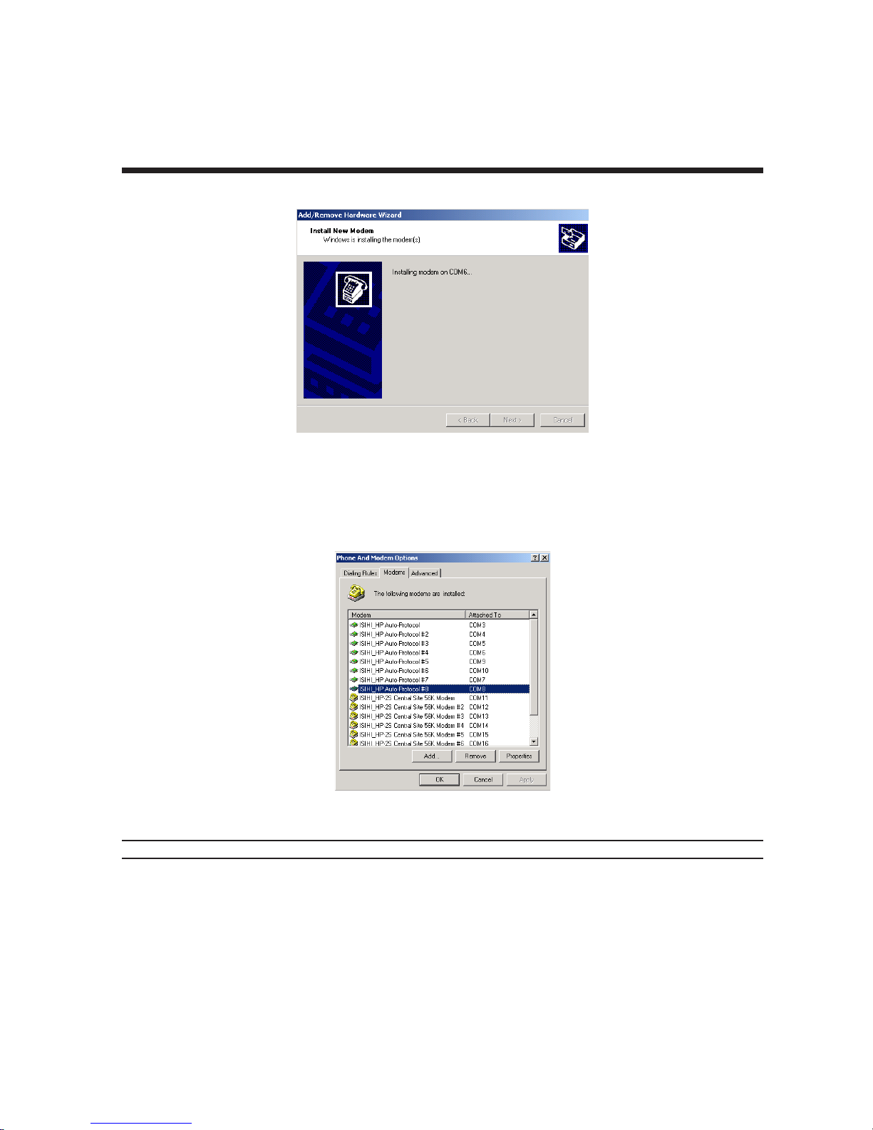
12. A progress screen will appear as TA installation begins. As TAs are installed to the specified COM ports,
a separate screen will appear denoting the process for each COM port.
25
Page 26
Chapter 3 - Software Installation
13. A completion screen will appear. Click Finish.
14. The Phone and Modems Options screen (Modems tab) will reappear and display the TAs that have just
been assigned to COM ports.
Note: If you are installing a ISIHP-4SD, installation is now complete. (The 4SD has no modems).
Installing modems to COM Ports (not applicable to -4SD):
15. At the Phone and Modems Options screen (Modems tab), click Add.
26
Page 27
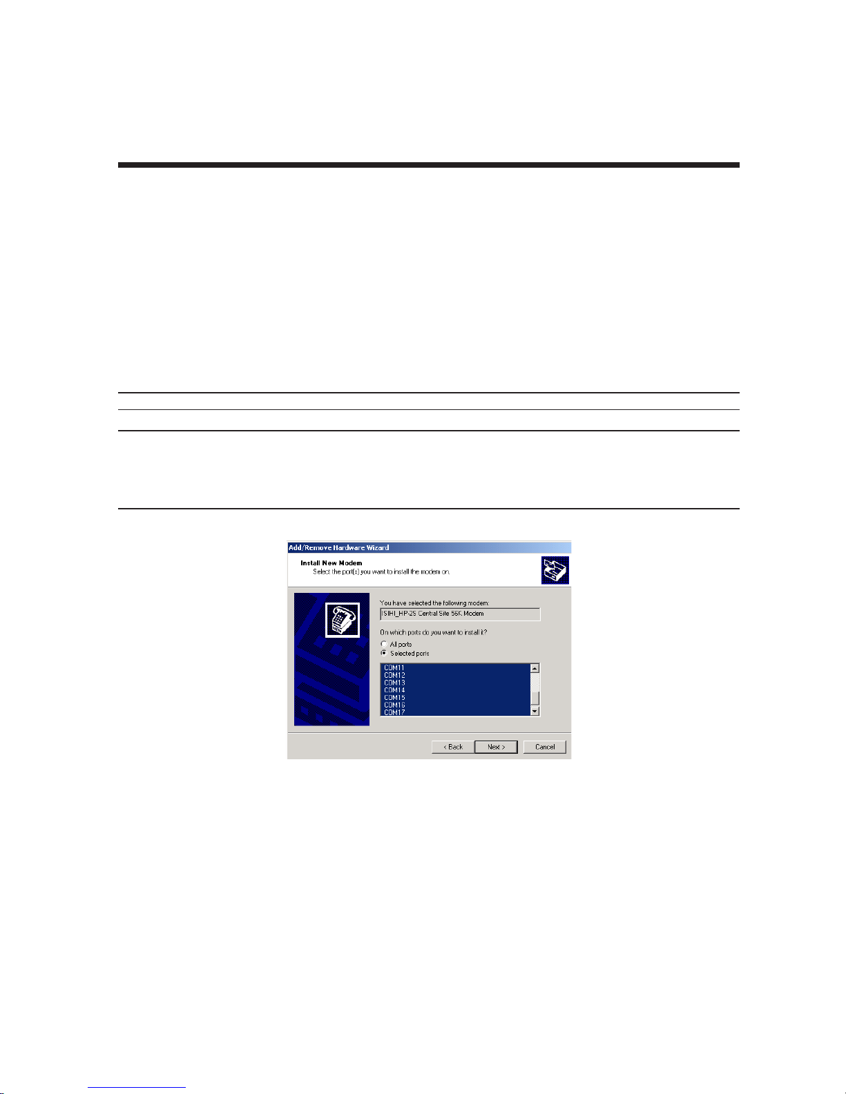
Chapter 3 - Software Installation
16. The Install New Modems screen will appear. Select “Don’t detect my modem ....”. Click Next.
17. A screen listing modem manufacturers and models will appear. Click “Have Disk ....”
18. The Install from Disk screen will appear. Type or browse for the file path of the modem software (for
example,
19. The Install New Modem screen will show a list of MultiTech modem and terminal adapter drivers. Select
the modem type that fits the model of your specific server card.
E:\servcard\drivers\win2000
). Click OK.
• For 1S/2S/4S models, select “ISIHI_HP-2S Central Site 56K Modem". Click Next
• For 2U/4U models, select “ISIHI_HP-2U Central Site 56K Modem". Click Next.
20. The Install New Modem port list screen will appear. Highlight the COM ports on which you want modems
to be installed. You must allocate 8 ports for the ISIHP-4S/4U, or 4 ports for the ISIHP-2S/2U/1S, or 4
ports for the ISIHI-2S/2U. Click Next.
Note: The ISIHP-1S supports only two modems, but you must designate 4 ports during installation.
Note: The COM port numbers used must allow for 4 terminal adapter ports, even though 2 terminal adapter
ports will remain unused. For example, if you allocated COM3, COM4, COM5, and COM6 to terminal adapters
for the ISIHP-1S, you could allocate COM7, COM8, COM9, and COM10 to modems for the ISIHP-1S. COM5,
COM6, COM9, and COM10 would be unused by the ISIHP-1S and so could be allocated to a different function
after installation of the ISIHP-1S is complete.
21. A progress screen will appear as modem installation begins.
22. Screens denoting the installation of modems to specific COM ports will appear.
27
Page 28
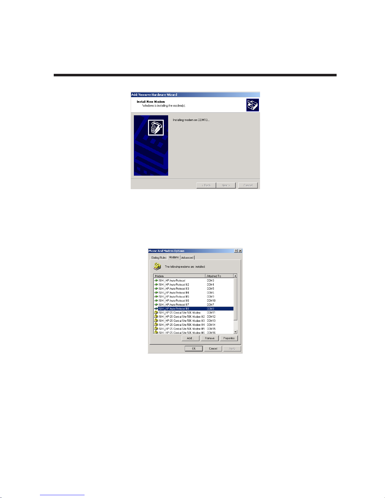
Chapter 3 - Software Installation
23. A completion screen will appear. Click Finish.
24. The Phone and Modems Options screen (Modems tab) will reappear and display the modems that have
just been assigned to COM ports. Installation of terminal adapters and modems to COM ports is now
complete.
28
Page 29
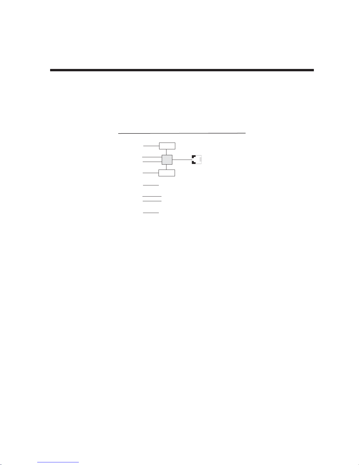
Chapter 3 - Software Installation
25. For the ISIHP-1S card only. The ISIHP-1S is a scaled-back revision of the ISIHP-2S card meant for lowdensity applications where hybrid flexibility (having TAs and modems on the same card) is advantageous.
The diagram below describes the design differences between the ISIHP-1S and ISIHP-2S. It also
summarizes how the ISIHP-1S must be treated during installation.
ISIHP -- Differences between 1S and 2S versions,
especially COM port assignments
Com Ports
5
1
2
6
7
3
4
8
When installing ISIHP-1S software:
(a) treat ISIHP-1S as an 8-port card;
(b) assign first 2 ports as terminal adapters (TAs);
(c) skip two port numbers;
(d) assign next 2 ports as analog modems.
(e) Other devices can use port numbers
that were skipped by the ISIHP-1S.
Modem
TA
Modem
}
ISDN
RJ-45 jack
3456
These ports
are unused
on the ISIHP-1S.
Line 1
29
Page 30

3.5 Remove ISIHx Driver (Windows 2000)
Chapter 3 - Software Installation
1. Go to
2. Click on Add/Remove Hardware. Click Next.
3. Click on “Uninstall/Unplug a device” and click Next.
4. In the subsequent screen, click on “Uninstall a device” and click Next.
5. At the Add/Remove Hardware Wizard screen, highlight the ISI driver file for the specific server card that
6. When you are asked to confirm removal, click on the Yes radio button and click Next.
7. Click Finish. You can remove the driver for only one ISIHx card at a time.
Start | Settings | Control Panel.
you intend to remove. Click Next.
3.6 ISIHx Software Installation Procedure for
Windows NT 3.51/4.0
1. Turn off the PC.
2. The ISIHx card must be installed in an expansion slot in the PC. If not, follow the PC manufacturer's
instructions concerning installation of expansion cards.
• For ISIHP cards. Install the ISIHP card in an available PCI expansion slot in the computer.
• For ISIHI cards. Install the ISIHI card in an available ISA expansion slot in the computer. Set the Base
I/O Address and the Interrupt Request (IRQ) values per the table below. The I/O Address DIP Switch is
on the end plate of the ISIHI; the IRQ Jumper Block is on the component side of the circuit card, lower
middle area.
Note: Observe standard precautions regarding electrostatic discharge (ESD) when handling the ISIHx board.
During installation, handle the ISIHx circuit card by its edges and keep one hand in contact with the PC
chassis.
Table 5: Recommended Base I/O Address and IRQ Values
ISIHI-2S/2U Base I/O IRQ
Initial 8 port board 210h 10
First 8 port upgrade 220h 11
Second 8 port upgrade 230h 12
Third 8 port upgrade 240h 15
3. Turn on the PC and start Windows NT4.0.
4. Insert the driver CD-ROM into the CD-ROM drive.
5. Click
6. The Select Network Adapter dialog box appears. Click Have Disk.
7. The Insert Disk dialog box appears. Type or browse for the path (file directory location) of the Windows
Start | Settings | Control Panel | Network | Adapters
NT driver (for example,
Address
. Then click Add.
E:\SERVCARD\DRIVERS\WINNT\SETUP.EXE
). Click OK.
30
Page 31
Chapter 3 - Software Installation
8. The Select OEM Option dialog box appears. Click OK. A transient dialog box will appear indicating the
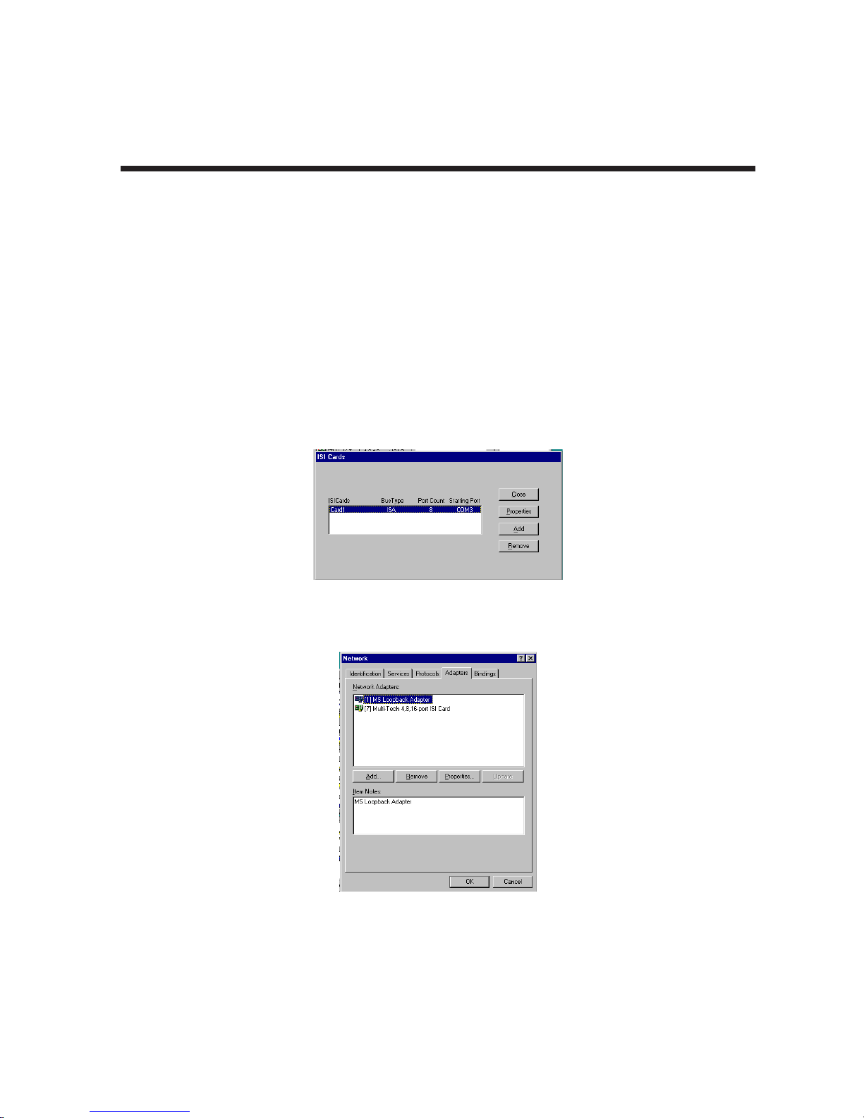
progress of the setup program.
9. The ISI Cards dialog box appears. Click Add.
10. Then the ISI Card Settings dialog box appears. Enter the correct port count:
• allocate 8 ports for 2S/2U cards
• allocate 8 ports for the ISIHP-1S cards
• allocate 16 ports for 4S/4U/4SD cards
11. Select the first port number for ISI devices (TAs or modems), which is usually COM3.
• For ISIHI cards, click "ISA" in the Bus Type field. Enter the Base I/O Address and IRQ as in Step 2
above.
• For ISIHP cards, click "PCI" in the Bus Type field.
12. The ISI Cards dialog box appears again and shows the port resource allocation just made. To add more
cards, click Add and repeat Step 9. After the last ISI card has been added, click Close.
13. The file is copied and "Multi-Tech ISIHP Adapter" appears in the Network Adapters box. Click Close.
14. When prompted to restart your computer, click Yes. The ISIHx card software is now installed.
31
Page 32
Chapter 3 - Software Installation
3.7 Installing ISIHx TAs & Modems to COM Ports in Windows NT
Install terminal adapters:
1. In the Control Panel, double-click the Modems icon.
2. The Modem Properties dialog box appears. Click Add.
3. The Install New Modem dialog box appears. Check the box marked "Don't detect my modem; I will select
it from a list" and click Next.
4. The Install New Modem dialog box appears. In the Manufacturers list, highlight "MultiTech Systems." In
the Models list, select an ISDN protocol then click Next. The valid choices are:
ISIHI_HP Auto-Protocol ISIHI_HP Auto-Protocol CallBack
ISIHI_HP PPP async ISIHI_HP V.110 async
ISIHI_HP V.120 async ISIHI_HP X.75 async
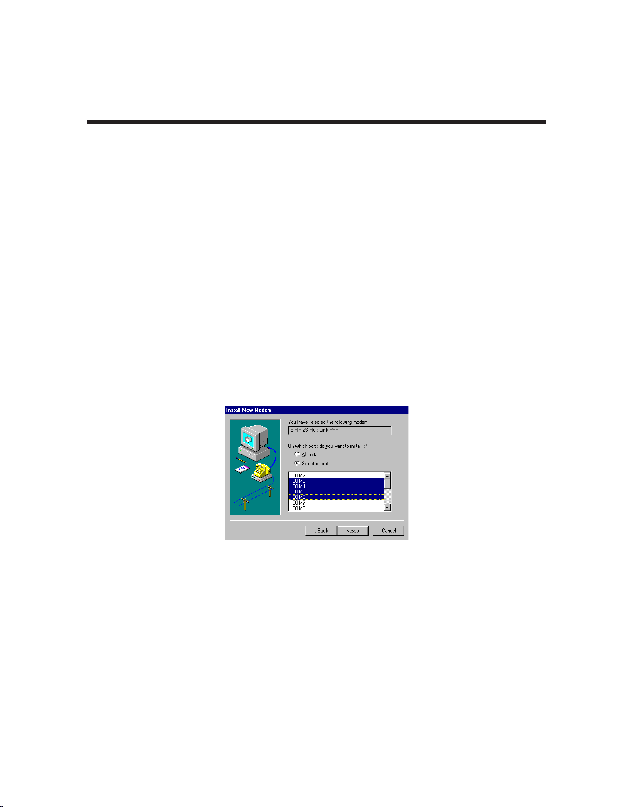
5. The Install New Modem dialog box appears. Select the ports that correspond to:
• the first two ports of the ISIHP-1S card
• the first four ports of the ISIHP-2S/2U card
• the first eight ports of the ISIHP-4S/4U/4SD
Any ports that existed prior to installing the ISIHP appear first in the list of available COM ports. Click
Next. The terminal adapters (the screen describes them as "modems") will be installed to the selected
COM ports.
6. After the terminal adapters install, click Finish to return to the General tab to view COM port assignments
(and make changes if necessary). Now you are ready to install the modems.
32
Page 33
Chapter 3 - Software Installation
Install modem (does not apply to -4SD):
1. On the General tab, click Add.
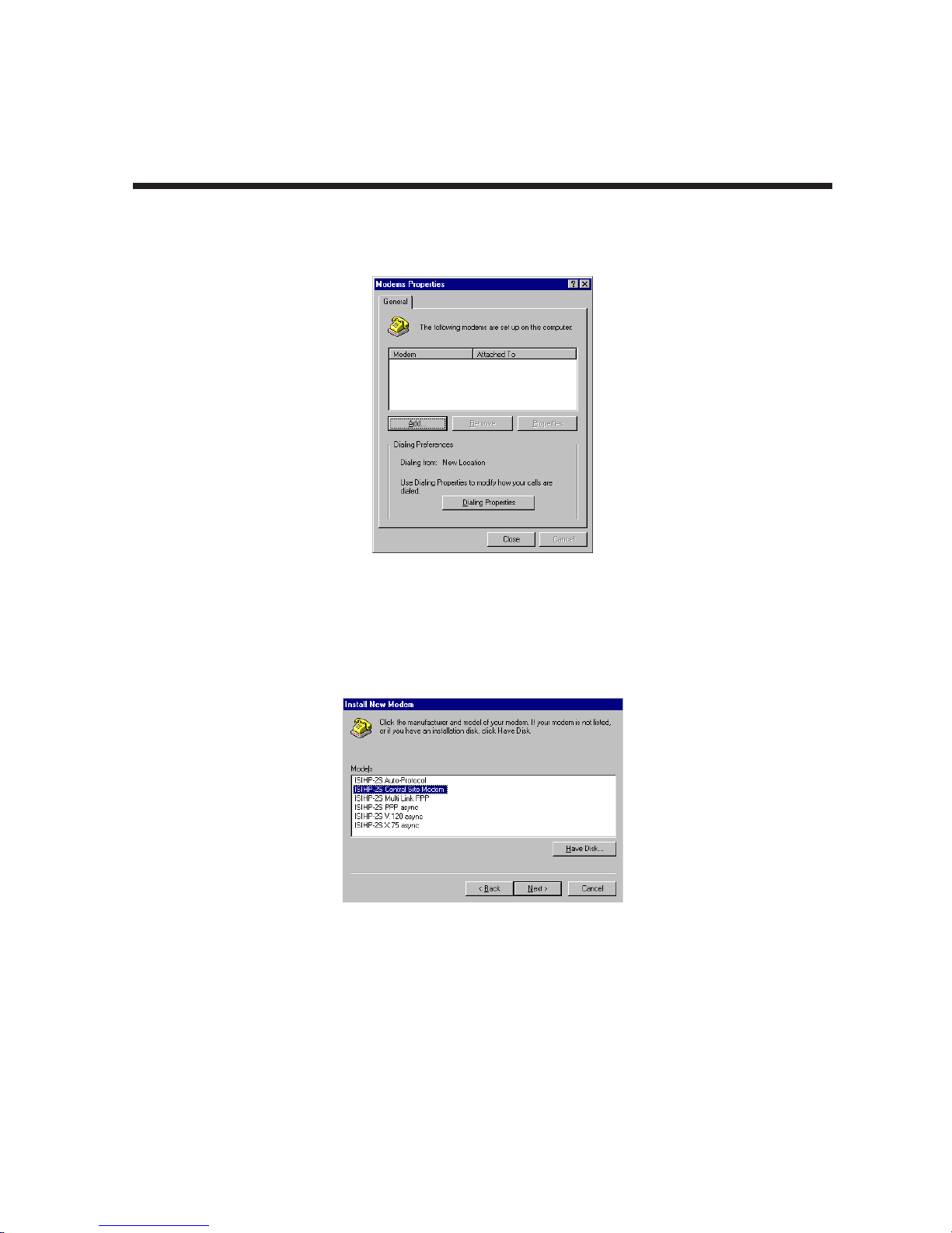
2. The Install New Modem dialog box appears. Check the box marked Don't detect my modem; I will select it
from a list. Then click Next.
3. The Install New Modem dialog box appears. In the Manufacturers list, select "MultiTech Systems." From
the Models list, select Central Site Modems. Then click Next.
33
Page 34
Chapter 3 - Software Installation
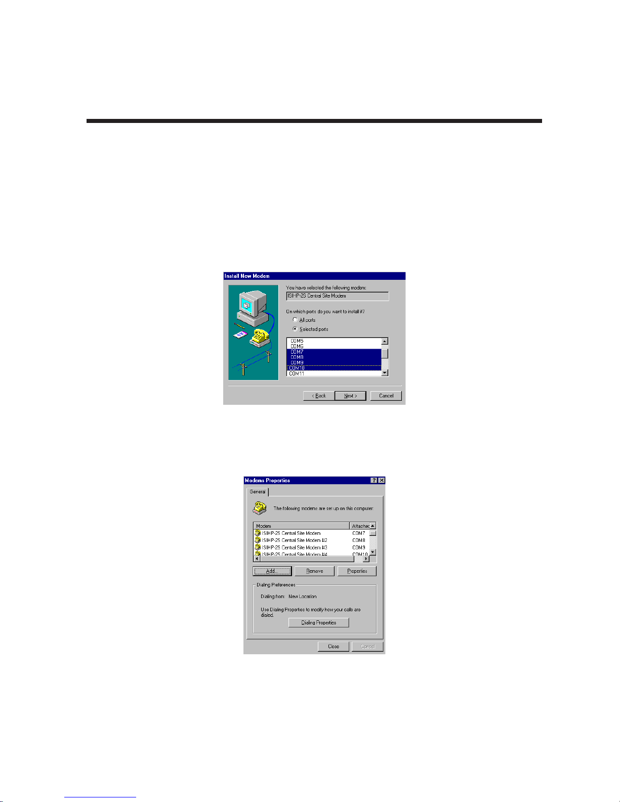
4. Select ports for modem use. Click Next. The modems will be installed to the selected COM ports.
• For the ISIHP-2S/2U, you should have reserved 8 ports during driver installation. The first four of these
ports should have been assigned as terminal adapters (in the previous procedure). Now select the last
four ports, which will be used as modems.
• For the ISIHP-4S/4U, you should have reserved 16 ports during driver installation. The first eight of
these ports should have been assigned as terminal adapters (in the previous procedure). Now select
the last eight ports, which will be used as modems.
• For the ISIHP-1S, you should have reserved 8 ports during driver installation. Recall the port numbers
assigned as terminal adapters (for example, COM3 and COM4); skip two port numbers; then assign the
next two ports as modems (for example COM7 and COM8).
5. After the modems install to the ports, click Finish to return to the General tab.
6. To view COM port assignments and make necessary changes, use the Modem Properties dialog box.
34
Page 35
Chapter 3 - Software Installation
7. Close the Modems Properties dialog box. The message below appears asking if you want to configure
dial-up networking. Click Yes.
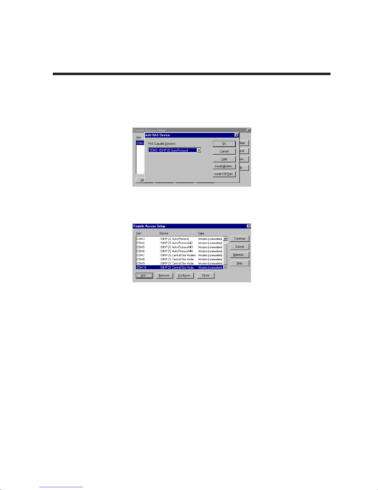
8. The Remote Access Setup dialog box appears. Click Add.
9. Each COM port appears in a separate Add RAS Device dialog box. To add the highlighted device, click
OK.
10. The Remote Access Setup dialog box displays again. Repeat steps 8 and 9 until all devices are added.
11. When all devices have been added, click Continue.
12. After the bindings have been reviewed and stored, you will be prompted to restart your computer. Click
Yes. You are now ready to configure the terminal adapters.
35
Page 36
Chapter 3 - Software Installation
3.8 Removing ISIHx Card and Driver in Windows NT 3.51/4.0
1. Go to
2. Select "MultiTech 4, 8, 16-port ISI card," and then click Remove.
Note: To complete the uninstall procedure, restart your computer.
Start | Settings | Control Panel | Network
. Click on the Adapters tab.
3.8.1 I/O Addresses and IRQ Codes
Unlike the ISIHI, the ISIHP has no DIP switch for I/O addresses and no jumper to determine the IRQ code.
The input/output address and the interrupt request code (IRQ) for the ISIHP are assigned automatically during
driver installation. During any subsequent re-configuring of your PC, you may need to know the assigned I/O
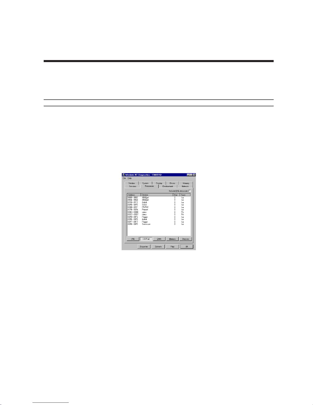
address and IRQ code. To determine the I/O address and IRQ assigned to the ISIHP:
• Click on
• Click on
Start | Settings | Control Panel
Start | Programs | Administrative Tools (Common) | Windows NT Diagnostics | Resources
and select the ISI Cards icon (for Windows NT)
36
Page 37

Chapter 3 - Software Installation
3.9 Configuring the Terminal Adapter
3.9.1 Introduction
North American users must configure the terminal adapter to match network switch type, the service profile
identifier (SPID), and the directory number (DN). For international users, the terminal adapter ships already
configured for NET3, which should work on most phone lines in Europe. However, you may want to customize
settings, regardless of your location. (See “Optional Settings” below.)
You can configure the terminal adapters with the ISDN TA Configuration utility, ConfigMenu, or with AT
commands. Instructions for all three are provided in this manual.
• ISDN TA Configuration Utility. Recommended for computers with Windows 98/Me, Windows NT, and
Windows 2000.
• AT Commands. Use AT commands and S-registers to fine tune TA operation. You enter these
commands in your data communication program’s terminal mode. AT commands and S-registers are
described in detail in a separate chapter of this manual.
3.9.2 North American Users
Before you connect the ISIHI or ISIHP to your network terminator, you must configure it to match the following:
•
Network Switch Type
Select the network switch type your ISDN service uses at its local central office. You can set the TA to
NET3, AT&T 5ESS, NT DMS-100, or US National ISDN-1. If you don't know the switch type, get the
information from the local phone company.
•
SPIDs and DNs
The TA must be configured with the Service Profile Identifier (SPID). The SPID, assigned by the local
phone company, is for the specific BRI line where TA is attached. The SPID field is empty prior to
configuration.
The Directory Number (DN) is the phone number another user would call to contact this TA once it is
attached to the ISDN.
AT command: AT!C6= and AT*!C6
AT commands: AT!N1= and AT*!N1=
AT command: !CO=
Note: SPIDs only apply for North American switch types.
3.9.3 International Users
The terminal adapters ship already configured for NET3, which should work for most telephone lines in
Europe. If you want to customize settings, refer to the “Optional Settings” section of this chapter.
37
Page 38

3.9.4 Optional Settings
•
Data TEI
The Data TEI is the TEI (terminal endpoint identifier) assigned to the data channel. Select
Disable
fixed TEI, or
device connected to the network. When it uses dynamic TEI assignments (Auto TEI), the central office
switch assigns a TEI each time the TA connects to the network. However, the ISDN service provider
may assign a fixed TEI at subscription time, in which case you must configure the TA with the fixed TEI
number. You also can disable the channel, which may be useful when multiple TAs are attached to a
network terminator bus.
•
Voice TEI
The Voice TEI is the TEI assigned to the voice channel. You have the same choices as for Data TEI:
Auto TEI
•
Persistent DTR Dialing
A high DTR (Data Terminal Ready) signal on the serial port indicates that your computer or terminal is
ready to communicate with your TA. DTR normally goes high when a communication program starts or
is ready to dial. Persistent DTR dialing enables the TA to automatically redial the number stored in
memory location 0 whenever DTR is high, and the serial port does not have an active call. You can
enable or disable this feature.
•
Auto Answer Data Calls
Rings to Answer
Select Auto Answer if you want the TA to automatically answer all incoming data calls (option does not
affect analog port). The Rings to Answer number (range: 1—255) selects number of rings the TA waits
before answering an incoming call. Default: 1 ring.
•
Dialing Method
Select either the
provider determines the dialing method. The enbloc method is used for most ISDN dialing. Select the
overlap method if you are working with a private network.
•
Data Protocol
The data protocol, also known as the B-channel protocol and the rate adaptation protocol, is the
language
the ISDN link must use identical protocols.
•
Stored Numbers
The TA can store as many as 10 phone numbers, up to 20 characters each.
•
Dialing Stored Numbers
The TA can dial a number previously stored in directory number n using the
command: e.g., DS3
, fixed TEI number, or
spoken over each 64 Kbps channel between two ISDN devices. The devices on both ends of
•
V.120 Protocol( !Z = 5 )
•
PPP Protocol ( !Z = 9 )
•
X.75 Protocol
on the B-channel.
. A TEI is a number used by the central office switch to uniquely identify each
Enbloc
Chapter 3 - Software Installation
Auto TE
AT command: !D3=
Disable. AT command: *!D3=
AT command: $D
AT command: S0=
or the
Overlap
— The ISIHP uses layer 2 of the X.75 protocol as an error correction protocol
dialing method for use when establishing a data call. Your ISDN
AT command: %A97=
AT command: !Z
—for rates up to 64 Kbps on each B channel.
—for rates up to 64 Kbps on each B channel.
AT command: &Z=
&Zn=x
command.
I, a
AT
38
Page 39
Chapter 3 - Software Installation
3.10 ISDN TA Configuration Utility
1. Make sure Windows NT Remote Access Service (RAS), or any other application that is using the modem,
is shut down. To shut down RAS, click
Remote Access Admin and click Server, which will indicate whether or not RAS is running. If it is running,
click Stop Remote Access Service.
2. Insert the Config Utility CD into the drive.
3. From the main desktop of your PC, select
Programs icon. Click Install.
4. The dialog box Install Program CD-ROM appears. Click Next. The Run Installation Program dialog box
appears. Click Finish.
5. The Welcome dialog box for the ISDN TA Configuration Utility Setup program appears. Click Next.
6. The Choose Destination Location dialog box appears.
7. The Setup dialog box appears.
8. The Information dialog box appears. Click OK.
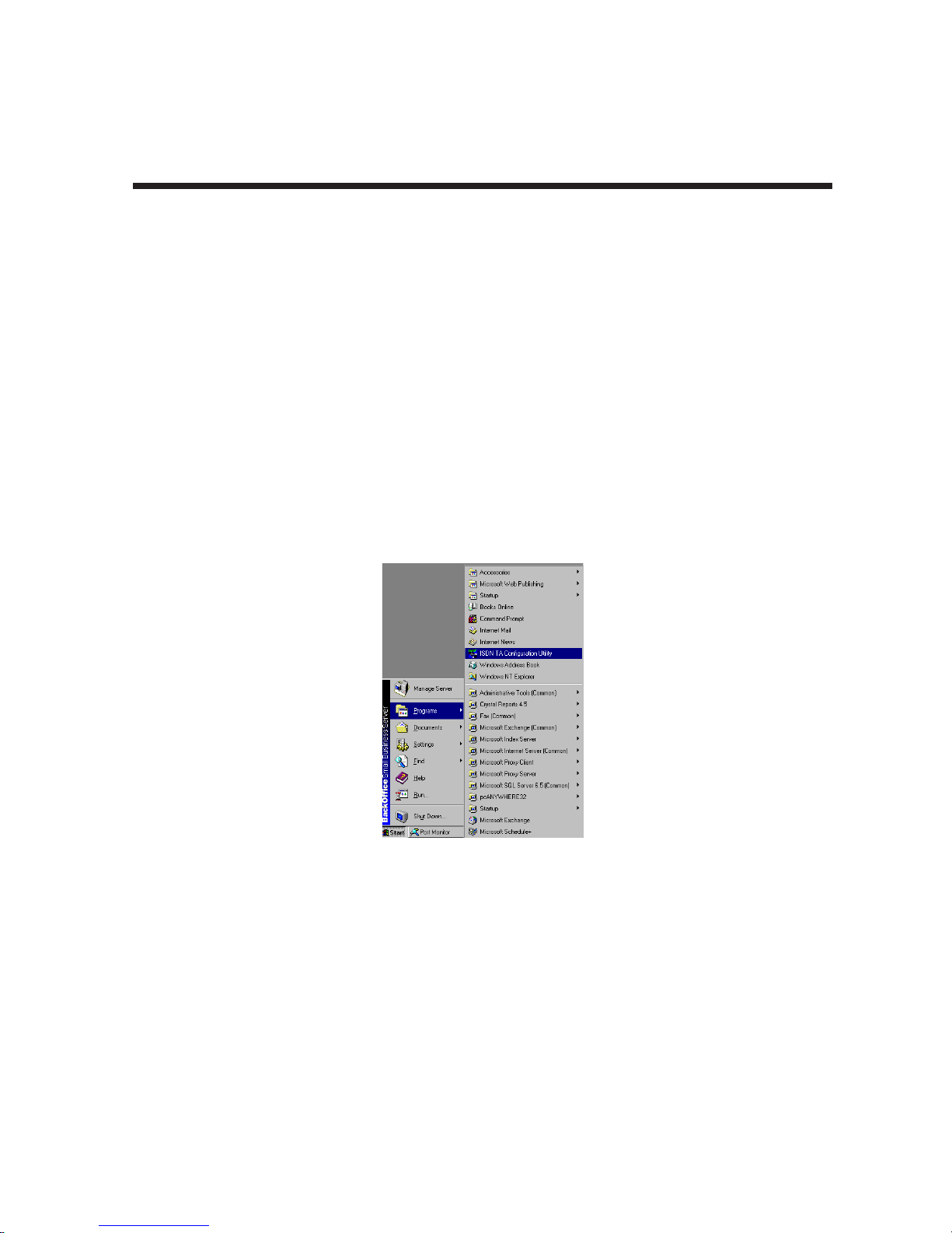
9. Click Start, Programs, and then the ISDN TA Configuration Utility icon.
Start | Programs | Administrative Tools (Common)
Start | Settings | Control Panel
. Click on the Add/Remove
. Then click
10. The Welcome dialog box appears. Click Next.
11. The Searching for TA dialog box appears. Click Next. The next dialog box specifies the TA that has been
identified.
12. The Configuration dialog box appears. If you have questions about choices, click Help. After entering
information in each dialog box, click Next.
13. The SPID dialog box appears (North America only). Referring to your network configuration notes, enter
the appropriate information; then click Next.
39
Page 40

Chapter 3 - Software Installation
14. The Data Protocol Setup dialog box appears. Referring to your network configuration notes, enter the
appropriate information; then click Next.
15. In the Save Configuration dialog box, enter a name to store the configuration. Then click Next.
16. To load the configuration, click Next in the Load Configuration dialog box.
17. Then click Finish in the Configured dialog box.
18. The first TA now is configured. Click Back to return to the Configuration dialog box and repeat steps 4
through 9 to configure the remaining TA(s). If you install multiple ISIHI or ISIHP cards in the same PC,
you must configure two TAs per 2S or 2U card installed or four TAs per 4S, 4U, or 4SD card. For the
ISIHP-1S, you configure only one TA. For example, if you install four ISIHP-2S/2U cards in one PC, you
have to configure eight TAs (two per card).
19. After all TAs are configured, close the ISDN TA Configuration utility.
40
Page 41
Chapter 3 - Software Installation
3.11 ConfigMenu Configuration Utility
The ConfigMenu configuration utility can be used as another means of configuring the TA. ConfigMenu is
installed in the TAs as part of the firmware.
1. Start a data communication program and select the COM port where the TA is connected.
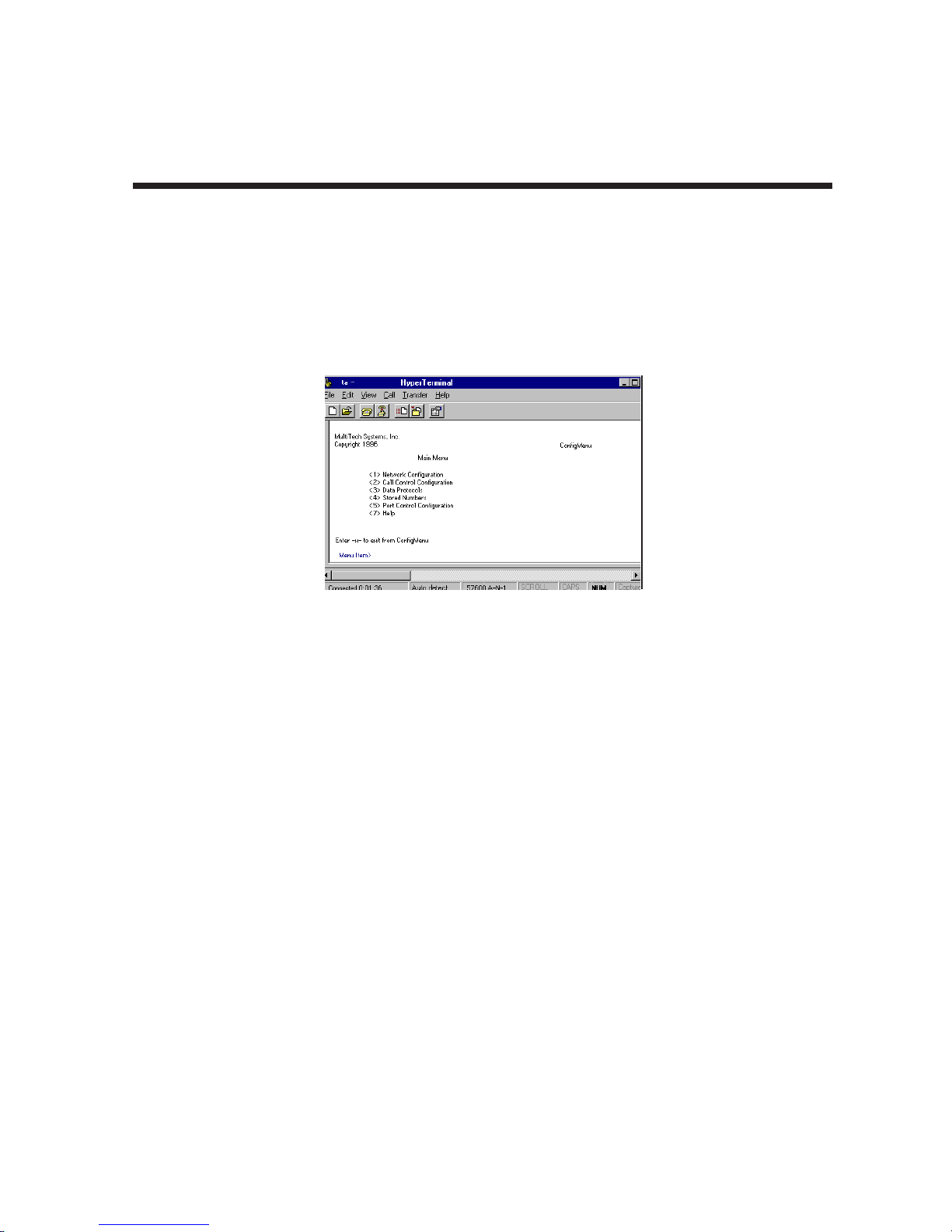
2. In the communication program dialog box, type "AT@CONFIG" and press ENTER. ConfigMenu’s Main
Menu appears (see screen below).
3. To select menu item, type its number and press ENTER. A submenu then appears where you can make
selections. At the lowest level, you can change a configuration option by selecting a number or typing a
value and pressing ENTER.
4. When you finish, close ConfigMenu by typing x and pressing ENTER.
5. You will be prompted to decide whether to save the configuration when you exit the ConfigMenu program.
Type y to have ConfigMenu automatically save the configuration.
3.11.1 ConfigMenu Menus
Network Configuration Configures network parameters such as switch type, data and voice TEIs, and
data and voice MSNs. When you finish, select Save Network Configuration to
save your work.
Call Control Configuration Changes how the TA originates and answers calls. Options include Auto
Answer, Rings to Answer, Dialing Method, and Persistent DTR Dialing.
Data Protocol Changes rate adaption protocol used by the TA.
Stored Numbers Stores up to ten phone numbers ( maximum of 20 characters each). Stored
number 0 is the phone number that will be dialed if persistent DTR dialing is
enabled.
Port Control Configuration Configures TA’s serial port, including how TA responds to control signals on
the serial interface.
Help Menu Provides assistance in navigating through the TA menu system or viewing the
firmware version numbers of the ISIHI or ISIHP card.
41
Page 42

Chapter 3 - Software Installation
3.12 Terminal Adapter AT Commands
You can configure the terminal adapters using AT commands just as you would configure an analog modem.
Use this method if you prefer to work with AT commands or if you have a special requirement not addressed
by either of the configuration utilities.
1. Start a data communication program and select the TA COM ports to be configured.
2. Referring to records made for your system, enter AT commands in the terminal window of the data
communications program.
3. When you finish, use the &W command to save your new configuration and to select it to load
automatically when the ISIHP is turned on.
4. Close the data communications program. For more information, see the chapter "AT Commands and SRegisters" in this manual.
3.13 NetWare Driver Installation
Multi-Tech Systems provides AIO drivers for the ISIHx cards, so they can function with Novell compatible
asynchronous applications (e.g., NetWare Connect). The AIO driver is simply an NLM (NetWare Loadable
Module) that runs on the file server. Drivers must be loaded on the file server where the board is installed.
Drivers can be loaded from the file server’s console prompt or incorporated for autoloading in the
AUTOEXEC.NCF file.
The file AIOMTS.MDC contains Novell (version 3.12 and higher) initialization strings for ISI products not
previously listed for use with BorderManager and Netware Connect. The file AIOMTS.MDC is included on the
ISI Product Family CD. To benefit from the AIOMTS.MDC file, you must copy it from the CD to the appropriate
directory on your computer.
• To use AIOMTS.MDC under Border Manager, RAS, NIAS in 4.2 or 5.x copy AIOMTS.MDC to your
System directory.
• To use AIOMTS.MDC under Novell NetWare 3.x, 4.1, 4.11 with NetWare Connect 2.0.28 or higher
copy AIOMTS.MDC to your System and System/AIO directory.
• To install the Multi-Tech AIO driver, copy the file
from a workstation on the network. Use
F:\SYSTEM
COPY E:\SERVCARD\DRIVERS\NOVELL\AIOSIX.NLM
• If you have downloaded the ISI driver from the MultiTech web site onto a diskette, use
A:\NOVELL\AIOISIX.NLM F:\SYSTEM
AIOISIX.NLM
to the system directory of the file server
COPY
• To load the driver, go to the system or PC console (where the ISI card is installed) and enter at the
prompt LOAD AIOISIX [port=W] [interrupt=X] [name=Y] [note=Z]
• For PCI-bus cards (ISIHP models) Netware will set up the interrupt (IRQ) and I/O address
automatically.
• To install the ISI card scripts, copy aiomdms.mdc to
overwrite the existing aiomdms.mdc file.
F:\SYSTEM\AIO\DIRECTORY
. Click Yes to
42
Page 43

Chapter 3 - Software Installation
3.13.1 Configuring Ports for NetWare Connect
When the driver is installed, it will allocate consecutive ports for the ISI card as follows:
• 16 consecutive ports for the ISIHP-4S/4U/4SD. Note that, for the ISIHP-4SD, only 8 of these ports will
be used; the other 8 ports will be considered “broken.” After installation of the ISIHP-4SD is complete,
the “broken” ports can be allocated to a different purpose.
• 8 consecutive ports for the ISIHI-2S/2U or ISIHP-2S/2U
• 8 consecutive ports for the ISIHP-1S. However, upon inspection, the Netware OS will initialize the first
pair of ports (terminal adapters), label the second pair of ports “broken,” initialize the third pair of ports
(modems), and label the fourth pair “broken.” After installation of the ISIHP-1S card is complete, the
“broken” ports can be allocated to a different purpose.
To set up NetWare Connect ports, enter LOAD NWCCON at the NetWare console prompt. LOAD NWCCON
opens the NetWare Connect Configuration Utility. Select the appropriate menu options (modem type, speed,
flow control, etc.).
3.13.2 Removing the Driver (Novell)
In Novell, remove file AIOISIX.NLM from the system directory and make the appropriate changes to the
Autoexec.ncf file.
3.14 SCO Open Server 5 Driver Installation
The ISI driver for SCO Open Server 5 is shipped on CD-ROM (FAT file system) and can also be downloaded
from the Multi-Tech web site. In both cases, the driver files are compressed (“tarred”). Users installing from the
CD-ROM should begin at “To install from CD-ROM” directly below. Users installing from a floppy disk should
skip down to “To install driver from floppy disk” later in this section. The filename of the SCO5 driver in its
tarred form is sco50x.tar.
This present installation section is task-oriented with minimal explanation of procedural steps. The section
"Multi-Tech Installation Script" provides additional details to aid in installation.
3.14.1 Install from CD-ROM
1. # mount -r /dev/cd0 /mnt
2. # cd /mnt
3. # cd servcard/drivers/sco50x
4. #cp sco50x.tar /
5. # cd <ENTER>
43
Page 44

Chapter 3 - Software Installation
3.14.2 Format a Floppy Disk for SCO5
1. At the Unix prompt, run the scosh program.
2. Select Manager.
3. Select Archive.
4. Select Format.
5. Make sure that Device is pointed to the floppy drive.
6. Select Continue.
3.14.3 Untar the Driver File and Copy Files to Floppy Disk
1. Make a temporary directory for the ISI driver files.
# mkdir /isi
2. Copy the tarred isi driver file into the temporary directory.
# cp sco50x.tar /isi
3. Untar this file and put its contents into the temporary directory.
# cd /isi
# tar xvf sco50x.tar
4. Copy the untarred (inflated or non-compressed) files to a floppy disk
# cd /isi/unifiedinstimg301
#scosh
- Select Manager.
- Select Archive.
- Select Create.
- Press space bar to highlight tmp/ and usr/ directories.
- Press <ENTER> to copy.
- Make sure Device is pointed to the floppy disk.
- Make sure that the “Type” is cpio.
- Select Continue.
5. To verify that the files have been copied onto the floppy disk, use these commands:
# scosh
- Select Manager.
- Select Archive.
- Select List.
- Make sure Device is pointed to the floppy disk.
- Select Continue.
44
Page 45

Chapter 3 - Software Installation
3.14.4 Install Driver from Floppy Disk
Users starting with the untarred SCO5 driver on a floppy disk can begin the installation here.
1. Run the custom utility.
2. Select Software.
3. Select Install New.
4. Highlight driver file from local host and select Continue.
5. Select as the Media Device “Floppy Disk Drive.”
6. Select Continue.
7. Highlight “Multi-Tech ISA/PCI ...” and select Install.
8. Enter Y (yes) to continue installing the ISI driver.
9. As many as four ISI cards can be installed in the server. For further details see
Script
step 1.
MultiTech Installation
• If you are installing an ISIHP card, type 0 (zero).
• If you are installing an ISIHI card, type 1, 2, 3, or 4, based on the number of ISIHI cards you are
installing in your system. Type the base I/O address and the IRQ value for each card. Be sure that the
I/O address and the IRQ value match the values set in the DIP switch and jumper block on the ISIHI
card.
10. Type the number of pseudo-devices to be created. For further details see
step 2.
MultiTech Installation Script
• For the ISIHP-1S, type 4.
• For the ISIHP2S/2U/4SD and ISIHI-2S/2U, type 8.
• For ISIHP-4S/4U, type 16.
11. Type Y (yes) to accept the prefix for tty ports. For further details see
12. Type Y (yes) to confirm the selection. For further details see
13. After the driver is installed, press ENTER to continue. For further details see
step 4(last paragraph) and step 5.
14. Exit the custom utility. For further details see
15. Remove the floppy disk and reboot your computer. For further details see
step 7.
MultiTech Installation Script
MultiTech Installation Script
MultiTech Installation Script
MultiTech Installation Script
step 6.
MultiTech Installation Script
step 3.
step 4.
45
Page 46

Chapter 3 - Software Installation
3.14.5 MultiTech Installation Script
The Multi-Tech Installation Script for SCO Open Server 5 systems requests information about how many
boards you want to install, designations for communication
devices you want to create for Multi_View utility. Based on this information, the appropriate driver files will be
installed and linked with your system’s kernel.
1. This text appears on the screen:
You can install up to 4 ISA/PCI cards in a system.
The PCI cards will be autodetected on bootup.
Enter the number of ISA cards you want to install
and configure on your system (0-4):
ports and printer ports, and how many pseudo
Select 0 (zero) if your computer has a PCI bus. This tells the SCO operating system to autodetect the ISI
cards.
2. The following text appears on the screen:
Multi_View is a utility which will allow you to have
multiple sessions on terminals that have multiple
pages of physical memory. In order for this utility
to work with MultiTech’s serial cards, pseudo devices
have to be created in your /dev directory. These
devices are system-wide resources.
Enter the number of pseudo-devices to be created
for the use of Multi_View utility (1 - 256).
The Multi_View utility initializes the multiple-page capability of terminals with multiple pages of memory.
The number specified here is the total number of devices (between 1 and 256) available to all Multi-Tech
terminals and it’s the number of pseudo devices available to the Multi_View utility.
• Specify 8 pseudo devices for each ISIHx-2S or -2U card installed
• Specify 16 for each ISIHP-4S or -4U card installed
• Specify 8 devices for each ISIHP-4SD card installed
For example, if the computer contains three ISIHP-4S cards, you would enter 48.
The ISIHP-1S card is a special case. In the MultiTech Installation Script, you should specify 8 pseudo
devices for the ISIHP-1S card. However, only four of these pseudo devices will actually be used. The first
pair, ttyl1A and ttyl1B, will be used as terminal adapters; the third pair, tty11E and tty11F, will be used as
modems. (In device names like ttyl1A, the fourth character is a lower-case “L”; the device names are,
however, case sensitive.) The remaining ports (the second pair and the fourth pair) are not used and can
be allocated to a different purpose after the ISIHP-1S installation is complete. You must initialize each of
the four ports separately using the enable command (for example, enable ttyl1a).
The ISIHP-4SD is also a special case. In the MultiTech Installation script, you should specify 16 pseudo
devices for the ISIHP-4SD card. However, only the first 8 devices (ttyl1A through ttyl1H) will be used and
these will be used as terminal adapters. The remaining ports (ttyl1J through ttyl1P) are not used and can
be allocated to a different purpose after the ISIHP-4SD installation is complete. Use the enable command
to initialize ports.
46
Page 47

Chapter 3 - Software Installation
3. This text appears on the screen and relates to the “/dev” directory.
This script also creates the devices in your system
to communicate with the ports of ISICOM. The default
prefix for the tty ports is ttyl. The default prefix for
the printer is prnl. Is this acceptable? (y/n/q).
For most users, it’s best to select y, which entails accepting the default values. Then proceed to step 4.
Details for use of non-default port/printer values
the kernel to access the hardware. When you add an ISI card, you must give the ISI ports unique names
so they do not conflict with existing ports or with other devices known to your system. If a device name
has already been assigned to an existing device and the operator assigns that name to a new device,
then the existing device will be
deleted
when the ISI port using its name is created.
a. To use a non-default base name, type N and then enter a basename having less than
five characters. The base name you select will be used for all ports on each card you
install. ISI port designations will have this form:
[
basename prefix][board number][port letter
basename:
board number:
Length is one to four characters.
Values will be 1, 2, 3, or 4, depending on how many ISI cards
are installed in your computer.
port letter:
For ISIHx-2S/2U, use letters A through D for TAs; use letters E
through H for modems. For ISIHx-4S/4U, use letters A through H
for TAs; use letters I through P for modems. (For terminal control
devices, use lower-case letters as port identifiers.)
Device basename selected: _____________________________________
b. After you select a device basename, you are prompted for a printer base name. This
prefix identifies each port that supports a terminal with a printer attached to its auxiliary
port (for transparent printing). Specify a unique printer base name (printer parameters
are outlined in the Multi_Setup Utility section in this manual ).
Printer base name selected: _____________________________________
When you have specified the device base name and the printer base name, press
ENTER to continue.
4. The confirmation screen lists the values you have selected. The following text appears on the screen
(default values are shown):
You have chosen the following setup
The tty prefix is ttyl.
The printer prefix is prnl.
Number of Multi_View pseudo devices
[
user-specified number
].
If these values are correct, type Y and the installation process will continue. If there is an error in any of
the values displayed, type N and the first screen displays. Then re-enter the information for each card.
When you accept the confirmation list (by typing Y), a series of messages displays while the driver is
being installed and the kernel rebuilt. After the terminals have been added to the Terminal Control
database, and when the display says “Press <Enter> to continue:”, then press ENTER. When Installation
complete displays, press ENTER again.
. The /dev directory holds device-information files used by
].
47
Page 48

Chapter 3 - Software Installation
5. Select Host and press ENTER . Remove the diskette from the drive.
6. Select Exit and press ENTER .
7. To reboot the system (required), enter the following commands:
• Type shutdown -g0-y and press ENTER
• Type init 6 and press ENTER .
Driver installation for the ISIHP card now is complete.
3.14.7 Activating Ports in SCO Open Server 5
SCO Open Server 5 provides a device database that monitors the activity of serial ports through which users
can log onto the host. If your ISI ports are used by terminals (e.g., to allow users to log onto your host), you
must create an entry in the system’s device database that furnishes specific information for the terminals that
will be used on each ISI port. The database is referenced each time a user attempts to log in. If there is no
database entry for a particular terminal, access to the host is denied.
1. Turn on your system and verify that the firmware for each ISIHP loads successfully. If the firmware for a
given ISIHP or ISIHI card does not load, none of its ports will be accessible. (If this happens, see
Tech’s Administrative Utility
2. Type the complete name of the first device you want to create in usr/lib/uucp/Devices. Substitute the
specific base name, board number, and port letter for the generic parameters in the expression ttylbx.
Use a lower-case x value for local DTE (terminal) support and an upper case X value for modem control
for each port you want to enable. Example: ttyl2A denotes the second ISI card (2) and the first port on
that card (A). The port status can be altered later, but one setting must be selected at this time. The ACU
line would read as follows:
ACU ttylbX - 9600
3. Repeat this process for each port on each board you have installed. Record the setting you select for
each port.
4. Using device names created in the previous section, type the following command for each port you want
to activate: enable ttylbx
5. Repeat this command for each port you want to activate, using the lower case letter for local terminal use
or upper case for modem control.
dialer name
section in this manual.)
. Replace b, X and dialer-name with appropriate values.
Multi-
Note: Only one of the options (e.g., modem control or local terminal access) should be enabled for any port at
one time. For example, you cannot enable ttyl1a and then enable ttyl1A. To change the status of a port,
disable the current status (disable ttyl1a) and then enable it for the desired status (enable ttyl1A).
3.14.7 Removing the Driver (SCO Open Server 5)
To remove the Multi-Tech Serial Card Driver, enter the configuration utility (e.g., custom for SCO Open Server
5) and follow instructions to remove the entire driver and rebuild the kernel without the ISI driver. If it is
necessary to reinstall the driver due to I/O address or IRQ overlap, remove the driver first.
Note: Remove the driver before permanently removing the ISI card from the computer.
48
Page 49

Chapter 3 - Software Installation
3.15 Linux Driver for Multi-Tech ISI Server Cards
(for PCI and ISA busses)
This is the standard installation procedure for Linux and is applicable to all Linux operating systems of the
correct kernel level (2.0, 2.2, or 2.4). The next major section of this manual,
Drivers for ISI Server Cards (PCI bus only)
Linux 6.2 and 7.0 using the RedHat Package Management System (RPM). Note that RedHat Linux versions
6.2 and 7.0 both use the Linux 2.2 kernel and the applicable ISI driver can be installed using this standard
installation procedure, as well.
, is an alternative installation procedure applicable only to RedHat
3.15.1 LINUX: Pre-Installation Issues
When unpacking the Linux driver, there are two choices, one driver for the 2.0.x kernel (at this writing, it is
filename L300_20X.TAR), and one driver that works for both the 2.2.x kernel and the 2.4.x kernel (at this
writing, it is filename L305_22X_24X.TAR). Be absolutely positive about which kernel you have! Note that
updated driver files may be issued from time to time.
The 'make' utility, GNU C compiler, and the kernel sources need to be installed on your system. If any of these
are missing, the compilation will fail. Most later Linux OSs install these elements automatically .
3.15.2 LINUX: Copying the Driver from the Media
The Linux drivers (for 2.0 and 2.2/2.4 kernels) are shipped in compressed (‘tarred’) form on a CD-ROM
formatted with the FAT file system. In some cases, users may download Linux ISI drivers from the MultiTech
web site onto diskette (in ext2 format). We present instructions for both situations below.
RedHat Linux 6.2/7.0 RPM
3.15.3 LINUX: Copying & Untarring the Driver from CD-ROM
1. Mount the CD-ROM using this command: mount /mnt/cdrom
2. Change directory: cd /mnt/cdrom
3. List the files on the CD-ROM and locate the directory for the kernel in use (2.0 or 2.2/2.4), using this
command: ls
4. Untar the appropriate Linux driver using this command: > tar vxf
Note: At this writing, the filename will be either L300_20X.tar (for 2.0 kernel) or L305_22X_24X.TAR (for 2.2/
2.4 kernel).
{filename}
/isi
3.15.4 LINUX: Copying & untarring the driver from a floppy
The ISI driver
have been installed. Issue 'mcopy a:isilinux.tar <destination folder>' to copy the isilinux.tar ( or current driver
name) file to the destination folder. As an alternative, the floppy can be manually mounted and the file copied
to the required destination folder.
Note: To read from a DOS formatted floppy, a kernel with support for the FAT file system (either statically
linked in the kernel or as modules) is required.
.tar
file can be copied from a DOS formatted floppy using the 'mcopy' command if the 'mtools'
49
Page 50

Chapter 3 - Software Installation
3.15.4.1 Copying the Driver from a Floppy
1. Linux floppy disks are in ext2 format.
2. Insert Linux driver in drive A: and mount floppy drive.
> mount -t ext2 /dev/fd0 /mnt/floppy
3. Copy files from floppy to a temporary directory on hard drive.
> mkdir /isi
> cd /isi
> cp /mnt/floppy/kernel_2.2.x/* /isi
After you have copied the installation tar file to a folder, use the command 'tar xvf isilinux.tar'
to untar (unzip or de-compress) the installation files in that folder.
3.15.5 LINUX: Driver Installation and Loading
Execute the 'Install' script to build the driver and to copy the driver and firmware files to the required folder.
> cd /isi
> ./Install
For ISI cards with the ISA bus, the installation script requires the user to type in the I/O address and the IRQ
to be used. For ISI cards with the PCI bus, simply press ENTER when asked for addresses and IRQs. The
installation creates the script file 'ISICOMStart' in the destination folder. 'ISICOMStart' automates the loading
process for the driver and firmware.
• To view busy I/O address space on your system, enter: cat/proc/ioports
• To view busy IRQs, enter: cat /proc/interrupts
You must load the driver before you can load the firmware. You can load the driver manually using the
'insmod' utility. For ISI cards with the ISA bus, the I/O base address and the IRQ required by the card also
need to be passed as parameters to insmod (this does not apply to ISI cards with the PCI bus).
insmod isicom io=card1, ... card4 irq=card1, ... card4
The PCI cards and their configurations will be auto-detected by the driver.
You can manually load the firmware into all of the installed ISI cards simultaneously by executing the 'frmld'
utility in the installation folder. The firmware to all the installed cards can be manually loaded by executing the
'firmld' utility in the installation folder. This utility requires the firmware files (.bin) to be located in the /usr/local/
ISICOM/ folder.
3.15.6 LINUX: Setting the baud rate
The 'stty' utility can be used to set the baud rate of a particular port. For example, to set the baud rate of the
first port on the first card (ttyM1a) to 38400 bps, execute 'stty 38400 < /dev/ttyM1a'.
The current baud rate can be viewed by executing 'stty < /dev/ttyM1a'.
50
Page 51

Chapter 3 - Software Installation
3.15.7 LINUX: Verifying the ports
Terminal utilities like 'minicom' can be used to verify the ports, 'talk' to the modem, and dial out.
To configure 'minicom' for a particular port, run it with the '-s' option. In the 'serial port setup' menu option, set
the serial device to the required ISI port device (for example, '/dev/ttyM1a' for the first port on the first card).
Save the configuration for a particular port using the 'save setup as' menu option as, for example, '1a' for the
port /dev/ttyM1a. To connect the next time to the port /dev/ttyM1a using minicom, 'minicom 1a' needs to be
executed.
3.15.8 LINUX: TTY Devices Created by the Drivers:
Device files corresponding to ports on the ISI card are created in the /dev folder. Use ttyMxy for normal ports
and cumxy for corresponding callout ports. Normal ports (ttyM) are configured for dial-in connections. Callout
ports (cum) are used for dial-out connections.
In these expressions (ttyMxy and cumxy), the letter x is the card number (1-4), and y is the port designator (a,
b, c, ...).
The ISI Linux driver creates the following TTY devices in /dev directory:
- /dev/ttyM1a TO /dev/ttyM1p for the first ISI card
- /dev/ttyM2a TO /dev/ttyM2p for the second ISI card
- /dev/ttyM3a TO /dev/ttyM3p for the third ISI card
- /dev/ttyM4a TO /dev/ttyM4p for the fourth ISI card
For 4-port cards, it uses the following:
- /dev/ttyM1a TO /dev/ttyM1d for the first ISI card
- /dev/ttyM2a TO /dev/ttyM2d for the second ISI card
- /dev/ttyM3a TO /dev/ttyM3d for the third ISI card
- /dev/ttyM4a TO /dev/ttyM4d for the fourth ISI card
For 8-port cards, it uses the following:
- /dev/ttyM1a TO /dev/ttyM1h for the first ISI card
- /dev/ttyM2a TO /dev/ttyM2h for the second ISI card
- /dev/ttyM3a TO /dev/ttyM3h for the third ISI card
- /dev/ttyM4a TO /dev/ttyM4h for the fourth ISI card
For 16-port cards, it uses the following:
- /dev/ttyM1a TO /dev/ttyM1p for the first ISI card
- /dev/ttyM2a TO /dev/ttyM2p for the second ISI card
- /dev/ttyM3a TO /dev/ttyM3p for the third ISI card
- /dev/ttyM4a TO /dev/ttyM4p for the fourth ISI card
The ISIHP-1S is a special case. It is treated as an 8-port card with only four ports in use. As an example,
consider an ISIHP-1S that is the first expansion serial card in the computer. Ports ttyM1a and ttyM1b are
terminal adapter ports; ports ttyM1e and ttyM1f are modem ports. Ports ttyM1c, ttyM1d, ttyM1g, and ttyM1h
are unused and can be allocated to a different purpose after the ISIHP-1S installation is complete.
51
Page 52

Chapter 3 - Software Installation
3.15.8.1 Devices Mapped for Hybrid Cards (ISIHI-xx and ISIHP-xx cards):
For the 2-BRI hybrid cards (8 ports; ISIHI-2S/2U and ISIHP-2S/2U)
- /dev/ttyM1a to /dev/ttyM1d for ISDN ports. (These four ports correspond to the
total
of four B-channels available on the two BRI lines connected to these cards.)
- /dev/ttyM1e to /dev/ttyM1h for modem ports. (These four ports accommodate the
total of four 56K modems that can operate on the four B-channels available on the
two BRI lines that can be connected to these cards.)
For the 4-BRI hybrid cards (16 ports; ISIHP-4S/4U/4SD):
- /dev/ttyM1a to /dev/ttyM1h for ISDN ports. (These eight ports correspond to the
total of eight B-channels available on the four BRI lines that can be connected to
these cards.)
- /dev/ttyM1i to /dev/ttyM1p for modem ports. (For the ISIHP-4S/4U, these eight
ports accommodate the total of eight56K modems that can operate on the eight Bchannels available on the four BRI lines that can be connected to these cards.
Note: This device mapping for ttyM1i through ttyM1p does not apply to the ISIHP-4SD. This is because the
ISIHP-4SD works with ISDN ports, or terminal adapter ports, only. The ISIHP-4SD contains no modems in its
circuitry.
3.15.9 LINUX: Dial-in Configuration
To configure a particular port for dial-in, utilities like 'mgetty' need to be installed on the system. If, for
example, the port /dev/ttyM2c needs to be configured for a remote-access dial-in connection, an entry of the
form 'M2c:12345:respawn:/sbin/mgetty ttyM2c' needs to be added in the /etc/inittab file. After you have made
the change, execute 'init q' so that the 'init' process re-reads the inittab file and spawns the mgetty process to
wait for an incoming connection. Users can then dial in, use their user names and passwords to log in, and
access their accounts on the machine.
To disable dial-in access on a particular port, change the entry in the /etc/inittab file to 'M2c:12345:off:/sbin/
mgetty ttyM2c'or just comment-out that entry by prefixing a '#' to the entry on the line.
3.15.10 LINUX: PPP Setup
The 'PPP-HOWTO' (a document that is available as a part of the 'HOWTO' documentation on most of the
distributions under /usr/doc/HOWTO) explains in detail the procedure for configuring a Linux machine as a
PPP server. This information is also available at
http://www.interweft.com.au/other/ppp-howto/ppp-howto.html.
The documentation in the PPP-HOWTO is directly applicable to ISI ports.
Note: A base I/O address of 0, e.g., ISIBaseX=oxo, or omission of these parameters for any card X, disables
that particular card.
52
Page 53

Chapter 3 - Software Installation
3.15.10. Miscellaneous
Device files corresponding to ports on the ISIHP cards are created in the /dev folder. Use ttyMxy for normal
ports and cumxy for corresponding callout ports. The letter x is the card number (1–4), and y is the port
number, (a–p) for 16-port cards.
Normal ports (ttyM) are configured for dial-in connections. Callout ports (cum) are used for dial-out
connections.
• To view busy I/O address space on your system, enter: cat /proc/ioports
• To view busy IRQs, enter: cat /proc/interrupts
• To load the driver manually, use insmod.
Example: To load two ISI cards configured with base I/O addresses 0x210 and 0x200 and IRQs 5 and 10,
enter the following in the destination folder:
insmod isicom
ISIBase1=0x210
Irq1=5
ISIBase2=0x200
Irq2=10
To remove the driver manually, enter rmmod isicom. This removes the driver only if no ISI ports are in use.
3.15.11 Removing the ISI Driver (Linux)
1. Type cd /usr/local. Press ENTER.
2. Type rm -r ISICOM. Press ENTER.
3. This will remove driver for all ISIHx cards in that Linux server.
4. Remove the isictl file by typing “rm isictl” in the /dev directory.
5. Remove all devices that start with ttyM1x, ttyM2x, ttyM3x and ttyM4x in the /dev directory.
“rm ttyM1*”
“rm ttyM2*”
“rm ttyM3*”
“rm ttyM4*”
53
Page 54

Chapter 3 - Software Installation
3.16 RedHat Linux 6.2/7.0 RPM Drivers for ISI Server Cards
(PCI bus only)
This installation procedure applies only to RedHat Linux versions 6.2 and 7.0 and only when used with ISIHP
server cards, that is, those with the PCI bus. The standard Linux installation procedure (“Linux Driver for
Multi-Tech ISI Server Cards (for PCI and ISA busses)”) still applies to all use of Linux in ISIHI and ISIHP
server cards. (Note that RedHat Linux versions 6.2 and 7.0 both use the Linux 2.2 version kernel.)
3.16.1 LINUX-RPM: Pre-Installation Issues
The 'make' utility, GNU C compiler, and the kernel sources need to be installed on your system. If any of
these are missing, the compilation will fail. Most later Linux OSs install these elements automatically .
3.16.2 LINUX-RPM: Copying the Driver from the Media
The RedHat Linux RPM drivers are on the ISI-Family Installation CD-ROM in separate directories, ServCard/
Drivers/Linux/RPMS/70RPM for version 7.0 and ServCard/Drivers/Linux/RPMS/62RPM for version 6.2. In
some cases, users may download RPM drivers from the MultiTech web site onto diskette (in ext2 format). We
present instructions for both situations below.
3.16.3 LINUX-RPM: Copying the driver from CD-ROM
1. Mount the CD-ROM using this command:
mount -r /dev/cdrom /mnt/cdrom
2. Change directory
cd /mnt/cdrom
3. List the RPM files on the CD-ROM using this command:
ls
3.16.4 LINUX-RPM: Copying the Driver from a Floppy
The ISI driver
have been installed.
.rpm
file can be copied from a DOS formatted floppy using the 'mcopy' command if the 'mtools'
• For RPM version 6.2, issue the command:
'mcopy a:isicom-1.1-3.src.rpm <destination folder>' to copy the isicom-1.1-3.src.rpm ( or current driver
name) file to the destination folder.
• For RPM version 7.0, issue the command:
'mcopy a:isicom-1.2-3.src.rpm <destination folder>' to copy the isicom-1.2-3.src.rpm ( or current driver
name) file to the destination folder.
As an alternative, the floppy can be manually mounted and the file copied to the required destination folder.
Note: To read from a DOS formatted floppy, a kernel with support for the FAT file system (either statically
linked in the kernel or as modules) is required.
54
Page 55

Chapter 3 - Software Installation
13.16.4.1 Copying the Driver from a Floppy:
1. Linux floppy disks are in ext2 format.
2. Insert Linux driver in drive A: and mount floppy drive.
> mount -t ext2 /dev/fd0 /mnt/floppy
3. Copy files from floppy to a temporary directory on hard drive.
> mkdir /isi
> cd /isi
4. The current isicom.o file should be backed up before installing the RPM. The easiest way is simply to
rename it or copy it into another file. For example:
“cp (or mv) isicom.o isicom.original”.
It is usually located in the /usr/local/ISICOM directory. For the version 7 RPM, you will need to use the ‘-force’ option in the RPM command as in step 5b below.
5a. For RPM version 6.2:
Copy the RPM to a temporary folder. In this example, we’ll use /isi. Installation is in three parts, building
the ‘isicom-smp.spec’ file from the source file, then building the actual RPM from that “spec” file, and
finally, installing the RPM. Do not type the quotation marks shown in the commands below.
- Run “rpm -i /isi/isicom-1.1-3.src.rpm”.
- Run “rpm -ba /usr/src/redhat/SPECS/isicom-smp.spec”.
- Run “rpm -ihv /usr/src/redhat/RPMS/i386/isicom-1.1-3.i386.rpm”
- Reboot the system, either using the command “init 6 <ENTER>” or your favorite
method.
5b. For RPM version 7.0:
Copy the RPM to a temporary folder. In this example, we’ll use /isi. Installation is in three parts, building
the ‘isicom-smp.spec’ file from the source file, then building the actual RPM from that “spec” file, and
finally, installing the RPM. Do not type the quotation marks shown in the commands below. Replace the
x below with the actual version numbers being used.
- Run “rpm -i /isi/isicom-1.2-3.src.rpm”.
- Run “rpm -ba /usr/src/redhat/SPECS/isicom-rh7.spec”.
- Run “rpm -ihv --force /usr/src/redhat/RPMS/i386/isicom-1.2-3.i386.rpm”.
- Reboot the system, using either the command “init 6 <ENTER>” or your favorite
method.
55
Page 56

Chapter 3 - Software Installation
3.16.5 LINUX-RPM: Verifying the ports
To test the installation, you can use the terminal program ‘minicom’. Use the command “minicom -s” to set up
the tty port that you will use to communicate.
1. In the Configuration window, select “Serial Port Setup.”
2. Select A to set the Serial Device (for example, /dev/ttyM1a).
3. Select E to set the baud rate.
4. Press Escape (Esc) to exit.
5. Select Exit to communicate with the port.
6. Issue AT commands and make sure it returns “OK”.
3.16.6 LINUX-RPM: TTY Devices Created by the Drivers
Device files corresponding to ports on the ISI card are created in the /dev folder. Use ttyMxy for normal ports.
Normal ports (ttyM) are configured for dial-in connections. The ISIHP-1S is a special case. It is treated as an
8-port card with only four ports in use. As an example, consider an ISIHP-1S that is the first expansion serial
card in the computer. Ports ttyM1a and ttyM1b are terminal adapter ports; ports ttyM1e and ttyM1f are modem
ports. Ports ttyM1c, ttyM1d, ttyM1g, and ttyM1h are unused and can be allocated to a different purpose after
the ISIHP-1S installation is complete.
In these expressions (ttyMxy), the letter x is the card number (1-4), and y is the port designator (a, b, c, ...).
• The ISI Linux driver creates the following TTY devices in /dev directory:
- /dev/ttyM1a TO /dev/ttyM1p for the first ISI card
- /dev/ttyM2a TO /dev/ttyM2p for the second ISI card
- /dev/ttyM3a TO /dev/ttyM3p for the third ISI card
- /dev/ttyM4a TO /dev/ttyM4p for the fourth ISI card
• For 4-port cards, it uses the following:
- /dev/ttyM1a TO /dev/ttyM1d for the first ISI card
- /dev/ttyM2a TO /dev/ttyM2d for the second ISI card
- /dev/ttyM3a TO /dev/ttyM3d for the third ISI card
- /dev/ttyM4a TO /dev/ttyM4d for the fourth ISI card
• For 8-port cards, it uses the following:
- /dev/ttyM1a TO /dev/ttyM1h for the first ISI card
- /dev/ttyM2a TO /dev/ttyM2h for the second ISI card
- /dev/ttyM3a TO /dev/ttyM3h for the third ISI card
- /dev/ttyM4a TO /dev/ttyM4h for the fourth ISI card
• For 16-port cards, it uses the following:
- /dev/ttyM1a TO /dev/ttyM1p for the first ISI card
- /dev/ttyM2a TO /dev/ttyM2p for the second ISI card
- /dev/ttyM3a TO /dev/ttyM3p for the third ISI card
- /dev/ttyM4a TO /dev/ttyM4p for the fourth ISI card
56
Page 57

Chapter 3 - Software Installation
3.16.7 Devices Mapped for Hybrid Cards (ISIHP-xx cards):
For the 2-BRI hybrid cards with PCI bus (8 ports; ISIHP-2S/2U)
• - /dev/ttyM1a to /dev/ttyM1d for ISDN ports. (These four ports correspond to the total of four B-
channels available on the two BRI lines that can be connected to these cards.)
• - /dev/ttyM1e to /dev/ttyM1h for modem ports. (These four ports accommodate the total of four 56K
modems that can operate on the four B-channels available on the two BRI lines that can be connected
to these cards.)
For the 4-BRI hybrid cards (16 ports; ISIHP-4S/4U/4SD):
• - /dev/ttyM1a to /dev/ttyM1h for ISDN ports. (These eight ports correspond to the total of eight B-
channels available on the four BRI lines that can be connected to these cards.)
• - /dev/ttyM1i to /dev/ttyM1p for modem ports. (For the ISIHP-4S/4U, these eight ports accommodate
the total of eight56K modems that can operate on the eight B-channels available on the four BRI lines
that can be connected to these cards. Note, however, that this device mapping for ttyM1i through
ttyM1p does not apply to the ISIHP-4SD. This is because the ISIHP-4SD works with ISDN ports, or
terminal adapter ports, only. The ISIHP-4SD contains no modems in its circuitry).
3.16.8 LINUX-RPM -- Dial-in configuration:
To configure a particular port for dial-in, utilities like 'mgetty' need to be installed on the system. If, for
example, the port /dev/ttyM2c needs to be configured for a remote-access dial-in connection, an entry of the
form 'M2c:12345:respawn:/sbin/mgetty ttyM2c /dev/ttyM2c' needs to be added in the /etc/inittab file. After you
have made the change, execute 'init q' so that the 'init' process re-reads the inittab file and spawns the mgetty
process to wait for an incoming connection. Users can then dial in, use their user names and passwords to log
in, and access their accounts on the machine.
To disable dial-in access on a particular port, change the entry in the /etc/inittab file to 'M2c:12345:off:/sbin/
mgetty ttyM2c'or just comment-out that entry by prefixing a '#' to the entry on the line.
3.16.9 LINUX-RPM -- PPP setup:
The 'PPP-HOWTO' (a document that is available as a part of the 'HOWTO' documentation on most of the
distributions under /usr/doc/HOWTO) explains in detail the procedure for configuring a Linux machine as a
PPP server. This information is also available at
http://www.interweft.com.au/other/ppp-howto/ppp-howto.html.
The documentation in the PPP-HOWTO is directly applicable to ISI ports.
3.16.9 Removing the ISI Driver (Linux-RPM)
1. To remove the ISI driver, type rpm -e isicom
If more than one instance of the isicom file exists in the system, an error message will be returned. To
resolve this, type rpm -q isicom. Press ENTER. All isicom RPM modules will be listed. Decide which of
these files you want to delete. Then type rpm -e
filename
to delete those files.
57
Page 58

Chapter 3 - Software Installation
3.17 Warning About the Flashing of Terminal Adapter Ports
New versions of firmware for the TA ports on the ISIHI or ISIHP card are issued from time to time. When new
TA-port firmware is issued, that code must be "flashed" into the ISIHP/ISIHI card. If the "Flashpro" program is
used to flash new firmware versions, the user should flash odd-numbered TA ports only.
For each odd-numbered port selected, the program will flash an odd/even pair of ports (that is, both Bchannels of the ISDN connection are flashed on a single command). So, when COM3 is selected to be
flashed, COM4 will also be flashed. Do not flash the even numbered ports separately.
Warning! Attempting to flash odd and even TA ports separately will result in damage to the software.
Damaged ISI cards must be sent back to MultiTech for repairs.
3.17.1 Firmware Update for ISIHx Terminal Adapters
1. Run FlashPro from the DOS command prompt. Type “flashpro -f -m” and press ENTER.
2. Using the arrow keys, select Configure in the Main Menu and press ENTER.
3. Select the Active Port value in the Configuration menu and press ENTER.
4. Select ISI608/ISI4608/PCI and press ENTER.
5. Select the Baud Rate value in the Configuration menu and press ENTER.
6. Select 115200 and press ENTER.
7. Select the Device Type value in the Configuration menu and press ENTER.
8. Select MODEMFILE and press ENTER.
9. Select the Base-Address-for-Port value in the Configuration menu and press ENTER.
10. Type the base address for the ISI card and press ENTER.
11. Select IRQ Number value in Configuration menu and press ENTER.
12. Specify the IRQ number for the ISI card and press ENTER.
13. Select the ISI-Port-Number value in the Configuration menu and press ENTER.
14. Type 1 and press ENTER.
15. Press Escape to back out to the Main Menu.
16. Highlight Select-File-to-Program in the Main Menu and press ENTER.
17. Select the terminal adapter hex file needed for this ISI card. Then press ENTER.
18. Select Program Firmware in the Main Menu and press ENTER.
19. Wait until the programming of the terminal adapter is complete.
20. Select Configure in the Main Menu and press ENTER.
58
Page 59

Chapter 3 - Software Installation
21. Select the ISI-port-number value in the Configuration menu and press ENTER.
22. Type 3 and press ENTER.
23. Press Escape to back out to the Main Menu.
24. Highlight Select file to Program in the Main Menu and press ENTER.
25. Select the terminal adapter hex file needed for this ISI card. Then press ENTER.
26. Select Program Firmware in the Main Menu and press ENTER.
27. Wait until the programming of the terminal adapter is complete.
28. For ISIHP-4S/4U/4SD, repeat steps 22-27 two more times, typing 5 on the first repetition and typing 7 on
the second repetition.
29. Hit Escape to exit from FlashPro. (Select Yes when asked whether to “Save Changes to Disk?” Then
press ENTER.)
The terminal adapters on the ISI card are now updated with the new firmware.
59
Page 60

Chapter 4 - Warranty & Service
Page 61

Chapter 4 - Warranty & Service
4.1 Multi-Tech Systems, Inc. Warranty & Repairs Policies
4.1.1 Warranty
Multi-Tech Systems, Inc., (hereafter “MTS”) warrants that its products will be free from defects in material or
workmanship for a period of two, five, or ten years (depending on model) from date of purchase, or if proof of
purchase is not provided, two, five, or ten years (depending on model) from date of shipment.
MTS MAKES NO OTHER WARRANTY, EXPRESS OR IMPLIED, AND ALL IMPLIED WARRANTIES OF
MERCHANTABILITY AND FITNESS FOR A PARTICULAR PURPOSE ARE HEREBY DISCLAIMED.
This warranty does not apply to any products which have been damaged by lightning storms, water, or power
surges or which have been neglected, altered, abused, used for a purpose other than the one for which they
were manufactured, repaired by Customer or any party without MTS’s written authorization, or used in any
manner inconsistent with MTS’s instructions.
MTS’s entire obligation under this warranty shall be limited (at MTS’s option) to repair or replacement of any
products which prove to be defective within the warranty period or, at MTS’s option, issuance of a refund of
the purchase price. Defective products must be returned by Customer to MTS’s factory – transportation
prepaid.
MTS WILL NOT BE LIABLE FOR CONSEQUENTIAL DAMAGES, AND UNDER NO CIRCUMSTANCES WILL
ITS LIABILITY EXCEED THE PRICE FOR DEFECTIVE PRODUCTS.
4.1.2 U.S. and Canadian Customers
In the event that service is required, products may be shipped, freight prepaid, to our Mounds View,
Minnesota, factory:
Multi-Tech Systems, Inc.
2205 Woodale Drive
Mounds View, MN 55112
Attn: Repairs, Serial #______
A Returned Materials Authorization (RMA) is not required. Return shipping charges (surface) will be paid by
MTS. Please include inside the shipping box a description of the problem, a return shipping address (must
have street address, not P.O. Box), a telephone number, and if the product is out of warranty, a check or
purchase order for repair charges.
For out of warranty repair charges, go to:
agreements are available for selected products. Please call MTS at 888 288-5470, extension 5308, or visit our
web site at
Please direct your questions regarding technical matters, product configuration, verification that the product is
defective, etc., to our Technical Support department at 800 972-2439 or e-mail
Please direct your questions regarding repair expediting, receiving, shipping, billing, etc., to our Repair
Accounting department at 800 328-9717 or +763 785-3500, or e-mail
Repairs for damages caused by lightning storms, water, power surges, incorrect installation, physical abuse,
or user-caused damages are billed on a time-plus-materials basis.
www.multitech.com
for details on rates and coverages.
www.multitech.com.
Extended two-year overnight replacement
.
61
Page 62

Chapter 4 - Warranty & Service
4.1.3 International Customers (outside U.S.A. and Canada)
Your original point of purchase reseller may offer the quickest and most economical repair option for your
Multi-Tech product. You may also contact any Multi-Tech sales office for information about the nearest
distributor or other repair service for your Multi-Tech product:
In the event that factory service is required, products may be shipped, freight prepaid, to our Mounds View,
Minnesota, factory. Recommended international shipment methods are via Federal Express, UPS or DHL
courier services, or by airmail parcel post; shipments made by any other method will be refused. A Returned
Materials Authorization (RMA) is required for products shipped from outside the U.S.A. and Canada. Please
contact us for return authorization and shipping instructions on any international shipments to the U.S.A.
Please include inside the shipping box a description of the problem, a return shipping address (must have
street address, not P.O. Box), your telephone number, and if the product is out of warranty, a check drawn on
a U.S. bank or your company’s purchase order for repair charges. Repaired units will be shipped freight
collect, unless other arrangements are made in advance.
Please direct questions regarding technical matters, product configuration, verification that the product is
defective, etc., to our Technical Support department nearest you, as listed at
COMPANY/offices/DEFAULT.ASP
questions regarding repair expediting, receiving, shipping, billing, etc., to our Repair Accounting department at
+763 717-5631 in the U.S.A., or e-mail
Repairs for damages caused by lightning storms, water, power surges, incorrect installation, physical abuse,
or user-caused damages are billed on a time-plus-materials basis.
., or e-mail
www.multitech.com
. When calling the U.S., please direct
.
.
http://www.multitech.com/
4.1.4 International Distributors
Procedures for international distributors of Multi-Tech products are on the Distributor Web site at
www.multitech.com/PARTNERS/login/
.
http://
62
Page 63

Chapter 4 - Warranty & Service
4.2 Repairs
4.2.1 Repair Procedures for U.S. and Canadian Customers
In the event that service is required, products may be shipped, freight prepaid, to our Mounds View,
Minnesota factory:
Multi-Tech Systems, Inc.
2205 Woodale Drive
Mounds View, MN 55112
Attn: Repairs, Serial # ____________
A Returned Materials Authorization (RMA) is not required. Return shipping charges (surface) will be paid by
MTS. Please include, inside the shipping box, a description of the problem, a return shipping address (must
have street address, not P.O. Box), your telephone number, and if the product is out of warranty, a check or
purchase order for repair charges. For out of warranty repair charges, go to
Extended two-year overnight replacement service agreements are available for selected products. Please call
MTS at (888) 288-5470, extension 5308 or visit our web site at: www.multitech.com for details on rates and
coverages.
Please direct your questions regarding technical matters, product configuration, verification that the product is
defective, etc., to our Technical Support department at (800) 972-2439 or email
Please direct your questions regarding repair expediting, receiving, shipping, billing, etc., to our Repair
Accounting department at (800) 328-9717 or (763) 717-5631, or email [email protected].
www.multitech.com
Repairs for damages caused by lightning storms, water, power surges, incorrect installation, physical abuse,
or user-caused damages are billed on a time-plus-materials basis.
4.2.2 Repair Procedures for International Customers
Your original point of purchase Reseller may offer the quickest and most economical repair option for your
Multi-Tech product. You may also contact any Multi-Tech sales office for information about the nearest
distributor or other repair service for your Multi-Tech product. Visit our website at: www.multitech.com
In the event that factory service is required, products may be shipped, freight prepaid to our Mounds View,
Minnesota factory. Recommended international shipment methods are via Federal Express, UPS or DHL
courier services, or by airmail parcel post; shipments made by any other method will be refused. A Returned
Materials Authorization (RMA) is required for products shipped from outside the U.S.A. and Canada. Please
contact us for return authorization and shipping instructions on any International shipments to the U.S.A.
Please include, inside the shipping box, a description of the problem, a return shipping address (must have
street address, not P.O. Box), your telephone number, and if the product is out of warranty, a check drawn on
a U.S. bank or your company’s purchase order for repair charges. Repaired units shall be shipped freight
collect, unless other arrangements are made in advance.
Please direct your questions regarding technical matters, product configuration, verification that the product is
defective, etc., to our Technical Support department nearest you or email
calling the U.S., please direct your questions regarding repair expediting, receiving, shipping, billing, etc., to
our Repair Accounting department at: +(763) 717-5631 in the U.S.A., or email [email protected].
Repairs for damages caused by lightning storms, water, power surges, incorrect installation, physical abuse,
or user-caused damages are billed on a time-plus-materials basis.
[email protected]. When
63
Page 64

Chapter 4 - Warranty & Service
4.2.3 Repair Procedures for International Distributors
Procedures for International Distributors of Multi-Tech products are on the distributor web site:
www.multitech.com
4.2.4 Replacement Parts
SupplyNet, Inc., can supply you with replacement power supplies, cables and connectors for selected MultiTech products. You can place an order with SupplyNet via mail, phone, fax or the Internet at the following
addresses:
Mail: SupplyNet, Inc.
614 Corporate Way
Valley Cottage, NY 10989
Phone: 800 826-0279
Fax: 914 267-2420
Email:
Internet:
http://www.thesupplynet.com
4.4 Technical Support
Multi-Tech Systems has an excellent staff of technical support personnel available to help you get the most
out of your Multi-Tech product. If you have any questions about the operation of this unit, please call 800 9722439 (USA and Canada) or 763 785-3500 (international and local). Please have modem information available.
You can also contact Technical Support by e-mail at the following addresses:
Country Email Telephone
U.S.A., Canada
France:
India:
U.K.:
Rest of world:
Please note the status of the modem before contacting Technical Support. Status information can include the
state of the LED indicators, screen messages, diagnostic test results, problems with a specific application, etc.
800 972-2439
+(33) 1-64 61 09 81
+91 (124) 6340778
+(44) 118 959 7774
+763 717-5863
4.5 Internet Site
Multi-Tech is a commercial provider on the Internet. Multi-Tech has a Web site at:
www.multitech.com
.
64
Page 65

Chapter 5 - AT Commands and S-Registers
Page 66

Chapter 5 - AT Commands
Modem AT Commands
ISIHP modems are controlled by instructions called AT commands, so called because the attention characters,
AT, precede each command or sequence of commands (known as a command string). You can send commands to
the modem from your keyboard while in terminal mode, or you can use communications software to issue these
commands automatically.
The modem is in command mode when it is not dialing or online. When it is in command mode, you have access
to a complete communications system that allows you to use several features, including the basic AT command
set described in this chapter. Using the basic AT command set, you can enter phone numbers for automatic
dialing, configure modem options, and monitor telephone activity. In addition, you can command your modem to
perform advanced features such as error correction, data compression, speed conversion, and more.
This chapter describes the modem’s operational modes and shows you how to use each modem AT commands.
These commands and responses are compatible with all systems and with all data communications software
using the AT command set.
Modes of Operation
The modem operates in two basic functional modes: command mode and online mode. (There is also an inbetween state, wait-for-carrier, in which the modem is out of command mode but not yet online.) When you turn
on the modem, it is in command mode and is ready to accept and respond to commands from your keyboard or
software.
The modem enters online mode after it dials, connects with another modem, and detects a valid carrier signal. If
it does not detect a carrier signal within the time frame controlled by the S-register S7, the modem abandons the
call and reenters command mode.
You can make the modem enter online mode without dialing by entering AT and then D (dial) or A (force answer
mode). The modem exits online mode if the carrier signal is lost or intentionally dropped. When this happens,
the modem hangs up and reenters command mode. By sending certain escape characters to the modem while
online, you can make it enter command mode without losing the carrier signal. While waiting to establish the
carrier, you can type any character from the keyboard to make the modem to go back to the command mode.
Command Structure
You can control a wide variety of modem operations and options when the modem is in command mode. AT
commands tell the modem to dial a number, to answer a call, to operate at a certain speed, to use a certain
compression technique, and many other functions. AT commands consist of one or two letters, which may be
preceded by an ampersand (&), a percent character (%), or a slash character (/). The Q command, for example,
determines whether the modem returns result codes, while the &Q command selects the asynchronous
communications mode.
A parameter after a command (0, 1, 2, etc.) tells the modem which option to use. If you do not specify a
parameter, the modem assumes the 0 (zero) option. E, for example, is the same as E0. You can issue several
commands on a single line (a command string) as long as the line does not exceed 40 characters.
Note: Each character in a command counts toward the 40 character command line maximum. Example: Q1 is
a single command, but it counts as two characters in the command line.
66
Page 67

Chapter 5 - AT Commands
Each command has a valid range of parameters. For example, &S can have only 0 or 1 as a parameter. Valid
commands always generate an OK result code, and a few generate an additional response such as a list of
parameters. An invalid command such as &S3, which has a parameter outside the valid range, generates an
ERROR result code. Most commands have a default parameter that is enabled when the modem is turned on or
reset with the ATZ or AT&F command. Factory defaults are stored in read-only memory (ROM) and cannot be
changed. User-defined defaults can be stored in nonvolatile random-access memory (NVRAM) and can be
changed or deleted at will.
Command Editing
Always begin a command with the letters AT. Enter the entire command string in upper or lower case, but do not
mix cases within the command string. The AT command is not executed until you press ENTER. Use the
BACKSPACE key to erase the previous command character. It will not erase the AT characters once they are
typed. If your keyboard has no BACKSPACE key, use CTRL+H. (You can change the character recognized by
the modem as BACKSPACE to any other ASCII character by changing register S5.)
Press CTRL+X to cancel an entire command that has been typed but not yet executed. This also clears the
command buffer. The effect is the same as backspacing the command, only quicker.
The modem stores characters entered in a command in its command buffer until they are executed by pressing
ENTER. The command buffer’s capacity is 40 characters. The attention characters (AT) do not count toward the
40-character command line maximum. You may use spaces for increased readability when typing a command.
Spaces are not stored in the command buffer, and they do not count towards the 40-character command line
maximum. Special characters, such as hyphens and parentheses, are not allowed.
If you exceed the 40-character limit or type invalid characters, the command buffer is automatically erased and
an ERROR message appears. Retype the command within the 40-character limit, using only the allowed
characters.
The commands in this chapter are organized by function. Abbreviated commands are listed on the next page by
function along with a short description and page numbers that refer to a more detailed description, immediately
following this list.
Topic Command Description
Dialing Action D Dial
H On-hook/off-hook
Dial Modifiers L, P, T, W Command accepted, but has no function
, Command accepted, but has no function
; Command accepted, but has no function
! $ @ ^ Command accepted, but has no function
Phone Number Memory &Z Store a phone number
DS Dial a stored number
Configuration Storage & Recall
&W Store configuration
&F Load factory default configuration
Z Reset modem
&Y Select stored configuration on power-up
67
Page 68

Chapter 5 - AT Commands
Modem Responses E Echo command mode characters
(Result Codes) Q Result codes: enable/disable
V Result codes: verbose/terse
\V rotocol result code
X Result codes and call progress
&Q Select asynchronous communications mode
Online Connection B Answer tone
C Carrier control
F Echo online data characters
&G Guard tones
-C Data calling tone
N Modulation handshake
\T Disable inactivity timer
Y Long space disconnect
RS-232 Interface Controls &C Carrier Detect control
&D Data Terminal Readycontrol
&S Data Set Ready control
Error Correction & Data \N0 or &Q6 Non-error correction mode
Compression \N3 Auto-reliable mode
\N2 Reliable mode
%C0 Data compression disabled
%C1 Data compression enabled
Immediate Action A/ Repeat last command
I Information request
&B V.32 auto retrain
&V View current configuration
Flow Control, p. 146 &M0 Asynchronous mode
&K0 or \Q0 Flow control disabled
&K3 or \Q3 Hardware flow control
&K4 or \Q1 XON/XOFF flow control
\X0 XON/XOFF no pass-through
&J Auxiliary relay control
\J Enable data buffer control
\G Modem port flow control
\K Set break control
Escape Sequences, p. 149 +++AT<cr> Default in-band escape sequence
A Force answer mode
O Go back online
68
Page 69

Chapter 5 - AT Commands
Dialing Action Commands
Use dialing commands to dial and hang up.
Ds Dial
s = phone number
Default: none
Causes the modem to dial the telephone number immediately following it. For example, if you
type ATD5551212<cr>, the modem dials the number 555-1212.
Hn On-Hook/Off-Hook
n = 0 or 1
Default: 0
Makes the modem hang up (go on-hook) or simulate the action of picking up a telephone
handset (go off-hook).
H0 (or H) hangs up the modem
H1 brings the line off-hook, just as if you had picked up the telephone handset.
It is not necessary to use the H1 command to bring the line off-hook when using the D
command. The modem automatically goes off-hook when you press ENTER at the end of the
dial command.
Dial Modifier Commands
ISIHx modems rely on the terminal adapters on the card for dialing. For backwards compatibility, the following
dial modifier commands can be included in the dial string. They are accepted by the modem, but ignore the
actual function. These commands are:
L Redial Last Number
P, T Pulse or Tone Dialing
W Wait for New Dial Tone
, Dialing Pause
; Return to Command Mode After Dialing
! Flash On-Hook
$ Detect Call Card Tone
@ Quiet Answer
^ Disable Data Calling Tone Transmission
69
S000328A
Page 70

Chapter 5 - AT Commands
Phone Number Memory Commands
ISIHx modems can store up to 10 telephone numbers in nonvolatile memory. You can store the numbers with
the &Z command and dial them with the ATDS command.
&Zn=s Store a Phone Number
s = phone number
n= 0, 1, 2 or 3
Default: none
You can store a telephone number string in the modem’s phone number memory. You can store
four of these strings using the &Zn=s command. The memory locations are labeled N0
through N3. For example, the telephone number 1-612-555-1212 is stored at memory location
N2 by typing &Z2=16125551212 and pressing
DSn Dial a Stored Number
n = 0, 1, 2, or 3
Default: none
You can automatically dial a telephone number that is stored in the modem’s number memory
by typing ATDSn, where n = 0 through 3. For example, you can dial a number stored at N2 by
typing ATDS2 in terminal mode and pressing ENTER.
ENTER.
Configuration Storage and Recall Commands
The ISIHx stores parameters in two places. It stores factory default parameters in read-only memory (ROM),
and customized parameters in nonvolatile random access memory (NVRAM). You cannot change the default
parameters in ROM, but you can change parameters in temporary memory and then store them in NVRAM as
custom settings. You can then recall the custom settings as if they were factory default settings.
&Wn Store Configuration
n = 0
Default: &W0
The &W command stores current AT commands and S-register values in nonvolatile memory,
so you won’t lose your custom settings when you turn off the modem or reset it.
&W0 (or &W) stores all current AT command and S-register values in nonvolatile random
access memory (NVRAM) and configures the modem so it reads your custom settings in
NVRAM when the modem is turned on or when it is reset with the Z command. The &F reset
command continues to read the factory default settings in ROM.
&Fn Load Default Configuration
n = 0
Default: &F0
ISIHx modems store factory default AT command settings and S-register values in read-only
memory (ROM); they store your custom AT command and S-register values in nonvolatile
random access memory (NVRAM).
The &F0 (or &F) command resets modem to the factory default values stored in ROM.
70
Page 71

Chapter 5 - AT Commands
Zn Reset Modem
n = 0 or 1
Default: none
The Z command resets the modem to the configuration last saved by the &W command. The
default values come from the customized configuration in NVRAM.
Z1 is the same as Z0, and functions identically.
&Yn Select Stored Configuration for Hard Reset
n = 0
Default: 0
This command is included for compatibility with applications that issue the &Y0 command.
Modem functions are not changed.
&Y0 selects the profile stored at location 0 on power-up.
Modem Response (Result Code) Commands
ISIHx modems can give responses to commands. The most common is OK, but the modems also can alert you
or your software to dial tones, busy signals, connection speeds, and whether the connection is made with error
correction or compression enabled. These responses are called result codes; they can be terse (numbers) or
verbose (text).
En Echo Command Mode Characters
n = 0 or 1
Default: E1
Normally, when you type commands on the keyboard, the modem echoes the characters back
to the computer or terminal, which displays them on the monitor. Use the E command to turn
this feature off and on.
E0 disables the echo.
E1 enables the echo.
Qn Result Codes Enable/Disable
n = 0 or 1
Default: Q0
Use the Q command to enable or disable result codes for applications such as computercontrolled auto dialing.
Q0 (or Q) enables result codes.
Q1 disables result codes for applications such as computer-controlled auto-dialing.
Vn Result Codes (Verbose/Terse)
n = 0 or 1
Default: V1
The V command controls whether the modem’s result codes display as text (verbose) or
numeric (terse) messages. For example, if no carrier signal is detected after dialing, the result
can display either as NO CARRIER or as the number 3.
V0 (or V) displays the modem’s result codes as a number.
V1 displays result codes as text.
71
Page 72

V2, an additional command given anytime after ATV1 is entered, displays the connect
message of both the local modem and the remote modem.
Xn Result Codes and Call Progress Selection
n = 0, 1, 2, 3, 4, 5, 6, or 7
Default: X4
Selects which result codes the modem provides in command mode and determines whether the
modem uses smart dialing or blind dialing. When it smart dials, the modem listens for dial
tones and busy signals and responds to them. When it blind dials, the modem ignores the
signals and relies on timing instead.
X0 causes the modem to blind dial. Instead of looking for a dial tone, it pauses for the time set
in register S6 and then dials regardless. Once a connection is made, it sends the basic code
CONNECT to the terminal. It ignores any busy signals.
X1 causes the modem to blind dial. In addition to the basic CONNECT code, it provides
extended codes consisting of the word CONNECT and the speed of the connection
(CONNECT 14400 or CONNECT 28800, for example). In this mode, the modem does not
recognize or respond to dial tones or busy signals.
X2 causes the modem to wait for a dial tone before dialing. If it does not detect a dial tone
within the time set by S6, the modem sends a NO DIALTONE result code to the terminal. In
this mode, the modem provides extended result codes but does not respond to busy signals.
X3 causes the modem to blind dial and to look for a busy signal. If it detects one, it sends a
BUSY result code to the terminal. In this mode, the modem provides extended result codes,
but it does not respond to dial tones.
X4 causes the modem to look for a dial tone and a busy signal and respond with NO
DIALTONE or BUSY, as appropriate. It also provides extended result codes. It is the most
useful setting for most data communication programs and is the default setting.
X5 causes the modem to look for a dial tone and a busy signal and respond with NO
DIALTONE or BUSY, as appropriate. It also provides extended result codes. It is the most
useful setting for most data communication programs and is the default setting.
X6 causes the modem to look for a dial tone and a busy signal and respond with NO
DIALTONE or BUSY, as appropriate. It also provides extended result codes. It is the most
useful setting for most data communication programs and is the default setting.
X7 causes the modem to wait for a dial tone before dialing. If it doesn’t detect a dial tone
within the time set by S6, the modem sends only the basic result code to the terminal (ERROR,
NO CARRIER, or CONNECT, for example). In this mode, the modem does not respond to
busy signals.
Chapter 5 - AT Commands
72
Page 73

&Qn Asynchronous Communications Mode
n = 0, 5, or 6
Default: &Q5
Allows you to select the type of asynchronous communications mode for your modem.
Note: These commands are the same as several of the \Nn commands, described later in this chapter.
&Q0 selects asynchronous mode with data buffering. This is the same as \N0, nonerror
correction mode with data buffering.
&Q5 selects error control with data buffering. This is the same as \N3, V.42/MNP autoreliable mode.
&Q6 selects asynchronous mode with data buffering. This is the same as \N0, non-error
correction mode with data buffering.
Online Connection Commands
The following commands control the conditions of the online connection.
Bn Answer Tone
n = 0, 1, 2, 3, 15, or 16
Default: B1 and B16
Selects the frequency the modem uses for its answer tone. (The answer tone is the tone
transmitted by the receiving modem to the calling modem, thus initiating the handshake
between the two modems.) At higher speeds (2400 bps and above) there is no conflict because
all protocols use the Bell frequency of 2225 Hz. Lower speeds require different frequencies.
B0 selects ITU-T V.22 mode when the modem is at 1200 bps.
B1 selects Bell 212A when the modem is at 1200 bps. This is a default.
B15 selects V.21 when the modem is at 300 bps.
B16 selects Bell 103J when the modem is at 300 bps. This is a default.
Cn Dummy Command
Chapter 5 - AT Commands
-Cn Data Calling Tone
n = 0 or 1
Default: -C0
The data calling tone is a tone of a certain frequency and cadence, as specified in the V.25
standards, which identifies whether it is remote data, fax, or voice. The frequency is 1300 Hz,
with a cadence of .5 s on and 2 s off.
-C0 disables the V.25 data calling tone.
-C1 enables the V.25 data calling tone.
F Dummy command
&Gn Guard Tones
n = 0, 1, or 2
Default: &G0 (models outside U.K.) or &G2 (U.K. models only)
Controls the presence or absence of guard tones from the transmitter when in answer mode at
either 1200 or 2400 bps. Guard tones are used in Europe and other areas to allow the modem
73
Page 74

to function in the telephone systems. Guard tones are not used in the United States. U.K.
models are locked at &G2 (1800 Hz guard tone).
&G0 disables ITU-T guard tones.
&G1 enables ITU-T 550 Hz guard tone.
&G2 enables ITU-T 1800 Hz guard tone.
Nn Modulation Handshake
n = 0 or 1
Default: N1
Controls whether the local modem performs a negotiated handshake with the remote modem at
connection time when the communication speed of the two modems is different.
N0 enables handshaking only at the communication standard specified by S37 and the ATB
command.
N1 always begins the handshake only at the communication standard specified by S37 and the
ATB command, but allows fallback to a lower speed as the handshake proceeds. This is the
default.
\Tn Inactivity Timer
n = 0
Default: \T0
The inactivity timer specifies the length of time, in minutes, that the modem waits before
disconnecting when no data is sent or received. This timer is specified in register S30. The \T0
command disables the inactivity timer.
Yn Long Space Disconnect
n = 0, 1
Default: Y0
Chapter 5 - AT Commands
When two modems are connected in reliable mode, a link disconnect request packet is sent to
request a disconnect. In non-error correction mode, there is no polite way to request a
disconnect. As a result, some garbage may be received when a hang-up command is issued.
Y0 disables the modem’s use of the break signal.
Y1 enables long space disconnect.
74
Page 75

Chapter 5 - AT Commands
RS-232 Interface Commands
These commands define how the ISIHP-2S/2U modems use and respond to standard RS-232 signals.
&Cn Carrier Detect Control
n = 0 or 1
Default: &C1
Allows you to control the Carrier Detect (CD) signal on the RS-232/V.24 interface. This is a
signal from the modem to your computer indicating that the carrier signal is being received
from a remote modem. Normally, CD goes high (turns on) when the modem detects a carrier
on the communications link and drops (turns off) when it loses the carrier. By using &C, you
can force the signal to stay high, or to drop momentarily when the remote modem disconnects.
This option is useful with some CBX phone systems and mainframe front ends, which require
CD to act in this manner.)
&C0 ignores the state of the carrier from the remote modem. CD is forced high.
&C1 allows CD to act normally—to go high when the modem detects a carrier, and to drop
when it loses the carrier.
&Dn Data Terminal Ready Control
n = 0, 1, 2, or 3
Default: &D2
The Data Terminal Ready (DTR) signal on pin 20 of the RS-232/V.24 interface must be high,
or on, in order for the modem to operate. A high DTR signal tells the modem that the
computer it is connected to is ready to communicate through the modem.
The DTR signal can also be used to cause the modem to reset to its default parameters, as if
you had given the modem an ATZ command.
&D0 (or &D) causes the modem to ignore the DTR signal and treat it as always on.
&D1 causes the modem, if in online data mode, to enter command mode, issue an OK and
remain connected when the DTR drops.
&D2 causes the modem to hang up when DTR drops while the modem is in online data mode.
&D3 causes the modem to reset when DTR drops . It will also hang up if it is online.
&Sn Data Set Ready Control
n = 0 or 1
Default: &S0
Controls the state of the Data Set Ready (DSR) signal on the RS-232/V.24 interface. Normally,
DSR follows CD. You can force the signal high or allow it to act normally.
&S0 forces DSR high (on).
&S1 allows DSR to act normally, that is, to follow CD.
75
Page 76

Chapter 5 - AT Commands
Error Correction and Data Compression Commands
You can configure modems to any of three different V.42 modes of operation (with or without compression):
non-error correction, auto-reliable, and reliable modes. You also can turn data compression on or off.
\Nn Error Correction Modes
n = 0, 1, 2, 3, 4, 5, or 7
Default: \N3
Select the modem’s error correction mode using the \N command.
\N0 disables the modem’s V.42 error correction capabilities, and the modem functions as a
non-error correction modem with data buffering. This is the same as &Q6, described earlier in
this chapter.
\N1 causes the modem to function in direct mode.
\N2 enables reliable mode, in which the modem uses its V.42 error correction capabilities for
all transmissions. In reliable mode, the modem must be connected to a modem with the V.42
MNP protocol.
\N3 enables auto-reliable mode. During the handshaking procedures at the start of the online
connection, the modem queries whether the other modem is using V.42 error correction. If the
modem determines that the other modem is using V.42, it switches itself into reliable (V.42)
mode and enables error correction. If it determines that the other modem is not using V.42, the
modem remains in non-error correction mode. (This is the same as \N5 and \N7.)
\N4 enables reliable mode, in which the modem uses its V.42 error correction capabilities for
all transmissions. In reliable mode, the modem must be connected to a modem with a V.42
protocol (MNP or LAP-M).
The V.42 standard includes MNP Class 3 and 4 and LAP-M error correction methods.
\N5 enables auto-reliable mode. During the handshaking procedures at the start of the online
connection, the modem queries whether the other modem is using V.42 error correction. If the
modem determines that the other modem is using V.42, it switches itself into reliable (V.42)
mode and enables error correction. If it determines that the other modem is not using V.42, the
modem remains in non-error correction mode. (This is the same as \N3 and \N7.)
\N7 enables auto-reliable mode. During the handshaking procedures at the start of the online
connection, the modem queries whether the other modem is using V.42 error correction. If the
modem determines that the other modem is using V.42, it switches itself into reliable (V.42)
mode and enables error correction. If it determines that the other modem is not using V.42, the
modem remains in non-error correction mode. (This is the same as \N3 and \N5.)
%Cn Data Compression
n = 0 or 1
Default: %C1
The %C command allows you to disable data compression. Data compression is normally
enabled.
%C0 disables V.42bis/MNP 5 data compression.
%C1 enables V.42bis/MNP 5 data compression.
76
Page 77

Chapter 5 - AT Commands
Immediate Action Commands
Use immediate action commands to obtain information about AT commands and current modem settings.
A/ Repeat Last Command
Default: None
Type A/ to repeat the previous command. Do not precede this command with AT or press
ENTER to execute it.
In Information Request
n = 0
Default: none
This command displays specific product information about your modem.
I0 or I returns the controller firmware version number. Use this command to identify your
modem’s firmware level before calling Multi-Tech Technical Support. (Same as I3.)
&Bn Dummy command
&V View Current Configuration
Default: none
Use the &V command to display the active modem settings.
Flow Control Commands
Flow control refers to techniques used by data terminal equipment and the modem to pause and resume the flow
of information between them. It prevents a device from accepting more data than it can handle. The modem
implements flow control in both directions. When the modem halts the flow of data, it is called flow control.
When the computer halts the flow, it is called pacing.
&Kn Local Flow Control Selection
n = 0, 3, or 4
Default: &K3
Allows you disable flow control and enable hardware or software flow control.
&K0 completely disables data flow control initiated by the modem. (Same as \Q0.)
&K3 enables modem’s use of Clear to Send (CTS) signal on the RS-232/V.24 interface to
regulate data flow. When CTS drops, data flow is suspended until the signal goes high (on)
again. This method of flow control works in conjunction with pacing (i.e., computer-initiated
flow control), which uses the Request to Send (RTS) signal on the RS-232/V.24 interface.
Hardware flow control cannot be enabled unless an active error correction protocol is selected.
This is the factory default setting. (This is the same as \Q3.)
&K4 enables XON/XOFF software flow control. XON/XOFF flow control is an in-band
method of data flow regulation. In-band data regulation means that the XON (^Q) and XOFF
(^S) characters are inserted into the stream of data rather than using separate control lines.
When an XOFF character is detected, the data stream is suspended until an XON character is
detected. If you issue the &K4 command to the modem, it will respond to XON/XOFF pacing,
and use XON/XOFF characters as its own method of flow control to the computer. (This is the
same as \Q1.)
The drawback to using this method of pacing is that some files may contain these characters as
part of the file data. If such a file is transferred using a modem with XON/XOFF flow control
77
Page 78

enabled, the file transfer could fail due to indefinite suspension.
\Qn Local Flow Control Selection
n = 0, 1, or 3
Default: \Q3
Allows you disable flow control and enable hardware or software flow control.
\Q0 completely disables data flow control initiated by the modem. (This is the same as &K0.)
\Q1 enables XON/XOFF software flow control. XON/XOFF flow control is an in-band
method of data flow regulation. In-band data regulation means that the XON (^Q) and XOFF
(^S) characters are inserted into the stream of data rather than using separate control lines.
When an XOFF character is detected, the data stream is suspended until an XON character is
detected. If you issue the &K4 command to the modem, it will respond to XON/XOFF pacing,
and use XON/XOFF characters as its own method of flow control to the computer. (This is the
same as &K4.)
The drawback to using this method of pacing is that some files may contain these characters as
part of the file data. If such a file is transferred using a modem with XON/XOFF flow control
enabled, the file transfer could fail due to indefinite suspension.
\Q3 enables modem’s use of Clear to Send (CTS) signal on the RS-232/V.24 interface to
regulate data flow. When CTS drops, data flow is suspended until the signal goes high (on)
again. This method of flow control works in conjunction with pacing (i.e., computer-initiated
flow control), which uses the Request to Send (RTS) signal on the RS-232/V.24 interface.
Hardware flow control cannot be enabled unless an active error correction protocol is selected.
This is the factory default setting. (This is the same as &K3.)
\Xn XON/XOFF Pass-Through
n = 0, 1
Default: \X0
Chapter 5 - AT Commands
When XON/XOFF pacing is active, the local modem has two options regarding the XON and
XOFF characters. It can respond to and discard the characters from the computer, or it can
respond to the characters and pass them through the data communications link to the remote
modem, thereby pacing the remote modem as well.
\X0 causes the modem to respond to and discard the XON and XOFF characters (default)
\X1 causes the modem to respond to and pass on the XON and XOFF characters
\Jn Data Buffer Control
n = 0
Default: \J0
\J0 disables force line rate less than or equal to DTE rate
\J1 enables force line rate less than or equal to DTE rate
\Kn Set Break Control
n = 0, 1, 2, 3, 4, 5
Default: \K5
Determines how the modem processes a break signal received from the local DTE during an
online connection.
\K5 causes the modem to send the break to the remote modem in sequence with transmitted
data, non-destructive, non-expedited.
78
Page 79

Chapter 5 - AT Commands
Escape Sequences
Escape sequences are also known as escape codes. They are used to cause the modem to enter command mode
from online mode without disconnecting the call.
+++AT<cr> In-Band Escape Sequence
If the modem is online with a remote modem, you can cause the modem to enter command
mode without disconnecting the call by typing an escape code. The default escape code used
by the modem is three plus signs (+++) followed by the letters AT, up to 10 command
characters (most typically H, to hang up), and ENTER. The modem then escapes to command
mode, executes the command (if any), and remains in command mode. For example, to hang
up the modem at the end of a call, type +++ATH <cr>.
A Force Answer Mode
You can use the A command to force the modem into answer mode. Type ATA when in
command mode to immediately bring your modem off-hook, out of command mode, into
online answer mode, and to cause it to transmit its carrier signal over the phone line. If no
responding carrier tone is received by your modem within 45 seconds (or by the time you
specified in register S7), your modem stops transmitting its tone, hangs up, and goes back into
command mode.
On Go Back Online
n = 0, 1, or 3
Default: none
Use the O command to bring the modem out of command mode and back into online mode.
The O command reverses the result of entering the escape code. The O command brings
modem into the online mode (originate or answer) it was in prior to entering command mode.
O0 causes the modem to exit command mode and return to online data mode.
O1 causes the modem to issue a retrain before returning to online data mode.
O3 causes the modem to issue a rate renegotiation before returning to online data mode.
Modem S-Registers
S-registers are small regions of memory where modem configuration information is stored. Whereas AT
commands tell a modem what to do, S-registers tell the modem how to do it. Each S-register has a name that
consists of the letter S and a number (S0, S1, S2, etc.), hence the term S-register. Use the Sr? command to read
the value stored in an S-register and the Sr=n command to change it.
S0 Number of Rings Until Modem Answers
Unit: 1 ring
Range: 0–255
Default: 0
Defines number of rings the modem waits before answering an incoming call. Default value is
zero, which effectively disables the auto-answer function. When auto-answer is disabled, the
modem can only answer via the ATA command. Set the S0 register value to one to cause the
modem to answer the call immediately after the first ring. Maximum number of rings that can
be configured is 255.
79
Page 80

Chapter 5 - AT Commands
S1 Ring Count
Unit: 1 ring
Range: 0–255
Default: 0
Counts number of rings that have occurred. It is a read type of register and is seldom used in
typical operation. Each time an incoming ring signal is detected, S1 increases its value by one,
up to a maximum of 255. If you set S1 to a value other than its default value of zero, or if the
value is increasing with rings, this new value remains stored in S1 for eight seconds after the
last ring is counted, after which the value reverts back to zero.
S2 Escape Code Character
Unit: Decimal
Range: 0–255
Default: 43 (+)
Defines escape code character by its decimal ASCII code. Default character is the plus (+)
sign (decimal 43). S2 can be set for any ASCII character. Setting an S2 value greater than 127
results in no escape character, resulting in no means of entering command mode from online
mode without breaking the online connection unless you use the BREAK method.
Note: If you change the S2 value, you must make corresponding changes in your data communications
software.
S3 Return Character
Unit: Decimal
Range: 0–127
Default: 13 (^M)
Defines carriage return character by its decimal ASCII code. Default setting is the ^M
character (decimal 13), the code for ENTER on most keyboards. Can be set for any ASCII
character.
Note: If you change the S3 value, you must make corresponding changes in your data communications
software.
S4 Line Feed Character
Unit: Decimal
Range: 0–127
Default: 10 (^J)
Defines the line feed character by its decimal ASCII code. Default setting is ^J (decimal 10),
the code for the line feed key on most keyboards that have such a key. Can be set for any
ASCII character.
S5 Backspace Character
Unit: Decimal
Range: 0–127
Default: 8 (^H)
80
Page 81

Chapter 5 - AT Commands
Defines backspace character by its decimal ASCII code. Default setting is the ^H character
(decimal 8), the code for BACKSPACE on most keyboards. Can be set for any ASCII
character. Setting S2 to a value greater than 32 disables the backspace character.
Note: If you change the S5 value, you must make corresponding changes in your data communications
software.
S6 Wait Time for Dial Tone
Unit: 1 second
Range: 2–65 (North America), 4–255 (International), 4–7 (U.K.)
Default: 2 (North America), 4 (International and U.K.)
Defines length of time the modem waits after ENTER is pressed before carrying out a dial
command. Default setting is two seconds for North America, four seconds elsewhere.
S7 Time to Wait for Carrier
Unit: 1 second
Range: 1–255 (USA), 1–45 (Canada and International), or 1–55 (UK)
Default: 50 (North America and International) or 55 (U.K.)
Determines amount of time the modem waits for a carrier signal before it disconnects. Default
value is 50 seconds except the UK model, which defaults to 55 seconds. After dialing, the
modem waits for a carrier signal for up to 50 or 55 seconds and if none is detected, terminates
the call. Maximum S7 value is 255 seconds for the US model, 45 seconds for Canadian and
International models, and 55 seconds for the UK model. S7 also determines the wait for
silence time for the @ dial modifier.
S8 Pause Time for Comma
Unit: 1 second
Range: 0–65 (North America), 4–255 (International), 4–7 (UK)
Default: 2 (North America), 4 (International and UK)
Determines the length of pause caused by a comma character in a dialing command. Default
setting is two seconds for North American model and four seconds for international and UK
models. S8 can be set for up to 65 seconds. S8 also defines the length of time the modem waits
before retrying a call after it detects a busy signal. Some computer systems need more than
two seconds to reset. If this is the case, increase the value of S8.
S10 Carrier Loss Disconnect Delay Time
Unit: 100 ms
Range: 1–254
Default: 20
Defines the length of time, in milliseconds, that the modem waits after a loss of carrier signal
before the it disconnects. The default setting is 2000 ms (20 units of 100 ms each). Maximum
delay is 25400 milliseconds, or 25.4 seconds (decimal 254).
S11 Tone Dialing Spacing and Duration
Unit: 1 ms
Range: 50 - 150 (US) or 80–255 (Canada, UK, International)
Default: 95 (US) or 80 (Canada, UK, International)
81
Page 82

Sets the speed of tone dialing (spacing and tone duration times). The default value is 95 units
for domestic models and 80 units for Canadian and International models, where each unit is
one ms. In other words, for domestic modems, each tone is sustained for 95 ms followed by a
95 ms pause. The minimum S11 value allowed is 50 ms (50 units). The maximum S11 value is
150 ms (150 units).
S28 Enable / Disable V.34 Modulation
Unit: decimal
Range: 0, 1–255
Default:1 (enabled)
Enables or disables V.34 modulation. Setting S28 to zero (0) disables V.34 modulation. Any
other setting (1-255) enables V.34 modulation.
S35 Data Calling Tone
Unit: decimal
Range: 0–1
Default: 0 (disabled)
Enables or disables the V.25 data calling tone, which allows remote data, fax and voice
discrimination. Setting S35 to zero (0) disables V.25 data calling tone; setting S35 to 1 enables
data calling tone. The default setting is 1.
S37 Maximum Dial Line Rate
Unit: decimal
Range: 0–19
Default: 0
Chapter 5 - AT Commands
Sets the maximum dial line rate. When set to zero (0), the maximum dial line rate is the same
as the maximum modem speed. This is the most common setting and allows other modem
functions to actually determine the line rate used for each connection. It is the default.
Consider using S37 to set a maximum dial line rate if you need to artificially retain a lower
modem speed.
0 = maximum modem speed 13 = 19200 bps
1 = reserved 14= 21600 bps
2 = 1200/75 bps 15 = 2400 bps
3 = 300 bps 16 = 26400 bps
4 = reserved 17 = 28800 bps
5 = 1200 bps 18 = 31200 bps
6 = 2400 bps 19 = 33600 bps
7 = 4800 bps
8 = 7200 bps
9 = 9600 bps
10 = 12000 bps
11 = 14400 bps
12 = 16800 bps
82
Page 83

S42 Enable / Disable Auto Rate
Unit: decimal
Range: 0-1
Default: 1 (enabled)
Enables and disables the 56K auto rate. Retrain and fallback are disabled in data mode. Set
S42 to zero (0) to disable auto rate, or 1 (the default) to enable auto rate.
S43 Enable / Disable V.32bis Start-up Auto Mode
Unit: decimal
Range: 0-1
Default: 1 (enabled)
Used for testing and debugging only. Enables and disables V.32bis start-up auto mode
operation. Set S43 to zero (0) to disable start-up auto mode, or 1 (the default) to enable startup auto mode.
S89 Off-line Time
Unit: 1 second
Range: 0, 5-255
Default: 0
Sets the length of time, in seconds, a modem waits in the off-line command mode before it
goes into standby mode. If S89 is set to 20 seconds, the modem waits 20 seconds in off-line
command mode before going into standby mode. Setting S89 to zero (0) prevents the modem
from ever entering standby mode.
Setting S89 to any value between zero and five (1-4) effectively sets the value to five, because
five seconds is the minimum possible wait time.
S108 Line Code Control
Unit: Decimal
Range: 0, 1
Default: 1
Chapter 5 - AT Commands
Controls the line coding used by the modem.
S108 = 0 mu-law
S108 = 1 A-law (default)
S109 PCM Mode Control
Unit: Decimal
Range: 0–2
Default: 1
Controls the PCM (pulse code modulation) mode (V.90 or K56Flex). Determines which
mode the modem will answer in for PCM connections.
S109 = 0 K56Flex support only
S109 = 1 Both V.90 and K56Flex supported
S109 = 2 V.90 support only
83
Page 84

Chapter 5 - AT Commands
Reading and Assigning S-Register Values
Use the S command to assign a value to an S-register and to read an it’s current value. To read an S-register
value, in terminal mode, type S, the S-register number, and a question mark (?), and press ENTER. For example,
to display the value of register S7, type ATS7? and press ENTER. The value appears as a three-digit decimal
number (e.g., 045).
To assign a new value to an S-register, type S, the S-register number, an equals sign (=), and a decimal number.
Convert all ASCII characters to their decimal equivalents before entering. Valid S-register decimal values are
shown for each register in the previous section. To make the change permanent, use the &W0 command.
Examples of Assigning Values
1. You want to have longer pauses caused by the comma in a dial command: five seconds instead of two.
Type ATS8=5 to assign 5 as the value for register S8. The modem now pauses five seconds for every
comma in a dial command.
2. You want to configure your modem to answer incoming calls after the fourth ring instead of after the
first ring. To configure register S0 with a value of 4, type ATS0=4 and press ENTER.
3. You are calling long distance to another country code, and it is taking a long time to connect. The
register S7 (time to wait for carrier) factory default setting of 50 seconds is insufficient; a time-out
occurs and cancels the call before a connection is made. To change the S7 value to 75 seconds, type
ATS7=75 and press ENTER . Now, after dialing, the modem allows 25 more seconds for a carrier
signal before aborting the call. The additional 25 seconds should provide enough time for international
calls.
Examples of Reading Values
1. To verify that you entered the value correctly in the preceding examples, type ATS8? and press ENTER
in the first example, ATS0? in the second example, and ATS2? in the third example. You should receive
the responses 005, 004, and 075, respectively.
2. When configuring S-registers, it is a good practice to include the verification read command in the same
command string as the configuration assignment command. In the three preceding examples, type
ATS8=5S8?, ATS0=4S3?, and ATS7=75S7?, respectively.
AT Commands that Affect S-Registers
For maximum throughput, the ISIHP’s default configuration is for originating a call to another 33,600 bps
modem that supports error correction, data compression, and flow control. If the receiving modem is not
compatible, the ISIHP can match any ITU-T or Bell standard modem (but not proprietary protocols).
If you require a different configuration for your application—for example, if you want to use an ISIHP modem
strictly as an auto answering device or for service that does not support error correction—you can change the
command parameters and S-register values in active memory and save the new values with the &W command.
The &W0 (or &W) command stores all current AT command and S-register values into nonvolatile random
access memory (NVRAM) and configures the modem so that it reads your custom settings in NVRAM when the
modem is turned on or when it is reset with the Z command. (The &F reset command will continue to read the
factory default settings in read-only memory [ROM].) For convenience, you can include the &W command in
the same command string that sets the new values in active memory as in the following example:
AT\N2&C1S0=10&W0<cr>
84
Page 85

Chapter 5 - AT Commands
Modem Result Codes
T erse Verbose Definition
0 OK Command executed without error; ready for next command.
1 CONNECT Modem has detected carrier and gone online.
2 RING Modem has detected ring caused byincoming call.
3 NO CARRIER No carrier signal has been detected within the allowed time.
4 ERROR Error in command line (too many, or invalid characters).
5 CONNECT 1200 Modem detected carrier at 1200 bps and gone online.
6 NO DIALTONE No dial tone detected.
7 BUSY Busy signal detected.
8 NO ANSWER The remote system did not answer.
10 CONNECT 2400 Modem detected carrier at 2400 bps and gone online.
11 CONNECT 4800 Modem detected carrier at 4800 bps and gone online.
12 CONNECT 9600 Modem detected carrier at 9600 bps and gone online.
13 CONNECT 14400 Modem detected carrier at 14400 bps and gone online.
14 CONNECT 19200 Modem detected carrier at 19200 bps and gone online.
24 CONNECT 7200 Modem detected carrier at 7200 bps and gone online.
25 CONNECT 12000 Modem detected carrier at 12000 bps and gone online.
86 CONNECT 16800 Modem detected carrier at 16800 bps and gone online.
40 CONNECT 300 Modem detected carrier at 300 bpsand gone online.
55 CONNECT 21600 Modem detected carrier at 21600 bps and gone online.
56 CONNECT 24000 Modem detected carrier at 24000 bps and gone online.
57 CONNECT 26400 Modem detected carrier at 26400 bps and gone online.
58 CONNECT 28800 Modem detected carrier at 28800 bps and gone online.
59 CONNECT 31200 Modem detected carrier at 31200 bps and gone online.
60 CONNECT 33600 Modem detected carrier at 33600 bps and gone online.
CONNECT 45000 Modem detected carrier at 45000 bps and gone online.
CONNECT 56000 Modem detected carrier at 56000 bps and gone online.
88 DELAYED Delay is in effect for the dialed number.
89 BLACKLISTED The dialed number is blacklisted.
90 BLACKLIST FULL The blacklist is full.
85
Page 86

Chapter 5 - AT Commands
Extended Result Codes. If the extended result codes configuration option is enabled, EC is added to the
following result codes:
5 CONNECT 1200
10 CONNECT 2400
11 CONNECT 4800
12 CONNECT 9600
13 CONNECT 14400
14 CONNECT 19200
24 CONNECT 7200
25 CONNECT 12000
86 CONNECT 16800
40 CONNECT 300
55 CONNECT 21600
56 CONNECT 24000
57 CONNECT 26400
58 CONNECT 28800
59 CONNECT 31200
60 CONNECT 33600
CONNECT 45000
CONNECT 56000
EC is replaced by one of the following codes, depending on the type of error control connection:
Code Error Correction
V42bis LAP-M V.42 error control and V.42bis data compression
V42 LAP-M V.42 error control only
MNP5 MNP4 error control and MNP 5 data compression
MNP4 MNP 4 error control only
NoEC No error control protocol
86
Page 87

Chapter 5 - AT Commands
Terminal Adapter AT Commands
One of the ways you can communicate with and configure your terminal adapter (TA) is to use AT commands.
AT commands are so-called because, with only a few exceptions, each command string begins with the
characters AT. Using AT commands, you can read and set parameters and perform actions such as dialing.
Entering AT Commands
You can send AT commands to the TA by typing them on the keyboard, by typing them in the terminal window
of a data communications program such as HyperTerminal, or indirectly by configuring your data
communications program.
Enter AT commands in the following format: AT <command string> <cr>. The AT characters cause the TA to
interpret the following string of characters as a command. The command string consists of one or more
commands. The carriage return character, <cr>, sends the command string to the TA. If you are entering a
command string in your communication program’s terminal window, insert the carriage return character by
pressing ENTER. On the other hand, if you are configuring a communications program, you typically must insert
the carriage return character by adding ^M to the end of the command string.
The TA has three modes of operation: offline command mode (the default state), online command mode, and
data mode. The TA responds to AT commands only when it is in one of the command modes. After the TA
establishes a connection and goes online in data mode, it interprets any further characters you enter as data
rather than commands and transmits them to the remote device.
When the TA is in data mode, you can switch it to online command mode by sending it an escape sequence. The
TA responds to two types of escape sequences: in-band (escape sequence is part of the data stream) and out-ofband (escape sequence is outside the data stream). The in-band escape sequence is +++AT<cr>; the out-of-band
escape sequence is <break >AT<cr>. You can change the in-band escape character (+) by changing the value in
register S2. You can send the break signal in the out-of-band escape sequence only from software, not by
pressing SHIFT+BREAK on your keyboard.
When it detects the escape sequence, the TA enters online command mode, in which it responds to commands
while maintaining the connection with the remote device.
The TA ’s command buffer can store 80 characters, including spaces and other characters used in telephone
numbers. If you mistype a command string, you can edit it by using the backspace key, but only before you press
ENTER. As you type a command string, it appears on your monitor screen, letting you verify your input as you
type it.
AT commands recognized by the ISIHP terminal adapter are listed by function on the following page. For an
alphabetic list of AT commands, see AT commands in the index. The commands in this chapter are organized by
function. Abbreviated commands are listed on the following page by function along with a short description and
page numbers that refer to a more detailed description, immediately following this list.
Topic Command Description
Command Implementation AT Attention code
Return Command execution
+++AT<cr> In-band escape code
A/ Repeat AT command
<break>AT<cr> Out-of-band escape code
87
Page 88

General Information Commands
In Display Product
Information
Ln List Active Profile
Information
!L Display Network
Configuration
>MIBn Management Information Block Information
NetworkConfiguration %A97 Dialing method
>A0=n Type of Coding (Speech/3.1 kHz audio)
!C0 Switch type
!C6 SPID 1
*!C6 SPID 2
!D0=n V.120 LLC Info Element
!D3 SAPI-0 data TEI
*!D3 SAPI-0 modem TEI
!L List DN, SPID, TEI, Data
protocol & switch type
>Dn Embedded Protocol Analyzer
!N1, !N2, !DN1, !DN2, !EN1, !EN2 Data DN/MSN
*!N1, *!N2, *!DN1, *!DN2, *!EN1, *!EN2 Modem DN/MSN
>MULT=n Multi-Point Setting
Serial Port Configuration Commands
L List telephone numbers
L5 List current operating parameters
L6 List S-register values
L8 Display low level ISDN status
MIBn Management Information Block information
&Cn DCD (Data Carrier Detect) control
&Dn DTR (Data Terminal Ready) control
&En Flow control
#Xn Send Single MultipleXoff Characters
&Rn CTS (Clear To Send) control
&RFn CTS/RTS InteractionControl
&Sn DSR (Data Set Ready) control
&V View port configuration
DSn Dial a Stored telephone number
$Dn Persistent DTR dialing
Chapter 5 - AT Commands
88
Page 89

%En Escape sequence options
@P3= Parity
@P4= Data bits
@P6= Stop bits
$MBn V.110 Network Rate
General Configuration Commands
%En Escape Sequence Options
&Fn Load Factory Profile
%Mn Management Mode
Sr=n Set S-Register
&Wn Store Active Profile
&Zn= Store Telephone Number
!Z=n Rate Adaptation Protocol
Chapter 5 - AT Commands
@CONFIG Configuration Menu
En Command Mode Echo
Qn Quiet Mode
Sr? Read S-Register
Vn Terse/Verbose Result Codes
Xn Connect Messages
Z Restore parameters to current power-up profile
Digital (Data) Call Commands
@Config Start ConfigMenu
Analog (Modem) Call Commands
A Answer
D Dial
H Hang up
In Display product information
O Return online
*An Answer Analog Call
*Bn Send Analog Call Digit
*Dn Dial Analog Digit
*Hn Hang Up Analog Call
*!Hn Analog Call Hold-Off Time
89
Page 90

Command Implementation
AT Attention Code
Values: n/a
Default: n/a
AT precedes all command strings except the A/ command and escape codes.
A/ Repeat AT Command
Unit: n/a
Values: n/a
Default: n/a
A/ repeats the AT command that was previously entered.
RETURN Command Execution
Values: n/a
Default: n/a
Press the RETURN (ENTER) key to carry out a command. The RETURN key is sometimes
abbreviated <cr> in command examples.
+++AT<cr> In-Band Escape Code
Values: ASCII
Default: + (43)
Sets the TA to enter command mode without disconnecting the call when it is online with a
remote device. The default escape code is three + characters, followed by AT, up to 80
command characters, and a RETURN (press ENTER). The TA escapes to command mode,
executes any commands in the string, and then remains in command mode. Use the S2= z
command to change the escape character.
<break>AT<cr> Out-of-Band Escape Code
Values: n/a
Default: n/a
Chapter 5 - AT Commands
Places the TA in command mode while remaining online. Enter a break signal, the letters AT,
up to 80 command characters, and a RETURN (press ENTER).
90
Page 91

General Information Commands
InDisplay Product Information
Unit: Decimal ASCII code
Values: n=0---Product ID (e.g. 247)
n=1---Firmware version number (e.g. 4.20)
n=2---Product model
n=3---Product features
n=4---Date and time firmware was generated
n=8---Current settings used by Windows for descriptor identification
n=9---Product name
n=11--Digital Port Connection Information
n=12--Analog Port Connection Information
n=20--Extended Product name
n=99--Crystal frequency
Default: I0
The In command displays specific product information depending on the value of n.
LnList Active Profile Information
Unit: Decimal ASCII code
Values: n=0--List stored numbers
n=5--List AT command settings
n=6--List S-register summary
n=8--List Low-level ISDN Statistics
n=9--List Connection Statistics
Default: L0
The Ln command lists information for various settings or lists various statistics depending on
the value of n.
!L Display Network Configuration
Unit: n/a
Values: n/a
Default: n/a
Description: Use the !L command to display the TA's current network configuration: MSN/
DN, SPID, TEI, Data protocol, switch type, etc.
>MIBn Management Information Block (MIB) Information
Unit: Decimal ASCII code
Values: n=0 through
n=(number of digital plus analog ports)-1
Default: >MIB0
>MIBn displays the Management Information Block (MIB) information for the port specified
by n. If n is not specified, n is assumed to be 0. n=0 is the first digital port. Digital port
information is identical to the I11 information. Analog ports follow the digital ports and analog
port information is identical to the I12 information. If there are two digital ports (n=0 and
n=1), then the first analog port (if any) will be port n=2, the second analog port (if it exists) is
port n=3, etc. >MIBn simply allows a specific port to display the I11 or I12 information of a
port other than the one currently receiving the >MIBn command.
Chapter 5 - AT Commands
91
Page 92

Chapter 5 - AT Commands
Network Configuration Commands
Use the following commands to select your network switch type (e.g., Northern Telecom DMS-100) and to
specify other information required to make an ISDN connection.
%A97=n Dialing Method
Values: n = 0 or 1
Default: %A97=0 (En bloc)
Standardized ISDN signalling protocols such as DSS1, DSS2, and SS7 support sending
complete indication, a signal that no more digits will follow. Adding such a signal to a
telephone number is often impractical; therefore, many private networks send the number of a
called party using a procedure called overlap sending, in which no sending complete
indication is sent. Computer users can automatically append the sending complete indication
to the telephone number by choosing the en bloc method of sending, which results in faster
call setup. Use the %A97= command to select between the two methods.
%A97=0 En bloc sending during call SETUP
%A97=1Overlap sending during call SETUP
>A0=n Type of Coding (Speech/3.1KHz Audio)
Unit: Decimal ASCII code
Values: n=0 (A-law),
n=1 (u-law)
Default: Switch-type dependent:
AT&T 5ESS -- n=1 (u-law)
DMS-100 -- n=1 (u-law)
EuroISDN NET3 -- n=0 (A-law)
INS64 -- n=1 (u-law)
US NI-1 -- n=1 (u-law)
VN4 -- n=0 (A-law)
With >A0=n it is possible to use a type of Speech/3.1KHz Audio coding that differs from the
default type of coding for a specific switch type. This capability is useful for countries that
require a specific switch type and a specific type of coding. For example, now it is possible to
use u-law coding with NET3, which is how it is used in Taiwan, whereas NET3 by default uses
A-law coding. AT!L<CR> or the @CONFIG configuration menu may be used to review the
type of coding.
92
Page 93

Chapter 5 - AT Commands
!C0=n Network Switch Type
Values: n = 0, 1, 2, or 5
Default: !C0=2 (International—NET3)
!C0=5 (USA—US N1-1)
Selects one of the network switch types supported by ISIHx cards. International factory
default setting is !C0=1 (Northern Telecom DMS-100). Default for USA is !C0=5 (USA—US
N1-1).
!C0=0 AT&T 5ESS
!C0=1 Northern Telecom DMS-100
!C0=2 NET3 (Euro ISDN)
!C0=5 US NI-1
!C6=n SPID 0
Values: n = 0–20-character string
Default: null string
Specifies the channel 0 service profile identifier (SPID) that the ISDN service provider
assigned at subscription time. The data SPID string can have up to 20 characters.
Note: For DMS-100 switches, any ASCII character except the underline (_) character is valid. For NI1 and AT&T switches, only the digits 0–9 are valid. (Not needed for NET3 switch type.)
*!C6=n SPID 1
Values: n = 0- to 20-character string
Default: null string
Specifies the channel 1 service profile identifier (SPID) that the ISDN service provider
assigned at subscription time. The voice SPID string can have up to 20 characters.
Note: For DMS-100 switches, any ASCII character except the underline (_) character is valid. For NI1 and AT&T switches, only the digits 0–9 are valid. (Not needed for NET3 switch type.
!D0=n V.120 LLC Information Element
Unit: Decimal ASCII code
Values: n=0 (disable),
n=1 (enable)
Default: !D0=0 (disabled)
Some switches do not support ISDN SETUP messages that contain a LLC (Low Layer
Compatibility) Information Element (IE). When these switches receive a LLC IE in the
SETUP they immediately reject the call and then the TA reports NO CARRIER. The LLC IE
for V.120 may be disabled by using !D0=0 to avoid problems with switches that do not
support a LLC IE. The V.120 LLC IE only helps the answering TA determine the type of
digital call and various options associated with that call and so it is not necessary.
93
Page 94

!D3=n SAPI-0 Data TEI
Unit: Decimal ASCII code
Values: n=0-63 (Sets the TEI to a fixed value from 0 through 63)
n=240 (Sets the data channel for dynamic TEI negotiation)
n=241 (Disables TEI)
Default: !D3=240 (Auto TEI)
Use the !D3=n command to set the terminal endpoint identifier (TEI) for the data channel. A
TEI is a number used by the central office switch to uniquely identify each device that is
connected to the network. When it uses dynamic TEI assignments (auto TEI), the central office
switch assigns a TEI each time the TA connects to the network. However, the ISDN service
provider may assign a fixed TEI at subscription time, in which case you must configure the TA
with the fixed TEI number. You can also use the !D3=n command to disable the data channel,
which may be useful when multiple TAs are attached to a network terminator bus.
AT!D3?<CR> may be used to review the Data TEI or AT!L<CR> may be used to review all
TEI numbers. The @CONFIG configuration menu can also be used to set and review the Data
TEI.
*!D3=n SAPI-0 Modem TEI
Unit: Decimal ASCII code
Values: n=0-63 (Sets the TEI to a fixed value
from 0 through 63)
n=240 (Sets the modem channel for
dynamic TEI negotiation)
n=241 (Disables TEI)
Default: *!D3=240 (Auto TEI)
Use the *!D3=n command to set the TA's terminal endpoint identifier (TEI) for the modem
channel. A TEI is a number used by the central office switch to uniquely identify each device
that is connected to the network. When it uses dynamic TEI assignments (auto TEI), the
central office switch assigns a TEI each time the TA connects to the network. However, the
ISDN service provider may assign a fixed TEI at subscription time, in which case you must
configure the TA with the fixed TEI number. You can also use the *!D3=n command to disable
the modem channel, which may be useful when multiple TAs are attached to a network
terminator bus. AT*!D3?<CR> may be used to review the Modem TEI or AT!L<CR> may be
used to review all TEI numbers. The @CONFIG configuration menu can also be used to set
and review the Modem TEI.
!L Display Network Configuration
Values: n/a
Default: n/a
Chapter 5 - AT Commands
Displays the current DN, SPID, TEI, Data protocol, and switch type.
!L Displays the current network configuration
94
Page 95

>Dn Embedded Protocol Analyzer
Values: 0, 1, 2, 3, 98, or 99
Default: n/a
Records and analyzes various protocols on the B-channel, D-channel, and DTE-DCE
interface. The Embedded Protocol Analyzer is useful as a diagnostic tool, in that essential data
messages display, which enables you to observe interactive operations of the TA, Central
Exchange, and remote communications equipment.
>D0 Displays B-channel traffic, decoded as V.120
>D1 Displays D-channel traffic, decoding layers 2 and 3 (Q.921 and Q.931)
>D2 Displays D-channel traffic, decoding layer 2 only (Q.921)
>D3 Displays D-channel traffic, decoding layer 3 only (Q.931)
>D5 Displays async PPP data
>D6 Displays sync PPP data
>D98 Disables Embedded Protocol Analyzer, buffered data unchanged
>D99 Enables Embedded Protocol Analyzer, clearing buffered data
!DNn Disable Data DN/MSN n
Unit: Decimal ASCII code
Values: n=1 (disable Data DN/MSN 1),
n=2 (disable Data DN/MSN 2)
Default: All ports are enabled
!DNn disables a Data DN/MSN which will effectively disable the associated TA port from
receiving any data calls. However, the port will still be able to originate data calls. This is
useful for applications where a specific port is for dial-out only. Since the TA has only one
serial port, both Data DN/MSN 1 and 2 would have to be disabled in order to not accept a
call. If no port number is given then the assumed port number is that of the port from which
the command was received. If port n had a DN/MSN set, then that DN/MSN is not erased.
Enabling the port later by using the @CONFIG configuration menu or the !ENn command will
re-enable that DN/MSN. AT!L<CR> may be used to review which ports are disabled (displays
PORT DISABLED). The @CONFIG configuration menu can also be used to disable or
review the disabled ports.
!N1=n DN0
Sets the Data Directory Number /Multiple Subscriber Number (DN/MSN) for data ports 1
and 2. The DN/MSN is a number assigned to the BRI at subscription time by the ISDN service
provider. The DN/MSN is a string of up to 25 characters; valid characters are 0-9, the *
character, and the # character. If used as an MSN, a subaddress can be added to the number (if
one is needed) by using the : character followed by the subaddress number.
!N1=n sets the Data DN/MSN for port 1
Chapter 5 - AT Commands
!N2=n sets the Data DN/MSN for port 2
Usage: !N1=n
Function:Data DN/MSN
Values: n = 25-character string
95
Page 96

Chapter 5 - AT Commands
Default: null string
Description: Data DN/MSN 1 can be set to the same value as Data DN/MSN 2 and it can also
be set to the same value as Modem DN/MSN 1 and/or 2. A call accepted by Data DN/MSN 1
will be routed to TA port 1.
Usage: !N2=n
Function: Data DN/MSN 2
Values: n=25-character string
Default: null string
Description: Data DN/MSN 2 can be set to the same value as Data DN/MSN 1 and it can also
be set to the same value as Modem DN/MSN 1 and/or 2. A call accepted by Data DN/MSN 2
will be routed to TA port 2.
Usage: !DNn
Function: Disable Data DN/MSN n
Values: n=1 (disable Data DN/MSN 1),
n=2 (disable Data DN/MSN 2)
Default: All ports are enabled by default
Description: !DNn disables a Data DN/MSN which will effectively disable the associated TA
port from receiving any data calls. However, the port will still be able to originate data calls.
This is useful for applications where a specific port is for dial-out only.
Usage: !ENn
Function: Enable Data DN/MSN n
Values: n=1 (enable Data DN/MSN 1),
n=2 (enable Data DN/MSN 2)
Default: All ports are enabled by default
Description: !ENn enables a Data DN/MSN which will put it back in service for accepting and
originating data calls.
*!N1=n DN 1
Sets the Modem Directory Number /Multiple Subscriber Number (Modem DN/MSN) for
modem ports 1 and 2. TheModem DN/MSN is a number assigned to the BRI at subscription
time by the ISDN service provider. The Modem DN/MSN is a string of up to 25 characters;
valid characters are 0-9, the * character, and the # character. If used as an MSN, a subaddress
can be added to the number (if one is needed) by using the : character followed by the
subaddress number.”
*!N1=n sets the Modem DN/MSN for port 1
*!N2=n sets the Modem DN/MSN for port 2
Usage: *!N1=n
Function: Modem DN/MSN 1
Values: n=25-character string
Default: null string
Description: Modem DN/MSN 1 can be set to the same value as Modem DN/MSN 2 and it
can also be set to the same value as Data DN/MSN 1 and/or 2. A call accepted by Modem
96
Page 97

Chapter 5 - AT Commands
DN/MSN 1 will be routed to the first modem.
Usage: *!N2=n
Function: Modem DN/MSN 2
Values: n=25-character string
Default: null string
Description: Modem DN/MSN 2 can be set to the same value as Modem DN/MSN 1 and it can
also be set to the same value as Data DN/MSN 1 and/or 2. A call accepted by Modem DN/MSN
2 will be routed to the second modem.
Usage: *!DNn
Function: Disable Modem DN/MSN n
Values: n=1 (disable Modem DN/MSN 1),
n=2 (disable Modem DN/MSN 2)
Default: All ports are enabled by default
Description: *!DNn disables a Modem DN/MSN which will effectively disable the associated
modem port from receiving any modem calls. However, the port will still be able to originate
modem calls. This is useful for applications where a specific port is for dial-out only.
Usage: *!ENn
Function: Enable Modem DN/MSN n
Values: n=1 (enable Modem DN/MSN 1),
n=2 (enable Modem DN/MSN 2)
Default: All ports are enabled by default
Description: *!ENn enables a Modem DN/MSN which will put it back in service for accepting
and originating modem calls.
!ENn Enable Data DN/MSN n
Unit: Decimal ASCII code
Values: n=1 (enable Data DN/MSN 1),
n=2 (enable Data DN/MSN 2)
Default: All ports are enabled
!ENn enables a Data DN/MSN which will put it back in service for accepting and originating
data calls. If no port number is given then the assumed port number is that of the port from
which the command was received. AT!L<CR> may be used to review which ports are enabled
(any port that does not display PORT DISABLED). The @CONFIG configuration menu can
also be used to enable or review the disabled ports.
97
Page 98

Chapter 5 - AT Commands
>MULT=n Multi-point Setting
Unit: Decimal ASCII code
Values: n=0 (Point-to-point),
n=1 (Multi-point),
n=2 (Multi-point + US NI-1 MLHG)
Default: Switch-type dependent:
AT&T 5ESS -- n=1 (Multi-point)
DMS-100 -- n=1 (Multi-point)
EuroISDN NET3 -- n=0 (Point-to-point)
INS64 -- n=0 (Point-to-point)
US NI-1 -- n=1 (Multi-point)
VN4 -- n=0 (Point-to-point)
The >MULT=n command sets whether the switch-type behaves as point-to-point or multipoint. The multi-point setting, however, mostly affects the AT&T 5ESS switch type and should
not need modification for the other switch types.
Serial Port Configuration Commands
Use the following commands to control the interaction between the TA and the computer connected to it.
L5 and L6 List Active Profile
Values: n = 5 or 6
Default: none
Lists current operating parameters of the TA. This information is useful when changing
communications software or when changing default settings. ATL5 lists AT command
parameters, and ATL6 lists values currently stored in the S-Registers.
L8 Lists Low Level ISDN Status
>MIBn Management Information Block information
Unit: decimal ASCII code
Range: n=0 through
n=(number of digital plus analog ports) - 1
Default: n=0 if n is not specified
>MIBn displays the Management Information Block (MIB) information for the port specified
by n. If n is not specified, n is assumed to be 0. n=0 is the first digital port. Digital port
information is identical to the I11 information. Analog ports follow the digital ports and
analog port information is identical to the I12 information. If there are two digital ports (n=0
and n=1), then the first analog port (if any) will be port n=2, the second analog port (if it
exists) is port n=3, etc. >MIBn simply allows a specific port to display the I11 or I12
information of a port other than the one currently receiving the >MIBn command.
98
Page 99

&RFn CTS/RTS Interaction Control
Unit: decimal ASCII code
Range: n=0 (CTS follows RTS when on-line),
n=1 (CTS is independent of RTS when on-line)
Default: n=1 (CTS is independent of RTS when on-line)
In normal operation, Clear-to-Send (CTS) follows Request-to-Send (RTS) when the modem is
on-line. In other words, if RTS goes off, CTS goes off in response. The &RF0 command
enables CTS to follow RTS. In some applications, however, it may be necessary for CTS to
operate independently of RTS. &RF1 allows CTS to operate independently regardless of the
state of RTS, and is the factory default. If this is the case, see the &R command for control of
the Clear-to-Send signal. The &RF command has effect only when using &R0 (CTS acts
normally—CTS follows RTS).
&Cn DCD Control
Values: n = 0, 1, or 2
Default: &C1 (DCD normal)
Controls behavior of the DCD (Data Carrier Detect) signal. Normally, the DCD goes high
when the TA establishes a connection and drops when the connection is lost. However, you can
force DCD to remain high at all times or to remain high except for a brief drop following a
disconnect.
&C0 DCD is forced high at all times.
&C1 DCD goes from low to high when TA establishes a connection (DCD normal).
Chapter 5 - AT Commands
&C2 DCD drops briefly following a disconnect, then rises again. Register S10 defines
how long the DCD signal remains low after a disconnect.
&Dn DTR Control
Values: n = 0, 1, 2, or 3
Default: &D1 (Exits Data Mode and reenters AT command mode)
Controls how the TA responds to the DTR (Data Terminal Ready) signal. A high DTR signal
tells the TA that the connected computer is ready to communicate.
&D0 TA ignores the DTR signal.
&D1 If DTR lowers when the TA is online, TA hangs up, returns to command mode,
and disables autoanswer. If the TA is offline, it doesn’t answer or dial while DTR
is low.
&D3 When DTR lowers, the TA resets the data port and disables autoanswer. If DTR
lowers when the TA is online, the TA hangs up, resets the active configuration to
the stored configuration, and disables autoanswer.
&D4 &D4 will ignore DTR only when answering a data call. If DTR is low when an
incoming data call is present, the TA will answer the call. If DTR goes high
during that call, nothing will happen. However, if DTR goes high and then drops
for the minimum time specified by S25, then the call will be disconnected just as
it would with &D1. &D4 is the same as &D1, except that &D4 can answer a
data call without DTR and DTR can remain low for the duration of the call. But
99
Page 100

Chapter 5 - AT Commands
if DTR goes high, then &D4 will behave like &D1.
Note: If you want to accept calls while DTR is low, the TA must be configured to ignore DTR. This is
accomplished by entering AT&D0<cr>. With this configuration, the TA is able to accept calls while
DTR is low. If this configuration setting is not made, the TA rejects incoming calls until DTR is high
while the calls comes in.
&En Flow Control
Values: n = 3–7, 12, 13
Default: &E4, &E6, &E13
Selects method by which the TA controls the flow of data to and from the computer, to prevent
either device from accepting data faster than it can handle. The TA provides flow control in
both directions. When the TA halts data flow, it is called flow control; when the computer halts
data flow, it is called pacing.
&E3 Disable flow control by the TA.
&E4 Hardware flow control. &E4 causes the TA to use the CTS signal to regulate
flow control. When CTS goes low, data flow from the computer is suspended
until CTS goes high again. This method works with pacing, which uses the RTS
signal on pin 4. Hardware flow control cannot be enabled unless an error
correction protocol is selected.
&E5 XON/XOFF flow control. This is an in-band method, where the XON and XOFF
characters (^Q and ^S, respectively) are inserted into the data stream, rather than
using separate control lines. When an XOFF character is detected, the data
stream is suspended until an XON character is detected. The drawback to this
method is that some files may contain these characters, causing the file transfer
to be suspended indefinitely.
&E6 When XON/XOFF pacing is active, the TA responds to and discards the XON/
XOFF characters from the computer.
&E7 When XON/XOFF pacing is active, the TA responds to the XON/XOFF
characters and passes them through the communications link to the remote
device, thereby pacing the remote terminal adapter as well.
&E12 Disables pacing
&E13 Enables pacing.
#Xn Send Single/Multiple Xoff Characters
Values: n = 0 or 1
Default: #X0
Allows the TA to send either a single or multiple Xoff characters to exert flow control to the
terminal. The #X0 command (factory default setting) causes one Xoff to be sent until the TA‘s
buffer reaches the Xon level. The #X1 command causes an Xoff to be sent for every character
received after the TA reaches its buffer full level.
#X0 One Xoff character sent until the buffer reaches the Xon level (default)
#X1 Multiple Xoff characters sent for every character received after buffer reaches
the full level.
100
 Loading...