

Page 1
®
MultiModem
ISI9234HPCIE Server Card User Guide
ISI
Page 2
MULTIMODEM® ISI SERVER CARD USER GUIDE
MultiModem®ISI Server Card User Guide
Model: ISI9234HPCIE
Part Number: S000581, Version 1.1.3
Copyright
This publication may not be reproduced, in whole or in part, without the specific and express prior written permission signed by an executive officer of
Multi-Tech Systems, Inc. All rights reserved. Copyright © 2014 by Multi-Tech Systems, Inc.
Multi-Tech Systems, Inc. makes no representations or warranties, whether express, implied or by estoppels, with respect to the content, information,
material and recommendations herein and specifically disclaims any implied warranties of merchantability, fitness for any particular purpose and noninfringement.
Multi-Tech Systems, Inc. reserves the right to revise this publication and to make changes from time to time in the content hereof without obligation of
Multi-Tech Systems, Inc. to notify any person or organization of such revisions or changes.
Trademarks
MultiModem, Multi-Tech, and the Multi-Tech logo are registered trademarks of Multi-Tech Systems, Inc. Windows is a registered trademark of Microsoft in
the U.S. and other countries. All other products and technologies are the trademarks or registered trademarks of their respective holders.
Patents
This device covered by one or more of the following patents: 6,031,867; 6,012,113; 6,009,082; 5,905,794; 5,864,560; 5,815,567; 5,815,503; 5,812,534;
5,809,068; 5,790,532; 5,764,628; 5,764,627; 5,754,589; 5,724,356; 5,673,268; 5,673,257; 5,644,594; 5,628,030; 5,619,508; 5,617,423; 5,600,649; 5,592,586;
5,577,041; 5,574,725; 5,559,793; 5,546,448; 5,546,395; 5,535,204; 5,500,859; 5,471,470; 5,463,616; 5,453,986; 5,452,289; 5,450,425; D353,598; 5,355,365;
5,309,562; 5,301,274; 7082106;7082141;7092406. Other Patents Pending.
Legal Notices
The Multi-Tech products are not designed, manufactured or intended for use, and should not be used, or sold or re-sold for use, in connection with
applications requiring fail-safe performance or in applications where the failure of the products would reasonably be expected to result in personal injury or
death, significant property damage, or serious physical or environmental damage. Examples of such use include life support machines or other life
preserving medical devices or systems, air traffic control or aircraft navigation or communications systems, control equipment for nuclear facilities, or
missile, nuclear, biological or chemical weapons or other military applications (“Restricted Applications”). Use of the products in such Restricted
Applications is at the user’s sole risk and liability.
MULTI-TECH DOES NOT WARRANT THAT THE TRANSMISSION OF DATA BY A PRODUCT OVER A CELLULAR COMMUNICATIONS NETWORK WILL BE
UNINTERRUPTED, TIMELY, SECURE OR ERROR FREE, NOR DOES MULTI-TECH WARRANT ANY CONNECTION OR ACCESSIBILITY TO ANY CELLULAR
COMMUNICATIONS NETWORK. MULTI-TECH WILL HAVE NO LIABILITY FOR ANY LOSSES, DAMAGES, OBLIGATIONS, PENALTIES, DEFICIENCIES, LIABILITIES,
COSTS OR EXPENSES (INCLUDING WITHOUT LIMITATION REASONABLE ATTORNEYS FEES) RELATED TO TEMPORARY INABILITY TO ACCESS A CELLULAR
COMMUNICATIONS NETWORK USING THE PRODUCTS.
Contacting Multi-Tech
Knowledge Base
The Knowledge Base provides immediate access to support information and resolutions for all Multi-Tech products. Visit http://www.multitech.com/kb.go.
Support Portal
To create an account and submit a support case directly to our technical support team, visit: https://support.multitech.com.
Support
Business Hours: M-F, 8am to 5pm CT
Country By Email By Phone
Europe, Middle East, Africa: support@multitech.co.uk +(44) 118 959 7774
U.S., Canada, all others: support@multitech.com (800) 972-2439 or (763) 717-5863
Warranty
To read the warranty statement for your product, visit www.multitech.com/warranty.go. For other warranty options, visit www.multitech.com/es.go.
World Headquarters
Multi-Tech Systems, Inc.
2205 Woodale Drive, Mounds View, MN 55112
Phone: (800) 328-9717 or (763) 785-3500
Fax (763) 785-9874
2 MultiModem®ISI ISI9234HPCIE Server Card User Guide
Page 3

CONTENTS
Contents
Product Overview .................................................................................................................................................... 5
Product Overview.......................................................................................................................................................... 5
ISI Server Cards ........................................................................................................................................................... 5
ISI Modems ................................................................................................................................................................. 5
AT Commands ............................................................................................................................................................. 5
Documentation ........................................................................................................................................................... 6
Specifications ................................................................................................................................................................ 7
Dimensions.................................................................................................................................................................... 8
Dimensions with Standard Bracket............................................................................................................................. 8
Dimensions with Low Profile Bracket ......................................................................................................................... 9
Power Measurements................................................................................................................................................... 9
Safety Notices........................................................................................................................................................ 10
Analog Telecom Safety Warnings .............................................................................................................................. 10
Avertissement de sécurité télé com analogique ........................................................................................................ 10
Installing Hardware................................................................................................................................................ 11
Changing Mounting Brackets ...................................................................................................................................... 11
Installing Hardware ..................................................................................................................................................... 13
Cable Diagrams ......................................................................................................................................................... 15
Installing on Windows ........................................................................................................................................... 16
Downloading Windows Drivers................................................................................................................................... 16
Using the Windows Installer ....................................................................................................................................... 16
Troubleshooting a Windows Installation .................................................................................................................... 16
Installations Did Not Install Four COM Ports or Modems ........................................................................................ 16
In the Device Manager, COM Port Numbers Do Not Match Hardware COM Ports ................................................ 16
The installdrvs.cmd File Does Not work on XP or 2003 ........................................................................................... 17
Installing on Linux .................................................................................................................................................. 18
Installing on Linux Kernel 3.5 and Higher ................................................................................................................... 18
Installing Drivers on Linux Kernel 2.6.x....................................................................................................................... 18
Configuring Modems for Your Country................................................................................................................... 20
Installing the Global Wizard ........................................................................................................................................ 20
Using the Global Wizard ............................................................................................................................................. 20
Using AT Commands to Set Country........................................................................................................................... 21
Regulatory Information.......................................................................................................................................... 22
47 CFR Part 68 Telecom .............................................................................................................................................. 22
47 CFR Part 15 Regulation Class B Devices ................................................................................................................. 23
EMC, Safety, and R&TTE Directive Compliance ......................................................................................................... 23
MultiModem®ISI ISI9234HPCIE Server Card User Guide 3
Page 4

CONTENTS
Environmental Information.................................................................................................................................... 24
Waste Electrical and Electronic Equipment Statement .............................................................................................. 24
WEEE Directive.......................................................................................................................................................... 24
Instructions for Disposal of WEEE by Users in the European Union ........................................................................ 24
REACH Statement ....................................................................................................................................................... 25
Registration of Substances ........................................................................................................................................ 25
Substances of Very High Concern (SVHC) ................................................................................................................ 25
Restriction of the Use of Hazardous Substances (RoHS) ............................................................................................ 26
Information on HS/TS Substances According to Chinese Standards ......................................................................... 27
Information on HS/TS Substances According to Chinese Standards (in Chinese) ...................................................... 28
4 MultiModem®ISI ISI9234HPCIE Server Card User Guide
Page 5

PRODUCT OVERVIEW
Product Overview
Product Overview
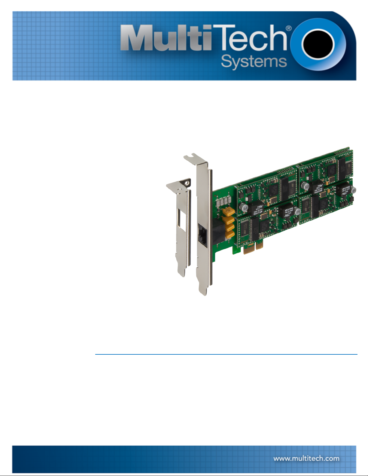
The MultiModem ISI server cards and modems provide four built-in V.92/56K modems on an industry-standard PCI
Express x1 architecture for analog dial-up or dedicated fax servers. It also offers V.34/33.6K Super G3 fax and Error
Correction Mode to reduce fax transmission time.
ISI Server Cards
The ISI9234HPCIE is a server modem expansion card that uses the PCI Express x1 architecture with four V.92
data/Super G3 fax modems. It allows you to add modems to communication servers and async host that have 32bit PCI bus architecture.
The ISI9234HPCIE has one RJ-45 connector that fans out to four RJ-11 connectors, one for each modem. The half
size card supports a high-speed interface up to 230 Kbps.
ISI Modems
ISI modems are compatible with the ITU-T V.92 protocol. They operate with downstream transmission speeds up
to 56 Kbps and upstream speeds up to 48 Kbps when connected to a V.92-compatible Internet service. The V.92
protocol sends data downstream at these speeds because data on the phone network is converted from digital to
analog only once before it reaches your modem.
Transmissions upstream and between client modems are limited to 33.6 Kbps. Downstream transmissions that are
converted more than once are also limited to 33.6 Kbps.
When calling an ISI modem with another V.92 modem over an analog phone line, the maximum speed is 33.6
Kbps. V.90 and V.92 connections are not possible when an analog line calls another analog line. When an ISI
modem connects an analog line to a digital line, the higher V.90/V.92 speeds are not available. If dialing a digital
line that supports V.90/V.92, the ISI modems can achieve the higher V.90/V.92 speeds.
Note: Line impairments, public phone infrastructure, and other external technological factors may prevent
connections from reaching the maximum 56 Kbps speed.
AT Commands
Use AT Commands to configure your ISI modems. In standard mode, store up to three command lines or phone
numbers of up to 40 characters each in nonvolatile memory. Modems can be set to support pulse and tone dialing
and can detect AT&T calling card tone. You can also configure for call progress detection, DTR dialing, remote
configuration, callback security, and limited TAM functions.
MultiModem®ISI ISI9234HPCIE Server Card User Guide 5
Page 6
PRODUCT OVERVIEW
Documentation
Download documentation from www.multitech.com/setup/product.go.
MultiModem ISI ISI9234HPCIE User Guide This document. Provides specifications, safety and
regulatory information, installation, and configuration
information (part number S000581).
MultiModem and SocketModem MT9234 AT Provides AT commands for configuring your device (part
Command Reference Guide number S000434).
Fax Overview Developer Guide Describes fax protocols, formats, compression, and
transmission (part number S0000265).
Fax Enhancements Describes V.34 Fax/Real-Time Fax Compression Conversion
V.92 modems (part number S0000279).
Fax Developer's Guide (Classes 1 and 1.0) Provides information and commands for using Fax Service
Class 1 and Class 1.0 (part number S0000262).
Fax Developer's Guide (Classes 2 and 2.0/2.1) Provides information and commands for using Fax Service
Class 2 and Class 2.0/2.1 (part number S0000239).
6 MultiModem®ISI ISI9234HPCIE Server Card User Guide
Page 7
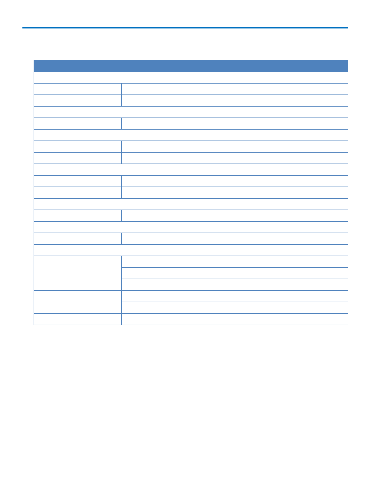
Specifications
Category Description
General
Bus Type PCI Express form factor 1x, PCIe 1.0 compatible.
Interrupt Request One IRQ per card (can be shared)
Speed
Baud Rates 300 bps to 230 Kbps per port
Physical Description
Weight 0.45 lbs. (200 g)
Dimensions See the topic, Dimensions.
Connectors and Cables
Connectors One RJ-45 jack
Cables One RJ-45 4-port fan-out cable
PRODUCT OVERVIEW
Environment
Operating Temperature 23° to 140° F (-5° to 60° C)
Power Requirements
Input Voltage 3.3V from PCIe interface
Certifications and Compliance
EMC Compliance FCC Part 15 Class B
EN55022 Class B
EN55024
Safety Compliance UL/cUL 60950-1 2nd Ed
IEC60950-1 2nd Ed am.1
Telecom Compliance 47CFR Part 68, CS03, TBR21
1
MultiModem®ISI ISI9234HPCIE Server Card User Guide 7
Page 8

PRODUCT OVERVIEW
Dimensions
Dimensions with Standard Bracket
8 MultiModem®ISI ISI9234HPCIE Server Card User Guide
Page 9
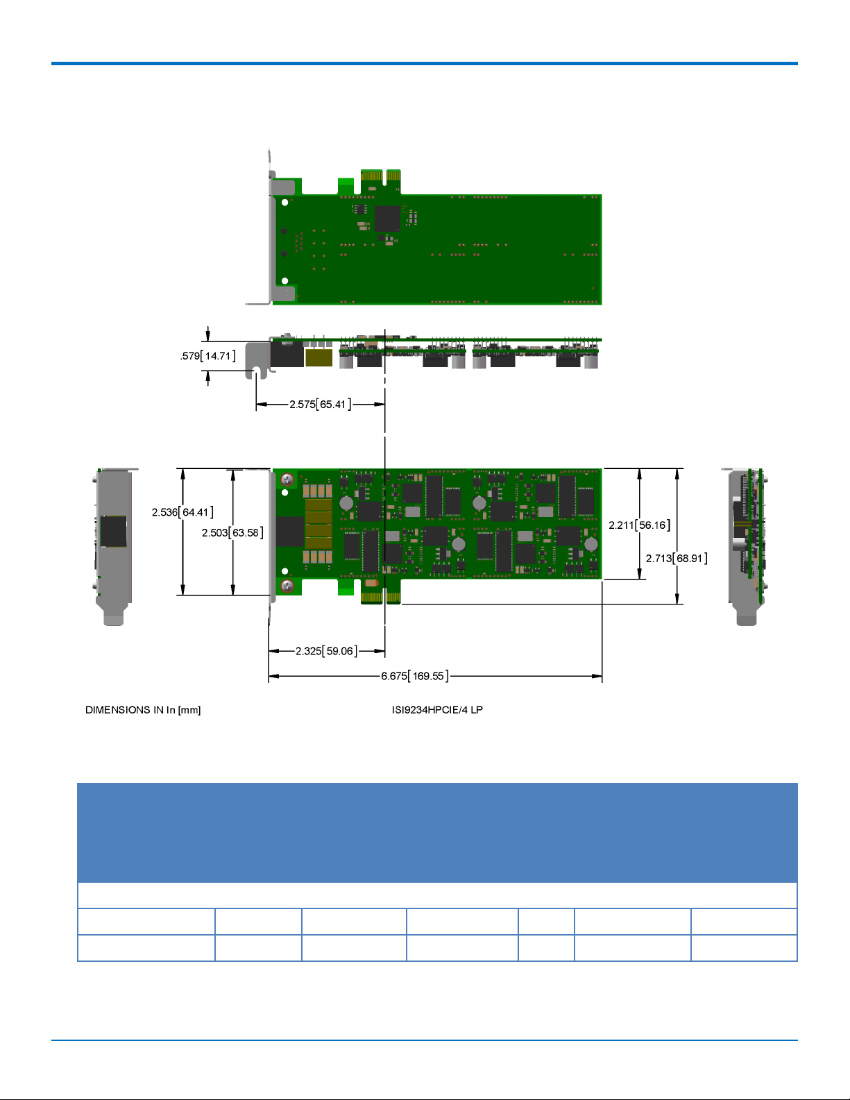
Dimensions with Low Profile Bracket
PRODUCT OVERVIEW
Power Measurements
Sleep Typical Maximum Peak Total Inrush Total Inrush
Charge Charge
measured in Duration
Millicoulombs during
(mC) Powerup
3.3 volts
Current (AMPS) 0.402 0.541 0.550 0.592 16.00 26mS
Watts 1.320 1.760 1.790
MultiModem®ISI ISI9234HPCIE Server Card User Guide 9
Page 10

SAFETY NOTICES
Safety Notices
Analog Telecom Safety Warnings
Before servicing, disconnect this product from its power source and telephone network. Also:
■ Never install telephone wiring during a lightning storm.
■ Never install a telephone jack in wet locations unless the jack is specifically designed for wet locations.
■ Use this product with UL and cUL listed computers only.
■ Never touch uninsulated telephone wires or terminals unless the telephone line has been disconnected at
the network interface.
■ Use caution when installing or modifying telephone lines.
■ Avoid using a telephone during an electrical storm. There may be a remote risk of electrical shock from
lightning.
■ Do not use a telephone in the vicinity of a gas leak.
CAUTION: To reduce the risk of fire, use only 26 AWG or larger UL Listed or CSA Certified telecommunication
Line cord.
Avertissement de sécurité télécom analogique
Avant de l'entretien, débrancher ce produit de son réseau d'alimentation et de téléphone. également:
■ Ne jamais installer du câblage téléphonique pendant un orage électrique.
■ Ne jamais installer de prises téléphoniques à des endroits mouillés à moins que la prise ne soit conçue pour
de tels emplacements.
■ Utilisez ce produit avec UL et cUL ordinateurs répertoriés seulement.
■ Ne jamais toucher fils ou des bornes téléphoniques non isolés à moins que la ligne téléphonique n'ait été
déconnectée au niveau de l'interface réseau.
■ Faire preuve de prudence au moment d'installer ou de modifier des lignes téléphoniques.
■ Éviter d'utiliser le télé phone pendant un orage électrique. Il peut y avoir un risque de choc électrique causé
par la foudre.
■ N'utilisez pas un téléphone à proximité d'une fuite de gaz.
Attention: Pour réduire les risques d’incendie, utiliser uniquement des conducteurs de télécommunications 26
AWG au de section supérleure.
10 MultiModem®ISI ISI9234HPCIE Server Card User Guide
Page 11

INSTALLING HARDWARE
Installing Hardware
Changing Mounting Brackets
To use the low profile bracket, remove the standard bracket and replace it with the low profile bracket.
Warning: Before handling the device, discharge any static in your body by touching a piece of grounded
metal such as the computer chassis. Electrostatic discharge (ESD) is the release of stored static electricity
that can damage electrical circuitry or components. Static electricity is often stored in your body and
discharged when you come in contact with an object of a different potential.
Attention: Perform the procedure described in this section only at an ESD workstation using an antistatic
wrist strap. If such a station is not available, you can provide some ESD protection by wearing an antistatic
wrist strap and attaching it to a metal ground screw (lug).
1. Carefully remove the ISI Card from its antistatic bag. Handle it only by the mounting bracket and edges.
Do not touch the gold-plated connectors along the bottom edge.
MultiModem®ISI ISI9234HPCIE Server Card User Guide 11
Page 12

INSTALLING HARDWARE
2. Remove the two screws holding the standard bracket to the device.
12 MultiModem®ISI ISI9234HPCIE Server Card User Guide
Page 13

3. Mount the low profile bracket using the screws you removed in Step 1.
INSTALLING HARDWARE
Installing Hardware
Note: Install the hardware, before installing drivers.
Warning: Before handling the device, discharge any static in your body by touching a piece of grounded
metal such as the computer chassis. Electrostatic discharge (ESD) is the release of stored static electricity
that can damage electrical circuitry or components. Static electricity is often stored in your body and
discharged when you come in contact with an object of a different potential.
MultiModem®ISI ISI9234HPCIE Server Card User Guide 13
Page 14

INSTALLING HARDWARE
Attention: Perform the procedure described in this section only at an ESD workstation using an antistatic
wrist strap. If such a station is not available, you can provide some ESD protection by wearing an antistatic
wrist strap and attaching it to a metal ground screw (lug).
To install the ISI card in your PCI-bus computer:
1. Turn off your computer, remove the power cord, and disconnect any peripheral devices.
2. Remove the computer's cover as instructed in your computer's manual.
3. Remove the slot cover for the unused PCI slot where you will install the ISI Card. Refer to your computer’s
manual for instructions on removing the slot cover.
4. If you did not swap the mounting bracket, carefully remove the ISI Card from its antistatic bag. Handle it
only by the mounting bracket and edges. Do not touch the gold-plated connectors along the bottom
edge.
5. Install the ISI Card into the selected expansion slot in the same manner as any other add-on card. Refer to
your computer’s manual for instructions on adding cards.
6. Fasten the retaining bracket to the computer chassis and replace cover on the computer.
7. Cable the card. The fan-out cable extends connections for four modems from the RJ-45 plug to four RJ-11
plugs.
a. Attach each RJ-11 plug to a phone line receptacle.
b. Attach the RJ-45 connector into the appropriate RJ45 receptacle on the ISI Server card.
14 MultiModem®ISI ISI9234HPCIE Server Card User Guide
Page 15

INSTALLING HARDWARE
Cable Diagrams
The ISI9234HPCIE uses a single fan-out cable to connect the four modems to four phone lines. The cable has an RJ45 connector on one end and four RJ-11 connectors on the other end. Use the RJ-11 connectors to connect to
phone lines.
MultiModem®ISI ISI9234HPCIE Server Card User Guide 15
Page 16

INSTALLING ON WINDOWS
Installing on Windows
The ISI9234HPCIE supports both 32-bit and 64-bit versions of the following Windows operating systems:
■ Windows Server 2003, 2008, and 2012
■ Windows 7, 8, Vista, and XP
For Linux support, refer to Installing on Linux.
Downloading Windows Drivers
Note: Drivers for all supported Windows operating systems are included in the same zip file.
To select the correct driver, you need to know if you have a 32-bit or 64-bit operating system. If you do not know,
check System information in the Windows Control Panel.
1. Go to www.multitech.com/setup/product.go and select your model from the Product drop down list.
2. Click Drivers and download the Windows driver.
3. Open the zip file and extract the files for your operating system to a folder in your Program directory.
Using the Windows Installer
Note: You need administrator rights to install the driver on your computer.
After you have installed the device in the PCIe slot on the computer's mother board, install the driver you
extracted:
1. Boot to the Windows operating system. If the Found New Hardware window appears, click Cancel to
close it.
2. Go to Driver's folder and double-click installdrvs.cmd to start the install.
3. Check Always trust software from "Multi-Tech Systems" and click Install to install the drivers.
Troubleshooting a Windows Installation
This topic describes troubleshooting for known installation issues.
Note: We recommend troubleshooting in Administrator mode.
Installations Did Not Install Four COM Ports or Modems
If the installation process did not install four COM ports or in the Device Manager, four modems:
1. In the Device Manager, run Scan for Hardware Changes.
2. Reboot the computer.
In the Device Manager, COM Port Numbers Do Not Match Hardware COM Ports
In Device Manager, Multi-Tech Communications Port (COMx), may show 5, 9, 14 and 15. When selecting the COM
Port properties it shows COM5, 6, 7 and 8.
Note: This issue appeared when installing on Windows 7 64bit, Windows 2008 64 bit or when installing with
the “installdrvs.cmd”.
16 MultiModem®ISI ISI9234HPCIE Server Card User Guide
Page 17

INSTALLING ON WINDOWS
To get the Communications port numbers to match COM ports:
1. In the Device Manager, go to Modems.
2. Right-click MultiTech Systems MT9234SMI #4 and select Uninstall.
3. On the Confirm Device Uninstall tab, check Delete the driver software for this device. ,if provided, and
select OK.
4. Repeat the uninstall for the remaining three modems.
5. In Device Manager go to Ports.
6. Right-click MultiTech Communications Port (COMx) and select Uninstall.
7. On the Confirm Device Uninstall tab, check Delete the driver software for this device. ,if provided, and
select OK
8. Repeat the uninstall for the remaining three COM ports.
9. Reboot the computer or Scan for Hardware changes so Windows can re-detect the COM ports and
modems.
10. Confirm that the MultiTech Communications Port (COMx) numbers matches the COM ports.
The installdrvs.cmd File Does Not work on XP or 2003
Only Windows Vista, 2008, 2012, 7 and 8 are supported.
MultiModem®ISI ISI9234HPCIE Server Card User Guide 17
Page 18

INSTALLING ON LINUX
Installing on Linux
Installing on Linux Kernel 3.5 and Higher
Note: The steps below were tested with Ubuntu 12.04 with Linux kernel 3.5.0 and may or may not work for
other 3.x.x versions.
After installing the ISI9234HPCIE in a PCIe slot:
1. Power up the computer and boot to Linux.
2. Go to www.multitech.com/setup/product.go and select your model from the Product drop down list.
3. Download the Linux driver, xr17v35x-lnx3.x.x-pak.zip, into a specified directory, such as /exar.
4. Start a terminal session and run command # cd /exar.
5. Run command # unzip xr17v35x-lnx3.x.x-pak.zip.
6. Find Makefile in the /exar, then execute command # make to compile the driver file, xr17v35x.ko.
7. Run command # insmod xr17v35x.ko to activate the module driver.
Note: This module registers Exar ports as “/dev/ttyXR0”, “/dev/ttyXR1”, etc.
8. Go to /lib/modules/(kernel version)/kernel/drivers and run command mkdir exar
9. Copy the xr17v35x.ko file into the exar folder /lib/modules/(kernel version)/kernel/drivers/exar.
10. Edit the /etc/modules file and add xr17v35x.
11. Run the command depmod.
12. Reboot Linux.
Linux device drivers and device should now be installed and activated.
To verify that the modules loaded, send the command lsmod
Installing Drivers on Linux Kernel 2.6.x
Note: The steps below were tested with Ubuntu and Linux kernel 2.6.32 and may or may not work for
other 2.x.x versions.
After installing the ISI9234HPCIE in a PCIe slot:
1. Power up the computer and boot to Linux.
2. Go to www.multitech.com/setup/product.go and select your model from the Product drop down list.
3. Download the Linux driver, xr17v35x-lnx3.x.x-pak.zip, into a specified directory, such as /exar.
4. Start a terminal session and run command # cd /exar.
5. Run command # unzip xr17v35x-lnx2.6.32-pak.zip.
6. Find Makefile in the /exar, then execute command # make to compile the driver file, xr17v35x.ko.
7. Run command # insmod xr17v35x.ko to activate the module driver.
Note: This module registers Exar ports as “/dev/ttyXR0”, “/dev/ttyXR1”, etc.
8. Go to /lib/modules/(kernel version)/kernel/drivers and run command mkdir exar
9. Copy the xr17v35x.ko file into the exar folder /lib/modules/(kernel version)/kernel/drivers/exar.
10. Edit the /etc/modules file and add xr17v35x.
18 MultiModem®ISI ISI9234HPCIE Server Card User Guide
Page 19

11. Run the command depmod.
12. Reboot Linux.
Linux device drivers and device should now be installed and activated.
To verify that the modules loaded, send the command lsmod
INSTALLING ON LINUX
MultiModem®ISI ISI9234HPCIE Server Card User Guide 19
Page 20

CONFIGURING MODEMS FOR YOUR COUNTRY
Configuring Modems for Your Country
Different countries have different regulations for modem operation. Before using your modems, you must
configure them for the country in which you are using them. For Windows computers, use the Global Wizard to set
the country. For Linux computers, use AT Commands to set the country.
Installing the Global Wizard
The Global Wizard utility works with the 32-bit and 64-bit versions of following Windows operating systems:
■ Windows Server 2003, 2008, and 2012
■ Windows 7, 8, Vista, and XP
1. Go to www.multitech.com/setup/product.go and select your model from the Product drop down list.
2. Click Software.
3. Click the Global Wizard link and run the Global Wizard installer.
4. Follow the on screen prompts and click Finish when installation is complete.
Using the Global Wizard
To set your country:
1. Run the Global Wizard, click Start > All Programs > Global Wizard > Global Wizard.
2. Click Next. The Global Wizard searches for your modems and identifies them.
3. Click Next and select a modem to configure.
4. Click Next and select the country in which the modem will be used.
5. Click Next and verify your choice of country. If it is correct, click Next to configure the modem.
6. Click Finish to exit.
7. If your device has multiple modems, repeat Steps 3 through 6 for each modem.
20 MultiModem®ISI ISI9234HPCIE Server Card User Guide
Page 21

CONFIGURING MODEMS FOR YOUR COUNTRY
Using AT Commands to Set Country
If not using Windows, use AT commands to configure the modem. A complete list of country and region codes is
available on the Multi-Tech site at www.multitech.com/global/configuration.go.
1. Run a communication program and open a terminal window.
2. Type AT%T19,0,nn, where nn is the country/region code in hexadecimal format, press ENTER. OK
appears.
3. Type ATI9 and press ENTER to verify the change.
The country code displays in decimal format, as in this example:
Country/Region AT Command Country code
(hexadecimal) (decimal)
Euro/NAM AT%T19,0,34 (default) 52
MultiModem®ISI ISI9234HPCIE Server Card User Guide 21
Page 22

REGULATORY INFORMATION
Regulatory Information
47 CFR Part 68 Telecom
1. This equipment complies with Part 68 of the 47 CFR rules and the requirements adopted by the ACTA.
Located on this equipment is a label that contains, among other information, the registration number and
Ringer Equivalence Number (REN) for this equipment or a product identifier in the format:
For current products: US:AAAEQ##Txxxx.
For legacy products: AU7USA-xxxxx-xx-x
If requested, this number must be provided to the telephone company.
2. A plug and jack used to connect this equipment to the premises wiring and telephone network must
comply with the applicable 47 CFR Part 68 rules and requirements adopted by the ACTA. It’s designed to
be connected to a compatible modular jack that is also compliant.
3. The Ringer Equivalence Number (REN) is used to determine the number of devices that may be
connected to a telephone line. Excessive RENs on a telephone line may result in the devices not ringing in
response to an incoming call. In most but not all areas, the sum of RENs should not exceed five (5.0). To
be certain of the number of devices that may be connected to a line, as determined by the total RENs,
contact the local telephone company. For products approved after July 23, 2001, the REN for this product
is part of the product identifier that has the format US:AAAEQ##Txxxx. The digits represented by ## are
the REN without a decimal point (e.g., 03 is a REN of 0.3). For earlier products, the REN is separately
shown on the label.
4. If this equipment causes harm to the telephone network, the telephone company will notify you in
advance that temporary discontinuance of service may be required. But if advance notice isn't practical,
the telephone company will notify the customer as soon as possible. Also, you will be advised of your
right to file a complaint with the FCC if you believe it is necessary.
5. The telephone company may make changes in its facilities, equipment, operations or procedures that
could affect the operation of the equipment. If this happens, the telephone company will provide
advance notice in order for you to make necessary modifications to maintain uninterrupted service.
6. If trouble is experienced with this equipment, please contact Multi-Tech Systems, Inc. at the address
shown below for details of how to have the repairs made. If the equipment is causing harm to the
telephone network, the telephone company may request that you disconnect the equipment until the
problem is resolved.
7. Connection to party line service is subject to state tariffs. Contact the state public utility commission,
public service commission or corporation commission for information.
8. No repairs are to be made by you. Repairs are to be made only by Multi-Tech Systems or its licensees.
Unauthorized repairs void registration and warranty.
9. If your home has specially wired alarm equipment connected to the telephone line, ensure the
installation of this equipment does not disable your alarm equipment. If you have questions about what
will disable alarm equipment, consult your telephone company or a qualified installer.
10. Connection to party line service is subject to state tariffs. Contact the state public utility commission,
public service commission or corporation commission for information.
11. This equipment is hearing aid compatible.
12. Manufacturing Information on telecommunications device (modem):
Manufacturer: Multi-Tech Systems
22 MultiModem®ISI ISI9234HPCIE Server Card User Guide
Page 23

REGULATORY INFORMATION
Trade Name: SocketModem
Model Number: MT9234SMI
Registration Number: US:AU7MM01BMT9234SMI
Ringer Equivalence: 0.1B
Modular Jack (USOC): RJ11C or RJ11W (single line)
Service Center in USA: Multi-Tech Systems, Inc.
2205 Woodale Drive
Mounds View, MN 55112 USA
(763)785-3500
(763) 785-9874 (Fax)
47 CFR Part 15 Regulation Class B Devices
This equipment has been tested and found to comply with the limits for a Class B digital device, pursuant to part
15 of the FCC Rules. These limits are designed to provide reasonable protection against harmful interference in a
residential installation. This equipment generates, uses, and can radiate radio frequency energy and, if not installed
and used in accordance with the instructions, may cause harmful interference to radio communications. However,
there is no guarantee that interference will not occur in a particular installation. If this equipment does cause
harmful interference to radio or television reception, which can be determined by turning the equipment off and
on, the user is encouraged to try to correct the interference by one or more of the following measures:
■ Reorient or relocate the receiving antenna.
■ Increase the separation between the equipment and receiver.
■ Connect the equipment into an outlet on a circuit different from that to which the receiver is connected.
■ Consult the dealer or an experienced radio/TV technician for help.
Warning: Changes or modifications to this unit not expressly approved by the party responsible for compliance
could void the user’s authority to operate the equipment.
EMC, Safety, and R&TTE Directive Compliance
The CE mark is affixed to this product to confirm compliance with the following European Community Directives:
Council Directive 2004/108/EC of 15 December 2004 on the approximation of the laws of Member States
relating to electromagnetic compatibility;
and
Council Directive 2006/95/EC of 12 December 2006 on the harmonization of the laws of Member States
relating to electrical equipment designed for use within certain voltage limits;
and
Council Directive 1999/5/EC of 9 March 1999 on radio equipment and telecommunications terminal
equipment and the mutual recognition of their conformity.
MultiModem®ISI ISI9234HPCIE Server Card User Guide 23
Page 24

ENVIRONMENTAL INFORMATION
Environmental Information
Waste Electrical and Electronic Equipment Statement
WEEE Directive
The WEEE Directive places an obligation on EU-based manufacturers, distributors, retailers, and importers to takeback electronics products at the end of their useful life. A sister directive, ROHS (Restriction of Hazardous
Substances) complements the WEEE Directive by banning the presence of specific hazardous substances in the
products at the design phase. The WEEE Directive covers all Multi-Tech products imported into the EU as of August
13, 2005. EU-based manufacturers, distributors, retailers and importers are obliged to finance the costs of recovery
from municipal collection points, reuse, and recycling of specified percentages per the WEEE requirements.
Instructions for Disposal of WEEE by Users in the European Union
The symbol shown below is on the product or on its packaging, which indicates that this product must not be
disposed of with other waste. Instead, it is the user's responsibility to dispose of their waste equipment by handing
it over to a designated collection point for the recycling of waste electrical and electronic equipment. The separate
collection and recycling of your waste equipment at the time of disposal will help to conserve natural resources
and ensure that it is recycled in a manner that protects human health and the environment. For more information
about where you can drop off your waste equipment for recycling, please contact your local city office, your
household waste disposal service or where you purchased the product.
July, 2005
24 MultiModem®ISI ISI9234HPCIE Server Card User Guide
Page 25

ENVIRONMENTAL INFORMATION
REACH Statement
Registration of Substances
After careful review of the legislation and specifically the definition of an “article” as defined in EC Regulation
1907/2006, Title II, Chapter 1, Article 7.1(a)(b), it is our current view Multi-Tech Systems, Inc. products would be
considered as “articles”. In light of the definition in § 7.1(b) which requires registration of an article only if it
contains a regulated substance that “is intended to be released under normal or reasonably foreseeable conditions
of use,” Our analysis is that Multi-Tech Systems, Inc. products constitute nonregisterable articles for their intended
and anticipated use.
Substances of Very High Concern (SVHC)
Per the candidate list of Substances of Very High Concern (SVHC) published October 28, 2008 we have reviewed
these substances and certify the Multi-Tech Systems, Inc. products are compliant per the EU “REACH”
requirements of less than 0.1% (w/w) for each substance. If new SVHC candidates are published by the European
Chemicals Agency, and relevant substances have been confirmed, that exceeds greater than 0.1% (w/w), MultiTech Systems, Inc. will provide updated compliance status.
Multi-Tech Systems, Inc. also declares it has been duly diligent in ensuring that the products supplied are compliant
through a formalized process which includes collection and validation of materials declarations and selective
materials analysis where appropriate. This data is controlled as part of a formal quality system and will be made
available upon request.
MultiModem®ISI ISI9234HPCIE Server Card User Guide 25
Page 26

ENVIRONMENTAL INFORMATION
Restriction of the Use of Hazardous Substances (RoHS)
Multi-Tech Systems, Inc
Certificate of Compliance
2011/65/EU
Multi-Tech Systems confirms that its embedded products comply with the chemical concentration limitations set
forth in the directive 2011/65/EU of the European Parliament (Restriction of the use of certain Hazardous
Substances in electrical and electronic equipment - RoHS).
These Multi-Tech products do not contain the following banned chemicals1:
■ Lead, [Pb] < 1000 PPM
■ Mercury, [Hg] < 1000 PPM
■ Hexavalent Chromium, [Cr+6] < 1000 PPM
■ Cadmium, [Cd] < 100 PPM
■ Polybrominated Biphenyl, [PBB] < 1000 PPM
■ Polybrominated Diphenyl Ether, [PBDE] < 1000 PPM
Environmental considerations:
■ Moisture Sensitivity Level (MSL) =1
■ Maximum Soldering temperature = 260C (in SMT reflow oven)
1
Lead usage in some components is exempted by the following RoHS annex, therefore higher lead concentration
would be found in some modules (>1000 PPM);
- Resistors containing lead in a glass or ceramic matrix compound.
26 MultiModem®ISI ISI9234HPCIE Server Card User Guide
Page 27

ENVIRONMENTAL INFORMATION
Information on HS/TS Substances According to Chinese Standards
In accordance with China's Administrative Measures on the Control of Pollution Caused by Electronic Information
Products (EIP) # 39, also known as China RoHS, the following information is provided regarding the names and
concentration levels of Toxic Substances (TS) or Hazardous Substances (HS) which may be contained in Multi-Tech
Systems Inc. products relative to the EIP standards set by China's Ministry of Information Industry (MII).
Hazardous/Toxic Substance/Elements
Name of the Component Lead Mercury Cadmium Hexavalent Polybromi Polybrominat
(PB) (Hg) (CD) Chromium nated ed Diphenyl
(CR6+) Biphenyl Ether (PBDE)
(PBB)
Printed Circuit Boards O O O O O O
Resistors X O O O O O
Capacitors X O O O O O
Ferrite Beads O O O O O O
Relays/Opticals O O O O O O
ICs O O O O O O
Diodes/ Transistors O O O O O O
Oscillators and Crystals X O O O O O
Regulator O O O O O O
Voltage Sensor O O O O O O
Transformer O O O O O O
Speaker O O O O O O
Connectors O O O O O O
LEDs O O O O O O
Screws, Nuts, and other X O O O O O
Hardware
AC-DC Power Supplies O O O O O O
Software /Documentation CDs O O O O O O
Booklets and Paperwork O O O O O O
Chassis O O O O O O
X Represents that the concentration of such hazardous/toxic substance in all the units of homogeneous
material of such component is higher than the SJ/Txxx-2006 Requirements for Concentration Limits.
O Represents that no such substances are used or that the concentration is within the aforementioned limits.
MultiModem®ISI ISI9234HPCIE Server Card User Guide 27
Page 28

ENVIRONMENTAL INFORMATION
Information on HS/TS Substances According to Chinese Standards (in Chinese)
依依照照中中国国标标准准的的有有毒毒有有害害物物质质信信息息
根据中华人民共和国信息产业部 (MII) 制定的电子信息产品 (EIP) 标准-中华人民共和国《电子信息产品污染
控制管理办法》(第 39 号),也称作中国 RoHS, 下表列出了 Multi-Tech Systems, Inc. 产品中可能含有的有毒
物质 (TS) 或有害物质 (HS) 的名称及含量水平方面的信息。
有有害害//有有毒毒物物质质//元元素素
成成分分名名称称
印刷电路板
电阻器
电容器
铁氧体磁环
继电器/光学部件
ICs O O O O O O
二极管/晶体管
振荡器和晶振
调节器
电压传感器
变压器
扬声器
连接器
LEDs O O O O O O
铅铅 (PB) 汞汞 (Hg) 镉镉 (CD) 六六价价铬铬 (CR6+)
O O O O O O
X O O O O O
X O O O O O
O O O O O O
O O O O O OO
O O O O O O
X O O O O O
O O O O O O
O O O O O O
O O O O O O
O O O O O O
O O O O O O
多多溴溴联联苯苯 多多溴溴二二苯苯醚醚
(PBB) (PBDE)
螺丝、螺母以及其它五金件
交流-直流电源
软件/文档 CD
手册和纸页
底盘
X 表示所有使用类似材料的设备中有害/有毒物质的含量水平高于 SJ/Txxx-2006 限量要求。
O 表示不含该物质或者该物质的含量水平在上述限量要求之内。
28 MultiModem®ISI ISI9234HPCIE Server Card User Guide
X O O O O O
O O O O O O
O O O O O O
O O O O O O
O O O O O O
 Loading...