

Multitech ISI9234PCIE, ISI5634UPCI, ISI9234PCIE-4, ISI9234PCIE-8, ISI5634UPCI-4 User Manual
...Page 1

Intelligent Serial Interface
Server Cards
ISI5634UPCI & ISI9234PCIE
User Guide
Page 2

User Guide
P/N S000442C, Revision C
Models ISI9234PCIE-4 & ISI9234PCIE-8
Models ISI5634UPCI-4 & ISI5634UPCI-8
This publication may not be reproduced, in whole or in part, witho ut prior expressed written permission from
Multi-Tech Systems, Inc. All rights reserved.
Copyright © 2008 by Multi-Tech Systems, Inc.
Multi-Tech Systems, Inc. makes no representation or warranties with respect to the contents hereof and specifically
disclaims any implied warranties of merchantability or fitness for any particular purpose. Furthermore, Multi-Tech
Systems, Inc. reserves the right to revise this publication and to make changes from time to time in the content
hereof without obligation of Multi-Tech Systems, Inc. to notify any person or organization of such revisions or
changes.
Record of Revision
Revision Date Description
A 10/24/07 Manual released. All pages at Revision A.
B 04/14/08 Remove ISI Management Software and replace with Reset Utility.
C 06/06/08 Remove ISI4604/8 Serial Cards, add procedures for Windows Server 2008 32-bit
and 64-bit driver installation, and change Windows XP, 2003, and 2000 driver
installation procedures.
Trademarks
MultiModem,
Multi-Tech, and the Multi-Tech logo are trademarks of Multi-Tech Systems, Inc.
Microsoft, Windows 2000, 2003, XP, Vista, and Windows Server 2008 are registered trademarks or trademarks of
Microsoft Corporation in the United States and/or other countries.
Patents
This devi
ce covered by one or more of the following patents: 6,031,867; 6,012,113; 6,009,082; 5,905,794; 5,864,560;
5,815,567; 5,815,503; 5,812,534; 5,809,068; 5,790,532; 5,764,628; 5,764,627; 5,754,589; 5,724,356; 5,673,268;
5,673,257; 5,644,594; 5,628,030; 5,619,508; 5,617,423; 5,600,649; 5,592,586; 5,577,041; 5,574,725; 5,559,793;
5,546,448; 5,546,395; 5,535,204; 5,500,859; 5,471,470; 5,463,616; 5,453,986; 5,452,289; 5,450,425; D353, 598;
5,355,365; 5,309,562; 5,301,274;
7082106;7082141;7092406. Ot h e r Patents Pending
World Headquarters
Mult
i-Tech Systems, Inc.
2205 Woodale Drive
Mounds View, Minnesota 55112
Phone: 763-785-3500 or 800-328-9717
Fax: 763-785-9874
Technical Support
Country By Email By Phone
e, Middle East, Africa: support@multitech.co.uk +(44) 118 959 7774
Europ
U.S., Canada, all others: support@multitech.com (800) 972-2439 or (763) 717-5863
Internet Address: http://www.multitech.com
2
Page 3

Table of contents
Contents
Chapter 1—Introduction and Description ................................................................................................................ 4
How to Use This Manual ........................................................................................................................................... 4
Introduction to ISI Server Cards ................................................................................................................................ 4
ISI Modems ............................................................................................................................................................... 4
ISI Reset Utility .......................................................................................................................................................... 5
Technical Specifications ............................................................................................................................................ 6
Computer Requirements ........................................................................................................................................ 6
Mechanical Electrical Environmental ..................................................................................................................... 6
Chapter 2—Hardware Installation ............................................................................................................................. 7
Introduction ................................................................................................................................................................ 7
Safety Warnings ........................................................................................................................................................ 7
Hardware Installation Procedures ............................................................................................................................. 7
Chapter 3—Software Installation .............................................................................................................................. 9
Introduction ................................................................................................................................................................ 9
Driver Installation for Windows Server 2008 and Vista ...................................................................................... 10
Installation of the Communications Port .............................................................................................................. 12
Un-Installing ISI Drivers ....................................................................................................................................... 17
Delete Modem Drivers. ........................................................................................................................................ 18
Delete COM Ports. ............................................................................................................................................... 19
Driver Installation for Windows XP/2003/2000 ........................................................................................................ 22
Card Driver Installation. ....................................................................................................................................... 22
Modem Driver Installation. ................................................................................................................................... 27
Un-Installing ISI Drivers ....................................................................................................................................... 30
Delete Modem Drivers. ........................................................................................................................................ 30
Delete COM Ports. ............................................................................................................................................... 32
Installing the ISI Driver in Linux ............................................................................................................................... 35
Linux Driver Installation Overview ....................................................................................................................... 35
Building the Linux Driver ...................................................................................................................................... 35
Creating Linux TTY Device Names ..................................................................................................................... 36
Verifying Successful Loading of the Linux Driver ................................................................................................ 36
Un-Installing the Linux ISI Driver ......................................................................................................................... 36
Configuring your Modems for your Country ............................................................................................................ 37
Chapter 4 – Reset Utility ........................................................................................................................................... 38
Chapter 5 - Warranty, Service, & Tech Support ..................................................................................................... 39
Multi-Tech Warranty Statement............................................................................................................................... 39
Repair Procedures for U.S. and Canadian Customers ....................................................................................... 39
Repair Procedures for International Customers (Outside U.S.A. and Canada) .................................................. 39
Repair Procedures for International Distributors ................................................................................................. 40
Replacement Parts .............................................................................................................................................. 40
Software User License Agreement ...................................................................................................................... 41
On-Line Warranty Registration ............................................................................................................................ 41
Appendices ................................................................................................................................................................ 42
Appendix A— Cable Wiring Diagrams .................................................................................................................... 42
Appendix B—Regulatory Information ...................................................................................................................... 43
Appendix C - Waste Electrical and Electronic Equipment (WEEE) Statement ....................................................... 44
Appendix D – C-ROHS HT/TS Substance Concentration ...................................................................................... 45
3
Page 4
Chapter 1 – Introduction and Description
Chapter 1—Introduction and Description
How to Use This Manual
This manual describes the Multi-Tech Intelligent Serial Interface, Server Cards Models ISI5634UPCI-4/8 and
ISI9234PCIE-4/8. The UPCI Cards install on a Universal PCI-bus architecture and the PCI Express cards install on
a PCI Express-bus architecture.
We assume that you have basic PC skills. Therefore, we have not inclu ded st ep-by- step instr uction s for basic
computer operations.
Introduction to ISI Server Cards
The ISI Server Cards, model ISI5634UPCI is a Universal PCI-bus architecture and the ISI9234PCIE is a PCI Expressbus architecture. The -4 ISI Server card is a server modem expansion card with four V.92 data/Super G3 fax modems.
The -8 ISI Server card is an expansion card with eight such modems. These excellent hardware products add
modems to communication servers and async hosts that have 32-bit PCI bus architecture.
®
The ISI Server Cards ship with drivers for the following multiuser operating systems: Windows
Advanced Server, Windows 2000 Professional, Windows 2003, Windows XP, Windows Vista, Windows Server
and Linux kernel 2.4.x.
The ISI Server Cards can be combined to support asynchronous serial devices (local or dial-up). The ports can be
used to connect basic terminals (with or without multiple pages of memory) to multiplexer ch annels and
asynchronous modems. Each port can support as many screens as there are physical pages of memory on the
terminal. In Windows 2000/2003/XP/Vista/2008, a built-in autodetect utility enables detection of Multi-Tech
modems and sets the proper initialization strings.
2000 Server and
®
2008,
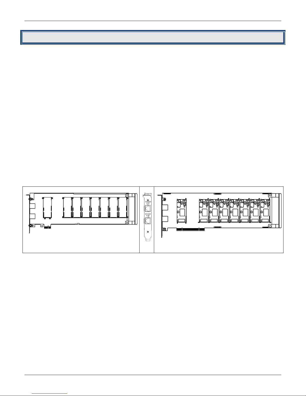
ISI9234PCI Express Card
The -4 server card has one RJ-45 connector that fans out to four RJ-11 connectors, one for each of its modems.
Simi l a r l y, the - 8 s erver c a r d has two RJ-45 connectors that fan out to eight RJ-11 connectors, one for each of its
modems. Both server cards are full size add-on cards that support a high-speed interface up to 230 Kbps.
ISI5634UPCI Card
ISI Modems
The ISI modems are compatible with the ITU-T V.92 protocol. They make quick connections and operate at
downstream transmission speeds of up to 56K bps and upstream transmission speeds of up to 48K bps when
connected to V.92-compatible Internet Service Providers . The V.92 protocol can send data d ownstream from the
Internet to your computer at these speeds because data on the telephone network typically is converted from
digital to analog only once before it reaches your modem. Upstream transmissions and transmissions between
client modems are limited to 33.6Kbps.
Upstream transmissions to non-V.92-compatible ISPs and downstream transmissions that are con verted more than
once on the telephone line are also limited to 33.6K bps.
When calling into the ISI modem with another V92 modem over an analog phone line, the maximum speed
achievable is 33.6 Kbps. V90 or V92 connections are not possible when an a nalog line is calling another
analog line. Similarly, when the ISI modem is involved in a call b etween an analog line and a digital line, the higher
V.90/V.92 speeds cannot be used. However, ISI modems can achieve the higher V.90/V.92 spe eds when
dialingoutto a digital phone line that supports V.90/V.92.
4
Page 5

Chapter 1 – Introduction and Description
Note: Th o u g h t h e s e m o d em s a r e ca p a b l e of 5 6 K b ps download performance, line impairments,
public telephone infrastructure flaws, and other external technological factors currently prevent
connections from reaching this maximum 56Kbps speed.
Modems on the ISI Card are Plug and Play capable with interactive automatic dialing and command mode
configuration. In standard mode, you can store up to three command lines or telephone numbers of up to 40
characters each in the modems' nonvolatile memo r y. T he modems can d ial using puls es or tones and can
recognize dial tones and busy signals for reliable call-progress detection. The modems can detect AT&T calling
card tones. They also have DTR dialing, remote configuration, and 11-bit capabilities, and they incorporate selfresetting lightning protection. Serial port speeds can be set as high as 230,400 bps. They are both FCC
registered for connection without notification to the telephone company.
The ISI Card has full-duplex intelligent modems with V.42 error correction, V.42bi s , and V.44 d a ta com pressi on. Th e
ISI modems support "Super G3" ITU-T V.34 fax communications at speeds up to 33.6Kbps with Class 2.1 fax
commands. The ISI modems also support voice functionality (+V commands).
ISI Reset Utility
MultiTech's ISI Reset Utility is shipped with each ISI Card. It allows you to reset the modems associated with the
ISI Card in a computer running either Windows 2000 Professional, Windows 2000 Server, Windows 2000 Advanced
Server, Windows 2003, Windows XP, Windows Vista, and Windows Server 2008.
5
Page 6

Chapter 1 – Introduction and Description
Technical Specifications
Computer Requirements
• Pentium®- based PC
• Microsoft Windows 2003, Windows XP, Windows 2000 Professional, Windows 2000 Server and
Advanced Server, Windows Vista, Windows 2008, or Linux (kernel 2.4.x).
• a CD-ROM drive (or, if software/drivers have been downloaded, a floppy drive)
• 2M bytes of hard disk space
Mechanical Electrical Environmental
• D i m e n s i o n s : 1 3 . 2 5 " x 4 . 2 " 33.66 cmx 10.67cm
• Baud Rates: 300 bps to 230 Kbps per port
• Bus Type: PCI Express form factor.
Compatible with PCI spec version 2.1 or higher.
• Connectors: one RJ-45 jack (female) on ISI-4; two RJ-45 jacks (female) on ISI-8
• Cables: The ISI-8 is shipped with two four-port fan-out cables. Each cable has an RJ-45 plug (male) at
one end and four RJ-11 plugs (male) at the other end. The ISI-4 is shipped with one such four-port fanout cable.
• Temperature: 32° to 120°F (0° to 50°C)
• Power: 250 milliamps @ +5vDC (8 ports; ISI5634UPCI-8)
1 .75A @3.3v DC (8 ports; ISI5634UPCI-8)
130 milliamps @ +5v DC (4 ports; ISI5634UPCI-4)
885 milliamps @3.3v DC (4 ports; ISI5634UPCI-4)
700 milliamps @3.3v DC (4 ports; ISI9234PCIE-4)
1.20A @3.3v DC (8 ports; ISI9234PCIE-8)
• Interrupt Request (IRQ): One IRQ per card (can be shared)
• Warranty: Two years
Manufactured in Mounds View, MN, U.S.A.
6
Page 7
Chapter 2 – Hardware Installation
Chapter 2—Hardware Installation
Introduction
This chapter describes installation of the Multi-Tech ISI as an expansion card in your PCI-bus computer.
Safety Warnings
• This product must be installed by a qualified service person.
• When installing or servicing this product, the phone lines must be disconnected to remove the risk of
hazardous voltages.
• Never install telephone wiring during a lightning storm.
• Never install telephone jacks in wet locations unless the jack is specifically designed for wet locations.
• This product is to be used with UL and CUL listed computers.
• Never touch uninsulated telephone wires or terminals unless the telephone line has been disconnected at
the network interface.
• Use caution when installing or modifying telephone lines.
• Avoid using a telephone (other than a cordless type) during an electrical storm. There may be a remote risk
of electrical shock from lightning.
• Do not use the telephone to report a gas leak in the vicinity of the leak.
Hardware Installation Procedures
To install the ISI Card into your PCI-bus computer, follow the steps presented below.
1. Turn off your computer and any peripheral equipment connected to it. The ISI Card can be installed in a
Pentium equivalent PCI bus computer.
2. Remove the cover of your computer as instructed in your computer's documentation.
3. Before handling the ISI Card, discharge any static in your body by touching a piece of grounded metal
such as the computer chassis.
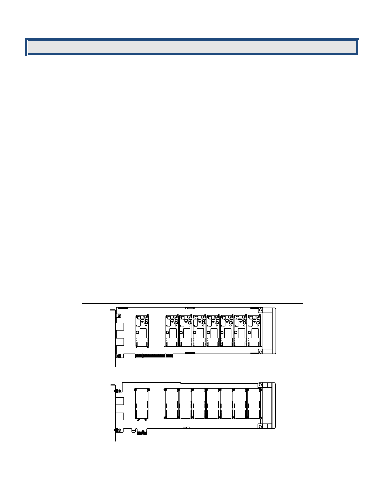
4. Carefully remov e the IS I Ca rd fr om its a nt is ta tic bag, handling it only by the mounting bracket and edges.
Do not touch the gold-plated connectors along the bottom edge. (You may want to save packaging for
possible future use.)
ISI5634UPCI-8
ISI9234PCIE-8
7
Page 8
Chapter 2 – Hardware Installation
5. Locate the unused PCI slot you will be using for your ISI Card and remove the slot cover according to
instructions in your computer's
6. Install the ISI Card into the selected expansion slot in the same manner as any other add-on card, as
instructed in your computer’s documentation.
7. Fasten the retaining bracket to the computer chassis and replace cover on the computer.
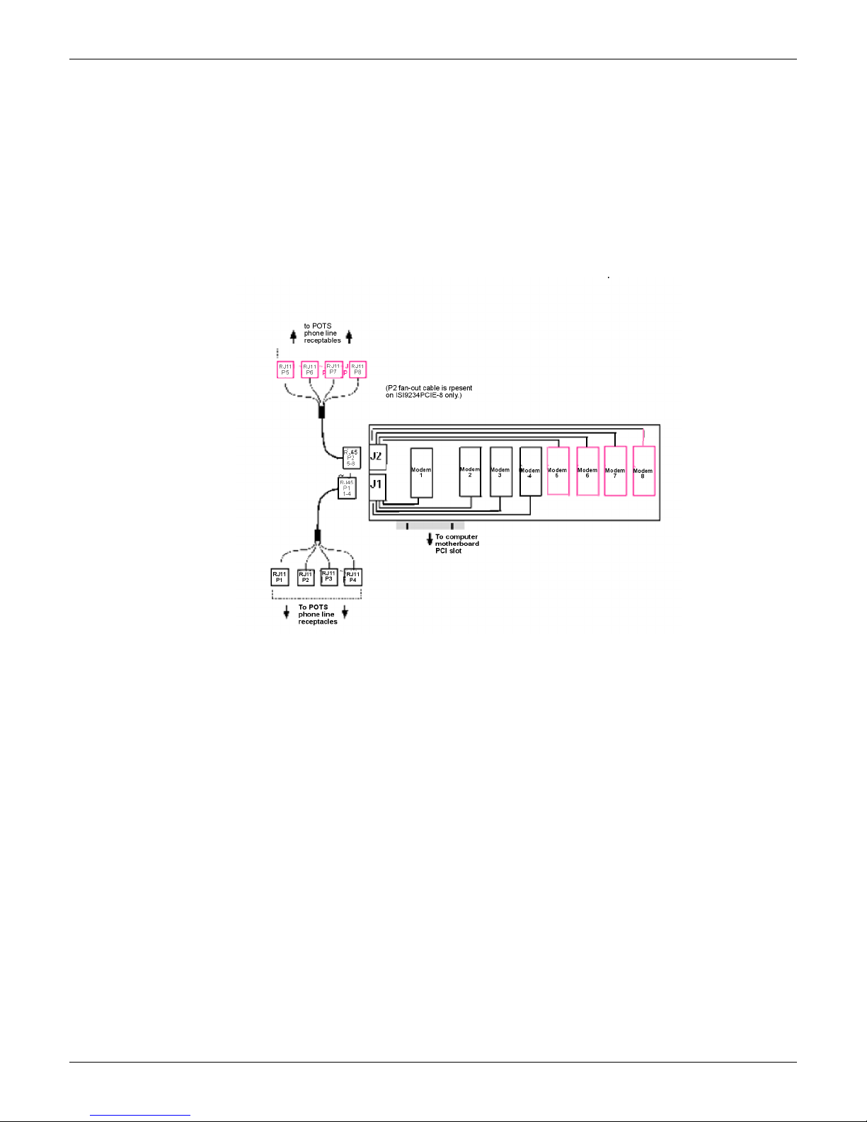
8. Cabling.
The -4 ISI Server card has one RJ-45 receptacle and one fan-out cable; the -8 ISI Server
card has two RJ-45 receptacles and two fan-out cables. Each fan-out cable extends connections for
four modems from the RJ-45 plug to four RJ-11 plugs. Each RJ-11 plug should then be attached to a
phone line receptacle. Attach the RJ-45 connector into the appropriate RJ45 receptacle on the ISI
Server card.
To vi e w a p i n o u t d i a g r a m o f t h e I S I S e r v er Car d Fan-Ou t Cabl e s , s ee Appendix A of this manual.
Fan-Out Cable for ISI Server Card
8
Page 9

Chapter 3 – Software Installation
Chapter 3—Software Installation
Introduction
The ISI Cards ship with drivers and software for each of the following operating systems: Windows Server® 2008,
Windows
ISI5634-UPCI and the ISI9234-PCI Express products. This chapter describes the installation of these drivers. You
may need to configure the modems for your country/region, the procedure for doing this is at the end of this
chapter. The installation and use of the Reset Utility is described in Chapter 4.
Installing a device driver modifies your system. For this reason, only the super user (system administrator) is
allowed to perform the installation. If you cannot login as administrator, find the person in your organization with
this authorization (i.e., password). To begin driver installation, login as administrator. Then proceed with the
appropriate installation section in this chapter.
Windows Drivers: The MultiModem product driver must be installed in your computer’s program directory. The
Windows drivers are located on the MultiModem product CD in the Drivers I Windows Drivers folder. A complete
set of drivers for each operating system is organized into Vista and XP with either 32-bit or 64-bit processor. Most
users will select either the 32-bit Vista or 32-bit XP drivers. Windows 2000 users must select the drivers from the
Drivers I Windows_2000 directory. Server users can select either 32-bit or 64-bit depending on their application.
For server users to determine whether they have a 32-bit or 64-bit operating system, go to Start I All Programs I
Accessories I System Tools I Computer and click on the System Properties button. Under System you will see
System Type: 64-bit Operating System.
®
Vista, XP, 2003, 2000 Server, 2000 Advanced Server, and Linux. The ISI drivers are the same for the
Linux Drivers : Linux Operating System drivers are also located on the CD in the Drivers I Linux Folder. Refer to
the Readme file (also in the Linux directory) for the correct driver file and installation guide for your
distribution/version of Linux.
Overview of Windows Driver Installation: Three install wizards guide you through the software Installation in this
order:
Part A installs the USB Driver.
Part B associates the PC port with the USB Driver, and finally
Part C installs the modem driver.
9
Page 10
Chapter 3 – Software Installation
Driver Installation for Windows Server 2008 and Vista
The following driver installation procedure is based on Windows Server 2008 64-bit Operating System. The
procedure may vary slightly for the Windows Server 2008 32-bit Operating System and Vista.
Card Driver Installation
1. Power up your computer.
2. Windows Server 2008 will detect the ISI Card. A screen from the tray area, at the bottom right of the
screen will appear briefly Installing Device Driver Software.
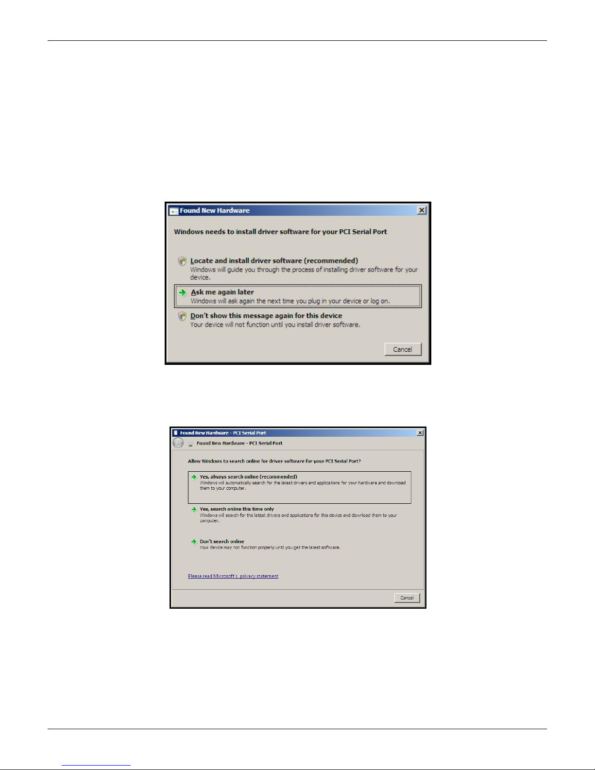
3. The Found New Hardware screen appears for Windows to install driver software for your PCI Serial
Port.
Click on Locate and install driver software (recommended). Wi ndows will guide you through the
process of installing driver software for your device.
4. A Found New Hardware – PCI Serial Port screen appears and asks: Allow Windows to search
online for driver software for your PCI Serial Port?
Select Don’t search online.
10
Page 11
Chapter 3 – Software Installation
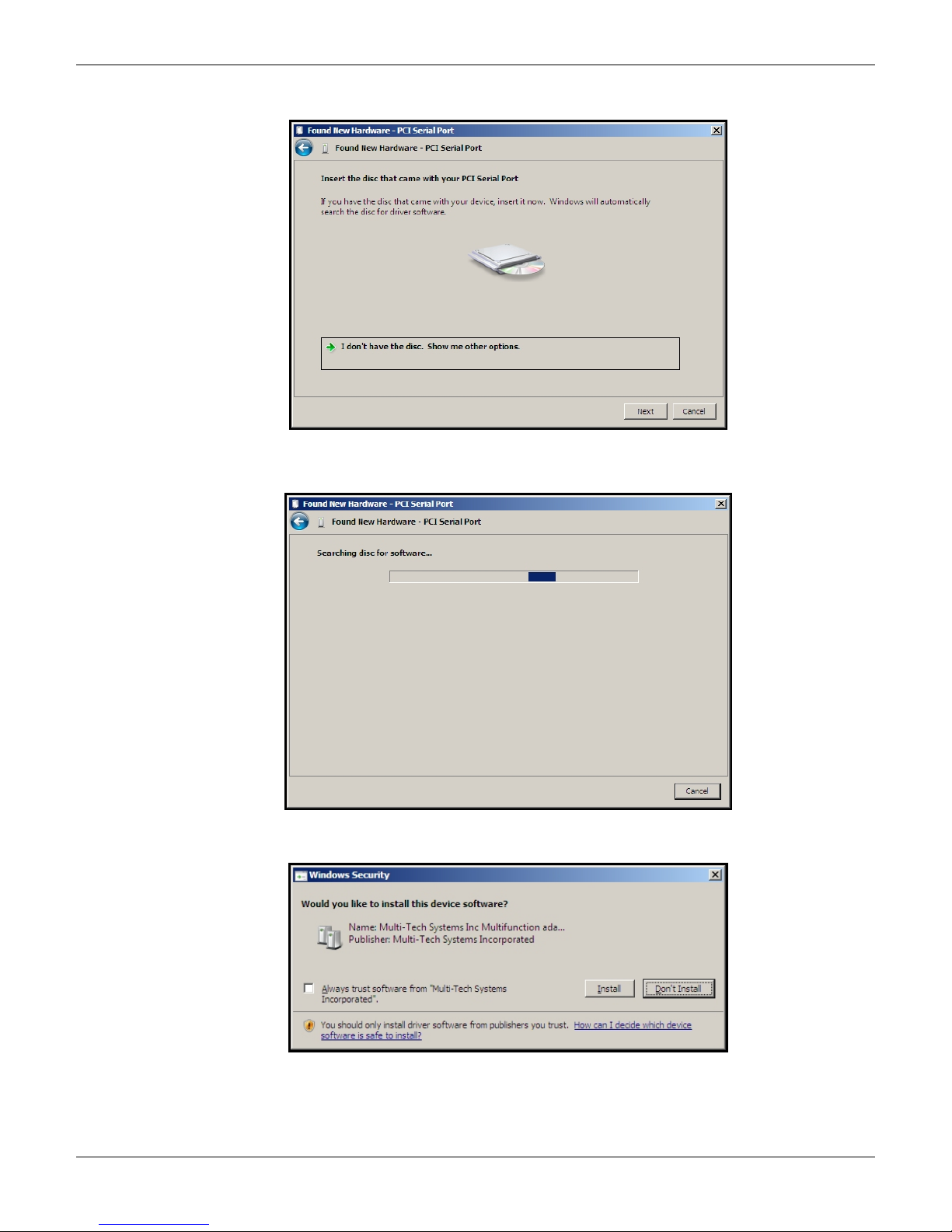
5. The next screen prompts you to Insert the disc that came with your PCI Serial Port. If you have the
disc that came with your card, insert it now.
Click Next.
6. Searching disc for software…screen appears.
7. Windows can’t verify the publisher of this driver software screen appears.
Click Install.
11
Page 12
Chapter 3 – Software Installation
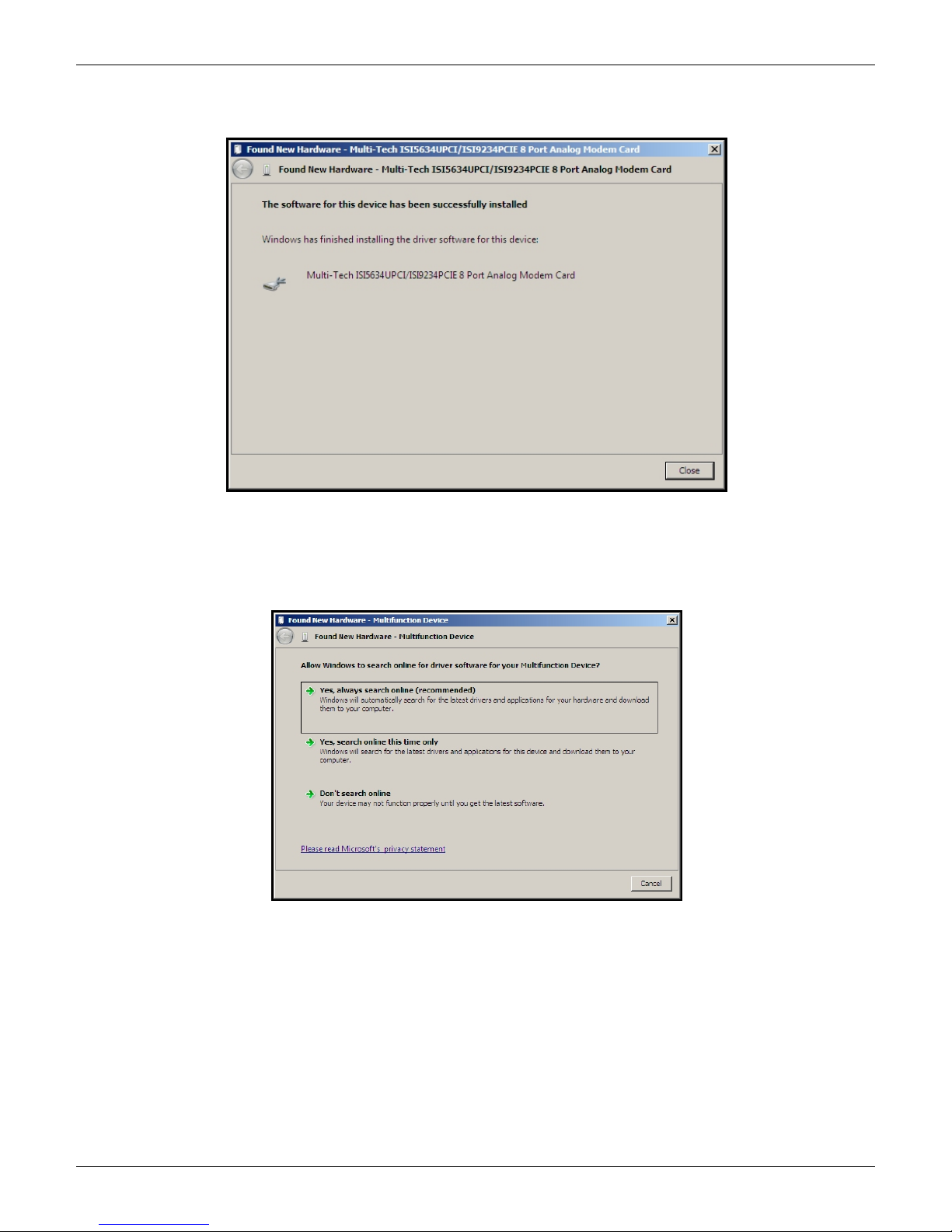
8. When the software for this device has been successfully installed screen appears, Windows has
finished installing the driver software for this device: Multi-Tech ISI5634UPCI/ISI9234PCIE 8 Port
Analog Modem Card.
Click Close.
Installation of the Communications Port
9. A Found New Hardware – Multifunction Device screen appe ars and asks: Allow Windows to
search online for driver software for your Multifunction Device?
Select Don’t search online.
12
Page 13
Chapter 3 – Software Installation
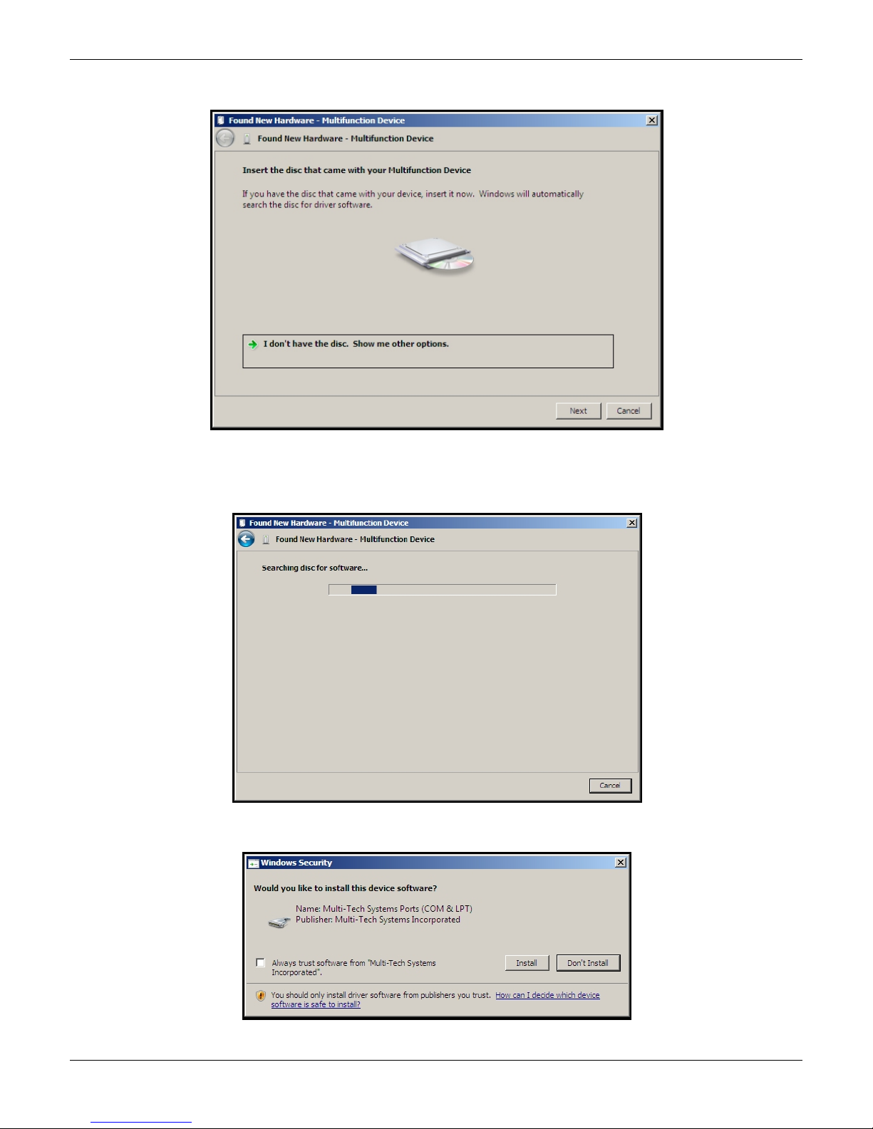
10. The Found New Hardware – Multifunction Device screen appears. If you have the disc that came with
your device, insert it now.
The ISI Card CD is still in the CDROM drive. Click Next.
11. Searching disc for software…screen appears.
12. Windows can’t verify the publisher of this driver software screen appears.
Click Install.
13
Page 14
Chapter 3 – Software Installation
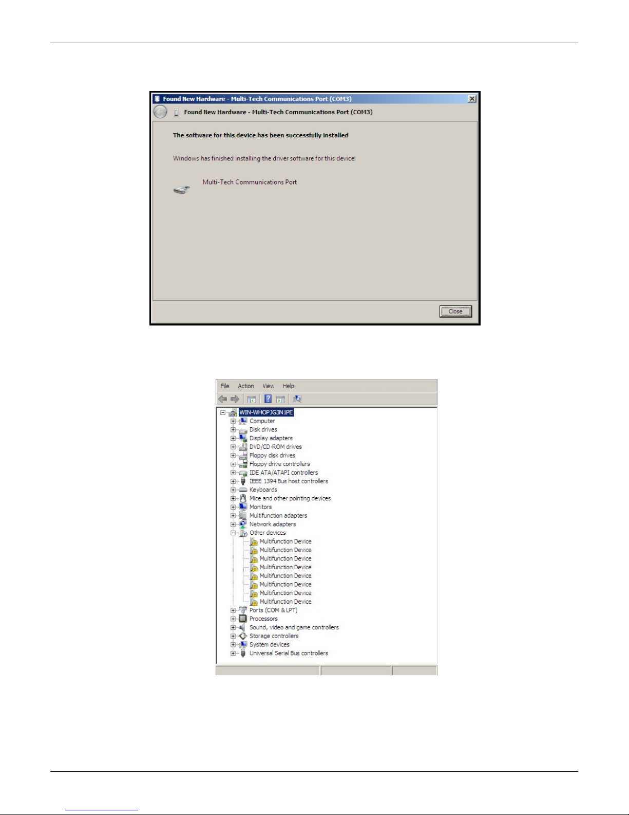
13. The Found New Hardware – Multi-Tech Communications Port (COM3) screen appears. The
software for this device has been successfully installed. Windows has finished installing the driver
software for this device: Multi-Tech Communications Port.
Click Close.
14. If you open Device Manager, you will see Other devices with four Multifunction Devices for the ISI-4
Card. Similarly, for the ISI-8 Card you will see eight Multifunction Devices.
14
Page 15

Installation of the Modem
15. A Found New Hardware – Multifunction Device screen appears and asks: Allow Windows to
search online for driver software for your MultiTech Systems MT9234SMI?
Select Don’t search online.
16. The Found New Hardware – MultiTech Systems MT9234SMI-V92 screen appears. If you have the
disc that came with your device, insert it now.
Chapter 3 – Software Installation
The ISI Card CD is still in the CDROM drive. Click Next.
15
Page 16

Chapter 3 – Software Installation
17. Searching disc for software screen appears.
18. Windows can’t verify the publisher of this driver software screen appears.
19. Select Install this driver software anyway
20. The software for this device has been successfully installed screen appears. Windows has finished
installing the driver software for this device: MultTech Systems MT9234SMI.
21. Click Close.
16
Page 17

Chapter 3 – Software Installation
22. View the Device Manager as the Modems are being installed. For the ISI1-4, the installa tion wiz ard
must install four Multifunction Devices. Similarly, for the ISI1-8, the installation wizard must install eight
Multifunction Devices under Other Devices.
When Multi-Tech Systems MT9234SMI-v92 #8 is displayed, the eight modems on the ISI Card are
successfully installed.
23. When all modems have been installed, you need to reboot.
Completion.
Software installation for the ISI Card is complete. You may need to configure the modem for your country/region,
refer to Configure your modems for Country/region at the end of this chapter.
Verification.
You can verify successful installation of the ISI Card, the ports, and the modems by going to Start I Control
Panel I System. Select the Hardware tab and click on Device Manager to view a list of devices. Then click on
"Multi-port serial adapters" to view the entry for the card driver. Click on "Ports (COM & LPT)" to view the list of
ports established. Click on "Modems" to view the list of modems installed to the ports.
Subsequent Installations.
After any ISI Card has been installed in a computer, the sequence for installing any additional boards will be
different. Some screens in the installation wi zard will be omitted, making the process somewhat shorter. Because
the installation affects the computer's registry, even if an ISI Card has been uninstalled after its initial installation,
any subsequent installation will be shortened in this way.
Un-Installing ISI Drivers
Conduct the un-installation in this order: remove the modems associated with the ISI Card first, then the
ports, and, finally, the ISI dri v e r. F o ll o w in g t hi s p ro c ed u r e w i l l e n su r e r e m ov a l of all ISI components. We present
details below.
17
Page 18

Chapter 3 – Software Installation
Delete Modem Drivers.
1. Go to Control Panel I System. Go to the Hardware tab and click on Device Manager. The Device
Manager list will appear.
2. Click on Modems to expand the list.
3. Select one of the modem drivers being used with the ISI Card. The modem drivers are designated
"MultiTech systems MT5634SMI-V92" (followed by number designations for all modems except the
first, #2, #3, etc.). Right-click on the first modem driver to be deleted (the order of removal is not
important) and select "Uninstall."
18
Page 19

Chapter 3 – Software Installation
4. At the Confirm Device Removal screen, click OK.
5. Repeat steps 4 and 5 for each additional modem driver to be removed.
Delete COM Ports.
1. Go to Control Panel I System. Go to the Hardware tab and click on Device Manager. The Device
Manager list will appear.
2. Click on Ports (COM & LPT) to expand the list.
3. Select one of the COM ports being used with the ISI Card. These are designated as "MultiTech
Communications Port (COMx)" where x is usually 3 or greater.
19
Page 20

Chapter 3 – Software Installation
4. Right-click on the first port to be deleted (the order of removal is not important) and select "Uninstall."
5. At the Confirm Device Removal screen, click OK.
6. Repeat steps 4 and 5 for each additional ISI COM port to be removed.
20
Page 21

Delete ISI Card Driver.
1. Go to Control Panel I System. Go to the Hardware tab and click on Device Manager. The Device
Manager list will appear.
2. Click on Multi-port serial adapters to expand the list.
3. Select the entry for the specific ISI Card to be removed, either "MultiTech
ISI5634UPCI/ISI9234PCIE-X Port Analog Modem Card" . Here "x" will be either 4 or 8. If multiple ISI
Cards are present, those beyond the first will be further specified as #2, #3, etc.
4. Right-click on the first ISI Card to be deleted (the order of removal is not important) and select
"Uninstall."
Chapter 3 – Software Installation
5. At the Confirm Device Removal screen, click OK.
6. Repeat steps 4 and 5 for each additional ISI Card to be removed.
7. Shut down the computer.
8. With the computer's power off, you can remove the ISI Card physically from the computer.
21
Page 22

Chapter 3 – Software Installation
Driver Installation for Windows XP/2003/2000
The following driver installation procedure is based Windows XP 32-bit Operating System. The procedure may vary
slightly for the Windows 2003 and 2000 Operating Systems.
A series of 'installation wizard' screens will appear repeatedly during this proc edure. This is not an error. Do
not discontinue the procedure when the 'installation wizard' screens repeatedly appear.
Card Driver Installation.
1. Power up your computer.
2. In some situations the operating system will display a Found New Hardware Wizard screen and asks
you: Can Windows connect to Windows Update to search for software? Select No, not this time.
Then click Next.
3. Windows XP will detect the ISI Card. A small Found New Hardware screen emerges from the 'tray'
area (at bottom right of screen) and appears briefly. Then a larger Found New Hardware Wizard
screen. Select Install from a list or specific location (Advanced) and Click Next.
22
Page 23

Chapter 3 – Software Installation
4. Please choose your search and installation options screen appears.
Select Include this location in the search: and Click Browse. Browse to the Drivers folder on
your ISI product CD, then select the Drivers folder and then the Win2k-XP-2003 folder, then the
Win32bit-2k-XP-2003 folder. If you are installing drivers on an XP 64-bit Operating System, you
would browse to the Win64bit-2k-XP-2003 folder. Click Next.
5. A transient screen appears while the wizard searches…
6. Then a Hardware Installation—Windows Logo Testing screen will appear. Verify that the software being
loaded is for the ISI Card. (I f th e d evi ce d es crip tio n o n th is screen matches the ISI Card you are installing,
then you can be sure that the correct software is being loade d. If no t, you sh o u ld c lic k Stop
Installation and re-do this driver installation procedure using the correct path for the driver files, typically
CD-ROM drive:\drivers\Win2k-XP-2003\.) When asked whether or not to continue the installation
(presuming that the device descripti on matches the ISI Card), you should click "Continue Anyway."
23
Page 24

Chapter 3 – Software Installation
7. Please wait while the wizard installs the software.. screen appears.
8. A completing the Found New Hardware Wizard screen appears. Click Finish.
Port and Modem Installation
Immediately after the ISI Card driver installation has been completed, another set of installation wizard screens will
appear. With th i s i n st a l l at i on w iz a r d, y o u will in stall ISI port s and modem drivers into the computer's operating
system and then associate the modem driver with the ports.
This installation sequence occurs very rapidly and is repetitive. The installation wizard may appear to be
"stuck" in an endless loop, but that is not the case. For the ISI1-4, the in stallation wizard must install four ports and
four modem drivers, and must make four modem/port associations. Similarly, for the ISI1-8, the installation wizard
must install eight ports and eight modem drivers, and must make eight modem/port associations.
Each port and each modem driver entails a separate wizard screen sequence.
24
Page 25

Chapter 3 – Software Installation
Port Installation.
This is the beginning of a sequence of screens that will be repeated for each port to be installed.
Respond to the wizard screens as follows:
1. If the Welcome to the Found New Hardware Wizard screen – Can Windows connect to Windows
update to search for software? appeared when you were installing the driver, it will come up here also.
Select No, not this time. Then click Next.
2. The Found New Hardware Wizard screen appears with Multifunction Device. Select Install from a
list or specific location (Advanced).
Then click Next.
25
Page 26

Chapter 3 – Software Installation
3. Please choose your search and installation options screen appears.
Select Include this location in the search:. Click Browse. This may already be populated with
the correct path from the first wizard; in that case simply click Next and skip step 5.
4. Browse to the Drivers folder on your ISI product CD, then select the Drivers folder and then the
Win2k-XP-2003 folder, then the Win32bit-2k-XP-2003 folder. If you are installing drivers on an XP
64-bit Operating System, you would browse to the Win64bit-2k-XP-2003 folder. Click Next.
5. A second Hardware Installation - Windows Logo Testing screen appears.
Click Continue Anyway.
6. Please wait while the wizard installs the software screen appears.
26
Page 27

Chapter 3 – Software Installation
7. For each port, a completion screen will appear. Click Finish.
This wizard screen sequence will be repeated for each port, four times for the ISI923 4P CIE -4 an d ei ght t im es
for t h e ISI9234PCIE-8.
Modem Driver Installation.
Next, a small message dialog window will emerge briefly from the 'Tray' area at the bottom right of the screen
(New Hardware Found) followed immediately by the Found New Hardware Wizard screen. This is the
beginning of a sequence of screens that will be repeated for each modem to be installed.
Respond to the wizard screens as follows:
1. If the Welcome to the Found New Hardware Wizard screen – Can Windows connect to Windows update
to search for software? appeared when you were installing the driver, it will come up here also.
Select No, not this time. Then click Next.
27
Page 28

Chapter 3 – Software Installation
2. The Found New Hardware Wizard screen appears with Multi-Tech Systems MT9234SMI. Click on Install from
a list or specific location (Advanced).
Then click Next.
3. At each Found New Hardware Wizard —Please choose your search screen, select "Include this
location ..." and browse to CDROM-drive:\drivers\Win2k-XP-2003.
Then click Next.
4. Transient screens will appear until XP locates the driver files.
5. At each Hardware Installation—Windows Logo Testing screen, click "Continue Anyway."
28
Page 29

6. Transient screens will appear while files are being copied.
7. For each port, a completion screen will appear. Click Finish.
Chapter 3 – Software Installation
This wizard screen sequence will be repeated for each modem, four times for the ISI-4 a nd ei ght t imes for
the ISI-8.
8. When all modems have been installed, you need to reboot.
Completion.
Software installation for the ISI Card is complete. You may need to configure the modem for your country/region,
refer to Configure your modems for Country/region at the end of this chapter.
Verification.
You can verify successful installation of the ISI Card, the ports, and the modems by going to Start I Control
Panel I System. Select the Hardware tab and click on Device Manager to view a list of devices. Then click on
"Multi-port serial adapters" to view the entry for the card driver. Click on "Ports (COM & LPT)" to view the list of
ports established. Click on "Modems" to view the list of modems installed to the ports.
Subsequent Installations.
After any ISI Card has been installed in a computer, the sequence for installing any additional boards will be
different. Some screens in the installation wi zard will be omitted, making the process somewhat shorter. Because
the installation affects the computer's registry, even if an ISI Card has been uninstalled after its initial installation,
any subsequent installation will be shortened in this way.
29
Page 30

Chapter 3 – Software Installation
Un-Installing ISI Drivers
Conduct the un-installation in this order: remove the modems associated with the ISI Card first, then the
ports, and, finally, the ISI dri v e r. F o ll o w in g t hi s p ro c ed u r e w i l l e n su r e r e m ov a l of all ISI components. We present
details below.
Delete Modem Drivers.
1. Go to Control Panel I System. Go to the Hardware tab and click on Device Manager. The Device
Manager list will appear.
2. Click on Modems to expand the list.
30
Page 31

Chapter 3 – Software Installation
3. Select one of the modem drivers being used with the ISI Card. The modem drivers are designated
"MultiTech systems MT9234SMI" (followed by number designations for all modems except the first, #2,
#3, etc.). Right-click on the first modem driver to be deleted (the order of removal is not important) and
select "Uninstall."
4. At the Confirm Device Removal screen, click OK.
5. Repeat steps 3 and 4 for each additional modem driver to be removed.
31
Page 32

Chapter 3 – Software Installation
Delete COM Ports.
1. Go to Control Panel I System. Go to the Hardware tab and click on Device Manager. The Device
Manager list will appear.
2. Click on Ports (COM & LPT) to expand the list.
3. Select one of the COM ports being used with the ISI Card. These are designated as "MultiTech
Communications Port (COMx)" where x is usually 3 or greater.
4. Right-click on the first port to be deleted (the order of removal is not important) and select "Uninstall."
32
Page 33

Chapter 3 – Software Installation
5. At the Confirm Device Removal screen, click OK.
6. Repeat steps 4 and 5 for each additional ISI COM port to be removed.
Delete ISI Card Driver.
2. Go to Control Panel I System. Go to the Hardware tab and click on Device Manager. The Device
Manager list will appear.
2. Click on Multi-port serial adapters to expand the list.
3. Select the entry for the specific ISI Card to be removed, either "MultiTech ISI5634UPCI/ISI9234PCIE-
X Port Analog Modem Card" . Here "x" will be either 4 or 8. If multiple ISI Cards are present, those beyond
the first will be further specified as #2, #3, etc.
4. Right-click on the first ISI Card to be deleted (the order of removal is not important) and select "Uninstall."
33
Page 34

Chapter 3 – Software Installation
5. At the Confirm Device Removal screen, click OK.
6. Repeat steps 4 and 5 for each additional ISI Card to be removed.
7. Shut down the computer.
8. With the computer's power off, you can remove the ISI Card physically from the computer.
34
Page 35

Chapter 3 – Software Installation
Installing the ISI Driver in Linux
MultiTech' s version 1 . 01 dr i v er f or th e ISI Card s wor k s wit h the 2.4.x Linux kernel. It has been tested with
RedHat Release Versions 7.3, 8.0, and 9.0.
System Requirements, Prerequisites, & Conditions of Use
Hardware Platform: Intel x86
Linux kernel version: 2.4.x
GNUC Compilerversion: 2.72 or later
ISI capacity per computer: up to 4 boards
Drivertype: use MultiTech driver only; do not use any drivers included with the Linux OS (like
Exar drivers).
Full Linux Installation: For the ISI Card to operate properly, all component s of the Li n ux OS s ho ul d b e
installed. If the ISI Card does not operate properly in a Linux installation
where some components are missing, then those missing Linux components
should be added and the ISI Card should be uninstalled and re-installed.
(The 'make' utility, the GNU C compiler, and the kernel sources need to be
installed on your system. If any of these are missing, the compilation will fail.
Most later Linux OSs install these elements automatically. In any event, f or
best results, the Linux OS installation should include all elements.)
Linux Driver Installation Overview
The Linux driver files can be obtained from the Multi-Tech FTP site, or from the ISI Product CD. Installation
consists of three processes:
(A) building the driver using the 'make install' script,
(B) creating tty device names, and
(C) verifying successful loading of the driver.
We describe this installation in detail in the sections below.
Note: All Linux line command expressions are case-sensitive. The commands shown in this procedure
will work only I fyou use capital letters and
lower-case letters exactly as shown.
Building the Linux Driver
1 . Create a temporary directory : "mkdir /mtsi_upci"
2. C o py t h e t a r f i l e t o the t e m p ora r y d irect ory "cp ISI_U_PCI_LINUX_V_1 01 .tar.gz
/mtsi_upci"
3. Go to the temporary directory "cd /mtsi_upci"
4. Untar the file, "ta rxvf zISI _U_P CI_LI NU X_V_ 1 01 . tar. gz" . Th i s command will unzip the source files to the
"mtsi_upci_driver" directory.
5. Switch to the newly created directory "cd mtsi_upci_driver"
6. Run the "make" command. The files "mtsi_upci.o" and "resetport" will be created.
7. Run the "make install" script. The script will create the driver module and tty devices, and modify the rc files
in order to load the driver automatically on system reboot. Successful compilation and loading of the module is
displayed on the screen. Specifically, when the script has finished running successfully, it will disp lay the
message "MultiTech ISI driver loaded successfully YY" The script will also create the "ttyMUxy" ports and
list the ports it has created. If this message and a list of ports do not appear, watch for error messages.
35
Page 36

Chapter 3 – Software Installation
Creating Linux TTY Device Names
1. This driver retains the standard serial device properties: dial-in port files (named in the form "ttyM U xy"), and
call-out port files (named in the form "cumxy"). File names of these two special types become associate d
with each serial port . The first file type is for the dial-in port and has a name of the form "ttyMUxy" where
the "x" denotes the card number and the final "y" denotes the port number on that card. The second file
type is for the call-out po rt and has a name of the form "cumxy" where, again, the "x" denotes the card
number and the "y" denotes the port number on that card.
2. Consider the situation of installing two 8-port Modem Cards in the server computer. In that case, the driver
wou ld create TTY device s "ttyMUla" to "ttyMUlh" and devices "cumla" to "cumlh" under the "/dev"
dire c t o r y for car d 1 . S imilar l y, devices tt y M U 2 a to ttyMU2h and devices "cum2a" to "cum2h" would be
created for card 2. (If a 4-port card were installed as card 1, the driver would create TTY devices "ttyMUla" to
"ttyMUld.")
Verifying Successful Loading of the Linux Driver
1. To confirm the successful loading of the driver, execute the command "lsmod". The driver "mtsi_upci"
should be listed in the list of mod ules. If t h e d r iver i s n o t lis t e d , i n v o k e t h e " l smod " command again and
watch for errors.
2. Check that the tty devices (with names of the form "ttyMUxy") are listed under the /dev directory. If the tty
devices are not listed, invoke the ". /mknod_script" command again (it was previously run as part of the
"make install" script in step 7 of the "Bu i lding the Linux Driver" procedure) and watch for errors.
3. To confirm that the tty devices function for each modem on the ISI Card, execute the utility "minicom" and
dial out on each modem.
Un-Installing the Linux ISI Driver
1. Run the "make clean" script. You must run this command from the "mtsi_upci_driver" directory.
2. The "make clean" script will delete the "resetport" and "mtsi_upci.o" files.
3. Run the "make uninstall" script.
4. You must run this command from the "mtsi_upci_driver" directory. The "make clean" script will remove the
module "mtsi_upci".
5. Execute the "lsmod" command. The "mtsi_upci" module should no longer be listed. If this module is still
listed, then invoke the co mmand "rmmod mtsi_upci" and check again to see whether or not the module
is listed.
6. Delete serial ports (these are files with names of the fo rm "ttyMUxy").
7. To do so, go to the "dev" directory.
8. Enter the command "rm ttyMUZ".
Using the Linux Port Reset Utility
For the Modem Cards, the port -reset utility all ows you t o reset ports without rebooting. For the modem cards, the
port-reset utility allows you to reset both ports and mod ems without rebooting.
To r ese t a s erial por t, the DTR pin is set t o the l ow l ogic l evel f or o ne second. To reset the modem port, the
Reset pin is toggled (i.e., its logic state is inverted and then restored).
1. To reset the port (for serial card) or modem (for modem card) run the command "resetport /dev/ttyMUxy"
(where 'x' stands for card number and 'y' for the port number).
2. On the Modem Cards, the DTRLED will toggle indicating that the reset has occurred and this toggling might be
observable on the modem attached to the port (if the modem is equipped for this indication). There is no
similar indication of successful reset on the modem cards.
36
Page 37

Chapter 3 – Software Installation
Configuring your Modems for your Country
Different countries have different requirements for how modems must function. Therefore, before you use the
modems in your ISI Card, you must configure them to match the defaults of the country in which you are using
them. Use the Global Wizard to configure each modem as described below. The Global Wizard configuration utility
works with computers running Windows 2000/2003/XP/Vista/2008.
1. Insert the ISI product CD into the CD-ROM drive. The main splash screen appears.
2. Click Initial Setup & Country Sel.
3. The Global Wizard page appears. You can select to run the Global Wizard from the CD or install it on your
hard drive. Click on the Install or Run button.
4. The Global Wizard dialog box appears. Click Next.
5. The Global Wizard searches for your modems and identifies them. Click Next. Select a modem to
configure. Click Next.
6. Select the country in which the modem will be used, and then click Next.
7. Review your choice of country. If it is correct, click Next to configure the modem.
8. When Global Wizard announces that the parameters have been set, click Finish to exit.
9. Repeat steps 4 through 8 for each modem on the ISI Card.
37
Page 38

Chapter 4 – Reset Utility
Chapter 4 – Reset Utility
The Reset Utility allows you to reset a single modem or reset all the modems.
PREREQUISITE: The ISI drivers must be install before the Reset Utility can function.
1. Insert the ISI Product CD into the CD-ROM drive. The CD starts automatically. Any other utility accessing
the first com port needs to be closed before you can access the first com port in the Reset Utility.
2. When the main screen appears, click on Install Reset Utility icon. The ISI Port Modem Reset screen
appears with the Select first COM port on the ISI Card drop down window blank.
3. Click OK and the Select first COM port on the ISI Card displays the COM ports, e.g., COM3. If you want to
display all the COM ports, click on Display All Ports and all the ports are displayed in the drop down
window.
4. Click on the drop down arrow and choose the first COM port for your ISI Card.
5. Then select the modem to be reset by clicking on the corresponding Modem button. The following
message will be displayed if the modem is successfully reset.
The following error message is displayed if you select other than the first COM port.
38
Page 39

Chapter 5 – Warranty, Service, & Tech Support
Chapter 5 - Warranty, Service, & Tech Support
Multi-Tech Warranty Statement
Multi-Tech Systems, Inc., (hereafter “MTS”) warrants that its products will be free from defects in material or
workmanship for a period of two, five, or ten years (depending on model) from date of purchase, or if proof of
purchase is not provided, two, five, or ten years (depending on model) from date of shipment.
MTS MAKES NO OTHER WARRANTY, EXPRESS OR IMPLIED, AND ALL IMPLIED WARRANTIES OF
MERCHANTABILITY AND FITNESS FOR A PARTICULAR PURPOSE ARE HEREBY DISCLAIMED.
This warranty does not apply to any products which have been damaged by lightning storms, water, or power
surges or which have been neglected, altered, abused, used for a purpose other than the one for which they were
manufactured, repaired by Customer or any party without MTS’s written authorization, or used in any manner
inconsistent with MTS’s instruction s.
MTS’s entire obligation under this warranty shall be limited (at MTS’s option) to repair or replacement of any
products which prove to be defective within the warranty period or, at MTS’s option, issuance of a refund of the
purchase price. Defective products must be returned by Customer to MTS’s factory — transportation prepaid.
MTS WILL NOT BE LIABLE FOR CONSEQUENTIAL DAMAGES, AND UNDER NO CIRCUMSTANCES WILL ITS
LIABILITY EXCEED THE PRICE FOR DEFECTIVE PRODUCTS.
Repair Procedures for U.S. and Canadian Customers
In the event that service is required, products may be shipped, freight prepaid, to our Mounds View, Minnesota
factory:
Multi-Tech Systems, Inc.
2205 Woodale Drive
Mounds View, MN 55112
Attn: Repairs, Serial # ____________
A Returned Materials Authorization (RMA) is not required. Return shipping charges (surface) will be paid by MTS to
destinations in U.S. and Canada.
Please include, inside the shipping box, a description of the problem, a return shipping addre ss (must have street
address, not P.O. Box), and your telephone number. If the product is out of warranty, a payment in advance is
required. Acceptable means of payment include credit card, wire transfer or a check in U.S. dollars drawn on a U.S.
Bank.
For out of warranty repair charges, go to COMPANY/Policies/warranty/
Extended two-year overnight replacement service agreements are available for selected products. Please call MTS
at (888) 288-5470, extension 5308 or visit our web site at PARTNERS/Programs/overnight_replacement
on rates and coverages.
Please direct your questions regarding technical matters, product configuration, verification that the product is
defective, etc., to our Technical Support department at (800) 972-2439 or email support@multitech.com
direct your questions regarding repair expediting, receiving, shipping, billing, etc., to our Repair Accounting
department at (800) 328-9717 or (763) 717-5631, or email mtsrepair@multitech.com
Repairs for damages caused by lightning storms, water, power surges, incorrect installation, p hysical abuse, or
user-caused damages are billed on a time-plus-materials basis.
for details
. Please
.
Repair Procedures for International Customers (Outside U.S.A. and Canada)
Your original point of purchase Reseller may offer the quickest and most economical repair option for your MultiTech product. You may also contact any Multi-Tech sales office for information about the nearest distributor or
other repair service for your Multi-Tech product. The Multi-Tech sales office directory is available at
http://www.multitech.com/ PARTNERS/Channels/offices/
In the event that factory service is required, products may be shipped, freight prepaid to our Mounds View,
Minnesota factory. Recommended international shipment methods are via Federal Express, UPS or DHL courie r
services, or by airmail parcel post; shipments made by any other method will be refused. Please include, inside the
39
Page 40

Chapter 5 – Warranty, Service, & Tech Support
shipping box, a description of the problem, a return shipping address (must have street address, not P.O. Box),
your telephone number, and if the product is out of warranty, a payment in advance is required. Acceptable means
of payment include credit card, wire transfer or a check in U.S. dollars drawn on a U.S. bank. Repaired units shall
be shipped freight collect, unless other arrangements are made in advance.
Please direct your questions regarding technical matters, product configuration, verification that the product is
defective, etc., to our Technical Support department nearest you or email support@multitech.com
U.S., please direct your questions regarding repair expediting, receiving, shipping, billing, etc., to our Repair
Accounting department at +(763) 717-5631 in the U.S.A., or email mtsrepair@multitech.com
Repairs for damages caused by lightning storms, water, power surges, incorrect installation, p hysical abuse, or
user-caused damages are billed on a time-plus-materials basis.
. When calling the
.
Repair Procedures for International Distributors
International distributors should contact their MTS International sales representative for information about the repair
of the Multi-Tech product(s).
Please direct your questions regarding technical matters, product configuration, verification that the product is
defective, etc., to our International Technical Support department at +(763)717-5863. When calling the U.S., please
direct your questions regarding repair expediting, receiving, shipping, billing, etc., to our Repair Accounting
department at +(763) 717-5631 in the U.S.A. or email mtsrepair@multitech.com
.
Repairs for damages caused by lightning storms, water, power surges, incorrect installation, p hysical abuse, or
user-caused damages are billed on a time-plus-materials basis.
Replacement Parts
SupplyNet, Inc., can supply you with replacement power supplies, cables and connectors for selected Multi-Tech
products. You can place an order with SupplyNet via mail, phone, fax or the Internet at the following addresses:
Mail: SupplyNet, Inc.
614 Corporate Way
Valley Cottage, NY 10989
Phone: 800 826-0279
Fax: 914 267-2420
Email: info@thesupplynet.com
Internet: http://www.thesupplynet.com
40
Page 41

Chapter 5 – Warranty, Service, & Tech Support
Software User License Agreement
The ISI drivers and firmware are licensed by Multi-Tech Systems, Inc. to the original end-user purchaser of the
product, hereafter referred to as Licensee. The License includes the distribution diskette or CD-ROM, other
accompanying programs, and the documentation.
The ISI drivers and firmware, hereafter referred to as Software, consists of the computer program files included on
the original distribution diskette.
Licensee agrees that by purchase and/or use of the Software, he hereby accepts and agrees to the terms of
this License Agreement.
In consideration of mutua l covenants contained herein, and other good and valuable considerations, the receipt
and sufficiency of which is acknowledged, Mu lti-Tech Systems, In c. does hereby gran t to the Licensee a nontransferrable and nonexclusive license to use the Software and accompanying documentation on the following
conditions and terms:
The software is furnished to the Licensee for execution and use on a single computer system only and may be
copied (with the inclusion of the Multi-Tech Systems, Inc. copyright notice) only for use on that computer system.
The Licensee hereby agrees not to provide or otherwise make available any portion of this software in any form to
any third party without the prior express written approval of Multi-Tech Systems, Inc.
Licensee is hereby info rmed that this Softwa re cont a ins con fidential , proprietary, and valuable trade secrets
developed by or licensed to Multi-Tech Systems, Inc. and agrees that sole ownership shall remain with MultiTech Systems, Inc.
The Softwa re is copyrighted. Except as prov ided h erein, the Software and documentation supplied under this
agreemen t may not be copied , reproduced, published, licensed, sublicensed, distributed, transferred, or made
available in any form, in whole or in part, to others, without expressed written permissio n of Multi-Tech Systems, Inc.
Copies of the Software may be made to replace worn or deteriorated copies for archive or backup procedures.
Licensee agrees to implement sufficient security measures to protect Multi-Tech Systems', Inc. proprietary
interests and not to allow the use, copying or transfer by any means, other than in accordance with this
agreement.
Licensee agrees that any breach of this agreement will be damaging to Multi-Tech Systems, Inc.
Licensee agrees that all warranties, implied or otherwise, with regard to this Software, including all warranties of
merchantability and fitness for any par tic ula r purp ose are exp res sly wa ive d, and no lia bil ity sh all ext end to any
damages, including consequential damages, whether known to Multi-Tech Syst ems, In c. It is here by expressly
agreed that Licensee's remedy is limited to replacement or refund of the license fee, at the option of Multi-Tech
Systems, Inc. for defective distribution media. There is no warranty for misused materials.
Neither this Software nor the accompanying documentation may be modified or translated without the written
per m i s s i on of M u l t i-Te c h Sy stems, Inc.
This agreement shall be governed by the laws of the State of Minnesota. The terms and conditions of this
agreement shall prevail regardless of the terms of any other submitted by the Licensee. This agreement
supersedes any proposal or prio r agreement. Lice nsee further agrees that th is License Agreement is the
complete and exclusive Statement of Agreement, and supersedes oral, written, or any other communications
between Multi-Tech Systems, Inc. and Licensee re lat ing to the subje ct m atter of thi s ag reeme nt i s not
assignable without written permission of an authorized agent of Multi-Tech Systems, Inc.
On-Line Warranty Registration
If you want to register your ISI Card on-line, you can do so at the following address:
http://www.multitech.com/register
41
Page 42

Appendices
Appendices
Appendix A— Cable Wiring Diagrams
The four modems on the ISI-4 are attached to phone receptacles by a single fan-out cable that has an RJ45
connector on one end (which connects to the card) and four RJ11 connectors on the other end (which connect to
phone receptacles). The eight modems ISI-8 are served by two s uch fan-out cables. The pino u t for the fan-out
cable is shown in Figure A-1.
Figure A-1 Pinout for ISI Fan-Out Cable
42
Page 43

Appendices
Appendix B—Regulatory Information
Note: This equipment has been tested and found to comply with the limits for a Class B digital device,
pursant to Part 15 of the FCC rules. These limits are designed to provide reasonable protection against
harmful in terf er enc e whe n th e equ ipm ent i s op erat ed in a re sid ent ial installation. This equipment generates,
uses, and can radiate radio frequency ene rgy , and if not ins talled and use d in accordancae with the
instruction manual, may cause harmful interference to radio communications. However, the re is no
guarantee that interference will not oc cur in a part icu lar in stall ati on. If t his equipment does cause
harmful interference to radio or television r eception, which can be determine d by turning the equipment
off and on, the user is encouraged to try to correct the intereference by one or more of the following
measures:
•
Reorient or relocate the receiving antenna.
•
Increase the separation between the equipment and receiver.
•
Connect the equipment into an outlet on a circuit differe nt from that of which the receiver is
connected.
•
Consult the dealer or an experienced radio/TV technician for help.
Warning: Changes or modifications to this unit, not expressly approved by the party responsible for
compliance, could void the user's authority to operate this equ ipmen t.
European Community Directives
The CE mark is affixed to the enclosed MultiTech product to confirm compliance with the following
European Community Directives:
Council Directive 89/336/EEC of 3 May 1989 on the approximation of the laws of Member States
relating to electromagnetic compatibility;
and
Council Directive 73/23/EEC of 19 February 1973 onthe harmonization of the laws of Member Stat es
relating to electrical equipment designed for use within certain voltage limits;
both amended by
Council Directive 93/68/EEC of22 July 199 3 on the harmonizat ion ofCE marking requirements.
43
Page 44

Appendices
Appendix C - Waste Electrical and Electronic Equipment (WEEE)
Statement
July, 2005
The WEEE directive places an obligation on EU-based manufacturers, distributors, retailers and importers
to take-back electronics products at the end of their useful life. A sister Directive, ROHS (Restriction of
Hazardous Substances) complements the WEEE Directive by banning the presence of specific
hazardous substances in the products at the design phase. The WEEE Directive covers all Multi-Tech
products imported into the EU as of August 13, 2005. EU-based manufacturers, distributors, retailers and
importers are obliged to finance the costs of recovery from municipal collection points, reuse, and
recycling of specified percentages per the WEEE requirements.
Instructions for Disposal of WEEE by Users in the European Union
The symbol shown below is on the product or on its packaging, which indicates that this product must not
be disposed of with other waste. Instead, it is the user’s responsibility to dispose of their waste equipment
by handing it over to a designated collection point for the recycling of waste electrical and electronic
equipment. The separate collection and recycling of your waste equipment at the time of disposal will help
to conserve natural resources and ensure that it is recycled in a manner that protects human health and
the environment. For more information about where you can drop off your waste equipment for recycling,
please contact your local city office, your household waste disposal service or where you purchased the
product.
44
Page 45

Appendix D – C-ROHS HT/TS Substance Concentration
依照中国标准的有毒有害物质信息
根据中华人民共和国信息产业部 (MII) 制定的电子信息产品 (EIP)
标准-中华人民共和国《电子信息产品污染控制管理办法》(第 39 号),也称作中国
RoHS,下表列出了 Multi-Tech Systems Inc. 产品中可能含有的有毒物质 (TS) 或有害物质 (HS)
的名称及含量水平方面的信息。
Appendices
成分名称
印刷电路板
电阻器
电容器
铁氧体磁环
继电器/光学部件
IC
二极管/晶体管
振荡器和晶振
调节器
电压传感器
变压器
扬声器
连接器
LED
螺丝、螺母以及
其它五金件
交流-直流电源
软件/文档 CD
手册和纸页
底盘
有害/有毒物质/元素
铅
(PB)
O O O O O O
X O O O O O
X O O O O O
O O O O O O
O O O O O O
O O O O O O
O O O O O O
X O O O O O
O O O O O O
O O O O O O
O O O O O O
O O O O O O
O O O O O O
O O O O O O
X O O O O O
O O O O O O
O O O O O O
O O O O O O
O O O O O O
X 表示所有使用类似材料的设备中有害/有毒物质的含量水平高于 SJ/Txxx-2006 限量要求。
O 表示不含该物质或者该物质的含量水平在上述限量要求之内
汞
(Hg)
镉
(CD)
六价铬
(CR6+)
多溴联苯
(PBB)
多溴二苯醚
(PBDE)
。
45
 Loading...