

Page 1

Intelligent Serial Interface
Server Cards
ISI5634UPCI & ISI9234PCIE
Quick Start Guide
Page 2

ISI Quick Start Guide
2
Quick Start Guide
P/N 82010753L, Revision D
Models ISI5634UPCI-4 & ISI5634UPCI-8
Models ISI9234PCIE-4 & ISI9234PCIE-8
This publication may not be reproduc ed, in whol e or in part, with out prior
expressed written permission from Multi-Tech Systems, Inc. All rights reserved.
Copyright © 2008 by Multi-Tech Systems, Inc.
Multi-Tech Systems, Inc. makes no representation or warranties with respect to the
contents hereof and specifically disclaims any implied warranties of merchantability or
fitness for any particular purpose. Furthermore, Multi-Tech Systems, Inc. reserves
the right to revise this publication and to make changes from time to time in the content
hereof without obligation of Multi-Tech Systems, Inc. to notify any person or
organization of such revisions or changes.
Record of Revision
Revision Date Description
A 01/15/04 Manual released.
B 10/24/07 Add PCI Express- bus archite cture.
C 04/14/08 Remove ISI Management Sof tware procedures.
D 06/06/08 Remove ISI460 4/8 Seria l Cards, and add pr ocedure s for
Windows Server 2008 Operating Sy stem support.
Trademarks
MultiModem, Multi-Tech, and the
Multi-Tech logo are trademarks of Multi-Tech
Systems, Inc.
Microsoft, Windows 2000, 2003, XP, Vista, 2008 are registered trademarks or
trademarks of Microsoft Corporation in the United States and/or other countries.
World Headquarters
Multi-Tech Systems, Inc.
2205 Woodale Drive
Mounds View, Minnesota 55112
Phone: 763-785-3500 or 800-328-9717
Fax: 763-785-9874
Technical Support
Country By Email By Phone
Europe, Middle E
ast, Africa: support@multitech.co.uk
+(44) 118 959 7774
U.S.,Canada, all others: support@multitech.com
(800) 972-2439 or
(763) 717-5863
Internet Address: http://www.multitech.com
Page 3
ISI Quick Start Guide
3
Safety Warnings
z This product must be installed by a qualified service person.
z When installing or servicing this product, the phone lines must be disconnected
to remove the risk of hazardous voltages.
z Never install telephone wiring during a lightning storm.
z Never install telephone jacks in wet locations unless the jack is specifically
designed for wet locations.
z This product is to be used with UL and CUL listed computers.
z Never touch uninsulated telephone wires or terminals unless the telephone line
has been disconnected at the network interface.
z Use caution when installing or modifying telephone lines.
z Avoid using a telephone (other than a cordless type) during an electrical storm.
There may be a remote risk of elect rical sh ock from lightning.
z Do not use the telephone to report a gas leak in the vicinity of the leak.
Hardware Installation Procedures
To install the ISI Card into your PCI-bus computer, follow the steps presented
below.
1. Turn off your computer and any peripheral equipment connected to it. The ISI
Card can be installed in a Pentium equivalent PCI bus computer.
2. Remove the cover of your computer as instructed in your computer's
documentation.
3. Before handling the ISI Card, discharge any static in your body by touching a
piece of grounded metal such as the computer chassis.
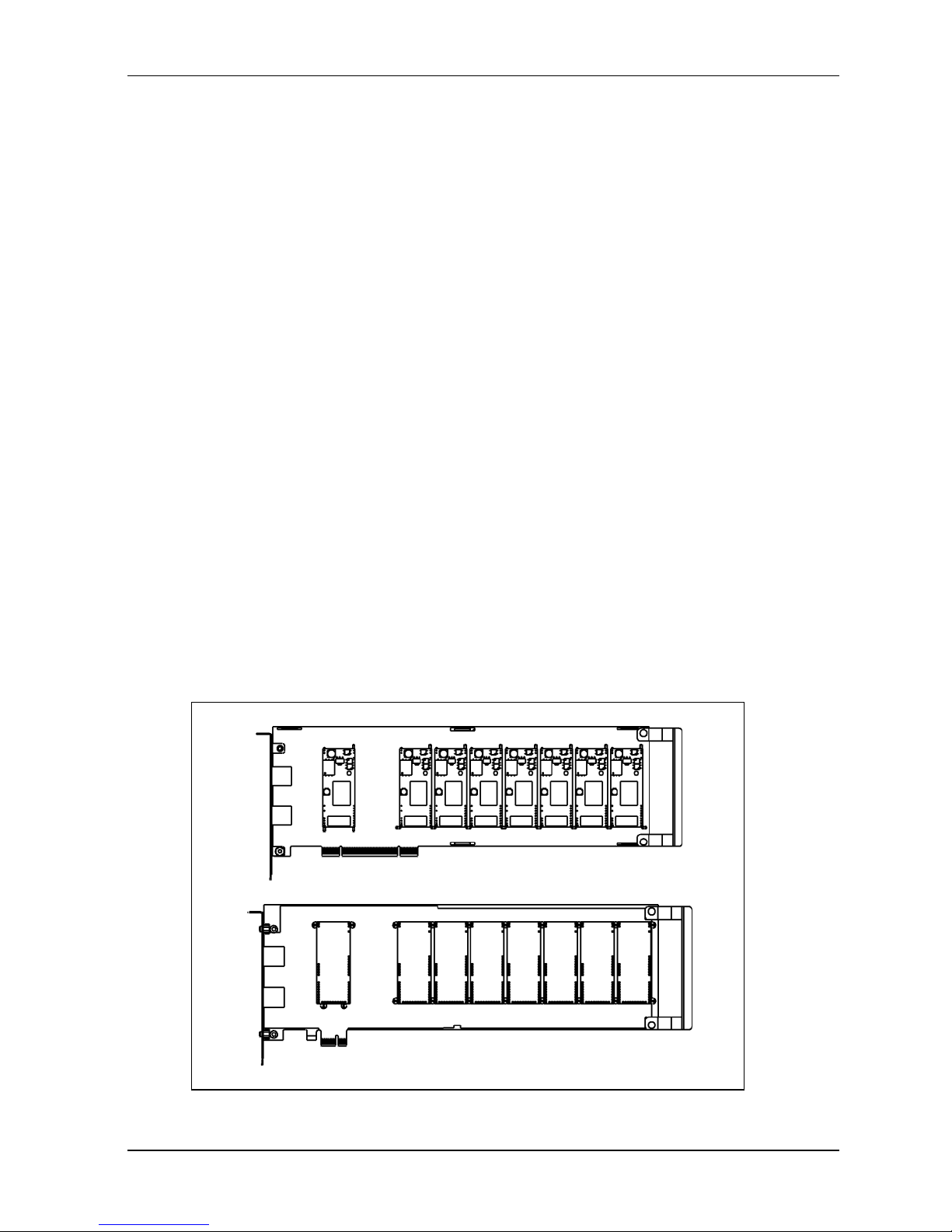
ISI5634UPCI-8
ISI9234PCIE-8
Page 4
ISI Quick Start Guide
4
4. Carefully remove the ISI Card from its antistatic bag, handling it only by the
mounting bracket and edges. Do not touch the gold-plated connectors a l on g t he
botto m ed g e . (You may want t o s av e packaging for possible future use.)
5. Locate the unused PCI slot you will be using for your ISI Card and remove the
slot cover according to in structions in your computer's documentatio n .
6. Install the ISI Card into the selected expansion slot in the same manner as any
other add-on card, as instructed in your computer’s documentation.
7. Fasten the retaining bracket to the computer chassis and replace cover on the
computer.
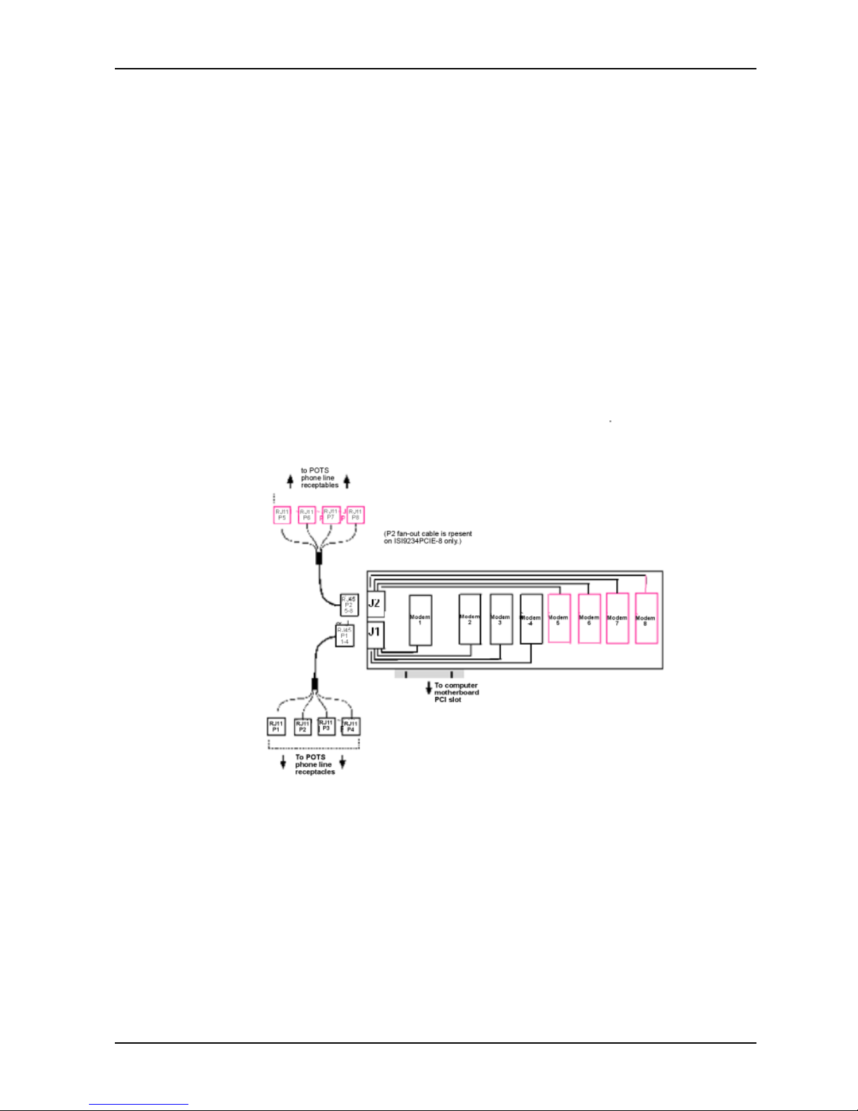
8. Cabling. The -4 card has one RJ-45 receptacle and one fan-out cable; the -8
card has two RJ- 45 receptacl es and two fan-out cables . Each f an-out ca ble
extends connections for four modems from the RJ-45 plug to four RJ-11 plugs.
Each RJ-11 plug should then be attached to a phone line receptacle. Attach the
RJ-45 connector into the appropriate RJ45 receptacle on the ISI Server card.
To view a pinout diagram of the Server Card Fan-Out Cables, se e Appendix A in
the user guide.
Fan-Out Cable for ISI Server Card
Page 5
ISI Quick Start Guide
5
Software Installation
Introduction
The I SI Car d sh ips wi th s oft ware/ dri vers f or e ach of the follo win g operating systems:
Windows
®
2008, Vista, XP, 2003 , 2000 S erver, a nd 2000 Advanced Server, and
Linux. You may need to configure the modems for your country/region, the procedure
for doing this is at the end of this Guide.
For additional Windows Operating System Software Installation Procedures, refer to
the User Guide.
Installing a device driver modifies your system . For this reason, only the super user
(system administrator) is allowed to perform the installation. If you cannot login as
administrator, find the person in your organization with this authorization (i.e.,
password). To begin driver installation, login as administrator.
Driver Installation for Windows Server 2008 and Vista
The following driver installation procedure is based on Windows Server 2008 64-bit
Operating System. The procedure may vary slightly for the Windows Server 2008 32bit Operating System
Card Driver Installation
1. Power up your computer.
2. Windows Server 2008 will detect the ISI Card. A screen from the tray area, at
the bottom right of the screen will appear briefly Installing Device Driver
Software.
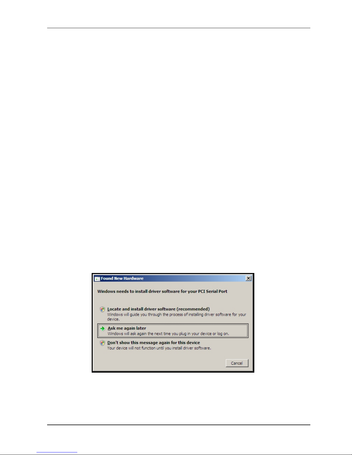
3. The Found New Hardware screen appears for Windows to install driver
software for your PCI Serial Port.
Click on Locate and install driver softwa re (recommended). Windows
will guide you through the process of installing driver software for your
device.
Page 6
ISI Quick Start Guide
6
4. A Found New Hardware – PCI Serial Port screen appears and asks: Allow
Windows to search online for driver software for your PCI Serial Port?
Select Don’t search online.
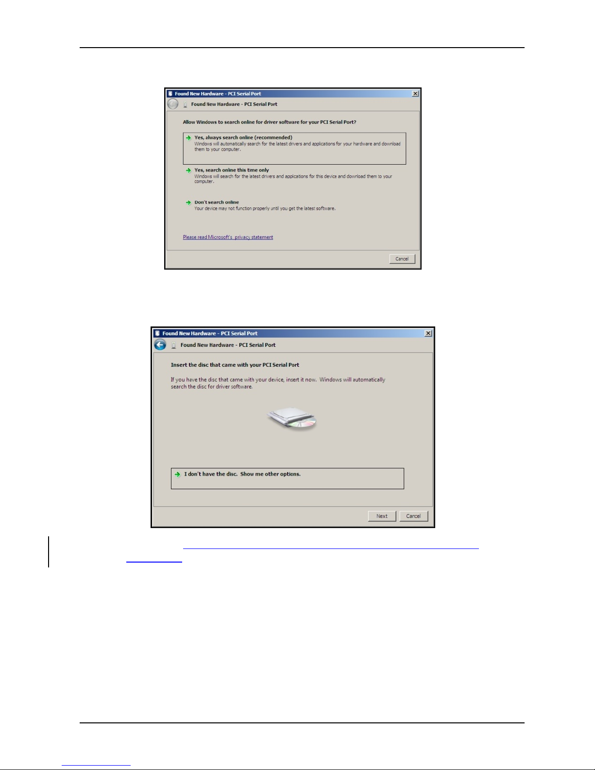
5. The next screen prompts you to Insert the disc that came with your PCI
Serial Port. If you have the disc that came with your card, insert it now.
Click Next. Windows may prompt you to search online, but this is not
necessary.
Page 7

ISI Quick Start Guide
7
6. Searching disc for software…screen appears.
7. Windows can’t verify the publisher of this driver software screen appears.
Click Install.
8. When the software for this device has been successfully installed screen
appears, Windows has finished installing the driver software for this device:
Multi-Tech ISI5634UPCI/ISI9234PCIE 8 Port Analog Modem Card.
Click Close.
Page 8

ISI Quick Start Guide
8
Installation of the Communications Port
9. A Found New Hardware – Multifunction Device screen appears and asks:
Allow Windows to search online for driver software for your Multifunction
Device?
Select Don’t search online.
10. The Found New Hardware – Multifunction Device screen appears. If you have
the disc that came with your device, insert it now.
The ISI Card CD is still in the CD ROM drive. Click Next.
Page 9

ISI Quick Start Guide
9
11. Searching disc for software…screen appears.
12. Windows can’t verify the publisher of this driver software screen appears.
Click Install.
13. The Found New Hardware – Multi-Tech Communications Port (COM3)
screen appears. The software for this device has been successfully installed.
Windows has finished installing the driver software for this defvice: Multi-
Tech Communications Port.
Click Close.
Page 10

ISI Quick Start Guide
10
14. If you open Device Manager, you will see Other devices with four
Multifunction Devices for the ISI-4 Card. Similarly, for the ISI-8 Card you will
see eight Multifunction Devices.
Installation of the Modem
15. A Found New Hardware – Multifunction Device screen appears and asks:
Allow Windows to search online for driver software for your MultiTech
Systems MT9234SMI?
Select Don’t search online.
Page 11

ISI Quick Start Guide
11
16. The Found New Hardware – MultiTech Systems MT9234SMI-V92 screen
appears. If you have the disc that came with your device, insert it now.
The ISI Card CD is still in the CD ROM drive. Click Next.
17. Searching disc for software screen appears.
18. Windows can’t verify the publisher of this driver software screen appears.
19. Select Install this driver software anyway
Page 12

ISI Quick Start Guide
12
20. The software for this device has beenbeen successfully installed screen
appears. Windows has finished installing the driver software for this device:
MultTech Systems MT9234SMI.
Click Close.
21. View the Device Manager as the Modems are being installed. For the ISI1-4,
the installation wizard must install four Multifunction Devices. Similarl y , f or t he
ISI1-8, the installation wizard must install eight Multifunction Devices under
Other Devices.
When Multi-Tech Systems MT9234SMI-v92 #8 is displayed, the eight
modems on the ISI Card are successfully installed.
22. When all modems have been installed, you need to reboot.
Page 13

ISI Quick Start Guide
13
Installing the ISI Card Driver in Linux
MultiTech' s vers io n 1 .0 1 dr iver f or t he IS I Ca rd s w or ks w it h the 2.4.x Linux kernel. It
has been tested with RedHat Release Versions 7.3, 8.0, and 9.0.
System Requirements, Prerequisites, & Conditions of Use
Hardware Platform: Intel x86
Linux kernel version: 2.4.x
GNUC Compilerversion: 2.72 or later
ISI capacity per computer: up to 4 boards
Drivertype: use MultiTech driver only; do not use any drivers
included with the Linux OS (like Exar drivers).
FullLinux Installation: For the ISI card to operate properly, all components of the
Linux OS should be installed. If the ISI card does not
operate properly in a Linux installation where some
co m po ne n ts a re m is s in g , then those missing Linu x
components should be add ed and the ISI card
should be uninstalled and re-installe d. (The 'make'
util ity, t he G NU C com piler , and the kernel sources
need to be installed on your system. If any of these
are missing, the compilation will fail. Most later Linux
OSs install these elements automatically. In any event,
for best results, the Linux OS installation should include
all elements.)
Linux Driver Installation Overview
The Linux driver files can be obtained from the Multi-Tech FTP site, or from the ISI
Card Product CD. Installation consists of three processes:
(A) building the driver using the 'make install' script,
(B) creating tty device names, and
(C) verifying successful loading of the driver.
We describe this installation in detail in the sections below.
Note: All Linux line command expressions a re case-se nsitive. The commands
shown in this procedure will work only if you use capital letters and
lower-case
letters exactly as
shown.
Page 14

ISI Quick Start Guide
14
Building the Linux Driver
1 . Create a temporary directory: "mkdir
/mtsi_upci"
2. Copy the tar file to the temporary directory "cp
ISI_U_PCI_LINUX_V_1 01 .tar.gz /mtsi_upci"
3. Go to the temporary directory "cd
/mtsi_upci"
4. Untar the file, "tarxvfzISI_U_PCI_LI NUX_V_1 01 .tar. gz". This command will
unzip the source files to the "mtsi_upci_driver" directory.
5. Switch to the newly created directory "cd
mtsi_upci_driver"
6. Run th e " m a ke" command . Th e f i l es "mtsi_upc i . o" and "reset p o r t " will be created.
7. Run the "make install" script. The script will create the driver module and tty
devices, and modify the rc files in order to load the driver automatically on system
reboot. Successful compilation and loading of the module is displayed on the
screen. Specifically, when the script has finished running successfully, it will
display the message "MultiTech ISIPCIE driver loaded successfully YY" The
script will also create the "ttyMUxy" ports and list the ports it has created. If thi s
message and a list of ports do not ap pear, watch for error messages.
Creating Linux TTY Device Names
1. This driver retains the standard serial device properties: dial-in port files (named
in the form "ttyMUxy"), and call-out port files (named in the form "cumxy"). File
names of these two special types becom e associated with each seri al port.
The fir st file type is for the dial-in port and has a name of the form "ttyMUxy"
where the "x" denotes the card number and the fi nal "y" den otes t he port
number on that card. The second file type is for the call-out port and has a
name of the form "cumxy" where, again, the "x" denotes the card number and the
"y" denotes the port number on that card.
2. Consider the situation of installing two 8-port serial cards in the server computer.
In that case, the driver would create TTY devices "ttyMUla" to "ttyMUlh" and
devices "cumla" to "cumlh" under the "/ dev " direc tory fo r ca rd 1 . Simil arl y,
devices ttyMU2a to ttyMU2h and devices "cum2a" to "cum2h" would be created
for card 2. (If a 4-port card were installed as card 1, the driver would create TTY
devices "ttyMUla" to "ttyMUld.")
Page 15

ISI Quick Start Guide
15
Verifying Successful Loading of the Linux Driver
1. To confirm the successful loading of the driver, execute the command "lsmod".
The driver "mtsi_upci" should be listed in the li st of m o d ul e s . If t h e d ri v e r i s
not lis t ed, i n voke the " l smod" command again and watch for errors.
2. Check that the tty devices (with names of the form "ttyMUxy") are listed under
the /dev directory. If the tty devices are not listed, invoke the ".
/mkn o d _ script" co mmand again (it w as pr e viously run as part of the "make
install" script in step 7 o f th e " B ui ld i n g the Linux Driver" procedure) and watch
for errors.
3. To confirm that the tty devices function for each modem on the ISI
card, execute the utility "minicom" and dial out on each modem.
Un-Installing the Linux ISI Driver
1. Run the "make clean" script. You must run this command from the
"mtsi_upci_driver" directory.
The "make clean" script will delete the "resetport" and "mtsi_upci.o"
files.
2. Run the "make uninstall" script.
You must run this command from the "mtsi_upci_driver" directory. The "make
clean" script will remove the module "mtsi_upci".
3. Execute the "lsmod" command. The "mtsi_upci" module should no longer
be listed. If this module is still listed, then invoke the command "rmmod
mts i _ up c i " an d c h ec k a g ai n t o se e w h et h e r or not the module is listed.
4. Delete serial ports (these are files with names of th e form "ttyMUxy").
To do so, go to the "dev" directory.
Enter the command "rm ttyMUZ".
Using the Linux Port Reset Utility
Fo r the s e rial c ards , t h e por t -res e t uti lity a llow s you t o rese t ports without rebooting. For
the modem cards, the port-reset utility allows you to reset both ports and modems
without rebooting.
To reset a serial port, the DTR pin is set to the low logic level for one second. To reset
the m o d em p o r t, t h e R es e t pi n i s t og g l ed ( i . e. , it s logic state is inverted and then
restored).
1. To rese t th e port (for serial card) or mode m ( for m odem card) r un the command
"resetport /dev/ttyMUxy"
(where 'x' stands for card number and 'y' for the port number).
2. On the serial cards, the DTR LED will toggle indicating that the reset has occurred
and this toggling might be observable on the modem attached to the port (if
the modem is equipped for this indic a t io n ) . T h e re is n o s i m i la r i n d i ca t i on o f
successful reset on the modem cards.
Page 16

ISI Quick Start Guide
16
Configuring your Modems for your Country
Different countries have different requirements for how modems must function.
Therefore, before you use the modems in your ISI card, you must configure them to
match the defaults of the country in which you are using them. Use the Global Wizard
to configure each modem as described below. The Global Wizard configuration utility
works with computers running Windows 2008/Vista/XP/2003/2000.
1. Insert the ISI product CD into the CD-ROM drive. The main splash screen
appears.
2. Click Initial Setup & Country Sel.
3. The Global Wizard page appears. You can select to run the Global Wizard from
the CD or install it on your hard drive. Click on the Install or Run button.
4. The Global Wizard dialog box appears. Click Next.
5. The Global Wizard searches for your modems and identifies them. Click Next.
Select a modem to configure. Click Next.
6. Select the country in which the modem will be used, and then click Next.
7. Review your choice of country. If it is correct, click Next to configure the
modem.
8. When Global Wizard announces that the parameters have been set, click
Finish to exit.
9. Repeat steps 4 through 8 for each modem on the ISI card.
Page 17

ISI Quick Start Guide
17
Page 18

82010753L
Patents
This device covered b
y one or more of the following patents: 6,031,867; 6,012,113;
6,009,082; 5,905,794; 5,864,560; 5,815,567; 5,815,503; 5,812,534; 5,809,068;
5,790,532; 5,764,628; 5,764,627; 5,754,589; 5,724,356; 5,673,268; 5,673,257;
5,644,594; 5,628,030; 5,619,508; 5,617,423; 5,600,649; 5,592,586; 5,577,041;
5,574,725; 5,559,793; 5,546,448; 5,546,395; 5,535,204; 5,500,859; 5,471,470;
5,463,616; 5,453,986; 5,452,289; 5,450,425; D353, 598; 5,355,365; 5,309,562;
5,301,274; 7082106;7082141;7092406. Ot h e r Patents Pending
 Loading...