

Page 1

Model Number ISI4608
User Guide
Page 2

User Guide
P/N S0000111, Revision E
Model #ISI4608
This publication may not be reproduced, in whole or in part, without prior
expressed written permission from Multi-Tech Systems, Inc. All rights reserved.
Copyright © 2001 by Multi-Tech Systems, Inc.
Multi-Tech Systems, Inc., makes no representation or warranties with respect to the
contents hereof and specifically disclaims any implied warranties of merchantability or
fitness for any particular purpose. Furthermore, Multi-Tech Systems, Inc., reserves the
right to revise this publication and to make changes from time to time in the content hereof
without obligation of Multi-Tech Systems, Inc., to notify any person or organization of such
revisions or changes.
Record of Revision
Revision Description
A Manual released. All pages at Revision A.
(3/9/98)
B Manual revised. Minor editorial changes. All pages at Revision B.
(6/5/98)
C Manual revised. Updated I/O Addresses. All pages at Rev. C.
(9/21/98)
D Manual revised to reflect universal driver and use in non(8/28/00) Windows OSs. All pages at Rev. D.
E Added/revised info on safety, MTS Patents, and installations
(6/15/01) under Windows 2000, WIndows Me, Novell Netware, Linux, and
SCO.
TRADEMARKS
Trademarks of Multi-Tech Systems, Inc. are as follows:
Multi-Tech, MultiExpress, and the Multi-Tech logo: Multi-Tech Systems, Inc.
UNIX: X/Open Co. Ltd.
MS-DOS and Windows 95, 98, NT, 2000: Microsoft Corporation
SCO: The Santa Cruz Operation, Inc. Pentium: Intel Corporation
PC-DOS: International Business Machines Corporation
Novell, NetWare, NetWare Connect and UNIXWare: Novell Corporation
Xenix:Xerox Corporation
Multi-Tech Systems, Inc.
2205 Woodale Drive
Mounds View, Minnesota 55112 U.S.A.
(763) 785-3500 or (800) 328-9717
U. S. FAX 763-785-9874
Technical Support (800) 972-2439
Internet Address: http://www.multitech.com
Page 3

Contents
Chapter 1 - Introduction and Description .............5
Introduction to the IntelligentSerialInterface ........................................6
Product Description ...........................................................................7
How to Use This Manual .................................................................... 7
ISI4608 Applications ........................................................................... 8
Technical Specifications .....................................................................8
Chapter 2 - Installation .........................................11
Safety Warnings ..............................................................................12
ISI4608 Installation ...........................................................................12
Determining Current System Settings ..............................................12
Hardware Installation Procedure.......................................................13
Chapter 3 - Driver Installation ............................ 17
Introduction ......................................................................................18
Installing ISI4608 Software for Windows 2000 .................................. 18
Installing ISI Management Software (Win2000 server OSs only) ......27
Remove ISI4608 Driver (Windows 2000) ...........................................28
ISI4608 Software Installation Procedure for Windows NT 3.51/4.0 ... 29
Removing ISI4608 Card and Driver in Windows NT 3.51/4.0 .............32
Installing ISI4608 Software for Windows 95/98 ................................. 33
Removing the ISI4608 Driver (Windows 95/98) ................................. 39
NetWare Driver Installation...............................................................40
Configuring Ports for NetWare Connect ..................................... 40
Removing the Driver (Novell) ...................................................... 41
SCO Open Server 5 Driver Installation ..............................................41
To install from CD-ROM: ............................................................ 42
To format a floppy disk for SCO5: .............................................. 42
To untar the driver file and copy files onto floppy disk: ............... 43
To install driver from floppy disk ................................................. 44
MultiTech Installation Script.......................................................45
Activating Ports in SCO Open Server 5 ..................................... 48
Removing the Driver (SCO Open Server 5) ................................. 49
Linux Driver for Multi-Tech ISI Server Cards ......................................49
LINUX: Pre-Installation Issues ................................................... 49
LINUX: Copying the driver from the media ..................................49
LINUX: Copying and untarring the driver from CD-ROM .............. 50
iii
Page 4

LINUX: Copying and untarring the driver from a floppy ................51
Steps for copying the driver from a floppy: ................................. 51
LINUX: Driver installation and loading ......................................... 51
LINUX: Setting the baud rate ..................................................... 52
LINUX: Verifying the ports .......................................................... 53
LINUX: TTY Devices Created by the Drivers: ..............................53
LINUX -- Dial-in configuration: .................................................... 54
LINUX -- PPP setup: ..................................................................54
Removing the ISI Driver (Linux) .................................................. 55
Chap 4: Warranty, Service & Tech Support ..... 57
Limited Warranty ............................................................................. 58
Addendum for North American Products .................................... 58
Addendum for International Products ......................................... 59
Out of Warranty Repair Cost Charts ................................................ 59
Upgrades and Product Support via Internet ...................................... 60
Technical Support ............................................................................ 60
Recording ISI4608 Information..........................................................60
Software User License Agreement ................................................... 61
On-Line Warranty Registration .........................................................63
About the Internet ............................................................................ 63
Appendices ............................................................. 65
Appendix A - Base I/O Address Switch Settings ..............................66
Appendix B - ISI4608 Testing Utilities .............................................. 69
Appendix C - Crossover Cable Wiring Diagrams .............................. 73
Appendix D—Regulatory Information................................................ 77
Index........................................................................ 79
iv
Patent Information
This device is covered by one or more of the following patents: 6,031,867;
6,012,113; 6,009,082; 5,905,794; 5,864,560; 5,815,567; 5,815,503; 5,812,534;
5,809,068; 5,790,532; 5,764,628; 5,764,627; 5,754,589; D394,250; 5,724,356;
5,673,268; 5,673,257; 5,644,594; 5,628,030; 5,619,508; 5,617,423; 5,600,649;
5,592,586; 5,577,041; 5,574,725; D374,222; 5,559,793; 5,546,448; 5,546,395;
5,535,204; 5,500,859; 5,471,470; 5,463,616; 5,453,986; 5,452,289; 5,450,425;
D361,764; D355,658; D355,653; D353,598; D353,144; 5,355,365; 5,309,562;
5,301,274. Other Patents Pending
Page 5

Chapter 1 - Introduction and Description
Page 6

6
ISI4608 Owner's Manual
Introduction to the IntelligentSerialInterface
The new IntelligentSerialInterface card, model ISI4608, is a
hardware solution for adding fast serial ports to communication
servers and async hosts that have 16-bit ISA-bus architecture. Fast
serial ports are essential to communication servers, which pool
modems and other communication devices for users on a LAN, and
to asynchronous hosts that provide user access through serial ports.
The ISI4608 ships with a NetWare® Loadable Module (aioisix.nlm) for
NetWare Connect communication servers, and drivers for each of the
following multiuser operating systems: Windows® 2000/Me/98/95/NT,
SCO® Open Server 5.0® and Linux.
The IntelligentSerialInterface card(s) can be combined to support
asynchronous serial devices (local or dial-up). The ports can be
used to connect basic terminals with or without multiple pages of
memory to multiplexer channels and asynchronous modems. When
multiple page terminals are used in an Open Server 5.0 environment,
a utility called
"Multi_View"
allows you to have multiple sessions.
Each ISI4608 port can support as many screens as there are
physical pages of memory on the terminal. If you have SCO Open
Server 5.0 System V/386 Version 4.0 or later, there is an extended
feature supplement (
EFS
) "rolled into" the operating system which
now officially supports data rates up to 33,600 bps; also included is a
text-driven configuration facility so the system administrator can
create the appropriate modem dialer without having to purchase a
"C-Language" programming environment or knowing how to write a
dialer program in "C". In a Windows NT environment, a built-in
"autodetect" utility enables the detection of Multi-Tech modems and
sets the proper initialization strings. When the ISI4608 is used in
Windows 2000, the ISI Management Software can be used to control
modem ports and monitor data traffic on the server.
This manual contains product specification, installation instructions,
and technical support information which will assist you in the
installation process. Basic PC skills are assumed. Therefore, we
have not included step-by-step instructions for such basic operations
as logging in and file editing, etc.
Page 7

7
Chapter 1 - Introduction and Description
Product Description
The ISI4608 is a multiport serial port expansion card which adds data
buffering on each port for enhanced serial port performance. The
ISI4608 features an on-board microprocessor to coordinate the
communications activity of your local and remote terminals. Using an
ISI4608 to provide additional serial connections enables your
system's processor to perform more efficiently. This is because the
ISI4608 handles all of the byte-by-byte interrupts generated by
asynchronous terminals and stores the data in buffers. The
processor works together with 256K bytes of RAM to allocate
resources dynamically to the most active port. The ISI then generates
one interrupt for an entire block of information and transfers the block
to the system's microprocessor.
The ISI4608 has one 78-pin (DB78S) connector which interfaces with
an eight-port fan-out, or “
octopus
”, cable (supplied with the card),
providing eight additional serial ports. It is a "3/4 size" add-on card
which supports a high-speed interface up to 115.2K bps. The
ISI4608 features one bank of 8 DIP-Switches for I/O address
selection and one jumper block for IRQ selection.
How to Use This Manual
This manual presents installation procedures for the ISI4608 card
and for its software drivers. It contains information about technical
support and warranty coverage, as well as appendices for wiring and
regulatory matters. Hardware configuration and installation
procedures are described in Chapter 2. Installing the ISI460x-PCI
card also involves linking a driver to the operating system. This
information is presented in Chapter 3. An explanation of the
Multi_View utility, used in the UNIX environment is available in
Chapter 3 as well.
Most of the steps listed in the driver installation section instruct you to
"press Enter". This is a reference to the key commonly known as the
"Enter", "carriage-return", or simply "Return" key. Also, take the time
to notice the difference between the letter "O" and the number "0."
Both the letter and the number are used throughout this manual.
Page 8

8
ISI4608 Owner's Manual
ISI4608 Applications
The most common application for the ISI4608 is where a powerful
microcomputer is being used as a server or host, but lacks enough
connectivity to accommodate the desired number of users. For this
application, the ISI4608 is the ideal solution. The ISI4608 provides
eight additional serial ports with every card installed, with potentially
four additional cards installed per system -- for a total of thirty-two
serial ports per system.
Technical Specifications
Computer Requirements
• 386, 486, or Pentium
®
- based PC or compatible with ISA Bus
Architecture
• Microsoft Windows 2000/Me/NT/98/95, SCO Open Server
(version 5.0), Novell Netware, Linux (kernel 2.0, 2.2, or 2.4)
• At least one CD-ROM drive (a floppy drive may be used if drivers
are downloaded from MultiTech web site)
• 800 blocks of hard disk space for UNIX; 150 Kbytes for Windows
2000; 100 Kbytes for Windows NT; 150 Kbytes for Windows 95/
98/Me; 50 Kbytes for Novell
Physical/Electrical/Environmental
• Dimensions: 9.17" x 4.2" x .06"
23.3 cm x 10.67 cm x .15 cm
• Baud Rates: 300 bps to 460 Kbps per port
• Bus Type: ISA
• Connectors: DB78S
• Cabling: Eight port fan-out cable. DB78M (male)
interface to card, eight DB25 (male) connectors
for serial devices
• Serial Interface Eight RS232C or RS232D ports
• Temperature: 32° to 120°F (0° to 50°C)
• Power: 1.5 amps @ +5v DC
Page 9

9
Chapter 1 - Introduction and Description
• Base I/O: One 16-byte address space per card.
Address: Valid options range from 100h to 3F0h (DIP-
switch setting; see Appendix A)
• Interrupt Valid options include 2, 3, 4, 5, 7, 10, 11, 12, &
Request (IRQ) 15 (Jumper setting)
One IRQ per
card.
• Warranty: Two years
Manufactured in Mounds View, MN, U.S.A.
Page 10

10
ISI4608 Owner's Manual
Page 11
Chapter 2 - Hardware Installation
Page 12

12
ISI4608 Owner's Manual
Safety Warnings Telecom
1. Never install telephone wiring during a lightning storm.
2. Never install telephone jacks in wet locations unless the jack is
specifically designed for wet locations.
3. This product is to be used with UL and
CUL
listed computers.
4. Never touch uninsulated telephone wires or terminals unless the
telephone line has been disconnected at the network interface.
5. Use caution when installing or modifying telephone lines.
6. Avoid using a telephone (other than a cordless type) during an
electrical storm. There may be a remote risk of electrical shock
from lightning.
7. Do not use the telephone to report a gas leak in the vicinity of the
leak.
8. To reduce the risk of fire, use only No. 26 AWG or larger
Telecommunication line Cord.
ISI4608 Hardware Installation
This chapter provides you with the procedures to install the MultiTech ISI4608 card(s) in your ISA or EISA bus personal computer (or
compatible with 16 bit ISA slot).
Hardware installation involves:
1)Opening your PC.
2)Setting card configuration (determining I/O address DIP-Switch
setting and IRQ jumper setting).
3)Installing the card into the PC.
Determining Current System Settings
When you install a device in your computer, the processor must have
a means of routing information to and from the device and the device
must have a means of gaining the processor's attention. These are
called Input/Output (
I/O
) addresses and Interrupt Requests
(IRQs
),
respectively. The ISI4608 card requires 16 I/O addresses and one
IRQ value which are not used by any other device in your system.
Page 13

13
Chapter 2 - Installation
When selecting a unique base I/O address, be sure that the next
address is also unused. To determine your ISI's current settings, see
Appendix A.
If you are certain that these settings are not already in use, continue
with the hardware configuration and installation. You can install up to
four ISI4608 cards into your system. Each card is shipped with its
IRQ set at level 10 and a base I/O address of 210 hex. Check your
system’s device settings to see if these values can be used. If the
defaults are already in use, select a unique IRQ and I/O address
combination for each card you install, and record those values for
use in the hardware and software installation sections that follow.
Table 2-1
Recommended Base I/O Address and IRQ Values
ISI4608 Card Base I/O Address IRQ
Initial 8 -port board 210h 10
First 8-port upgrade 220h 11
Second 8-port upgrade 230h 12
Third 8-port upgrade 240h 15
Note: If you choose IRQ 3 or 4, you may have to disable a COM device
from your BIOS setup. Also, most 386 or higher compatible
computers will not be able to assign IRQ2 to the ISI card because
IRQ2 is reserved for slave interrupt control.
Hardware Installation Procedure
This procedure describes how to install the ISI4608 card(s) in your
PC-ISA bus computer. The installation procedure include setting the I/
O address switch block and the IRQ jumper. This section may be
skipped if the defaults: I/O Address 210 Hex and IRQ 10 are the
values you have selected. However, if you are installing multiple
cards, see step 4a to learn how to configure your card(s).
Step Procedure
1 Make sure your computer and any peripheral equipment
connected to it are turned off. Failure to do so may damage
both your ISI card(s) and your PC. The ISI4608 may be
installed in a PC-AT, 386, 486, or Pentium equivalent ISAbus computer.
Page 14
14
ISI4608 Owner's Manual
Step Procedure
2 Remove the cover of your computer as instructed in your
computer’s documentation.
3 Locate the unused slot(s) which you will be using for your
ISI4608 card(s), and remove the slot cover(s) per the
instructions in your computer’s documentation.
4 Check the settings of the I/O address switch and the IRQ
jumper to ensure that they are set properly for your
installation.
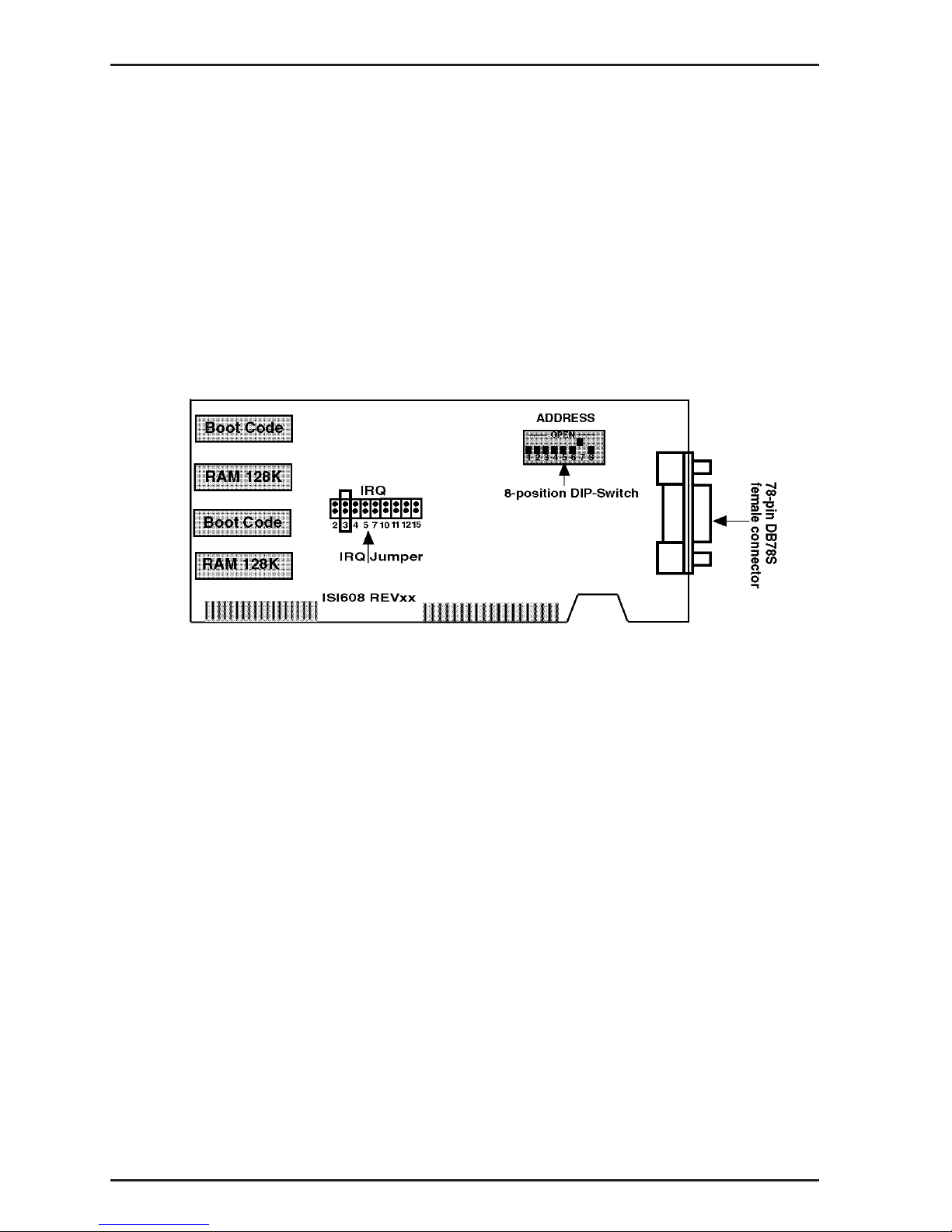
Figure 2-1. ISI4608 Board Components
4a The default setting for the ISI4608’s base I/O address is 210
hex. The default value for the IRQ jumper is IRQ 10. Choose
the IRQ value by covering the appropriate pins with the
shorting plug (supplied). Reference the diagram shown
above, if needed. If your system requires a different setting
or if you are installing multiple cards, refer to Appendix A for
a table of valid address settings.
Note: If you are installing the ISI4608 as a second card in a
MultiComRN
Gateway
(remote node gateway) the suggested
I/O address is 220 hex/IRQ11.
Record any changes you make to these settings and keep
them handy for the software installation section in Chapter 3.
Page 15
15
Chapter 2 - Installation
Step Procedure
5 Install the ISI4608 card(s) into the selected expansion slot(s)
in the same manner as any other add-on card, as instructed
in your computer’s documentation.
6 Fasten the retaining bracket to the computer chassis and
replace the cover.
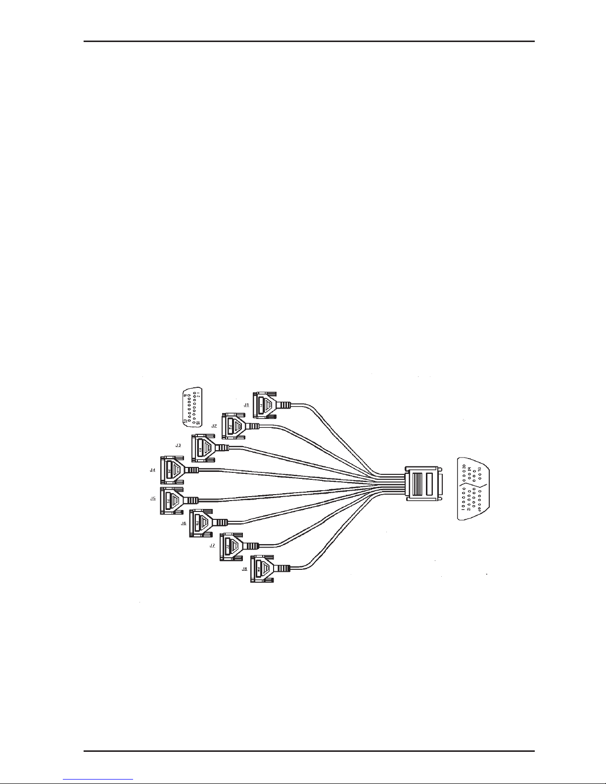
7 Attach the octopus cable to the DB78S female connector on
the ISI4608 card at the back of your computer. The RS232
ports provided by the octopus cable are for connection to
modems, multiplexers or other devices. If the other device is
a local terminal port, then a crossover cable is required (not
included) between the octopus cable and the terminal port.
See Appendix C for schematic of a crossover cable.
Note: Any cables connected to the computer must be
shielded to reduce interference.
Figure 2-2. Octopus Cable
Page 16

16
ISI4608 Owner's Manual
Step Procedure
8 Turn power on to the computer and refer to the manual that
was provided with the software you will be using with the
ISI4608 in order to perform software installation procedures.
Note: If the ISI4608 card is being used as an expansion card
(Remote Node--model #RNI08) for the
MultiComRN
Gateway
, then you must reconfigure the
gateway software, using the RASCON.EXE program. You
will need to add the card's settings to the Board Information
entry and assign access rights to each user under the User
Information entry. See Chapter Three of the
MultiComRN
Gateway
Owner's manual for server
configuration.
Page 17

Chapter 3 - Driver Installation
Page 18

18
ISI4608 Owner's Manual
Introduction
This chapter describes software/driver installation for the ISI cards
when used in Windows 2000, Windows NT4, Windows NT3.51,
Windows 95/98/Me, Novell, Linux, and SCO Open Server 5. We also
describe installation of MultiTech’s Management Software for use
with ISI cards under Windows 2000.
The process of installing a device driver consists of a modification to
your system. For this reason, only the "
super user
" (system
administrator) is allowed to perform the installation. If you cannot
login as the root, you must find the person in your organization who
has this authorization (i.e., password). To begin the driver
installation, login as root. Then go to the section of this chapter that
deals with the operating system you are using.
Installing ISI4608 Software for Windows
2000
1. Turn off the PC.
2. The ISI4608 card must already be installed in an ISA expansion slot in
the PC. If it is not, follow the PC manufacturer's instructions
concerning installation of expansion cards. Observe standard
precautions regarding electro-static discharge (ESD) when handling
the ISI4608 board (the board should be kept in its shipping bag until
used). During installation, handle the ISI4608 circuit card by its
edges and keep one hand in contact with the PC chassis. Set the
Base I/O Address and the Interrupt Request (IRQ) values per the
table below:
Recommended Base I/O Address and IRQ Values
ISI4608 Base I/O Address IRQ
Initial 8 port board 210h 10
First 8 port upgrade 220h 11
Second 8 port upgrade 230h 12
Third 8 port upgrade 240h 15
Page 19
19
Chapter 3 - Driver Installation
The I/O Address DIP Switch and the IRQ Jumper Block are at the
top middle of the ISI4608 circuit board and on the component side.
3. Turn on the PC and start Windows 2000.
4. Insert the ISI driver CD-ROM into the CD-ROM drive in the computer
(in cases where the driver files have been downloaded from the
MultiTech web site and copied onto diskette, insert the diskette into
the floppy drive now).
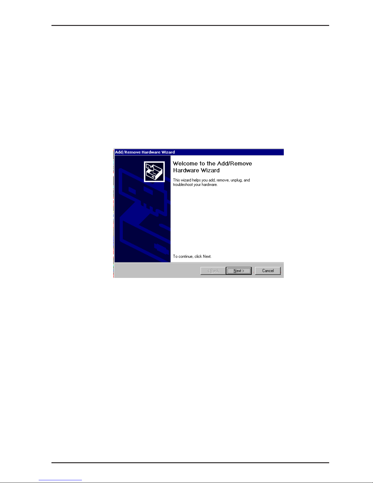
5. Go to Start | Settings | Control Panel | Add/Remove Hardware.
Click Next.
Page 20

20
ISI4608 Owner's Manual
6. At the Choose a Hardware Task screen, select "Add/Troubleshoot a
device."
Click Next.
7. At the Choose a Hardware Device screen, select "Add a new device."
Click Next.
Page 21
21
Chapter 3 - Driver Installation
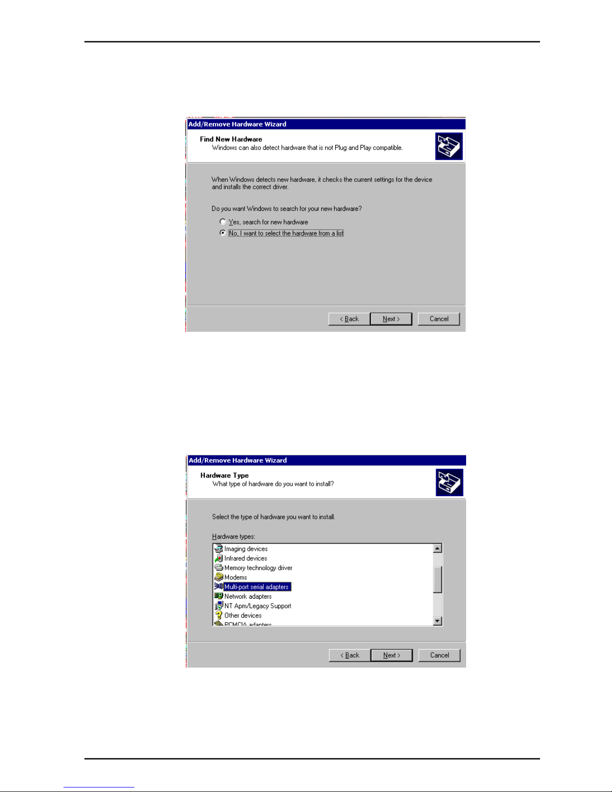
8. At the Find New Hardware screen, select "No, I want to select the
hardware from a list."
Click Next.
9. At the Hardware Type screen, select "Multi-port serial adapters."
Click Next.
Page 22
22
ISI4608 Owner's Manual
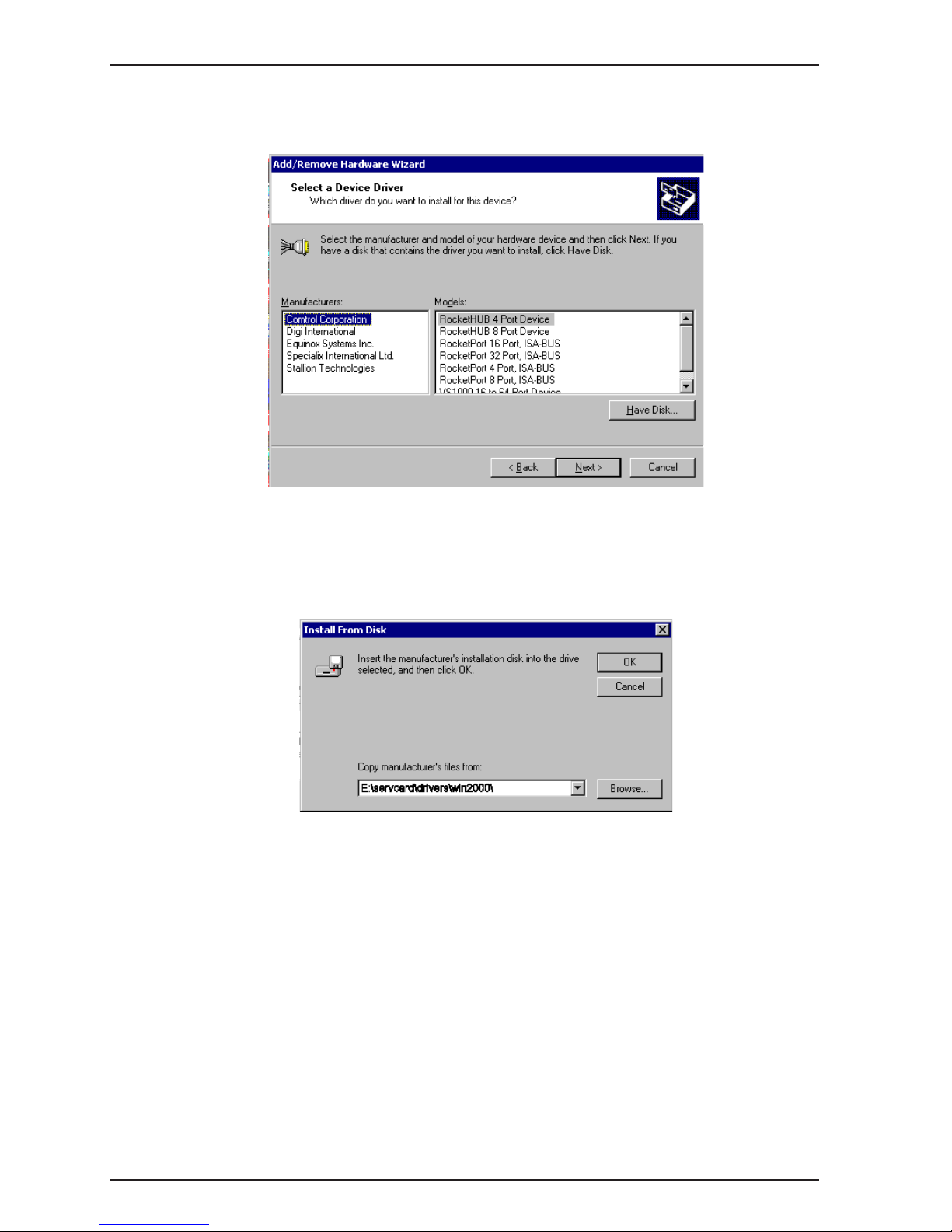
10. At the Select a Device Driver screen, click on Have Disk.
11. At the Install from Disk screen, enter the pathof the driver files (i.e.,
the file directory location, in most cases on CD-ROM).
Click OK.
Page 23
23
Chapter 3 - Driver Installation
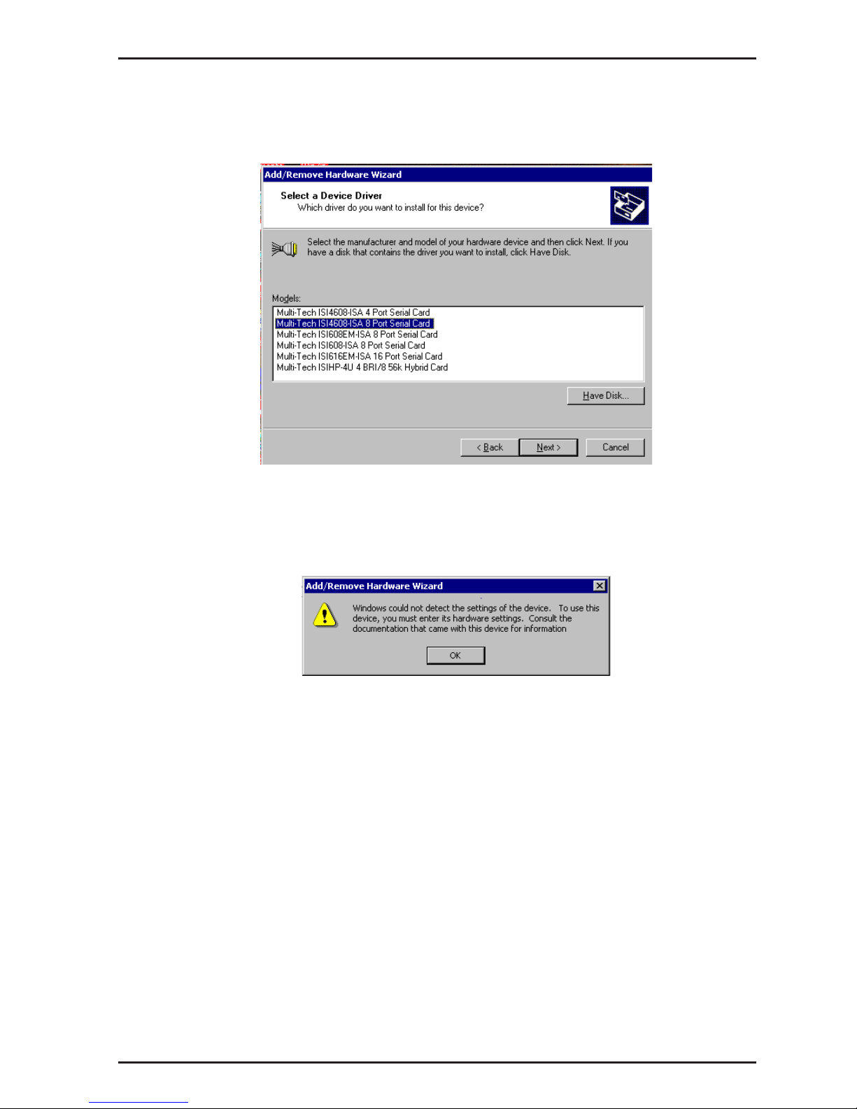
12. In the Models list, highlight "Multi-Tech ISI4608-ISA 8 Port Serial
Card."
A comment screen appears indicating that the Base I/O Address and
IRQ must be specified for the ISI4608 card.
Click OK.
Page 24
24
ISI4608 Owner's Manual
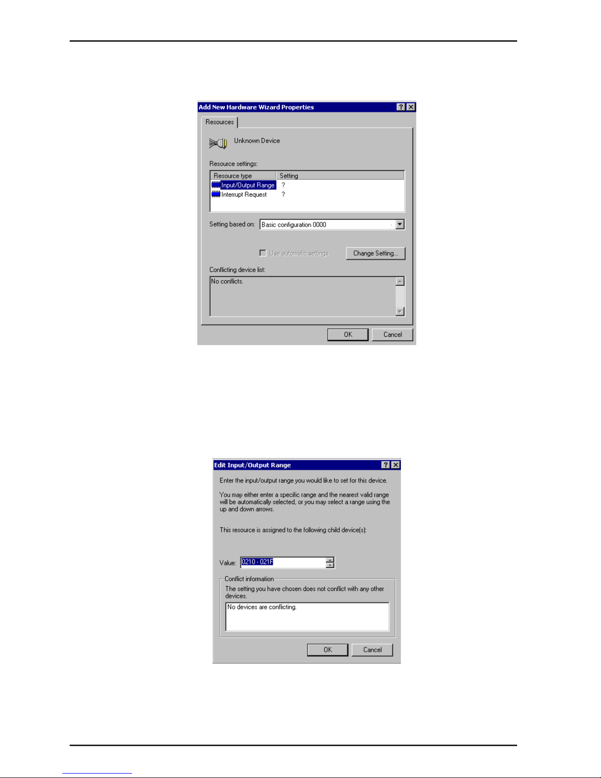
13. The Add New Hardware Wizard Properties screen appears.
A. In the Resource Settings field, select "Input/Output Range" and
click on Change Setting. The Edit Input/Output Range screen
appears.
Select the value that matches the Base I/O Address value that you
have already set on the ISI4608 board in Step 2. Click OK.
Page 25

25
Chapter 3 - Driver Installation
B. In the Resource Settings field, select "Interrupt Request" and click
on Change Setting. The Edit Interrupt Request screen appears.
Select the value that matches the IRQ value that you have already
set on the ISI4608 board in Step 2. Click OK. At the Resources tab,
click OK again.
14. At the Start Hardware Installation screen, click Next.
Page 26

26
ISI4608 Owner's Manual
15. A completion screen appears.
Click Finish.
16. You will be prompted to restart your computer. Click Ye s.
Page 27

27
Chapter 3 - Driver Installation
ISI4608 for Windows 2000: Installing ISI Management Software (server OSs only)
If you are using a Windows 2000 Server operating system ("Server" or
"Advanced Server"), you must decide whether you want to use the
MultiTech ISI Management Software in conjunction with your ISI4608
board. The ISI Management Software is shipped with the ISI card.
1. Turn on your computer and start Windows 2000.
2. Insert the CD-ROM containing the ISI Management Software into
your CD-ROM drive. (If ISI Management Software has been
downloaded from the MultiTech web site, it will typically be on a
diskette. In that case, insert diskette into floppy drive).
3. Go to Start | Run. In the Run window, enter the file path of the ISI
Management software. Typically, this would be
E:\SERVCARD\UTILITY\MGMT\SETUP.EXE.
Click OK.
4. The ISI Management setup screen appears. At the Welcome screen,
click Next.
5. A progress screen appears while files are copied. If the Error
Creating WWW Server message appears, it may indicate that there
was an attempt to install the ISI Management Software on a client
version of Windows 2000. (The ISI Management Software can be
installed only in the Windows 2000 Server and Windows 2000
Advanced Server operating systems.)
Page 28

28
ISI4608 Owner's Manual
6. A completion screen appears.
Select "Yes, I want to restart my computer now" and click Finish.
After the computer has restarted, the installation of the driver and of
the ISI Management Software will be complete.
Remove ISI4608 Driver (Windows 2000)
1. Go to Start | Settings | Control Panel.
2. Click on Add/Remove Hardware. Click Next.
3. Click on Uninstall/Unplug a device and click Next.
4. In the subsequent screen, click on Uninstall a device and click
Next.
5. At the Add/Remove Hardware Wizard screen, highlight the ISI driver
file for the specific server card that you intend to remove. Click
Next.
6. When you are asked to confirm removal, click on the Yes radio
button and click Next.
7. Click Finish. You can remove the driver for only one ISI4608 card at
a time.
Page 29

29
Chapter 3 - Driver Installation
ISI4608 Software Installation Procedure for
Windows NT 3.51/4.0
1. Turn off the PC.
2. The ISI4608 card must be installed in an ISA-type expansion slot
in the PC. If not, follow the PC manufacturer's instructions
concerning installation of expansion cards. Observe standard
precautions regarding electro-static discharge (ESD) when handling
the ISI4608 board (the board should be kept in its shipping bag until
used). During installation, handle the ISI4608 circuit card by its
edges and keep one hand in contact with the PC chassis.
Recommended Base I/O Address and IRQ Values
ISI4608 Base I/O Address IRQ
Initial 8 port board 210h 10
First 8 port upgrade 220h 11
Second 8 port upgrade 230h 12
Third 8 port upgrade 240h 15
The I/O Address DIP Switch and the IRQ Jumper Block are at the
top middle of the ISI4608 circuit board and on the component side.
3. Turn on the PC and start Windows NT4.0.
4. Insert the driver CD-ROM into the CD-ROM drive. (If drivers
were obtained from MultiTech web site and stored on diskette, place
diskette into floppy drive now.)
5. Click Start | Settings | Control Panel | Network | Adapters. Then
click Add.
6. The Select Network Adapter dialog box appears. Click Have
Disk.
7. The Insert Disk dialog box appears. Type or browse for the path
(file directory location) of the Windows NT driver (for example,
E:\SERVCARD\DRIVERS\WINNT\SETUP.EXE). Click OK.
Page 30

30
ISI4608 Owner's Manual
8. The Select OEM Option dialog box appears. Click OK.
A transient dialog box will appear indicating the progress of the
setup program.
9. The ISI Cards dialog box appears. Click Add.
Page 31

31
Chapter 3 - Driver Installation
10. Then the ISI Card Settings dialog box appears. Enter the
correct port count: allocate 8 ports for each ISI4608 card. Select the
first port number for ISI modems, which is usually COM3.
Click "ISA" in the Bus Type field. Enter the Base I/O Address and
IRQ as in Step 2 above.
11. The ISI Cards dialog box appears again and shows the port
resource allocation just made. To add more cards, click Add and
repeat Step 9.
After the last ISI card has been added, click Close.
Page 32

32
ISI4608 Owner's Manual
12. The file is copied and "Multi-Tech 4, 8, 16-port ISI Card" appears
in the Network Adapters box. Click Close.
13. When prompted about restarting your computer, click Ye s .
The ISI4608 card software is now installed in Windows NT.
Removing ISI4608 Card and Driver in Windows NT 3.51/4.0
1. Go to Start | Settings | Control Panel | Network. Click on the
Adapters tab.
2. Select "MultiTech 4, 8, 16-port ISI card," and then click Remove.
To complete the un-install procedure, restart your computer.
Page 33

33
Chapter 3 - Driver Installation
ISI4608 Software Installation Procedure
for Windows 95/98/Me
1. Turn off the PC.
2. The ISI4608 card must be installed in an ISA-type expansion slot
in the PC. If not, install the ISI4608 card in an available ISA
expansion slot following the PC manufacturer's instructions
concerning installation of expansion cards. Observe standard
precautions regarding electro-static discharge (ESD) when handling
the ISI4608 board (the board should be kept in its shipping bag until
used). During installation, handle the ISI4608 circuit card by its
edges and keep one hand in contact with the PC chassis.
Set the Base I/O Address and the Interrupt Request (IRQ) values
per the table below:
Recommended Base I/O Address and IRQ Values
ISI4608 Base I/O Address IRQ
Initial 8 port board 210h 10
First 8 port upgrade 220h 11
Second 8 port upgrade 230h 12
Third 8 port upgrade 240h 15
The I/O Address DIP Switch and the IRQ Jumper Block are at the
top middle of the ISI4608 circuit board and on the component side.
3. Turn on the PC and start Windows 95/98/Me.
4. Insert MultiTech ISI driver CD-ROM into the CD-ROM drive. (If
drivers were downloaded from the MultiTech web site and placed
on diskette, insert diskette into floppy drive now.)
Page 34

34
ISI4608 Owner's Manual
5. (Follow either 5A or 5B, but not both.)
A. From Windows Explorer, open the 95-98-ME directory on the
CD-ROM or floppy drive that contains the ISI driver file (for
example, E:\SERVCARD\DRIVERS\95-98-ME\). Highlight the file
setup.exe.
B. From the Start menu, go to Run. Browse to the path of the
95-98-ME directory.
6. Launch the setup program. (From Windows Explorer, double-click on
setup.exe; from the Run menu, click OK.)
7. The installation wizard will begin running. At the Welcome screen,
click Next.
Page 35

35
Chapter 3 - Driver Installation
8. Under Select Type of Card, check the Install ISA Card box. Click
Next.
9. Specify the number of ports on the card as 8.
Page 36

36
ISI4608 Owner's Manual
10. A message screen appears.
Click OK.
11. A completion screen appears.
Click OK.
12. The System Properties | Device Manager screen appears. Highlight
MultiTech ISI Card. Click Properties.
Page 37

37
Chapter 3 - Driver Installation
13. The MultiTech ISI Card Properties screen appears.
Click on the Resources tab.
14. Click on Set Configuration Manually.
Page 38

38
ISI4608 Owner's Manual
15. Set the "Input/Output Range" to match the Base I/O Setting
that you specified on the hardware DIP switch in Step 2 above. Set
the "Interrupt Request" to match the IRQ setting you specified on
the hardware jumper block in Step 2 above. To alter these parameters, click on the Change Setting button.
16. When editing of IRQs and Base I/O Address settings is
complete, click OK. Then click OK at the Resources screen.
The System Settings Change screen appears.
17. When prompted about re-starting your computer, click Yes .
18. When the computer is restarted, the software installation will be
complete.
Page 39

39
Chapter 3 - Driver Installation
Removing the ISI4608 Driver (Windows 95/
98/Me)
1. Click Settings, Control Panel, and then double-click Add/Remove
Programs.
2. From the list box, select MultiTech ISI Driver Device.
3. Click Add/Remove and follow screen instructions.
NetWare Driver Installation
Multi-Tech Systems provides AIO drivers for the ISI4608 cards, so
they can function with Novell compatible asynchronous applications
(e.g., NetWare Connect). The AIO driver is simply an NLM (NetWare
Loadable Module) that runs on the file server. Drivers must be loaded
on the file server where the board is installed. Drivers can be loaded
from the file server’s console prompt or incorporated for autoloading
in the AUTOEXEC.NCF file.
The file AIOMTS.MDC contains Novell (version 3.12 and higher)
initialization strings for ISI products not previously listed for use with
BorderManager and NetWare Connect. The file AIOMTS.MDC is
included on the ISI Product Family CD. To benefit from the
AIOMTS.MDC file, you must copy it from the CD to the appropriate
directory on your computer.
To use AIOMTS.MDC under BorderManager, RAS, NIAS in 4.2 or 5.x:
Copy AIOMTS.MDC to your System directory.
To use AIOMTS.MDC under Novell NetWare 3.x, 4.1, 4.11 with
Netware Connect 2.028 or higher:
Copy AIOMTS.MDC to your System and System/AIO directories.
To install the Multi-Tech AIO driver, copy the file
AIOISIX.NLM
to the
system directory of the file server from a workstation on the network.
To copy, you can use the following command:
Page 40

40
ISI4608 Owner's Manual
COPY E:\SERVCARD\DRIVERS\NOVELL\AIOSIX.NLM F:\SYSTEM
If you have downloaded the ISI driver from the MultiTech web site
onto a diskette, use this command:
COPY A:\NOVELL\AIOISIX.NLM F:\SYSTEM
To load the driver, go to the system or PC console (where the ISI card
is installed) and enter the following at the prompt:
LOAD AIOISIX [port=W] [interrupt=X] [name=Y] [note=Z]
The I/O Address DIP Switch and the IRQ Jumper Block are at the top
middle of the ISI4608 circuit board and on the component side.
To install the ISI card scripts, copy aiomdms.mdc to
f:\system\aio\directory. Click Yes to overwrite the existing
aiomdms.mdc file.
Configuring Ports for NetWare Connect
When the driver is installed, it will allocate 8 consecutive COM ports
for the ISI4608 card.
To set up NetWare Connect ports, enter LOAD NWCCON at the
NetWare console prompt. LOAD NWCCON opens the NetWare
Connect Configuration Utility. Select the appropriate menu options
(modem type, speed, flow control, etc.).
Removing the Driver (Novell)
In Novell, remove file AIOISIX.NLM from the system directory and
make the appropriate changes to the
Autoexec.ncf
file.
Error Messages
1.
*Error: An ISI4608 does not seem to appear at
address X*
This means that the driver could not find the ISI4608
residing at the address X. Make sure that there is no other
device in your system at the same I/O address. Make sure
that the ISI4608 is seated properly in the system slot.
Page 41

41
Chapter 3 - Driver Installation
2.
*Error: ISI4608 rejected the load header*
*Error: ISI4608 got out of sync*
*Error: ISI4608 verify failed at address X*
*Error: Expected X received Y*
*Error: Verify got out of sync*
All the above errors represent problems with the file server not being
able to communicate with the ISI4608. Make sure that you do not
have any other device residing in the system at the same I/O address
you have chosen for the ISI4608. Power down the server, make sure
that the ISI4608 is seated properly in the system slot. Power up the
file server and try to load the AIO driver again. If the problem persists,
contact the Multi-Tech Technical Support team.
SCO Open Server 5 Driver Installation
The ISI driver for SCO Open Server 5 is shipped on CD-ROM (FAT file
system) and can also be downloaded from the Multi-Tech web site.
In both cases, the driver files are compressed (“tarred”). Users
installing from the CD-ROM should begin at “To install from CDROM” directly below. Users installing from a floppy disk should skip
down to “To install driver from floppy disk” later in this section. The
filename of the SCO5 driver in its tarred form is sco50x.tar.
This present installation section is task-oriented with minimal
explanation of procedural steps. The section
Multi-Tech Installation
Script,
which immediately follows this section, presents additional
details to aid in installation.
To install from CD-ROM:
# mount -r /dev/cd0 /mnt
# cd /mnt
# cd servcard/drivers/sco50x
#cp sco50x.tar /
# cd <ENTER>
Page 42

42
ISI4608 Owner's Manual
To format a floppy disk for SCO5:
1. At the Unix prompt, run the scosh program.
2. Select Manager.
3. Select Archive.
4. Select Format.
5. Make sure that Device is pointed to the floppy drive.
6. Select Continue.
To untar the driver file and copy files onto floppy disk:
1. Make a temporary directory for the ISI driver files..
# mkdir /isi
2. Copy the tarred isi driver file into the temporary directory.
# cp sco50x.tar /isi
3. Untar this file and put its contents into the temporary directory.
# cd /isi
# tar xvf sco50x.tar
4. Copy the untarred (inflated or non-compressed) files to a floppy
disk
# cd /isi/unifiedinstimg301
#scosh
- Select Manager.
- Select Archive.
- Select Create.
- Press space bar to highlight tmp/ and usr/ directories.
- Press <ENTER> to copy.
- Make sure Device is pointed to the floppy disk.
- Make sure that the “Type” is cpio.
Page 43

43
Chapter 3 - Driver Installation
- Select Continue.
5. To verify that the files have been copied onto the floppy disk, use
these commands:
# scosh
- Select Manager.
- Select Archive.
- Select List.
- Make sure Device is pointed to the floppy disk.
- Select Continue.
To install driver from floppy disk
(Users starting with the untarred SCO5 driver on a floppy disk can
begin the installation here).
1. Run the custom utility.
2. Select Software.
3. Select Install New.
4 Highlight driver file from local host and select Continue.
5. Select as the Media Device “Floppy Disk Drive.”
6. Select Continue.
7. Highlight “Multi-Tech ISA/PCI ...” and select Install.
8. Enter Y (yes) to continue installing the ISI driver.
9. As many as four ISI4608 cards can be installed in the server.
Type 1, 2, 3, or 4, based on the number of ISI4608 cards you are
installing in your system. Type the base I/O address and the IRQ
value for each card. Be sure that the I/O address and the IRQ value
match the values set in the DIP switch and jumper block on the
ISI4608 card. (The I/O Address DIP Switch and the IRQ Jumper
Block are at the top middle of the ISI4608 circuit board and on the
component side.)
Page 44

44
ISI4608 Owner's Manual
For further details see
MultiTech Installation Script
step 1.
10. For the number of pseudo-devices to be created, type 8.
For further details see
MultiTech Installation Script
step
2.
11. Type Y (yes) to accept the prefix for tty ports. For further details
see
MultiTech Installation Script
step 3.
12. Type Y (yes) to confirm the selection. For further details see
MultiTech Installation Script
step 4.
13. After the driver is installed, press <Enter> to continue. For further
details see
MultiTech Installation Script
step 4 (last paragraph) and
step 5.
14. Exit the custom utility. For further details see
MultiTech
Installation Script
step 6.
15. Remove the floppy disk and reboot your computer. For further
details see
MultiTech Installation Script
step 7.
MultiTech Installation Script
The Multi-Tech Installation Script for SCO Open Server 5 systems
requests information about how many boards you want to install,
designations for communication ports and printer ports, and how
many pseudo devices you want to create for Multi_View utility. Based
on this information, the appropriate driver files will be installed and
linked with your system’s kernel.
1. This text appears on the screen:
You can install up to 4 ISA/PCI cards in a
system. The PCI cards will be autodetected on
bootup. Enter the number of ISA cards you
want to install and configure on your system
(0-4).
Select 0 if your computer has a PCI bus. This tells the SCO
operating system to autodetect the ISI cards.
For ISA-bus cards like the ISI4608, type 1, 2, 3, or 4, depending on
how many cards you want to install in the computer.
Page 45

45
Chapter 3 - Driver Installation
2. The following text appears on the screen:
Multi_View is a utility which will allow you
to have multiple sessions on terminals that
have multiple pages of physical memory. In
order for this utility to work with
MultiTech’s serial cards, pseudo devices have
to be created in your /dev directory. These
devices are system-wide resources.
Enter the number of pseudo-devices to be
created for the use of Multi_View utility
(1 - 256).
The Multi_View utility initializes the multiple-page capability of
terminals with multiple pages of memory. The number specified here
is the total number of devices (between 1 and 256) available to all
Multi-Tech terminals and its the number of pseudo devices
available to the Multi_View utility.
Specify 8 pseudo devices for each ISI4608 card installed.
For example, if the computer contains three ISI4608 cards, you
would enter 24.
You must initialize each of the eight ports separately using the
enable command (for example, enable ttyl1a).
3. This text appears on the screen and relates to the /dev directory.
This script also creates the devices in your
system to communicate with the ports of
ISICOM. The default prefix for the tty ports
is ttyl. The default prefix for the printer
is prnl. Is this acceptable? (y/n/q).
For most users, its best to select y, which entails accepting the
default values. Then proceed to step 4.
Details for use of non-default port/printer values. The /dev
directory holds device-information files used by the kernel to access
the hardware. When you add an ISI card, you must give the ISI
ports unique names so they do not conflict with existing ports or
Page 46

46
ISI4608 Owner's Manual
with other devices known to your system. If a device name has
already been assigned to an existing device and the operator
assigns that name to a new device, then the existing device will be
deleted when the ISI port using its name is created.
a. To use a non-default base name, type N and then enter a
basename having less than five characters. The base name you
select will be used for all ports on each card you install. ISI port
designations will have this form:
[basename prefix][board number][port letter].
basename: Length is one to four characters.
board number: Values will be 1, 2, 3, or 4, depending on
how many ISI cards are installed in your computer.
port letter: For ISI4608, use letters A through H for modems.
(For terminal control devices, use lower-case letters as port
identifiers.)
Device basename selected: _________________
b. After you select a device basename, you are prompted for a printer
base name. This prefix identifies each port that supports a terminal
with a printer attached to its auxiliary port (for transparent printing).
Specify a unique printer base name (printer parameters are outlined
in the Multi_Setup Utility section in this manual ).
Printer base name selected: _________________
When you have specified the device base name and the printer base
name, press Enter to continue.
4. The confirmation screen lists the values you have selected. The
following text appears on the screen (default values are shown):
You have chosen the following setup
The tty prefix is ttyl.
The printer prefix is prnl.
Number of Multi_View pseudo devices
[
user-specified number
].
If these values are correct, type Y and the installation process will
continue. If there is an error in any of the values displayed, type N
Page 47

47
Chapter 3 - Driver Installation
and the first screen displays. Then re-enter the information for each
card.
When you accept the confirmation list (by typing Y), a series of
messages displays while the driver is being installed and the kernel
rebuilt. After the terminals have been added to the Terminal Control
database, and when the display says Press <Enter> to
continue:, then press ENTER. When Installation
complete displays, press ENTER again.
5. Select Host and press ENTER . Remove the diskette from the
drive.
6. Select Exit and press ENTER .
7. To reboot the system (required), enter the following commands:
Type shutdown -g0-y and press ENTER
OR
Type init 6 and press ENTER .
Driver installation for the ISI card now is complete.
Activating Ports in SCO Open Server 5
SCO Open Server 5 provides a device database that monitors the
activity of serial ports through which users can log onto the host. If
your ISI ports are used by terminals (e.g., to allow users to log onto
your host), you must create an entry in the system’s device database
that furnishes specific information for the terminals that will be used
on each ISI port. The database is referenced each time a user
attempts to log in. If there is no database entry for a particular
terminal, access to the host is denied.
1. Turn on your system and verify that the firmware for each ISI4608
loads successfully. If the firmware for a given ISI4608 card does not
load, none of its ports will be accessible. (If this happens, see
Multi-Techs Administrative Utility section in this manual.)
2. Type the complete name of the first device you want to create in
usr/lib/uucp/Devices. Substitute the specific base
name, board number, and port letter for the generic parameters in the
expression ttylbx. Use a lower-case x value for local DTE
(terminal) support and an upper case X value for modem control for
each port you want to enable. Example: ttyl2A denotes the
Page 48

48
ISI4608 Owner's Manual
second ISI card (2) and the first port on that card (A). The port
status can be altered later, but one setting must be selected at this
time. The ACU line would read as follows:
ACU ttylbX - 9600 dialer name. Replace b, X and
dialer-name with appropriate values.
3. Repeat this process for each port on each board you have installed.
Record the setting you select for each port.
4. Using device names created in the previous section, type the
following command for each port you want to activate: enable ttylbx
5. Repeat this command for each port you want to activate, using the
lower case letter for local terminal use or upper case for modem
control.
Note: Only one of the options (e.g., modem control or local
terminal access) should be enabled for any port at one time. For
example, you cannot enable
ttyl1a
and then enable
ttyl1A
.
To change the status of a port, disable the current status
(
disable ttyl1a
) and then enable it for the desired status
(
enable ttyl1A
).
Removing the Driver (SCO Open Server 5)
To remove the Multi-Tech Serial Card Driver, enter the configuration
utility (e.g., custom for SCO Open Server 5) and follow instructions to
remove the entire driver and rebuild the kernel without the ISI driver. If
it is necessary to reinstall the driver due to I/O address or IRQ
overlap, remove the driver first.
Note: Remove the driver before permanently removing the ISI card from the
computer.
Page 49

49
Chapter 3 - Driver Installation
Linux Driver for Multi-Tech ISI Server Cards
LINUX: Pre-Installation Issues
When unpacking the Linux driver, there are two choices, one driver
for the 2.0.x kernel (at this writing, it is filename L300_20X.TAR), and
one driver that works for both the 2.2.x kernel and the 2.4.x kernel (at
this writing, it is filename L305_22X_24X.TAR) Be absolutely positive
about which kernel you have! Note that updated driver files may be
issued from time to time.
The 'make' utility, GNU C compiler, and the kernel sources need to be
installed on your system. If any of these are missing, the compilation
will fail. Most later Linux OSs install these elements automatically .
LINUX: Copying the driver from the media
The Linux drivers (for 2.0 and 2.2/2.4 kernels) are shipped in
compressed (‘tarred’) form on a CD-ROM formatted with the FAT file
system. In some cases, users may download Linux ISI drivers from
the MultiTech web site onto diskette (in ext2 format). We present
instructions for both situations below.
LINUX: Copying and untarring the driver from CDROM
1. Mount the CD-ROM using this command:
mount /mnt/cdrom
2. Change directory
cd /mnt/cdrom
3. List the files on the CD-ROM and locate the directory for the kernel
in use (2.0 or 2.2/2.4), using this command
ls
4. Untar the appropriate Linux driver using this command:
> tar vxf
{filename}
/tmp
Page 50

50
ISI4608 Owner's Manual
At this writing, the filename will be either L300_20X.TAR (for 2.0
kernel) or L305_22X_24X.TAR (for 2.2/2.4 kernel).
LINUX: Copying and untarring the driver from a
floppy
The ISI driver
.tar
file can be copied from a DOS formatted floppy
using the 'mcopy' command if the 'mtools' have been installed. Issue
'mcopy a:isilinux.tar <destination folder>' to copy the isilinux.tar ( or
current driver name) file to the destination folder. As an alternative,
the floppy can be manually mounted and the file copied to the
required destination folder.
NOTE: To read from a DOS formatted floppy, a kernel with support for the
FAT file system (either statically linked in the kernel or as modules) is
required.
Steps for copying the driver from a floppy:
1. Linux floppy disks are in ext2 format.
2. Insert Linux driver in drive A: and mount floppy drive.
> mount -t ext2 /dev/fd0 /mnt/floppy
3. Copy files from floppy to a temporary directory on hard drive.
> mkdir /isi
> cd /isi
> cp /mnt/floppy/kernel_2.2.x/* /isi
After you have copied the installation tar file to a folder, use the
command 'tar xvf isilinux.tar' to untar (unzip or de-compress) the
installation files in that folder.
LINUX: Driver installation and loading
Execute the 'Install' script to build the driver and to copy the driver and
firmware files to the required folder.
> cd /isi
> ./Install
Page 51

51
Chapter 3 - Driver Installation
For ISI4608, which are equipped with the ISA-type bus, the
installation script requires the user to type in the I/O address and the
IRQ to be used. The installation creates the script file 'ISICOMStart' in
the destination folder. 'ISICOMStart' automates the loading process
for the driver and firmware.
To view busy I/O address space on your system, enter
cat/proc/ioports
To view busy IRQs, enter:
cat /proc/interrupts
You must load the driver before you can load the firmware. You can
load the driver manually using the 'insmod' utility. For ISI4608 cards
which are equipped with the ISA-type bus, the I/O base address and
the IRQ required by the card also need to be passed as parameters
to insmod (this does not apply to ISI cards with the PCI bus). The I/O
Address DIP Switch and the IRQ Jumper Block are at the top middle
of the ISI4608 circuit board and on the component side.
insmod isicom io=card1, ... card4 irq=card1, ... card4
The PCI cards and their configurations will be auto-detected by the
driver.
You can manually load the firmware into all of the installed ISI cards
simultaneously by executing the 'frmld' utility in the installation folder.
The firmware to all the installed cards can be manually loaded by
executing the 'firmld' utility in the installation folder. This utility
requires the firmware files (.bin) to be located in the /usr/local/
ISICOM/ folder.
LINUX: Setting the baud rate
The 'stty' utility can be used to set the baud rate of a particular port.
For example, to set the baud rate of the first port on the first card
(ttyM1a) to 38400 bps, execute 'stty 38400 < /dev/ttyM1a'.
The current baud rate can be viewed by executing 'stty < /dev/ttyM1a'.
Page 52

52
ISI4608 Owner's Manual
LINUX: Verifying the ports
Terminal utilities like 'minicom' can be used to verify the ports,
'talk' to the modem, and dial out.
To configure 'minicom' for a particular port, run it with the '-s'
option. In the 'serial port setup' menu option, set the serial device to
the required ISI port device (for example, '/dev/ttyM1a' for the first
port on the first card). Save the configuration for a particular port
using the 'save setup as' menu option as, for example, '1a' for the
port /dev/ttyM1a. To connect to the port /dev/ttyM1a using minicom the
next time, 'minicom 1a' needs to be executed.
LINUX: TTY Devices Created by the Drivers:
Device files corresponding to ports on the ISI card are created in
the /dev folder. Use ttyMxy for normal ports and cumxy for
corresponding callout ports. Normal ports (ttyM) are configured for
dial-in connections. Callout ports (cum) are used for dial-out
connections.
In these expressions (ttyMxy and cumxy), the letter x is the
card number (1-4), and y is the port designator (a, b, c, ...).
The ISI Linux driver creates the following TTY devices in /dev
directory:
- /dev/ttyM1a TO /dev/ttyM1p for the first ISI card
- /dev/ttyM2a TO /dev/ttyM2p for the second ISI card
- /dev/ttyM3a TO /dev/ttyM3p for the third ISI card
- /dev/ttyM4a TO /dev/ttyM4p for the fourth ISI card
For 8-port cards, like the ISI4608, it uses the following:
- /dev/ttyM1a TO /dev/ttyM1h for the first ISI card
- /dev/ttyM2a TO /dev/ttyM2h for the second ISI card
- /dev/ttyM3a TO /dev/ttyM3h for the third ISI card
- /dev/ttyM4a TO /dev/ttyM4h for the fourth ISI card
Page 53

53
Chapter 3 - Driver Installation
Devices mapped for ISI4608 cards):
For the ISI4608 card (8 ports):
- /dev/ttyM1a to /dev/ttyM1h
should be mapped for modem ports.
LINUX -- Dial-in configuration:
To configure a particular port for dial-in, utilities like 'mgetty' need to
be installed on the system. If, for example, the port /dev/ttyM2c needs
to be configured for a remote-access dial-in connection, an entry of
the form 'M2c:12345:respawn:/sbin/mgetty ttyM2c' needs to be added
in the /etc/inittab file. After you have made the change, execute 'init q'
so that the 'init' process re-reads the inittab file and spawns the
mgetty process to wait for an incoming connection. Users can then
dial in, use their user names and passwords to log in, and access
their accounts on the machine.
To disable dial-in access on a particular port, change the entry in the
/etc/inittab file to 'M2c:12345:off:/sbin/mgetty ttyM2c'or just commentout that entry by prefixing a '#' to the entry on the line.
LINUX -- PPP setup:
The 'PPP-HOWTO' (a document that is available as a part of the
'HOWTO' documentation on most of the distributions under /usr/doc/
HOWTO) explains in detail the procedure for configuring a Linux
machine as a PPP server. This information is also available at
http://www.interweft.com.au/other/ppp-howto/ppp-howto.html.
The documentation in the PPP-HOWTO is directly applicable to ISI
ports.
Note: A base I/O address of 0, e.g., ISIBaseX=oxo, or omission of these
parameters for any card X, disables that particular card.
Miscellaneous:
Device files corresponding to ports on the ISI4608 cards are created in the
/dev folder. Use ttyMxy for normal ports and cumxy for corresponding
callout ports. The letter x is the card number (14), and y is the port
Page 54

54
ISI4608 Owner's Manual
number, (ah) for 8-port cards.
Normal ports (ttyM) are configured for dial-in connections. Callout ports
(cum) are used for dial-out connections.
To view busy I/O address space on your system, enter:
cat /proc/ioports
To view busy IRQs, enter:
cat /proc/interrupts
To load the driver manually, use insmod.
Example: To load two ISI cards configured with base I/O addresses 0x210
and 0x200 and IRQs 5 and 10, enter the following in the destination folder:
insmod isicom
ISIBase1=0x210
Irq1=5
ISIBase2=0x200
Irq2=10
To remove the driver manually, enter rmmod isicom. This removes the
driver only if no ISI ports are in use.
Removing the ISI Driver (Linux)
1. Type cd /usr/local. Press ENTER.
2. Type rm -r ISICOM. Press ENTER.
3. This will remove driver for all ISIHx cards in that Linux server.
4. Remove the isictl file by typing rm isictl in the /dev directory.
5. Remove all devices that start with ttyM1x, ttyM2x, ttyM3x and ttyM4x
in the /dev directory.
rm ttyM1*
rm ttyM2*
rm ttyM3*
rm ttyM4*
Page 55

Chap 4: Warranty, Service & Tech Support
Page 56

56
ISI4608 Owner's Manual
Warranty, Service & Tech Support
Limited Warranty
Multi-Tech Systems, Inc., (hereafter “MTS”) warrants that its products
will be free from defects in material or workmanship for a period of
two, five, or ten years (depending on model) from date of purchase, or
if proof of purchase is not provided, two, five, or ten years (depending
on model) from date of shipment.
MTS MAKES NO OTHER WARRANTY, EXPRESS OR IMPLIED, AND
ALL IMPLIED WARRANTIES OF MERCHANTABILITY AND FITNESS
FOR A PARTICULAR PURPOSE ARE HEREBY DISCLAIMED.
This warranty does not apply to any products which have been
damaged by lightning storms, water, or power surges or which have
been neglected, altered, abused, used for a purpose other than the
one for which they were manufactured, repaired by Customer or any
party without MTS’s written authorization, or used in any manner
inconsistent with MTS’s instructions.
MTS’s entire obligation under this warranty shall be limited (at MTS’s
option) to repair or replacement of any products which prove to be
defective within the warranty period or, at MTS’s option, issuance of a
refund of the purchase price. Defective products must be returned by
Customer to MTS’s factory — transportation prepaid.
MTS WILL NOT BE LIABLE FOR CONSEQUENTIAL DAMAGES, AND
UNDER NO CIRCUMSTANCES WILL ITS LIABILITY EXCEED THE
PRICE FOR DEFECTIVE PRODUCTS.
Addendum for North American Products
In the event that service is required, products may be shipped, freight
prepaid, to our Mounds View, Minnesota, factory (Multi-Tech Systems,
Inc., 2205 Woodale Drive, Mounds View, MN 55112, Attn: Repairs,
Serial #_____). A Returned Materials Authorization (RMA) is not
required. Return shipping charges (surface) will be paid by MTS.
Please include, inside the shipping box, a description of the problem,
a return shipping address (must have street address, not P.O. Box),
a telephone number, and if the product is out of warranty, a check or
purchase order for repair charges.
Extended two-year overnight replacement agreements are available
for selected products. Please refer to our Overnight Replacement
Agreement for details on rates and coverages.
Page 57

57
Chapter 4 - Warranty, Service and Tech Support
Please direct your questions regarding technical matters, product
configuration, verification that the product is defective, etc., to our
Technical Support department at 1-800-972-2439. Please direct your
questions regarding repair expediting, receiving, shipping, billing,
etc., to our Repair Accounting department at (800) 328-9717 or (763)
717-5631.
Repairs for damages caused by lightning storms, water, power
surges, incorrect installation, physical abuse, or user-caused
damages are billed on a time-plus-materials basis.
Addendum for International Products
Distributors should contact Amex, Inc., for information about the
repairs for your Multi-Tech product.
Amex, Inc.
2724 Summer Street NE
Minneapolis, MN 55413 U.S.A.
Tel: +(612) 331-3251
Fax: +(612) 331-3180
Please direct your questions regarding technical matters, product
configuration, verification that the product is defective, etc., to our
Technical Support department nearest you. When calling the U.S.,
please direct your questions regarding repair expediting, receiving,
shipping, billing, etc., to our Repair Accounting department at +(763)
717-5631 in the U.S.A., or a nearby Multi-Tech office which is listed
on the “Multi-Tech Corporate Offices” sheet in this International
Distributor Resource Kit.
Repairs for damages caused by lightning storms, water, power
surges, incorrect installation, physical abuse, or user-caused
damages are billed on a time-plus-materials basis.
Out of Warranty Repair Cost Charts
See the Multi-Tech web site for current repair rates.
Page 58

58
ISI4608 Owner's Manual
Upgrades and Product Support via Internet
You can access updated versions of firmware, drivers, flash utility
programs and other software-related support for ISI4608 server
cards via the MultiTech web site and/or the MultiTech FTP site.
www.multitech.com. Go to Support page. Drivers, software, and
firmware are available here. Follow links for manuals, replacements,
our warranty, and access to our FTP site.
ftp://ftp.multitech.com. ISI Cards have their own directory.
Technical Support
Multi-Tech has an excellent technical support staff available to help
you get the most out of your Multi-Tech product. If you have any
questions about the operation of this product, call Technical Support
at (800) 972-2439. Model and serial numbers are located on the
Multi-Tech label on the component side of the ISI4608. To display
the firmware version, type ATI1 in terminal mode. Software versions
are listed in the readme files on the ISI Family CD. Before calling
Technical Support, note the status of your equipment, including
screen messages, diagnostic test results, problems with a specific
application, etc.
Send the ISI4608 to this address:
MULTI-TECH SYSTEMS, INC.
2205 WOODALE DRIVE
MOUNDS VIEW, MINNESOTA 55112
ATTN: SERVICE OR REPAIRS
Recording ISI4608 Information
Please fill in the following information on your Multi-Tech product.
This will help tech support in answering your questions.
Serial No.: _______________________________________
Firmware Version: _________________________________
Driver Version: ____________________________________
Operating System: _________________________________
COM Port #: ______________________________________
Please note the status of your ISI4608 before calling tech support
(e.g., screen messages, diagnostic test results, problems with a
specific application, etc.).
Page 59

59
Chapter 4 - Warranty, Service and Tech Support
Software User License Agreement
The ISI drivers and firmware are licensed by Multi-Tech Systems, Inc.
to the original end-user purchaser of the product, hereafter referred to
as
Licensee
. The License includes the distribution diskette or CD-
ROM, other accompanying programs, and the documentation.
The ISI drivers and firmware, hereafter referred to as
Software,
consists
of the computer program files included on the original
distribution diskette.
Licensee agrees that by purchase and/or use of the Software, he
hereby accepts and agrees to the terms of this License Agreement.
In consideration of mutual covenants contained herein, and other
good and valuable considerations, the receipt and sufficiency of
which is acknowledged, Multi-Tech Systems, Inc. does hereby grant
to the Licensee a non-transferrable and nonexclusive license to use
the Software and accompanying documentation on the following
conditions and terms:
The software is furnished to the Licensee for execution and use on a
single computer system only and may be copied (with the inclusion
of the Multi-Tech Systems, Inc. copyright notice) only for use on that
computer system.
The Licensee hereby agrees not to provide or otherwise make
available any portion of this software in any form to any third party
without the prior express written approval of Multi-Tech Systems, Inc.
Licensee is hereby informed that this Software contains confidential,
proprietary, and valuable trade secrets developed by or licensed to
Multi-Tech Systems, Inc. and agrees that sole ownership shall
remain with Multi-Tech Systems, Inc.
The Software is copyrighted. Except as provided herein, the Software
and documentation supplied under this agreement may not be
copied, reproduced, published, licensed, sublicensed, distributed,
transferred, or made available in any form, in whole or in part, to
others, without expressed written permission of Multi-Tech Systems,
Inc. Copies of the Software may be made to replace worn or
deteriorated copies for archive or backup procedures.
Licensee agrees to implement sufficient security measures to protect
Multi-Tech Systems’, Inc. proprietary interests and not to allow the
use, copying or transfer by any means, other than in accordance with
Page 60

60
ISI4608 Owner's Manual
this agreement.
Licensee agrees that any breach of this agreement will be damaging
to Multi-Tech Systems, Inc.
Licensee agrees that all warranties, implied or otherwise, with
regard to this Software, including all warranties of merchantability
and fitness for any particular purpose are expressly waived, and no
liability shall extend to any damages, including consequential
damages, whether known to Multi-Tech Systems, Inc. It is hereby
expressly agreed that Licensee’s remedy is limited to replacement or
refund of the license fee, at the option of Multi-Tech Systems, Inc. for
defective distribution media. There is no warranty for misused
materials.
Neither this Software nor the accompanying documentation may be
modified or translated without the written permission of Multi-Tech
Systems, Inc.
This agreement shall be governed by the laws of the State of
Minnesota. The terms and conditions of this agreement shall prevail
regardless of the terms of any other submitted by the Licensee. This
agreement supersedes any proposal or prior agreement. Licensee
further agrees that this License Agreement is the complete and
exclusive Statement of Agreement, and supersedes oral, written, or
any other communications between Multi-Tech Systems, Inc. and
Licensee relating to the subject matter of this agreement is not
assignable without written permission of an authorized agent of
Multi-Tech Systems, Inc.
On-Line Warranty Registration
If you want to register your ISI card on-line, you can do so at the
following address:
http://www.multitech.com/register
About the Internet
Multi-Tech's Internet presence includes a Web site and an FTP site:
http://www.multitech.com
ftp://ftp.multitech.com
Page 61

Appendices
Page 62

62
ISI4608 Owner's Manual
Appendix A - Base I/O Address Switch Settings
The table below provides the DIP-Switch settings for valid base I/O
addresses of the ISI4608. The switches can be set to "OPEN" (O in
the table below) or to "CLOSED" (C in the table below). Holding the
board with the switch facing you (reading numbers 1-8 left to right),
the "UP" position for the switch is OPEN, and the "DOWN" position
(i.e., toward the PCB) is CLOSED. "S1" below is labeled as "1" on the
left side of the switch and so on, through S8. For example, compare
the default switch settings with the address 210h thru 240h listings.
Table A-1 Address Switch Settings
I/O Address DIP-Switch Settings
(hex) S1 S2 S3 S4 S5 S6 S7 S8
100CCCCCO CC
110 C O CCCO CC
120 C C O CCO CC
130 C OOCCO CC
140 C C C O C O CC
150 C O C O C O CC
160 C C OOC O CC
170 C OOOC O CC
180 C C C C OOCC
190 C O CCOOCC
1A0 C C O C OOCC
1B0 C OOC OOCC
1C0 C C C OOOCC
1D0 C O C OOOCC
1E0 C C OOOOCC
1F0 C OOOOOCC
200CCCCCCO C
*210 C O CCCCO C
*220 C C O CCCO C
*230 C OOCCCO C
*240 C C C O CCO C
* Denotes default settings
Page 63

63
Appendix A - Base I/O Address Switch Settings
Table A-1 (cont'd)
(hex) S1 S2 S3 S4 S5 S6 S7 S8
250 C O C O CCO C
260 C C OOCCO C
270 C OOOCCO C
280 C C C C O C O C
290 C O CCO C O C
2A0 C C O C O C O C
2B0 C OOC O C O C
2C0 C C C OOC O C
2D0 C O C OOC O C
2E0 C C OOOC O C
2F0 C OOOOC O C
300CCCCCOOC
310 C O CCCOOC
320 C C O CCOOC
330 C OOCCOOC
340 C C C O C OOC
350 C O C O C OOC
360 C C OOC OOC
370 C OOOC OOC
380 C C C C OOOC
390 C O CCOOOC
3A0 C C O C OOOC
3B0 C OOC OOOC
3C0 C C C OOOOC
3D0 C O C OOOOC
3E0 C C OOOOOC
3F0 C OOOOOOC
Page 64

64
ISI4608 Owner's Manual
Appendix B - ISI4608 Testing Utilities
This disk contains two files that are to be used in conjunction with
ISI4608 boards. These files are described in two sections: 1)
Operation with factory default settings, and 2) Operation with other
than the factory default settings. These files are:
ISI4608.BIN
4608TERM.EXE
Note: This program is a DOS utility.
1. OPERATION WITH FACTORY DEFAULT SETTINGS
The 4608TERM.EXE program is a utility program that emulates a
terminal to test the connection from PC keyboard to ISI board to
Modem to ISI board to PC display. Prior to executing 4608TERM the
program must be executed to initialize the ISI board (when the ISI
board’s factory settings are unchanged).
The following screen is displayed:
ISI4608 Terminal Utility Version 1.00
Copyright (C), 1990-94 Multi-Tech
Systems, Inc
Loading Firmware to ISI4608 located at
address 200h Loading default file:
ISI4608.BIN
ISI4608 loading firmware.....
ISI4608 verifying firmware.....Verify
OK . ISI4608 firmware loaded
successfully.
ISI firmware loaded successfully...
Enter 1 to 8 for eight ports ISI.
Enter port number ?
Note: This program must be run anytime the PC is powered down or
rebooted.
The first step in this utility is to identify the port to be tested. In order
for the test to function, the selected port must be connected to an
activated modem. The valid entries for the ISI4608 are 1 through 8.
Once a port is selected, the following is displayed:
8-Position DIP switch
set at I/O = 210
Page 65

65
Appendix A - Base I/O Address Switch Settings
Enter 8 = 1200 baud
Enter 11 = 2400 baud
Enter 15 = 9600 baud
Enter 16 = 19200 baud
Enter 17 = 38400 baud
Enter 18 = 57600 baud
Enter 19 = 115200 baud
Enter the baud rate you wish to run ?
This step allows selection of a baud rate for testing. Once a baud
rate is selected, the following is displayed:
ISI4608 Terminal Utility is ready. Press F10
to Exit.
This message indicates that keyboard entry can now be performed;
any characters typed on the keyboard will be sent through the
ISI4608 board to the modem and then returned to be displayed on the
PC’s screen. When operation has been verified the utility can be
exited by pressing the F10 key.
2. OPERATION WITH SETTINGS OTHER THAN FACTORY
DEFAULTS
The 4608TERM.EXE program is a utility program that emulates a
terminal to test the connection from PC keyboard to ISI board to
Modem to ISI board to PC display. Prior to executing 4608TERM, the
program must be executed to initialize the ISI board.
Enter 4608TERM -h <CR> to display the 608TERM program
requirements. The following screen is displayed:
A:\>4608TERM -h
Usage is:
IsIterm -I<2 to 7, 10 to 12 and 15> for
specifying IRQ level.
-A<address> for specifying base
address.
-H this help screen.
Note: This program must be run anytime the PC has been powered
down or rebooted.
Whenever the Base IO Address and/or the IRQ values have been
changed, a parameter string must be added to the command line.
The string takes the form of [-Axxxx], where xxxx represents the new
Page 66

66
ISI4608 Owner's Manual
Base IO Address value and [-Iy], where y represents the IRQ value
selected. Three potential combinations exist for the formatting of the
command line:
1) Changing only the Base IO Address setting the
command line takes the form:
4608TERM [-Axxxx]
2) Changing only the IRQ setting the command line takes
the form:
4608TERM [-Iy]
3) Changing both the Base IO Address and the IRQ settings
the command line takes the form:
4608TERM [-Axxxx] [-Iy]
For example, if the Base IO Address switch setting were changed to
2C0h, then the new command line would be:
A:\>4608TERM -A2C0
The following screen is displayed:
A:\>4608TERM -A2C0
Loading Firmware to ISI4608 located at
address 2C0h
Loading default file: ISI4608.BIN
ISI4608 loading firmware.....
ISI4608 verifying firmware.....Verify OK.
ISI4608 afirmware loaded successfully.
ISI firmware loaded successfully...
Enter 1 to 8 for Eight ports ISI.
Enter port number ?
The first step in this utility is to identify the port to be tested. In order
for the test to function, the selected port must be connected to a
modem that is switched on. The valid entries for the ISI4608 are 1
through 8. Once a port has been selected, the following is displayed:
Enter 8 = 1200 baud
Enter 11 = 2400 baud
Enter 15 == 9600 baud
Enter 16 == 19200 baud
Page 67

67
Appendix B - ISI4608 Testing Utilities
Enter 17 == 38400 baud
Enter 18 == 57600 baud
Enter 19 == 115200 baud
Enter the baud rate you wish to run?
This step allows selection of a baud rate for testing. Once a baud rate
has been selected, the following is displayed:
ISI Terminal Utility is ready. Press F10 to
Exit.
This message indicates that keyboard entry can now be performed;
any characters typed on the keyboard will be sent through the ISI
board to the modem and then returned to be displayed on the PC’s
screen. When operation has been verified, the utility can be exited by
pressing the F10 key).
Page 68

68
ISI4608 Owner's Manual
Appendix C - Crossover Cable Wiring Diagrams
The following wiring diagrams illustrate the types of cables which
should be used to make the connection between specific devices
and the ISI4608 card. The ports on each card have been wired
according to the RS232 standard for data terminal equipment (DTE),
which implements a "male" connector.
Figure C-1: DTE-type 25-pin
male D-style connector
If you have an ISI4608, the 8-port "fan-out" cable has eight 25-pin
male connectors (shown in Figure C-1).
In most cases, you will require a patch cable to make the
connections between card and devices. A patch cable is a special
type of "
extension
" cable that may or may not change the wiring
between two connectors. For example, if you are connecting a DCEtype device, such as a modem, to your ISI4608 ports, you will need a
"
straight
" patch cable. This type of cable is a basic extension of the
RS232 interface, and it is used anytime your device will attach via the
connector shown in Figure C-2. There may also be some devices
that use a 9-pin connector (shown in Figure C-3) for the DCE
interface, although this is less common than the 25-pin connector.
Figure C-2: DCE-type Figure C-3: DCE-type
25-pin female D-style 9-pin female D-style
connector connector
Page 69

69
Appendix B - ISI4608 Testing Utilities
25-pin ISI connector 25-pin DCE device
Figure C-4: DB25-to-DB25 straight patch cable
25-pin ISI connector 25-pin DTE device
Figure C-5: DB25-to-DB25 crossover cable
Page 70

70
ISI4608 Owner's Manual
25-pin ISI connector 9-pin DCE device
Figure C-6: DB25-to-DB9 straight patch cable
25-pin ISI connector 9-pin DTE device
Figure C-7: DB25-to-DB9 crossover cable
Page 71

71
Appendix C - Crossover Cable Wiring Diagrams
9-pin ISI connector 9-pin DCE device
Figure C-8: DB9-to-DB9 straight patch cable
9-pin ISI connector 9-pin DTE device
Figure C-9: DB9-to-DB9 crossover cable
Page 72

72
ISI4608 Owner's Manual
Appendix D—Regulatory Information
Note: This equipment has been tested and found to comply with the
limits for a Class B digital device, pursant to Part 15 of the FCC rules.
These limits are designed to provide reasonable protection against
harmful interference when the equipment is operated in a residential
installation. This equipment generates, uses, and can radiate radio
frequency energy, and if not installed and used in accordancae with
the instruction manual, may cause harmful interference to radio
communications. However, there is no guarantee that interference
will not occur in a particular installation. If this equipment does cause
harmful interference to radio or television reception, which can be
determined by turning the equipment off and on, the user is
encouraged to try to correct the intereference by one or more of the
following measures:
• Reorient or relocate the receiving antenna.
• Increase the separation between the equipment and receiver.
• Connect the equipment into an outlet on a circuit different from
that of which the receiver is connected.
• Consult the dealer or an experienced radio/TV technician for
help.
Warning: Changes or modifications to this unit, not expressly
approved by the party responsible for compliance, could void the
user’s authority to operate this equipment.
Page 73

73
Appendix C - Crossover Cable Wiring Diagrams
EMC, Safety, and R&TTE Directive Compliance
The CE mark is affixed to the enclosed MultiTech product to confirm
compliance with the following European Community Directives:
Council Directive 89/336/EEC of 3 May 1989 on the approximation of
the laws of Member States relating to electromagnetic compatibility;
and
Council Directive 73/23/EEC of 19 February 1973 on the
harmonization of the laws of Member States relating to electrical
equipment designed for use within certain voltage limits;
and
Council Directive 1999/5/EC of 9 March 1999 on radio equipment
and telecommunications terminal equipment and the mutual
recognition of their conformity.
Page 74

74
ISI4608 Owner's Manual
Index
A
activating ports in SCO 48
C
Cabling 8
CE mark 73
Computer Requirements 8
configuration
ports
in Netware 40
D
DB78S female connector 15
DIP Switch and Jumper Location 14
E
enabling ports in SCO 48
Error Messages 40
H
Hardware installation 12
I
I/O address
in Linux 51, 53
in Windows 2000 18
in Windows 95/98/Me 33, 38
in Windows NT 29
I/O Address /IRQ Alternate Set-
ting 15
initializing ports
in SCO 45
Input/Output (I/O) addresses 12
Installation 12
installation
activating ports
in SCO Open Server 5 47
software/drivers
in Linux 50
in SCO Open Server 5 41
in Windows 2000 18
in Windows 95/98/Me 33
in Windows NT 29
installation, ISI Management
Software 27
installation, ISI4608 driver
in Linux 50
in Netware 40
in SCO 41
in Windows 2000 18
in Windows 95/98/Me 33
in Windows NT 29
Interrupt Requests (IRQs) 12
IRQ values
in Linux 51, 54
in Netware 40
in Windows 2000 18
in Windows 95/98/Me 33, 38
in Windows NT 29
ISI Management Software
installation 27
ISI4608 Board Components 14
ISI4608 install
in Linux 50
in Netware 39
in Windows 2000 18
in Windows 95/98/Me 33
in Windows NT 29
Page 75

75
Index
software/driver
Linux 54
Netware 40
SCO 48
Windows 2000 28
Windows 95/98/Me 39
Windows NT 32
S
SCO driver installation
detailed form 44
from CD-ROM 41
from diskette 43
terse form 41, 43
SCO Open Server 5
install in 41
software user licence agreement 59
T
technical support 58
U
uninstall ISI driver
Linux 54
Netware 40
SCO 48
Windows 2000 28
Windows 95/98/Me 39
Windows NT 32
W
warranty
on-line registration 60
Windows 2000
ISI4608 install 18
uninstall driver 28
K
kernel versions, Linux 49
L
Linux, install in 49
M
modems
activating ports
SCO 47
O
Octopus Cable 15
on-line warranty registration 60
OPERATION WITH FACTORY
DEFAULT SETTINGS 64
OPERATION WITH SETTINGS
OTHER THAN FACTORY
DEFAUL 65
P
port activation
SCO 47
port allocation
Linux 52
Netware 40
SCO 45
Windows 95/98/Me 35
Windows NT 31
ports, initializing
in SCO 45
Power 8
PPP, info for Linux 53
R
recording ISI4608 information 58
removing
Page 76

76
ISI4608 Owner's Manual
Windows 95/98/Me
ISI4608 install 33
uninstall driver 39
Windows NT
ISI4608 install 29
uninstall driver 32
Page 77

S0000111
 Loading...