

Page 1
ISI3334/EC
Auxiliary Module Installation Procedures
Installing the ISI3334/EC auxiliary module allows you to
add four more modems to your PC, providing you with
eight modem functionality .
To install the ISI3334/EC auxiliary module:
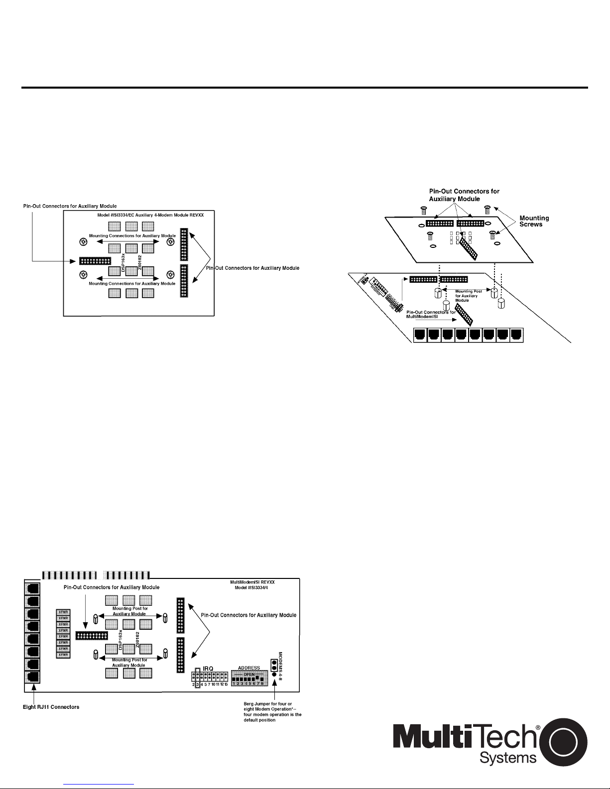
1. Carefully unpack the auxiliary module (Figure 1)
and the four mounting screws.
Figure 1. The ISI3334/EC Auxiliary Module
2. Make sure your computer (and any peripheral
equipment connected to it) is turned off. Failure to
do so may damage your ISI cards and your PC.
The ISI3334/EC can be installed in a PC-AT, 386,
486, or Pentium equivalent ISA or EISA bus
computer.
3. Remove the cover of your computer as instructed
in your computer’s documentation.
4. Locate the slot you will use for the auxiliary
module and remove the slot cover per the instructions in your computer’s documentation.
5. Change the Berg jumper to the eight modem
position on the ISI3334/4 (Figure 2 below). The
default position is four modem operation.
6. Referring to Figure 3 below, align the pin-out
connectors on the auxiliary module to the pin-out
connectors of the ISI3334/4. Mounting posts on
the ISI3334/4 should align with screw holes in the
auxiliary module.
Figure 3. Auxiliary Module Attachment
7. When properly aligned, attach the auxiliary
module to the ISI3334/4 and fasten the four
mounting screws.
8. Plug the ISI3334/4 into an available PC slot.
9. Drivers already installed in your PC automatically
recognize the additional four modems and allocate your system's resources appropriately.
See Chapter 3 of the
Installation Manual
MultiModemISI Hardware/Driver
for driver installation
82083000
May 4,1998
Figure 2. Berg Jumpers on the ISI3334/4
Page 2

 Loading...