

Page 1

FaxFinder IP
IP Fax Server
Model: FF240-IP
®
Administrator User Guide
Page 2

FaxFinder IP® Administrator User Guide
S000493A, Version A
Model: FF240-IP
Copyright © 2011, by Multi-Tech Systems, Inc.
This publication may not be reproduced, in whole or in part, without prior expressed written permission from
Multi-Tech Systems, Inc. All rights reserved.
Multi-Tech Systems, Inc. makes no representations or warranties with respect to the contents hereof and
specifically disclaims any implied warranties of merchantability or fitness for any particular purpose. Furthermore,
Multi-Tech Systems, Inc. reserves the right to revise this publication and to make changes from time to time in the
content hereof without obligation of Multi-Tech Systems, Inc. to notify any person or organization of such revisions
or changes. Check Multi-Tech’s web site for current versions of our product documentation.
Revisions
Level Date Description
A 06/08/11 Initial release.
Patents
This device covered by the following patents: 6,031,867; 6,012,113; 6,009,082; 5,905,794; 5,864,560; 5,815,567;
5,815,503; 5,812,534; 5,809,068; 5,790,532; 5,764,628; 5,764,627; 5,754,589; D394,250; 5,724,356; 5,673,268;
5,673,257; 5,644,594; 5,628,030; 5,619,508; 5,617,423; 5,600,649; 5,592,586; 5,577,041; 5,574,725; D374,222;
5,559,793; 5,546,448; 5,546,395; 5,535,204; 5,500,859; 5,471,470; 5,463,616; 5,453,986; 5,452,289; 5,450,425;
D361,764; D355,658; D355,653; D353,598; D353,144; 5,355,365; 5,309,562; 5,301,274, 6,219,708. Other patents
pending.
Trademarks
Multi-Tech Registered Trademarks: FF240-IP, Multi-Tech, and the Multi-Tech logo.
All other products and technologies are the trademarks or registered trademarks of their respective holders.
World Headquarters
Multi-Tech Systems, Inc.
2205 Woodale Drive, Mounds View, Minnesota 55112
Phone: 763-785-3500 or 800-328-9717 Fax: 763-785-9874
www.multitech.com
Contacting Multi-Tech Support
Online Support Portal: https://support.multitech.com
In order to better serve our customers, manage support requests and shorten resolution times, we have created
the online web portal allowing you to submit questions regarding Multi-Tech products directly to our technical
support team. Get answers to your most complex questions, ranging from implementation, troubleshooting,
product configuration, firmware upgrades and much more.
To create an account and submit a Support Case on the Portal, visit support.multitech.com.
Knowledge Base and Support Services: www.multitech.com/support.go
The Knowledge Base provides immediate answers to your questions and gives you access to support resolutions
for all Multi-Tech products. Visit our support area on the website for other support services.
Technical Support
Country By Email By Phone
Europe, Middle East, Africa: support@multitech.co.uk (44) 118 959 7774
U.S., Canada, all others: support@multitech.com (800) 972-2439 or (763) 717-5863
Warranty
Warranty information can be found at: http://www.multitech.com/warranty.go
Page 3

CONTENTS
CHAPTER 1 – PRODUCT DESCRIPTION & SPECIFICATIONS ..................................................................... 5
P
RODUCT DESCRIPTION .................................................................................................................................. 5
AFETY WARNINGS ........................................................................................................................................ 5
S
T
ECHNICAL SPECIFICATIONS ............................................................................................................................. 6
CHAPTER 2 – GETTING STARTED ........................................................................................................... 7
FF240-IP
M
XTERNAL DESCRIPTIONS .............................................................................................................................. 11
E
I
NSTALLATION OVERVIEW .............................................................................................................................. 12
CHAPTER 3 – WEB MANAGEMENT INTERFACE ................................................................................... 18
L
OGIN SCREEN .............................................................................................................................. ............... 18
H
OME SCREEN ............................................................................................................................................ 19
S
TATUS & LOGS SECTION .............................................................................................................................. 20
YSTEM CONFIGURATION SECTION ................................................................................................................. 29
S
AX CONFIGURATION SECTION ....................................................................................................................... 41
F
SERS SECTION ........................................................................................................................................... 56
U
C
ONTACTS SECTION .............................................................................................................................. ........ 60
OPERATING MODES......................................................................................................................... 7
ECHANICAL MOUNTING ............................................................................................................................. 10
Back Panel Connections ........................................................................................................ ............... 11
Front Panel
LEDs .................................................................................................................................. 11
Forgot Password? ................................................................................................................................ 18
System Statu
s....................................................................................................................................... 20
Fax Status ............................................................................................................................................. 21
Mail Queue .......................................................................................................................................... 24
Mail Log ............................................................................................................................................... 25
Inbound Fax Log ................................................................................................................................... 26
Outbound Fax Log ................................................................................................................................ 27
Call Log ................................................................................................................................................. 28
Network ............................................................................................................................................... 29
SMTP .......................................................................................................................... .......................... 30
Time ..................................................................................................................................................... 31
Printer .................................................................................................................................................. 32
Shares .................................................................................................................................................. 34
Certificates .................................................................................................................. ......................... 36
Save/Restore
Software Up
........................................................................................................................................ 38
date .................................................................................................................................. 39
Reboot ................................................................................................................................................. 40
Debug ......................................................................................................................... .......................... 40
SIP / T.38 Configuration
....................................................................................................................... 41
Inbound Routing .................................................................................................................................. 44
Outbound ............................................................................................................................................. 48
Outbound Approval ............................................................................................................................. 49
Cover Pages ......................................................................................................................................... 51
Store & Forward Fax (T
.37) .................................................................................................................. 53
Fax Log ................................................................................................................................................. 55
Personal ............................................................................................................................................... 60
Global ................................................................................................................................................... 61
Personal Groups ................................................................................................................................... 62
Multi-Tech Systems, Inc. FF240-IP Admin User Guide 3
Page 4

Global Groups ...................................................................................................................................... 62
S
END A FAX SCREEN ..................................................................................................................................... 63
Send Fax ............................................................................................................................................... 64
OGOUT ..................................................................................................................................................... 66
L
CHAPTER 4 – CLIENT SOFTWARE INSTALLATION ................................................................................. 67
I
NSTALLATION ............................................................................................................................................. 67
Push Installation Me
S
ETTING THE USAGE RIGHTS FOR THE PRINTER ................................................................................................. 72
SSOCIATING CLIENT SOFTWARE AND USER WITH THE FF240-IP UNIT ................................................................. 72
A
Disassociating the Client from a Specifi
thod .................................................................................................................... 71
c FF240-IP Unit ...................................................................... 75
CHAPTER 5 – FAXFINDER-IP OPERATION ............................................................................................ 76
S
ENDING FAXES ........................................................................................................................................... 77
The Schedule Fax Screen (New Fax) .................................................................................................... 77
Send Fax with Clien
t Software ............................................................................................................. 81
Send Fax by Printing ............................................................................................................................ 81
Send Fax from Email (T.37) .................................................................................................................. 82
Send Fax from Web Interface .............................................................................................................. 82
Send Fax by Web
SING THE CLIENT SOFTWARE........................................................................................................................ 83
U
File Menu Command Descriptions
Edit Menu Command Descriptions
Tools Menu Command Des
Devices Tab (Main W
Print Capture Tab (Main W
U
SING THE MULTI-TECH TIFF VIEWER ............................................................................................................. 90
Toolbar Icons
Importing Fax Images into Other A
API ........................................................................................................................... 83
...................................................................................................... 83
...................................................................................................... 84
criptions.................................................................................................... 86
indow) ................................................................................................................ 87
indow) ....................................................................................................... 89
....................................................................................................................................... 90
pplication Programs ..................................................................... 91
APPENDIX A – TROUBLESHOOTING .................................................................................................... 92
APPENDIX B – CUSTOMIZATION ......................................................................................................... 95
W
EB SERVICES API ...................................................................................................................................... 95
T.37
ADVANCED USAGE ............................................................................................................................. 116
APPENDIX C – CREATING COVER PAGES ........................................................................................... 118
S
OME OF THE SOFTWARE KNOWN TO WORK .................................................................................................. 118
T
EXT FIELD NAMES AND DESCRIPTIONS ......................................................................................................... 118
APPENDIX E – REGULATORY COMPLIANCE ....................................................................................... 119
APPENDIX F - ENVIRONMENTAL INFORMATION ............................................................................... 121
APPENDIX G – END USER LICENSE AGREEMENT ................................................................................ 124
IMPORTANT
– READ BEFORE OPERATING ............................................................................................. 124
INDEX .............................................................................................................................................. 126
Multi-Tech Systems, Inc. FF240-IP Admin User Guide 4
Page 5
Chapter 1 – Product Description &
Specifications
Product Description
The FaxFinder IP provides fax functionality to an IP-based telephony environment, eliminating the need
for analog-based phone connections dedicated to supporting analog fax applications.
We Supply
FF240-IP
• A FF240-IP with factory-installed software
• One power supply with power cord
• A product CD that contains: a software package
for client PCs and additional documentation
• A serial console cable
Safety Warnings
Internal Lithium Battery
• A lithium battery located within product provides backup power for the timekeeping
capability. The battery has an estimated life expectancy of ten years.
• When the battery starts to weaken, the date and time may be incorrect. If the battery fails,
the board must be sent back to Multi-Tech Systems for battery replacement.
• Lithium cells and batteries are subject to the Provisions for International Transportation.
Multi-Tech Systems, Inc. confirms that the Lithium batteries used in the Multi-Tech product(s)
referenced in this manual comply with Special Provision 188 of the UN Model Regulations,
Special Provision A45 of the ICAO-TI/IATA-DGR (Air), Special Provision 310 of the IMDG
Code, and Special Provision 188 of the ADR and RID (Road and Rail Europe).
Warning! There is danger of explosion if the battery is incorrectly replaced!
Ethernet Ports Caution
Caution: The Ethernet ports and command ports are not designed to be connected to a Public
Telecommunication Network.
Multi-Tech Systems, Inc. FF240-IP Admin User Guide 5
Page 6

Technical Specifications
Chapter 1: Product Description and Specifications
Connectors
1 RJ45 Console Serial Port, 1 RJ45 Ethernet Port,
2 USB Ports (inactive)
FF240-IP
Size 9.1” W x 6.1” L x 1.7” H (23.11 cm x 15.49 cm x 4.32 cm)
Weight 2.6 lbs. (1.2 kg)
Input Voltage Requirements 12 V @ 5A
12 v Typical: 0.870 A / 10.65 W;
Maximum Power Consumption*
Max: 0.955 A / 11.65 W
Peak Reset:
Inrush Current: 15.40 AMPS
Operating Environment
-22° to 140° F (-30° to +60° C) – [UL listed @ 104° F/ 40° C]
relative humidity 20 to 90% noncondensing
Storage Temperature -40° to 185° F (-40° to +85° C)
EMC Approvals FCC Part 15 Class A, EN 55022 Class A, EN 55024
Safety Approvals UL\cUL 60950-1 ed.2, IEC 60950-1 ed.2 & EN (2006 +am.11)
Maximum T.38 Ports 8
Web Connections 50
File Upload Size** 50MB is the maximum with:
48MB max for the Send Fax Web page
36MB max for T.37, Client software and API
Warranty 2 years
* Multi-Tech Systems, Inc. recommends that the customer incorporate a 10% buffer into their power source when
determining product load.
** The difference in maximum size allowed is due to the data encoding for T.37, the client software and API
attachments.
Multi-Tech Systems, Inc. FF240-IP Admin User Guide 6
Page 7
Chapter 2 – Getting Started
Introduction
This chapter shows example usage scenarios for inbound and outbound faxes as well as basic setup
instructions for your Multi-Tech Model FF240-IP. The setup process includes both cabling of the FF240-IP
unit and configuration of the FF240-IP server software. The FF240-IP server software resides on the
FF240-IP unit and does not need to be installed.
FF240-IP Operating Modes
When placed in the optimal environment, the Multi-Tech Systems FF240-IP can provide a host of useful
functions. Inbound routing, that is fax transmissions coming into the FF240-IP unit, can be sent to many
destinations, as shown below. Following that, there are some outbound fax examples showing different
ways that faxes can be sent by users.
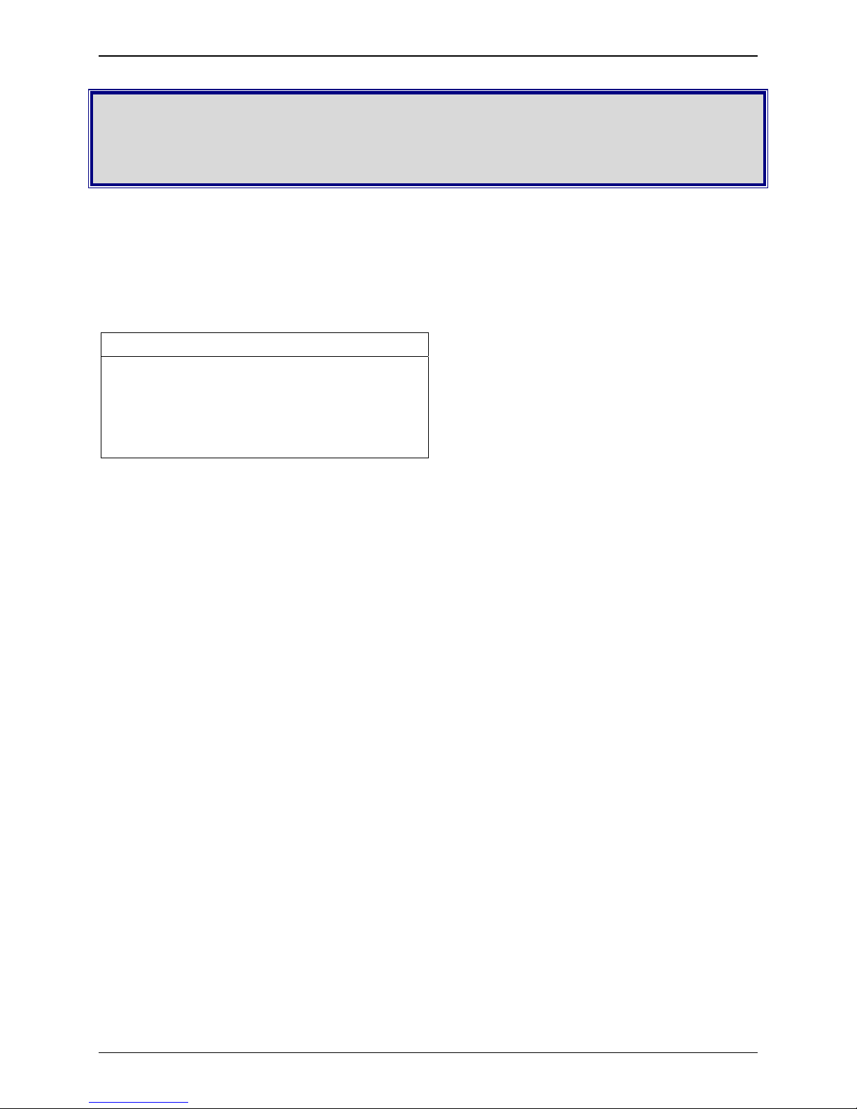
Inbound Routing. Fax users receive faxes in the form of email attachments. Also, inbound faxes can be
automatically printed or stored in a shared folder for archiving or multiple user access.
The red arrows indicate an incoming fax; the green arrows show all the possible routing options and the
blue arrows show the incoming fax converted to an email.
Just like a telephone, the FF240-IP has phone numbers mapped to it. So a call from the analog fax
machine is routed to the FF240-IP just as any other call is routed. Once the fax is received on the FF240IP, it will use its inbound routing settings to send the fax to a printer, network share, email client or any
combination of these.
Multi-Tech Systems, Inc. FF240-IP Admin User Guide 7
Page 8
Chapter 2: Getting Started
Outbound Routing. FaxFinder users on the network can send faxes directly from their Windows PC using
any application program that can print (if the Client software is installed). The application program must
be set so that the FF240-IP itself is its printing destination. In response to the ‘Print’ command, the
FF240-IP turns the ‘print file’ image into a fax. Store and Forward faxing (T.37) allows for emails to be
sent through the FF240-IP as a fax or users can simply log in to the web interface (Send Fax screen) and
send a fax from the unit directly. Graphic depictions of these outbound routing examples are shown
below.
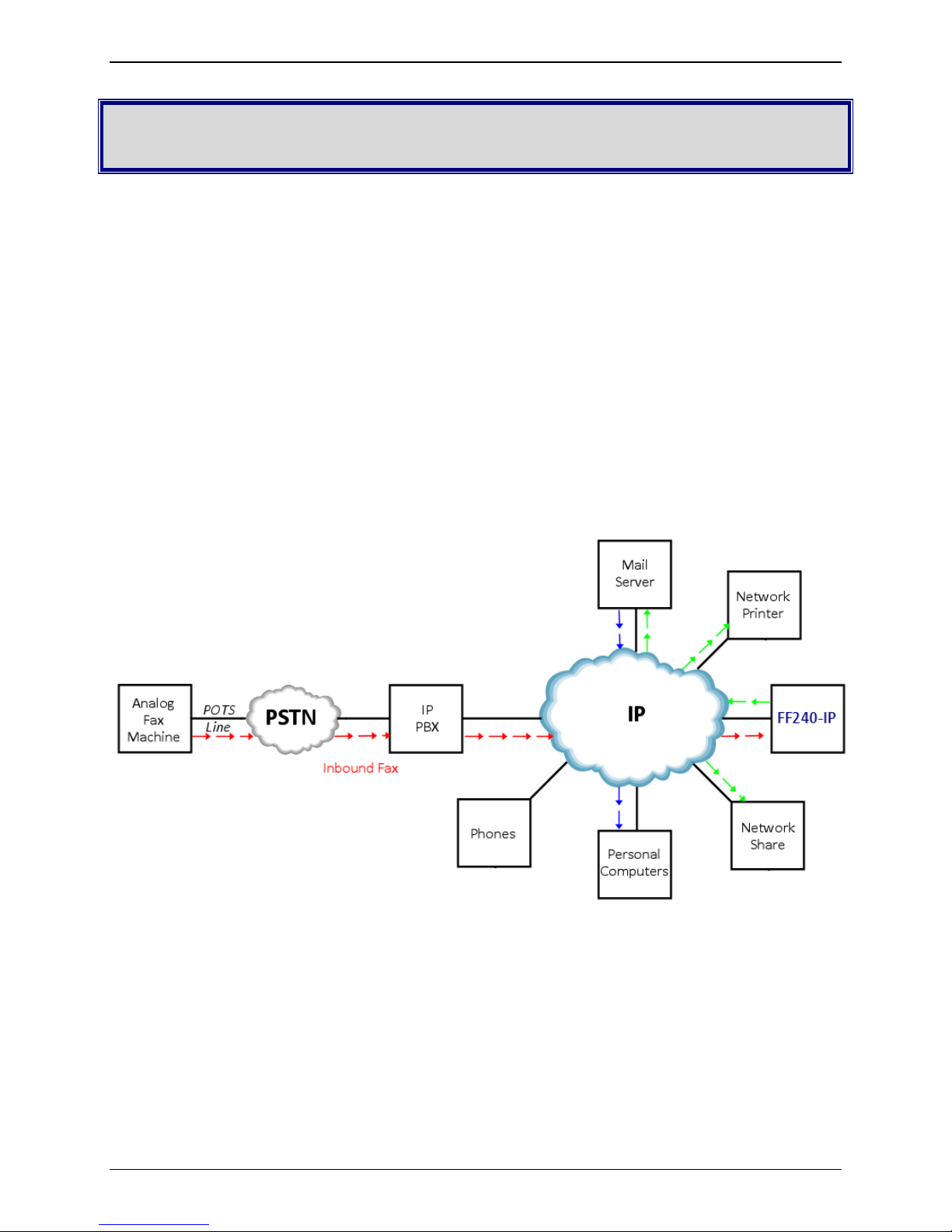
T.37
In this example, the FF240-IP acts as a mail server. The red arrows show an email originating from a PC
and the green arrows show the FF240-IP sending that email to a phone number.
Send Fax screen
Here the red arrows indicate a user browsing to the FF240-IP and utilizing the Send Fax page. The green
arrows represent the FF240-IP sending that fax to a phone number.
Multi-Tech Systems, Inc. FF240-IP Admin User Guide 8
Page 9
Chapter 2: Getting Started
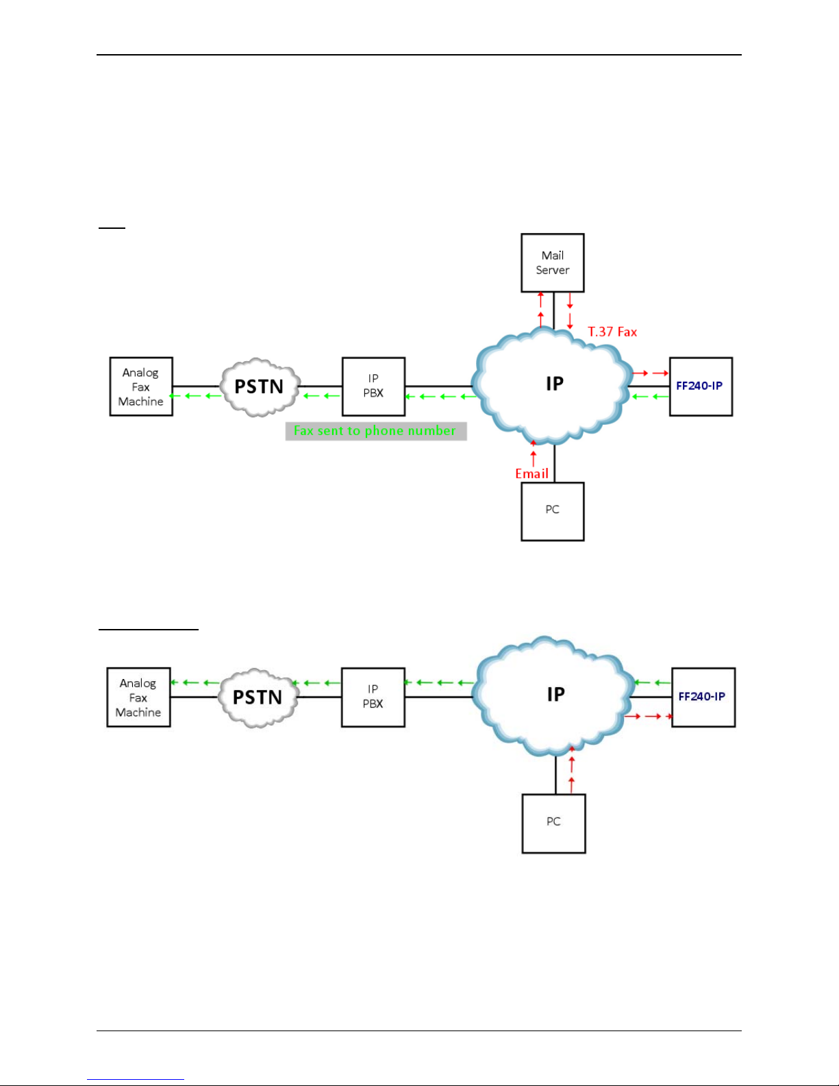
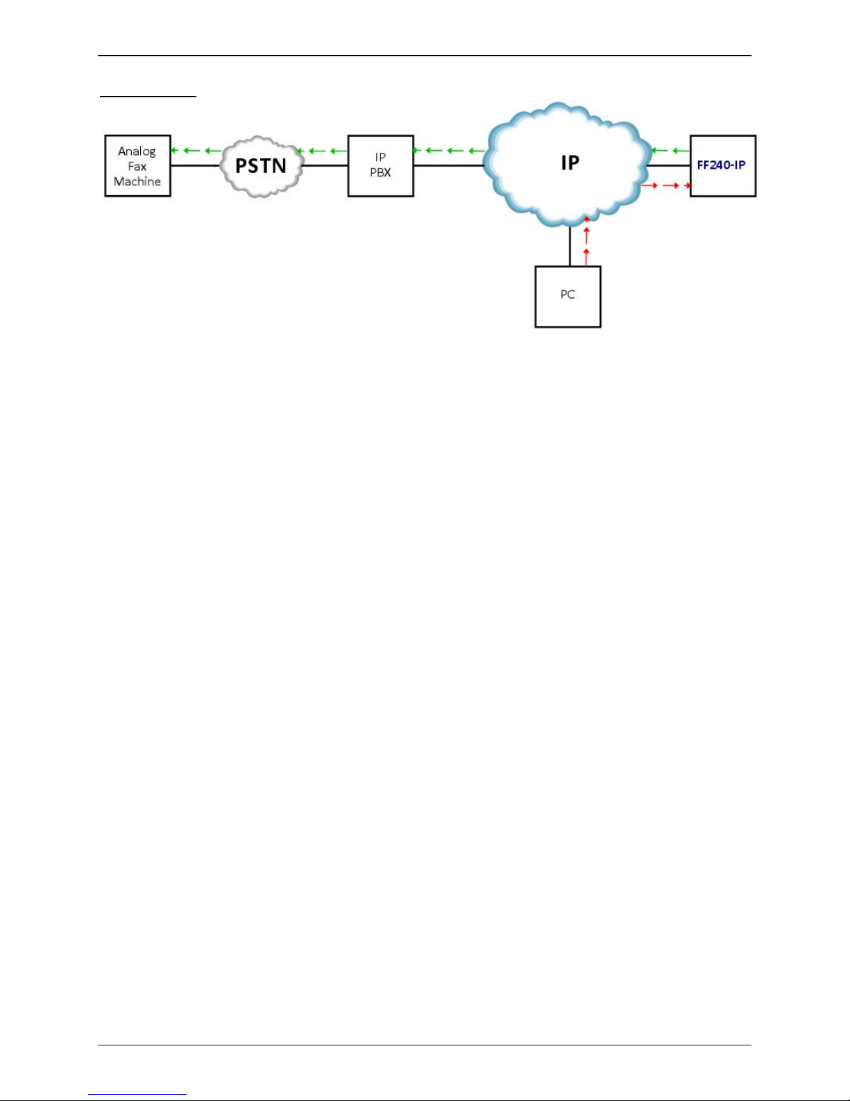
Client software
Here the red arrows show the use of the Client software and the green arrows represent the FF240-IP
sending that fax to a phone number.
This example requires that the FaxFinder Client software be installed on a user’s Windows PC.
The Client software can be used in two ways:
1) Invoke it directly to send faxes.
2) Invoke it indirectly using the Print function from any application program that can print (e.g.
Microsoft Word) with the FaxFinder installed as an available printer.
Multi-Tech Systems, Inc. FF240-IP Admin User Guide 9
Page 10

Chapter 2: Getting Started
Mechanical Mounting
Rack Mounting
Ensure proper installation of the unit in a closed or multi-unit enclosure by following the
recommended installation as defined by the enclosure manufacturer. Do not place the unit directly
on top of other equipment or place other equipment directly on top of the unit. If installing the unit
in a closed or multi-unit enclosure, ensure adequate airflow within the rack so that the maximum
recommended ambient temperature (40° C) is not exceeded. Ensure that the unit is properly
connected to earth ground by verifying that it is reliably grounded when mounted within a rack. If a
power strip is used, ensure that the power strip provides adequate grounding of the attached
apparatus.
When mounting the equipment in the rack, make sure mechanical loading is even to avoid a
hazardous condition. The rack used should safely support the combined weight of all the
equipment it supports.
Ensure that the mains supply circuit is capable of handling the load of the equipment. See the
power label on the equipment for load requirements.
This equipment should only be installed by properly qualified service personnel. Only connect like
circuits - connect SELV (Secondary Extra Low Voltage) circuits to SELV circuits and TN
(Telecommunications Network) circuits to TN circuits.
Note:
The ambient temperature of the rack interior must not exceed 40° Celsius.
19-Inch Rack Enclosure Mounting Procedure
Attaching the FF240-IP to the rail of an EIA 19-inch rack enclosure will likely require two persons.
Essentially, the technicians must attach the brackets to the FF240-IP chassis with the screws
provided and then secure unit to rack rails by the brackets. Because equipment racks vary, screws
for rack-rail mounting are not provided. Follow the instructions of the rack manufacturer and use
screws that fit.
1. Remove the side screws of the unit.
2. Position the rack-mounting brackets on the FF240-IP using the screw holes.
3. Secure the brackets to the FF240-IP using the screws that were removed.
4. Mount the FF240-IP in the rack enclosure per the rack manufacturer’s mounting procedure.
Multi-Tech Systems, Inc. FF240-IP Admin User Guide 10
Page 11
External Descriptions
Back Panel Connections
Descriptions of the connections available on the back of the FF240-IP unit.
Power Connector: Threaded connector for the provided power supply.
Console: RJ 45 connection for serial access and control of the FF240-IP units.
USB Ports (reserved for future use): These ports are inactive.
Reset: Pressing the reset button will reboot the unit.
LAN 1: RJ 45 receptacle for network connection.
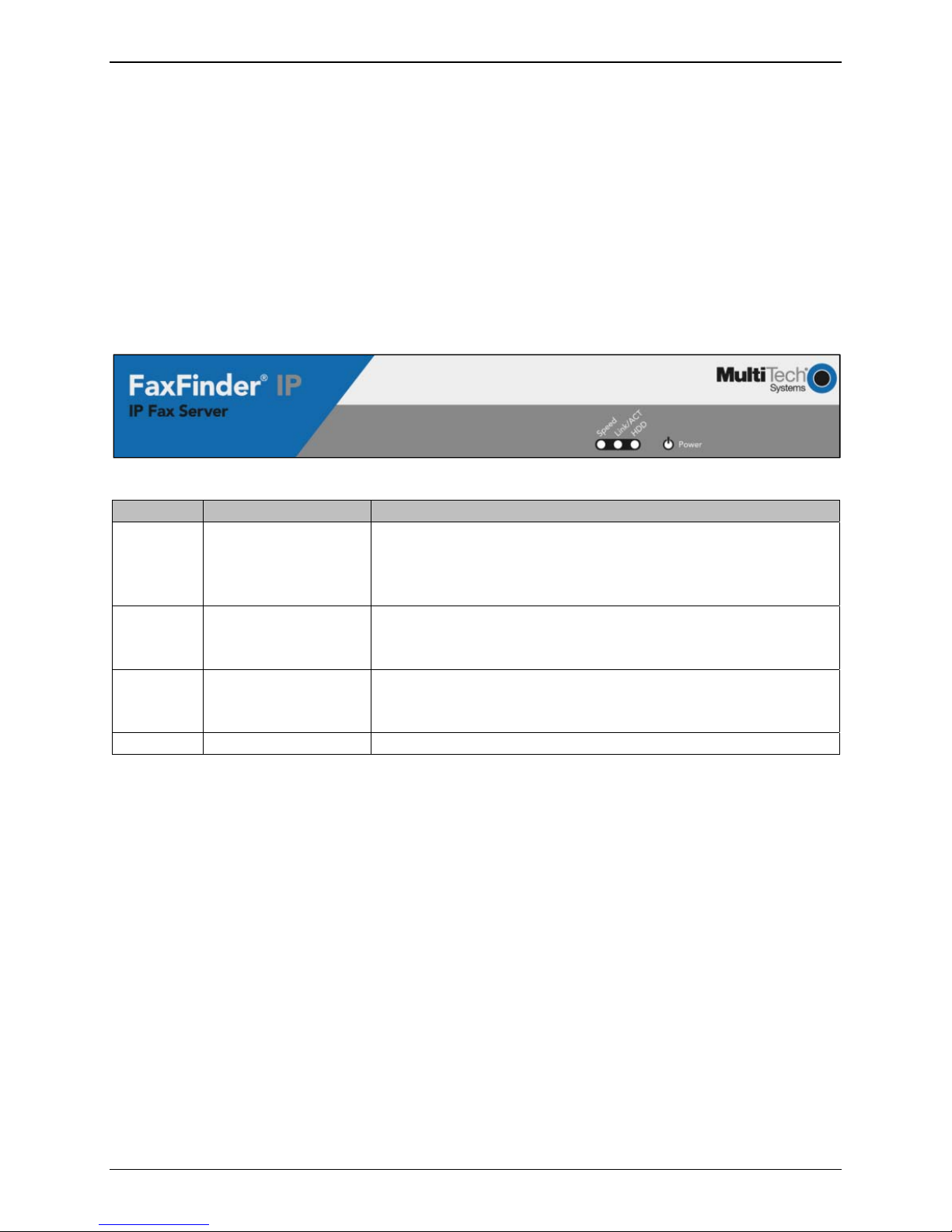
Front Panel LEDs
Chapter 2: Getting Started
Label Name Description
Speed Speed When lit, if the color is:
Green: Ethernet rate is 1000 Mbps;
Yellow: Ethernet rate is 100 Mbps
Unlit: Ethernet rate is 10 Mbps
Link/Act Link / Activity Lit when a physical link has been established with the Ethernet
network.
Blinking when there is activity.
HDD Hard Disk Drive When the internal hard drive is accessed, this LED will light
yellow.
When unlit, HDD is not being accessed.
Power Power Solid (constant) green if unit is on.
Multi-Tech Systems, Inc. FF240-IP Admin User Guide 11
Page 12

Chapter 2: Getting Started
Installation Overview
Part A: Cabling – Connecting the FF240-IP to Power and Ethernet
Summary: Place the FF240-IP in a convenient location, and then connect the power supply to your AC
power outlet and then connect to the Ethernet network.
1. Connect FF240-IP to AC Outlet.
Plug the DC
Receptacle on your FF240-IP.
Caution: Use only the DC power transformer supplied with the FF240-IP. Use of any other transformer
2. Verify Powering.
After power
power transformer into a power outlet or power strip. Secure the other end to the Power
voids the warranty and can damage the FF240-IP.
is applied, the Power LED comes on immediately.
3. Connect FF240-IP to Ethernet
Plug one end of your RJ45 Ethernet cable into the FF240-IP’s Ethernet jack and the other end into your
network. This Ethernet cable is not included with your FF240-IP unit.
Caution: Before connecting to the Ethernet Network, make sure that the network to which you are
connecting the FF240-IP is not a 192.168.2.x subnet. Because the FF240-IP’s factory default IP
address is 192.168.2.1, connecting it to a network that has a different device at that same IP
address would cause data interference.
If it is a 192.168.2.x subnet, connect from the Administrative PC to the FF240-IP using an RJ 45
crossover cable until the FF240-IP’s IP address has been configured. Thereafter, connect the
FF240-IP into the network with an ordinary RJ 45 cable.
Network.
Multi-Tech Systems, Inc. FF240-IP Admin User Guide 12
Page 13

Chapter 2: Getting Started
Part B: Configuring the FF240-IP Server
1. Setting Admin PC to Startup IP Address
To initially access the FF240-IP, you will need to connect the unit directly to a compatible computer.
This process is detailed below. After the first setup, you can change the IP address of the FF240-IP
unit to one that is capable of operating on the network where it will permanently reside. If the FF240IP is already attached to a network, the Client software can Auto-discover the IP address.
Alternatively, using the Command/Console port, you can use a terminal program (like HyperTerminal)
and type “ifconfig eth0 ‘IP address’”. After that you can temporarily use the web interface for access
and permanently set the IP address in the System Configuration section.
A. Connect a PC directly to your FF240-IP unit using an RJ 45 network cable (this may entail
disconnecting the PC from its current network).
B. Set the computer now connected to the FF240-IP to IP address http://192.168.2.x, where x can
be from 2 to 254 (the factory default for the FF240-IP is 192.168.2.1). Make sure you write down
your PC’s original network settings so you may re-enter them when finished.
Windows XP/2003
a. From the Windows desktop, right-click on
“My Network Places,” and select
“Properties.”
b. In the Network Connection screen, right-
click on “Local Area Connection.”
c. In the Local Area Connection Properties
screen, on the “General” tab, scroll to the
“Internet Protocol (TCP/IP)” entry and
select it. Click “Properties.”
d. In the Internet Protocol (TCP/IP)
Properties screen, record the existing IP
address. Then reset the IP address to
192.168.2.2.
Windows 2000
a. From the Windows desktop, right-click on
“My Network Places,” and select
“Properties.”
b. In the Network and Dialup Connections
screen, right-click on “Local Area
Connection” and select “Properties.”
c. In the Local Area Connection Properties
screen, select the “Internet Protocol
(TCP/IP)” entry. Click “Properties.”
d. In the Internet Protocol (TCP/IP)
Properties screen, record the existing IP
address. Then reset the IP address to
192.168.2.2.
Windows Vista
a. Click on Start and go to Network.
b. In the left-hand ‘Folders’ pane, Right-click on Network and select Properties.
c. For the Local Area Connection, click on the View Status link.
d. In the Status window, click on Properties. Click Continue when the permission window pops-
up.
e. In the Properties window, click once to highlight “Internet Protocol Version 4 (TCP/IPv4)” and
then click Properties below.
f. Here you can select the “Use the following IP address:” radio button, and then set the “IP
Address” to 192.168.2.2.
g. Click OK, then click Close and then Close again.
Multi-Tech Systems, Inc. FF240-IP Admin User Guide 13
Page 14

Chapter 2: Getting Started
2. Logging In
A. Bring up a Web browser on your PC. In the browser address line, type the IP address of the
FF240-IP: type 192.168.2.1 and press Enter.
Note
: Your browser may show a warning message at this point. This is related to the certificate
issued by the FF240-IP. Browsers will not allow access without a valid certificate - the FF240-IP
does have a valid certificate, but it is self-signed (i.e. no third party verification), so your browser
displays a warning about this. You may safely continue (more details are given in step 5).
B. The Login screen will appear. At this point you can be assured that the FF240-IP is connected to
the network.
C. At the Login screen, enter admin (all lower case) in the Username field and admin (all lower case)
in the Password field.
D. Click the Login button. The Web Management Home screen will appear. From this screen, you
can access all of the FF240-IP Server software screens.
Note
: The FF240-IP units have real-time clocks. The default setting is to set the time via a timer
server (time.nist.gov). If the time is not accurate, a message may be issued by the web browser
that the certificate is invalid or expired. If this occurs, you should add an exception temporarily
until the IP Address and date/time are correctly set.
Once the date/time and IP Address are set, you will be able to generate a certificate with your
information (see Certificates section of Chapter 3).
3. Setting FF240-IP IP Addresses
A. Click on Sy
stem Configuration in the top navigation bar.
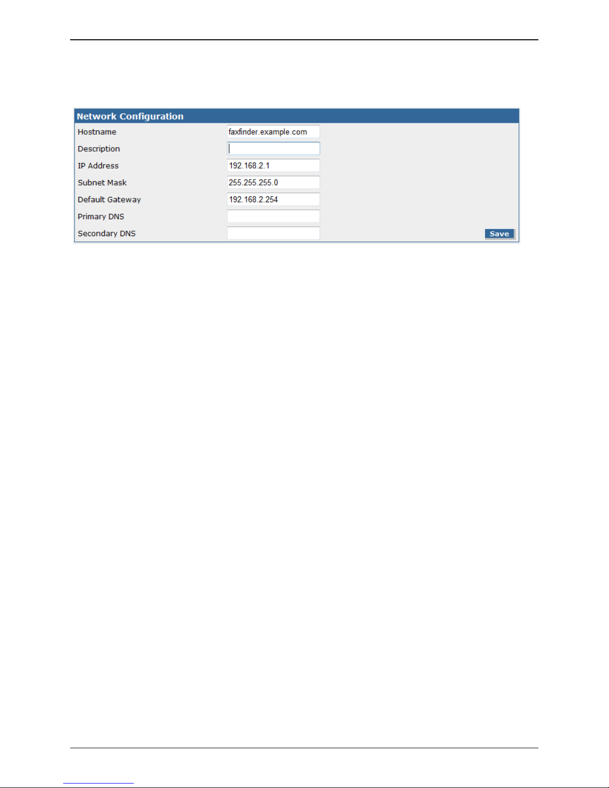
B. Network Configuration is the first sub-category found in the left-hand navigation frame. Fill in the
IP information that applies to your unit. The fields for “IP Address,” “Subnet Mask,” and “Default
Gateway” are required.
The Hostname contains the domain name for the FF240-IP. This is used
for T.37 store and forward faxing. Email clients must send the email with the ‘To’ address in the
format: FAX=7635551234@Hostname (where “Hostname” is the FF240-IP domain name). A
“Primary DNS” and “Secondary DNS” may be considered optional, but, in any case, do not leave
an invalid value in either of these fields.
C. Click Save. After the Save button has been clicked, it takes a moment for the FF240-IP to update
the addresses.
4. Resetting Admin PC to Its Regular IP Address
p #1 above, you recorded the original network configuration of the administrator’s PC and then
In ste
reset the IP address as required to allow communication with the FF240-IP unit. You may now set the
network settings of the administrator’s PC back to its original value or to any other value that will
allow you to communicate with the FF240-IP at its new IP address.
Multi-Tech Systems, Inc. FF240-IP Admin User Guide 14
Page 15
Chapter 2: Getting Started
5. Log In After Reset
Having reset the IP address of the administrator’s PC, you must log into the FF240-IP Server software
again. Enter the new IP address of the FF240-IP into your browser, and then enter admin as Username
and admin as Password to log in again.
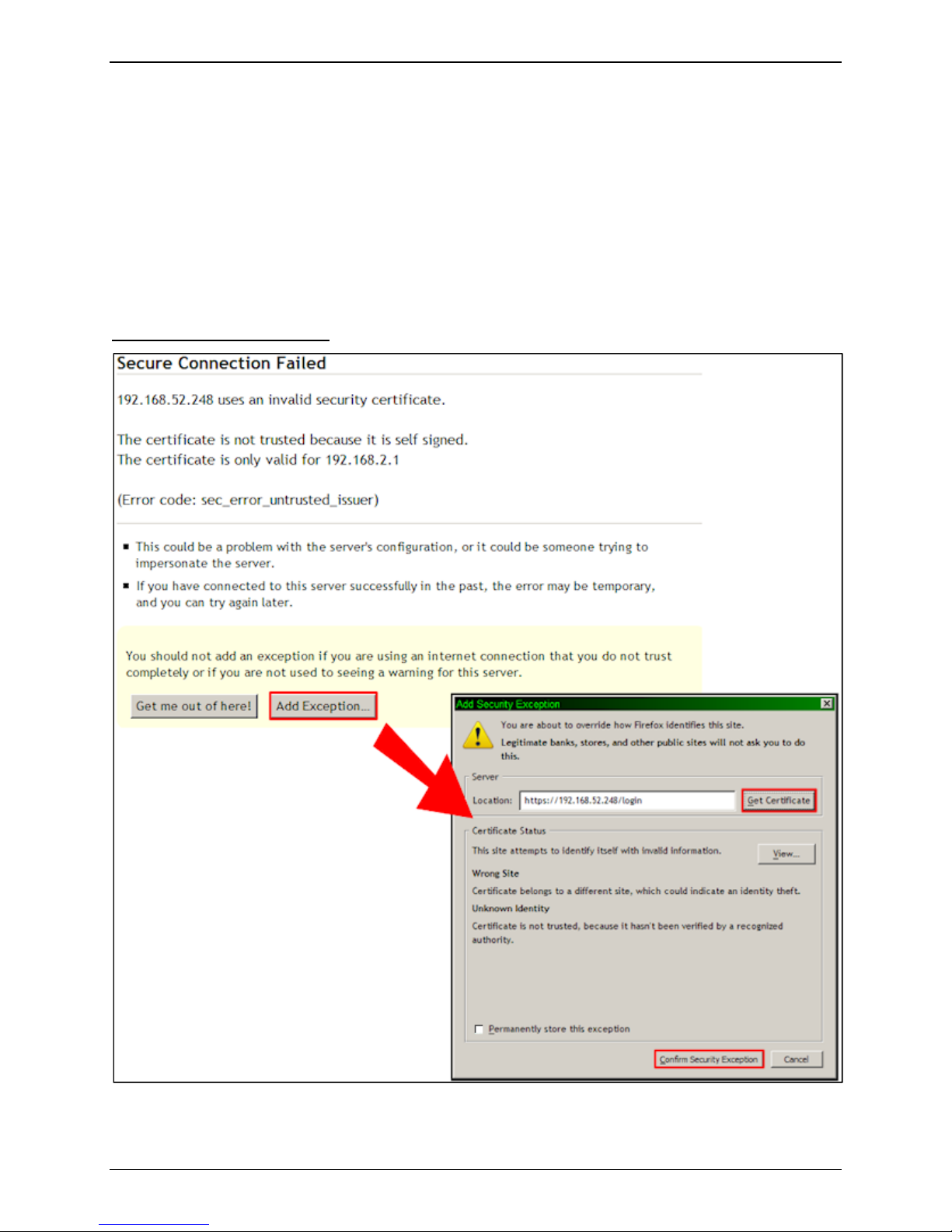
If the IP has been changed, your browser may show a warning message at this point. This is related to
the certificate issued by the FF240-IP (the default is for the IP address 192.168.2.1 – changing the IP
will cause an invalid certificate warning). Browsers will not allow access without a valid certificate
and the FF240-IP does have a valid certificate, but it is self-signed (i.e. no third party verification), so
your browser displays a warning about this. You may safely continue (Internet Explorer), or in the
case of Firefox, temporarily add the FF240-IP certificate to the exception list.
Firefox Add Exception Process:
Multi-Tech Systems, Inc. FF240-IP Admin User Guide 15
Page 16

Chapter 2: Getting Started
6. Save your Configuration to a File on the Local PC
Now that you have setup the FF240-IP unit to the necessary configuration, it is a good idea to save the
parameters in case the unit needs to be restored after a factory default. This will save you time if you
want to test different settings or need to do some troubleshooting as you will be able to return to
these settings easily. Click on the System Configuration top navigation link and then click on the
Save/Restore link in the left-hand pane. In the Save/Restore Configuration window, click on the Save
Config link in the upper right hand corner to save what you have set so far. The file name
“config_nnnn.bin” (with the n’s replaced by the version number and current date) will appear in the
dialog for where you can store the file. This config file can then be used to restore the FF240-IP to this
configuration.
7. Sending Test Faxes
up an email address for the Administrator by going to the Users section (top navigation bar) and
Set
click on the Edit action item for the Administrator account to add an email address. Next go to the Fax
Configuration | Inbound Routing page and verify where the fax will be routed – if no settings are
changed, any incoming fax will be emailed to the Administrator email address (by default, all incoming
faxes are routed to the Administrator). Next set the SMTP parameters in the SMTP Configuration
section of the System Configuration.
A two step approach is recommended to verify faxing is working properly using FF240-IP. In the first
step, the FF240-IP sends a fax to itself to verify that the fax is sent/received and routed properly. If
this works properly, the next step is to configure the SIP/T.38 settings on FF240-IP to match your
SIP/T.38 network requirements and send test faxes again.
Sending a loop-back test fax:
A. Go to the Fax Configuration screen, enter the IP Address of your FF240-IP in the SIP
Proxy/Gateway field leaving default values in the other fields, and click Save to accept the
changes. This will cause all outbound faxes to be looped-back to FF240-IP. Next, go the Send Fax
screen, select "Enter Recipient Info" in the Find Recipient field, and enter the phone number 123456-7890 in the "Fax Number" field under Recipient Information. Enter some text in the Subject
and Comments fields under Cover Page Information, and then click the "Send Fax" button at the
bottom of the screen to send the fax.
B. Click on the Status & Logs link in the top navigation bar, and then click on the Fax Status link to
observe the status of the loop-back fax. You should see "sending" on one of the channels, and
"receiving" on another. When the fax completes, click on the Inbound Fax Log link in the lefthand frame to see if the FF240-IP sends the email. If the email was sent successfully, the
“Inbound Fax Log” field will contain the message. Click on the Details link to see where it was
delivered. If the email is not delivered within 5 minutes, see the “Troubleshooting Appendix;”
specifically “What if I don’t get the email to me of the test fax that I sent?”
Multi-Tech Systems, Inc. FF240-IP Admin User Guide 16
Page 17

Chapter 2: Getting Started
Sending a test fax on your SIP network:
A. Go to the Fax Configuration page and configure SIP Proxy/Gateway field with the IP address of
the SIP device the FF240-IP will communicate with when sending faxes. This could be a SIP proxy,
SIP Gateway or IP PBX. Enter the SIP Domain if required by your SIP device. If your SIP Device
requires authorization, enable the Authorization Required check box, and fill out the Username,
Password, Confirm Password fields as required. Enable Use Registrar and enter the Registrar IP
address if the FF240-IP must use a registrar for SIP call routing. Configure the Local, SIP Proxy,
and Registrar Port values if your SIP device requires something other than the normal default
5060 value. Configure the T.38 values as required by your SIP device, the default values are a
good starting point for most installations. You may need to reconfigure the Fax Method to T.30
Pass Through if your SIP device does not support T.38. You may configure FF240-IP to use some
or all of the extension digits passed to it by the SIP device for routing the incoming faxes by
modifying the Extension Digits and Extension Length fields. When you finish configuring SIP/T.38
values, click the Save button. Go to the Send Fax screen and send a fax to a remote fax machine
accessible through your SIP device. Configure the dial plan on your SIP device to properly route
incoming fax calls to FF240-IP, and then send a fax to FF240-IP from a remote fax machine.
B. View the status of the fax by viewing Fax Status and Inbound/Outbound Fax Log screens under
Status and Logs similar to what was done for the loop-back fax above.
C. Verify also that you can open the fax in a PDF viewer program on your computer. The PDF viewer
could be any commercial or open source PDF viewer. You can also choose to have your fax
messages delivered as TIFF files. The TIFF viewer program you use could be either the Multi-Tech
TIFF Viewer or a graphic file viewer included with or installed in your PC. (The Multi-Tech TIFF
viewer is included on the Product CD and installed with other client programs. During
installation, you can choose to associate all TIFF files with the Multi-Tech TIFF Viewer or leave
them associated with another program.) In your email program, double-click on the file attached
to the email message. The PDF or TIFF viewer program will come up automatically displaying the
fax file.
8. Adding Client-Users
It is important to
get the users added for the FF240-IP as the contact database is tied to the user
account for those users who will send faxes. The best case scenario would have all potential users
added before the users install the client software and begin to use the FF240-IP, that way, the contact
lists will be automatically populated with any contacts they already have that have been entered into
the FF240-IP unit for that user.
A. Click on the Users link in the top navigation bar to create entries for the other users in your office
who will send faxes through the FF240-IP. For each such FF240-IP client/user, enter the
Username, Password, phone numbers and email address in the appropriate fields.
B. Click on the Add
link in the upper right-hand corner of the Users window to create a new client
user. Ensure that you click on the Update button after each entry before creating the next one.
The new User will appear in the list of FaxFinder Users.
An alternative method for populating the User database is Comma Separated Value importation.
By default, there is an Administrator user that cannot be deleted, but you can click on the Edit
Note:
action item to change the information and password.
Multi-Tech Systems, Inc. FF240-IP Admin User Guide 17
Page 18
Chapter 3 – Web Management
Interface
Introduction
In this chapter, we present the screens of the FF240-IP web management interface and describe the
sub-categories for each screen. The major sections are presented along the top navigation bar of the
web interface and most of these will activate a left-hand navigation window of sub-categories when
clicked. As with any secure browser-based user interface, a certificate is required to allow access. The
certificate used by the FF240-IP unit is self-signed, meaning that you will see a security warning when
you first access the unit from a browser. These warnings do not mean that the unit is not secure; it is
merely an indication that the validated certificate is not signed by a third party. Please select the option
to continue when you are presented this information.
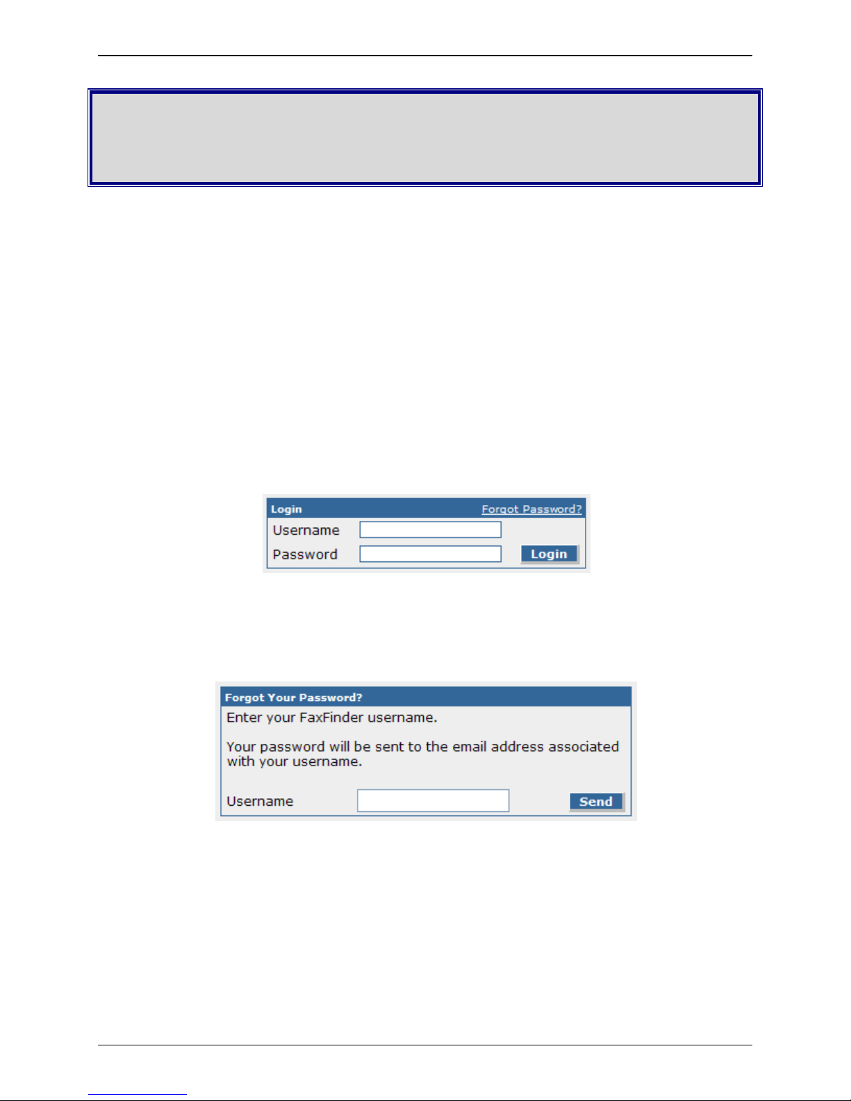
Login Screen
When you enter the IP address of your FF240-IP unit in a browser, you will first see the certificate
warning as noted above. After continuing past the warning, you will be presented with the Login Screen.
When you first receive your unit, the default username is admin and the default password is admin.
Forgot Password?
Should you forget your password, a link is provided that you can click to have your password emailed to
you for access. Enter your username in the form provided and click the Send button to have the FF240IP email the password.
Multi-Tech Systems, Inc. FF240-IP Admin User Guide 18
Page 19
Chapter 3: Web Management Interface
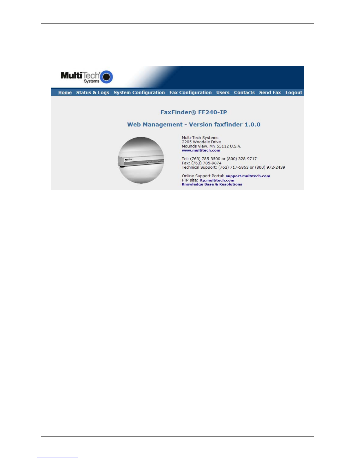
Home Screen
The FF240-IP Home screen displays the model name, software version and contact resources.
Multi-Tech Systems, Inc. FF240-IP Admin User Guide 19
Page 20
Chapter 3: Web Management Interface
Status & Logs Section
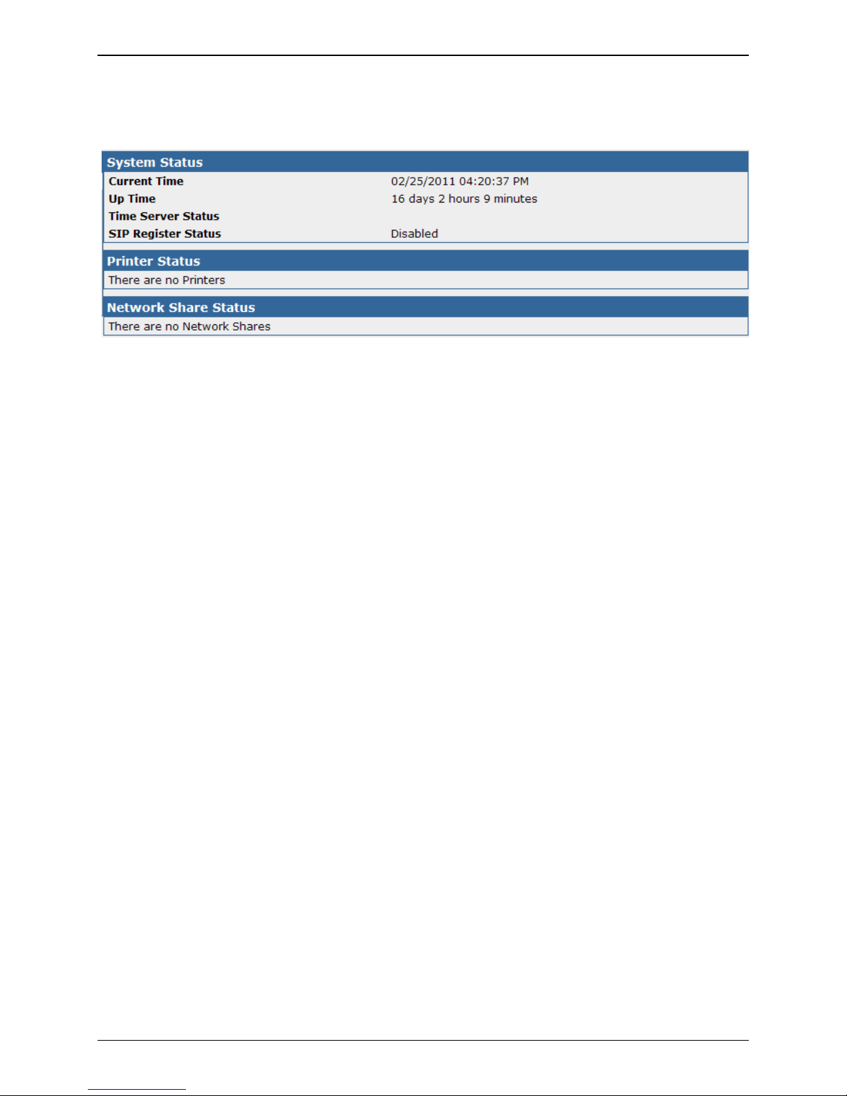
System Status
System Status
The
System Status screen provides many key pieces of information that can be used diagnostically or
simply as a confirmation of correct settings.
Current Time
This field displays the
set in the System Configuration: Time screen.
Up Time
This displays
reboot/reset or disconnection of power.
Time Server Status
This in
Time Server Status messages include: Disabled, Synchronizing, Synchronized at [time], and Failed
to synchronize: [error].
SIP Register Status
When
status of the FF240-IP registering to the registrar.
the running, total time that the FF240-IP has been in operation since the last
dicates the status of the Time Server currently in use.
"Use Registrar" is checked in the Fax Configuration | SIP settings section, this shows the
current time and date on the FF240-IP unit. The format for this display is
Printer Status section
Printer Status
This displays
Printers section.
Network Share Status section
Network Share Status
This displays
Configuration: Shares section.
Multi-Tech Systems, Inc. FF240-IP Admin User Guide 20
the current status of each printer that has been set up in the System Configuration:
the current status of any network shares that have been configured in the System
Page 21
Chapter 3: Web Management Interface
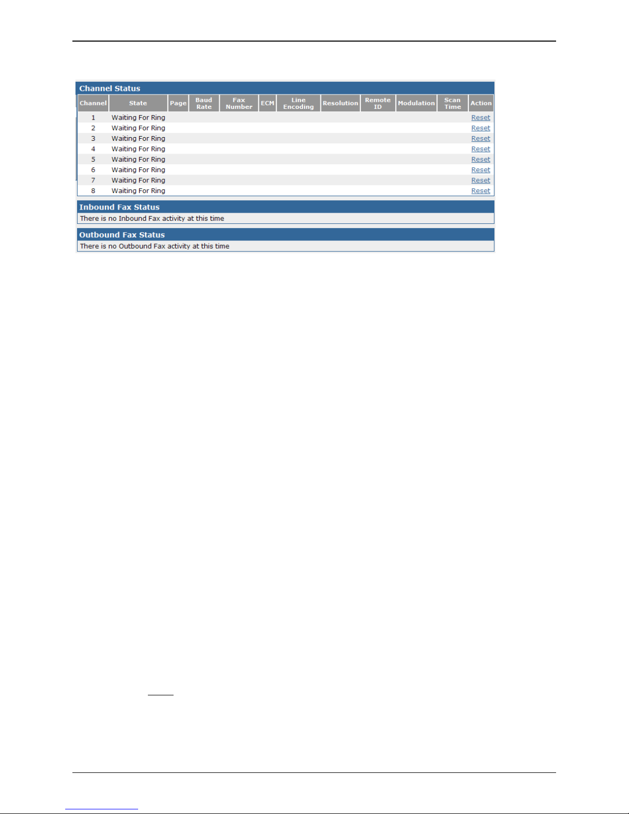
Fax Status
Fax Status details the current state for several key items. Here also the administrators can view and
change the state of the channels.
Channel Status
Channel
This column
State
This column
Connected, and Busied Out.
Pages Sent/Recd
This colu
Baud Rate
This column
Fax Number
This colu
ECM
This column shows if Error
Line Encoding
This column shows the
Resolution
This column shows the resolution
will be transmitted as.
Remote ID
This column
Modulation
This colu
Action
This option is
displays the sequential channel number associated with each installed T.38 port.
displays the current state that the channel is in. Messages include: Waiting for Ring,
mn displays the total number of pages that a channel has sent or received.
displays the baud rate for the channel.
mn displays the fax number associated with the channel.
Correction Mode is on or off for the channel.
line encoding set for this channel.
(vertical scan line type: ‘fine’, ‘standard’, etc.) that the page
displays the received identification from the remote connection.
mn shows the modulation set for this channel.
only available to an administrator.
Reset
Clicking on this link will reset the channel.
Multi-Tech Systems, Inc. FF240-IP Admin User Guide 21
Page 22

Chapter 3: Web Management Interface
Inbound Fax Status
Inbound Fax Status displays information pertaining to each fax that is incoming, divided into a variety of
categories.
State
This column
displays the state of a fax that has not yet been completely received.
Messages include: receiving or delivering.
Start Time
This shows th
e time that the inbound fax was initiated.
Channel
This colu
mn displays the channel number associated with each installed T.38 port.
Extension
This will
show the extension number where the fax will be routed to (if any).
Recipient
This will
display the recipient Username or channel ID.
Remote ID
This shows the ID informa
tion sent from the fax originator.
Pages Received
This will
show the total number of pages received.
Multi-Tech Systems, Inc. FF240-IP Admin User Guide 22
Page 23
Chapter 3: Web Management Interface
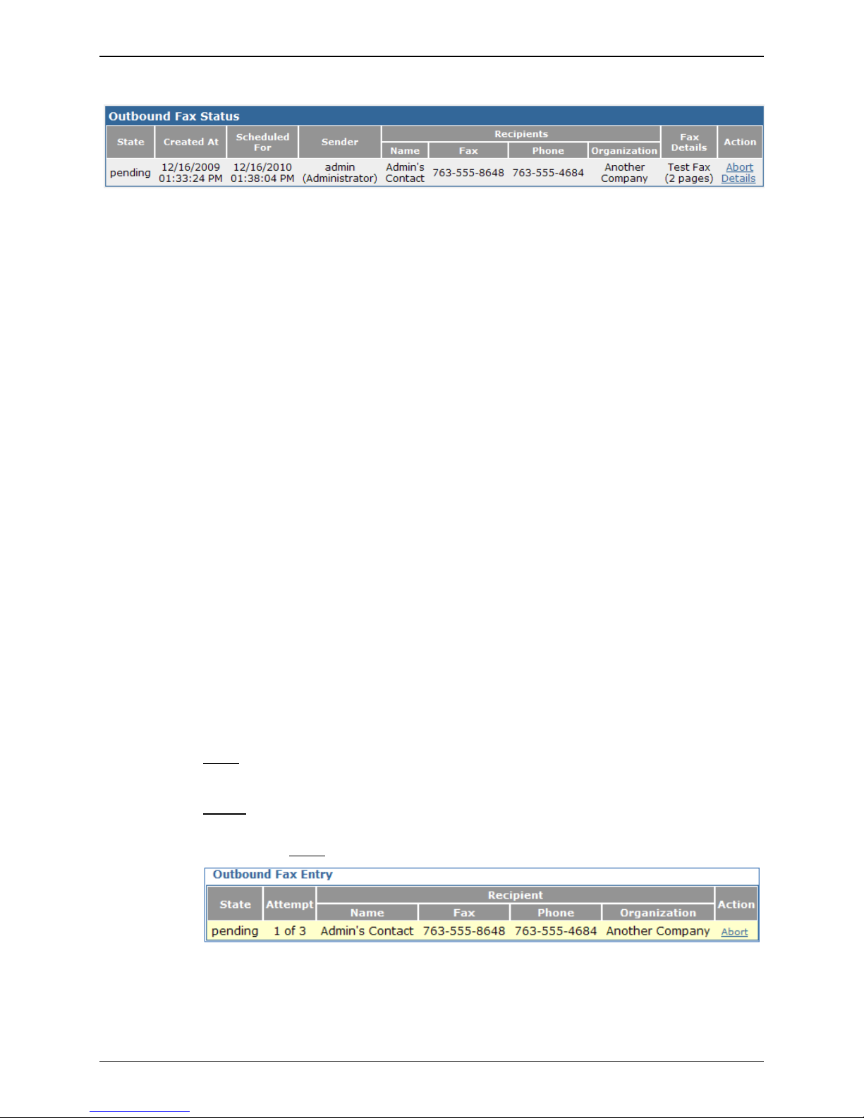
Outbound Fax Status
Outbound Fax Status displays information pertaining to each fax that is set to be sent, divided into a
variety of categories. There is also an Action section for aborting the fax before it is sent.
State
This column
displays the state of a fax that has not yet been sent or completed being sent.
Messages include: new, pending and sending.
Created At
This shows w
hen the outbound fax was initially queued.
Scheduled For
If the fax in the Outbox is scheduled to be sent at a ti
me other than immediately, this column
will show the scheduled time.
Sender
This shows th
e sender name and username of the party associated with the fax to be sent.
Recipients
Name
Displays the
name of the party intended to receive the fax.
Fax
The telephone number that is intended to receive the fax.
Phone
The voice telephone number of the recipient.
Organization
Name of the business or company intended to receive the fax.
Fax Details
This shows th
e pertinent pages of the outbound fax.
Action
These are
links to specific actions for individual outbound faxes.
Abort
This will cancel all further attempts to send this fax.
Details
Clicking this link will bring up a new windows with details of this specific fax. You may
also select to Abort
from this window.
Multi-Tech Systems, Inc. FF240-IP Admin User Guide 23
Page 24
Chapter 3: Web Management Interface
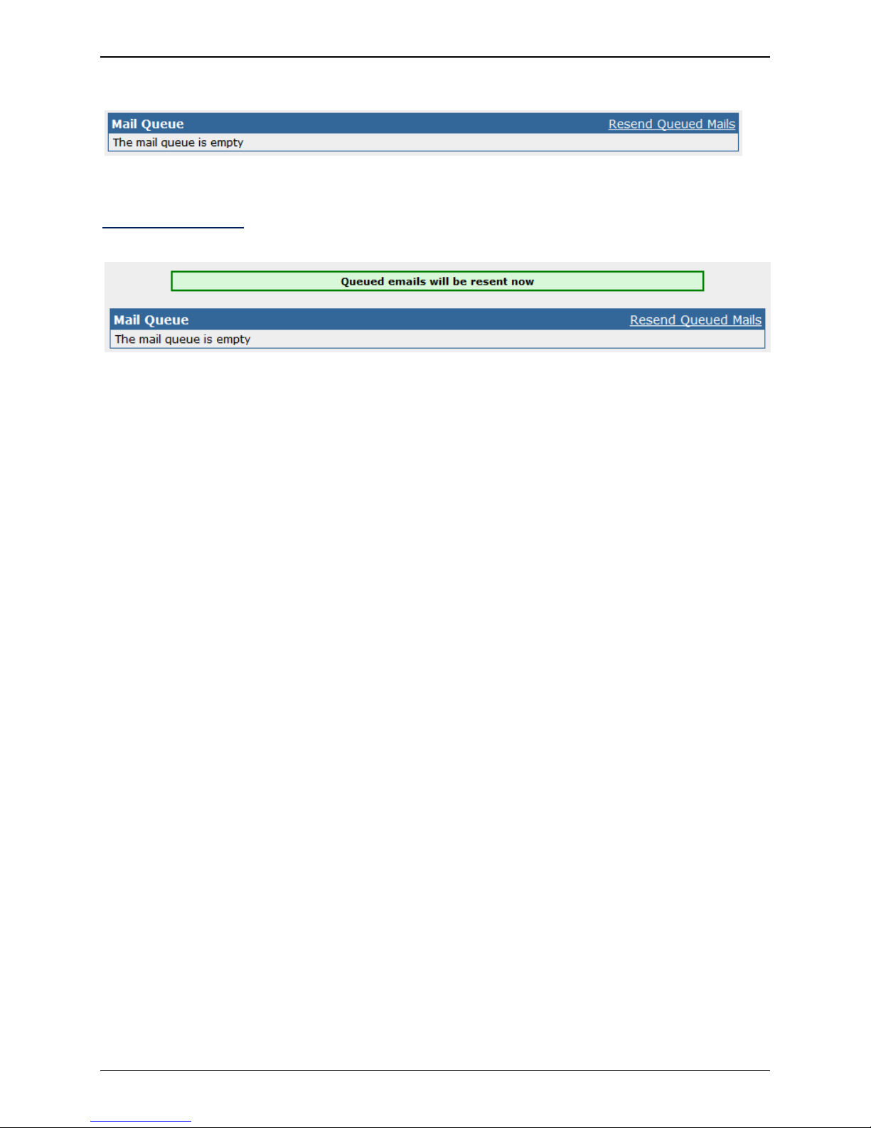
Mail Queue
The Mail Queue displays a list of emails residing in the queue waiting to be completed. Information is
broken into six sections.
Resend Queued Mails
Clicking on this link will tell the FF240-IP to resend all mail items in the queue immediately.
Date
This column
displays the date the email was created on.
Size
This column shows the size of the mail
message in bytes.
Sender
This colu
mn displays the user name of the party sending the email.
Recipient
This column
displays the intended target of the email.
Type
This column shows the
delivery type of file that is to be sent; e.g. local, remote.
Delivery Message
This column shows information about the resul
t of the delivery attempt.
Multi-Tech Systems, Inc. FF240-IP Admin User Guide 24
Page 25
Chapter 3: Web Management Interface
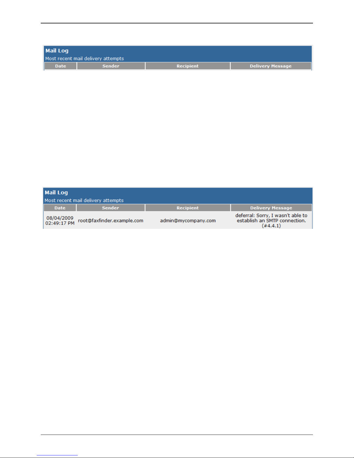
Mail Log
The Mail Log displays recent delivery attempts, listed from most recent to oldest.
Date
This colu
Sender
This column
Recipient
This column
Delivery Message
This column
For example, if there was a problem, SMTP error messages can be shown here; e.g. deferral: Sorry, I
wasn’t able to establish an SMTP connection. (#4.4.1).
mn displays the date that this mail entry was attempted.
displays the sender of this particular mail attempt.
displays the recipient for this attempted mailing.
displays a message showing the result of the mail delivery attempt.
Multi-Tech Systems, Inc. FF240-IP Admin User Guide 25
Page 26
Chapter 3: Web Management Interface
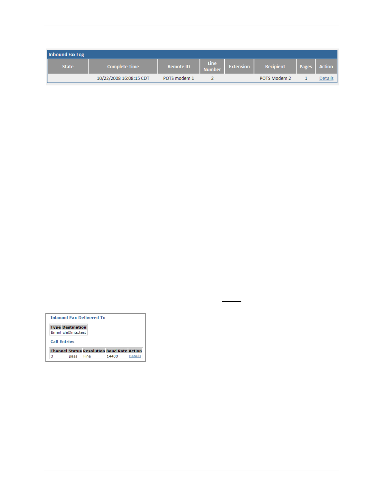
Inbound Fax Log
The Inbound Fax Log is a running tally of all of the faxes received by the FF240-IP unit. The individual logs
have several categories that are tracked. Descriptions are below.
State
This will
received, error – partial fax, and delivery failure.
Complete Time
This logs the
depends on the settings chosen in System Configuration | Time.
Remote ID
This will
Channel
This will
show the current or final state of the fax in question. States include: complete, error – no page
time at which that the incoming fax was successfully received. The format displayed
display the identification associated with the received fax.
show which channel received the fax.
Extension
This column
displays the extension that received the fax (if any).
Recipient
This colu
mn shows the identification of the recipient of the fax.
Pages
This
displays the number of pages that were received.
Action
This category shows actions that can be
taken with this log file. Details
show more specifics about the fax received as shown below.
is the only option here, which will
Multi-Tech Systems, Inc. FF240-IP Admin User Guide 26
Page 27
Chapter 3: Web Management Interface
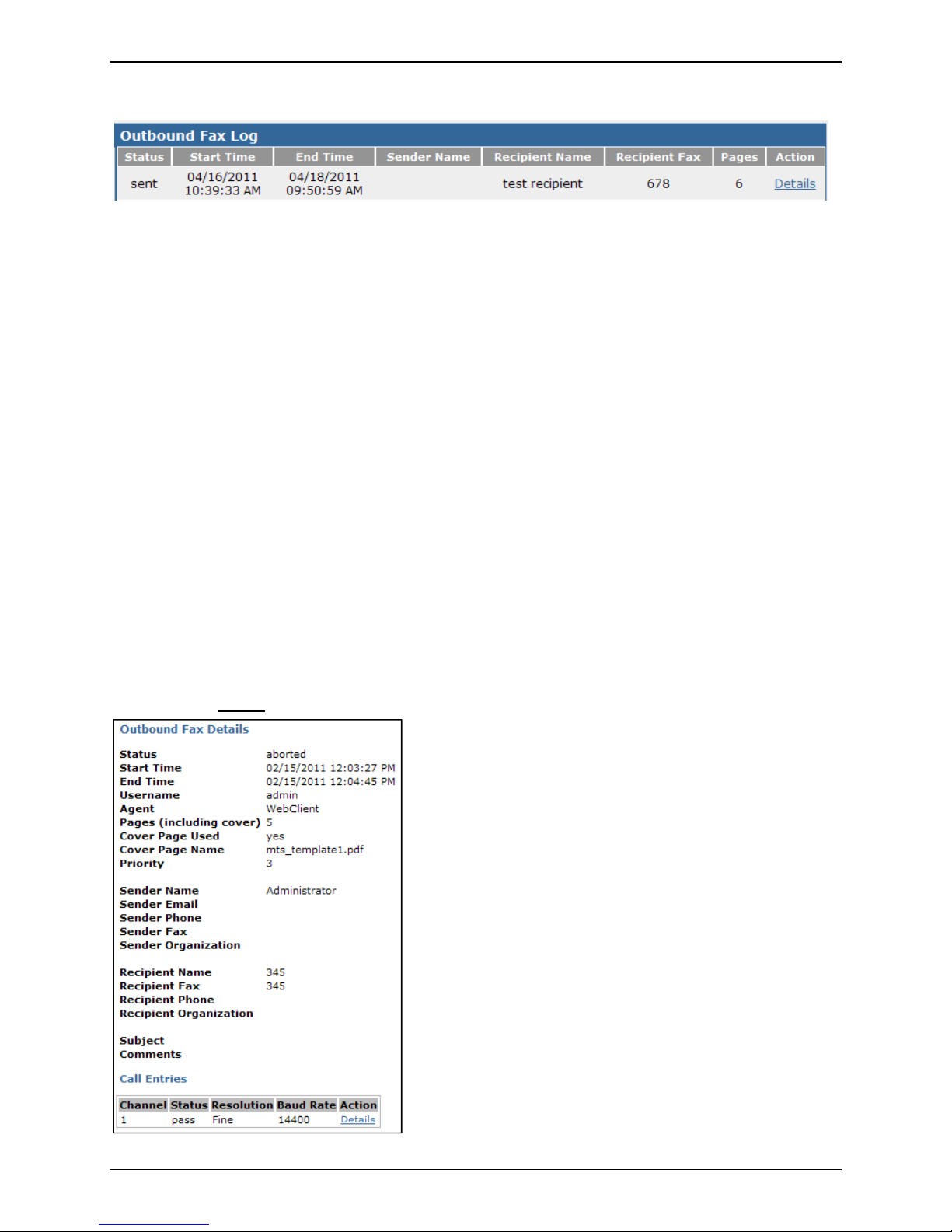
Outbound Fax Log
The Outbound Fax Log is a running tally of all of the faxes sent by the FF240-IP unit. The individual logs
have six categories that are tracked. Descriptions are below.
Status
This colu
failed.
Start Time
This column
End Time
This column
Sender Name
This column
mn displays the final result of the outgoing fax. Status messages include: sent, aborted and
displays the time that the transmission was started.
displays the time when the fax transmission completed.
displays the user name of the sending party.
Recipient Name
This colu
mn displays the name entered as the intended receiver of the fax.
Recipient Fax
This column
displays the fax number entered as the intended destination of the fax.
Pages
This colu
mn shows the number of pages in the outbound fax.
Action
Clicking on
the Details
link will bring up a pop-up window with further information concerning this fax.
Multi-Tech Systems, Inc. FF240-IP Admin User Guide 27
Page 28
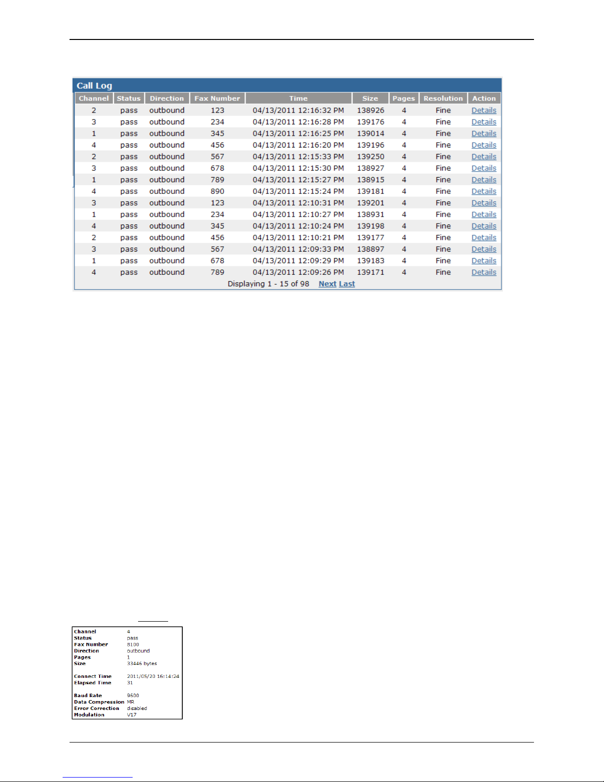
Call Log
Channel
This colu
Chapter 3: Web Management Interface
mn displays which channel the logged fax used.
Status
This column
displays the current state that the outgoing fax is considered to be in. Status messages
include: pass, aborted and failed.
Direction
This column shows which direction the l
Fax Number
This column
displays the phone number that the fax was logged on.
Time
This column
displays the time when the fax transmission completed.
Size
This column
displays the size.
Pages
This colu
mn displays the name entered as the intended receiver of the fax.
Resolution
This colu
mn displays the resolution used during the fax transmission.
Action
Clicking on
the Details
link will bring up a pop-up window with further information concerning this fax.
ogged fax went: either inbound or outbound.
Multi-Tech Systems, Inc. FF240-IP Admin User Guide 28
Page 29
Chapter 3: Web Management Interface
System Configuration Section
Network
Network Configuration
This section is for entering the specific
By factory default, the FF240-IP ships with the IP address 192.168.2.1 for setup purposes. After setup
and prior to connecting to your live network, enter the needed parameters for proper operation on the
network where the FF240-IP is to operate.
network settings needed for the FF240-IP to run on your network.
Hostname
the hostname that will be associated with this FF240-IP unit. This is what will be used in
Enter
conjunction with Store and Forward faxing through email. The Fax server will check the
hostname entered here and in Fax Configuration | Store & Forward Fax (T.37): Additional Hosts.
If an email comes from an email client not listed in either of these locations, that email will be
rejected.
Description
Here you
IP Address
Enter
for the first time, remember that once this has been changed, you will have to be on the same
network to make further changes.
Subnet Mask
Enter
255.255.255.0, though your network may be different.
Default Gateway
Enter
gateway is what allows the FF240-IP to contact network addresses outside of the local network.
This is necessary for contacting an internet time server or SMTP server.
Primary DNS
Enter
resolution of IP addresses. Changing this value will require a reboot of the unit.
Secondary DNS
Enter
reboot of the unit.
Save button
When you
away from this page, else your changes will be lost.
may enter a custom description for this network connection.
the IP address that has been set for this FF240-IP unit. If you are setting this FF240-IP up
the subnet mask that has been set for this FF240-IP unit. A typical subnet mask is
the IP address of the default gateway on the network for this FF240-IP unit. The default
the primary domain name server (if any) that this FF240-IP unit will use for name
the secondary DNS server (if any) for this FF240-IP unit. Changing this value will require a
have entered your information, be sure to click the save button before navigating
Multi-Tech Systems, Inc. FF240-IP Admin User Guide 29
Page 30
Chapter 3: Web Management Interface
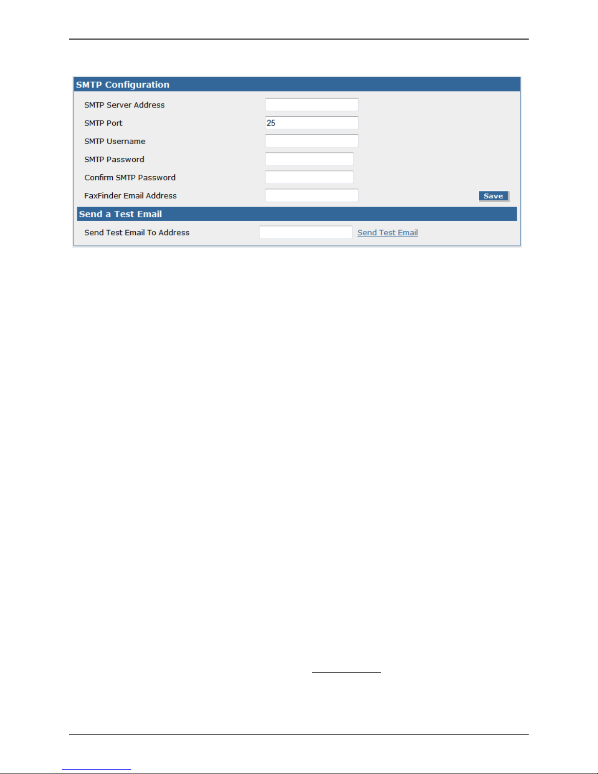
SMTP
The SMTP section contains the information needed to setup email usage with the FF240-IP, as well as a
way to test the setup by sending an email.
SMTP Configuration
SMTP Server Address
the IP address of your simple mail transfer protocol server here. This can be either an IP
Enter
address or Hostname. This is where emails will be sent.
SMTP Port
the SMTP port to be used here (the default value for SMTP is 25).
Enter
SMTP Username
If your S
for validation on the email server.
SMTP Password
If ne
Confirm SMTP Password
Re-en
FaxFinder Email Address
When a
noreply@'Hostname' (Hostname is the text entered in at System Configuration | Network|
Hostname) unless there is something entered in this FaxFinder Email Address field. If this has a
value in it, that value will appear in the ‘from’ field for emails from the FaxFinder. This is true for
all emails the FaxFinder send unless the email is for a fax received. Then the ‘from’ address is the
Fax ID.
Save button
When you
away from this page, else your changes will be lost.
MTP server requires authentication, enter the username that the FF240-IP unit will use
cessary for authentication, enter the password associated with the above username.
ter the password in order to avoid possible errors in the password previously entered.
n email is sent from the FaxFinder, the ‘From’ field in that email will be ffmailer-
have entered your information, be sure to click the save button before navigating
Send a Test Email
Send Test Email To Address
an email address here that you would like to send a test email to for verification that the
Enter
settings entered are correct and then click the ‘Send Test Email
Multi-Tech Systems, Inc. FF240-IP Admin User Guide 30
’ link.
Page 31

Chapter 3: Web Management Interface
Time
Time Configuration
Correct ti
enter a preferred time server as well as your preferences for time and date display format.
me settings are important for logging and verification purposes. This section allows you to
Time Server
Select a
time server from the choices available in the drop-down box or you may also select
‘none.’ When you select None, use the Set Time and Set Date at the bottom.
Custom Time Server
Here you
may enter the name or address of a time server different from those available in the
drop-down list.
Synchronize Every
the interval of time that you want the FF240-IP to synchronize with the time server. This is
Enter
only valid if you have selected a time server.
Time Zone
the time zone where the FF240-IP will be located from the drop-down list. Changing the
Select
time zone requires a reboot of the FF240-IP for it to take effect. A pop-up will alert you that a
reboot will be performed, to which you may select cancel if you do not want to reboot at this
time.
Date Format
the format that you want the date to be presented in. Key: ‘M’ is for month, ‘D’ is for day
Select
and ‘Y’ is for the year.
Time Format
the time format that you want information presented in (options are 24 or 12 hour).
Select
Save button
When you ha
ve entered your information, click the save button before navigating away.
Set Current Time
Set Time (24 hour) hh:mm:ss
Enter
or verify that the time is what you expect it to be. Key: ‘H’ is for hour, ‘M’ is for minute and
‘S’ is for seconds. This is only for when the Time Server has been set to “None.”
Set Date [MM/DD/YYYY]
or verify that the date is what you expect it to be. Key: ‘M’ is for month, ‘D’ is for day and
Enter
‘Y’ is for the year. This is only for when the Time Server has been set to “None.”
Set button
When you
have the time and date you want, click the Set button before leaving this page.
Multi-Tech Systems, Inc. FF240-IP Admin User Guide 31
Page 32

Chapter 3: Web Management Interface
Printer
Here you can add the printers available to the FF240-IP. Until the first printer is added, the section states
‘There are no Printers.’ Click the Add
Printers
The Add
and Advanced Setup screens are detailed in the next section. Clicking the Add link will bring up
the Add Printer screen where you can add a printer to be used by the FF240-IP.
Printer Name
This displays
the name you have entered for this printer.
Printer Make
This will
display the maker of the printer selected when you added the printer.
Printer Model
This displays
the model selected for this printer.
link to add a printer.
Description
This column
will display any descriptive text that is entered for this printer, e.g. “East end
printer.”
Device URI
This will
Help
http://hostname:631/ipp/port1.
display the text string that is the Uniform Resource Identifier of the printer. There is a
link on the Add Printer page that shows valid URI types; e.g. socket://192.168.2.250 or
Action
There are
three available action links:
Print Test Page
This will print a standard test page to the printer to ensure proper function.
Edit
This will open a new screen for editing the printer information. This screen is identical to
the Add Printer screen.
Delete
This will delete the printer.
Multi-Tech Systems, Inc. FF240-IP Admin User Guide 32
Page 33

Chapter 3: Web Management Interface
Add Printer
The Add Printer and the Edit Printer screens are identical, the only difference being that the Edit Printer
screen will already contain information previously entered.
Printer Make
the manufacturer of the printer you are adding from the drop-down list. If you do not see
Select
the manufacturer (make) of your printer, you can use the Generic selection.
Printer Model
Select
the model of the printer you are adding from the provided list. If you selected Generic
above, the selections here will be generic as well.
Printer Name
a name to associate with this printer that users will understand.
Enter
Description
nter a description of the printer you are adding. It is often useful to put the location of the
E
printer here; e.g. “East end printer.”
Device URI
Enter
the Uniform Resource Identifier for this printer. Similar to a website URL, the URI identifies
the location of a printer on the network. There is a Help
socket://192.168.2.250 or http://hostname:631/ipp/port1.
Advanced Setup
Advanced Setup
This will
bring up the Common UNIX Printing System (CUPS) page. This page is provided for
advanced printing configuration and job control.
Note: This page is provided using the GNU General Public License software agreement. A copy of
the GNU GPL can be found on the product CD.
Save button
When you
have entered your information, be sure to click the save button before navigating away from
this page, else your changes will be lost.
Cancel button
Clicking on
the cancel button will cause you to lose all information entered and return you to the
previous screen.
link that shows valid URI syntax; e.g.
Multi-Tech Systems, Inc. FF240-IP Admin User Guide 33
Page 34

Chapter 3: Web Management Interface
Shares
The shares screen allows the administrator to create a place for faxes to be sent for retrieval by more
than one person. Anyone with network rights to the shared folder can view the faxes sent there.
Creating a location to share access to multiple users can be a good way to ensure that faxes are
responded to in a timely manner, especially in a sales environment. Others benefits are the ability for
employees to cover for each other when someone is out of the office and for electronic archiving of
faxes to a single location.
Note: It may be necessary to enable ‘Simple File Sharing’ when using a Microsoft Windows network.
Shared Resources
Domain/Workgroup
the domain where the FF240-IP will be operating. This box is pre-populated with the
Enter
default value of ‘WORKGROUP.’
Save button
When you
have entered your information, be sure to click the save button before navigating
away from this page, else your changes may be lost.
Network Shares
By clicking on the
Add link, you will bring up the Add Network Share screen where shares can be added.
UNC / Location
This column
will display the Universal Naming Convention identifier or location entered for this
shared resource.
Username
This column
will display the username for the network that is associated with this shared
resource.
Action
Connect
Clicking this link will connect you to the shared resource.
Edit
Clicking on this link will allow you to edit the parameters of this shared resource.
Delete
Clicking this link will delete the shared resource from use by the FF240-IP unit.
Multi-Tech Systems, Inc. FF240-IP Admin User Guide 34
Page 35

Chapter 3: Web Management Interface
Add Network Share
After entering and saving a new network shared resource, you will see the message “Network Share
updated” appear at the top of the screen. The network share is a common location when received faxes
may be routed to. For those with access rights to this shared location, all information is accessible for
use.
UNC / Location
the Universal Naming Convention identifier or network location in this box. An example of
Enter
a UNC or location would be ‘//server/service’ or ‘\\server\service.’
Username
the username that has write access to the shared location. This can be a general account
Enter
or one specific to the folder that is to be shared.
Password
the password associated with the above username.
Enter
Confirm Password
ter the password in order to avoid possible errors in the password previously entered.
Re-en
Save button
When you
have entered your information, be sure to click the save button before navigating
away from this page, else your changes will be lost.
Cancel button
Clicking on
the cancel button will cause you to lose all information entered and return you to the
previous screen.
Multi-Tech Systems, Inc. FF240-IP Admin User Guide 35
Page 36

Chapter 3: Web Management Interface
Certificates
A site certificate is needed for a browser to allow access to the FF240-IP unit. This certificate is selfsigned, so your browser will likely show a security warning (which simply means the certificate is not
authenticated by a third party) before you can continue. Use this page to replace the default certificate
with the one that contains details specific to your installation. These values are for identification
purposes only. Creating a new certificate will require a reboot of the FF240-IP. A pop-up will warn of this
and allow you to cancel the changes if necessary.
After generating a new certificate, you may have to make an allowance in your web browser to log back
in to the FF240-IP unit. Browsers will not allow access without a valid certificate and the FF240-IP does
have a valid certificate, but it is self-signed (i.e. no third party verification), so your browser displays a
warning about this. You may safely continue (Internet Explorer), or in the case of Firefox, temporarily
add the FF240-IP certificate to the exception list. Details on how to add to an exception list can be found
in Chapter 2.
Generate Server Certificate
Common Name
the common name associated with the certificate. This should be set to the Hostname or
Enter
IP address, depending on which you will use when connecting to the FF240-IP. A web browser
will use this field to check for a valid certificate. No more than 64 characters are allowed.
Days
the number of days that the certificate is valid. No more than 3 digits are allowed.
Enter
Country
Enter
the country that the certificate is valid for using in, using its two letter code. A search for
“country codes” at www.iso.org will give you a list if needed. The code US is for the United
States.
State/Province
the state or province that the certificate is valid for. No more than 64 characters are
Enter
allowed.
Locality/City
Enter
the city or locality that the certificate is valid for. No more than 64 characters are allowed.
Organization
Enter
the name of the organization that the certificate is valid for. No more than 64 characters
are allowed.
Multi-Tech Systems, Inc. FF240-IP Admin User Guide 36
Page 37

Chapter 3: Web Management Interface
Generate Server Certificate continued:
Email Address
Enter
the email address of who is responsible for the FF240-IP (typically the administrator). This
field may be left blank. No more than 64 characters are allowed.
Generate button
Click on
the generate button to create the certificate based on the information above. This will
require an immediate reboot of the unit (a pop-up window will allow you to cancel the action).
Server Certificate
The
details of the verification certificate for the FF240-IP unit are displayed in this box.
Multi-Tech Systems, Inc. FF240-IP Admin User Guide 37
Page 38

Chapter 3: Web Management Interface
Save/Restore
After you have entered the specific settings to have your FF240-IP working in your environment, coming
here to save those settings is a good idea. Were something to happen and you lost what had been
entered, you can easily reset the unit to working condition if you have a saved configuration file.
Save/Restore Configuration
Save Config
The Save Config link will save settings entered during this session to a configuration file that can
be retrieved later using the restore configuration option.
Click on the Save File button, and then click OK. When saving a configuration file, try and use a
place that will help you remember where it is stored.
Restore Factory Defaults
Clicking this link will reset all data in the FF240-IP to the default values that were set at the
factory. Use this with caution. This will reboot the FF240-IP.
Restore Config
Click on the Br
owse button after the box to navigate to a previously saved configuration file.
Once selected, click the Restore button to have those saved values used once again.
Restore button
Once
a saved configuration file has been entered in the restore config box, clicking the restore
button will use those values that were retrieved above, to set up the FF240-IP with the values
saved in that configuration file. This will reboot the FF240-IP.
Multi-Tech Systems, Inc. FF240-IP Admin User Guide 38
Page 39

Chapter 3: Web Management Interface
Software Update
There may be occasions where features are refined or added to the FF240-IP unit. Such features will be
available through updating of the software that exists in the FF240-IP.
Software Update
Update Source
This is the
URL for software updates, when they are available. Clicking the Default
return the factory URL for checking update availability.
Current Version
This displays
the current software version installed on your FaxFinder.
link will
Check for Updates button
Clicking this button will allo
w a FaxFinder with Internet access to check the designated site for a
newer version of software and subsequently download and install it.
Important: Do not power off the FF240-IP during the update process.
Note:
When the FF240-IP unit is being updated, the HTTPS port (TCP 443 by default) and TCP port 80
(the traditional HTTP port) need to be forwarded (open) to the FF240-IP if there is a firewall or other
security software that will potentially block those ports.
License Upgrade
If you have
purchased additional T.38 ports to upgrade your FF240-IP, you can enter those license keys
here. Instructions for this process are included with the License Upgrade Kit.
Current Channels
This line displ
ays the current number of channels installed. [Maximum of 8]
Hardware ID
This displays
the Hardware ID of your physical FaxFinder unit (for use when purchasing
additional 2-channel licenses).
Current License Key
displays the current License Key in use on your FaxFinder.
This
New License Key
Purchasing o
ne or more License Upgrade Kits will allow you to use the upgrade process through
the provided website; enter the New License Key here and click the Upgrade License button.
Upgrade License button
the Upgrade License button to apply the New License Key you entered above to increase
Click
the number of channels available (there is a maximum of 8).
Important: Do not power off the FF240-IP during the upgrade process.
Multi-Tech Systems, Inc. FF240-IP Admin User Guide 39
Page 40

Chapter 3: Web Management Interface
Reboot
Reboot Unit
Clicking on
the Reboot button will log off the current user and restart the unit. Please make sure that
there are no faxes being sent before you click reboot. The FF240-IP will not be able to send or receive
faxes during the reboot process.
Debug
The Debug page is for those rare occasions when standard troubleshooting is not enough and debugging
files need to be gathered and sent to Multi-Tech for more in-depth analysis.
Current System Log Level
Select the lev
Options are: Info, .Emergency, Alert, Critical, Error, Warning, Notice, Debug.
el of logging that Multi-tech has requested form the drop-down list.
Save
Once
you have selected the correct level of logging, click the save button and then use the Download
Logs link above the Save button.
Download Logs link
Clicking on
the Download Logs link will bring up the File Download window. Click on the Save
button and select a location that will be easy to remember. Once this zipped file is created,
follow the instructions given by Multi-Tech for sending it on.
Packet Capture
Clicking on
the Start button will begin the packet capture process on this unit (generally for
troubleshooting purposes). When you are finished, click the Stop button (the Start button transforms
into this). This will change the screen and allow you to download the capture via the provided hyperlink.
Multi-Tech Systems, Inc. FF240-IP Admin User Guide 40
Page 41

Chapter 3: Web Management Interface
Fax Configuration Section
SIP / T.38 Configuration
This screen is where you will need to set all of the necessary settings for your FaxFinder IP to work
properly on your network.
If you need to reset all of the SIP and T.38 settings on this screen back to their factory default settings,
click on the Defaults
blank entry.
link in the upper right corner. Be aware that the default for many of the boxes is a
Multi-Tech Systems, Inc. FF240-IP Admin User Guide 41
Page 42

Chapter 3: Web Management Interface
SIP
Transport Protocol
SIP call setup messages are transmitted using UDP. There is currently no option for TCP.
SIP Proxy/Gateway
This displays the IP address of the SIP device the FF240-IP will communicate with when sending faxes.
This could be a SIP proxy, SIP Gateway or IP PBX.
SIP Domain
Enter the SIP domain into the box if necessary.
Authorization Required
Check this if the SIP proxy or the registrar the FF240-IP is communicating with requires authentication.
Username
Enter the Username if you checked the “Authorization Required” box.
Password
Enter the Password if you checked the “Authorization Required” box.
Confirm Password
Re-enter the authorization Password.
Local Port
Enter the local port used for SIP. Default is 5060.
SIP Proxy Port
Enter the SIP Proxy port if necessary. Default is 5060.
User Registrar
Check this box if the FF240-IP needs to use a registrar for SIP call routing.
Registrar
Enter the SIP registrar IP address.
Registrar Port
Enter the registrar port if necessary. Default is 5060.
Expires
Enter the registrar expiration time in seconds. Default is 3900 seconds.
Multi-Tech Systems, Inc. FF240-IP Admin User Guide 42
Page 43

Chapter 3: Web Management Interface
T.38
Fax ID
Enter the Fax ID you want the FaxFinder to send out.
Fax Method
Use the drop-down box to select T.38 Re-invite, T.38 Pass Through or T.38 Direct as your fax method.
Fax Codec
Check the box for each fax codec you want in use. G 7.11 Alaw and G 7.11 µlaw are available depending
on your Fax Method (T.38 Re-invite and T.38 Pass Through only).
Redundancy Level
Enter a redundancy level for the FaxFinder. Default is 3.
Max Buffer
Enter the maximum buffer to be used for the FaxFinder. Default is 4000.
Extension Source
Select the extension source to be used by the FaxFinder.
Options are: SIP to Header or SIP Diversion Header.
Extension Digits
Select the manner in which extension digits are used.
Options are: Use All; Use First Only; Use Last Only.
Channel Reservation
If you want channels reserved for specific use only, enter the number of channels reserved for Inbound
Only or Outbound Only in these fields.
Max Rate
Select the maximum fax transmission rate for the channels from the drop-down list.
Options are: 2400; 4800; 9600; 12000; 14400; 16800; 19200; 21600; 24000; 28800; 31200; 33600.
Error Correction
Choose if you want to have fax Error Correction on or off.
Dial Prefix
Enter a dial prefix to be applied to all channels if necessary. The dial prefix is appended as a prefix to all
faxes being sent.
Jitter Buffer Delay
Enter the jitter buffer delay (in milliseconds). Default is 30 ms.
Max Datagram
Enter the maximum datagram size allowed. Default is 948.
Extension Length
Enter the extension length allowed for the channels.
Save button
When you
have entered your information, be sure to click the save button before navigating
away from this page, else your changes will be lost.
Multi-Tech Systems, Inc. FF240-IP Admin User Guide 43
Page 44

Inbound Routing
Chapter 3: Web Management Interface
There are several ways an incoming fax can be routed: They can be routed globally or by extension. A
global routing entry will route every incoming fax to the defined global routing Fax Destination.
Incoming faxes from PBXs that provide DTMF digits to the FF240-IP can be routed based on the
extension digits to recipients as defined in the Recipient Fax Destination.
A Destination can be an existing User’s Email, a printer where you would ‘print on receive’ to a defined
printer, an Email where the Fax would be delivered to an email address, to the trash (the fax is simply
thrown away), or a share where the incoming fax is copied to a defined network share location.
General Setup
Email Size Limit
a size limit for inbound emails in Kilobytes. Any incoming faxes that are over this set limit
Enter
will be split into multiple emails that are below the limit, i.e. a fax from a sender that is too large
to be accepted by the email server will be automatically recreated as multiple smaller faxes for
the recipient so that the fax is not rejected.
Fax Output Format
Choose the f
ormat (either .PDF or .TIFF) that you want inbound faxes to be presented as.
Email Fax Details
Check this box if you want detailed information about the fax included in the email body for
incoming faxes.
Multi-Tech Systems, Inc. FF240-IP Admin User Guide 44
Page 45

Global Routing
Fax Destinations
This displays
recipient.
Action
Here you w
Routing screen are found below.
Add Destination (Global)
Select
to add the related information in the second field. Destinations available are: Email, Share, Print
and Email to User. Your choice here will determine what information you must provide before
clicking the update button.
Chapter 3: Web Management Interface
a destination for inbound faxes to always be routed in addition to their intended
ill find a link to Edit
the parameters set for Global Routing. Details of the edit Global
the global destination from the drop down list. Some of these selections will require you
Save button
When you are finished with your selection, click the Update button to set the global destination.
Cancel button
Clicking on the cancel button will cause you to lose all information entered and return you to the
previous screen.
Default Routing
For any in
coming fax that does not have a proper recipient destination, default routing is the catch-all
destination.
Fax Destinations
This displays
a destination for inbound faxes to be routed when there is no recipient or
extension.
Action
Here you w
ill find a link to Edit
destination other than Admin.
the default routing. Click on the Edit link to assign a default
Multi-Tech Systems, Inc. FF240-IP Admin User Guide 45
Page 46

Chapter 3: Web Management Interface
Recipients
This will display a list of inbound recipients. There are four action links available: Add
and Delete All
.
Add Recipients
Clicking on the Add link will bring up
the Add Recipients screen.
Extension
Enter the phone number of the recipient to be added.
Name
Enter the name of the recipient to be added.
, Import, Export
Destinations (Extension)
After adding a Recipient, the Add Destination section for this extension will appear.
Add Destination (to created extension)
Click the Add
link to select the default destination for this recipient (Email, Share, Print,
Trash, Email to User).
Import Recipients from CSV
Clicking on
the Import link will bring up the import screen.
CSV File
Click on the Browse button to navigate to an existing CSV file to add them to the
recipient list. The format for the CSV file is detailed below.
Existing Recipients
Select to either merge the new CSV file with the existing data or to replace the existing
data with the new CSV information.
Import button
Click on the import button to begin the process or all settings will be lost when you
navigate away.
Multi-Tech Systems, Inc. FF240-IP Admin User Guide 46
Page 47

Chapter 3: Web Management Interface
Inbound Recipients CSV Import Format
Fields
Extension,Description,Destination type,Destination value
Values
• Extension: numerical extension
• Description: The description for the recipient. Does not need to be repeated for multiple
destinations for the same extension. Only the description for the first destination is used.
• Destination type: One of the following types "Email", "Share", "Print", "User", and "Trash"
• Destination value: The value of the destination appropriate for the type (shown below):
o Email: email address
o Share: The full UNC path of the network share. (The share must already be set up on the
FF240-IP)
o Print: The name of the printer. (The printer must already be set up on the FF240-IP)
o User: The name of the existing FF240-IP user to email
o Trash: No value needed
Example:
Extension,Description,Destination type,Destination value
1000,John Smith,Email,jsmith@example.com
1000,John Smith,Print,myprinter
1001,Bill,User,bill
1001,Bill,Share,\\server\sharename\folder
9999,Junk,Trash,
Fields may be quoted with double quotes. A header row is optional.
Export Recipients to CSV
This will export the
current recipients list to a CSV file. Click Save on the pop-up window and select a
location for the file to be saved at.
Delete All
This will permanently delete all entries in the recipients list.
Multi-Tech Systems, Inc. FF240-IP Admin User Guide 47
Page 48

Chapter 3: Web Management Interface
Outbound
The Outbound page contains a selection box for allowing simultaneous faxing and archiving options.
Outbound Options
By che
cking the “Allow simultaneous faxing to the same number” box and clicking the Save button, you
allow the FF240-IP unit to send multiple faxes to the same phone number at the same time. This is
beneficial for fax configurations where a single number is mapped to multiple lines or a trunk.
By default, this option is off and the FF240-IP will send faxes to the same number one at a time.
Save button
When you
button before navigating away from this page, else your changes may be lost.
have checked or unchecked the “Allow simultaneous…” box, be sure to click the save
Outbound Archive
Enable Outbound Archive
this box if you want to enable outbound archiving.
Check
Archive Format
the format that you want the archive saved as. Options are PDF or TIFF with .pdf being
Select
the default selection. Be aware that these are image files that cannot be searched for specific
words or edited – it is basically a “picture” of the information.
The naming convention used for archived files is:
fax_outbound_#dialed_date_time_faxID#.
The number dialed, date, time and fax ID number are variable; “fax_outbound” will always be
the first words of the file.
Archive Directory
the location of a shared folder that you want the archive to be saved to or click the
Enter
Browse
setup, any entries or use of the Browse
link to manually locate the shared folder. If you do not have a shared folder already
link will result in an error.
Save button
After set
ting the options that you want, click the Save button before navigating away from the
page or your settings will be lost.
Multi-Tech Systems, Inc. FF240-IP Admin User Guide 48
Page 49

Chapter 3: Web Management Interface
Outbound Approval
Outbound approval gives an administrator the ability to restrict outgoing faxes through several
categories. The details of each section are found on the next page.
Multi-Tech Systems, Inc. FF240-IP Admin User Guide 49
Page 50

Chapter 3: Web Management Interface
0
k
Outbound Approval Setup
If you want to use any, some or all of the outbound approval options, you must check the ‘Enable
Outbound Approval’ box here.
Approvers
The ‘Approvers’ section allows you to a
dd users who are able to allow faxes to be sent out. By default,
the Admin account is here.
Add
Click on the Add link to add the selected user from the drop-down list to the list of those who
can approve outbound faxes.
Approved Fax Numbers
The ap
proved fax numbers section is for adding phone numbers or portions of phone numbers that are
always approved. Numbers added in this section will bypass the checks of the Approved Users section.
Add
Click on the Add link to add a phone number or add a portion of a phone number with the
asterisk (*) wildcard to allow for variants (i.e. digits that follow an approved area code or local
prefix).
Clicking the Add link will create an empty text field in this section where you can add the phone
number, then click the Save button at the bottom of the page to confirm it.
Approved Users
pproved Users section lists users that can send faxes without needing to be approved. By default,
The A
the admin account is entered here. Click on the Add link to add more exempt users.
Add
Clicking on the Add link will create another drop-down list box where you can select the user
from the entire list of users entered in the FF240-IP unit. When you have added all the users
that you want added to the approved list, click the Save button at the bottom of the page to
ensure your entries are not lost.
Reminders
nders in the form of an email message will be sent to all users listed in the ‘Approvers’ section at
Remi
the top of the section. By default, three time intervals are listed: 30 minutes, 60 minutes and 1440
minutes. Click on the Add link to add more times or the Remove link to delete times.
Add
Click on the Add link to create a new text box for entering a time (in minutes) for the FF240-IP to
send an email reminder to all Approved users.
Outbound Approval Report
If you wan
t reports of the approved faxes to be sent to the ‘Approvers’, check the ‘Enabled’ box here.
Select the format that you want the report sent as from the drop-down list. Both .csv and .xml formats
are available, with CSV being the default selection.
The table at the bottom allows you to customize the frequency in which the report is generated and
sent out. This is the same style as used in the Fax Log purge
Examples of Report Settings:
Send a report every Sunday at 7:00 pm: Send report at 11:00 pm on the first every month:
Minutes is set to 0 Minutes is set to
Hours is set to 19 Hours is set to 23
Day of Month is set to Every day of month Day of Month is set to 1
Month is set to Every month Month is set to Every month
Day of Week is set to Sunday Day of Week is set to Every day of wee
.
Multi-Tech Systems, Inc. FF240-IP Admin User Guide 50
Page 51

Chapter 3: Web Management Interface
Cover Pages
Here you can view or delete a cover page from the supplied pages created by Multi-Tech, or you can
import (Add
appendix. Cover pages must be in the PDF version 1.4 format. The Opt-Out section is available if you use
the FF240-IP for advertisement purposes. The “Editable cover pages
FTP site where the templates are available in the .sla format.
) one of your own. For tips on creating custom cover pages, please see the customization
” link will take you to the Multi-Tech
Opt-Out
placement of the Opt-Out information will depend on the cover page in use. Note that some cover
The
pages are written to expect a certain type of Cost Free method to be used; e.g. “Email _____ to opt-out
of further fax communications.”
Phone
Enter
the phone number that can be called to reach you or someone who can remove a phone
number from a contact list (opt-out of receiving faxes from this unit or your business).
Fax
the fax phone number that will accept opt-out faxes (to remove the recipient from contact
Enter
list of this unit or your business).
Cost Free
a ‘cost-free’ method (email address, toll-free telephone or fax number, Website, etc.) that
Enter
recipients can use without incurring a cost, and be removed from the contact list of this unit or
your business.
Save
After e
ntering your Opt-Out information, click the save button.
Multi-Tech Systems, Inc. FF240-IP Admin User Guide 51
Page 52

Chapter 3: Web Management Interface
Cover Pages
PDF Cover pages to be used with your FF240-IP unit need to be version 1.4 to work properly.
The Editable cover pages
Add
Click on the Add
link will take you to the .pdf files on the Multi-Tech website.
link to open the Add Cover Page screen detailed below.
Cover Page
This column li
sts the file names of available cover pages as links. Clicking on the name will open
the file for viewing.
Action
Delete
Clicking this link will delete the cover page permanently from the FF240-IP unit.
Add Cover Page
Clicking
the Add link will take you to the Add Cover Page screen where you can browse to an existing
cover page design (PDF file type) that you want to make available as an option on this FF240-IP unit.
Even though the browse button allows multiple file types to search for, only PDF files are allowed.
Cover Page
Enter the path and name of the cover page that you want to add or click the Browse button to
manually navigate to the location of the created cover page.
Add button
Click the add button to save the cover page you entered or browsed to and save it to the FF240IP unit. Once added, the cover page is saved in the unit for all users.
Cancel button
Click the cancel button to discard changes and return to the previous screen.
Multi-Tech Systems, Inc. FF240-IP Admin User Guide 52
Page 53

Chapter 3: Web Management Interface
Store & Forward Fax (T.37)
Store and Forward fax (or T.37) is described in detail with examples in a later chapter. Here we are
describing the parameters for T.37 that can be input into the FF240-IP unit through the web interface.
Store & Forward Fax (T.37): Parameters
Enable T.37
To allow the
use of Store and Forward faxing on this FF240-IP unit, check this box, else it will not
be allowed.
Require Authentication
the Require Authentication box to force users to have a valid username and password to
Check
use Store and Forward faxing.
Set User From Envelope Sender
this box to set the User from the envelope sender.
Check
Default Scheduling Priority
the priority for scheduling store and forward faxing. The range is 0 to 5, with 0 being the
Select
highest priority. This setting will come in to play when there are more faxes in the queue that
need to be sent out than there are available channels.
Maximum Tries
the maximum number of tries that you want the FF240-IP to attempt without a successful
Enter
completion before considering the fax as failed.
Interval Between Tries
the time in seconds that you want the FF240-IP to wait between unsuccessful transmission
Enter
attempts.
Multi-Tech Systems, Inc. FF240-IP Admin User Guide 53
Page 54

Chapter 3: Web Management Interface
Email Fax Receipt
Select the condition that will trigger an email to the sender. There are three options here:
Failure – An email receipt will only be sent if the fax fails.
Always – On completion (success or failure) an email receipt will be sent.
Never – The FF240-IP will not send a receipt for any result.
Fax Attachment with Receipt
Use t
his drop down box to set the attachment type for fax receipts. Options are PDF, TIFF or
None with the default set to .pdf format.
Include Cover Page
this box if you want the cover page selected above to be included, otherwise no cover
Check
page will be attached.
Default Cover Page
the cover page to use by default when using Store & Forward faxing.
Select
Use Email Body as Comments
this box if you want to have the body of the email inserted into the fax comments section.
Check
Save button
When you
have entered your information, be sure to click the save button before navigating
away from this page, else your changes may be lost.
Store & Forward Fax (T.37): Additional Hosts
Recipient Host
This will display a list of additional
hostnames and IP addresses that the FF240-IP will accept for
Store and Forward faxing. If your hostname is example.FF240-IP.com, and you want to support
T.37 faxing from other hostnames (e.g. mycompany.FF240-IP.com) this is where you would
enter the additional hostname.
Action
These are
the action item links available for the T.37 host.
Edit
This will bring up the editing screen for changing the recipient host.
Delete
This will delete the recipient host.
Add
Located in the title bar at the right margin, the Add link will bring up the Add Recipient Host
screen where you can add a new recipient host as noted above. Make sure to click the Save
button after entering the information or it will be lost once you browse away or close the
screen. If you do not wish to add a new recipient, click on the Cancel button and you will be sent
back to the Store & Forward Fax screen.
Multi-Tech Systems, Inc. FF240-IP Admin User Guide 54
Page 55

Chapter 3: Web Management Interface
0
Fax Log
The interval at which the fax log files are deleted can be adjusted here. By default, the logs are removed
each day at midnight.
Fax Log Purge
Here is w
select multiple options by clicking and dragging or by holding down the Shift or Control key while
selecting. Clicking on the Examples
here the timing of log purging is set. The different columns allow for many settings. You can
link will open a pop-up displaying examples as shown below.
Email Expired Entries to Administrator
If you want have the fax logs sent as an email attachment to the administrator before they are deleted,
check this box.
Minutes
Should you want to purge log files at intervals that are not on the hour, you can set the minutes.
Hours
This corresponds to the hour of the day when using a 24-hour clock (e.g. Hour 19 is 7 pm).
Day of Month
The Day of Month counts forward from the first day, so if you want to delete all fax logs on the
th
of every month, this would be set to 5.
5
Month
As a long term option, you can set the logs to be purged only in a specific month.
Day of Week
Log files can be set to be cleared on a specific day of the week, or every day of the week.
Email Expired Entries
If you want to keep the FF240-IP unit clear of log files, yet wish to retain the log files, you can
check this to have the log files emailed to the administrator email address.
Examples of Fax Log Purge Settings:
Examples are provided to help understand the specific columns.
To purge logs every Sunday at 7:00 pm: To purge logs at 11:00 pm on the first every month:
Minutes is set to 0 Minutes is set to
Hours is set to 19 Hours is set to 23
Day of Month is set to Every day of month Day of Month is set to 1
Month is set to Every month Month is set to Every month
Day of Week is set to Sunday Day of Week is set to Every day of week
Purge Logs Now
Clicking on this link will delete all currently stored logs now instead of waiting for the purge time set
above.
Multi-Tech Systems, Inc. FF240-IP Admin User Guide 55
Page 56

Chapter 3: Web Management Interface
Users Section
The FF240-IP Users section of the FF240-IP unit displays a list of all of the users that have been entered
or imported into the unit itself. With the exception of the default admin account, all users can be edited
or deleted as needed. Users are the definitions of people that have access to the FF240-IP for sending
faxes. Each user will have a list of Contacts that they use to send faxes. The user information is used gain
access to the FF240-IP to send a fax via the web interface Send Fax page or an external Web API client
such as the FF240-IP Client software.
It is important that each user of the FF240-IP is entered in to the unit so that their contact list is
populated. All contacts are stored in the FF240-IP unit and the Client software will retrieve this list when
the user installs the software. When a user adds or deletes a contact, it is done to the database of the
FF240-IP unit, as it is the only place where this information is kept. Users of the FF240-IP system should
log in to the unit and add to their Contact list manually (the Add link) or automatically (the Import link).
When importing a contact list, the user can choose to overwrite any existing information, or simply add
the new information (the ‘Merge’ option).
FaxFinder Users
This section
Contact lists for individual users. Contact lists are the primary source for information when sending out
faxes. The Phone, Fax and Organization fields will be used to populate the corresponding fields on the
cover page.
will list all of the users added to the FF240-IP unit. Click on the Edit
Add / Import / Export / Delete All
A User
done manually through the Add
available. The entire User list can also be Exported to a CSV file for use with other FF240-IP units
or programs. The Add, Import and Export screens are shown below.
Full Name
This displays
Username
This
Email
This displays
Phone
This displays
contacting the user regarding a fax they have sent or received.
must first be added before they can add Contacts to their account. Adding a User can be
link or automatically through the Import link if a CSV file is
the text entered as the full name for a user.
displays the username.
the email address associated with the user account.
the phone number associated with the user. Typically this is a voice number for
action item to see the
Fax
This displays
Multi-Tech Systems, Inc. FF240-IP Admin User Guide 56
the fax number associated with the user account.
Page 57

Chapter 3: Web Management Interface
Organization
This displays the organization (if any) that is associated with the account.
Action
Edit
Clicking on the Edit link will bring up the editing screen for a user. You will also see this
list of Contacts associated with this user. The same options are available: Add, Import,
Export and Delete All. Contact lists use four primary pieces of information for speed and
simplicity of use: Name, Fax Number, Phone Number and Organization.
Edit username
Here you w
ill find all of the previously entered User information. Every field except the
assigned Username can be changed. Click on the Update button to save any changes.
Edit Contacts for username
Here is
the list of contacts that have been associated with this account. Links are
available to Add, Edit, Import, Export or Delete All for entries here.
More contacts can be added manually or imported from a CSV file. Please note that
imported files with matching names will overwrite the current information. You can also
Export this contact list to a CSV file for possible importation by another user to save
time when contact lists are shared. Each entry can be edited or deleted in the Action
column.
Edit Groups for username
Here is
the list of groups that have been associated with this account.
There are links for Adding, Editing or Deleting All of the listed groups.
Multi-Tech Systems, Inc. FF240-IP Admin User Guide 57
Page 58

Chapter 3: Web Management Interface
Add
Clicking the Add link will bring up the Add FF240-IP User screen. Here you will enter the information to
be associated with the new user account.
Import
CSV File
Click on the Browse button to navigate to an existing CSV file to import. See Contact CSV File
Import Format below for specifics on the fields imported.
Existing Users
Select to either merge the new CSV file with the existing data or to replace the existing data
with the new CSV information.
Import button
Click on the import button to begin the process or all settings will be lost when you navigate
away.
Cancel button
This will return you to the Users screen.
Contacts CSV Import Format
Fields
Name, Fax Number, Organization, Phone Number
Values
• Name: name of the contact
• Fax Number: contact's fax number
• Organization: contact's company name
• Phone Number: contact's phone number
Example:
Name,Fax Number,Organization,Phone Number
Fred Johnson,111-555-1000,Another Company,111-555-1001
Contact 2,1234,Company Two,5678
Fields may be quoted with double quotes. A header row is optional.
Multi-Tech Systems, Inc. FF240-IP Admin User Guide 58
Page 59

Chapter 3: Web Management Interface
Users CSV Import Format
There are two types of records in the User CSV format: a User record type and a Contact record
type. The first column determines which type of record the line is, so you may see both types in
one CSV file.
User Record
Fields
Type, Username, Password, Full Name, Email, Phone, Fax, Organization
Values
• Type: must be "User"
• Username: user's username
• Password: user's password
• Full Name: user's full name
• Email: user's email address
• Phone: user's phone number
• Fax: user's fax number
• Organization: user's company name
Example:
Type,Username,Password,Full Name,Email,Phone,Fax,Organization
User,john,my_password,John Smith,jsmith@acompany.com,612-555-1234,612-555-2222,"A
Company, Inc."
User, joe, joe_password, Joe Doe, jdoe@workplace.com, 612-555-1234, 612-555-2222,
Workplace
Contact,john,Fred Johnson,111-555-1000,Another Company,111-555-1001
Contact,joe,Contact 2,1234,Company 2,5678
Fields may be quoted with double quotes. A header row is optional. A header row is any
row that starts with "Type,".
Contact Record
Fields
Type, Username, Contact Name, Fax Number, Organization , Phone Number
Values
• Type: must be "Contact"
• Username: username of the user this contact belongs to
• Contact Name: name of the contact
• Fax Number: contact's fax number
• Organization: contact's company name
• Phone Number: contact's phone number
Example:
Type,Username,Password,Full Name,Email,Phone,Fax,Organization
User,john,my_password,John Smith,jsmith@acompany.com,612-555-1234,612-555-2222,"A
Company, Inc."
User, joe, joe_password, Joe Doe, jdoe@workplace.com, 612-555-1234, 612-555-2222,
Workplace
Contact,john,Fred Johnson,111-555-1000,Another Company,111-555-1001
Contact,joe,Contact 2,1234,Company 2,5678
Fields may be quoted with double quotes. A header row is optional. A header row is any
row that starts with "Type,".
Multi-Tech Systems, Inc. FF240-IP Admin User Guide 59
Page 60

Chapter 3: Web Management Interface
Export
Click on the Save File button, then click OK to save the current Users as a Comma Separated Value file.
Delete All
This will permanently delete all users in the list.
Contacts Section
The contacts section will list all of the available recipients for the user that is currently logged in. This is
separated into four sections for organization and ease of use (Personal, Global, Personal Groups and
Global Groups).
Personal
The personal contact section shows all of the personal contacts added by the currently logged in user.
Contacts for n
There are
four links for managing personal contacts: Add
Name
displays the contact name as entered.
This
Fax Number
This displays
the fax number entered for this contact.
, Import, Export and Delete All.
Phone Number
This displays
Organization
This displays
Action
Edit
Clicking on the Edit link will open the editing screen so that the personal contact information can
be changed.
Delete
Clicking on the Delete link will permanently remove this contact from the FF240-IP.
Multi-Tech Systems, Inc. FF240-IP Admin User Guide 60
the voice phone number entered for this contact.
the organization that has been entered for this contact.
Page 61

Chapter 3: Web Management Interface
Global
The global contact group displays all of the global contacts entered by the administrator for use by all
users.
Global Contacts
There are
four links for managing global contacts: Add
Name
This
displays the contact name as entered.
Fax Number
This displays
the fax number entered for this contact.
Phone Number
This displays
the voice phone number entered for this contact.
Organization
This displays
the organization that has been entered for this contact.
, Import, Export and Delete All.
Action
Edit
Clicking on the Edit link will open the editing screen so that the personal contact information can
be changed.
Delete
Clicking on the Delete link will permanently remove this contact from the FF240-IP.
Multi-Tech Systems, Inc. FF240-IP Admin User Guide 61
Page 62

Chapter 3: Web Management Interface
Personal Groups
The personal groups screen will display all personal groups available for the logged in user.
Personal Groups
There are two links available for personal groups: Add
Name
displays the contact name as entered.
This
Description
This will
Action
Edit
Clicking on the Edit link will open the editing screen so that the personal contact information can
be changed.
Delete
Clicking on the Delete link will permanently remove this contact group from the FF240-IP.
display the description entered for the created group.
and Delete All.
Global Groups
The global groups screen will show all of the global groups created by the administrator that are
available to all users.
Global Groups
There are
two links available for global groups: Add
Name
This
displays the contact name as entered.
Description
This will
Action
Edit
Clicking on the Edit link will open the editing screen so that the personal contact information can
be changed.
display the description entered for the created group.
and Delete All.
Delete
Clicking on the Delete link will permanently remove this contact group from the FF240-IP.
Multi-Tech Systems, Inc. FF240-IP Admin User Guide 62
Page 63

Chapter 3: Web Management Interface
Send a Fax Screen
The Send Fax screen is a one page form for sending faxes directly from the FF240-IP unit when accessed
from a web browser.
Multi-Tech Systems, Inc. FF240-IP Admin User Guide 63
Page 64

Chapter 3: Web Management Interface
Send Fax
Sender Information
If a cover page is selected (the ‘Yes’ check box detailed below), much of the sender information will
be already populated in the cover page from what is provided for the logged-in user. This can be
changed if needed, or left as is.
Name
Enter
the name of the sender here.
Organization
the name of the sending organization (if needed) here.
Enter
Phone Number
the sending phone number here (a voice line that should be used to contact the sender
Enter
should there be any questions or problems).
Fax Number
the fax number where you want to receive faxes.
Enter
Email Address
Here you
may provide an email address that can be used by recipients for contacting the sender.
Recipient Information
Find Recipient
Select from
the drop-down menu how you would like to enter your recipients:
Personal Contacts
Personal Groups
Global Contacts
Global Groups
Enter Recipient Info
Enter Recipient Info and save as Personal Contact
Contact/Group
Use the
drop-down box to select a recipient from the contact list that is associated with the Find
Recipient list selected above. Once selected, the Name, Organization/Description. Phone
Number and Fax Number below will be automatically populated with that information from the
Contact list.
You need to click the Add Recipient button after making this selection if you are not
Note:
adding the recipient manually.
Name
If not alrea
dy populated, enter the name of the intended recipient.
Organization/Description
If not alrea
dy populated, enter the organization (if any) of the recipient. If a group was entered,
the description will be here.
Fax Number
If not alrea
dy populated, enter the fax number of the recipient.
Phone Number
If not alrea
dy populated, enter the voice phone number of the recipient.
Multi-Tech Systems, Inc. FF240-IP Admin User Guide 64
Page 65

Chapter 3: Web Management Interface
Add Recipient button
Click this button to add a selected or manually entered recipient to the list. Repeat the process
to add more recipients.
Recipient list
The
current list of added recipients is listed here. If needed, you can Delete
individual entries.
Cover Page Information
Include cover page with this fax?
Select Yes or
No for your choice.
Select Cover Page
Choose a cover page
from the drop-down box.
Subject
a subject for the fax here.
Enter
Comments
Enter any
comments needed for this fax transmission.
Attachments
Browse to
any attachments that you need to add. Click the Add Another Attachment button if there is
more than one attachment needed. Allowed attachment types are: .PDF, .TIF, .TIFF, .TXT, .PS.
Options
Max Tries
Enter
the number of tries that you want the FF240-IP to attempt before aborting the fax.
Priority
st
the transmission priority for this fax. The range is from 1
Select
Priority to Low. The default
setting is Medium priority.
Retry Interval (seconds)
the number of seconds for the FF240-IP to wait between unsuccessful transmission
Enter
attempts. The default is 300 seconds.
Send a receipt
Select from
the drop-down box under what condition you want a receipt sent. There are three
options here:
Failure – An email receipt will only be send if the fax fails.
Always – On completion (success or failure) an email receipt will be sent.
Never – The FF240-IP will not send a receipt for any result.
Fax Attachment with Receipt
Select from the drop-down menu the f
ormat of the receipt attachment: .PDF, .TIF or None (do
not attach). The default is PDF formatting.
Send Fax button
en all of the send fax information is completed, click the send fax button to activate this fax.
Wh
Navigating away from this screen or exiting the browser without clicking the send fax button will
clear all data and the fax will not be sent.
Multi-Tech Systems, Inc. FF240-IP Admin User Guide 65
Page 66

Chapter 3: Web Management Interface
Logout
Clicking this navigational link will log you out of the FF240-IP unit. This is always a good practice to
follow when you are finished using the FF240-IP, especially if you were logged in with an administrators
privileges for security reasons. There is no screen associated with the Logout link – after clicking Logout,
you will be redirected to the Login screen.
Multi-Tech Systems, Inc. FF240-IP Admin User Guide 66
Page 67

Chapter 4 – Client Software
Installation
The Client software is for general use of the FF240-IP, but it needs to be associated with a FF240-IP unit
for proper operation. Your administrator should provide the software or a location where it can be
obtained from. You will need to install the Client software on your PC and set the FF240-IP that it is to
work with. You will need to be logged in with administrator rights before starting any installation.
Installation
A. Insert the FF240-IP Product CD into the CD-ROM drive of the client PC. If the CD does not auto
start, use Windows Explorer to navigate to your CD drive and launch the installation program by
double-clicking on cd_start.exe file on the CD. From the menu presented, click the Software
button.
From the new screen presented, select the Client Software button to install the Multi-Tech
FF240-IP Client software for using the FF240-IP unit.
- or -
Retrieve the software installer from the location provided by your administrator.
Double-click the filename (default is
FFClientTSinstall is for Windows Terminal Services only.
FFClientInstall.msi) to begin the installation. The file labeled
Important: If you have any old versions of the FF240-IP client software installed (for any FF240-IP
model family), please uninstall that prior to installing the new version. The FF240-IP client
utilizes Windows Add or Remove Programs utility in the Control Panel.
Multi-Tech Systems, Inc. FF240-IP Admin User Guide 67
Page 68

B. At the Welcome screen, click Next.
Chapter 4: Client Installation
C. At the Select Installation Folder screen, browse to the desired file location for the FF240-IP
client software. In most cases, the default file location is recommended.
Clicking on the Disk Cost button will show you the size of the software being installed as well as the
available disk space of the target drive.
When the destination location is correct, click Next.
Multi-Tech Systems, Inc. FF240-IP Admin User Guide 68
Page 69

Chapter 4: Client Installation
D. At the Confirm Installation screen, click Next to begin the installation.
A transient screen (“Installing FF240-IP Client Software”) will appear while files are being copied.
E. The FF240-IP Client software can place a shortcut in the Startup directory so that the client
software will start automatically when the PC is booted.
F. You will be asked if you want the Client software to automatically launch when the installation is
complete. Select your preference.
Note: This window does not pop-up during a Terminal Services installation.
Multi-Tech Systems, Inc. FF240-IP Admin User Guide 69
Page 70

Chapter 4: Client Installation
G. You will be asked whether or not you want to associate .tif and .cpg files with the Multi-Tech Tiff
Viewer. Click Yes (unless you prefer to use a different viewer program). The .cpg files become
associated with the legacy Cover Page software that is used with the legacy FaxFinder FFx20
models.
If a Question screen appears asking "Warning - the extension .tif is already registered,
Overwrite?”; click Yes if you wish to use the TIFF viewer installed with the FF240-IP Client
Software. Click No if you prefer to leave the current association for viewing .tif files.
H. Then the Installation Complete screen will appear.
Click the Close button.
If you chose ‘Yes’ above to have the client software start after installation, you will see the
application icon down in your System Tray. Click on the icon and select “show FF240-IP Client
software” to use the program.
Multi-Tech Systems, Inc. FF240-IP Admin User Guide 70
Page 71

Chapter 4: Client Installation
Push Installation Method
Push Installs of the Client Software
The FF240-IP Client installer is now available as an MSI package. This provides the ability to perform
remote installation using Microsoft Group Policy, SMS, as well as other third party tools. The installer
can be run like any other Windows software installer and it can also be invoked from the command line
using the Windows Installer command ‘msiexec’. Previous versions of the FF240-IP Client (1.08.xx and
older) must be uninstalled before upgrading.
Note: The User Account Control (UAC) feature of Windows Vista and Windows Server 2008 will need to
be turned off for push installations to complete successfully.
The installer supports the following options when being used from the command line or remote
installation:
• Set a different install directory:
o TARGETDIR=PATH (default is Program Files/Multi-Tech Systems/FF240-IP Client
Software)
• Add file associations for Multi-Tech TIFF Viewer and Cover Page Editor:
o ADDFILEEXT=1 (default is 0)
• Start the FF240-IP client after installation:
o LAUNCHPRODUCT=1 (default is 0)
• Automatically Start the FF240-IP Client
o LAUNCHPRODUCTONBOOT=1 (default is 0)
• Example command to install in silent mode with options:
o msiexec /i FFClient-x_x_x.msi /q TARGETDIR=”C:\FF240-IP Client” ADDFILEEXT=1
LAUNCHPRODUCT=1 LAUNCHPRODUCTONBOOT=1
• Example command to uninstall in silent mode:
o msiexec /x FFClient-x_x_x.msi /q
An example of how to perform a remote software installation using Microsoft Group Policy is available
from Microsoft’s website.
• Search for Knowledge Base article number 816102 at microsoft.com.
Client Install Shield Mass Uninstall
An MSI packa
ge is available on the web site, and the Installation CD, that can be used to mass un-install
the previous version of FF240-IP Client (versions before 1.08.xx).
• Example command to uninstall the Install Shield FF240-IP Client in silent mode:
o msiexec /i remove_installshield_faxclient.msi /q
Multi-Tech Systems, Inc. FF240-IP Admin User Guide 71
Page 72

Chapter 4: Client Installation
Setting the Usage Rights for the Printer
The printer that is installed into Windows for the FF240-IP to work requires some settings of the rights.
For Windows Server 2003, Windows XP and earlier:
The Windows account/user that is to "use" the printer, needs to have the "Print" permission associated
with (enabled on) their Windows account (regarding the printers security properties).
For Windows Vista, Windows 7 and later:
The Windows account/user that is to "use" the printer, needs to have the "Print" permission and the
"Manage Printers" permission associated with (enabled on) their Windows account (regarding the
printers security properties).
Associating Client Software and User with the FF240-IP Unit
After the FF240-IP client software is installed, you must associate it with one or more FF240-IP units.
Sometimes more than one FF240-IP unit is available for use. In some cases, certain client users might be
assigned to some FF240-IP units and not assigned to others. This procedure shows you how to make this
association so that faxes may be sent from a particular FF240-IP unit to the email inbox of your PC. To do
this procedure, you will need to know the IP address of the FF240-IP unit that you are able to use. You
should also be given a valid username and password for every unit that you can use. Be aware that an
individual FF240-IP client user can be associated with more than one FF240-IP unit. This could easily be
the case in an office that is large and/or an office that has a great deal of fax traffic.
The icon for the FF240-IP Client software application will appear in the Windows Start menu programs
selection. After installation, the Client Software starts up whenever the computer is booted if the ‘Yes’
option was chosen when the ‘Do you wish to start the FF240-IP Client automatically?’ prompt appeared
during installation. When running, a FF240-IP icon appears in the system tray area at the lower-right
corner of the screen. The FF240-IP Fax Client Software screen can be opened from either the Start menu
icon or the tray icon. If the Client Software is shut down, it can be re-opened from the Start menu or by
double-clicking on a file named FF240-IPClient.exe (or something very similar), which, following a typical,
default installation, is located at C:\Program Files\Multi-Tech Systems\FF240-IP Client Software\FF240IPClient.exe. When the client software is launched, it will reside in the System Tray be default.
System Tray Icon
Multi-Tech Systems, Inc. FF240-IP Admin User Guide 72
Page 73

Chapter 4: Client Installation
1. At the main screen of the FF240-IP Fax Client Software, click on Edit and select “Add FF240-IP” if
you know the IP address or Host Name of the FF240-IP, otherwise open the Tools menu and select
“Auto-Discover Devices” to have the Client software search the network for FF240-IP units.
Add FF240-IP Manually
Use Auto Discover to Locate FF240-IP
a. If you are using the Auto Discover Device method, click the ‘Search’ button to have the FF240-IP
Client software search the available network for FF240-IP units that are available.
Multi-Tech Systems, Inc. FF240-IP Admin User Guide 73
Page 74

Chapter 4: Client Installation
2. To add a FF240-IP when the IP address is known, select the FF240-IP model family from the Type
drop-down, enter the IP address “Server Address” field along with your Username and Password.
If you need to use a secure login, tick the ‘Use SSL’ checkbox.
If the Auto Discover Devices feature was used, you may Right-click and select Add or double Leftclick on the IP address or name of the FF240-IP unit that was detected. Use the ‘X’ in the upper right
hand corner to close the Auto Discover window after you have added it to the client.
3. Enter, in the appropriate fields, the Username and Password that the client will use when accessing
this FF240-IP unit. If the client is to be associated with multiple FF240-IP units, a different Username
and Password could be established for each. However, in most cases, it is advisable (for the sake of
simplicity and convenience) to use the same Username and Password for all FF240-IP units.
NOTE: The Username entered here must match the entry used in the “Username” field of the Users
screen on the FF240-IP Server. The password entered here must match the password
entered for this user.
The Username and Password are case-sensitive.
Click OK.
Multi-Tech Systems, Inc. FF240-IP Admin User Guide 74
Page 75

Chapter 4: Client Installation
4. A new FF240-IP entry should appear on the “Devices” tab of the FF240-IP Fax Client Software
screen.
The status of the newly registered FF240-IP unit may momentarily go from “Not logged in” to
“Logging in” to “Connected.” A FF240-IP x20 unit will show Idle instead of connected.
If it goes to Login Failure, then one of two things is wrong:
a. The IP address or domain name is wrong. If that is the case, delete that entry (by right-clicking
DELETE), and enter a new one;
- or -
b. The Username/Password combination may be wrong. Verify that the client Username/Password
combination (accessible by right-clicking and selecting Properties on the FF240-IP listed in the
Devices tab of the client software) matches the Username/Password combination assigned to
the client-user by the FF240-IP Administrator.
Note: Username and Password are case-sensitive.
Disassociating the Client from a Specific FF240-IP Unit
In this procedure, you will un-do the procedure “Associating Client with a Specific FF240-IP Unit.” This
situation might occur when changes are being made in the network faxing system. In any event, this
procedure severs the tie between your PC and a specific FF240-IP unit so that you will no longer be
connected to it for sending fax messages. (Faxes can be received in email form from the FF240-IP server,
despite disassociating from the FF240-IP server, as long as the receiving party is defined in the Inbound
Routing section of the FF240-IP unit.) In cases where the client is currently associated with more than
one FF240-IP unit, you will need to know the IP address of the specific FF240-IP unit from which you
want to disconnect.
1. Open the FF240-IP Client Software program and go to the Devices tab. Select the FF240-IP unit from
which you want to disconnect (you can identify the FF240-IP unit by its IP address or domain name),
Right-click on it and select delete.
2. Your FF240-IP Client Software will no longer be able to send faxes through this particular FF240-IP
unit.
Multi-Tech Systems, Inc. FF240-IP Admin User Guide 75
Page 76

Chapter 5 – FaxFinder-IP Operation
Introduction
This chapter describes the things that a user can do with the FF240-IP system. The software programs
involved are the FF240-IP Client Software and the Multi-Tech Tiff Viewer (or designated PDF viewer).
The FF240-IP Client Software interfaces with the FF240-IP Server and has its own user interface. When
previewing outgoing faxes, the PC’s operating system calls up the designated TIFF viewer to display the
outgoing fax. When viewing received faxes, the PC’s operating system calls up the appropriate viewer
(PDF or TIFF). The choice of file types (PDF or TIFF) is made in the FF240-IP Server software. Note that
client users can choose to display either on the Multi-Tech TIFF viewer or on a different (non-MultiTech) TIFF viewing program. Likewise, if the FF240-IP system distributes incoming faxes as PDF files, the
client can designate which PDF viewer to use. The Multi-Tech TIFF viewer is installed automatically with
the FF240-IP Client software.
Overview:
Sending Faxes
¾ The FF240-IP Schedule Fax Screen (New Fax)
¾ Send Fax with Client Software
¾ Send Fax by Printing
¾ Send Fax from Email (T.37)
¾ Send Fax from FF240-IP Web Interface
¾ Send Fax by Web API
Using the Client Software
¾ Details of Software Commands
o Add a contact
¾ Using the Cover Page Generator
¾ Using the Tiff Viewer
Multi-Tech Systems, Inc. FF240-IP Admin User Guide 76
Page 77

Chapter 5: FaxFinder-IP Operation
Sending Faxes
Sending faxes through the FF240-IP is quick and simple and offers a variety of methods that can be used
to accomplish this. This section will show all the possible ways to send a fax with the FF240-IP.
Depending on how your administrator has set up the unit, several or even all options may be available.
First, the FF240-IP Schedule Fax window will be explained as it is used for the majority of faxing through
the FF240-IP unit.
The Schedule Fax Screen (New Fax)
The FF240-IP Schedule Fax screen appears (a) when you double-click an item from the Print Capture tab
of the client, or (b) when you select the New Fax command from the File menu of the Client Software
screen or (c) when you Right-click an item in the Print Capture tab and select ‘Fax.’
There are four sections (called ‘panes’ hereafter) to the Fax Scheduler: the Recipients pane, the
Documents pane, the Options pane and the Cover Page pane. At the bottom are the two main function
buttons – one to send or schedule the fax and the other to cancel it entirely.
Device pane
device pane provides a drop-down list of all FF240-IP units available to this client. Select the unit
The
that you want this fax sent from.
Reconnect button
If you have multiple FF240-IP units available and the
the FF240-IP you want to send through and click the Reconnect button.
Multi-Tech Systems, Inc. FF240-IP Admin User Guide 77
unit you want to use is not selected, select
Page 78

Schedule Options pane
Options text box:
This text box will display ‘Send Immediately’ by default. If you want to schedule this
fax to be sent at a specific time or date, then you must click the Options button.
Options (button):
If you want to specify a time or date for the fax to be sent, you must click the Options
button which will open the Fax Scheduling Options window. The Options button will also allow
you to change the Maximum Attempts, Priority and Fax Receipt options from the default values.
Fax Scheduling Options
Chapter 5: FaxFinder-IP Operation
Send Immediately
By default, the ‘Send Immediately’ box will be checked which has the ‘Date’ and ‘Time’ fields
grayed-out.
By un-checking the ‘Send Immediately’ box, you can set a specific time and date for this fax to
be sent.
Fax Priority
You can select the level of priority for your fax from the drop-down list. The options are (in order
st
of highest priority first): 1
Priority; High; Medium/High; Medium; Medium/Low; Low.
The default priority is Medium.
Fax Receipt
Select the condition for receipt from this job. The options are: Always; Failure; Never.
The default receipt condition is Failure.
Fax Attachment with Receipt
If you have selected to receive receipts as attachments, you can select the format from this
drop-down list. Options are: None; PDF; TIFF.
The default attachment type is PDF.
Retry Interval
Enter the retry interval for instances where the fax does not complete.
The default retry time is 5 minutes and 0 seconds.
Multi-Tech Systems, Inc. FF240-IP Admin User Guide 78
Page 79

Chapter 5: FaxFinder-IP Operation
Recipients pane
Name (column):
Party to whom the fax will be sent. You cannot type in this window. When a recipient is
specified either from the Contacts or from the New Recipient window (the ‘+’ button), that
recipient’s name will appear in this field.
Fax Number (column):
Fax number to which the fax will be sent. You cannot type in this window. When
a fax number is specified either from the Contacts or from the Enter a Fax Recipient window;
that fax number will appear in this field.
Organization (column)
This column will display the organization associated with the recipient (if there is one). You
cannot type in this window.
+ (button): Brings up the New Recipient window. At this window, you enter the name and fax number of
the party to whom the fax will be sent.
— (button): Removes a selected (left-click to select) entry or entries from the Recipients list. You will be
prompted to confirm removal of the recipient(s) from the list of recipients. Multiple entries can
be selected by holding the Ctrl key (individually) or Shift key (all entries between) while clicking.
Contacts (button): Brings up the Select Contacts screen from which a fax recipient can be chosen (this is
retrieved from the user contacts stored in your user ID on the FF240-IP unit). If enabled on the
FF240-IP server, this will also display contacts from Microsoft Outlook. Multiple entries can be
selected by holding the Ctrl key (individually) or Shift key (all entries between) while clicking.
Documents pane
Document (column):
File name and type extension of document(s) to be transmitted as a fax.
+ (button): Click this button to add another document to the fax transmission. Only .tif, .pdf and .txt files
can be added with this.
— (button): Click this button to remove a document from the list of items to be faxed. You will be
prompted to confirm removal.
Recent Documents (button):
an item from the list will make the Add button available. Click the Add button to add the
attachment to the current fax.
Multi-Tech Systems, Inc. FF240-IP Admin User Guide 79
Clicking this will bring up a list of the most recent attachments. Selecting
Page 80

Cover Page pane
Use Cover Page (check box):
Check this checkbox to include a cover page with your fax.
Cover Page (drop-down selection box):
ticked. By clicking on the down arrow, you will see the selection of cover pages available from
the FF240-IP unit. Click to highlight and select the cover page you want to use.
View (button):
Subject (text field):
Brings up the cover page to be used.
Here you can type a brief description of the contents of the fax. The placement of
this “Subject” description will depend on the cover page style that you use.
Comments (text field):
Here you can type a lengthy comment about the fax or related topics.
Chapter 5: FaxFinder-IP Operation
This field will be active when the ‘Use Cover Page’ check box is
Send the Fax
Schedule (b
utton):
When you have completed the other sections, click the Schedule button to have the
fax sent according to the time set by the Options parameters.
Close (button):
To exit the Fax Schedule window and discard all changes, click the close button.
Multi-Tech Systems, Inc. FF240-IP Admin User Guide 80
Page 81

Chapter 5: FaxFinder-IP Operation
Send Fax with Client Software
When a document (.tif, .pdf, or .txt) is complete and ready to be sent as a fax, opening the client
software and using the Schedule Fax option is quick and easy.
To begin, either double-click the FF240-IP Client Software icon in the System Tray or launch it manually
from the program listing on the Start menu, which will place it down in the System Tray.
1. Open the File menu and select ‘New Fax’
2. The Fax Scheduler screen will open
3. Enter recipients manually by clicking the ‘+’ button or select from an already available contact
4. Click on the ‘+’ button in the Documents pane and browse to the file you want sent (you may
add more files by repeating this step)
5. Highlight and click Open to use the selected file
Note: If you do not see the file you want to use, make sure that the type of your source file
(PDF, Text, Postscript, Tiff) is valid
6. Set any Options that you need (priority, time to send, etc.)
7. Select and modify a cover page as needed
8. Enter a subject and/or comments if needed
9. Click the Schedule button in the lower left corner to send the fax according to the options set
Send Fax by Printing
The easiest and most convenient way to utilize the FF240-IP once the client software is installed on a
computer is to take advantage of the Print function of a software program.
To begin, create the text that you want to send out as a fax and save your work.
1. Select the Print option from the software you are using
2. Select the FF240-IP as your print destination and click on the Print button
3. The Schedule Fax window opens
4. Enter recipients manually by using the ‘+’ button or select from an already available contact list
5. Set any Options that you need (priority, time to send, etc.)
6. Select and modify a cover page as needed
7. Enter a subject and/or comments if needed
8. Click the Schedule button in the lower left corner to send the fax according to the options set
Multi-Tech Systems, Inc. FF240-IP Admin User Guide 81
Page 82

Chapter 5: FaxFinder-IP Operation
Send Fax from Email (T.37)
When you wish to send an email as a fax, using the T.37 format in the To: field will take advantage of the
FF240-IP from your Outlook email software. To do this you will need to know a few things: your
administrator should provide you with the domain name of the FF240-IP unit and you need to know the
phone number of the fax recipient.
To begin, compose the message as a new email.
1. In the To: field, enter the recipients in this format: FAX=phone number of recipient fax
machine@FF240-IP domain (e.g. FAX=7635551234@FF240-IP.example.com as shown below)
2. Add any graphical attachments (PDF, Text or Tiff)
3. Click the Send email button
Send Fax from Web Interface
Logging in to the FF240-IP unit via a web browser is another simple way to have a fax sent from the
FF240-IP unit. This process is started by simply entering the IP address (e.g. 192.168.2.1) in the address
bar of the browser and using the links to access the Send Fax screen. Depending on the browser used,
you may see security warnings. Click ‘Yes’ to proceed in Internet Explorer; for Firefox, you may have to
add an exception for the FF240-IP unit’s IP address.
To begin, enter your Username and Password.
1. Click on the top navigation link “Send Fax”
2. The Sender Information will be pre-entered with your user info
3. Enter the recipient information or select from an available contact list and click ‘Add Recipient’
4. Select and fill out any information to be included as a cover page if you are using one
5. Browse to the file that is the fax information (you can add more with the ‘Add Another
Attachment’ button)
6. Choose any option variables for this fax
7. Click the Send Fax button at the bottom left of the screen
Multi-Tech Systems, Inc. FF240-IP Admin User Guide 82
Page 83

Chapter 5: FaxFinder-IP Operation
Send Fax by Web API
If your administrator has created a custom API (Application Programming Interface) for you to use, that
is another option available for sending faxes through the FF240-IP. This will be unique for your company,
so you should look for information from your Administrator or IT department.
Using the Client Software
This section will detail all of the commands, tabs and screens that the Client Software offers. While not
every user will need all of the options available, you may want to glance through what is here for
something that will prove useful to you. The Schedule Fax window is the primary means of sending a fax
through the software and populating the contact list can save time by having those contacts readily
available when a fax needs to be sent.
File Menu Command Descriptions
The following options are available from the File menu.
File menu Commands
New Fax:
Exit:
Clicking this command will bring up the ‘Schedule Fax’ window of the default FF240-IP unit,
where a user can enter the needed information and schedule a fax to be sent by the active
FF240-IP unit.
This will exit the FF240-IP Client software. You will be prompted with a pop-up verifying that you
actually want to exit the software. Another option is to click on the window minimize button to
return the FF240-IP client to the system tray.
Multi-Tech Systems, Inc. FF240-IP Admin User Guide 83
Page 84

Edit Menu Command Descriptions
The following options are available from the Edit menu.
Add FF240-IP
Chapter 5: FaxFinder-IP Operation
Select the FF240-IP series you are connecting to.
Type:
FFx30 for the FF130, FF230, FF430 and FF830
FFx20 for the FF120, FF220, FF420 and FF820
Server Address:
Use SSL:
Username:
Password:
Enter the IP address of the FF240-IP unit that you want to add.
Check this box to use the secure sockets layer when accessing the FF240-IP.
Enter the user name you have been assigned for this unit.
Enter the password associated with the user name you have been assigned for this unit.
Click OK to add the new FF240-IP unit to the client software.
Multi-Tech Systems, Inc. FF240-IP Admin User Guide 84
Page 85

Chapter 5: FaxFinder-IP Operation
Options
The following is available from the Edit | Options menu.
Date/Time tab:
Here you enter the date and time formats for the fax header from the drop-down menus provided.
Advanced tab:
Here you designate the circumstances that will make the Send Fax window become minimized (on close
or after scheduling) and allow the enabling of the importation of a Microsoft Outlook address book. To
save on disk space, you can select to have print captures deleted after they are scheduled.
The Include Outlook Contacts checkbox will automatically find your Outlook (2000 version and newer)
folder and import the contacts that exist there. If you have Outlook installed to a directory other than
the default, a Browse button is available for determining the correct folder.
The Update Outlook Contacts button will update the entire Outlook contact list in the FF240-IP unit if
you have selected the ‘Include Outlook Contacts’ selection above. This will ensures the two sources are
synchronized in the case of contact deletions, as by default, the FF240-IP will only automatically track
additions and changes. A confirmation pop-up window will ask you if you are sure you want to do this.
The Clear Recent Documents button will delete the list of recently sent faxes. A confirmation pop-up
window will ask you if you are sure you want to do this.
Logging tab:
A Trace Level of 9 is the highest trace setting. A Trace Level of 1 is the lowest (least amount of trace)
setting.
Select Save Log on Exit to ensure the Log file exists after the application is closed.
Select Save Log to if you want to create a log file other than the default. You may Browse to an existing
File Folder and type in the name of the custom log file in the edit field.
Click View Log to view the existing log file.
Click Delete Log to erase the current log.
Click Delete All Logs to remove any previously existing Log Files.
Click Restore Defaults to restore the Logging information to factory defaults.
Click View Application Data to start an explorer window to find and view existing log files.
Click OK to save your changes.
Click Cancel to Cancel any changes made.
Multi-Tech Systems, Inc. FF240-IP Admin User Guide 85
Page 86

Chapter 5: FaxFinder-IP Operation
Tools Menu Command Descriptions
Auto Discover Devices:
for active FF240-IP units that are on the same network.
Click on the Search button to begin the auto discovery. Once begun, you can click the Stop
button to end the search at any time. When you are finished, click the Close button.
Any device found can be added by right-clicking and selecting Add or double-clicked to add it to
the Client software.
Selecting Auto Discover Devices will have the Client software search the network
FFx20 Cover Page Edit:
Selecting this option will open the FF240-IP x20 Cover Page Editing software that
was installed with the client. The software allows you to edit existing covers pages or create
entirely new ones for the FF240-IP x20 models only
.
Multi-Tech Systems, Inc. FF240-IP Admin User Guide 86
Page 87

Chapter 5: FaxFinder-IP Operation
Devices Tab (Main Window)
The Devices tab will show all of the FF240-IP units that are associated with the client software. This
window has three columns: Host (the name or IP address of a FF240-IP unit), Model (the model number
of the FF240-IP unit) and Status (displays the connection state of the FF240-IP unit as well as showing
which unit is set as the default unit for use). By right-clicking on the name or IP address of the FF240-IP
unit in the Host column, you will get an option window.
Open
Selecting
Open will launch the FF240-IP summary window.
Fax Status
tab
This tab will show the name, number, time, pages, state and subject for any pending or sent
faxes.
User Info
tab
The user info tab lists your information as it is entered in to the FF240-IP unit.
Contacts (button)
The contacts button will open the contacts associated with the user currently logged in
(you). The drop-down box allows you to choose contacts from the four available contact
options (Personal, Global, Personal Groups and Global Groups).
The window below the drop-down selection will list all of the contacts for the option
selected.
Search (button)
The search button will open a new window allowing you to search for a contact
or contact group by Name or Description.
Save (button)
The Save button will save any changes made to the User Info on the FF240-IP unit.
Retrieve (button)
The retrieve button will query the FF240-IP unit for the current user information and
update what is displayed in the client software.
Multi-Tech Systems, Inc. FF240-IP Admin User Guide 87
Page 88

Chapter 5: FaxFinder-IP Operation
Schedule Options tab
In the options tab you can change the default settings that are used for faxing: Max Attempts,
Fax Priority, Fax Receipt, Try Interval.
Save (button)
Click the save button to make these changes to the FF240-IP unit for this user.
Reconnect
Selecting this option will attempt
to reconnect the user to the selected FF240-IP.
Delete
Selecting this will delete the FF240-IP
unit from use by this software. There is a delete confirmation
window that will pop-up prior to actual deletion.
Set as Default
Selecting
set as default will make the unit clicked the default unit for sending faxes through this
software.
Properties
Selecting pro
perties will bring up a window showing the FF240-IP unit type (FFx20 or FFx30), the IP
address the unit is using and your user name and password. The password is replaced by asterisks for
security.
Multi-Tech Systems, Inc. FF240-IP Admin User Guide 88
Page 89

Chapter 5: FaxFinder-IP Operation
Print Capture Tab (Main Window)
Any potential faxes sent from the print to FF240-IP option will be here, ready for additions, setting
changes or scheduling. There are two columns to this field: Document (the name of the document ready
to be scheduled) and Pages (the total number of pages in the document). To access the options for
items in the print capture area, right-click on the document name.
Fax
Selecting this will ope
and schedule your fax for a specific time or send it immediately. The Fax Schedule screen is covered
earlier in this chapter.
n the Fax Scheduler window allowing you to change any parameters as needed
View
Selecting the
view option will open the document (a TIFF file) with the program associated with its
extension type; if you chose to associate TIFF files with the TIFF Viewer during installation, that is the
program that will open the file.
Delete
Selecting this will permane
ntly delete the document from the client software. Entries in the Print
Capture tab will remain until they are manually deleted using this command.
Clear All
Selecting this option wi
ll clear the entire list of entries in the Print Capture section.
Multi-Tech Systems, Inc. FF240-IP Admin User Guide 89
Page 90

Chapter 5: FaxFinder-IP Operation
Using the Multi-Tech Tiff Viewer
The Multi-Tech Tiff Viewer program has a variety of features that enhance the viewing of fax messages
in graphic file form (thumbnails, zooming, spot magnification, scrolling, rotating, etc.). The program can
also manipulate and permanently alter the graphic files.
Toolbar Icons
The most commonly used functions are available as icons on the toolbar. In the diagram below, we label
the functions of these icons.
While most of these features are common to many graphical programs, some warrant a bit of
explanation, provided below.
Multi-Tech Systems, Inc. FF240-IP Admin User Guide 90
Page 91

Chapter 5: FaxFinder-IP Operation
Copy. The Copy function allows you to copy the fax file and insert it into a different application program.
When you click the copy button, the current image will be copied to Windows Clipboard, from which
you may then Paste into another applicable program or document. See “Importing Fax Images into
Other Application Programs” below.
Pan (Omni-Directional Scroll). The “hand” icon allows you to bring any desired portion of the image into
view by clicking and holding down the left mouse button and then moving the mouse to “drag” the
image to where you want it.
Zoom to Selection. Click and drag with the mouse over the rectangular area you would like to view. The
Multi-Tech Tiff Viewer zooms in sufficiently to fill the screen with the selected area.
Magnify Area (Spot Magnifying Glass). In this viewing mode, a magnifying glass icon (cursor) appears.
It can be used in one of three ways to magnify any portion of the image: (a) Click over Area, (b) Clickand-Hold Over Area, (c) Scan the Graphic.
Click over Area.
A secondary window will appear that shows the ‘clicked-on’ area magnified. You
can adjust the size of the secondary window by dragging on its borders. You can re-locate the
secondary window by putting the cursor inside the window, clicking, holding, and dragging.
Click-and-Hold over Area.
Two additional windows will appear. The cursor itself becomes a small
secondary window of fixed size. The same image also appears on a third window. You can adjust
the size of the secondary window by dragging on its borders. You can re-locate the secondary
window by putting the cursor inside the window, clicking and dragging.
Scan the Graphic.
If you click, hold, and drag, you can scan the image in a magnified view. Two
magnifying windows will appear as in the “Click-and-Hold Over Area” description above.
Thumbnail. The thumbnail shows a reduced size version of the current image as well as the dimensions.
If you left-click on the thumbnail image, you will reset the current graphic to the original. This will not
undo any changes that were saved.
Importing Fax Images into Other Application Programs
The Copy command in the Multi-Tech Tiff viewer program allows you to import the fax image into other
application programs. A fax, in the TIF format can be Copied from the Multi-Tech Tiff viewer program
and Pasted into a word processing program document. The Windows Clipboard will only hold one copy
at a time, so make sure not to use any copy command until you have pasted the current image to the
new location.
Multi-Tech Systems, Inc. FF240-IP Admin User Guide 91
Page 92

Appendix A – Troubleshooting
1. What if I can't see the web page for my FF240-IP?
REMEDY: Verify that the Admin PC is actually on the same subnet as the FF240-IP and that it can be
“pinged.”
Launch a Command Prompt.
(In WinXP, go to Start | All Programs | Accessories | Command Prompt.
In Win2000, go to Start | Programs | Accessories | Command Prompt.)
Type ipconfig to verify that the Admin PC’s IP address is in the same network as the FF240IP’s IP address.
Then type ping 192.168.2.1 (or server’s current IP address) and press Return.
If the FF240-IP unit does reply to the ping and you are still unable to view the FF240-IP web
page, then contact Multi-Tech Technical Support on our portal at
https://support.multitech.com
.
To see what the IP address of the FF240-IP unit is, plug a serial cable into the
Console/Command port, open communication software (like HyperTerminal) set to a serial
speed of 115,200 bps and type ifconfig.
2. What if I don't get an email when I click the Send Test Email link?
This pertains to the procedure “System Configuration | SMTP.”
The email may have failed due to one of several causes:
(A) the name server cannot be resolved,
(B) the mail server cannot be contacted; or
(C) the client PC running the mail software cannot connect to the mail server; or
(D) the administrator’s email address may be missing or incorrect;
(E) the email server does not support SMTP; or
(F) a discrepancy exists between settings established in the FF240-IP System Configuration | SMTP
screen and the email server’s requirements for User ID and/or Password in establishing
authentication with the FF240-IP.
Multi-Tech Systems, Inc. FF240-IP Admin User Guide 92
Page 93

Appendix A: Troubleshooting
CAUSE A: During transmission, the name server’s address could not be resolved (that is, the FF240-IP
unit could not contact your name server).
RESPONSE A: Contact the FF240-IP unit using secure shell and try to ping the name server.
ssh user@ip
user: admin
password: admin
# ping 192.168.y.y (where this is the address of the name server)
If the name server ping fails, you must determine why it failed.
The name server may not be reachable because it is on a different subnet. The name
server ping could also fail because the default gateway has been set incorrectly.
If the name server ping succeeds, then try to ping the mail server using its domain
name.
# ping mail.ourcompany.com
If you succeed in pinging the mail server by its IP address but yet it cannot be pinged
via its domain name, then the name server is not functioning correctly.
If the mail server can be pinged neither by its domain name nor by its IP address, then
consider item B below.
CAUSE B: The mail server is not running or cannot be contacted from the FF240-IP unit.
RESPONSE B: Verify that the mail server is running by sending an email to yourself using your
email software.
If you cannot send an email to yourself using your email software, then the mail server
is not running and you should find out why.
If you can send an email to yourself using the email software, then there is a problem
between your mail server and the FF240-IP unit. Contact Multi-Tech Technical Support
on our portal at https://support.multitech.com
.
CAUSE C: The client PC running the mail software cannot connect to the mail server.
RESPONSE C: If you, as a client, cannot send yourself an email, then contact your administrator;
there may be a problem with your mail server.
CAUSE D: The administrator’s email address may be missing or incorrect.
RESPONSE D: Check and add/correct the administrator’s email address, as needed.
Multi-Tech Systems, Inc. FF240-IP Admin User Guide 93
Page 94

No email message after mail server setup (cont’d)
CAUSE E: The email server does not support SMTP.
RESPONSE E: Contact the FF240-IP unit using secure shell either at its IP address or name (if a
name server is present) and specify the SMTP Port Number (25 is the
common/standard port number, but this number is configurable in the FF240-IP
System Configuration | SMTP screen). Using Telnet (IP address: port) to get to the
SMTP server is the easiest method.
The email server should then return a “Welcome” message.
Type EHLO
The email server should then return a listing of supported protocols and other
information.
If the email server does not respond with a ‘Welcome’ message, or, if it does not
respond to EHLO, then, either the email server does not support SMTP or the port
number is wrong (that is, the port number used in the telnet command does not match
what was already specified in the System Configuration | SMTP screen).
If the email server does not support SMTP, it will not inter-operate with any FF240-IP
unit.
Appendix A: Troubleshooting
CAUSE F: A discrepancy exists between settings established in the FF240-IP System Configuration |
SMTP screen and the email server’s requirements for User ID and/or Password in
establishing authentication with the FF240-IP.
After you have set the FF240-IP Administrator’s email address, go to the System
Configuration | SMTP screen and click “Update.” In response to this, an email will be sent to
the FF240-IP Administrator.
Email servers have different requirements about User ID and Password with respect to
authentication to another server. In order to authenticate, some email servers will require a
User ID and Password and will reject authentication if a User ID and a Password have not
been provided. For other email servers, a User ID and Password are not required and not
allowed and these email servers will reject authentication if a User ID and Password are
included.
RESPONSE F: Consult with the administrator of your email server about its User ID/Password
requirements for authentication. Then configure the FF240-IP’s System Configuration |
SMTP screen fields accordingly. The specific fields are “SMTP Server User ID” and
“SMTP Password.” Leave these fields blank or fill in these fields according to the
requirements of your email server.
3. SMTP Error Code List
Many messages now contain the last response from the email server. These error codes may be looked
up to give more details of exactly what occurred. The Internet Engineering Task Force (IETF) maintains
information about SMTP error codes. You can look them up online at ietf.org in the RFC repository.
Multi-Tech Systems, Inc. FF240-IP Admin User Guide 94
Page 95

Appendix B – Customization
Web Services API
Introduction
This section illustrates the HTTP/XML communication between the FF240-IP Web Service (FFWS) and a
client. FFWS provides an interface to the FF240-IP units for client applications. Client applications can
use FFWS for sending faxes, managing contacts and monitoring fax status.
Authorization
All request requiring authorization must have the Authorization header set using Basic authentication. If
this is not set or the username or password are incorrect then “401 Unauthorized” is returned.
See RFC 2617 for implementation
HTTPS
The server supports HTTPS. Secure requests can be sent to the default HTTPS port 443.
Creating a new fax
An application can schedule a fax by posting the schedule fax XML to the ofax resource. If the fax is
successfully scheduled then a response is returned with the scheduled entries.
Each file that you wish to attach as fax pages must be placed in an attachment element. An "inline"
attachment is an attachment with the contents of the file inserted into the content tag. Inline
attachments must be encoded using base64. The name of the attachment can usually be set to the
basename of the file unless that name is not unique among the attachments. The name is used primarily
for error responses, so if you would like to know the attachment which failed then it is important to
make this field unique. The content type of the attachment should be set to match the type of file being
transferred. For example, if you are attaching a PDF, then the content type should be set to
"application/pdf". It is important to properly set the type because this field is used when converting the
file into fax pages. No attempt is made to guess the content type on the server.
Limits
Request size: 2MB for [12]30, 5MB for [48]30
Maximum Recipients per Fax: 400
Query Parameters:
None
HTTP Request line:
POST /ffws/v1/ofax HTTP/1.1
HTTP Response Status Codes:
201 Created
The fax has been created successfully.
400 Bad Request
Invalid request. The fax has not been scheduled. A more verbose message may
be provided in the response message if possible.
Multi-Tech Systems, Inc. FF240-IP Admin User Guide 95
Page 96

Appendix B: Customization
Example:
POST /ffws/v1/ofax HTTP/1.1
content-type: application/xml
authorization: Basic YWRtaW46YWRtaW4=
<?xml version="1.0" encoding="UTF-8"?>
<schedule_fax>
<cover_page>
<url>https://192.168.2.1/ffws/v1/data/cover_pages/default.pdf</url>
<enabled>true</enabled>
<subject>Test Subject</subject>
<comments>Test Message</comments>
</cover_page>
<sender>
<name>Sender Name</name>
<organization>Sender Org</organization>
<phone_number>111-222-3333</phone_number>
<fax_number>111-222-3334</fax_number>
<email_address>sender@example.com</email_address>
</sender>
<recipient>
<name>Rcpt 1 Name</name>
<organization>Rcpt 1 Org</organization>
<fax_number>111-222-3335</fax_number>
<phone_number>218-555-3336</phone_number>
</recipient>
<attachment>
<location>inline</location>
<name>attachment1.txt</name>
<content_type>text/plain</content_type>
<content_transfer_encoding>base64</content_transfer_encoding>
<content>dGVzdA==</content>
</attachment>
<max_tries>3</max_tries>
<priority>3</priority>
<try_interval>30</try_interval>
<receipt>failure</receipt>
<receipt_attachment>none</receipt_attachment>
<schedule_all_at>2008-08-07T20:30:00</schedule_all_at>
</schedule_fax>
----------------------------------HTTP/1.1 201 Created
content-type: application/xml
<?xml version="1.0" encoding="UTF-8"?>
<response>
<message>Success</message>
<fax_entry>
..<fax_entry_url>https://192.168.2.1/ffws/v1/ofax/0000001B/0000</fax_entry_url>
<fax_url>https://192.168.2.1/ffws/v1/ofax/0000001B</fax_url>
<state>preprocessing</state>
<schedule_message>New fax entry</schedule_message>
<created>2008-08-01 08:43:29</created>
<stime>2008-08-01 08:52:29</stime>
<try_number>1</try_number>
<agent>FFWS</agent>
<preview>https://192.168.2.1/ffws/v1/data/preview/0000001B-0000.pdf</preview>
Multi-Tech Systems, Inc. FF240-IP Admin User Guide 96
Page 97

Appendix B: Customization
<cover_page>
<url>https://192.168.2.1/ffws/v1/data/cover_pages/default.pdf</url>
<enabled>true</enabled>
<subject>Test Subject</subject>
<comments>Test Message</comments>
</cover_page>
<sender>
<username>admin</username>
<name>Sender Name</name>
<organization>Sender Org</organization>
<phone_number>111-222-3333</phone_number>
<fax_number>111-222-3334</fax_number>
<email_address>sender@example.com</email_address>
</sender>
<recipient>
<name>Rcpt 1 Name</name>
<organization>Rcpt 1 Org</organization>
<fax_number>111-222-3335</fax_number>
<phone_number>218-555-3336</phone_number>
</recipient>
<max_tries>3</max_tries>
<priority>3</priority>
<try_interval>30</try_interval>
<receipt>failure</receipt>
<receipt_attachment>none</receipt_attachment>
<pages>0</pages>
<approver></approver>
<approval_time></approval_time>
</fax_entry>
</response>
Retrieving Fax Entries
HTTP Request line:
GET /ffws/v1/ofax HTTP/1.1
GET /ffws/v1/ofax/FAXKEY HTTP/1.1
GET /ffws/v1/ofax/FAXKEY/ENTRYKEY HTTP/1.1
Query Parameters:
all_users=true|false
An Admin level user can set this option to query all users instead of just
faxes belonging to the authenticated user.
complete_limit=LIMIT
Limit the number of completed faxes returned in a general query
(/ffws/v1/ofax) to LIMIT. By default the limit is 10. Faxes
displayed in the completed list are (pre)viewable and re-schedulable.
class=pending|sending|complete
Retrieve faxes by class.
include_modem_info=true|false
Include Modem level information in the response (init_time,
connect_time, ...). Requesting this information is costly and it also
increases the size of the response. Modem information only exists after the
modem has completed at least one full attempt.
Multi-Tech Systems, Inc. FF240-IP Admin User Guide 97
Page 98

Appendix B: Customization
HTTP Response Status Codes:
200 OK
Here are the fax entries.
Example:
GET /ffws/v1/ofax HTTP/1.1
content-type: application/xml
authorization: Basic YWRtaW46YWRtaW4=
----------------------------------HTTP/1.1 200 OK
content-type: application/xml
<?xml version="1.0" encoding="UTF-8"?>
<response>
<message>Success</message>
<fax_entry>
<fax_entry_url>https://192.168.2.1/ffws/v1/ofax/0000001B/0000</fax_entry_url>
<fax_url>https://192.168.2.1/ffws/v1/ofax/0000001B</fax_url>
<state>aborted</state>
<schedule_message>Fax aborted by user</schedule_message>
<created>2008-08-01 08:43:29</created>
<stime>2008-08-01 08:52:29</stime>
<try_number>1</try_number>
<agent>FFWS</agent>
<preview>https://192.168.2.1/ffws/v1/data/preview/0000001B-0000.pdf</preview>
<cover_page>
<url>https://192.168.2.1/ffws/v1/data/cover_pages/default.pdf</url>
<enabled>true</enabled>
<subject>Test Subject</subject>
<comments>Test Message</comments>
</cover_page>
<sender>
<username>admin</username>
<name>Sender Name</name>
<organization>Sender Org</organization>
<phone_number>111-222-3333</phone_number>
<fax_number>111-222-3334</fax_number>
<email_address>sender@example.com</email_address>
</sender>
<recipient>
<name>Rcpt 1 Name</name>
<organization>Rcpt 1 Org</organization>
<fax_number>111-222-3335</fax_number>
<phone_number>218-555-3336</phone_number>
</recipient>
<max_tries>3</max_tries>
<priority>3</priority>
<try_interval>30</try_interval>
<receipt>failure</receipt>
<receipt_attachment>none</receipt_attachment>
<pages>1</pages>
</fax_entry>
</response>
Multi-Tech Systems, Inc. FF240-IP Admin User Guide 98
Page 99

Appendix B: Customization
Aborting a Fax Entry
HTTP Request line:
DELETE /ffws/v1/ofax/FAXKEY HTTP/1.1
DELETE /ffws/v1/ofax/FAXKEY/ENTRYKEY HTTP/1.1
HTTP Response Status Codes:
202 Accepted
An abort has been sent. The fax entry will be aborted if possible.
400 Bad Request
The fax specified could not be aborted. The user may not be the owner of
the fax or the fax could not be found.
Example:
DELETE /ffws/v1/ofax/0000001B/0000 HTTP/1.1
content-type: application/xml
authorization: Basic YWRtaW46YWRtaW4=
----------------------------------HTTP/1.1 202 Accepted
content-type: application/xml
Rescheduling a Fax Entry
HTTP Request line:
PUT /ffws/v1/ofax/FAXKEY/ENTRYKEY?at=TIME HTTP/1.1
Query Parameters:
at=TIME
TIME := now | DATETIME_UTC_URLENCODED
DATETIME_UTC_URLENCODED := YYYY-MM-DDTHH%3AMM%3ASS
Note: The "now" value was added in version 2.1. Earlier versions of firmware could reschedule a fax for
the current server time by omitting all query parameters. This usage is now deprecated and may be
removed in a future release.
HTTP Response Status Codes:
202 Accepted
Attempting to reschedule faxes. There is no guarantee that all entries will
be rescheduled. For instance, entries that are sending when the reschedule is
received will not be rescheduled.
400 Bad Request
The fax specified could not be rescheduled. The user may not be the owner
of the fax or the fax could not be found
Example:
PUT /ffws/v1/ofax/0000001B/0000?at=2008-08-09T22%3A30%3A00 HTTP/1.1
content-type: application/xml
authorization: Basic YWRtaW46YWRtaW4=
----------------------------------HTTP/1.1 202 Accepted
content-type: application/xml
Multi-Tech Systems, Inc. FF240-IP Admin User Guide 99
Page 100

Appendix B: Customization
Retrieving User Information
HTTP Request line:
GET /ffws/v1/users/USERNAME HTTP/1.1
HTTP Response Status Codes:
200 OK
Success
403 Forbidden
Authenticated user does not have permission to view data associated with
username.
404 Not Found
No user found with that username.
Example:
GET /ffws/v1/users/admin HTTP/1.1
content-type: application/xml
authorization: Basic YWRtaW46YWRtaW4=
----------------------------------HTTP/1.1 200 OK
content-type: application/xml
<?xml version="1.0" encoding="UTF-8"?>
<response>
<message>Success</message>
<user>
<user_url>https://192.168.2.1/ffws/v1/users/admin</user_url>
<name>Administrator</name>
<username>admin</username>
<email_address>admin@example.com</email_address>
<phone_number>111-222-3333</phone_number>
<fax_number>111-222-3334</fax_number>
<organization>Example Org</organization>
</user>
</response>
Multi-Tech Systems, Inc. FF240-IP Admin User Guide 100
 Loading...