

Multitech FaxFinder FF120, FaxFinder FF220, FaxFinder FF420, FaxFinder FF820 Cabling Manual
Page 1

FaxFinder® V.34 Fax Servers
1, 2, 4, or 8 Ports
Models: FF120
FF220
FF420
FF820
Cabling Guide
Page 2

FaxFinder Model FF-120/220/420/820 Cabling Guide
P/N 82100261L, Revision B
Copyright © 2007 by Multi-Tech Systems, Inc.
All rights reserved. This publication may not be reproduced, in whole or in part, without prior
expressed written permission from Multi-Tech Systems, Inc.
Multi-Tech Systems, Inc. makes no representation or warranties with respect to the contents
hereof and specifically disclaims any implied warranties of merchantability or fitness for any
particular purpose. Furthermore, Multi-Tech Systems, Inc. reserves the right to revise this
publication and to make changes from time to time in the content hereof without obligation of
Multi-Tech Systems, Inc., to notify any person or organization of such revisions or changes.
Check Multi-Tech’s web site for current versions of our product documentation.
Record of Revisions
Revision Date Description
A 03/02/07 Initial Release of FF120 & FF220.
Follows 82100060L Quick Start for
FF-420/820.
B 04/16/07 Revise tech support contact listing.
Trademarks
FaxFinder, Multi-Tech, and the Multi-Tech logo are registered trademarks of Multi-Tech
Systems, Inc. All other brand and product names mentioned in this publication are trademarks or
registered trademarks of their respective companies.
GENERAL CONTACT TECHNICAL SUPPORT
Multi-Tech
Systems, Inc.
2205 Woodale Drive
Mounds View,
Minnesota
55112, USA
(763) 785-3500
(800) 328-9717
Fax: 763-785-9874
www.multitech.com
Country By E-mail By Phone
France support@
Europe,
Asia, Africa
U.S.,
Canada,
All Others
multitech.fr
support@
multitech.co.uk
support@
multitech.com
(+33) 1-64
61 09 81
(+44) 118
959 7774
(800) 9722439; (763)
717-5863
2 MultiTech Systems, Inc.
Page 3
FaxFinder Cabling Guide Getting Started
Introduction
This guide describes the hardware setup of the FF120, FF220,
FF420, and FF820 FaxFinder units, that is, how to connect their
cables for operation, and some preliminary considerations for
their inter-operation with PBX units. Instructions for software
setup can be found in the following chapters of the Administrator
User Guide:
Chapter 3: Server Installation,
Chapter 5: FaxFinder Client Software Configuration, and
Chapter 8: Device Manager Installation & Operation.
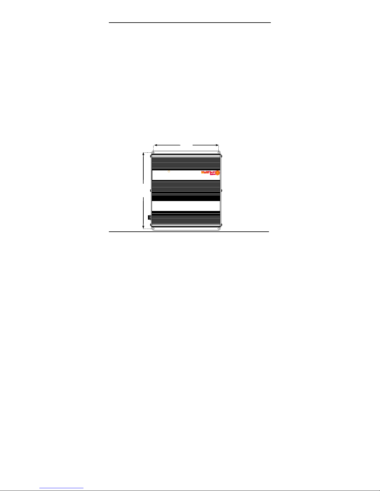
Mechanical Mounting
The FF120 & FF220 FaxFinder can be surface mounted with
screws spaced according to the dimensions shown. The FF420
& FF820 are normally table-top units but can be rack-mounted.
5.3”
13.5 cm
R
Fax
Finder
V.34 F ax Se rver
6.2”
15.7 cm
MultiTech Systems, Inc. 3
Page 4

Getting Started FaxFinder Cabling Guide
We Supply
• A FaxFinder (FF-120/220/420/820) with factory-installed
software
• One power supply with power cord (builds of FF-120/220 for
outside North America have a 2-piece power connection),
• Common telephone cables (1 for each port; RJ-11 at both
ends)
• A product CD that contains: (a) a suite of software programs
for client PCs, (b) a system management software package
for the administrator’s PC, and (c) additional documentation
for both administrators and client/users
• A set of four self-adhesive rubber feet (FF-120/220 only)
• Rack-mounting fasteners (FF-420/820 only)
• This printed Cabling Guide
You Supply
• A nearby AC power outlet
• A connection to your Ethernet LAN
• Telephony connections (to match number of ports on unit)
either - common subscriber (POTS) phone line jack(s)
or - PBX station port(s) or - both
• An admin PC (with web browser) to configure the FaxFinder
• Client PCs (Windows NT/2000/XP) with email and printing
applications and a PDF viewer (a TIFF viewer is provided).
Network clients receive faxes in their email inboxes as
4 MultiTech Systems, Inc.
Page 5

FaxFinder Cabling Guide Getting Started
graphic file attachments. They will send faxes by printing to
the FaxFinder server from application programs.
FaxFinder Operation
The FaxFinder Fax Servers provides two-way fax service to PC
client users on an Ethernet network.
Fax Sending
For outgoing faxing, users send faxes by using the Print
command of any application program and selecting the
FaxFinder as the target Printer.
Fax Receiving: Automated vs. Manual Routing
For incoming fax service, the FaxFinder converts the incoming
faxes into graphic files (PDF or TIF) that are sent as email
attachments to fax recipients on the ethernet network. These
emails may then either go directly to the recipient (Automated
Routing Mode) or to an attendant who will forward them to their
ultimate recipients (Manual Routing Mode).
To use Automated Routing Mode, the FaxFinder must operate
in conjunction with a PBX and the PBX must be able to route
many incoming DID fax numbers to a group of station ports as
DTMF digits. On the Multi-Tech website (look up “FaxFinder”
under Documents and see Configuration Guides) we have a list
of certified PBX configuration guides for FaxFinders. If you
MultiTech Systems, Inc. 5
Page 6

Application Considerations FaxFinder Cabling Guide
believe that your PBX has the necessary DID routing capability
but your PBX is not listed, contact Multi-Tech Technical Support
(see page 2). In Automated Routing Mode, the line ports on the
FaxFinder will be connected to the appropriate station ports on
your PBX.
With Manual Routing, each phone line connected to the
FaxFinder can have an email address assigned to it. In this case
the POTS lines will be connected to the line ports on the
FaxFinder.
6 MultiTech Systems, Inc.
Page 7

FaxFinder Cabling Guide Application Considerations
MultiTech Systems, Inc. 7
Page 8

Quick Hookup FaxFinder Cabling Guide
Quick Hookup for FF-120/220
FaxFinder FF-120/220 Hookup
Cabling to computer running
Cabling to telco POTS lines
or PBX station ports.
terminal software.
For debugging purposes only.
Connector at FaxFinder: RJ-45.
Connector at computer: DB-9.
Power Cable
Receptacle
LINE 1
Line 2 appears
on FF220 only.
LINE 2 LAN 1
Cabling to your IP network.
RJ-45 connector.
CONSOLE
RESET
Reset
Switch
8 MultiTech Systems, Inc.
Page 9

FaxFinder Cabling Guide Quick Hookup
Quick Hookup for FF-420/820
MultiTech Systems, Inc. 9
Page 10

Quick Hookup FaxFinder Cabling Guide
Earth Grounding for FF-420/820
Product
Ground
FF-420/820
Unit
Grounding connectors
must be secured
product ground screw
and earth ground screw.
Screw
permanently to
Ground Wire:
Size 18AWG
or thicker
Earth Ground Screw:
Connected to
Permanent Earth Ground
of Building’s
Electrical System
GND
10 MultiTech Systems, Inc.
Page 11

FaxFinder Cabling Guide Cabling Instructions
Power
Cable
Cabling Process
Summary: Place the FaxFinder in a convenient location, and
then connect it to your AC power outlet and Ethernet.
1. Connect FaxFinder to AC Outlet.
A. FF-120/220 Power. Plug the DC power transformer into
a power outlet or power strip. Secure the other end to
the Power Receptacle on your FaxFinder. Secure the
power cord to the connector with the lock nut. (Builds of
FF-120/220 for outside North America have a 2-piece
power connection.)
Caution: Use only the DC power transformer supplied
with the FaxFinder. Use of any other
transformer voids the warranty and can
damage the FaxFinder.
LINE 1
LINE 2 LAN 1
CONSOLE
FF-120/220
Receptacle
RESET
Lock Nut
MultiTech Systems, Inc. 11
Page 12

Cabling Instructions FaxFinder Cabling Guide
B. FF-420/820 Power. Connect the power cable between
the unit and a power outlet.
312 4
ETHERNET
87
5
6
COMMAND
FF-420/820
12 MultiTech Systems, Inc.
Page 13

FaxFinder Cabling Guide Cabling Instructions
2.Verify powering.
Status LED
FF-120/220
Power
Power
LED
Status
LAN 1
CF
LNK 100
Line 1
TDRDTR
Line 2
TDRDTR
CD
CD
Status LED
R
Power
Status
Power LED
After power is applied, the Power LED comes on immediately
but there is a 4-second delay before the Status LED comes on.
In normal operation, the Status LED will be flashing.
When you apply power, the FaxFinder performs a diagnostic
self-test. The Status indicator flashes when the test is complete
and the unit is ready. If this does not happen, check that the
power supply is solidly connected and that the AC outlet is live.
MultiTech Systems, Inc. 13
Ethernet
Modem 1
TDRDCD
Modem 2
TDRDCD
LNK IOO
Modem 3
TDRDCD
TD
Modem 4
Modem 5
Modem 6
Modem 7
RD CD
RD CD
TD
TD
Modem 8
RD CD
RD CD
RD CD
TD
TD
FF-420/820
Page 14

Cabling Instructions FaxFinder Cabling Guide
3. Connect FaxFinder to Ethernet Network.
Plug one end of your RJ45 ethernet cable into the FaxFinder’s
ethernet jack and the other end into your network ethernet hub.
This ethernet cable is not included with your FaxFinder unit.
Ethernet
Receptacle
FF-120/220
LINE 2
LINE 1
LAN 1
CONSOLE
RESET
312 4
ETHERNET
5
87
6
COMMAND
FF-420/820
Caution:
Before connecting to the Ethernet Network, make sure
that the network to which you are connecting the FaxFinder is not
a 192.168.2.x subnet. Because the FaxFinder’s factory default IP
address is 192.168.2.1, connecting it to a network that has a
different device at that same IP address would cause data
interference.
If it is a 192.168.2.x subnet, connect from the Administrative PC
to the FaxFinder using an RJ45 crossover cable until the
FaxFinder’s IP address has been configured. Thereafter, connect
the FaxFinder into the network with an ordinary RJ45 cable.
14 MultiTech Systems, Inc.
Page 15

FaxFinder Cabling Guide Cabling Instructions
4. Connect to Telephony Service
The FaxFinder’s fax modems can either be connected to a PBX
(for use in Automated Routing Mode) or to a POTS line
(for use in Manual Routing Mode).
Connection for
Automated Routing Mode
Plug one end of the phone
cable into the FaxFinder’s
LINE jack and the other
into an available Station
Port on the PBX.
Connection for
Manual Routing Mode
Plug one end of the phone
cable into the FaxFinder’s
LINE jack and the other end
into your standard telephone
receptacle.
One RJ11-to-RJ11 cable is included for each port of your
FaxFinder (1 for FF120, 2 for FF220; 4 for FF420; 8 for FF820).
Automated Routing Mode
ETHERNET
312 4
87
5
6
COMMAND
Manual
Routing
Mode
LINE 1
RESET
CONSOLE
LINE 2 LAN 1
MultiTech Systems, Inc. 15
Page 16

Patents
This device is covered by one or more of the following patents: 6,031,867;
6,012,113; 6,009,082; 5,905,794; 5,864,560; 5,815,567; 5,815,503; 5,812,534;
5,809,068; 5,790,532; 5,764,628; 5,764,627; 5,754,589; D394,250; 5,724,356;
5,673,268; 5,673,257; 5,644,594; 5,628,030; 5,619,508; 5,617,423; 5,600,649;
5,592,586; 5,577,041; 5,574,725; D374,222; 5,559,793; 5,546,448; 5,546,395;
5,535,204; 5,500,859; 5,471,470; 5,463,616; 5,453,986; 5,452,289; 5,450,425;
D361,764; D355,658; D355,653; D353,598; D353,144; 5,355,365; 5,309,562;
5,301,274. Other patents pending.
82100261L
 Loading...