

Page 1
®
Conduit
MTCAP-L4E1 User Guide for Europe
AP
Page 2

CONDUIT AP MTCAP USER GUIDE FOR EUROPE
Conduit AP MTCAP User Guide for Europe
Models: MTCAP-L4E1-868-001L, MTCAP-868-001L, MTCAP-L4E1-868-001A, MTCAP-868-001A
Part Number: S000723, Version 1.0
Copyright
This publication may not be reproduced, in whole or in part, without the specific and express prior written permission signed by an executive officer of
Multi-Tech Systems, Inc. All rights reserved. Copyright © 2019 by Multi-Tech Systems, Inc.
Multi-Tech Systems, Inc. makes no representations or warranties, whether express, implied or by estoppels, with respect to the content, information,
material and recommendations herein and specifically disclaims any implied warranties of merchantability, fitness for any particular purpose and noninfringement.
Multi-Tech Systems, Inc. reserves the right to revise this publication and to make changes from time to time in the content hereof without obligation of
Multi-Tech Systems, Inc. to notify any person or organization of such revisions or changes.
Trademarks and Registered Trademarks
MultiTech, the MultiTech logo, DeviceHQ, xDot, and Conduit are registered trademarks and mPower and mDot are trademarks of Multi-Tech Systems, Inc.
All other products and technologies are the trademarks or registered trademarks of their respective holders.
Legal Notices
The MultiTech products are not designed, manufactured or intended for use, and should not be used, or sold or re-sold for use, in connection with
applications requiring fail-safe performance or in applications where the failure of the products would reasonably be expected to result in personal injury or
death, significant property damage, or serious physical or environmental damage. Examples of such use include life support machines or other life
preserving medical devices or systems, air traffic control or aircraft navigation or communications systems, control equipment for nuclear facilities, or
missile, nuclear, biological or chemical weapons or other military applications (“Restricted Applications”). Use of the products in such Restricted
Applications is at the user’s sole risk and liability.
MULTITECH DOES NOT WARRANT THAT THE TRANSMISSION OF DATA BY A PRODUCT OVER A CELLULAR COMMUNICATIONS NETWORK WILL BE
UNINTERRUPTED, TIMELY, SECURE OR ERROR FREE, NOR DOES MULTITECH WARRANT ANY CONNECTION OR ACCESSIBILITY TO ANY CELLULAR
COMMUNICATIONS NETWORK. MULTITECH WILL HAVE NO LIABILITY FOR ANY LOSSES, DAMAGES, OBLIGATIONS, PENALTIES, DEFICIENCIES, LIABILITIES,
COSTS OR EXPENSES (INCLUDING WITHOUT LIMITATION REASONABLE ATTORNEYS FEES) RELATED TO TEMPORARY INABILITY TO ACCESS A CELLULAR
COMMUNICATIONS NETWORK USING THE PRODUCTS.
The MultiTech products and the final application of the MultiTech products should be thoroughly tested to ensure the functionality of the MultiTech
products as used in the final application. The designer, manufacturer and reseller has the sole responsibility of ensuring that any end user product into
which the MultiTech product is integrated operates as intended and meets its requirements or the requirements of its direct or indirect customers.
MultiTech has no responsibility whatsoever for the integration, configuration, testing, validation, verification, installation, upgrade, support or maintenance
of such end user product, or for any liabilities, damages, costs or expenses associated therewith, except to the extent agreed upon in a signed written
document. To the extent MultiTech provides any comments or suggested changes related to the application of its products, such comments or suggested
changes is performed only as a courtesy and without any representation or warranty whatsoever.
Contacting MultiTech
Knowledge Base
The Knowledge Base provides immediate access to support information and resolutions for all MultiTech products. Visit http://www.multitech.com/kb.go.
Support Portal
To create an account and submit a support case directly to our technical support team, visit: https://support.multitech.com.
Support
Business Hours: M-F, 8am to 5pm CT
Country By Email By Phone
Europe, Middle East, Africa: support@multitech.co.uk +(44) 118 959 7774
U.S., Canada, all others: support@multitech.com (800) 972-2439 or (763) 717-5863
Warranty
To read the warranty statement for your product, visit www.multitech.com/warranty.go. For other warranty options, visit www.multitech.com/es.go.
World Headquarters
Multi-Tech Systems, Inc.
2205 Woodale Drive, Mounds View, MN 55112
Phone: (800) 328-9717 or (763) 785-3500
Fax (763) 785-9874
2 Conduit®AP MTCAP-L4E1 User Guide for Europe
Page 3

CONTENTS
Contents
Chapter 1 – Product Overview ................................................................................................................................. 5
Overview ....................................................................................................................................................................... 5
Product Build Options ................................................................................................................................................... 5
Package Contents.......................................................................................................................................................... 5
Documentation Overview ............................................................................................................................................. 5
Related Documentation .............................................................................................................................................. 6
Chapter 2 – Specifications and Hardware Information ............................................................................................. 7
Dimensions.................................................................................................................................................................... 7
MTCAP Specifications.................................................................................................................................................... 8
LoRa Transmission Output Power................................................................................................................................. 8
868 Models ................................................................................................................................................................. 8
Connectors and LEDs..................................................................................................................................................... 9
Resetting the Device ................................................................................................................................................. 10
Power Measurements................................................................................................................................................. 10
MTCAP-L4E1-868-001L.............................................................................................................................................. 10
MTCAP-868-001L ...................................................................................................................................................... 12
Chapter 3 – Safety Information .............................................................................................................................. 13
Power Supply Caution ................................................................................................................................................. 13
Ethernet Ports ............................................................................................................................................................. 13
Ports Ethernet ........................................................................................................................................................... 13
General Safety............................................................................................................................................................. 13
Handling Precautions .................................................................................................................................................. 13
Radio Frequency (RF) Safety ....................................................................................................................................... 13
Sécurité relative aux appareils à radiofréquence (RF).............................................................................................. 14
Interference with Pacemakers and Other Medical Devices ...................................................................................... 14
Potential interference............................................................................................................................................... 14
Precautions for pacemaker wearers ........................................................................................................................ 14
Device Maintenance ................................................................................................................................................... 15
UL Notice .................................................................................................................................................................... 15
Spécifications UL ...................................................................................................................................................... 15
User Responsibility...................................................................................................................................................... 16
Chapter 4 – Labels.................................................................................................................................................. 17
Example Labels............................................................................................................................................................ 17
Chapter 5 – Setting Up Hardware........................................................................................................................... 18
Installing a SIM Card ................................................................................................................................................... 18
Removing a SIM Card................................................................................................................................................ 18
Cabling the Device....................................................................................................................................................... 18
Conduit®AP MTCAP-L4E1 User Guide for Europe 3
Page 4

CONTENTS
Chapter 6 – Getting Started with mLinux Models................................................................................................... 19
Accessing the Terminal Interface................................................................................................................................ 19
Setting Time Zone, Time, and Date............................................................................................................................. 19
Setting the Custom IP Address, Network Information, and Ethernet Internet Access .............................................. 20
Configuring the Cellular Connection........................................................................................................................... 20
Starting Cellular Connection on Boot ......................................................................................................................... 21
Configuring the LoRa Network Server for mLinux ...................................................................................................... 22
Additional LoRa and mLinux Information ................................................................................................................... 23
Chapter 7 – Getting Started with AEP Models ........................................................................................................ 24
Logging in to AEP......................................................................................................................................................... 24
Setting the Password .................................................................................................................................................. 24
Setting Date and Time................................................................................................................................................. 24
Configuring PPP........................................................................................................................................................... 24
Setting Up PPP Authentication ................................................................................................................................... 25
Entering IP Address and Network Information........................................................................................................... 25
Configuring Access ...................................................................................................................................................... 25
Finishing Configuration ............................................................................................................................................... 26
Using DeviceHQ for Device Management................................................................................................................... 26
Chapter 8 – Mounting the Device........................................................................................................................... 27
Mounting the Device................................................................................................................................................... 27
You will need............................................................................................................................................................. 27
Determining Location for the MTCAP....................................................................................................................... 27
Mounting the MTCAP ............................................................................................................................................... 28
Chapter 9 – Regulatory and Environmental............................................................................................................ 30
EMC, Safety, and Radio Equipment Directive (RED) Compliance .............................................................................. 30
Waste Electrical and Electronic Equipment Statement .............................................................................................. 30
WEEE Directive.......................................................................................................................................................... 30
Instructions for Disposal of WEEE by Users in the European Union ........................................................................ 30
REACH Statement ....................................................................................................................................................... 31
Registration of Substances........................................................................................................................................ 31
Restriction of the Use of Hazardous Substances (RoHS) ............................................................................................ 31
Information on HS/TS Substances According to Chinese Standards ......................................................................... 32
Information on HS/TS Substances According to Chinese Standards (in Chinese) ...................................................... 33
Index...................................................................................................................................................................... 34
4 Conduit®AP MTCAP-L4E1 User Guide for Europe
Page 5

PRODUCT OVERVIEW
Chapter 1 – Product Overview
Overview
Conduit AP (MTCAP) connects thousands of IoT assets to the cloud using the LoRaWAN®protocol. It expands LoRa
network coverage to difficult to reach areas and is capable of packet forwarding user data between LoRa end
points and a centrally located network server on the cloud, in a data center, or a public network.
Note: Check for an updated version of this document at https://www.multitech.com/brands/multiconnect-
conduit-ap/.
Product Build Options
Product Description
MTCAP-L4E1-868-001L Conduit AP with LTE and LoRa 868 MHz using mLinux
MTCAP-868-001L Conduit AP with LoRa 868 MHz using mLinux
MTCAP-L4E1-868-001A Conduit AP with LTE and LoRa 868 MHz using AEP
MTCAP-868-001A Conduit AP with LoRa 868 MHz using AEP
Note: The complete product code may end in .Rx, where R is revision and x is the revision number. For
example, MTCAP-L4E1-868-001L-R1.
Package Contents
Your device ships with the following:
1 – MTCAP
1 – 5 Volt, 2.5 Amp power supply
1 – RJ45 Ethernet cable
1 – Quick Start
Important: Contact MultiTech Systems if a replacement power supply is needed. Using a different power
supply may damage the device and voids the warranty.
Documentation Overview
The following documents are available at http://www.multitech.com/brands/multiconnect-conduit-ap. Select your
model to find the documents specific for that device.
Document Description
Conduit AP MTCAP User Guide for Europe This document. Hardware, regulatory, and getting started
information.
Conduit AP MTCAP for mLinux Quick Start Steps for getting started with mLinux models. Ships with
the device and is available online.
Conduit®AP MTCAP-L4E1 User Guide for Europe 5
Page 6

PRODUCT OVERVIEW
Document Description
Conduit AP MTCAP for AEP Quick Start Steps for getting started with AEP models. Ships with
device and is available online.
Telit LE910 AT Commands Reference Guide For L4E1 devices, lists AT Commands and parameters used
to communicate with your device. 80502ST10950A
Related Documentation
This manual provides the basics for getting started with mLinux or AEP. For addition information, visit our
developer site at http://multitech.net and select Software > mLinux.
6 Conduit®AP MTCAP-L4E1 User Guide for Europe
Page 7
SPECIFICATIONS AND HARDWARE INFORMATION
Chapter 2 – Specifications and Hardware Information
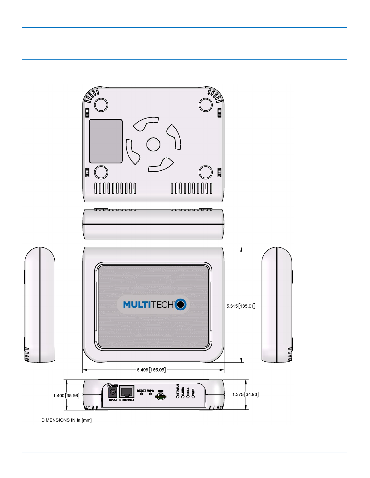
Dimensions
Conduit®AP MTCAP-L4E1 User Guide for Europe 7
Page 8

SPECIFICATIONS AND HARDWARE INFORMATION
MTCAP Specifications
Category Description
General
Standards LoRaWAN 1.0.2 specifications
LTE FDD Cat 4, 3GPP release compliant (-L4E1 models only)
HSPA+ with GPRS fallback (-L4E1 models only)
RAM 256MB
Flash 256MB
Radio Frequency
ISM Band 868 MHz ISM band for Europe
4G/LTE 4G: B1, B3, B7, B8, B20, B28A (-L4E1 models only)
3G 3G: B1, B3, B8 (-L4E1 models only)
2G 2G: B3, B8 (-L4E1 models only)
Physical Description
Weight 1.36 kg
Dimensions Refer to Mechanical Drawings for Dimensions.
Chassis Type PC-ABS
Environment
Operating Temperature10° C to +70° C
Storage Temperature -40° C to +85° C
Humidity 20%-90% RH, non-condensing
Power Requirements
Operating Voltage 5Vdc, 1.4A
Certifications and Compliance
EMC and Radio
Compliance
Safety Compliance IEC 60950-1 2nd ED AM1 + AM2
1
UL listed at 40° C, limited by AC power supply. Product has been tested to +70° C excluding power supply.
CE Mark, RED (EU)
LoRa Transmission Output Power
868 Models
Max output 25 dBm
8 Conduit®AP MTCAP-L4E1 User Guide for Europe
Page 9
SPECIFICATIONS AND HARDWARE INFORMATION
Power Frequency On Power-up (dBm) 18 Hours After
Power-up (dBm)
27 869.525 MHz 24.18 25 125 kHz
27 869.525 MHz 24.18 24.83 250 kHz
Bandwidth
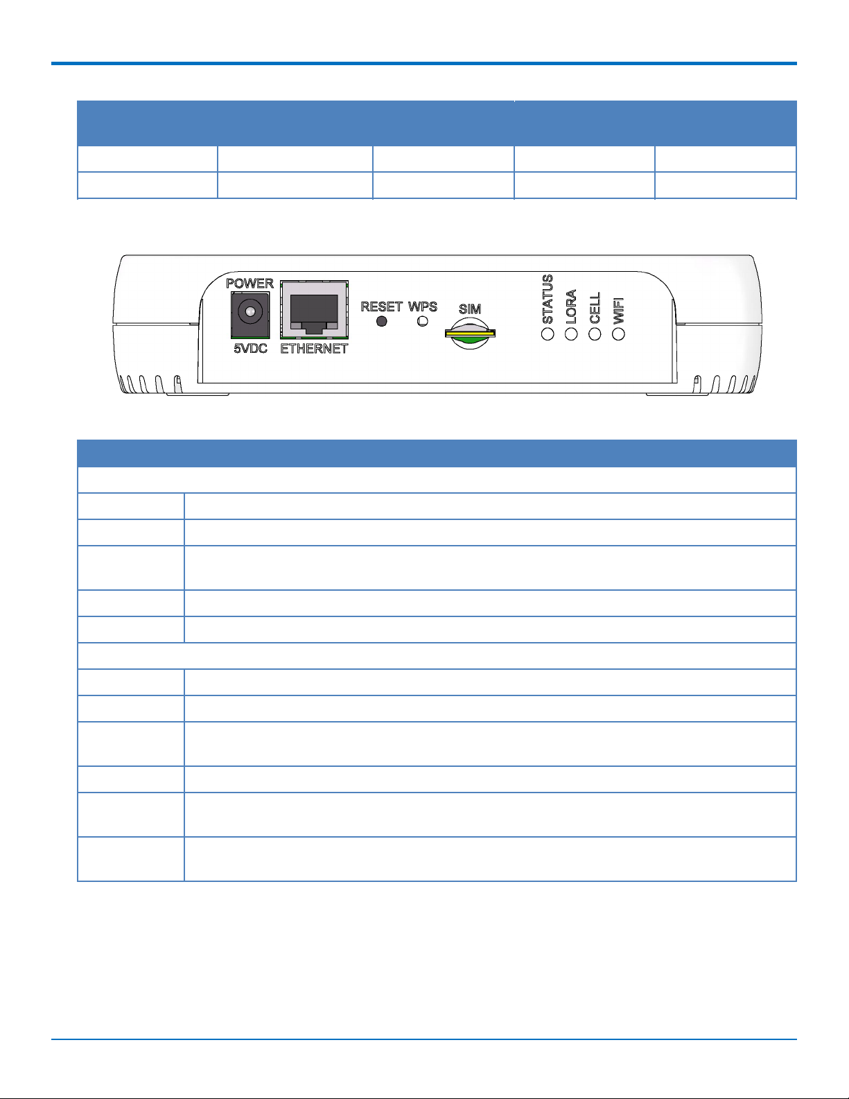
Connectors and LEDs
Note: Some features are available only on select models. The above image shows the model with all features.
For models that don't have a cellular radio, the chassis will not have a SIM slot.
Item Description
Connectors
Power 5 Volt power jack.
Ethernet RJ45 Ethernet jack.
Reset Reset button. Reboots device or restores factory defaults. Refer to Resetting the Device for
details.
WPS Reserved for future use.
SIM Cellular models only. SIM slot. Refer to Installing SIM Card for details.
LEDs
STATUS Blinks when operating system is fully loaded.
LORA Lights when LoRa software is active.
CELL Cellular models only. Lights when there is power to the radio. Blinks when the SIM is registered
with the carrier.
WIFI Reserved for future use.
Ethernet Link Left LED on the Ethernet connector. Blinks when data is sent or received on the Ethernet link.
Steady light when there is a valid Ethernet connection.
Ethernet Speed Right LED on the Ethernet connector. Lit when the Ethernet is linked at 100 Mbps. If not lit, the
Ethernet is linked at 10 Mbps.
Conduit®AP MTCAP-L4E1 User Guide for Europe 9
Page 10

SPECIFICATIONS AND HARDWARE INFORMATION
Resetting the Device
You need:
A pin, paperclip, or similar thin object that can fit into the reset hole
To reset the device:
1. Find the hole labeled RESET. The reset button is recessed into the case.
2. Use the pin to press and release the RESET button as follows:
Reset options:
To reboot, press RESET for less than 3 seconds.
To reboot and restore user-defined defaults (if previously set), press RESET for 3 to 29
seconds.
To reboot, restore factory settings, and erase user-defined defaults, press RESET for 30
seconds or longer.
The device restarts in commissioning mode. The system automatically removes all user
accounts.
Enter a new username and password to create your new administrative account. (Refer to
User Accounts in the appropriate software guide for details on username and password
requirements.)
Note: The device reboots when restoring settings.
Power Measurements
MTCAP-L4E1-868-001L
Note:
Multi-Tech Systems, Inc. recommends that you incorporate a 10% buffer into the power source
when determining product load.
Maximum Power: The continuous current during maximum data rate with the radio transmitter at
maximum power.
Tx Pulse: The average peak current during a GSM850 transmission burst period or HSDPA/LTE
connection. The transmission burst duration for GSM850 can vary, depending on what transmission
scheme is being deployed (GPRS Class 8, Class 10, GSM, etc.).
Inrush Charge: The total inrush charge at power on.
Radio Protocol Sleep Mode
Current (If
Applicable)
Cellular
Call Box
Connectio
n, No Data
Average
Measured
Current at
Maximum
Power
TX Pulse (AVG)
Amplitude
Current for
GSM850 or
Peak Current
for HSDPA/LTE
Total Inrush
Charge
Measured in
Millicoulomb
Total
Inrush
Charge
Duration
During
Power Up
5.0 Volts
EGSM 900 MHz NA 222 mA 760 mA 2.06 Amps 1.40 mC 1.63 mS
WCDMA NA 225 mA 1.18 Amps 1.29 Amps 1.40 mC 1.63 mS
10 Conduit®AP MTCAP-L4E1 User Guide for Europe
Page 11

SPECIFICATIONS AND HARDWARE INFORMATION
Radio Protocol Sleep Mode
Current (If
Applicable)
Cellular
Call Box
Connectio
n, No Data
Average
Measured
Current at
Maximum
Power
TX Pulse (AVG)
Amplitude
Current for
GSM850 or
Peak Current
for HSDPA/LTE
Total Inrush
Charge
Measured in
Millicoulomb
Total
Inrush
Charge
Duration
During
Power Up
LTE NA 225 mA 1.19 Amps 1.30 Amps 1.40 mC 1.63 mS
Conduit®AP MTCAP-L4E1 User Guide for Europe 11
Page 12

SPECIFICATIONS AND HARDWARE INFORMATION
MTCAP-868-001L
Note:
Multi-Tech Systems, Inc. recommends that you incorporate a 10% buffer into the power source
when determining product load.
Maximum Power: MTCAP LoRa connection to MTXDOT running TXP =20 and at+txdr=2. The
MTXDOT was initialized to send packets by joining MTCAP and rapidly sending packet to the MTCAP.
Tx Pulse: The average peak current.
Inrush Charge: The total inrush charge at power on.
Average Measured Current at
Maximum Power
5.0 Volts
432 mA 516 mA 1.28 mC
TX Pulse Peak Current for no radio
model
Total Inrush Charge Measured in
Millicoulomb
12 Conduit®AP MTCAP-L4E1 User Guide for Europe
Page 13

Chapter 3 – Safety Information
Power Supply Caution
CAUTION: Do not replace the power supply with one designed for another product; doing so can damage the
modem and void your warranty. Adapter shall be installed near the equipment and shall be easily accessible.
CAUTION: Pour garantir une protection continue contre les risques d'incendie, remplacez les fusibles
uniquement par des fusibles du même type et du même calibre. L'adaptateur doit être installé à proximité de
l'appareil et doit ê tre facilement accessible.
Ethernet Ports
CAUTION: Ethernet ports and command ports are not designed to be connected to a public telecommunication
network or used outside the building or campus.
Ports Ethernet
CAUTION: Les ports Ethernet et de commande ne sont pas conçus pour être raccordés à un r éseau de
télécommunications public ou utilisé à l'extérieur du bâtiment.
SAFETY INFORMATION
General Safety
The device is designed for and intended to be used in fixed and mobile applications. Fixed means the device is
physically secured at one location and cannot be easily moved to another location. Mobile means the device is
used in other than fixed locations.
CAUTION: Maintain a separation distance of at least 20 cm (8 inches) between the transmitter’s antenna and
the body of the user or nearby persons. The device is not designed for or intended to be used in portable
applications within 20 cm (8 inches) of the user’s body.
Attention: Maintenir une distance d'au moins 20 cm (8 po) entre l'antenne du récepteur et le corps de
l'utilisateur ou à proximité de personnes. Le modem n'est pas conçu pour, ou destinés à être utilisés dans les
applications portables, moins de 20 cm du corps de l'utilisateur.
Handling Precautions
To avoid damage due to the accumulation of static charge, use proper precautions when handling any cellular
device. Although input protection circuitry has been incorporated into the devices to minimize the effect of static
build-up, use proper precautions to avoid exposure to electronic discharge during handling and mounting the
device.
Radio Frequency (RF) Safety
Due to the possibility of radio frequency (RF) interference, it is important that you follow any special regulations
regarding the use of radio equipment. Follow the safety advice given below.
Operating your device close to other electronic equipment may cause interference if the equipment is
inadequately protected. Observe any warning signs and manufacturers’ recommendations.
Different industries and businesses restrict the use of cellular devices. Respect restrictions on the use of
radio equipment in fuel depots, chemical plants, or where blasting operations are in process. Follow
restrictions for any environment where you operate the device.
Conduit®AP MTCAP-L4E1 User Guide for Europe 13
Page 14

SAFETY INFORMATION
Do not place the antenna outdoors.
Switch OFF your wireless device when in an aircraft. Using portable electronic devices in an aircraft may
endanger aircraft operation, disrupt the cellular network, and is illegal. Failing to observe this restriction
may lead to suspension or denial of cellular services to the offender, legal action, or both.
Switch OFF your wireless device when around gasoline or diesel-fuel pumps and before filling your vehicle
with fuel.
Switch OFF your wireless device in hospitals and any other place where medical equipment may be in use.
Sécurité relative aux appareils à radiofréquence (RF)
À cause du risque d'interférences de radiofréquence (RF), il est important de respecter toutes les réglementations
spéciales relatives aux équipements radio. Suivez les conseils de sécurité ci-dessous.
Utiliser l'appareil à proximité d'autres équipements électroniques peut causer des interférences si les
équipements ne sont pas bien protégés. Respectez tous les panneaux d'avertissement et les
recommandations du fabricant.
Certains secteurs industriels et certaines entreprises limitent l'utilisation des appareils cellulaires. Respectez
ces restrictions relatives aux équipements radio dans les dépôts de carburant, dans les usines de produits
chimiques, ou dans les zones où des dynamitages sont en cours. Suivez les restrictions relatives à chaque
type d'environnement où vous utiliserez l'appareil.
Ne placez pas l'antenne en extérieur.
Éteignez votre appareil sans fil dans les avions. L'utilisation d'appareils électroniques portables en avion est
illégale: elle peut fortement perturber le fonctionnement de l'appareil et désactiver le réseau cellulaire. S'il
ne respecte pas cette consigne, le responsable peut voir son accès aux services cellulaires suspendu ou
interdit, peut être poursuivi en justice, ou les deux.
Éteignez votre appareil sans fil à proximité des pompes à essence ou de diesel avant de remplir le r éservoir
de votre véhicule de carburant.
Éteignez votre appareil sans fil dans les hôpitaux ou dans toutes les zones où des appareils médicaux sont
susceptibles d'être utilisés.
Interference with Pacemakers and Other Medical Devices
Potential interference
Radio frequency energy (RF) from cellular devices can interact with some electronic devices. This is
electromagnetic interference (EMI). The FDA helped develop a detailed test method to measure EMI of implanted
cardiac pacemakers and defibrillators from cellular devices. This test method is part of the Association for the
Advancement of Medical Instrumentation (AAMI) standard. This standard allows manufacturers to ensure that
cardiac pacemakers and defibrillators are safe from cellular device EMI.
The FDA continues to monitor cellular devices for interactions with other medical devices. If harmful interference
occurs, the FDA will assess the interference and work to resolve the problem.
Precautions for pacemaker wearers
If EMI occurs, it could affect a pacemaker in one of three ways:
Stop the pacemaker from delivering the stimulating pulses that regulate the heart's rhythm.
Cause the pacemaker to deliver the pulses irregularly.
14 Conduit®AP MTCAP-L4E1 User Guide for Europe
Page 15

SAFETY INFORMATION
Cause the pacemaker to ignore the heart's own rhythm and deliver pulses at a fixed rate.
Based on current research, cellular devices do not pose a significant health problem for most pacemaker wearers.
However, people with pacemakers may want to take simple precautions to be sure that their device doesn't cause
a problem.
Keep the device on the opposite side of the body from the pacemaker to add extra distance between the
pacemaker and the device.
Avoid placing a turned-on device next to the pacemaker (for example, don’t carry the device in a shirt or
jacket pocket directly over the pacemaker).
Device Maintenance
Do not attempt to disassemble the device. There are no user serviceable parts inside.
When maintaining your device:
Do not misuse the device. Follow instructions on proper operation and only use as intended. Misuse could
make the device inoperable, damage the device and/or other equipment, or harm users.
Do not apply excessive pressure or place unnecessary weight on the device. This could result in damage to
the device or harm to users.
Do not use this device in explosive or hazardous environments unless the model is specifically approved for
such use. The device may cause sparks. Sparks in explosive areas could cause explosion or fire and may
result in property damage, severe injury, and/or death.
Do not expose your device to any extreme environment where the temperature or humidity is high. Such
exposure could result in damage to the device or fire. Refer to the device specifications regarding
recommended operating temperature and humidity.
Do not expose the device to water, rain, or spilled beverages. Unless the device is IP67 rated, it is not
waterproof. Exposure to liquids could result in damage to the device.
Do not place the device alongside computer discs, credit or travel cards, or other magnetic media. The
information contained on discs or cards may be affected by the device.
Using accessories, such as antennas, that MultiTech has not authorized or that are not compliant with
MultiTech's accessory specifications may invalidate the warranty.
If the device is not working properly, contact MultiTech Technical Support.
UL Notice
UL Listed at 40° C, limited by power supply. UL Certification does not apply or extend to an ambient above 40° C
and has not been evaluated by UL for ambient greater than 40° C. “UL has evaluated this device for use in ordinary
locations only. Installation in a vehicle or other outdoor locations has not been evaluated by UL. UL Certification
does not apply or extend to use in vehicles or outdoor applications or in ambient above 40° C.”
Spécifications UL
Listé UL à 40° C, limité par l'alimentation. La certification UL ne s'applique pas ou ne s'étend pas à des
températures dépassant 40° C, et le produit n'a pas été évalué par UL pour une température ambiante dépassant
40° C. « UL a évalué cet appareil pour une utilisation en zone ordinaire uniquement. Le produit n'a pas été évalué
par UL pour une installation dans un véhicule ou en extérieur. La certification UL ne s'applique pas ou ne s'étend
pas aux applications dans un véhicule, en extérieur ou en présence d'une température ambiante supérieure à 40°
C ».
Conduit®AP MTCAP-L4E1 User Guide for Europe 15
Page 16

SAFETY INFORMATION
User Responsibility
Respect all local regulations for operating your wireless device. Use the security features to block unauthorized use
and theft.
16 Conduit®AP MTCAP-L4E1 User Guide for Europe
Page 17

Chapter 4 – Labels
Example Labels
Note: Actual labels vary depending on the regulatory approval markings and content.
This device complies with part 15 of the FCC Rules. Operation is subject to the following two conditions: (1) This
device may not cause harmful interference, and (2) this device must accept any interference received, including
interference that may cause undesired operation.
The label shown is not the actual size.
1 - MultiTech Model Identification.
2 - MultiTech Ordering Part Number.
3 - IMEI Number
4 - Device Node Number
5 - UUID
Example 868 Models Device Label
LABELS
Conduit®AP MTCAP-L4E1 User Guide for Europe 17
Page 18

SETTING UP HARDWARE
Chapter 5 – Setting Up Hardware
Installing a SIM Card
If your device has a SIM slot, you'll need a micro SIM card from your network provider.
To install the SIM card:
With the contact side facing down, align the notched edge as shown on the following image and slide the
SIM card completely into the SIM holder.
Removing a SIM Card
To remove the SIM card, push the SIM card in. The device ejects the SIM card.
Cabling the Device
To cable the device:
1. Connect the Ethernet cable to the Ethernet port on the device and to your computer.
2. Connect the power supply to the MTCAP's power jack and plug it into an electrical outlet. When the
operating system is fully loaded, the STATUS LED blinks.
Once your device is cabled, follow the Getting Started chapter for your device:
For models ending with -001L , go to Getting Started with mLinux
For models ending with -001A, go to Getting Started with AEP
18 Conduit®AP MTCAP-L4E1 User Guide for Europe
Page 19

GETTING STARTED WITH MLINUX MODELS
Chapter 6 – Getting Started with mLinux Models
Accessing the Terminal Interface
After connecting Ethernet and power, access the terminal interface:
1. On your PC, configure a static IP address for the network interface that is connected to the device within
the following range:
192.168.2.2 - 192.168.2.254
2. Open an SSH connection and log in.
Default IP address: (DHCP is disabled)
192.168.2.1
Default credentials for mLinux version 3: username:
root
and password:
root
Default credentials for mLinux version 4: username:
mtadm
and password:
root
Note: The above credentials do NOT have root privileges. As a result, many commands may not work unless
you use sudo (for super user permissions).
To use sudo, either execute :
sudo [command]
or start the root shell:
sudo -s
Then enter the mtadm password. The prompt changes to mtcap:/home/mtadm#
For tips on using sudo, go to http://www.multitech.net/developer/software/mlinux/using-mlinux/log-in-
as-an-admin-post-production/.
The following commands require sudo:
ln -sf /usr/share ...
hwclock
ifdown
ifup
mlinux-set-apn
pppd
killall
/etc/init.d/lora-packet-forwarder
Setting Time Zone, Time, and Date
To set the time zone, date, and time:
1. Create a symbolic link from the zone info file for your location to /etc/localtime:
Conduit®AP MTCAP-L4E1 User Guide for Europe 19
Page 20

GETTING STARTED WITH MLINUX MODELS
ln -fs /usr/share/zoneinfo/Europe/Zurich /etc/localtime
2. Update the date and time to the current time:
date "2016-12-11 14:58:01"
3. Update the hardware clock:
hwclock -u -w
Setting the Custom IP Address, Network Information, and Ethernet Internet Access
Network configuration is defined in /etc/network/interfaces.
1. To change the static IP, change the address and netmask fields in /etc/network/interfaces, (use vi or
nano).
2. To apply changes, either reboot the device or issue:
ifdown eth0 && ifup eth0
Note: You will lose your SSH session by doing this.
3. To enable DHCP with default settings, edit /etc/udhcpd.conf (using vi or nano) by entering, starting, and
ending IP addresses for DHCP range.
mlinux-dhcpd start
4. Issue this command to start DHCP:
mlinux-dhcpd start
Note: To stop or restart, issue:
mlinux-dhcpd stop
or
mlinux-dhcpd restart
5. To configure Internet access via the Ethernet port, modify /etc/network/interfaces as follows:
a. Add gateway 192.168.2.254 beneath the netmask line, where 192.168.2.254 is the IP address of
your network router.
b. To apply changes, either reboot the device or issue:
ifdown eth0 && ifup eth0
Note: You will lose your SSH session by doing this.
c. Test Internet access with ping 8.8.8.8.
Configuring the Cellular Connection
To establish a cellular data link, you must configure and initiate a PPP connection. Sample options, files, and chat
scripts are provided in the ppp peers directory /etc/ppp/peers. Anything specific to the network or connection
should be placed in one of these files. Global options should be placed in /etc/ppp/options.
1. Set up a cellular data connection.
20 Conduit®AP MTCAP-L4E1 User Guide for Europe
Page 21

GETTING STARTED WITH MLINUX MODELS
Set "APN" to the APN for your cellular provider. (Not necessary for
Verizon SIMs)
# mlinux-set-apn APN
# Before establishing PPP connection, modify the file, /etc/ppp/options
sudo -s
echo -e '+ipv6\nipv6cp-use-ipaddr' >>/etc/ppp/options
# Dial the connection (using /etc/ppp/peers/xxx# config)
# pppd call xxx#
(where xxx# is your radio, L4E1 for Europe)
2. Use the Linux route utility to verify ppp0 is up.
# route
Kernel IP routing table
Destination Gateway Genmask Flags MetricRef Use Iface
default 33.140.12.180.0.0.0 UG 0 0 0 ppp0
33.140.12.18* 255.255.255.255UH 0 0 0 ppp0
192.168.2.0 * 255.255.255.0 U 0 0 0 ethp0
The Linux ifconfig utility can be used to inspect the ppp0 interface details.
# ifconfig ppp0
ppp0 Link encap:Point-to-Point Protocol
inet addr:33.140.12.18 P-t-
P:33.140.12.18 Mask:255.255.255.255
UP POINTOPOINT RUNNING NOARP MULTICAST MTU:1500 Metric:1
RX packets:7 errors:0 dropped:0 overruns:0 frame:0
TX packets:8 errors:0 dropped:0 overruns:0 carrier:0
collisions:0 txqueuelen:3
RX bytes:106 (106.0 B) TX bytes:145 (145.0 B)
Additionally, you can view the pppd logs in /var/log/messages to see the modem dialing and assigned IP
address or errors if the connection was unsuccessful.
To Stop a PPP Connection
# send SIGTERM to pppd, which causes it to hang up and exit cleanly
# killall pppd
Starting Cellular Connection on Boot
Automatically starting pppd on boot requires (1) setting the peer file to use and (2) telling the system to run the
ppp init script on boot.
1. To see the available peers files (l4e1) to set the peer file, issue:
Conduit®AP MTCAP-L4E1 User Guide for Europe 21
Page 22

GETTING STARTED WITH MLINUX MODELS
ls /etc/ppp/peers
2. Edit /etc/ppp/ppp_on_boot (with vi or sudo) and change:
#PPPD call provider
to your desired provider (where xxx# is your radio, L4E1 for Europe.)
#PPPD call xxx#
3. Manually start the init script and check your Internet connection to test your change.
ppp_on_boot
# /etc/init.d/ppp start
4. To set init script to auto start, issue:
# update-rc.d ppp defaults
5. Restart and test your connection.
Stop Automatic Start Up
To stop ppp from automatically starting, issue:
# update-rc.d -f ppp remove
Configuring the LoRa Network Server for mLinux
Note: This section applies to LoRaWAN V1.5 devices only.
To configure the LoRa Network Server:
1. Log in to the console. Refer to http://www.multitech.net/developer/software/mlinux/getting-started-
with-conduit-mlinux/ if needed.
2. Issue these commands:
# cp /opt/lora/lora-network-server.conf.sample /var/config/lora/loranetwork-server.conf
3. Edit /var/config/lora/lora-network-server.conf and modify these settings as needed (use vi or nano).
Field LoRa-915 (NA, AU, AS, KR) LoRa-868 (EU, IN)
lora["frequencyBand"]: "915" "868"
lora["channelplan"]: "US915", "AU915", "AS923", or
"KR920"
lora["frequencySubBand"]: (integer. 1 to 8) Not applicable
lora["frequencyEU"]: Not Applicable default 869500000
"EU868" or "IN865"
range: [863500000 - 867500000] and
[869100000 - 869500000]
network["name"] Name of your LoRa network (string, 8-character minimum, case-sensitive).
network["passphrase"] Security passphrase for your LoRa network (string, 8-character minimum,
case-sensitive).
network["public"] Choose from 0: Private MTS, 1: Public LoRaWAN or 2: Private LoRaWAN,
Private Options use SyncWord 0×12 vs Public SyncWord 0×34.
network["joinDelay"]: Set to desired Join Delay, default 5 seconds
22 Conduit®AP MTCAP-L4E1 User Guide for Europe
Page 23

GETTING STARTED WITH MLINUX MODELS
4. Restart the network server.
# /etc/init.d/lora-network-server restart
5. Start mosquitto client.
# mosquitto_sub -t lora/+/+ -v
For advanced LoRa settings, go to http://www.multitech.net/developer/software/lora/conduit-mlinux-lora-
communication/conduit-mlinux-advance-lora-configuration/.
Additional LoRa and mLinux Information
For additional information, including how to configure LoRa devices to communicate with your gateway, visit
http://www.multitech.net.
For an introduction to Lora, go to : http://www.multitech.net/developer/software/lora/introduction-to-lora/
For help using mLinux, go to: http://www.multitech.net/developer/software/mlinux/.
For additional packet forwarder information, go to:
http://www.multitech.net/developer/software/lora/conduit-mlinux-convert-to-basic-packet-forwarder/
Conduit®AP MTCAP-L4E1 User Guide for Europe 23
Page 24

GETTING STARTED WITH AEP MODELS
Chapter 7 – Getting Started with AEP Models
Logging in to AEP
After connecting and powering up your device, log in to AEP:
1. Open an Internet browser. In the browser’s address field, enter the device's default address for the
device:
http://192.168.2.1
The login page appears.
2. Type the default user name: admin.
3. Type the default password: admin.
4. Click Login to start the First Time Setup Wizard.
NOTE: For AEP firmware, the DHCP client is enabled by default. If no address is acquired within 20
seconds, then the device switches to static IP address 192.168.2.1 for 20 seconds. If no access to the Web
UI Initial Setup Wizard is made, then the device tries the DHCP client again for 20 seconds and alternates
back and forth like this until either an address is acquired through DHCP or the Web UI is accessed.
Setting the Password
Note: For security reasons, we recommend changing the default password.
To set a new password:
1. Click Next on the Welcome panel.
2. In the Current Password field, enter the default password, admin.
3. In the New Password field, enter a new password.
4. Re-type the new password in the Confirm Password field.
5. Click Next.
Setting Date and Time
To set date and time:
1. Type today’s Date in the format shown or use the calendar (data picker).
2. Type the current Time (24-hour format).
3. Select the Time Zone in which the Conduit operates.
4. Click Next.
Configuring PPP
Note: For models with cellular radios only.
To configure the Cellular PPP:
1. To use PPP, check Enable. When enabled, your device functions as a cellular device.
2. If using two cellular antennas, check Diversity. Do not check this option if using one antenna.
24 Conduit®AP MTCAP-L4E1 User Guide for Europe
Page 25

GETTING STARTED WITH AEP MODELS
3. To enable dial-on-demand, check Dial-on-Demand. This tells the device to only make a PPP connection
when there is outgoing IP traffic, and it brings the PPP connection down after a given idle timeout.
4. The default Idle timeout is 180 seconds. If desired, you can enter a different value.
5. Type the APN (Access Point Name). The APN is assigned by your wireless service provider.
6. Leave the APN, the radio gets the APN from the carrier when the device registers.
Note: When the LSP3 radio registers, the APN is usually set on dial context #2, but it can be set on context #3.
To use the correct context, you need to know which context Sprint set the APN on. By default, the LSP3 script
uses context #2.
7. Click Next.
Setting Up PPP Authentication
To set up cellular PPP authentication:
1. Select an authentication protocol Type used to negotiate with the remote peer: pap, chap, or pap-chap.
The default is None.
2. Type the Username for the remote peer to use for authentication. Optional. Username is limited to 60
characters.
3. Type the Password for the remote peer to use for authentication. Optional. Password is limited to 60
characters.
4. Click Next to exit the wizard.
Entering IP Address and Network Information
Set the IP address and network information for the Ethernet port:
Note: Leave the interface static unless using a DHCP server on the network that the device is connecting to. If
you select DHCP client, you need to know which address is assigned to the Conduit. For information on DHCP
settings, refer to DHCP in the AEP Help.
1. Type the device's IP Address
2. Enter the network Mask.
3. Enter the Gateway address (optional and not displayed when Cellular is enabled).
4. Enter the Primary DNS server address (optional and not displayed when Cellular is enabled).
5. Enter the Secondary DNS server address (optional and not displayed when Cellular is enabled).
6. Click Next.
Configuring Access
When Cellular is disabled, the default settings enable HTTPRedirect to HTTPs via LAN.
Note: Enabling HTTPs via WAN can increase security risk including allowing web users to access the WAN
interface.
1. Under HTTP Redirect to HTTPs, check Enabled to turn on or uncheck to turn off.
2. Enter Port or use default value.
3. Check either Via LAN or Via WAN.
4. Under HTTPs, enter Port or use default value.
Conduit®AP MTCAP-L4E1 User Guide for Europe 25
Page 26

GETTING STARTED WITH AEP MODELS
5. Click Finish.
Finishing Configuration
Complete the following steps after you have finished entering the basic settings.
1. To save and apply the settings, click Save and Restart near the top of the left sidebar. The device restarts.
2. After restart, log back into the AEP interface. On the Dashboard under Cellular, the PPP state displays
Link is Up. You may have to wait for short time.
3. To configure a LoRa Network, refer to Getting Started with LoRa
Using DeviceHQ for Device Management
DeviceHQ is a cloud-based device management tool for remote monitoring, upgrades, and configuration AEP
devices. For information on creating and using a DeviceHQ account, go to the
http://www.multitech.net/developer/software/devicehq/.
26 Conduit®AP MTCAP-L4E1 User Guide for Europe
Page 27

Chapter 8 – Mounting the Device
Mounting the Device
The device ships with a mounting bracket.
You will need
Mounting bracket
MTCAP
Four #6 screws, with anchors (not provided)
Screwdriver
Drill
Mounting Bracket
MOUNTING THE DEVICE
Determining Location for the MTCAP
Follow these guidelines for best performance:
The LoRa antenna is omnidirectional, but for best results, mount the device so the LoRa antenna is in a
vertical position as shown in the following image.
Place the MTCAP as high as possible, such as near the top of a wall.
Select a location central to all devices to be connected to this MTCAP.
Avoid obstructions.
Important: Thick walls and reflective surfaces, such as metal, weaken the signal between the MTCAP and other
devices.
Conduit®AP MTCAP-L4E1 User Guide for Europe 27
Page 28

MOUNTING THE DEVICE
Note the LoRa antenna location in the following image. The LoRa signal will be strongest radiating from that
side of the device. The LoRa antenna is 31.2 mm long.
We recommend conducting a site survey to test the signal strength in different locations before you mount
the device.
Mounting the MTCAP
1. Determine where you want to mount the device.
2. Mark where you want the screws to go.
3. Drill holes for the screws and insert anchors.
4. Place the mounting bracket and secure it with screws.
5. Attach the device to the bracket and rotate to lock into place.
28 Conduit®AP MTCAP-L4E1 User Guide for Europe
Page 29

MOUNTING THE DEVICE
Conduit®AP MTCAP-L4E1 User Guide for Europe 29
Page 30

REGULATORY AND ENVIRONMENTAL
Chapter 9 – Regulatory and Environmental
EMC, Safety, and Radio Equipment Directive (RED) Compliance
The CE mark is affixed to this product to confirm compliance with the following European Community Directives:
Council Directive 2011/65/EU on the restriction of the use of certain hazardous substances in electrical
and electronic equipment;
and
Council Directive 2014/53/EU on radio equipment and telecommunications terminal equipment and the
mutual recognition of their conformity.
MultiTech declares that this device is in compliance with the essential requirements and other relevant provisions
of Directive 2014/53/EU. The declaration of conformity may be requested at https://support.multitech.com.
Waste Electrical and Electronic Equipment Statement
Note: This statement may be used in documentation for your final product applications.
WEEE Directive
The WEEE Directive places an obligation on EU-based manufacturers, distributors, retailers, and importers to takeback electronics products at the end of their useful life. A sister directive, ROHS (Restriction of Hazardous
Substances) complements the WEEE Directive by banning the presence of specific hazardous substances in the
products at the design phase. The WEEE Directive covers all MultiTech products imported into the EU as of August
13, 2005. EU-based manufacturers, distributors, retailers and importers are obliged to finance the costs of recovery
from municipal collection points, reuse, and recycling of specified percentages per the WEEE requirements.
Instructions for Disposal of WEEE by Users in the European Union
The symbol shown below is on the product or on its packaging, which indicates that this product must not be
disposed of with other waste. Instead, it is the user's responsibility to dispose of their waste equipment by handing
it over to a designated collection point for the recycling of waste electrical and electronic equipment. The separate
collection and recycling of your waste equipment at the time of disposal will help to conserve natural resources
and ensure that it is recycled in a manner that protects human health and the environment. For more information
about where you can drop off your waste equipment for recycling, please contact your local city office, your
household waste disposal service or where you purchased the product.
July, 2005
30 Conduit®AP MTCAP-L4E1 User Guide for Europe
Page 31

REGULATORY AND ENVIRONMENTAL
REACH Statement
Registration of Substances
Multi-Tech Systems, Inc. confirms that none of its products or packaging contain any of the Substances of Very
High Concern (SVHC) on the REACH Candidate List, in a concentration above the 0.1% by weight allowable limit
The latest 197 substances restricted per the REACH Regulation were last updated January 2019. Refer to the
following for the most current candidate list of substances: http://echa.europa.eu/candidate-list-table.
Restriction of the Use of Hazardous Substances (RoHS)
Multi-Tech Systems, Inc.
Certificate of Compliance
2015/863
Multi-Tech Systems, Inc. confirms that its embedded products comply with the chemical concentration limitations
set forth in the directive 2015/863 of the European Parliament (Restriction of the use of certain Hazardous
Substances in electrical and electronic equipment - RoHS).
These MultiTech products do not contain the following banned chemicals1:
Lead, [Pb] < 1000 PPM
Mercury, [Hg] < 100 PPM
Cadmium, [Cd] < 100 PPM
Hexavalent Chromium, [Cr+6] < 1000 PPM
Polybrominated Biphenyl, [PBB] < 1000 PPM
Polybrominated Diphenyl Ethers, [PBDE] < 1000 PPM
Bis(2-Ethylhexyl) phthalate (DEHP): < 1000 ppm
Benzyl butyl phthalate (BBP): < 1000 ppm
Dibutyl phthalate (DBP): < 1000 ppm
Diisobutyl phthalate (DIBP): < 1000 ppm
Environmental considerations:
Moisture Sensitivity Level (MSL) =1
Maximum Soldering temperature = 260C (in SMT reflow oven)
1
Lead usage in some components is exempted by the following RoHS annex, therefore higher lead concentration
would be found in some modules (>1000 PPM);
- Resistors containing lead in a glass or ceramic matrix compound.
Conduit®AP MTCAP-L4E1 User Guide for Europe 31
Page 32

REGULATORY AND ENVIRONMENTAL
Information on HS/TS Substances According to Chinese Standards
In accordance with China's Administrative Measures on the Control of Pollution Caused by Electronic Information
Products (EIP) # 39, also known as China RoHS, the following information is provided regarding the names and
concentration levels of Toxic Substances (TS) or Hazardous Substances (HS) which may be contained in Multi-Tech
Systems Inc. products relative to the EIP standards set by China's Ministry of Information Industry (MII).
Hazardous/Toxic Substance/Elements
Name of the Component Lead
(PB)
Printed Circuit Boards O O O O O O
Resistors X O O O O O
Capacitors X O O O O O
Ferrite Beads O O O O O O
Relays/Opticals O O O O O O
ICs O O O O O O
Diodes/ Transistors O O O O O O
Oscillators and Crystals X O O O O O
Regulator O O O O O O
Voltage Sensor O O O O O O
Transformer O O O O O O
Speaker O O O O O O
Connectors O O O O O O
Mercury
(Hg)
Cadmium
(CD)
Hexavalent
Chromium
(CR6+)
Polybromi
nated
Biphenyl
(PBB)
Polybrominat
ed Diphenyl
Ether (PBDE)
LEDs O O O O O O
Screws, Nuts, and other
Hardware
AC-DC Power Supplies O O O O O O
Software /Documentation CDs O O O O O O
Booklets and Paperwork O O O O O O
Chassis O O O O O O
X Represents that the concentration of such hazardous/toxic substance in all the units of homogeneous
material of such component is higher than the SJ/Txxx-2006 Requirements for Concentration Limits.
O Represents that no such substances are used or that the concentration is within the aforementioned limits.
32 Conduit®AP MTCAP-L4E1 User Guide for Europe
X O O O O O
Page 33

REGULATORY AND ENVIRONMENTAL
Information on HS/TS Substances According to Chinese Standards (in Chinese)
依依照照中中国国标标准准的的有有毒毒有有害害物物质质信信息息
根据中华人民共和国信息产业部 (MII) 制定的电子信息产品 (EIP) 标准-中华人民共和国《电子信息产品污染
控制管理办法》(第 39 号),也称作中国 RoHS, 下表列出了 Multi-Tech Systems, Inc. 产品中可能含有的有毒
物质 (TS) 或有害物质 (HS) 的名称及含量水平方面的信息。
有有害害//有有毒毒物物质质//元元素素
成成分分名名称称
印刷电路板
电阻器
电容器
铁氧体磁环
继电器/光学部件
ICs O O O O O O
二极管/晶体管
振荡器和晶振
调节器
电压传感器
变压器
扬声器
连接器
LEDs O O O O O O
铅铅 (PB) 汞汞 (Hg) 镉镉 (CD) 六六价价铬铬 (CR6+)
O O O O O O
X O O O O O
X O O O O O
O O O O O O
O O O O O O
O O O O O O
X O O O O O
O O O O O O
O O O O O O
O O O O O O
O O O O O O
O O O O O O
多多溴溴联联苯苯
(PBB)
多多溴溴二二苯苯醚醚
(PBDE)
螺丝、螺母以及其它五金件
交流-直流电源
软件/文档 CD
手册和纸页
底盘
X 表示所有使用类似材料的设备中有害/有毒物质的含量水平高于 SJ/Txxx-2006 限量要求。
O 表示不含该物质或者该物质的含量水平在上述限量要求之内。
Conduit®AP MTCAP-L4E1 User Guide for Europe 33
X O O O O O
O O O O O O
O O O O O O
O O O O O O
O O O O O O
Page 34

INDEX
Index
B
build options ...................................................................5
C
CELL LED ..........................................................................9
cellular configuration ....................................................20
cellular connection on startup......................................21
certifications....................................................................8
Chinese hazardous substances
Chinese version........................................................33
English version .........................................................32
configuration............................................................25 26
connectors.......................................................................9
D
date ..........................................................................19 24
device
maintenance ............................................................15
dimensions ......................................................................7
documentation................................................................5
E
Ethernet .....................................................................9 18
configuration............................................................20
Ethernet ports...............................................................13
G
LEDs.................................................................................9
login
default......................................................................24
LoRa
setup ........................................................................22
LORA LED.........................................................................9
M
maintenance .................................................................15
mLinux...........................................................................19
modem
safety .......................................................................13
mounting device ...........................................................27
N
network information.....................................................25
network settings ...........................................................20
P
package contents ............................................................5
password.......................................................................24
Ports Ethernet ...............................................................13
power jack.......................................................................9
power measurements..............................................10 12
power supply.................................................................18
PPP
authentication..........................................................25
getting started...............................................................19
H
hazardous substances ...................................................31
I
interférence des radiofréquences................................. 14
IP address.................................................................20 25
L
labels .............................................................................17
34 Conduit®AP MTCAP-L4E1 User Guide for Europe
R
radio frequency interference ........................................13
receive sensitivity............................................................8
remove
SIM card ...................................................................18
reset button ....................................................................9
reset device...................................................................10
RoHS..............................................................................31
S
safety.............................................................................13
modem.....................................................................13
RF interference ........................................................13
Page 35

INDEX
SIM card
remove.....................................................................18
SIM installation .............................................................18
specifications...................................................................8
static..............................................................................13
STATUS LED .....................................................................9
sécurité..........................................................................13
interférences RF.......................................................14
T
terminal interface .........................................................19
time ..........................................................................19 24
transmission....................................................................8
U
user responsibility.........................................................16
W
WIFI LED ..........................................................................9
Conduit®AP MTCAP-L4E1 User Guide for Europe 35
 Loading...