

Page 1
MultiConnect® Conduit™ IP67 Base Station
MTCDTIP Installation Guide
Warning and Caution
Warning and Caution symbols mean potential danger. You are in a situation that could cause bodily injury. Before working on any equipment, be aware
of hazards in the installation area and be knowledgeable about electrical circuitry. Be familiar with standard practices for preventing accidents.
For translations of key cautions and warnings, go to http://www.multitech.net/developer/basestation.
WARNING: Only t rained and qualif ied pers onnel sh ould i nstall, r eplace, or service t his equ ipment. In stallat ion mus t comp ly with local
and national electrical codes.
When installing or replacing the unit, the ground connection must always be made first and disconnected last.
Do not work on the system or connect or disconnect cables during periods of lightning activity.
This device is not designed or approved to be used in any Hazardous Locations. Do not install or operate device if area is known to be an explosive
environment.
Externally ground this equipment using a customer-supplied ground wire before applying power. Contact an electrician if you are uncertain that
suitable grounding is available. Refer to Installing the Ground Wire instructions.
All wall mounting installations are subject to the acceptance of local jurisdiction.
Do not locate antenna near overhead power lines or other electric light or power circuits, or where it can come into contact with such circuits. When
installing the antenna, take extreme care not to come into contact with such circuits, because they may cause serious injury or death. For proper
installation and grounding of the antenna, please refer to national and local codes.
CAUTION:
Power over Ethernet (PoE) Certification does not apply or extend to voltages outside of standard PoE range. Any PoE voltages beyond 0Vdc to
60Vdc have not been evaluated by UL or MULTITECH. Nominal PoE voltage is 48Vdc. The end user supplies the PoE cable. This cable must be
suitable for outdoor location. This is an 802.3at Type 2 device. Power input is 25W from standard 802.3at PoE input.
Ethernet port is not designed to be connected to a public Telecommunication (PSTN) or any other connection other than IEEE 802.3-2012 power
over Ethernet devices.
Do not remove product labels.
WARNING!
HOT SURFACE DO NOT TOUCH
Note: This symbol is included on the serial label. UL evaluated this device to a safety and outdoor certification temperature of -30c to +85c.
Operating temperature is -30c to +65c.
Part: 82101653L Copyright © 2017 Multi-Tech Systems, Inc. All rights reserved.
MultiConnect Conduit IP67 Base Station
Use the MultiConnect Conduit IP67 Base Station (MTCDTIP) to deploy Conduit gatewa ys in the field.
CAUTION: Read installation instructions and safety information before starting Base Station instal lation.
Do not connect power until directed to do so.
Item Description Quantity Item Description Quantity
1 MTCDTIP Base Station 1 5 Hose clam ps 2
2 Mounting bracket 1 6 ¼ x 1 inch scr ews and anchors 4 each
3 M6 x 15mm screws, washers, and split washers 4 each 7 Installation Gui de 1
4 M5 x 10mm screws, washers, and split washers 4 each
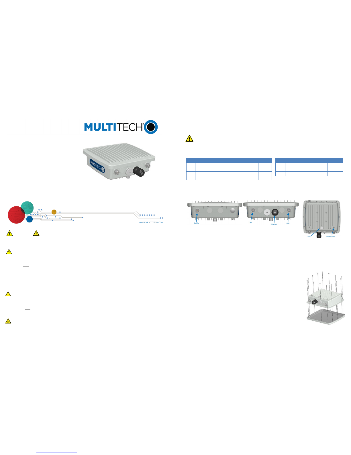
If you do not install the accessory kit when you install the Base Station, cover the LoRa connector to ensure it remains dry.
Package Contents
SIM Card Installation
If your SIM card was not pre-installed, follow these steps to install a SIM card in your device:
WARNING: If yo u conn ected powe r to t he de vice, disco nnect it be fore c ontinuing.
Requirements
P2 Philips screwdriver
Mini SIM Card; MultiTech recommends using an industrial-grade mini SIM c ard suitable for high temperatures
Installing SIM Card
1. Remove the cover by removing the 14 screws as shown in Figure 1.
2. Remove the Conduit from the Base Station by removing the 2 screws as shown in
Figure 2.
3. At the front of the Conduit housing, remove the screw that secures the nameplate to the
Conduit and remove the nameplate as shown in Figure 3.
4. Locate the SIM card holder in the upper right corner of the opening. Gently push the SIM
card into holder face up with the cut corner to the right and the SIM contacts
facing toward the Conduit’s interior as shown in Figure 3.
5. Reattach the MultiTech nameplate to the Conduit using the same screw removed in
Step 3.
6. Reattach the Conduit to the Base Station using the 2 screws removed in Step 2.
7. Reattach the cover.
a. Finger-tighten the 14 screws removed from the cover in Step 1.
b. T ighten all 14 screws in the order shown in Figure 4, starting with number 1. Tighten
all screws to a torque specification of 5.20-6.94 lbf-in (6-8 kgf-cm) to ensure t he product retains its IP67 rating.
Figure 1
Note: Antennas, cables, and a lightning arrestor are part of a separate accessory kit.
Connector Locations
Top View Bottom View Back View
Page 2
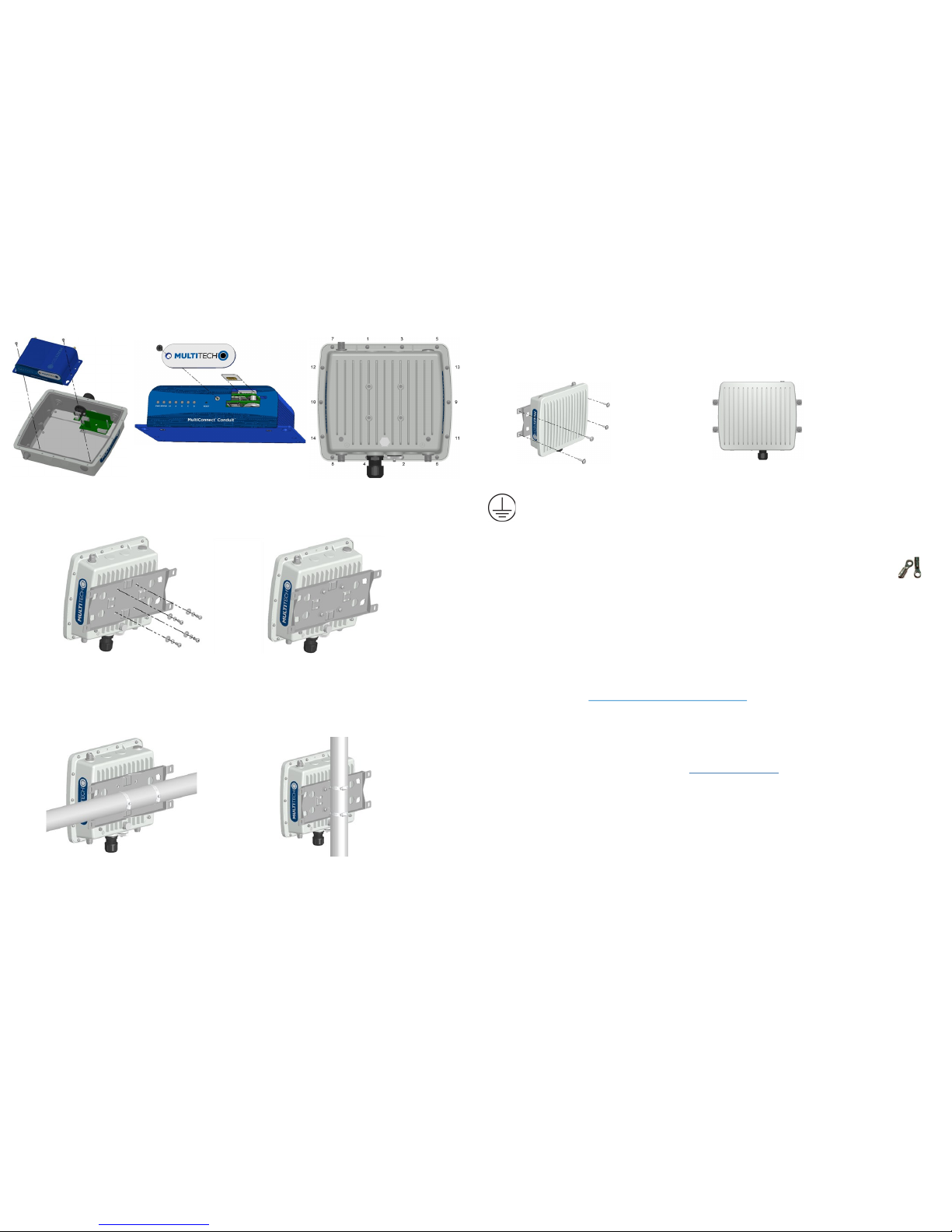
Figure 2 Figure 3 Figure 4
Attaching the Mounting Bracket
To attach the mounting bracket to the Base Station:
Attach the bracket to the back of the Base Station using the supplied screws and washers as s hown.
Mounting on a Pole
To attach the Base Station on a pole:
Attach the Base Station to the pole using the supplied hose clamps.
Installing the Ground Wire
Proper grounding of metal enclosure is required to ensure safety. The ground lug is located on the enclosure
back as shown in the Back image (under Connector Locations). Connectin g the ground lug to an earth ground is
the recommended method. Refer to the National Electric Code or your local codes for addition al information or
contact a licensed electrician for assistance in grounding an installation.
Ground wire (not provided) must be suitable for outdoor location and meet a minimum wire gauge of 14awg or larger. Use
the supplied ground screw to fasten wire.
Ground wire terminal must be closed loop (ring type, see image right) and corrosive free in design. Insert sc rew
though loop terminal and fasten to 15 lbf-in (17.28 kgf-cm).
Attaching Accessories
If you purchased the accessory kit, attach the lightning arrester to the LoRa connector on the to p of the Base Station. Attach
antennas and the Ethernet cable to the connectors as labeled.
Installing the Lighting Arrester
Proper grounding of the lightning arrester is required to ensure proper operation. Connecting th e ground lug on the lightning
arrester to the earth ground is the recommended method. Please refer to the Nationa l Electric Code (or your local codes) for
additional information or contact a licensed electrician for assistance.
Additional Information
For Base Station dimension drawings, MultiConnect Conduit regulatory information and instr uctions for using the
MultiConnect Conduit, go to www.multitech.net/developer/products/conduit.
Regulatory Information
This device complies with Part 15 of the FCC rules and with ICES-003 of Industry Canada for a Class A digital apparatus. Operation
of this device is subject to the following conditions: (1) This device may not cause harmful interference and (2) This device must accept any interference that may cause undesired operation.
MultiTech declares that this device is in compliance with the essential requirements and other relevant provisions of Directive
2014/53/EU. The declaration of conformity may be requested at https://support.multitech.com.
Safety Instructions
For safety and to achieve a good installation, please follow these safety precautions:
Consider safety and performance when selecting an installation site. Remember electric power lines and phone lines look alike.
Assume that any overhead line can kill.
Call your power company and ask them to look at your proposed installation. This is important if raising a mast or tower.
When installing the device:
Do not use a metal ladder.
Do not work on a wet or windy day.
Do dress properly—shoes with rubber soles and heels, rubber gloves, long sleeved shirt or jacket.
If any part of the antenna system comes in contact with a power line, do not touch it or try to remove it yourself. Call your local power
company. They will remove it safely. If an accident occurs, call for emergency help immediately.
Mounting on a Wall
To mount the device on a wall:
Use the four bracket tabs to attach the Base Station to the wall with the supplied screws and anchors .
Page 3

Item
Description
Quantity
Item
Description
Quantity
1
Lightning Arrestor
1
4
5 ft Antenna Cable
1
2
LoRa Antenna
1
5
Antenna Bracket
1
3
4G Antenna
2
6
Installation Guide
1
MultiConnect® ConduitTM IP67 Base Station Accessory Kit
This document illustrates how to connect the lightning arrestor, cable, and antennas to the Base Station. Instructions
for attaching the mounting bracket and mounting the Base Station are included with the Base Station and are also
available at http://www.multitech.net/developer/basestation.
CAUTION: Read all instructions and safety notices before starting installation. Safety notices are included in the
MultiConnect Base Station Installation Guide. Do not connect power to the Base Station until directed to do so.
Package Contents
NOTE: The lightning arrestor comes with a bracket, which is not needed.
Attaching Accessories for a Pole Mounted Base Station
After mounting the Base Station on the pole:
1. Attach the antenna mounting bracket to the LoRa antenna.
2. Mount the antenna bracket to the pole so the top of the antenna bracket is at the
top of the pole and antenna extends above the pole.
3. Attach the lightning arrestor to LoRa antenna.
4. Attach the cable to the lightning arrestor.
5. Attach the cable to the LoRa connector at the top of the Base Station.
6. Attach the 4G antennas to the Cell and Aux connectors on the Base Station.
7. Attach the Ethernet cable (not provided) to the device to supply power and
Ethernet.
Page 4

Attaching Accessories for a Wall Mounted Base Station
After mounting the Base Station on the wall:
1. Attach the antenna mounting bracket to the LoRa antenna.
2. Mount the antenna bracket to the wall.
3. Attach the lightning arrestor to LoRa antenna.
4. Attach the antenna cable to the lightning arrestor.
5. Attach the cable to the LoRa connector at the top of the Base
Station.
6. Attach the 4G antennas to the Cell and Aux connectors on the
Base Station.
7. Attach the Ethernet cable (not provided) to the device to supply
power and Ethernet.
Part: 82101850L Copyright © 2016 Multi-Tech Systems, Inc. All rights reserved
 Loading...