

Page 1

System Installation and
Quick Start Guide
Page 2

System Installation and Quick Start Guide
P/N 82088101, Revision B
Copyright © 2000 by Multi-Tech Systems, Inc.
All rights reserved. This publication may not be reproduced, in whole or in part, without prior
expressed written permission from Multi-Tech Systems, Inc.
Multi-Tech Systems, Inc. makes no representation or warranties with respect to the contents
hereof and specifically disclaims any implied warranties of merchantability or fitness for any
particular purpose. Furthermore, Multi-Tech Systems, Inc. reserves the right to revise this
publication and to make changes from time to time in the content hereof without obligation of
Multi-Tech Systems, Inc., to notify any person or organization of such revisions or changes.
Revision Date Description
A 10/15/98 Manual released.
B 10/25/00 Manual revised for software version 2.53, including E1 support
Multi-Tech, CommPlete, and the Multi-Tech logo are trademarks of Multi-Tech Systems, Inc.
Other trademarks and trade names mentioned in this publication belong to their respective
owners.
Multi-Tech Systems, Inc.
2205 Woodale Drive
Mounds View, Minnesota 55112
(763) 785-3500 or (800) 328-9717
U.S. Fax (763) 785-9874
Technical Support (800) 972-2439
Internet Address: http://www.multitech.com
Page 3

Federal Communications Commission Statement
This equipment has been tested and found to comply with the limits for a
Class A digital device, pursuant to Part 15 of the FCC Rules. These limits are
designed to reasonable protection against harmful interference when the
equipment is operated in a commercial environment. This equipment
generates, uses, and can radiate radio frequency energy, and if not installed
and used in accordance with the instruction manual, may cause harmful
interference to radio communications. Operation of this equipment in a
residential area is likely to cause harmful interference, in which case the user
will be required to correct the interference at his own expense.
Warning: Changes or modifications to this unit not expressly approved by
the party responsible for compliance could void the user’s authority to
operate the equipment.
FCC Fax Warning
The Telephone Consumer Protection Act of 1991 makes it unlawful for any
person to use a computer or other electronic device to send any message via
a telephone fax machine unless such message clearly contains in a margin at
the top or bottom of each page or the first page of the transmission, the date
and time it is sent and an identification of the business or other entity, or
other individual sending the message and the telephone number of the
sending machine or such business, other entity, or individual.
See your fax software manual for setup details.
Exhibit J (Consumer Instructions)
This equipment complies part 68 of the Federal Communications
Commission Rules. On the outside surface of this equipment is a label that
contains, among other information, the FCC registration number. This
information must be provided to the telephone company.
As indicated below, the suitable jack (Universal Service Order Code
connecting arrangement) for this equipment is shown. If applicable, the
facility interface codes (FIC) and service order codes (SOC) are shown.
A FCC-compliant telephone cord and modular plug is provided with this
equipment. This equipment is designed to be connected to the telephone
network or premises wiring using a compatible modular jack which is Part
68 compliant. See installation instructions for details.
If this equipment causes harm to the telephone network, the telephone
company will notify you in advance that temporary discontinuance of
service may be required. But if advance notice is not practical, the telephone
company will notify the customer as soon as possible. Also, you will be
advised of your right to file a complaint with the FCC if you believe it is
necessary.
iii
Page 4

The telephone company may make changes in its facilities, equipment,
operations, or procedures that could affect the operation of the equipment. If
this happens, the telephone company will provide advance notice in order
for you to make necessary modifications in order to maintain uninterrupted
service.
If trouble is experienced with this equipment (the model of which is
indicated below) please contact Multi-Tech Systems, Inc. at the address
shown below for details of how to have repairs made. If the equipment is
causing harm to the network, the telephone company may request you to
remove the equipment from the network until the problem is resolved.
No repairs are to be made by you. Repairs are to be made only by Multi-Tech
Systems or its licensees. Unauthorized repairs void registration and
warranty.
Manufacturer: Multi-Tech Systems, Inc.
Trade Name: CommPlete
Model Number: CC2400, CC9600
FCC Registration Number: AU7USA-31090-DE-E
Facility Interface Code: 04DU9-ISN, 04DU9-BN
Service Order Code: 6.0N
Modular Jack (USOC): RJ48C
Service Center in USA: Multi-Tech Systems, Inc.
2205 Woodale Drive
Mounds View, MN 55112
(763) 785- 3500 Fax (763) 785-9874
EMC, Safety, and Terminal Directive Compliance
The CE mark is affixed to this Multi-Tech product to confirm compliance
with the following European Community Directives:
Council Directive 89/336/EEC of 3 May 1989 on the approximation of the
laws of Member States relating to electromagnetic compatibility; and
Council Directive 73/23/EEC of 19 February 1973 on the harmonization of
the laws of Member States relating to electrical equipment designed for use
within certain voltage limits; and
Council Directive 91/263/EEC of 29 April 1991 on the approximation of the
laws of the Member States concerning telecommunications terminal
equipment, including the mutual recognition of their conformity;
each amended by Council Directive 93/68/EEC of 22 July 1993 on the
harmonization of CE marking requirements.
iv
Page 5

Canadian Limitations Notice
Notice: The ringer equivalence number (REN) assigned to each terminal
device provides an indication of the maximum number of terminals allowed
to be connected to a telephone interface. The termination of a interface may
consist of any combination of devices subject only to the requirement that the
sum of the ringer equivalence numbers of all the devices does not exceed 5.
Notice: The Industry Canada label identifies certificated equipment. This
certification means that the equipment meets certain telecommunications
network protective, operational and safety requirements. The Industry
Canada does not guarantee the equipment will operate to the user’s
satisfaction.
Before installing this equipment, users should ensure that it is permissible to
be connected to the facilities of the local telecommunications company. The
equipment must also be installed using an acceptable method of connection.
The customer should be aware that compliance with the above conditions
may not prevent degradation of service in some situations.
Repairs to certified equipment should be made by an authorized Canadian
maintenance facility designated by the supplier. Any repairs or alterations
made by the user to this equipment, or equipment malfunctions, may give
the telecommunications company cause to request the user to disconnect the
equipment.
Users should ensure for their own protection that the electrical ground
connections of the power utility, telephone lines and internal metallic water
pipe system, if present, are connected together. This precaution may be
particularly important in rural areas.
Caution: Users should not attempt to make such connections themselves, but
should contact the appropriate electric inspection authority, or electrician, as
appropriate.
This digital apparatus does not exceed the Class B limits for radio noise
emissions from digital apparatus set out in the Radio Interference Regulation
of the Canadian Department of Communications.
Le présent appareil numérique n’émet pas de bruits radioélectriques
dépassant les limites applicables aux appareils numériques de la classe B
prescrites dans le Règlement sur le brouillage radioélectrique édicté par le
ministère des Communications du Canada.
v
Page 6

vi
Page 7

Table of Contents
1 System Installation
Introduction..........................................................................................................................10
Pre-Installation Notes........................................................................................................10
Safety Warnings..................................................................................................................11
CC9600 Installation Procedures.....................................................................................11
T1/Dual T1 Installation Procedure..........................................................................12
E1 Installation Procedures...........................................................................................14
PRI (23B+D) Installation Procedure.........................................................................14
EPRI (30B+D) Installation Procedure......................................................................18
Safety Warnings..................................................................................................................20
CC2400 Installation Procedure .......................................................................................20
T1/Dual T1 Installation Procedure..........................................................................21
E1 Installation Procedure.............................................................................................23
PRI (23B+D) Installation Procedure.........................................................................23
EPRI (30B+D) Installation Procedure......................................................................27
2 Configuration Quick Start
Introduction..........................................................................................................................30
T1/Dual Configuration Procedure...............................................................................31
Getting Version Information ......................................................................................49
E1 Configuration Procedure...........................................................................................50
Getting Version Information ......................................................................................66
PRI (23B+D) Configuration Procedure ........................................................................67
Getting Version Information ......................................................................................85
EPRI (30B+D) Configuration Procedure.....................................................................86
Getting Version Information ....................................................................................102
Verifying Software/Firmware Version Information............................................103
3 Warranty and Technical Support
Limited Warranty.............................................................................................................106
Technical Support.............................................................................................................106
Appendixes
Appendix A – Additional Site Information Sheets................................................108
vii
Page 8

viii
Page 9

1 System Installation
Page 10

System Installation and Quick Start Guide
Introduction
This chapter describes briefly how to unpack and install the hardware
components of the CommPlete Communications Server. Full instructions for
the installation of each component can be found in its respective user guide.
The following installation procedures have been organized based on product
type and configuration. After reading the Pre-Installation Notes, you should
refer to the initial installation page for your product (page 11 for CC9600
users, and page 20 for cc2400 users) and then proceed with the procedure
that matches your setup.
Pre-Installation Notes
Warning: Interconnection directly, or by way of other apparatus, of ports
marked “SAFETY WARNING see instructions for use” with ports marked or
not so marked may produce hazardous conditions on the network. Advice
should be obtained from a competent engineer before such a connection is
made.
• All installation must be done by a qualified service person.
• To reduce emissions, be sure to use blanking plates to cover empty slots
in the CC9600 or CC2400 chassis.
• This product is intended to be hard-wired to the network. The final
connection to the network is the responsibility of the public
telecommunications network operator or a person authorized by that
operator.
• Any other apparatus, including cable and wiring, connected between the
MT5634HD8 modem and the point of connection to any speech band
circuit shall comply with the following:
1. The overall characteristics of this apparatus shall be such as to
introduce no material effect upon the electrical conditions presented
to one another by the modem and he speech band circuit.
2. The apparatus shall comprise only
a. apparatus approved for the purpose of connection between the
modem and a speech band circuit; and
b. cable and wiring complying with a code of practice for the
installation of equipment covered by this part of BS 6328 or such
other requirements as may be applicable.
Note: Such apparatus may have been approved subject to limitations in its
use.
10
Page 11

Safety Warnings
• Never install telephone wiring during a lightning storm.
• Never install telephone jacks in wet locations unless the jacks are
specifically designed for wet locations.
• Never touch uninsulated telephone wires or terminals unless the
telephone line has been disconnected at the network interface.
• Use caution when installing or modifying telephone lines.
• Avoid using a telephone (other than a cordless type) during an electrical
storm. There may be a remote risk of electrical shock from lightning.
• Do not use the telephone to report a gas leak in the vicinity of the leak.
• Ports that are connected to other apparatus are defined as SELV. To
ensure conformity to EN 41003, ensure that these ports are only
connected to the same type on the other apparatus.
CC9600 Installation Procedures
1 System Installation
The components of the CommPlete Communication Server are packed in
several cartons. Unpack and assemble them in the order indicated, checking
for shipping damage as you do so. The following instructions are for the
CC9600 CommPlete. Instructions for the CC2400 CommPlete follow. The
procedures are divided into segment types and, as such, you should refer to
the installation procedure appropriate to your setup.
• To install a T1 configuration, refer to page 12.
• To install an E1 configuration, refer to page 14.
• To install a PRI (23B+D) configuration, refer to page 16.
• To install a EPRI (30B+D) configuration, refer to page 18.
Note: If this is a first-time installation or you need more detailed instructions,
refer to the user guides for the individual components.
11
Page 12
System Installation and Quick Start Guide
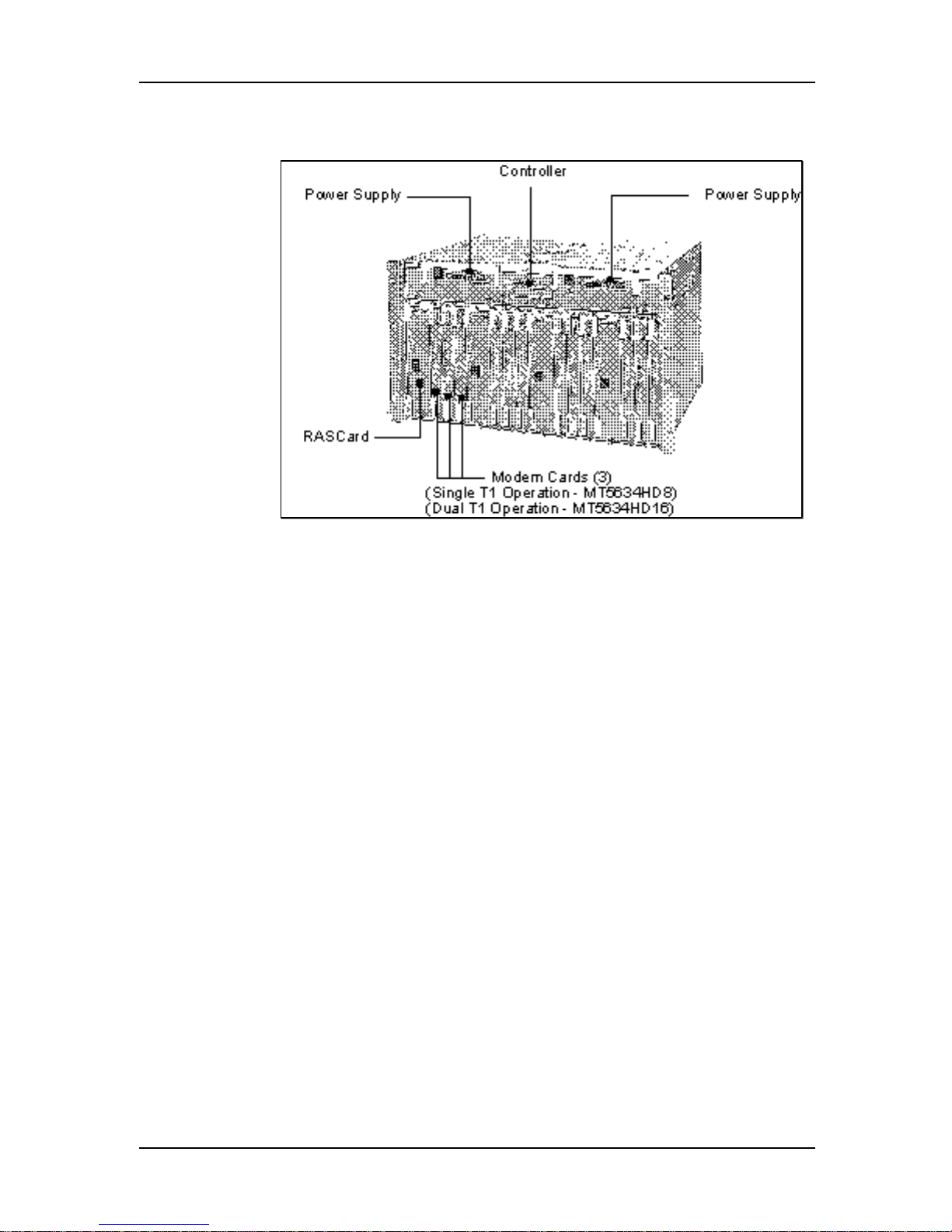
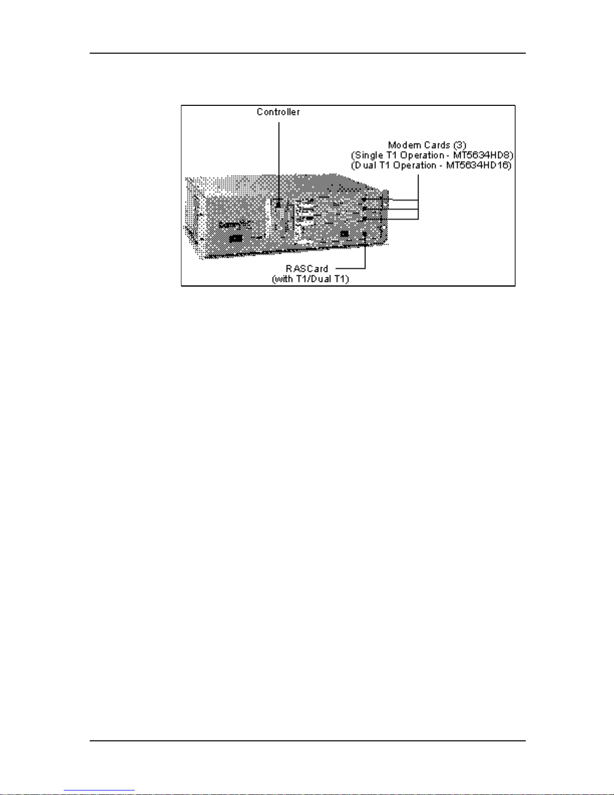
T1/Dual T1 Installation Procedure
Figure 1. CommPlete CC9600 with Four T1/Dual T1 Segments
1. Unpack the CC9600 chassis and place it on a bench or install it in a
standard 19-inch rack. In addition to the chassis, the carton contains two
power cord sets and the documentation set.
2. Plug the power cords into the back of the chassis, but do not connect
them to power yet.
3. Unpack the MR9600 controller assembly, observing standard static
electricity precautions. Insert it carefully into the plastic guides in the
chassis and slide it in until you feel it mate with the bus connectors
inside the chassis. Tighten the retaining screws. Retain the enclosed
serial cable for use in configuring the controller.
4. Unpack the PS9600 power supplies. Carefully insert them into the
chassis and slide them in until you feel them mate with the bus
connectors inside the chassis. Tighten the retaining screws.
5. Unpack each RAS96 RASCard, observing standard static electricity
precautions. Engage the edges of the card in the metal card guides of slot
1, 5, 9, or 13, and slide it in until you feel it mate with the bus connectors
inside the chassis. Tighten the retaining screws.
6. Insert the back panel for each RASCard into the rear of the chassis and
tighten the retaining screw.
7. Unpack each modem card, observing standard static electricity
precautions. Engage the edges of the card in the metal card guides of a
device slot and slide it in until you feel it mate with the bus connectors
inside the chassis. Tighten the retaining screws.
8. Plug the two power cord sets into AC outlets.
12
Page 13

1 System Installation
9. Plug one end of an Ethernet cable into the LAN Ethernet 10Base-T
connector on the back of the chassis. Plug the other end into the Ethernet
wall jack.
10. Turn on the PS9600 power supplies. The power supply indicators should
light and the controller indicators should flash during the power-on selftest.
11. Connect one end of the provided T1 cable(s) to the T1 jack(s) on the
RASCard, and the other end to a T1 wall jack.
Note: Do not connect the T1 line(s) until you are ready to proceed with
the configuration procedures
12. Turn on each RASCard. The indicator in the power switch and front
panel should light.
Installation of the CommPlete Communications Server hardware is complete. Your
next step is to configure the controller, RASCard, and T1 interface(s) so they can
communicate with the outside world. Please turn to Chapter 2.
13
Page 14
System Installation and Quick Start Guide
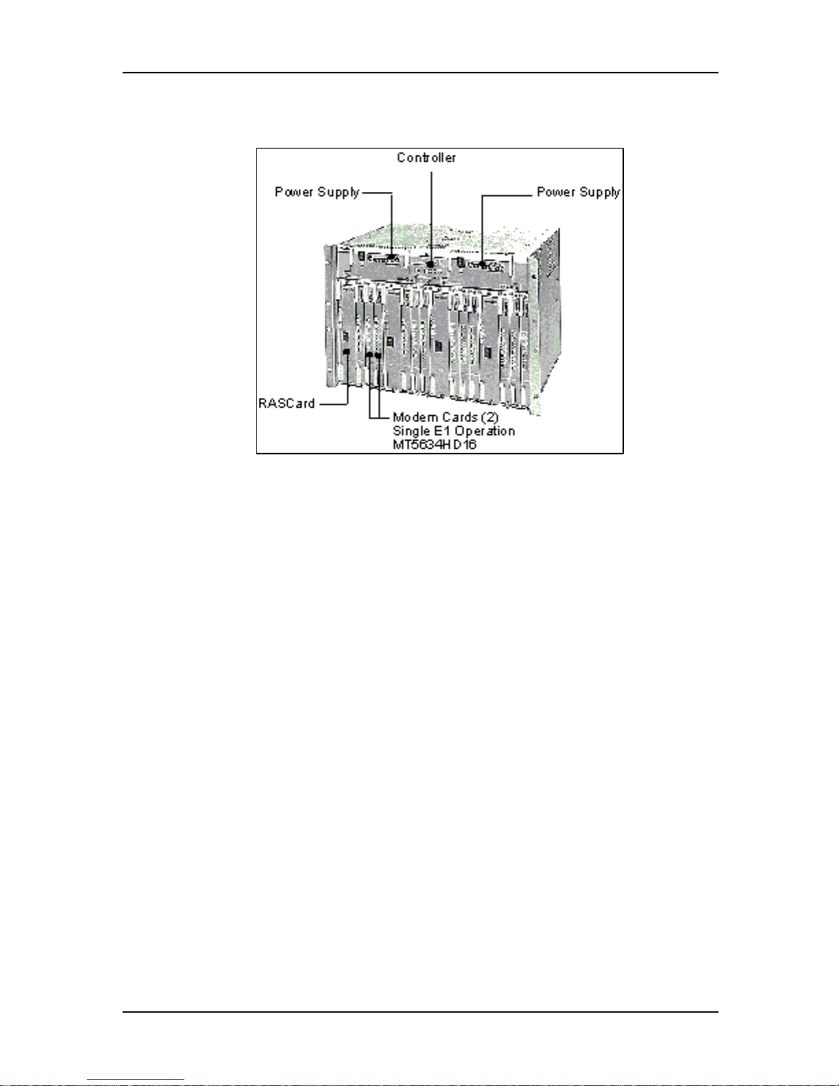
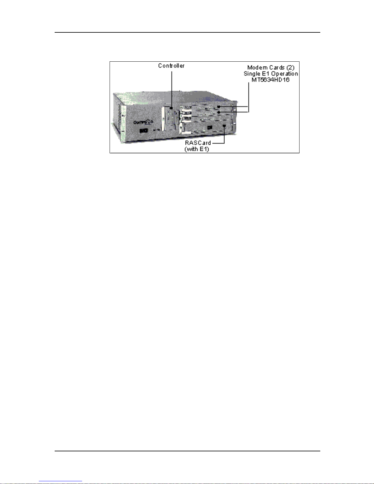
E1 Installation Procedure
Figure 2. CommPlete CC9600 with up to 4 E1 segments
1. Unpack the CC9600 chassis and place it on a bench or install it in a
standard 19-inch rack. In addition to the chassis, the carton contains two
power cord sets and the documentation set.
2. Plug the power cords into the back of the chassis, but do not connect
them to power yet.
3. Unpack the MR9600 controller assembly, observing standard static
electricity precautions. Insert it carefully into the plastic guides in the
chassis and slide it in until you feel it mate with the bus connectors
inside the chassis. Tighten the retaining screws. Retain the enclosed
serial cable for use in configuring the controller.
4. Unpack the PS9600 power supplies. Carefully insert them into the
chassis and slide them in until you feel them mate with the bus
connectors inside the chassis. Tighten the retaining screws.
5. Unpack each RAS96 RASCard, observing standard static electricity
precautions. Engage the edges of the card in the metal card guides of slot
1, 5, 9, or 13, and slide it in until you feel it mate with the bus connectors
inside the chassis. Tighten the retaining screws.
6. Insert the back panel for each RASCard into the rear of the chassis and
tighten the retaining screw.
7. Unpack each modem card, observing standard static electricity
precautions. Engage the edges of the card in the metal card guides of a
device slot and slide it in until you feel it mate with the bus connectors
inside the chassis. Tighten the retaining screws.
8. Plug the two power cord sets into AC outlets.
9. Plug one end of an Ethernet cable into the LAN Ethernet 10Base-T
connector on the back of the chassis. Plug the other end into the Ethernet
wall jack.
14
Page 15

1 System Installation
10. Turn on the PS9600 power supplies. The power supply indicators should
light and the controller indicators should flash during the power-on selftest.
11. Connect one end of the provided E1 cable(s) to the E1 jack(s) on the
RASCard, and the other end to an E1 wall jack.
Note: Do not connect the E1 line(s) until you are ready to proceed with
the configuration procedures
12. Turn on each RASCard. The indicator in the power switch and front
panel should light.
Installation of the CommPlete Communications Server hardware is complete. Your
next step is to configure the controller, RASCard, and E1 interface(s) so they can
communicate with the outside world. Please turn to Chapter 2.
15
Page 16
System Installation and Quick Start Guide
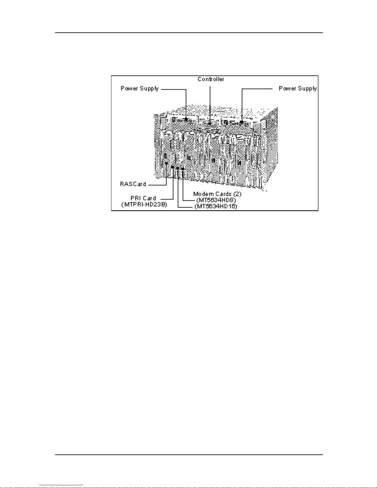
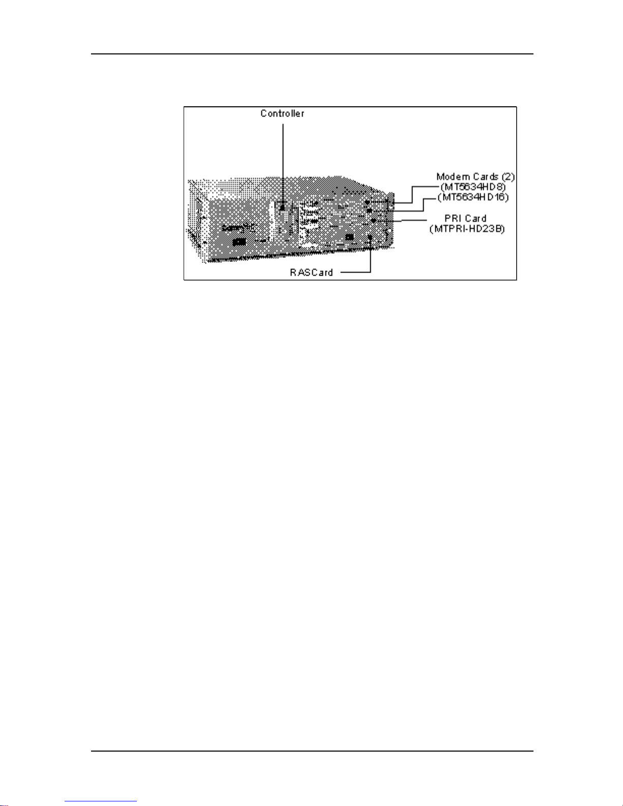
PRI (23B+D) Installation Procedure
Figure 3. CommPlete CC9600 with Four PRI (23B+D) Segments
1. Unpack the CC9600 chassis and place it on a bench or install it in a
standard 19-inch rack. In addition to the chassis, the carton contains two
power cord sets and the documentation set.
2. Plug the power cords into the back of the chassis, but do not connect
them to power yet.
3. Unpack the MR9600 controller assembly, observing standard static
electricity precautions. Insert it carefully into the plastic guides in the
chassis and slide it in until you feel it mate with the bus connectors
inside the chassis. Tighten the retaining screws. Retain the enclosed
serial cable for use in configuring the controller.
4. Unpack the PS9600 power supplies. Carefully insert them into the
chassis and slide them in until you feel them mate with the bus
connectors inside the chassis. Tighten the retaining screws.
5. Unpack each RAS96 RASCard, observing standard static electricity
precautions. Engage the edges of the card in the metal card guides of slot
1, 5, 9, or 13, and slide it in until you feel it mate with the bus connectors
inside the chassis. Tighten the retaining screws.
6. Insert the back panel for each RASCard into the rear of the chassis and
tighten the retaining screw.
7. Unpack each PRI Card (MTPRI-HD23B), observing standard static
electricity precautions. Engage the edges of the card in the metal card
guides of slot 2, 6, 10, or 14, and slide it in until you feel it mate with the
bus connectors inside the chassis. Tighten the retaining screws.
16
Page 17

1 System Installation
8. Unpack each modem card, observing standard static electricity
precautions. Engage the edges of the MT5634HD16 card(s) in the metal
card guides of a slot 3,7,11, or 15 and slide it in until you feel it mate with
the bus connectors inside the chassis. Engage the edges of the
MT5634HD8 card(s) in the metal card guides of a slot 4,8,12, or 16 and
slide it in until you feel it mate with the bus connectors inside the
chassis. Tighten the retaining screws.
9. Plug the two power cord sets into AC outlets.
10. Plug one end of an Ethernet cable into the LAN Ethernet 10Base-T
connector on the back of the chassis. Plug the other end into the Ethernet
wall jack.
11. Turn on the PS9600 power supplies. The power supply indicators should
light and the controller indicators should flash during the power-on selftest.
12. Connect one end of the provided RJ48 cable to the PRI interface jack on
the MTPRI-HD23B card, and the other end to a PRI wall jack.
Note: Do not connect the PRI line(s) until you are ready to proceed with
the configuration procedures.
13. Turn on each RASCard. The indicator in the power switch and front
panel should light.
Installation of the CommPlete Communications Server hardware is complete. Your
next step is to configure the controller, RASCard, and PRI interface so they can
communicate with the outside world. Please turn to Chapter 2.
17
Page 18
System Installation and Quick Start Guide
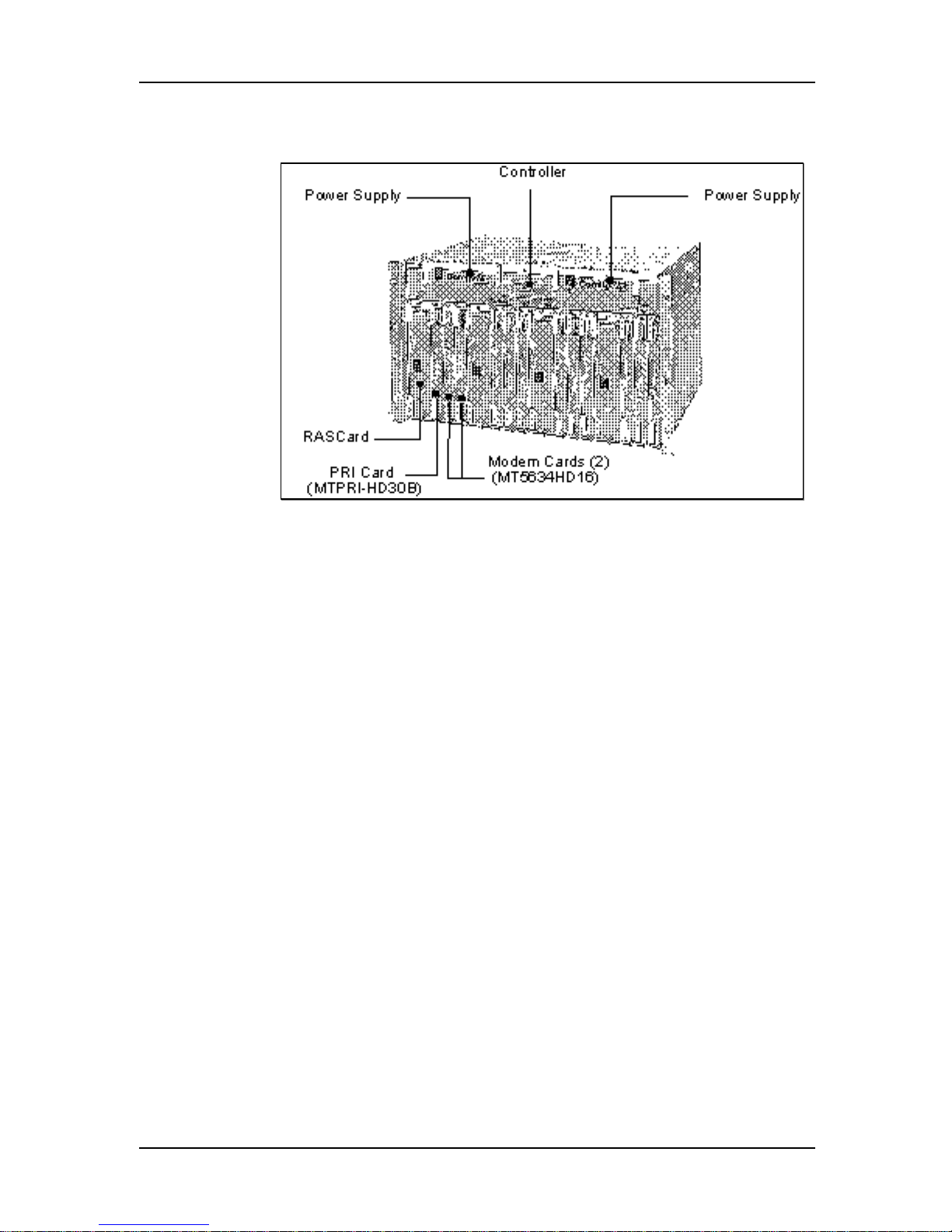
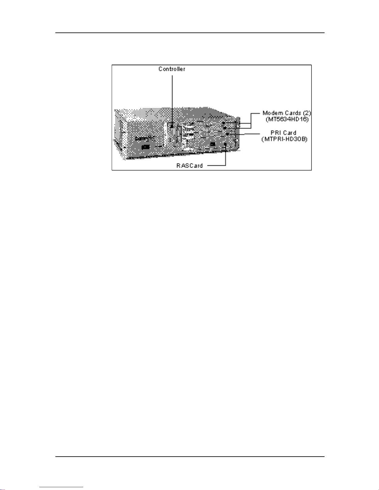
EPRI (30B+D) Installation Procedure
Figure 4. CommPlete CC9600 with Four EPRI (30B+D) Segments
1. Unpack the CC9600 chassis and place it on a bench or install it in a
standard 19-inch rack. In addition to the chassis, the carton contains two
power cord sets and the documentation set.
2. Plug the power cords into the back of the chassis, but do not connect
them to power yet.
3. Unpack the MR9600 controller assembly, observing standard static
electricity precautions. Insert it carefully into the plastic guides in the
chassis and slide it in until you feel it mate with the bus connectors
inside the chassis. Tighten the retaining screws. Retain the enclosed
serial cable for use in configuring the controller.
4. Unpack the PS9600 power supplies. Carefully insert them into the
chassis and slide them in until you feel them mate with the bus
connectors inside the chassis. Tighten the retaining screws.
5. Unpack each RAS96 RASCard, observing standard static electricity
precautions. Engage the edges of the card in the metal card guides of slot
1, 5, 9, or 13, and slide it in until you feel it mate with the bus connectors
inside the chassis. Tighten the retaining screws.
6. Insert the back panel for each RASCard into the rear of the chassis and
tighten the retaining screw.
7. Unpack each EPRI Card (MTPRI-HD30B), observing standard static
electricity precautions. Engage the edges of the card in the metal card
guides of slot 2, 6, 10, or 14, and slide it in until you feel it mate with the
bus connectors inside the chassis. Tighten the retaining screws
8. Unpack each modem card, observing standard static electricity
precautions. Engage the edges of the card in the metal card guides of a
device slot and slide it in until you feel it mate with the bus connectors
inside the chassis. Tighten the retaining screws.
18
Page 19

1 System Installation
9. Plug the two power cord sets into AC outlets.
10. Plug one end of an Ethernet cable into the LAN Ethernet 10Base-T
connector on the back of the chassis. Plug the other end into the Ethernet
wall jack.
11. Turn on the PS9600 power supplies. The power supply indicators should
light and the controller indicators should flash during the power-on selftest.
12. Connect one end of the provided RJ48 cable to the PRI interface jack on
the MTPRI-HD30B card, and the other end to a PRI line wall jack.
Note: Do not connect the PRI line(s) until you are ready to proceed with
the configuration procedures
13. Turn on each RASCard. The indicator in the power switch and front
panel should light.
Installation of the CommPlete Communications Server hardware is complete. Your
next step is to configure the controller, RASCard, and EPRI interface so they can
communicate with the outside world. Please turn to Chapter 2.
19
Page 20

System Installation and Quick Start Guide
Safety Warnings
• Never install telephone wiring during a lightning storm.
• Never install telephone jacks in wet locations unless the jacks are
specifically designed for wet locations.
• Never touch uninsulated telephone wires or terminals unless the
telephone line has been disconnected at the network interface.
• Use caution when installing or modifying telephone lines.
• Avoid using a telephone (other than a cordless type) during an electrical
storm. There may be a remote risk of electrical shock from lightning.
• Do not use the telephone to report a gas leak in the vicinity of the leak.
• Ports that are connected to other apparatus are defined as SELV. To
ensure conformity to EN 41003, ensure that these ports are only
connected to the same type on the other apparatus.
CC2400 Installation Procedure
The components of the CommPlete Communication Server are packed in
several cartons. Unpack and assemble them in the order provided, checking
for shipping damage as you do so. The following instructions are for the
CC2400 CommPlete. Instructions for the CC9600 CommPlete precede these
instructions. The procedures are divided into segment types; therefore, you
should refer to the installation procedure appropriate to your setup.
• To install a T1 configuration, refer to page 21.
• To install an E1 configuration, refer to page 23.
• To install a PRI (23B+D) configuration, refer to page 25.
• To install an EPRI (30B+D) configuration, refer to page 27.
Note: If this is a first-time installation or you need more detailed instructions,
refer to the user guides for the individual components.
20
Page 21
T1/Dual T1 Installation Procedure
Figure 5. CommPlete CC2400 with One T1/Dual T1 Segment
1. Unpack the CC2400 chassis and place it on a bench or install it in a
standard 19-inch rack. In addition to the chassis, the carton contains a
power cord set and the documentation set.
2. Plug the power cord into the back of the chassis, but do not connect to
power yet.
3. Unpack the MR9600 controller assembly, observing standard static
electricity precautions. Insert it carefully into the plastic guides in the
chassis and slide it in until you feel it mate with the bus connectors
inside the chassis. Tighten the retaining screws. Retain the enclosed
serial cable for use in configuring the controller.
4. Unpack the RAS96 RASCard, observing standard static electricity
precautions. Engage the edges of the card in the metal card guides of slot
1 and slide it in until you feel it mate with the bus connectors inside the
chassis. Tighten the retaining screws.
5. Insert the back panel for the RASCard into the rear of the chassis and
tighten the retaining screw.
6. Unpack each modem card, observing standard static electricity
precautions. Engage the edges of the card in the metal card guides of a
device slot and slide it in until you feel it mate with the bus connectors
inside the chassis. Tighten the retaining screws.
7. Plug the power cord set into AC outlets.
8. Plug one end of an Ethernet cable into the LAN Ethernet 10Base-T
connector on the back of the chassis. Plug the other end into the Ethernet
wall jack.
9. Apply power to the CC2400. The power supply indicators should light
and the controller indicators should flash during the power-on self-test.
1 System Installation
21
Page 22

System Installation and Quick Start Guide
10. Connect one end of the provided T1 cable(s) to the T1 jack(s) on the
RASCard, and the other end to a T1 wall jack.
Note: Do not connect the T1 line(s) until you are ready to perform the
configuration procedures.
11. Turn on the RASCard. The indicator in the power switch and front panel
should light.
Installation of the CommPlete Communications Server hardware is complete. Your
next step is to configure the controller, RASCard, and T1 interface(s) so they can
communicate with the outside world. Please turn to Chapter 2.
22
Page 23
E1 Installation Procedure
Figure 6. CommPlete CC2400 with One E1 segment
1. Unpack the CC2400 chassis and place it on a bench or install it in a
standard 19-inch rack. In addition to the chassis, the carton contains a
power cord set and the documentation set.
2. Plug the power cord into the back of the chassis, but do not connect to
power yet.
3. Unpack the MR9600 controller assembly, observing standard static
electricity precautions. Insert it carefully into the plastic guides in the
chassis and slide it in until you feel it mate with the bus connectors
inside the chassis. Tighten the retaining screws. Retain the enclosed
serial cable for use in configuring the controller.
4. Unpack the RAS96 RASCard, observing standard static electricity
precautions. Engage the edges of the card in the metal card guides of slot
1 and slide it in until you feel it mate with the bus connectors inside the
chassis. Tighten the retaining screws.
5. Insert the back panel for the RASCard into the rear of the chassis and
tighten the retaining screw.
6. Unpack each modem card, observing standard static electricity
precautions. Engage the edges of the card in the metal card guides of a
device slot and slide it in until you feel it mate with the bus connectors
inside the chassis. Tighten the retaining screws.
7. Plug the power cord set into AC outlets.
8. Plug one end of an Ethernet cable into the LAN Ethernet 10Base-T
connector on the back of the chassis. Plug the other end into the Ethernet
wall jack.
9. Apply power to the CC2400. The power supply indicators should light
and the controller indicators should flash during the power-on self-test.
1 System Installation
23
Page 24

System Installation and Quick Start Guide
10. Connect one end of the provided E1 cable(s) to the E1 jack(s) on the
RASCard, and the other end to an E1 wall jack.
Note: Do not connect the E1 line(s) until you are ready to perform the
configuration procedures.
11. Turn on the RASCard. The indicator in the power switch and front panel
should light.
Installation of the CommPlete Communications Server hardware is complete. Your
next step is to configure the controller, RASCard, and E1 interface(s) so they can
communicate with the outside world. Please turn to Chapter 2.
24
Page 25
PRI (23B+D) Installation Procedure
Figure 7. CommPlete CC2400 with One PRI (23B+D) Segment
1. Unpack the CC2400 chassis and place it on a bench or install it in a
standard 19-inch rack. In addition to the chassis, the carton contains a
power cord set and the documentation set.
2. Plug the power cord into the back of the chassis, but do not connect to
power yet.
3. Unpack the MR9600 controller assembly, observing standard static
electricity precautions. Insert it carefully into the plastic guides in the
chassis and slide it in until you feel it mate with the bus connectors
inside the chassis. Tighten the retaining screws. Retain the enclosed
serial cable for use in configuring the controller.
4. Unpack the RAS96 RASCard, observing standard static electricity
precautions. Engage the edges of the card in the metal card guides of slot
1 and slide it in until you feel it mate with the bus connectors inside the
chassis. Tighten the retaining screws.
5. Insert the back panel for the RASCard into the rear of the chassis and
tighten the retaining screw.
6. Unpack the PRI Card (MTPRI-HD23B), observing standard static
electricity precautions. Engage the edges of the card in the metal card
guides of slot 2 and slide it in until you feel it mate with the bus
connectors inside the chassis. Tighten the retaining screws.
7. Unpack each modem card, observing standard static electricity
precautions. Engage the edges of the MT5634HD16 card in the metal
card guides of slot 3 and slide it in until you feel it mate with the bus
connectors inside the chassis. Engage the edges of the MT5634HD8 card
in the metal card guides of slot 4 and slide it in until you feel it mate with
the bus connectors inside the chassis. Tighten the retaining screws.
8. Plug the power cord set into AC outlets.
9. Plug one end of an Ethernet cable into the LAN Ethernet 10Base-T
connector on the back of the chassis. Plug the other end into the Ethernet
wall jack.
1 System Installation
25
Page 26

System Installation and Quick Start Guide
10. Apply power to the CC2400. The power supply indicators should light
and the controller indicators should flash during the power-on self-test.
11. Connect one end of the provided RJ48 cable to the PRI interface jack on
the MTPRI-HD23B card, and the other end to a PRI line wall jack.
Note: Do not connect the PRI line until you are ready to perform the
configuration procedures.
12. Turn on the RASCard. The indicator in the power switch and front panel
should light.
Installation of the CommPlete Communications Server hardware is complete. Your
next step is to configure the controller, RASCard, and PRI interface so they can
communicate with the outside world. Please turn to Chapter 2.
26
Page 27
EPRI (30B+D) Installation Procedure
Figure 8. CommPlete CC2400 with One EPRI (30B+D) Segment
1. Unpack the CC2400 chassis and place it on a bench or install it in a
standard 19-inch rack. In addition to the chassis, the carton contains a
power cord set and the documentation set.
2. Plug the power cord into the back of the chassis, but do not connect to
power yet.
3. Unpack the MR9600 controller assembly, observing standard static
electricity precautions. Insert it carefully into the plastic guides in the
chassis and slide it in until you feel it mate with the bus connectors
inside the chassis. Tighten the retaining screws. Retain the enclosed
serial cable for use in configuring the controller.
4. Unpack the RAS96 RASCard, observing standard static electricity
precautions. Engage the edges of the card in the metal card guides of slot
1 and slide it in until you feel it mate with the bus connectors inside the
chassis. Tighten the retaining screws.
5. Insert the back panel for the RASCard into the rear of the chassis and
tighten the retaining screw.
6. Unpack the PRI Card (MTPRI-HD23B), observing standard static
electricity precautions. Engage the edges of the card in the metal card
guides of slot 2 and slide it in until you feel it mate with the bus
connectors inside the chassis. Tighten the retaining screws
7. Unpack each modem card, observing standard static electricity
precautions. Engage the edges of the card in the metal card guides of a
device slot and slide it in until you feel it mate with the bus connectors
inside the chassis. Tighten the retaining screws.
8. Plug the power cord set into AC outlets.
9. Plug one end of an Ethernet cable into the LAN Ethernet 10Base-T
connector on the back of the chassis. Plug the other end into the Ethernet
wall jack.
10. Apply power to the CC2400. The power supply indicators should light
and the controller indicators should flash during the power-on self-test.
1 System Installation
27
Page 28

System Installation and Quick Start Guide
11. Connect one end of the provided RJ48 cable to the PRI interface jack on
the MTPRI-HD23B card, and the other end to a PRI line wall jack.
Note: Do not connect the PRI line until you are ready to perform the
configuration procedures.
12. Turn on the RASCard. The indicator in the power switch and front panel
should light.
Installation of the CommPlete Communications Server hardware is complete. Your
next step is to configure the controller, RASCard, and EPRI interface so they can
communicate with the outside world. Please turn to Chapter 2.
28
Page 29

2 Configuration Quick Start
Page 30

System Installation and Quick Start Guide
Introduction
This section describes how to get your new CommPlete Communications
Server up and running as quickly as possible. Your first step was to install
the CommPlete and connect it to power, to your LAN, and to your WAN
lines. Now, to enable them to communicate with the outside world, you
must configure the MR9600 controller, the RAS96 RASCards, and the T1/E1
daughter card or PRI/EPRI card. The following configuration procedures
require a terminal or a PC with terminal emulation connected to the
configuration port of the MR9600 controller. The procedures have been
organized based on configuration type. Proceed to the procedure
appropriate to your setup.
• For T1 configuration, refer to page 31.
• For E1 configuration, refer to page 50.
• For PRI (23B+D) configuration, refer to page 67.
• For EPRI (30B+D) configuration, refer to page 87.
When you have completed the configuration of your CommPlete, complete
the Verifying Software Firmware Version Information section of this chapter.
This procedure will verify that you have the most current resources available
for you CommPlete. If you need further instructions, refer to the individual
User Guide for each component, or refer to the on-line help provided with
your software. At the end of the verification procedure, you will be
instructed to go to the following link on the Multi-Tech web site:
http://www.multitech.com/support/
Use the Product Support list box to select Commplete.
The Commplete web page provides you with a list of the latest firmware and
software revisions. In addition this site offers links to the Multi-Tech FTP
site, should you need to upgrade. Compare the list found on this web page to
the list you have assembled on your Site Planning sheet. For instructions on
upgrading a specific element, refer to the instructions provided in the
individual User Guides.
Note: If you experience any problems or questions, contact Technical
Support, Monday - Friday, 8:30AM to 5:00PM (Central Time), by calling (800)
972-2439.
30
Page 31

2 Configuration Quick Start
T1/Dual Configuration Procedure
Fill out the following Site Information sheet prior to configuration. This form can be useful as a
quick reference and troubleshooting tool.
31
Page 32

System Installation and Quick Start Guide
The following procedure describes how to set your default configurations
and then configure your individual devices.
1. Turn off all power to the CommPlete chassis.
2. Using the provided 9-pin null modem cable (PN 45009600), connect a
COM port on a PC to the Config Port connector on the back of the
CommPlete chassis. Turn on the PC and run a standard datacomm
program, in direct connect mode. To communicate with the controller
card, use the following settings: 115,200 bps, 8N1, and no flow control.
3. Turn on the power supply or supplies for the CommPlete chassis. If the
CommPlete Communications Server is already on, press the reset button
on the MR9600 controller’s front panel with the end of a paper clip. A
screen similar to the following appears:
Welcome to the CommPlete Communications Server Controller
(MR9600)
Version 2.53 (Oct 25 2000 16:21:50) -- 10/26/2000 2:38pm
System not started because IP address is not set.
Login as supervisor.
Username:
4. At the username prompt, type supervisor and press ENTER.
System Defaults Configuration
Note: as you configure the system defaults, make note of your settings
on the T1 Site Information sheet.
5. At the password prompt, type supervisor and press ENTER. If you are
configuring the CommPlete Communications Server for the first time, a
screen similar to the following appears:
Password: **********
Detecting devices ..starting.........done
Waiting for T1/E1 Version Information
Push any key to abort the wait.
(Aborting could cause any E1 cards to be identified as T1)
Getting System Defaults
1 new Controller device was detected
4 new RAS device(s) were detected
3 new T1 device(s) were detected
1 new PRI card(s) were detected
MultiCommManager Environment Setup
1. System Defaults Setup (Required)
2. Device Specific Setup (Required)
Enter Selection (q(uit), <1>): 1
32
Page 33

2 Configuration Quick Start
6. Type 1 and press ENTER to configure the system defaults. The following
menu appears:
System Defaults Setup
1. Network Defaults (Required)
2. Ras Defaults (Required)
3. Ras Security Defaults (Required)
4. T1 Defaults (Required)
5. E1 Defaults (Required)
6. PRI Defaults (Required)
Enter Selection (-(previous), q(uit), <1>): 1
The settings you create in the System Defaults Setup menu become the
default settings for any new device that is inserted into the CommPlete
chassis. In data entry lines, current settings are displayed in angle
brackets. Press Enter to accept a current setting and continue to the next
option or menu; press - (hyphen) to go back to the previous menu; or
press q to quit.
7. In the System Defaults Setup menu, type 1 and press ENTER to set up
network defaults. The following screen appears:
Default Gateway:0.0.0.0
Subnet Mask:0.0.0.0
Primary DNS Server:0.0.0.0
Backup DNS Server:0.0.0.0
Press ENTER to display the Default Gateway option:
Default Gateway (-(previous), q(uit), <0.0.0.0>):
8. Press ENTER to accept the default address of 0.0.0.0, or type the IP
address for the default gateway (the local router if any), for example
192.168.4.1, and press ENTER. When you press ENTER, the Subnet Mask
option appears:
Default Gateway (-(previous), q(uit), <192.168.4.1>):
Subnet Mask (-(previous), q(uit), <0.0.0.0>):
9. Press ENTER to accept the default address of 0.0.0.0, or type the address
mask for your network; for example 255.255.255.0, and press ENTER (for a
class C network, the mask is 255.255.255.0). When you press ENTER, the
Primary DNS Server option appears:
Default Gateway (-(previous), q(uit), <192.168.4.1>):
Subnet Mask (-(previous), q(uit), <255.255.255.0>):
Primary DNS Server (-(previous), q(uit), <0.0.0.0>):
10. Press ENTER to accept the default address of 0.0.0.0 (if you do not have a
DNS server) or type the address of your primary DNS server, for
example 192.168.11.251, and press ENTER. When you press ENTER, the
Backup DNS Server option appears:
Default Gateway (-(previous), q(uit), <192.168.4.1>):
Subnet Mask (-(previous), q(uit), <255.255.255.0>):
Primary DNS Server (-(previous), q(uit), <192.168.11.251>):
Backup DNS Server (-(previous), q(uit), <0.0.0.0>):
33
Page 34

System Installation and Quick Start Guide
11. Press ENTER to accept the default address of 0.0.0.0 (if you do not have a
backup DNS server) or type the address for your backup DNS server and
press ENTER. When you press ENTER, a screen similar to the following
one appears that shows your new network defaults and presents you
with the System Defaults Setup menu:
Default Gateway (-(previous), q(uit), <192.168.4.1>):
Subnet Mask (-(previous), q(uit), <255.255.255.0>):
Primary DNS Server (-(previous), q(uit), <192.168.11.251>):
Backup DNS Server (-(previous), q(uit), <0.0.0.0>):
System Defaults Setup
1. Network Defaults
2. Ras Defaults (Required)
3. Ras Security Defaults (Required)
4. T1 Defaults (Required)
5. E1 Defaults (Required)
6. PRI Defaults (Required)
Enter Selection (-(previous), q(uit), <2>): 2
12. Type 2 and press ENTER to set up RAS defaults. The current RAS defaults
appear:
Frame Type:TYPE_II
Wan Port IPCP:Enabled
Frame Type
1. TYPE_II
Enter Selection (-(previous), q(uit), <1>):
Address Method:Address Pool
2. SNAP
13. Type the number of the frame type used by your network, or press
ENTER to accept the default. TYPE_II is the standard Ethernet frame type.
SNAP is supported only by some older UNIX systems. When you press
ENTER, the following menu appears:
Address Method
1. via DHCP server
2. Address pool
3. Per port config
4. RADIUS
Enter Selection (-(previous), q(uit), <1>):
14. Use the Address Method menu to specify how IP addresses will be
allocated to the remote users. Select via DHCP server if you have a
DHCP server on your LAN. Select Address pool if the IP addresses you
assign to the clients from a contiguous pool of addresses. Select Per port
config if you want to assign a specific address to each remote port. Select
RADIUS if you want to use your RADIUS server to assign IP addresses.
Type the number of the address allocation method you want the RAS to
use, or press ENTER to accept the default. When you press ENTER, the
following menu appears:
Wan Port IPCP
34
Page 35

2 Configuration Quick Start
1. Disabled
2. Enabled
Enter Selection (-(previous), q(uit), <2>):
15. In the Wan Port IPCP menu, select Enabled if you want all WAN ports
to use TCP/IP or PPP by default. Select Disabled if TCP/IP or PPP is not
to be used. When you press ENTER, the System Defaults Setup menu
reappears:
System Defaults Setup
1. Network Defaults
2. Ras Defaults
3. Ras Security Defaults (Required)
4. T1 Defaults (Required)
5. E1 Defaults (Required)
6. PRI Defaults (Required)
Enter Selection (-(previous), q(uit), <3>): 3
16. Type 3 and press ENTER to set up RAS Security Defaults. A screen that
shows the current RAS security defaults appears with the RAS Express
Password option:
RAS Express Password:********
Protocol:RADIUS
Primary Server:0.0.0.0
Secondary Server:0.0.0.0
Shared Secret Password:********
RAS Express Password (-(previous), q(uit), <********>):
17. The default RAS Express Password is blank (i.e., no password). To
prevent unauthorized changes to your system, you should type a new
RAS Express password. When you press ENTER at the end of the string,
you are asked to type the string again to confirm that you entered it
correctly. When you press ENTER again, the following menu appears:
Protocol
1. Local
2. RADIUS
3. TACACS+
Enter Selection (-(previous), q(uit), <2>):
18. Use the Protocol menu to specify the default security protocol for your
system. Select Local if you do not have a security server on your
network. Select RADIUS if you have a RADIUS server on your network.
Select TACACS+ if you have a TACACS+ server on your network.
When you press ENTER, the Primary Server menu appears:
Primary Server (-(previous), q(uit), <0.0.0.0>):
19. Type the IP addresses of your primary server and press ENTER. The
Secondary Security server menu appears:
Secondary Server (-(previous), q(uit), <0.0.0.0>):
20. If you do not have a secondary security server, press ENTER to accept the
default address of 0.0.0.0. If you are using local security (i.e., RASExpress
35
Page 36

System Installation and Quick Start Guide
security rather than RADIUS or TACACs+), leave these addresses set at
the 0.0.0.0 default. When you finish the second option, press Enter to
display the Shared Secret Password option:
Shared Secret Password (-(previous), q(uit), <********>):
21. Type the Shared Secret Password, then retype the string to confirm that
you typed it correctly. Press ENTER again to display the System Defaults
Setup menu.
System Defaults Setup
1. Network Defaults
2. Ras Defaults
3. Ras Security Defaults
4. T1 Defaults (Required)
5. E1 Defaults (Required)
6. PRI Defaults (Required)
Enter Selection (-(previous), q(uit), <4>): 4
Note: Although both option 4, T1 Defaults, option 5 E1 Defaults and 6,
PRI Defaults, are listed as required, you will only need to configure the
option that matches your segment type.
22. Type 4 and press ENTER to set up the T1 defaults. A screen that shows
your current T1 defaults appears with the Framing Format menu:
Wink High Time (ms):220
After Wink Time (ms):500
PreWink Time (ms):220
Channel Polling Interval (sec): 20
Error Threshold: 10
Disconnect Timeout (sec):11
FXS Signaling Options:E&M Wink Start
Transmit Level:- 0.0dB
Wink High Time (ms) (-(previous), q(uit), <220>):
After Wink Time (ms) (-(previous), q(uit), <500>:
PreWink Time (ms) (-(previous), q(uit), <220>:
Channel Polling Interval (Sec) (-(previous), q(uit), <20>):
Error Threshold (-(previous), q(uit), <10>:
Disconnect Timout (sec) (-(previous), q(uit), <11>:
Framing Format:DS1 AT&T Extended Super Frame (ESF)
Line Coding:Binary 8 Zero Substitution (B8ZS)
23. The Wink High, After Wink, and PreWink Time values combine to form
an acknowledgement (or handshake) indicating the receipt or acceptance
of an incoming call. Wink Time works as follows: when the T1 card
detects an incoming call, it will wait for the duration set in the PreWink
Time value, then set the outgoing signaling bits high for the duration set
in the Wink High Time value, then set the signaling bits low for the
duration set in the After Wink Time value, and finally set the signaling
bits high again for the duration of the connection.
24. Enter a value for Wink High Time, in milliseconds, or press ENTER to
accept the default value (220 ms).
25. The After Wink Time option appears. Enter a value for After Wink
Time, in milliseconds, or press ENTER to accept the default value (500
ms). The PreWink Time option appears:
36
Page 37

2 Configuration Quick Start
Wink High Time (ms) (-(previous), q(uit), <220>):
After Wink Time (ms) (-(previous), q(uit), <500>):
PreWink Time (ms) (-(previous), q(uit), <220>):
26. Enter a value for PreWink Time, in milliseconds, or press ENTER to
accept the default value (220 ms). The Channel Polling Interval appears:
Wink High Time (ms) (-(previous), q(uit), <220>):
After Wink Time (ms) (-(previous), q(uit), <500>):
PreWink Time (ms) (-(previous), q(uit), <220>):
Channel Polling Interval (Sec) (-(previous),q( uit),<20>):
27. The Channel Polling Interval represents the time in seconds between
channel status reports from the T1. Channel Polling and Error Threshold
are used to help the controller find and reset modems staying in the offhook state after a call is completed. Enter a value for the Channel Polling
Interval in seconds, or press Enter to accept the default value (20
Seconds). The Error Threshold option appears:
Wink High Time (ms) (-(previous), q(uit), <220>):
After Wink Time (ms) (-(previous), q(uit), <500>):
PreWink Time (ms) (-(previous), q(uit), <220>):
Channel Polling Interval (Sec) (-(previous),q( uit),<20>):
Error Threshold (-(previous), q(uit), <10>:
28. The Error Threshold value indicates the number of channel status
reports that do not agree with the hook state reported by the modem.
When the number of incidents specified in the Error Threshold value is
received by the controller, the controller will reset a modem.
29. The Disconnect Timeout value is a period of time during which the
CommPlete’s T1 card will keep the DS-0 busy (off-hook) after the
modems have disconnected. This allows the RAS to initialize the
modem, guaranteeing the Central Office equipment will not send
another call to the modem while the modem is initializing.
30. Enter a value for Disconnect Timeout, in seconds, or press ENTER to
accept the default value (11 sec). The following menu appears:
Framing Format
1. DS1 AT&T Extended Super Frame (ESF)
2. AT&T D4 Super Frame (SF)
3. ANSI Extended Super Frame
4. G.704.ITU-T section 2.1.3.2
5. G.704.ITU-T section 2.1.3.1
Enter Selection (-(previous), q(uit), <1>):
31. Framing Format is the method by which binary ones and zeros (bits) are
organized.
Type the number of the frame format that matches that of your T1 line,
or press ENTER to accept the default format. The following menu
appears:
Line Coding
1. Binary 8 Zero Substitution (B8ZS)
2. Alternate Mark Inversion (AMI)
3. ZBTSI
Enter Selection (-(previous), q(uit), <1>):
37
Page 38

System Installation and Quick Start Guide
32. Line Coding is the signaling technique of transmitting binary ones and
zeros (bits).
Type the number of the line coding that your T1 line uses, or press ENTER
to accept the default coding. The following menu appears:
FXS Signaling Options
1. E&M Wink Start
2. E&M Immediate Start
3. Ground Start
4. Loop Start
Enter Selection (-(previous), q(uit), <1>):
33. The FXS Signaling Options are protocols used to determine the status of
the A and B signaling bit within a DS-0 (24 DS-0s make up a T1). The A
and B signaling bits determine the status of the DS-0 with regards to On
Hook, Off Hook or Ringing.
Type the number of the signaling option recommended for your T1 line,
or press ENTER to accept the default option. The following menu appears:
Transmit Level
1. - 0.0dB
2. - 7.5dB
3. -15.0dB
4. -22.5dB
Enter Selection (-(previous), q(uit), <1>):
34. Press ENTER to leave the transmit level set at -0.0 dB unless Multi-Tech
technical support instructs otherwise. The Systems Default Setup menu
appears:
System Defaults Setup
1. Network Defaults
2. Ras Defaults
3. Ras Security Defaults
4. T1 Defaults
5. E1 Defaults
6. PRI Defaults
Enter Selection (-(previous), q(uit), <5>): q
Type q to complete the set up. The Change Supervisor user ID and
Password menu appears:
Change Supervisor user ID and Password
Enter User ID:
Enter new password: ********
To prevent an unauthorized person from changing the system
configuration, type a new Supervisor ID and password.
Repeat new password: ********
Security information updated
System will now be re-booted…
The system prompts you to re-enter the password. Re-type the
password and press ENTER to store the information and re-boot.
38
Page 39

Note: As you proceed with the individual device configurations that
follow, you will be brought through some of the same parameters that
were configured during the System Defaults Setup. In such steps, verify
that the options are correct and press ENTER to accept the defaults.
MR9600 Controller Setup
Note: as you configure the controller, make note of your settings on the
Site T1 Information sheet.
35. As the system restarts, type your User ID and password at the prompts,
pressing ENTER after each item. The system detects the installed
devices and the MultiCommManager Environment Setup menu
reappears:
MultiCommManager Environment Setup
1. System Defaults Setup
2. Device Specific Setup (Required)
Enter Selection (q(uit), <1>): 2
36. Type 2 and press ENTER to set up the individual devices in the
CommPlete. The options that are most important to set are the IP
addresses for the controller and the IP addresses for each RAS. If these
are not properly set, you will be unable to remotely configure the
CommPlete.
Device Specific Setup
2 Configuration Quick Start
1. Controller Setup (Required)
2. Ras Setup
3. T1 Setup (Required)
4. E1 Setup (Required)
5. PRI Setup (Required)
Enter Selection (-(previous), q(uit), <3>): 1
37. Type 1 and ENTER to configure the controller. A screen appears that
shows the controller’s current settings and the IP Address option:
IP Address (-(previous), q(uit), <0.0.0.0>):
1. IP Address :192.168.4.150
2. Date :10/4/2000
3. Time :10:24am
4. Default Trap IP :0.0.0.0
5. Default Gateway :0.0.0.0
6. Subnet Mask :0.0.0.0
7. Read Community:********
8. Write Community :********
Enter Selection (-(previous), q(uit), d(one), <1>): 1
The controller's IP Address must not be the same address as the Default
Trap IP or the Default Gateway IP address.
38. Verify the settings for each option. To change a value, type the number
corresponding to the menu option. If no changes are needed, or all
necessary changes have been made, type d and ENTER. Proceed to
MR9600 Controller Setup step # 47.
39
Page 40

System Installation and Quick Start Guide
39. Type 1 and ENTER to change the Controller's IP Address. Type the new
address and ENTER.
40. From the setup menu, type 2 and ENTER to change the current Date.
Enter the date in the format: <month>/<day>/<year>, and press ENTER
to return to the setup menu.
41. Type 3 and ENTER to change the current Time. Use either 12-hour or
24-hour format, and press ENTER. The setup menu reappears.
42. Type 4 and ENTER to change the Default Trap IP. Enter the IP address
that the controller will send traps to without requiring the IP to be
logged in to the supervisor. Press ENTER. If this value is set to 0.0.0.0
(default), then traps are only sent to supervisors that log in to the
controller. Type the IP address of the supervisor PC that you want to
send error and status information to, for example 192.168.4.150. When
you press ENTER, the setup menu appears.
43. To change the Default Gateway IP address for your network, type 5 and
ENTER. Type the address and press ENTER to return to the setup
menu.
44. Type 6 and ENTER to change the Subnet Mask for your network. Type
the address and press ENTER. The setup menu appears.
To change the Read Community option for your network, type 7 and
ENTER. The default setting is public. Type the new setting and press
ENTER. The setup menu appears.
The Read/Write Community options are a security feature of SNMP,
which allow control over access of SNMP data by external users.
45. Type 8 and ENTER to change the Write Community option for your
network. The default setting is public. Type the new value and press
ENTER.
46. When all options have been configured, type d.
47. A configuration summary appears:
Date:10/4/2000
Time:10:24am
Default Trap IP:0.0.0.0
Default Gateway:0.0.0.0
Subnet Mask:0.0.0.0
Read Community:********
Write Community:********
Config CONTROLLER? (<y>, n):
IP Address:192.168.4.150
48. Type y and press ENTER to save your changes. Type n to cancel your
changes. If you answer y, it will not affect any current connections. The
following screen appears:
IP Address 192.168.4.182 stored
Trap IP Address 192.168.4.150 stored
Gateway IP Address 192.168.4.1 stored
Subnet mask 255.255.255.0 stored
Read Community public stored
Write Community public stored
Device Specific Setup
1. Controller Setup
40
Page 41

RASCard Setup
2 Configuration Quick Start
2. Ras Setup
3. T1 Setup (Required)
4. E1 Setup (Required)
5. PRI Setup (Required)
Enter Selection (-(previous), q(uit), <2>): 2
Note: as you configure the RASCard, make note of your settings on the
T1 Site Information sheet.
49. Verify that all RASCards are turned on. Type 2 and press ENTER to set up
the RASCards. The following line appears:
Select a Ras Card (1A, 5A, 9A, 13A, -(previous), <d>(one)):
5A
50. Type the device number of the RASCard you want to set up and press
ENTER. Valid device numbers are listed in the option line. The Use
Settings From menu appears:
Use settings from:
1. Use Active Settings (pre-configured card)
2. Use System Defaults (new card)
Enter Selection (q(uit), <1>:
51. Type 1 or press ENTER if you want to use or modify the settings stored in
the currently selected RASCard. Type 2 if you want to use or modify the
default RAS settings. The controller displays a screen similar to the
following with the options displayed varying based on the Address
Method selected:
Getting Ras Info ......
1. IP Address :192.168.4.151
2. Subnet Mask :255.255.255.0
3. Default Gateway :192.168.4.1
4. Primary DNS Server :0.0.0.0
5. Backup DNS Server :0.0.0.0
6. Frame Type :TYPE_II
7. Address Method :Address pool
8. Address Pool Start :192.168.4.200
9. Address Pool End :192.168.4.247
10.Start 1st Exclusion :0.0.0.0
11.End 1st Exclusion :0.0.0.0
12.Start 2nd Exclusion :0.0.0.0
13.End 2nd Exclusion :0.0.0.0
14.RAS Express Password :********
15.Protocol :Local
16.Primary Server :0.0.0.0
17.Secondary Server :0.0.0.0
18.Shared Secret Password :********
Enter Selection (-(previous), q(uit), d(one), <1>: 2
52. Verify the settings for each option. To change a value, type the number
corresponding to menu item.
41
Page 42

System Installation and Quick Start Guide
If no changes are needed, or all necessary changes have been made, type
d and ENTER. Proceed to RASCard Setup step # 73.
53. To change the IP Address, type 1 and ENTER. The IP Address option
appears:
IP Address :192.168.4.151
Enter Selection (-(previous), q(uit), <2>):
54. Type the IP Address of the RASCard, for example 192.168.4.151, and
press ENTER. The Getting RAS Info menu reappears.
55. To change the Subnet Mask address, type 2 and press ENTER.
Subnet Mask :255.255.255.0
Enter Selection (-(previous), q(uit), <2>):
56. Type the network Subnet Mask and press ENTER. The Getting RAS
Info menu appears.
57. To change the Default Gateway , type 3 and press ENTER. The Default
Gateway menu option appears:
Default Gateway :192.168.4.150
Enter Selection (-(previous), q(uit), <2>):
58. Type the IP address of the network Default Gateway and press ENTER.
The Getting RAS Info menu reappears.
59. To change the Primary DNS Server address, type 4 and press ENTER.
The Primary DNS Server option appears:
Primary DNS Server :192.168.4.150
Enter Selection (-(previous), q(uit), <2>):
60. Type the IP address of the Primary DNS Server and press ENTER. The
Getting RAS Info menu reappears.
61. To change the Backup DNS Server address, type 5 and press ENTER.
The Backup DNS Server option appears.
Backup DNS Server :0.0.0.0
Enter Selection (-(previous), q(uit), <2>):
62. Type the address of the Backup DNS Server and press ENTER. The
Getting RAS Info menu reappears.
63. To change the Ethernet Frame Type, type 6 and press ENTER. The
Frame Type option appears.
Frame Type
1. TYPE_II
2. SNAP
Enter Selection (-(previous) <1>):
64. Type 1 to select Type_II or 2 to select SNAP and press ENTER. The
Getting RAS Info menu reappears.
42
Page 43

2 Configuration Quick Start
65. To change the Address Method, type 7 and press ENTER. The Address
Method option appears:
Address Method
1. via DHCP server
2. Address pool
3. Per port config
4. RADIUS
Enter Selection (-(previous), <3>: 2
Type the number of the address allocation method and press ENTER.
Via DHCP Server
Type 1 to select via DHCP server . The via DHCP server option appears:
1. IP Address :192.168.4.150
2. Subnet Mask :255.255.255.0
3. Default Gateway :192.168.4.150
4. Primary DNS Server :0.0.0.0
5. Backup DNS Server :0.0.0.0
6. Frame Type :Type_II
7. Address Method :via DHCP server
8. RAS Express Password :********
9. Protocol :Local
10.Primary Server :0.0.0.0
11.Secondary Server :0.0.0.0
12.Shared Secret Password :********
Enter Selection (-(previous), q(uit), d(one), <1>): 7
To change a value, type the option number. When the option appears,
enter the correct value and press ENTER. The Getting RAS Info menu
reappears. Select another menu option, or, if no other changes are
needed, type d and ENTER. Proceed to RASCard Setup step # 73.
Address Pool
From the Address Method menu, type 2 to select Address pool. The
Address Pool option appears:
1. IP Address :192.168.4.150
2. Subnet Mask :255.255.255.0
3. Default Gateway :192.168.4.150
4. Primary DNS Server :0.0.0.0
5. Backup DNS Server :0.0.0.0
6. Frame Type :Type_II
7. Address Method :Address Pool
8. Address Pool Start :0.0.0.0
9. Address Pool End :0.0.0.0
10.Start 1st Exclusion :0.0.0.0
11.End 1st Exclusion :0.0.0.0
12.Start 2nd Exclusion :0.0.0.0
13.End 2nd Exclusion :0.0.0.0
14.RAS Express Password :********
15. Protocol :Local
16.Primary Server :0.0.0.0
17.Secondary Server :0.0.0.0
18.Shared Secret Password :********
Enter Selection (-(previous), q(uit), d(one), <1>): 7
43
Page 44

System Installation and Quick Start Guide
The RASCard's address pool has a Start and End exclusion address range
as well as two optional Start and End exclusion address ranges. By using
both exclusion ranges, you can, in effect, create three disconnected pools.
Addresses from these pools are allocated to users when they call. The
pool should have one address for each port controlled by the RASCard,
typically 24 for a T1 RASCard, 48 for a Dual T1 RASCard.
a. T ype 8 to set the Address Pool Start address. Type the first IP address
in the pool and press ENTER.
b. Type 9 to set the Address Pool End address. Type the last IP address
in the pool and press ENTER.
c. Use options 10, 11, 12 and 13 to set up the start and end exclusion
ranges within the pool of addresses. Type the start and end addresses of
each exclusion range in the pool. If you do not need to exclude any
addresses, leave the exclusion address values set to 0.0.0.0. Press ENTER
to return to the Address Method option.
Per Port Configuration
From the Address Method option menu, type 3 to select Per Port
Configuration.
Selecting Per Port configuration means that each of the 24 individual T1
ports must have a valid IP address allocated to it. The ports must be set
up sequentially, beginning with port 1, as shown in the following
example:
a. When you have finished changing the values in the IP Address
menu, press d(one). A screen similar to the following one appears:
Port Number:1
Port Type:Client_to_LAN
Remote Address::0.0.0.0
1. Port Number :1
2. Port Type :Client_to_LAN
3. Remote Address :0.0.0.0
Enter Selection (-(previous), q(uit), d(one), <1>): 1
1. Port Number :1
2. Port Type :Client_to_LAN
3. Remote Address :0.0.0.0
Enter Selection (-(previous), q(uit), d(one), <1>: 1
b. For each port, select option 2 and identify whether the port will be
used for Client-to-LAN communications or LAN-to-LAN
communications.
c. Type 3 to enter a new IP address for the port or press ENTER to
accept the current IP address. A summary similar to the following
the configuration of each port:
1.Port Number :24
2.Port Type :Client_to_LAN
3.Remote Address :0.0.0.0
44
Page 45

2 Configuration Quick Start
Enter Selection (-(previous), q(uit), d(one), <24>: d
d. Repeat steps a through c to set up each port.
e. When each port has been set up, select d(one).
Config Port? (<y>, n):1.Port Number :24
2.Port Type :Client_to_LAN
3.Remote Address :0.0.0.0
Enter Selection (-(previous), q(uit), d(one), <24>: d
66. To change the RAS Express Password, type the option number for RAS
Express Password and ENTER. The RAS Express Password menu
appears:
RAS Express Password:********
Protocol:Local
Primary Server:0.0.0.0
Secondary Server:0.0.0.0
Shared Secret Password:********
RAS Express Password (-(previous), q(uit), <********>):
Type a new password if you want a unique administrator password for
the RASCard; otherwise, press ENTER to accept the current password.
The Getting RAS info menu appears.
67. To change the Protocol , type the option number for Protocol and
ENTER. The Protocol menu appears:
Protocol
1. Local
2. RADIUS
3. TACACS+
Enter Selection (-(previous), q(uit), <1>):
Type the number of the security protocol for the RASCard, or press
ENTER to accept the default security protocol (Local). The Getting RAS
info menu reappears.
68. To change the Primary Server IP address, type the option number for
the Primary Server and ENTER.
Primary Server (-(previous), q(uit), <0.0.0.0>):
69. Type the IP addresses of your primary security server, or press ENTER to
accept the defaults that you set up earlier. If you are using local security
(i.e., RASExpress security rather than RADIUS or TACACs+), leave these
addresses set at the 0.0.0.0 default. When you press Enter, the Getting
RAS info menu reappears:
70. To change the Secondary Server IP address, type the Secondary Server
IP option number and ENTER.
Secondary Server (-(previous), q(uit), <0.0.0.0>):
71. Type the IP addresses of your secondary security server, or press ENTER
to accept the defaults that you set up earlier. If you are using local
security (i.e., RASExpress security rather than RADIUS or TACACs+),
leave these addresses set at the 0.0.0.0 default. When you press Enter, the
Getting RAS info menu reappears:
45
Page 46

System Installation and Quick Start Guide
72. To change the Shared Secret Password, type the Shared Secret Password
option number and ENTER.
Shared Secret Password (-(previous), q(uit), <********):
Type the shared secret password used by your security server and press
ENTER, or just press ENTER to accept the current password. If you change
the password, retype the string to confirm that you typed it correctly,
and press ENTER again.
73. When you have finished configuring the system type d.
74. A summary of the RASCard configuration appears:
1. IP Address:192.168.4.151
2. Subnet Mask:255.255.255.0
3. Default Gateway:192.168.90.1
4. Primary DNS Server:192.168.90.1
5. Backup DNS Server:0.0.0.0
6. Frame Type:TYPE_II
7. Address Method :Address pool
8. Address Pool Start:192.168.90.230
9. Address Pool End:192.168.90.253
10.Start 1st Exclusion:0.0.0.0
11.End 1st Exclusion:0.0.0.0
12.Start 2nd Exclusion:0.0.0.0
13.End 2nd Exclusion:0.0.0.0
14.RAS Express Password:********
15.Protocol:Local
16.Primary Server:192.168.90.1
17.Secondary Server:0.0.0.0
18.Shared Secret Password:********
Config Ras? (<y>, n): y
75. At the Config Ras option, type y and press ENTER to save your changes.
The following messages appear:
Configuring ...
Config Completed
The RAS must be reset to finish the config. Reset the RAS?
(<y>, n): y
Type y to reset the RAS card and finish the configuration. The Select a
RAS card menu appears:
Select a RAS Card (1A,<5A>,9A,13A, -(previous), d(one)): d
76. To configure another RASCard, type the device number of the RASCard
you want to set up, and repeat steps 50-75. Otherwise, type d (one) and
press ENTER to finish.
Note: Look for error messages such as “Timeout Waiting for Responses”
or Not Enough IP Addresses.” If errors are encountered, refer to the
FAQ and Troubleshooting section of your documentation set.
77. When you select d(one), The Device Specific Setup menu appears:
Device Specific Setup
1. Controller Setup
2. Ras Setup
3. T1 Setup (Required)
46
Page 47

T1 Card(s) Setup
2 Configuration Quick Start
4. E1 Setup (Required)
5. PRI Setup (Required)
Enter Selection (-(previous), q(uit), <3>): 3
Note: Before you begin the configuration procedures, please verify that all T1
cables and/or PRI cables are connected to their respective telco lines. For
information on telco line setup, contact you telco.
Note: as you configure the T1 Card(s), make note of your settings on the T1
Site Information sheet.
78. If you do not need to configure any T1 interfaces, and go to step 83.
Otherwise, type 3 and press ENTER to configure the T1 interfaces. The
following option appears:
Select a T1/E1 Card (<1B>, 5B, 9B, 13B, -(previous),
d(one)):
79. Type the device number of the T1 daughter card you want to configure,
or press ENTER to configure the currently selected T1 daughter card The
Use Settings from menu appears:
Use Settings from:
1. Use Active Settings (pre-configured card)
2. Use System Defaults (new card)
3. Use Stored Settings (swapping cards)
Enter Selection q(uit), <1>: 1
80. Select the option you want to use and press ENTER. The Getting T1
Card Info…. menu appears:
Getting T1 Card Info:
1. Wink High Time (ms) :220
2. After Wink Time (ms) :500
3. PreWink Time (ms) :220
4. Channel Polling Interval (sec):20
5. Error Threshold :10
6. Disconnect Timeout (sec) :11
7. Framing Format :DS1 AT&T Extended Super Frame (ESF)
8. Line Coding :Binary 8 Zero substitution (B8Zs)
9. FXS Signaling Options : E&M Immediate Start
10.Transmit Level :-0.0.db
Enter selection (-(previous), q(uit), d(one), <1>: d
Verify all values. If you need to change a value, type the item number
and ENTER. Type the new value and press ENTER to redisplay the
Getting T1 Card Info screen reappears.
When all changes have been entered into the system, type d to display
the following summary screen appears:
Wink High Time (ms) :220
After Wink Time (ms) :500
PreWink Time (ms) :220
Channel Polling Interval (sec):20
Error Threshold :10
47
Page 48

System Installation and Quick Start Guide
Disconnect Timeout (sec) :11
Framing Format :DS1 AT&T Extended Super Frame (ESF)
Line Coding :Binary 8 Zero substitution (B8Zs)
FXS Signaling Options : E&M Immediate Start
Transmit Level :-0.0.db
Save changes and config the device? (<y>, n):
81. Type y to save your changes, or n to cancel them. The following option
appears:
Select a T1/E1 Card (<1B>, 5B, 9B, 13B, -(previous),
d(one)):
82. To configure another T1 card, type the device number of the T1 you want
to set up, and repeat steps 79-81. Otherwise, type d and press ENTER to
finish. The Device Specific Setup menu reappears:
Device Specific Setup
1. Controller Setup
2. Ras Setup
3. T1 Setup
4. E1 Setup (Required)
5. PRI Setup (Required)
Enter Selection (-(previous), q(uit), <4>): q
83. Type q and press ENTER to quit. The following message appears:
Save System Defaults? (<y>, n):
84. Type y and press ENTER to save the system defaults. If you have not
changed the Supervisor User ID and password, do so at the prompts.
The following messages appear:
Saving Defaults .... Done
Change the Supervisor user ID and password
Enter User ID: Supervisor
Enter new password: **********
Repeat new password: **********
Security information updated
System will now be re-booted...
85. After the system reboots, the opening messages reappear:
Welcome to the Complete Communications Server Controller
(MR9600) Version 2.53 (Oct 25 2000 09:26:20) -- 10/25/2000
11:00 am
Press any key to start system manually... starting .... done
Username: supervisor
Password: **********
86. At the Username prompt, type supervisor and press ENTER. When the
Password prompt appears, type your password and press ENTER. The
following prompt appears:
[0] A:\ #
48
Page 49

To return to the MultiCommManager Environment Setup menu, type se.
To return to the T1 Setup options to configure the T1 Card, type T1setup .
MultiCommManager Installation
87. Install the MultiCommManager software on your supervisor PC.
88. Open the MultiCommManager Explorer window and select Physical
View.
89. Click Add to create in the Explorer an IP site for the CommPlete
controller and servers. Enter the IP address of the controller, a unique
long name, and a unique three-letter short name. Click OK.
90. Double-click Physical View. You should see the name of the new site
next to a green “IP.” If the “IP” is gray, double-check your IP settings.
Also, make sure the Read Community and Write Community settings
match how they are set on the MR9600 controller.
91. Double-click the IP site you just created, double-click on the Group icon,
then double click the Rack icon. You should be able to see the modems.
92. Select the RAS card by highlighting the RAS icon and choosing the
appropriate slot (1A, 5A, 9A or 13A).
93. Select the Edit button to check the Read and Write Community strings
for the RASCard.
Installation is complete. If you need to change any settings, you can do so from
MultiCommManager or by using Telnet to access the CommPlete controller and
servers.
2 Configuration Quick Start
Getting Version Information
To complete the site information sheet, you should verify the installed
versions and record the information. Follow the procedures in the Verifying
Software/Firmware Version Information section at the end of this chapter.
49
Page 50

System Installation and Quick Start Guide
E1 Configuration Procedure
Fill out the following Site Information sheet prior to configuration. This form can be useful as a
quick reference and troubleshooting tool.
50
Page 51

2 Configuration Quick Start
The following procedure describes how to set your default configurations
and then configure your individual devices.
1. Turn off all power to the CommPlete chassis.
2. Using the provided 9-pin null modem cable (PN 45009600), connect a
COM port on a PC to the Config Port connector on the back of the
CommPlete chassis. Turn on the PC and run a standard datacomm
program, in direct connect mode. To communicate with the controller
card, use the following settings: 115,200 bps, 8N1, and no flow control.
3. Turn on the power supply or supplies for the CommPlete chassis. If the
CommPlete Communications Server is already on, press the reset button
on the MR9600 controller’s front panel with the end of a paper clip. A
screen similar to the following appears:
Welcome to the CommPlete Communications Server Controller
(MR9600)
Version 2.53 (Sep 25 2000 16:21:50) -- 09/26/2000 2:38pm
System not started because IP address is not set.
Login as supervisor.
Username:
4. At the username prompt, type supervisor and press ENTER.
System Defaults Configuration
Note: as you configure the system defaults, make note of your settings
on the E1 Site Information sheet.
5. At the password prompt, type supervisor and press ENTER. If you are
configuring the CommPlete Communications Server for the first time, a
screen similar to the following appears:
Password: **********
Detecting devices ..starting.........done
Waiting for T1/E1 Version Information
Push any key to about the wait.
(Aborting could cause any E1 cards to be identified as T1)
Getting System Defaults
1 new Controller device was detected
4 new RAS device(s) were detected
1 new E1 device(s) were detected
1 new PRI card(s) were detected
MultiCommManager Environment Setup
1. System Defaults Setup (Required)
2. Device Specific Setup (Required)
Enter Selection (q(uit), <2>): 1
51
Page 52

System Installation and Quick Start Guide
6. Type 1 and press ENTER to configure the system defaults. A menu similar
to the following appears:
System Defaults Setup
1. Network Defaults (Required)
2. Ras Defaults (Required)
3. Ras Security Defaults (Required)
4. T1 Defaults (Required)
5. E1 Defaults (Required)
6. PRI Defaults (Required)
Enter Selection (-(previous), q(uit), <1>): 1
The settings you create in the System Defaults Setup menu become the
default settings for any new device that is inserted into the CommPlete
chassis. In data entry lines, current settings are displayed in angle
brackets. Press Enter to accept a current setting and continue to the next
option or menu; press – (hyphen) to go back to the previous menu; or
press q to quit.
7. In the System Default Setup menu, type 1 and press ENTER to set up
network defaults. The following screen appears:
Default Gateway:0.0.0.0
Subnet Mask:0.0.0.0
Primary DNS Server:0.0.0.0
Backup DNS Server:0.0.0.0
Default Gateway (-(previous), q(uit), <0.0.0.0>):
Press ENTER to display the Default Gateway option:
8. Press ENTER to accept the default address of 0.0.0.0, ,or type the IP
address for the default gateway (the local router, if any), for example
192.168.4.1, and press ENTER. When you press ENTER, the Subnet
Mask option appears:|
Default Gateway (-previous), q(uit), <192.168.4.1>):
Subnet Mask (-previous), q( uit), <0.0.0.0>):
9. Press ENTER to accept the default address of 0.0.0.0, or type the address
mask for your network; for example 255.255.255.0 and press ENTER (for
a class C network, the mask is 255.255.255.0). When you press ENTER,
the Primary DNS Server option appears:
Default Gateway (-previous), q(uit), <192.168.4.1>):
Subnet Mask (-previous), q( uit), <0.0.0.0>):
Primary DNS Server (-previous), q(uit), <0.0.0.0>):
10. Press ENTER to accept the default address of 0.0.0.0 (if you do not have a
DNS Server) or type the address of your primary DNS server, for
example 192.168.11.251, and press ENTER. When you press ENTER, the
Backup DNS Server option appears:
Default Gateway (-previous), q(uit), <192.168.4.1>):
Subnet Mask (-previous), q( uit), <0.0.0.0>):
Primary DNS Server (-previous), q(uit), <0.0.0.0>):
Backup DNS Server (-(previous), q(uit), <0.0.0.0>):
11. Press ENTER to accept the default address of 0.0.0.0 (if you do not have a
backup DNS server) or type the address of your backup DNS server and
press ENTER. When you press ENTER, a screen similar to the following
one appears showing your network defaults and the System Defaults
Setup menu:
52
Page 53

2 Configuration Quick Start
Default Gateway (-previous), q(uit), <192.168.4.1>):
Subnet Mask (-previous), q( uit), <0.0.0.0>):
Primary DNS Server (-previous), q(uit), <0.0.0.0>):
Backup DNS Server (-(previous), q(uit), <0.0.0.0>):
System Defaults Setup
1. Network Defaults
2. Ras Defaults (Required)
3. Ras Security Defaults (Required)
4. T1 Defaults (Required)
5. E1 Defaults (Required)
6. PRI Defaults (Required)
Enter Selection (-(previous), q(uit), <2>: 2
12. Type 2 and ENTER to set up RAS Defaults. The current RAS defaults
appear:
Frame Type:Type_II
Address Method:Address Pool
Wan Port IPCP:Enabled
Frame Type
1. Type_II
2. SNAP
Enter Selection (-(previous), q(uit), <1>):
13. Type the option number of the frame type used by your network, or
press ENTER to accept the default. TYPE_II is the standard Ethernet
frame type. SNAP is supported only by some older UNIX systems.
When you press ENTER, the following menu appears:
Address Method
1. via DHCP server
2. Address pool
3. Per port config
4. RADIUS
Enter Selection (-(previous), q(uit), <2>):
14. Use the Address Method menu to specify how IP addresses will be
allocated to remote users. Select via DHCP Server if you have a DHCP
server on your LAN. Select Address pool if the IP addresses you assign
to clients are from a contiguous pool of addresses. Select Per port config
if you want to assign a specific address to each remote port. Select
RADIUS if you want to use your RADIUS server to assign IP addresses.
Type the number of the address allocation method you want the RAS to
use, or press ENTER to accept the default. When you press ENTER, the
following menu appears:
Wan Port IPCP
1. Disabled
2. Enabled
Enter Selection (-(previous), q(uit), <2>):
15. In the Wan Port IPCP menu, select Enabled if you want all WAN ports
to use TCP/IP or PPP by default. Select Disabled if TCP/IP or PPP is
not to be used. When you press ENTER, the System Defaults Setup
menu reappears:
System Defaults Setup
1. Network Defaults
53
Page 54

System Installation and Quick Start Guide
2. Ras Defaults
3. Ras Security Defaults (Required)
4. T1 Defaults (Required)
5. E1 Defaults (Required)
6. PRI Defaults (Required)
Enter Selection (-(previous), q(uit), <3>): 3
16. Type 3 and press ENTER to set up RAS Security Defaults. A screen that
shows the current RAS security defaults appears with the RAS Express
Password option:
RAS Express Password:********
Primary Server:0.0.0.0.
Secondary Server:0.0.0.0
Shared Secret Password:********
RAS Express Password (-(previous), q(uit), <********>):
Protocol:RADIUS
17. The default RAS Express Password is blank (i.e. no password). To
prevent unauthorized changes to your system, you should type a new
RAS Express password. When you press ENTER at the end of the string,
you are asked to type the string again to confirm that you entered it
correctly. When you press ENTER again, the following menu appears:
Protocol
1. Local
2. RADIUS
3. TACACS+
Enter Selection (-(previous), q(uit), <2>):
18. Use the Protocol menu to specify the default security protocol for your
system. Select Local if you do not have a security server on your
network. Select RADIUS if you have a RADIUS server on your network.
Select TACACS+ if you have a TACACS+ server on your network.
When you press ENTER, the Primary Server menu appears:
Primary Server (-(previous), q(uit), <0.0.0.0>):
19. Type the IP address of your primary server and press ENTER. The
Secondary Server menu appears:
Secondary Server (-(previous), q(uit), <0.0.0.0>):
20. If you do not have a secondary server, press ENTER to accept the default
address of 0.0.0.0. If you are using local security (i.e., RASExpress
security rather than RADIUS or TACACs+), leave these addresses set at
the 0.0.0.0 default. When you finish the second option, press ENTER to
display the Shared Secret Password option:
Shared Secret Password (-(previous), q(uit), <********>):
21. Type the Shared Secret Password, then retype the string to confirm that
you typed it correctly. Press ENTER again. The System Defaults Setup
menu reappears:
System Defaults Setup
1. Network Defaults
2. Ras Defaults
3. Ras Security Defaults
4. T1 Defaults (Required)
5. E1 Defaults (Required)
6. PRI Defaults (Required)
Enter Selection (-(previous), q(uit), <4>: 4
54
Page 55

2 Configuration Quick Start
Note: Although options 4 T1 Defaults, 5 E1 Defaults and option 6 PRI
Defaults are listed as “Required”, you only need to configure the option that
matches your segment type.
22. Type 5 and press ENTER to set up your E1 defaults. A screen showing
your current E1 defaults appears
Channel Polling Interval(sec):20
Error Threshold:10
Disconnect Timeout (sec):11
Framing Format:CRC4
Line Coding:Alternate Mark Inversion
(AMI)
Signal Options:R2 MF
DNIS-digits (1-64 or 0 for auto):0
Country Selection:ITU
Line Buildout:120 Ohm
Enter Selection (-(previous), q(uit), d(one), <1>: 1
23. The Channel Polling option appears. The Channel Polling value
represents the time in seconds between channel status reports from the
E1. Channel Polling and Error Threshold are used to help the controller
find and reset modems staying in the off-hook state after a call is
completed. Enter a value for the Channel Polling Interval in seconds, or
press ENTER to accept the default value (20 seconds).
24. The Error Threshold option appears. The Error Threshold value
indicates the number of channel status reports that do not agree with the
hook state reported by the modem. When the number of incidents
specified by the Error Threshold value is received by the controller, the
controller will reset a modem. Enter a value for the Error Threshold or
press ENTER to select the default value of 10.
25. The Disconnect Timeout option appears. The Disconnect Timeout value
defines the amount of time that the E1 waits before routing a call to a
modem after the previous call is done. This allows the RAS time to
initialize the modem. Ensure the time allotted is long enough to allow
the modem to initial. Enter a value for the Disconnect Timeout or press
ENTER to select the default value.
26. The Framing Format option appears:
Framing Format
1. CRC4
2. FAS
Enter Selection (-(previous), q(uit), <1>:
Framing Format is the method by which binary ones and zeros (bits) are
organized.
Type the number of the frame format that matches that of your E1 line,
or press ENTER to accept the default format. CRC4 is a 16 frame format.
FAS is a 2 frame format. Type the option number for your network
frame type and press ENTER, or press ENTER to accept the default.
27. The Line Coding E1 defaults screen reappears:
Line Coding
1. Alternate Mark Inversion (AMI)
2. High Density Bipolar 3 Zero (HDB3)
55
Page 56

System Installation and Quick Start Guide
Enter Selection (-(previous), q(uit), <1>:
Line Coding is the signaling technique of transmitting binary ones and
zeros (bits). You may choose AMI or HDB3. AMI inverts, or changes
the polarity of successive ones (marks) to maintain ones density.
HDB3 is transparent (not confused with data). It relies on transmission
of both positive and negative pulses. It is based on AMI, but extends this
method by inserting violation codes whenever 4 or more 0s occur
consecutively. This and similar (more complex) codes have replaced
AMI in modern distributed networks.
Type the option number of the line coding that your E1 line uses, or
press ENTER to accept the default coding.
28. The Signal Options menu appears:
Signal Options
1. R2 Digital
2. R2 MF
Enter Selection (-(previous), q(uit), <1>):
Type the number of the signaling option recommended for your E1 line,
or press ENTER to accept the default option.
R2 MF signaling is used outside the United States, mostly in Europe and
the Far East.
29. The DNIS-digits option appears:
DNIS-digits (1-64 or 0 for auto) (-(previous), q(uit), <0>):
The DNIS (Dialed Number Identification Service) digits option describes
the number of DNIS digits to be received from the CO. Type the number
of digits, or press ENTER to accept the default value.
30. The Country Selection option appears:
Country Selection
1. ITU
2. India
3. Mexico
4. Hungary
5. China
Enter Selection (-(previous), q(uit), <1>):
Type the option number corresponding to the country in which you are
using the device. You may select India, Mexico, Hungary or China.
Select ITU for all other locations. Type the number of the option, or
press ENTER to accept the default, ITU.
31. The Line Buildout option appears:
Line Buildout
1. 120 Ohm
2. 75 Ohm
Enter Selection (-(previous), q(uit), <1>):
56
Page 57

The default value is 120 Ohm. Type the number of the option that
matches your E1 configuration and press ENTER or press ENTER to
accept the default value.
32. The System Default Setup menu appears:
System Defaults Setup
1. Network Defaults
2. Ras Defaults
3. Ras Security Defaults
4. T1 Defaults (Required)
5. E1 Defaults (Required)
6. PRI Defaults (Required)
Enter Selection (-(previous), q(uit), <5>: q
33. Type q to complete the setup.
Note: As you proceed with the individual device configurations that follow,
you will be brought through some of the same parameters that were
configured during the System Defaults Setup. In such steps, verify that the
options are correct and press ENTER to accept the defaults.
MR9600 Controller Setup
2 Configuration Quick Start
Note: as you configure the controller, make note of your settings on the E1
Site Information sheet.
34. The A:\ # prompt appears.
35. Type se to display the MultiCommManager Environment Setup menu:
MultiCommManager Environment Setup
1. System Defaults Setup
2. Device Specific Setup (Required)
Enter Selection (q(uit), <2>):
36. Type 2 and press ENTER to set up the individual devices in the
CommPlete. The options that are most important to set are the IP
addresses for the controller and the IP addresses and operating system
for each RAS. If these are not properly set, you will be unable to
remotely configure the CommPlete.
Device Specific Setup
1. Controller Setup (Required)
2. Ras Setup
3. T1 Setup (Required)
4. E1 Setup (Required)
5. PRI Setup (Required)
Enter Selection (-(previous), q(uit), <2>): 1
37. Type 1 and press ENTER to configure the controller. A screen appears
showing the controller’s current settings appears:
2. Date :10/4/2000
3. Time :11:25am
4. Default Trap IP :0.0.0.0
1. IP Address :192.168.4.150
57
Page 58

System Installation and Quick Start Guide
5. Default Gateway :192.168.4.1
6. Subnet Mask :0.0.0.0
7. Read Community :********
8. Write Community :********
Enter Selection (-(previous), q(uit), d(one), <1>: 1
The Controller's IP address must not be the same address as the Default
trap IP or the Default Gateway IP address.
38. Verify the settings for each option. To change a value, type the number
corresponding to the menu option.
If no changes are needed, or when all necessary changes have been
made, type d and ENTER. Proceed to MR9600 Controller Setup step # 48.
39. Type 1 and ENTER to change the IP Address. Type the new address and
ENTER.
40. Type 2 and ENTER to change the current Date. Enter the date in the
format: <month>/<day>/<year>, and press ENTER.
41. Type 3 and ENTER to change the current Time. Use either 12-hour or
24-hour format, and press ENTER.
42. Type 4 and ENTER to change the Default Trap IP. Enter the IP address
that the controller will send traps to without requiring the IP to be
logged in to the supervisor. Press ENTER. If this value is set to 0.0.0.0
(default), then traps are only sent to supervisors that log in to the
controller. Type the IP address of the supervisor PC that you want to
send error and status information to, for example 192.168.4.150.
43. Type 5 and ENTER to change the Default Gateway IP address for your
network. Type the address and press ENTER.
44. Type 6 and ENTER to change the Subnet Mask for your network. Type
the address and press ENTER.
45. Type 7 and ENTER to change the Read Community option for your
network. The default setting is public. Type the new setting and press
ENTER.
The Read/Write Community options are a security feature of SNMP,
which allows control over access of SNMP data by external users.
46. Type 8 and ENTER to change the Write Community option for your
network. The default setting is public. Type the new value and press
ENTER.
47. When you have changed all options to the appropriate value, type d to
complete the configuration.
48. A configuration summary appears:
Date:10/4/2000
Time:10:24am
Default Trap IP:0.0.0.0
Default Gateway:0.0.0.0
Subnet Mask:0.0.0.0
Read Community:********
Write Community:********
IP Address:192.168.4.150
Config CONTROLLER? (<y>, n):
58
Page 59

RASCard Setup
2 Configuration Quick Start
49. Type y and press ENTER to save your changes. Type n to cancel your
changes. If you answer y, it will not affect any current connections. The
following screen appears:
IP Address 192.168.4.182 stored
Trap IP Address 192.168.4.150 stored
Gateway IP Address 192.168.4.1 stored
Subnet mask 255.255.255.0 stored
Read Community public stored
Write Community public stored
Device Specific Setup
1. Controller Setup
2. Ras Setup
3. T1 Setup (Required)
4. E1 Setup (Required)
5. PRI Setup (Required)
Enter Selection (-(previous), q(uit), <2>): 2
Note: as you configure the RASCard, make note of your settings on the
E1 Site Information sheet.
50. Verify that all RASCards are turned on. Type 2 and press ENTER to set up
your RASCards. The following line appears:
Select a Ras Card (1A, 5A, 9A, 13A, -(previous), <d>(one)):
5A
51. Valid device numbers are listed in the option line. Type the device
number of the RASCard you want to set up and press ENTER. The Use
Settings from menu appears:
1. Use Active Settings (pre-configured card)
2. Use System Defaults (new card)
Enter Selection (q(uit), <1>:
52. Type 1 or press ENTER if you want to use or modify the settings stored
in the currently selected RASCard. Type 2 if you want to use or modify
the default RAS settings. A screen similar to the following appears, with
the options displayed varying based on the Address Method selected:
Getting Ras Info ......
1. IP Address :0.0.0.0
2. Subnet Mask :255.255.255.0
3. Default Gateway :192.168.4.1
4. Primary DNS Server :0.0.0.0
5. Backup DNS Server :0.0.0.0
6. Frame Type :TYPE_II
7. Address Method :Address pool
8. Address Pool Start :192.168.4.200
9. Address Pool End :192.168.247
10.Start 1st Exclusion :0.0.0.0
11.End 1st Exclusion :0.0.0.0
12.Start 2nd Exclusion :0.0.0.0
13.End 2nd Exclusion :0.0.0.0
14.RAS Express Password:**********
15.Protocol :Local
16.Primary Server :0.0.0.0
17.Secondary Server :0.0.0.0
59
Page 60

System Installation and Quick Start Guide
18.Share Secret Password:*********
Enter Selection (-(previous), q(uit), d(one), <1>: 2
53. Verify the settings for each option. To change a value for a particular
option, type the number corresponding to menu item and press ENTER.
If no changes are needed, or when all necessary changes have been
made, type d and ENTER. Proceed to RASCard Setup step # 76.
54. To change the IP Address, type 1 and ENTER. The IP Address option
appears:
IP Address :192.168.4.151
Enter Selection (-(previous), q(uit), <2>):
55. Type the IP Address of the RASCard, for example 192.168.4.151, and
press ENTER. The Getting RAS Info menu reappears
56. To change the Subnet Mask address, type 2 and press ENTER.
Subnet Mask :255.255.255.0
Enter Selection (-(previous), q(uit), <2>):
57. Type the network Subnet Mask and press ENTER. The Getting RAS
Info menu appears.
58. To change the Default Gateway , type 3 and press ENTER. The Default
Gateway menu option appears.
Default Gateway :192.168.4.150
Enter Selection (-(previous), q(uit), <2>):
59. Type the IP address of the network Default Gateway and press ENTER.
The Getting RAS Info menu reappears.
60. To change the Primary DNS Server address, type 4 and press ENTER.
The Primary DNS Server option appears:
Primary DNS Server :192.168.4.150
60
Enter Selection (-(previous), q(uit), <2>):
61. Type the IP address of the Primary DNS Server and press ENTER. The
Getting RAS Info menu reappears.
62. To change the Backup DNS Server address, type 5 and press ENTER.
The Backup DNS Server option appears.
Backup DNS Server :0.0.0.0
Enter Selection (-(previous), q(uit), <2>):
63. Type the address of the Backup DNS Server and press ENTER. The
Getting RAS Info menu reappears.
64. To change the Ethernet Frame Type, type 6 and press ENTER. The
Frame Type option appears.
Frame Type
1. TYPE_II
2. SNAP
Enter Selection (-(previous) <1>):
65. Type 1 to select Type_II or 2 to select SNAP and press ENTER. The
Getting RAS Info menu reappears.
Page 61

2 Configuration Quick Start
66. To change the Address Method, type 7 and press ENTER. The Address
Method option appears:
Address Method
1. via DHCP server
2. Address pool
3. Per port config
4. RADIUS
Enter Selection (-(previous), <3>: 2
67. Type the number of the address allocation method and press ENTER.
Via DHCP Server
Type 1 to select via DHCP server . The via DHCP server option appears:
1. IP Address :192.168.4.150
2. Subnet Mask :255.255.255.0
3. Default Gateway :192.168.4.150
4. Primary DNS Server :0.0.0.0
5. Backup DNS Server :0.0.0.0
6. Frame Type :Type_II
7. Address Method :via DHCP server
8. RAS Express Password :********
9. Protocol :Local
10.Primary Server :0.0.0.0
11.Secondary Server :0.0.0.0
12.Shared Secret Password :********
Enter Selection (-(previous), q(uit), d(one), <1>): 7
To change a value, type the option number. When the option appears,
enter the correct value and press ENTER. The Getting RAS Info menu
reappears.
Address Pool
From the Address Method menu, type 2 to select Address pool. The
Address Pool option appears:
1. IP Address :192.168.4.150
2. Subnet Mask :255.255.255.0
3. Default Gateway :192.168.4.150
4. Primary DNS Server :0.0.0.0
5. Backup DNS Server :0.0.0.0
6. Frame Type :Type_II
7. Address Method :Address Pool
8. Address Pool Start :0.0.0.0
9. Address Pool End :0.0.0.0
10.Start 1st Exclusion :0.0.0.0
11.End 1st Exclusion :0.0.0.0
12.Start 2nd Exclusion :0.0.0.0
13.End 2nd Exclusion :0.0.0.0
14.RAS Express Password :********
15. Protocol :Local
16.Primary Server :0.0.0.0
17.Secondary Server :0.0.0.0
18.Shared Secret Password :********
Enter Selection (-(previous), q(uit), d(one), <1>): 7
The RASCard's address pool has a Start and End exclusion address range
61
Page 62

System Installation and Quick Start Guide
as well as two optional Start and End exclusion address ranges. By using
both exclusion ranges, you can, in effect, create three disconnected pools.
Addresses from these pools are allocated to users when they call. The
pool should have one address for each port controlled by the RASCard.
a. Type 8 to set the Address Pool Start address. Type the first IP address
in the pool and press ENTER.
b. Type 9 to set the Address Pool End address. Type the last IP address
in the pool and press ENTER.
c. Use options 10, 11, 12 and 13 to set up the start and end exclusion
ranges within the pool of addresses. Type the start and end addresses of
each exclusion range in the pool. If you do not need to exclude any
addresses, leave the exclusion address values set to 0.0.0.0. Press ENTER
to return to the Address Method option.
Per Port Configuration
From the Address Method option menu, type 3 to select Per Port
Configuration.
Selecting Per Port configuration means that each of the individual E1
ports must have a valid IP address allocated to it. The ports must be set
up sequentially, beginning with port 1, as shown in the following
example:
a. When you have finished changing the values in the IP Address menu,
press d(one). A screen similar to the following one appears:
Port Number:1
Port Type:Client_to_LAN
Remote Address::0.0.0.0
1. Port Number :1
2. Port Type :Client_to_LAN
3. Remote Address :0.0.0.0
Enter Selection (-(previous), q(uit), d(one), <1>): 1
1. Port Number :1
2. Port Type :Client_to_LAN
3. Remote Address :0.0.0.0
Enter Selection (-(previous), q(uit), d(one), <1>: 1
b. For each port, select option 2 and identify whether the port will be
used for Client-to-LAN communications or LAN-to-LAN
communications.
d. Type 3 to enter a new IP address for the port or press ENTER to accept
the current IP address. A summary similar to the following the
configuration of each port:
1.Port Number :2
2.Port Type :Client_to_LAN
3.Remote Address :0.0.0.0
Enter Selection (-(previous), q(uit), d(one), <24>: d
62
Page 63

2 Configuration Quick Start
e. Repeat steps a through c to set up each port.
f. When each port has been set up , select d(one).
Config Port? (<y>, n):
1.Port Number :2
2.Port Type :Client_to_LAN
3.Remote Address :0.0.0.0
Enter Selection (-(previous), q(uit), d(one), <24>: d
68. Change the RAS Express Password, by typing the option number for
RAS Express Password and ENTER. The RAS Express Password menu
appears:
RAS Express Password:********
Protocol:Local
Primary Server:0.0.0.0
Secondary Server:0.0.0.0
Shared Secret Password:********
RAS Express Password (-(previous), q(uit), <********>):
Type a new password if you want a unique administrator password for
the RASCard; otherwise, press ENTER to accept the current password.
The Getting RAS info menu appears.
69. Change the Protocol option by typing the option number for Protocol
and ENTER. The Protocol menu appears:
Protocol
1. Local
2. RADIUS
3. TACACS+
Enter Selection (-(previous), q(uit), <1>):
Type the number of the security protocol for the RASCard, or press
ENTER to accept the default security protocol (Local). The Getting RAS
Express info menu reappears.
70. Change the Primary Server IP address by typing the option number for
Primary Server and ENTER.
Primary Server (-(previous), q(uit), <0.0.0.0>):
71. Type the IP addresses of your primary security server, or press ENTER to
accept the defaults that you set up earlier. If you are using local security
(i.e., RASExpress security rather than RADIUS or TACACs+), leave these
addresses set at the 0.0.0.0 default. When you press Enter, the Getting
RAS Express info menu reappears:
72. Change the Secondary Server IP address by typing the Secondary Server
IP address option and ENTER.
Secondary Server (-(previous), q(uit), <0.0.0.0>):
73. Type the IP addresses of your secondary security server, or press ENTER
to accept the defaults that you set up earlier. If you are using local
security (i.e., RASExpress security rather than RADIUS or TACACs+),
leave these addresses set at the 0.0.0.0 default. When you press Enter, the
Getting RAS Express info menu reappears:
74. Change the Shared Secret Password by typing the Shared Secret option
number and ENTER.
63
Page 64

System Installation and Quick Start Guide
Shared Secret Password (-(previous), q(uit), <********):
75. Type the shared secret password used by your security server and press
ENTER, or just press ENTER to accept the current password. Retype the
string to confirm that you typed it correctly, and press ENTER again.
76. When you finish configuring the port addresses, a summary of the
RASCard configuration appears:
1. IP Address:192.168.90.4
2. Subnet Mask:255.255.255.0
3. Default Gateway:192.168.90.1
4. Primary DNS Server:192.168.90.1
5. Backup DNS Server:0.0.0.0
6. Frame Type:TYPE_II
7. Address Method :Address pool
8. Address Pool Start:192.168.90.230
9. Address Pool End:192.168.90.253
10.Start 1st Exclusion:0.0.0.0
11.End 1st Exclusion:0.0.0.0
12.Start 2nd Exclusion:0.0.0.0
13.End 2nd E xclusion:0.0.0.0
14.RAS Express Password:********
15.Protocol:Local
16.Primary Server:192.168.90.1
17.Secondary Server:0.0.0.0
18.Shared Secret Password:********
Config Ras? (<y>, n): y
77. At the Config Ras option, type y and press ENTER to save your changes.
The following messages appear:
Configuring ...
Config Completed
The RAS must be reset to finish the config. Reset the
RAS? (<y>, n): y
Select a RAS Card (1A,<5A>,9A,13A, -(previous), d(one)):
d
78. To configure another RASCard, type the device number of the RASCard
you want to set up, and repeat steps51-77. Otherwise, type d (one) and
press ENTER to finish.
Note: Look for error messages such as “Timeout Waiting for Responses”
or Not Enough IP Addresses.” If errors are encountered, refer to the
FAQ and Troubleshooting section of your documentation set.
79. The Device Specific Setup menu appears:
Device Specific Setup
1. Controller Setup
2. Ras Setup
3. T1 Setup (Required)
4. E1 Setup (Required)
5. PRI Setup (Required)
Enter Selection (-(previous), q(uit), <3>): 4
64
Page 65

E1 Card(s) Setup
2 Configuration Quick Start
Note: Before you begin the configuration procedures, please verify that all E1
cables and/or PRI cables are connected to their respective telco lines. For
information on telco line setup, contact you telco.
Note: as you configure the E1 Card(s), make note of your settings on the E1
Site Information sheet.
80. If you do not need to configure any E1 interfaces, type q, press ENTER,
and go to step 71. Otherwise, type 4 and press ENTER to configure the T1
interfaces. The following option appears:
Select a T1/E1 Card (<1B>, 1C, 5B, -(previous), d(one)):
13B
81. Type the device number of the E1 daughter card you want to configure,
or press ENTER to configure the currently selected E1 daughter card.
The Use Active Settings from menu appears:
Use Active Settings from:
1. Use Active Settings (pre-configured card)
2. Use System Defaults (new card)
3. Use Stored Settings (swapping cards)
Enter Selection (q(uit), <1>: 1
82. The Getting E1 Card info …. screen appears:
Getting E1 Card info...
1. Channel Polling Interval (sec):20
2. Error Threshold :10
3. Disconnect Timeout (sec) :11
4. Framing Format :CRC4
5. Line Coding :Alternate Mark Inversion
6. Signal Options :R2 MF
7. DNIS-digits(1-64 or )for auto :0
8. Country Selection :ITU
9. Line Buildout :120 Ohm
Enter Selection (-(previous), q(uit), d(one), <1>: 1
Verify all values. If you need to change a value, type the option number
and ENTER. Type the new value and press ENTER.
When all changes have been completed, type d(one). The following
screen appears:
Save changes and config the device? (<y>, n): y
83. Type y to save your changes, or n to cancel them. The following option
appears:
Select a T1/E1 Card (13B, -(previous), d(one)): d
84. To configure another E1 card, type the device number of the T1 you want
to set up, and repeat steps 81-83. Otherwise, type d and press ENTER to
finish. The Device Specific Setup menu reappears:
Device Specific Setup
1. Controller Setup
65
Page 66

System Installation and Quick Start Guide
2. Ras Setup
3. T1 Setup
4. E1 Setup (Required)
5. PRI Setup (Required)
Enter Selection (-(previous), q(uit), <4>): q
85. Type q and press ENTER to quit. The following message appears:
Save System Defaults? (<y>, n):
86. Type y and press ENTER to save the system defaults. The following
prompt appears:
A:\ #
To reenter the MultCommManager Environment Setup, type se.
To reconfigure your E1 card, type E1Setup .
MultiCommManager Installation
87. Install the MultiCommManager software on your supervisor PC.
88. Open the MultiCommManager Explorer window and select Physical
View.
89. Click Add to create in the Explorer an IP site for the CommPlete
controller and servers. Enter the IP address of the controller, a unique
long name, and a unique three-letter short name. Click OK.
90. Double-click Physical View. You should see the name of the new site
next to a green “IP.” If the “IP” is gray, double-check your IP settings.
Also, make sure the Read Community and Write Community settings
match how they are set on the MR9600 controller.
91. Double-click the IP site you just created, double-click on the Group icon,
then double click the Rack icon. You should be able to see the modems.
92. Select the RAS device by highlighting the RAS icon and choosing the
appropriate slot (1A, 5A, 9A or 13A).
93. Select the Edit button to check the Read and Write Community strings
for the RASCard.
Installation is complete. If you need to change any settings, you can do so from
MultiCommManager or by using Telnet to access the CommPlete controller and
servers.
Getting Version Information
To complete the site information sheet, you should verify the installed versions and
record the information. Follow the procedures in the Verifying Software/Firmware
Version Information section at the end of this chapter.
66
Page 67

2 Configuration Quick Start
PRI (23B+D) Configuration Procedure
Fill out the Site Information sheet below prior to configuration. This form can be useful as a quick
reference and troubleshooting tool.
67
Page 68

System Installation and Quick Start Guide
Note: If you are reconfiguring a PRI card, or if you just installed one for the
first time in an existing CommPlete rack, instead of making a direct
connection, you can skip steps 1–4 and access the controller by Telnet.
The following procedure describes how to set your default configurations
and then configure your individual devices.
1. Turn off all power to the CommPlete chassis.
2. Using the provided 9-pin null modem cable (PN 45009600), connect a
COM port on a PC to the Config Port connector on the back of the
CommPlete chassis. Turn on the PC and run a standard datacomm
program, in direct connect mode. To communicate with the controller
card, use the following settings: 115,200 bps, 8N1, and no flow control.
3. Turn on the power supply or supplies for the CommPlete chassis. If the
CommPlete Communications Server is already on, press the reset button
on the MR9600 controller’s front panel with the end of a paper clip. A
screen similar to the following appears:
Welcome to the CommPlete Communications Server Controller
(MR9600)
Version 2.53 (Sep 25 2000 16:21:50) -- 9/26/2000 2:38pm
System not started because IP address is not set.
Login as supervisor.
Username:
4. At the username prompt, type supervisor and press ENTER.
System Defaults Configuration
Note: as you configure the system defaults, make note of your settings
on the Site Information sheet.
5. At the password prompt, type supervisor and press ENTER. If you are
configuring the CommPlete Communications Server for the first time, a
screen similar to the following appears:
Password: **********
Detecting devices ..starting.........done
Waiting for T1/E1 Version Information
Push any key to about the wait
(Aborting could cause any E1 cards to be identified as T1)
Getting System Defaults
1 new Controller device was detected
3 new Ras device(s) were detected
2 new T1 device(s) were detected
1 new E1 device(s) were detected
1 new PRI device(s) were detected
MultiCommManager Environment Setup
1. System Defaults Setup (Required)
2. Device Specific Setup (Required)
68
Page 69

2 Configuration Quick Start
Enter Selection (q(uit), <1>): 1
6. Type 1 and press ENTER to configure the system defaults. The following
menu appears:
System Defaults Setup
1. Network Defaults (Required)
2. Ras Defaults (Required)
3. Ras Security Defaults (Required)
4. T1 Defaults (Required)
5. E1 Defaults (Required)
6. PRI Defaults (Required)
Enter Selection (-(previous), q(uit), <1>): 1
The settings you create in the System Defaults Setup menu become the
default settings for any new device that is inserted into the CommPlete
chassis. In data entry lines, current settings are displayed in angle
brackets. Press ENTER to accept a current setting and continue to the next
option or menu; press - (hyphen) to go back to the previous menu; or
press q to quit.
7. In the System Defaults Setup menu, type 1 and press ENTER to set up
network defaults. The following screen appears:
Default Gateway:0.0.0.0
Subnet Mask:0.0.0.0
Primary DNS Server:0.0.0.0
Backup DNS Server:0.0.0.0
Press ENTER to display the Default Gateway option:
Default Gateway (-(previous), q(uit), <0.0.0.0>):
8. Press ENTER to accept the default address of 0.0.0.0, or type the IP
address for the default gateway (the local router if any), for example
192.168.4.1, and press ENTER. When you press ENTER, the Subnet Mask
option appears:
Default Gateway (-(previous), q(uit), <192.168.4.1>):
Subnet Mask (-(previous), q(uit), <0.0.0.0>):
9. Press ENTER to accept the default address of 0.0.0.0, or type the address
mask for your network; for example 255.255.255.0, and press ENTER (for a
class C network, the mask is 255.255.255.0). When you press ENTER, the
Primary DNS Server option appears:
Default Gateway (-(previous), q(uit), <192.168.4.1>):
Subnet Mask (-(previous), q(uit), <255.255.255.0>):
Primary DNS Server (-(previous), q(uit), <0.0.0.0>):
10. Press ENTER to accept the default address of 0.0.0.0 (if you do not have a
DNS server) or type the address of your primary DNS server, for
example 192.168.11.251, and press ENTER. When you press ENTER, the
Backup DNS Server option appears:
Default Gateway (-(previous), q(uit), <192.168.4.1>):
Subnet Mask (-(previous), q(uit), <255.255.255.0>):
Primary DNS Server (-(previous), q(uit), <192.168.11.251>):
69
Page 70

System Installation and Quick Start Guide
Backup DNS Server (-(previous), q(uit), <0.0.0.0>):
11. Press ENTER to accept the default address of 0.0.0.0 (if you do not have a
backup DNS server) or type the address for your backup DNS server and
press ENTER. When you press ENTER, a screen similar to the following
one appears that shows your new network defaults and presents you
with the System Defaults Setup menu:
Default Gateway (-(previous), q(uit), <192.168.4.1>):
Subnet Mask (-(previous), q(uit), <255.255.255.0>):
Primary DNS Server (-(previous), q(uit), <192.168.11.251>):
Backup DNS Server (-(previous), q(uit), <0.0.0.0>):
System Defaults Setup
1. Network Defaults
2. Ras Defaults (Required)
3. Ras Security Defaults (Required)
4. T1 Defaults (Required)
5. E1 Defaults (Required)
6. PRI Defaults (Required)
Enter Selection (-(previous), q(uit), <2>): 2
12. Type 2 and press ENTER to set up RAS defaults. The current RAS defaults
appear:
Frame Type:TYPE_II
Wan Port IPCP:Enabled
Address Method:Address Pool
Frame Type
1. TYPE_II
2. SNAP
Enter Selection (-(previous), q(uit), <1>):
13. Type the number of the frame type used by your network, or press
ENTER to accept the default. TYPE_II is the standard Ethernet frame type.
SNAP is supported only by some older UNIX systems. When you press
ENTER, the following menu appears:
Address Method
1. via DHCP server
2. Address pool
3. Per port config
4. RADIUS
Enter Selection (-(previous), q(uit), <2>):
14. Use the Address Method menu to specify how IP addresses will be
allocated to the remote users. Select via DHCP server if you have a
DHCP server on your LAN. Select Address pool if the IP addresses you
assign to the clients are from a contiguous pool of addresses. Select Per
port config if you want to assign a specific address to each remote port.
Select RADIUS if you want to use your RADIUS server to assign IP
addresses. Type the number of the address allocation method you want
the RAS to use, or press ENTER to accept the default. When you press
ENTER, the following menu appears:
70
Page 71

2 Configuration Quick Start
Wan Port IPCP
1. Disabled
2. Enabled
Enter Selection (-(previous), q(uit), <2>):
15. In the Wan Port IPCP menu, select Enabled if you want all WAN ports
to use TCP/IP or PPP by default. Select Disabled if TCP/IP or PPP is not
to be used. When you press ENTER, the System Defaults Setup menu
reappears:
System Defaults Setup
1. Network Defaults
2. Ras Defaults
3. Ras Security Defaults (Required)
4. T1 Defaults (Required)
5. E1 Defaults (Required)
6. PRI Defaults (Required)
Enter Selection (-(previous), q(uit), <3>): 3
16. Type 3 and press ENTER to set up RAS Security Defaults. A screen that
shows the current RAS security defaults appears with the RAS Express
Password option:
RAS Express Password:********
Protocol:RADIUS
Primary Server:0.0.0.0
Secondary Server:0.0.0.0
Shared Secret Password:********
RAS Express Password (-(previous), q(uit), <********>):
17. The default RAS Express Password is blank (i.e., no password). To
prevent unauthorized changes to your system, you should type a new
RAS Express password. When you press ENTER at the end of the string,
you are asked to type the string again to confirm that you entered it
correctly. When you press ENTER again, the following menu appears:
Protocol
1. Local
2. RADIUS
3. TACACS+
Enter Selection (-(previous), q(uit), <2>):
18. Use the Protocol menu to specify the default security protocol for your
system. Select Local if you do not have a security server on your
network. Select RADIUS if you have a RADIUS server on your network.
Select TACACS+ if you have a TACACS+ server on your network.
When you press ENTER, the Primary Server menu appears:
Primary Server (-(previous), q(uit), <0.0.0.0>):
19. Type the IP addresses of your primary server and press Enter. The
Secondary Security server menu appears:
Secondary Server (-(previous), q(uit), <0.0.0.0>):
71
Page 72

System Installation and Quick Start Guide
20. If you do not have a secondary security server, press ENTER to accept the
default address of 0.0.0.0. If you are using local security (i.e., RASExpress
security rather than RADIUS or TACACs+), leave these addresses set at
the 0.0.0.0 default. When you finish the second option, press Enter to
display the Shared Secret Password option:
Shared Secret Password (-(previous), q(uit), <********>):
21. Type the shared secret password used by your security server and press
ENTER. Retype the string to confirm that you typed it correctly, and press
ENTER again. The System Defaults Setup menu reappears:
System Defaults Setup
1. Network Defaults
2. Ras Defaults
3. Ras Security Defaults
4. T1 Defaults (Required)
5. E1 Defaults (Required)
6. PRI Defaults (Required)
Enter Selection (-(previous), q(uit), <4>): 6
Note: Although the options 4, T1 Defaults, 5, E1 Defaults and 6, PRI
Defaults, are listed as required, you will only need to configure the
option that matches your segment type.
22. Type 6 and press ENTER to set up the PRI defaults. A screen that shows
your current PRI defaults appears with the Switch Type menu:
Line Coding:Binary 8 Zero Substitution (B8ZS)
Framing Format:Extended Super Frame
Error Correction (CRC4/6):Enabled
Call Distribution:First One to One
Set Carrier:PCM24/T1
Active Channels:23
Switch Type
1. AT&T 4ESS
2. AT&T 5ESS
3. NT1 DMS100/250
4. National ISDN 2
5. Net 5 (Euro ISDN)
6. Japan NTT
Enter Selection (-(previous), q(uit), <1>):
Switch Type:AT&T 5ESS
23. Type the number of the switch type that matches your switch or press
ENTER to accept the default setting. The following menu appears:
Line Coding
1. Alternate Mark Inversion (AMI)
2. Binary 8 Zero Substitution (B8ZS)
3. High Density Bipolar 3 Zero (HDB3)
Enter Selection (-(previous), q(uit), <2>):
24. Line Coding is the signaling technique of transmitting binary ones and
zeros (bits).
72
Page 73

2 Configuration Quick Start
Type the number of the line coding option that your PRI line uses, or
press ENTER to accept the default coding. The following menu appears:
Framing Format
1. 12 Frame Multiframe (F12-D3/4)
2. 4 Frame Multiframe
3. Extended Super Frame
4. 72 Frame Multiframe - Remote Switch Mode (F72)
Enter Selection (-(previous), q(uit), <1>):
25. Framing Format is the method by which binary ones and zeros (bits) are
organized.
Type the number of the frame format that matches that of your PRI line,
or press ENTER to accept the default format. The following menu
appears:
Error Correction (CRC4/6)
1. Disabled
2. Enabled
Enter Selection (-(previous), q(uit), <2>):
26. In the Error Correction menu, type 2 and press ENTER to enable error
correction, or type 1 and press ENTER to disable error correction. The
following menu appears:
Call Distribution
1. First Available
2. Uniform Distribution
3. One to One
Enter Selection (-(previous), q(uit), <3>):
27. The Call Distribution options determine the method by which incoming
analog calls are distributed to modems on a PRI segment. One to One
will result in calls going to the modems according to the DS-0 that the
call comes in on. First available will result in calls going to the first
modem, starting with 3A, that is not in use. Uniform Distribution will
result in calls going to the first available modem, starting with the last
modem that was picked.
Press ENTER to leave Call Distribution set at first available, or type in the
number of the new setting and press ENTER. The following menu
appears:
Set Carrier
1. PCM24/T1
2. PCM30/CEPT
Enter Selection (-(previous), q(uit), <1>):
28. In the Set Carrier menu, type the number of the appropriate carrier
setting and press ENTER. The following screen appears:
Active Channels (-(previous), q(uit), d(one) <23>):
73
Page 74

System Installation and Quick Start Guide
29. Press ENTER and the MultiCommManager Environment Setup menu
reappears:
MultiCommManager Environment Setup
1. System Defaults Setup
2. Device Specific Setup (Required)
Enter Selection (q(uit), <2>): 2
30. In the MultiCommManager Environment Setup menu, select option 2
and press ENTER to set up the individual devices in the CommPlete. The
options that are most important to set now are the IP addresses for the
controller and the IP addresses for each RAS. If these are not properly
set, you will be unable to remotely configure the CommPlete.
Device Specific Setup
1. Controller Setup (Required)
2. Ras Setup (Required)
3. T1 Setup (Required)
4. E1 Setup (Required)
5. PRI Setup (Required)
Enter Selection (-(previous), q(uit), <1>):
Note: As you proceed with the individual device configurations that
follow, you will be brought through some of the same parameters that
were configured during the System Defaults Setup. In such steps, verify
that the options are correct and press ENTER to accept the defaults.
MR9600 Controller Setup
Note: as you configure the controller, make note of your settings on the
PRI Site Information sheet.
31. Type 1 and press ENTER to configure the controller. A screen appears
that shows the controller’s current settings:
IP Address (-(previous), q(uit), <0.0.0.0>): 192.168.4.150
1. IP Address :192.168.4.150
2. Date : 9/25/2000
3. Time :8:11am
4. Default Trap IP :0.0.0.0
5. Default Gateway :192.168.4.1
6. Subnet Mask :255.255.255.0
7. Read Community :********
8. Write Community :********
Enter Selection (-(previous), q(uit), d(one), <1>):
32. Verify the settings for each option. To change a value, type the option
number of the value you would like to change and press ENTER. Type
the new value and ENTER.
When you have entered all the necessary changes, type d and ENTER.
Proceed to the MR9600 Controller Setup step #42.
74
Page 75

2 Configuration Quick Start
33. Type 1 and ENTER to change the IP Address. Type the new address and
press ENTER.
34. Type 2 and ENTER to change the current Date. Enter the date in the
format: <month>/<day>/<year>, and press ENTER.
35. Type 3 and ENTER to change the current Time. Use either 12-hour or
24-hour format, and press ENTER.
36. Type 4 and ENTER to change the Default Trap IP. Enter the IP address
that the controller will send traps to without requiring the IP to be
logged in to the supervisor. Press ENTER. If this value is set to 0.0.0.0
(default), then traps are only sent to supervisors that log in to the
controller. Type the IP address of the supervisor PC that you want to
send error and status information to, for example 192.168.4.150.
37. Type 5 and ENTER to change the Default Gateway IP address for your
network. Type the address and press ENTER.
38. Type 6 and ENTER to change the Subnet Mask for your network. Type
the address and press ENTER.
39. Type 7 and ENTER to change the Read Community option for your
network. The default setting is public. Type the new setting and press
ENTER.
The Read/Write Community options area security feature of SNMP,
which allows control over access of SNMP data by external users.
40. Type 8 and ENTER to change the Write Community option for your
network. The default setting is public. Type the new value and press
ENTER.
41. When you have made all of the necessary changes, type d and ENTER to
complete the setup.
42. A configuration summary appears:
IP Address (-(previous), q(uit), <0.0.0.0):192.168.4.150
IP Address:192.168.4.150
Date: 10/4/2000
Time:8:11am
Default Trap IP:0.0.0.0
Default Gateway:0.0.0.0
Subnet Mask:0.0.0.0
Read Community: ********
Write Communtiy: ********
Config CONTROLLER? (<y>, n): y
43. Type y and press ENTER to save your changes. Type n to cancel your
changes. If you answer y, it will not affect any current connections. The
following screen appears:
IP Address 192.168.4.182 stored
Trap IP Address 192.168.4.150 stored
Gateway IP Address 192.168.4.1 stored
Subnet Mask 255.255.255.0 stored
Read Community public stored
Write Community public stored
Device Specific Setup
1. Controller Setup
2. RAS Setup (Required)
3. T1 Setup (Required)
75
Page 76

System Installation and Quick Start Guide
4. E1 Setup (Required)
5. PRI Setup (Required)
Enter Selection (-(previous), q(uit), <2>):
RASCard(s) Setup
Note: as you configure the RASCard, make note of your settings on the
PRI Site Information sheet.
44. Verify that all RASCards are turned on. Type 2 and press ENTER to set up
the RASCards. The following line appears:
Select a Ras Card (1A, 5A, 9A, 13A, -(previous), <d>(one)):
5A
45. Type the device number of the RASCard you want to set up and press
ENTER. Valid device numbers are listed in the option line. The Use
Settings From menu appears:
1. Use Active Settings (pre-configured card)
2. Use System Defaults (new card)
3. User Stored Settings (swapping cards)
Enter Selection (q(uit), <1>:
46. Type 1 or pres s ENTER if you want to use or modify the settings stored in
the currently selected RASCard. Type 2 if you want to use or modify the
default RAS settings configured earlier. Type 3 if you want to use stored
settings. The controller displays a screen similar to the following:
Getting Ras Info ......
1. IP Address :192.168.4.151
2. Subnet Mask :255.255.255.0
3. Default Gateway :192.168.4.1
4. Primary DNS Server :0.0.0.0
5. Backup DNS Server :0.0.0.0
6. Frame Type :TYPE_II
7. Address Method :Address pool
8. Address Pool Start :192.168.4.200
9. Address Pool End :192.168.4.247
10.Start 1st Exclusion :0.0.0.0
11.End 1st Exclusion :0.0.0.0
12.Start 2nd Exclusion :0.0.0.0
13.End 2nd Exclusion :0.0.0.0
14.RAS Express Password :********
15.Protocol :Local
16.Primary Server :0.0.0.0
17.Secondary Server :0.0.0.0
18.Shared Secret Password :********
Enter Selection (-(previous), q(uit), d(one), <1>: 2
47. Verify the settings for each option. To change a value, type the item
number of the value you would like to change.
When you have completed all the necessary changes, type d and
ENTER. Proceed to RASCard Setup step # 70.
48. To change the IP Address, type 1 and ENTER. The IP Address option
appears:
76
Page 77

2 Configuration Quick Start
IP Address :192.168.4.151
Enter Selection (-(previous), q(uit), <2>):
49. Type the IP Address of the RASCard, for example 192.168.4.151, and
press ENTER.
50. To change the Subnet Mask address, type 2 and press ENTER.
Subnet Mask :255.255.255.0
Enter Selection (-(previous), q(uit), <2>):
51. Type the network Subnet Mask and press ENTER.
52. To change the Default Gateway , type 3 and press ENTER. The Default
Gateway menu option appears.
Default Gateway :192.168.4.150
Enter Selection (-(previous), q(uit), <2>):
53. Type the IP address of the network Default Gateway and press ENTER.
54. To change the Primary DNS Server address, type 4 and press ENTER.
The Primary DNS Server option appears:
Primary DNS Server :192.168.4.150
Enter Selection (-(previous), q(uit), <2>):
55. Type the IP address of the Primary DNS Server and press ENTER.
56. To change the Backup DNS Server address, type 5 and press ENTER.
The Backup DNS Server option appears.
Backup DNS Server :0.0.0.0
Enter Selection (-(previous), q(uit), <2>):
57. Type the address of the Backup DNS Server and press ENTER.
58. To change the Ethernet Frame Type, type 6 and press ENTER. The
Frame Type option appears.
Frame Type
1. TYPE_II
2. SNAP
Enter Selection (-(previous) <1>):
59. Type 1 to select Type_II or 2 to select SNAP and press ENTER.
60. To change the Address Method, type 7 and press ENTER. The Address
Method option appears:
Address Method
1. via DHCP server
2. Address pool
3. Per port config
4. RADIUS
Enter Selection (-(previous), <3>: 2
77
Page 78

System Installation and Quick Start Guide
61. Type the number of the address allocation method and press ENTER.
Via DHCP Server
Type 1 to select via DHCP server . The via DHCP server option appears:
1. IP Address :192.168.4.150
2. Subnet Mask :255.255.255.0
3. Default Gateway :192.168.4.150
4. Primary DNS Server :0.0.0.0
5. Backup DNS Server :0.0.0.0
6. Frame Type :Type_II
7. Address Method :via DHCP server
8. RAS Express Password :********
9. Protocol :Local
10.Primary Server :0.0.0.0
11.Secondary Server :0.0.0.0
12.Shared Secret Password :********
Enter Selection (-(previous), q(uit), d(one), <1>): 7
To change a value, type the option number. When the option menu
appears, type the correct value and press ENTER.
Address Pool
From the Address Method menu, type 2 to select Address pool. The
Address Pool option appears:
1. IP Address :192.168.4.150
2. Subnet Mask :255.255.255.0
3. Default Gateway :192.168.4.150
4. Primary DNS Server :0.0.0.0
5. Backup DNS Server :0.0.0.0
6. Frame Type :Type_II
7. Address Method :Address Pool
8. Address Pool Start :0.0.0.0
9. Address Pool End :0.0.0.0
10.Start 1st Exclusion :0.0.0.0
11.End 1st Exclusion :0.0.0.0
12.Start 2nd Exclusion :0.0.0.0
13.End 2nd Exclusion :0.0.0.0
14.RAS Express Password :********
15. Protocol :Local
16.Primary Server :0.0.0.0
17.Secondary Server :0.0.0.0
18.Shared Secret Password :********
Enter Selection (-(previous), q(uit), d(one), <1>): 7
The following screen shows the start and end addresses of the
RASCard's address pool, and the start and end addresses of two optional
exclusion ranges within the pool of addresses. By using both exclusion
ranges, you can, in effect create three disconnected pools. Addresses
from these pools are allocated to users, when they call. The pool should
have one address for each port controlled by the RASCard, typically 23
for a PRI RASCard.
a. Type 8 to set the Address Pool Start address. Type the first IP address
in the pool and press ENTER.
b. Type 9 to set the Address Pool End address. Type the last IP address
in the pool and press ENTER.
78
Page 79

2 Configuration Quick Start
c. Use options 10, 11, 12 and 13 to set up the start and end exclusion
ranges within the pool of addresses. Type the start and end addresses of
each exclusion range in the pool. If you do not need to exclude any
addresses, leave the exclusion address values set to 0.0.0.0. Press ENTER
to return to the Address Method option.
Per Port Configuration
From the Address Method option menu, type 3 to select Per Port
Configuration.
If you select Per Port configuration, you must individually allocate valid
IP addresses to all 23 ports. The ports must be set up sequentially,
beginning with port 1, as shown in the following example:
When you have finished changing the values in the IP Address menu,
press d(one). A screen similar to the following one appears:
Port Number:1
Port Type:Client_to_LAN
Remote Address::0.0.0.0
1. Port Number :1
2. Port Type :Client_to_LAN
3. Remote Address :0.0.0.0
Enter Selection (-(previous), q(uit), d(one), <1>): 1
1. Port Number :1
2. Port Type :Client_to_LAN
3. Remote Address :0.0.0.0
Enter Selection (-(previous), q(uit), d(one), <1>: 1
d. For each port, select option 2 and identify whether the port will be
used for Client-to-LAN communications or LAN-to-LAN
communications.
e. Type 3 to enter a new IP address for the port or press ENTER to
accept the current IP address. A summary similar to the following
the configuration of each port:
1.Port Number :23
2.Port Type :Client_to_LAN
3.Remote Address :0.0.0.0
Enter Selection (-(previous), q(uit), d(one), <24>: d
d. Repeat steps a through c to set up each port.
e. When each port has been set up, type d.
Config Port? (<y>, n):1.Port Number :23
2.Port Type :Client_to_LAN
3.Remote Address :0.0.0.0
Enter Selection (-(previous), q(uit), d(one), <24>: d
62. To change the RAS Express Password, type the option number for the
RAS Express Password and ENTER. The RAS Express Password menu
appears:
RAS Express Password:********
Protocol:Local
Primary Server:0.0.0.0
79
Page 80

System Installation and Quick Start Guide
Secondary Server:0.0.0.0
Shared Secret Password:********
RAS Express Password (-(previous), q(uit), <********>):
Type a new password if you want a unique administrator password for
the RASCard; otherwise, press ENTER to accept the current password.
The Getting RAS info menu appears.
63. To change the Protocol , type the option number for Protocol and
ENTER. The Protocol menu appears:
Protocol
1. Local
2. RADIUS
3. TACACS+
Enter Selection (-(previous), q(uit), <1>):
Type the number of the security protocol for the RASCard, or press
ENTER to accept the default security protocol (Local). The Getting RAS
info menu reappears.
64. To change the Primary Server IP address, type the option number for
Primary Server and ENTER.
Primary Server (-(previous), q(uit), <0.0.0.0>):
65. Type the IP addresses of your primary security server, or press ENTER to
accept the defaults that you set up earlier. If you are using local security
(i.e., RASExpress security rather than RADIUS or TACACs+), leave these
addresses set at the 0.0.0.0 default. When you press Enter, the Getting
RAS info menu reappears:
66. To change the Secondary Server IP address, type the Secondary Server
option number and ENTER.
Secondary Server (-(previous), q(uit), <0.0.0.0>):
67. Type the IP addresses of your secondary security server, or press ENTER
to accept the defaults that you set up earlier. If you are using local
security (i.e., RASExpress security rather than RADIUS or TACACs+),
leave these addresses set at the 0.0.0.0 default. When you press Enter, the
Getting RAS Express info menu reappears:
68. To change the Shared Secret Password, type the Shared Secret Password
option number and ENTER.
69. To change the Secondary Server address, type the Secondary Server
address and ENTER.
Shared Secret Password (-(previous), q(uit), <********):
Type the shared secret password used by your security server and press
ENTER, or just press ENTER to accept the current password. Retype the
string to confirm that you typed it correctly, and press ENTER again.
70. When you finish configuring the port addresses, a summary of the
RASCard configuration appears:
1. IP Address:192.168.90.4
2. Subnet Mask:255.255.255.0
3. Default Gateway:192.168.90.1
4. Primary DNS Server:192.168.90.1
5. Backup DNS Server:0.0.0.0
80
Page 81

2 Configuration Quick Start
6. Frame Type:TYPE_II
7. Address Method :Address pool
8. Address Pool Start:192.168.90.230
9. Address Pool End:192.168.90.253
10.Start 1st Exclusion:0.0.0.0
11.End 1st Exclusion:0.0.0.0
12.Start 2nd Exclusion:0.0.0.0
13.End 2nd Exclusion:0.0.0.0
14.RAS Express Password:********
15.Protocol:Local
16.Primary Server:192.168.90.1
17.Secondary Server:0.0.0.0
18.Shared Secret Password:********
Config Ras? (<y>, n): y
71. At the Config Ras option, type y and press ENTER to save your changes.
The following messages appear:
Configuring ...
Config Completed
The RAS Card must be reset to finish the config. Reset the
RAS? (<y>, n):
Type y and ENTER to reset the card. The Select a Ras card menu apears:
Select a RAS Card (1A,<5A>,9A,13A, -(previous), d(one)):
72. To configure another RASCard, type the device number of the RASCard
you want to set up, and repeat steps 45-71. Otherwise, type d (one) and
press ENTER to finish.
PRI Card(s) Setup
Note: Before you begin the configuration procedures, please verify that all T1
cables and/or PRI cables are connected to their respective telco lines. For
information on telco line setup, contact you telco.
Note: as you configure the PRI Card(s), make note of your settings on the
Site Planning sheet.
73. The Device Specific Setup menu reappears:
Note: Look for error messages such as “Timeout Waiting for Responses”
or Not Enough IP Addresses.” If errors are encountered, refer to the
FAQ and Troubleshooting section of your documentation set.
Device Specific Setup
1. Controller Setup
2. Ras Setup
3. T1 Setup (Required)
4. E1 Setup (Required)
5. PRI Setup (Required)
Enter Selection (-(previous), q(uit), <5>): 5
Note: Although both option 3, T1 Setup, 4, E1 Setup and option 5, PRI
Setup, are listed as required, you will only need to configure the option
that matches your segment type.
81
Page 82

System Installation and Quick Start Guide
74. If you do not need to configure any PRI interfaces, type q, press ENTER,
and go to step 98. Otherwise, type 5 and press ENTER to configure the
PRI interfaces. The following option appears:
Select a PRI Card (10A, -(previous), <d>(one)): 10A
75. Type the device number of the PRI card you want to configure, or press
ENTER to configure the currently selected PRI card.
76. The Use Setting from: menu appears:
Use Active Settings from:
1. Use Active Settings (pre-configured card)
2. Use System Defaults (new card)
3. User Stored Settings (swapping cards)
Enter Selection (q(uit), <1>: 1
77. A configuration summary for the PRI card appears:
Getting PRI Info ...
1. Switch Type :AT&T 5ESS
2. Line Coding :Alternate Mark Inversion (AMI)
3. Framing Format :Extended Super Frame
4. Error Correction (CRC4/6) :Enabled
5. Call Distribution :One to One
6. Set Carrier :PCM24/T1
7. Active Channels :23
Enter Selection (-(previous), q(uit), d(one) <1>): 1
78. Verify that the switch type selected matches that of the PRI line. If all
options are configured correctly, type d and proceed to step # 92. Type 1
and ENTER to change the current switch type. The Switch Type menu
appears:
Switch Type
1. AT&T 4ESS
2. AT&T 5ESS
3. NT1 DMS100/250
4. National ISDN
5. Net 5 (Euro ISDN)
6. Japan NTT
Enter Selection (-(previous), <2>):
79. Select the option number of the switch type that matches your PRI line.
Press Enter to return to the Getting PRI Info… screen.
80. Type 2 to change the Line Coding option. The Line Coding option
menu appears:
Line Coding
1. Alternate Mark Inversion (AMI)
2. Binary 8 Zero Substitution (B8ZS)
3. High Density Bipolar 3 Zero (HDB3)
Enter Selection (-(previous), <2>):
81. Line Coding is the signaling technique of transmitting binary ones and
zeros (bits).
Type the number of the line coding that the PRI line uses and press
ENTER, or press ENTER to accept the default coding. The Getting PRI
Info … option menu appears again.
82
Page 83

2 Configuration Quick Start
82. To change the Framing Format, type 3 and press ENTER. The Framing
Format menu appears:
Framing Format
1. 12 Frame Multiframe (F12-D3/4)
2. 4 Frame Multiframe
3. Extended Super Frame
4. 72 Frame Multiframe - Remote Switch Mode (F72)
Enter Selection (-(previous), <3>):
83. Framing Format is the method by which binary ones and zeros (bits) are
organized.
Type the number of the framing format that matches the PRI line and
ENTER, or press ENTER to accept the default option. The Getting PRI
Info… menu reappears.
84. To change the Error Correction option, type 4 and ENTER. The Error
Correction menu appears:
Error Correction (CRC4/6)
1. Disabled
2. Enabled
Enter Selection (-(previous), <2>):
85. Press ENTER to accept the current setting, or type the number of the new
option and press ENTER. The Getting PRI info …menu appears.
86. To change the Call Distribution option, type 5 and ENTER. The Call
Distribution menu appears:
Call Distribution
1. First Available
2. Uniform Distribution
3. One to One
Enter Selection (-(previous), <3>):
87. The Call Distribution options determine the method by which incoming
analog calls are distributed to modems on a PRI segment. One to One
will result in calls going to the modems according to the DS-0 that the
call comes in on. First available will result in calls going to the first
modem, starting with 3A, that is not in use. Uniform Distribution will
result in calls going to the first available modem, starting with the last
modem that was picked.
88. Verify that the distribution method that you wish to use is selected and
press ENTER. The Getting PRI option menu appears.
89. To change the Set Carrier option, type 6 and ENTER. The Set Carrier
option appears:
Set Carrier
1. PCM24/T1
2. PCM30/CEPT
Enter Selection (-(previous), <1>):
83
Page 84

System Installation and Quick Start Guide
90. Press ENTER to accept the current setting, or type the number of the new
option and press ENTER. The Getting PRI info …menu appears.
91. To change the Active Channels option, type 7 and press ENTER. The
Active Channels menu appears:
Active Channels (-(previous), <23>):
Enter Selection (-(previous), q(uit), d(one), <1>): d
92. Type d and press ENTER to display a summary of settings:
Switch Type:AT&T 5ESS
Line Coding:Binary 8 Zero Substitution (B8Zs)
Framing Format:Extended Super Frame
Error Correction (CRC4/6):Enabled
Call Distribution:One to One
Set Carrier:PCM24/T1
Active Channels:23
Save changes and config the device? (<y>, n): y
93. Type y and press ENTER to save the changes and configure the PRI card.
The following messages appear:
Configuring . . . .
Config Completed
The RAS must be reset to finish the PRI config. Reset the
RAS? (<y>, n): y
Select a PRI card (10A, -(previous), <d>(one)): d
94. Type y to reset the RAS. The Select a PRI card prompt appears. To
configure another PRI card, type the device number of the PRI you want
to set up, and repeat steps45-73. Otherwise, type d and press ENTER to
finish.
95. The Device Specific Setup screen appears:
Device Specific Setup
1. Controller Setup
2. Ras Setup
3. T1 Setup (Required)
4. E1 Setup
5. PRI Setup
Enter Selection (-(previous), q(uit), <3>): q
96. Type q to complete the configuration. The A:\# appears.
[1] A:\ #
Return to the MultiComm Manager Environment Setup options by
typing se.
MultiCommManager Installation
97. Install the MultiCommManager software on your supervisor PC. Open
the MultiCommManager Explorer window and select Physical View.
98. Open the MultiCommManager Explorer window and select Physical
View.
84
Page 85

99. Click Add to create in the Explorer an IP site for the CommPlete
controller and servers. Enter the IP address of the controller, a unique
long name, and a unique three-letter short name. Click OK.
100. Double-click Physical View. You should see the name of the new site
next to a green “IP.” If the “IP” is gray, double-check your IP settings.
Also, make sure the Read Community and Write Community settings
match how they are set on the MR9600 controller.
101. Double-click the IP site you just created, double-click on the Group icon,
then double click the Rack icon. You should be able to see the modems.
102. Select the RAS card by highlighting the RAS icon and choosing the
appropriate slot (1A, 5A, 9A or 13A).
103. Select the Edit button to check the Read and Write Community strings
for the RASCard.
Installation is complete. If you need to change any settings, you can do so from
MultiCommManager or by using Telnet to access the CommPlete controller and
servers.
Getting Version Information
2 Configuration Quick Start
To complete the site information sheet, you should verify the installed
versions and record the information. Follow the procedures in the Verifying
Software/Firmware Version Information section at the end of this chapter.
85
Page 86

System Installation and Quick Start Guide
EPRI (30B+D) Configuration Procedure
Fill out the Site Information sheet below prior to configuration. This form can be useful as a quick
reference and troubleshooting tool.
86
Page 87

2 Configuration Quick Start
Note: If you are reconfiguring a PRI card, or if you just installed one for the
first time in an existing CommPlete rack, instead of making a direct
connection, you can skip steps 1–4 and access the controller by Telnet.
The following procedure describes how to set your default configurations
and then configure your individual devices.
1. Turn off all power to the CommPlete chassis.
2. Using the provided 9-pin null modem cable (PN 45009600), connect a
COM port on a PC to the Config Port connector on the back of the
CommPlete chassis. Turn on the PC and run a standard datacomm
program, in direct connect mode. To communicate with the controller
card, use the following settings: 115,200 bps, 8N1, and no flow control.
3. Turn on the power supply or supplies for the CommPlete chassis. If the
CommPlete Communications Server is already on, press the reset button
on the MR9600 controller’s front panel with the end of a paper clip. A
screen similar to the following appears:
Welcome to the CommPlete Communications Server Controller
(MR9600)
Version 2.53 (Sep 25 2000 16:21:50) -- 09/26/2000 2:38pm
System not started because IP address is not set.
Login as supervisor.
Username:
4. .At the username prompt, type supervisor and press ENTER.
System Defaults Setup
Note: as you configure the system defaults, make note of your settings
on the Site Information sheet.
5. At the password prompt, type supervisor and press ENTER. If you are
configuring the CommPlete Communications Server for the first time, a
screen similar to the following appears:
Password: **********
Detecting devices ..starting.........done
Waiting for T1/E1 Version Information
Push any key to abort the wait.
(Aborting could cause any E1 cards to be identified as T1)
Getting System Defaults
1 new Controller device was detected
4 new RAS device(s) were detected
1 new E1 device(s) were detected
1 new PRI card(s) were detected
MultiCommManager Environment Setup
1. System Defaults Setup (Required)
2. Device Specific Setup (Required)
87
Page 88

System Installation and Quick Start Guide
Enter Selection (q(uit), <2>): 1
6. Type 1 and press ENTER to configure the system defaults. The following
menu appears:
System Defaults Setup
1. Network Defaults (Required)
2. Ras Defaults (Required)
3. Ras Security Defaults (Required)
4. T1 Defaults (Required)
5. E1 Defaults (Required)
6. PRI Defaults (Required)
Enter Selection (-(previous), q(uit), <1>): 1
The settings you create in the System Defaults Setup menu become the
default settings for any new device that is inserted into the CommPlete
chassis. In data entry lines, current settings are displayed in angle
brackets. Press ENTER to accept a current setting and continue to the next
option or menu; press - (hyphen) to go back to the previous menu; or
press q to quit.
7. Type 1 and press ENTER to set up network defaults. The following screen
appears:
Default Gateway:0.0.0.0
Subnet Mask:0.0.0.0
Primary DNS Server:0.0.0.0
Backup DNS Server:0.0.0.0
Default Gateway (-(previous), q(uit), <0.0.0.0>):
8. Type the IP address for the default gateway (the local router, if any), for
example 192.168.4.1, or press ENTER to accept the default address of
0.0.0.0. When you press ENTER, the Subnet Mask option appears:
Default Gateway (-(previous), q(uit), <192.168.4.1>):
Subnet Mask (-(previous), q(uit), <0.0.0.0>):
9. Type the address mask for your network, for example 255.255.255.0, or
press ENTER to accept the default address of 0.0.0.0 (for a class C
network, the mask is 255.255.255.0). When you press ENTER, the Primary
DNS Server option appears:
Default Gateway (-(previous), q(uit), <192.168.4.1>):
Subnet Mask (-(previous), q(uit), <255.255.255.0>):
Primary DNS Server (-(previous), q(uit), <0.0.0.0>):
10. Type the address for your primary DNS server, for example
192.168.11.251, or press ENTER to accept the default address of 0.0.0.0 if
you do not have one. When you press ENTER, the Backup DNS Server
option appears:
Default Gateway (-(previous), q(uit), <192.168.4.1>):
Subnet Mask (-(previous), q(uit), <255.255.255.0>):
Primary DNS Server (-(previous), q(uit), <192.168.11.251>):
Backup DNS Server (-(previous), q(uit), <0.0.0.0>):
88
Page 89

2 Configuration Quick Start
11. Type the address for your backup DNS server, or press ENTER to accept
the default address of 0.0.0.0 if you do not have one. When you press
ENTER, a screen similar to the following one appears that shows your
new network defaults and presents you with the System Defaults Setup
menu:
Default Gateway (-(previous), q(uit), <192.168.4.1>):
Subnet Mask (-(previous), q(uit), <255.255.255.0>):
Primary DNS Server (-(previous), q(uit), <192.168.11.251>):
Backup DNS Server (-(previous), q(uit), <0.0.0.0>):
System Defaults Setup
1. Network Defaults
2. Ras Defaults (Required)
3. Ras Security Defaults (Required)
4. T1 Defaults (Required)
5. E1 Defaults (Required)
6. PRI Defaults (Required)
Enter Selection (-(previous), q(uit), <2>): 2
12. When you press ENTER, the following menu appears:
Frame Type
1. TYPE_II
2. SNAP
Enter Selection (-(previous), q(uit), <1>):
13. Type the number of the frame type used by your network, or press
ENTER to accept the default. TYPE_II is the standard Ethernet frame
type. SNAP is supported only by some older UNIX systems. When you
press ENTER, the following menu appears:
Address Method
1. via DHCP server
2. Address pool
3. Per port config
4. RADIUS
Enter Selection (-(previous), q(uit), <3>):
14. Use the Address Method menu to specify how IP addresses will be
allocated to the remote users. Select via DHCP server if you have a
DHCP server on your LAN. Select Address pool if the IP addresses you
assign to the clients are continuous. Select Per port config if you want to
assign a specific address to each remote port. Select RADIUS if you want
to use your RADIUS server to assign IP addresses. Type the number of
the address allocation method you want the RAS to use, or press ENTER
to accept the default. When you press ENTER, the following menu
appears:
Wan Port IPCP
1. Disabled
2. Enabled
Enter Selection (-(previous), q(uit), <1>):
89
Page 90

System Installation and Quick Start Guide
15. Select Enabled (type 2 and press ENTER) if you want all WAN ports to
use TCP/IP or PPP by default. Select Disabled (type 1 and press ENTER)
if TCP/IP or PPP is not to be used. When you press ENTER, the System
Defaults Setup menu reappears:
System Defaults Setup
1. Network Defaults
2. Ras Defaults
3. Ras Security Defaults (Required)
4. T1 Defaults (Required)
5. E1 Defaults (Required)
6. PRI Defaults (Required)
Enter Selection (-(previous), q(uit), <3>): 3
16. Type 3 and press ENTER to set up RAS security defaults. A screen that
shows your current RAS security defaults appears with the RAS Express
Password option:
RAS Express Password:********
Protocol:Local
Primary Server:0.0.0.0
Secondary Server:0.0.0.0
Shared Secret Password:********
RAS Express Password (-(previous), q(uit), <********>):
17. The default RAS Express Password is blank (i.e., no password). To
prevent unauthorized changes to your system, you should type a new
administrator password. When you press ENTER at the end of the string,
you are asked to type the string again to confirm that you entered it
correctly. When you press ENTER again, the following menu appears:
Protocol
1. Local
2. RADIUS
3. TACACS+
Enter Selection (-(previous), q(uit), <1>):
18. Use the Protocol menu to specify the default security protocol for your
system. Select Local if you do not have a security server on your
network. Select RADIUS if you have a RADIUS server on your network.
Select TACACS+ if you have a TACACS+ server on your network.
When you press ENTER, the following options appear:
Primary Server (-(previous), q(uit), <0.0.0.0>):
Secondary Server (-(previous), q(uit), <0.0.0.0>):
19. Type the IP addresses of your primary and secondary security servers. If
you do not have a secondary security server, press ENTER to accept the
default address of 0.0.0.0. If you are using local security (i.e., RASExpress
security rather than RADIUS or TACACs+), leave these addresses set at
the 0.0.0.0 default. When you finish the second option, the Shared Secret
Password option appears:
Primary Server (-(previous), q(uit), <0.0.0.0>):
Secondary Server (-(previous), q(uit), <0.0.0.0>):
90
Page 91

2 Configuration Quick Start
Shared Secret Password (-(previous), q(uit), <********>):
20. Type the shared secret password used by your security server and press
ENTER. Retype the string to confirm that you typed it correctly, and press
ENTER again. The System Defaults Setup menu reappears:
System Defaults Setup
1. Network Defaults
2. Ras Defaults
3. Ras Security Defaults
4. T1 Defaults (Required)
5. E1 Defaults (Required)
6. PRI Defaults (Required)
Enter Selection (-(previous), q(uit), <1>): 5
Note: Although options 4, T1 Defaults, 5, E1 Defaults and 6,PRI
Defaults, are listed as required, you will only need to configure the
option that matches your segment type.
21. Type 6 and press ENTER to set up the PRI defaults. A screen similar to the
following appears, showing your current PRI defaults:
Switch Type:Net 5 (Euro ISDN)
Error Correction (CRC4/6):Enabled
Call Distribution:One to One
Set Carrier:PCM30/CEPT
Active Channels:30
Switch Type
1. AT&T 4ESS
2. AT&T 5ESS
3. NT1 DMS100/250
4. National ISDN 2
5. Net 5 (Euro ISDN)
6. Japan NTT
Enter Selection (-(previous), q(uit), <5>): 5
22. Type 5 and press ENTER to select Net 5 (Euro ISDN). The following menu
appears:
Line Coding
1. Alternate Mark Inversion (AMI)
2. Binary 8 Zero Substitution (B8Zs)
3. High Density Bipolar 2 Zero (HDB3)
Enter Selection (-(previous), q(uit), <2>): 3
If you selected the European PRI switch type, the Line Coding value will
default to HDB3. All other Line Coding values will be ignored. Press
ENTER. The Framing Format menu appears:
Framing Format
1. 12 Frame Multiframe (F12-D3/4)
2. 4 Frame Multiframe
3. Extended Super Frame
4. 72 Frame Multiframe - Remote Switch Mode (F72)
Enter Selection (-(previous), q(uit), <3>:
91
Page 92

System Installation and Quick Start Guide
If you selected the European PRI switch type, the Framing Format will
default to 72 Frame Multiframe. All other Framing Format options will
be ignored. Press ENTER to display the Error Correction menu.
Error Correction
1. Disabled
2. Enabled
Enter Selection (-(previous), q(uit), <2>:
Verify the error correction setting and press ENTER to accept the current
setting, or type the corresponding option number to choose a new
setting. Press ENTER to display the Call Distribution menu:
Call Distribution
1. First Available
2. Uniform Distribution
3. One to One
Enter Selection (-(previous), q(uit), <3>):
23. The Call Distribution options determine the method by which incoming
analog calls are distributed to modems on a PRI segment. One to One
will result in calls going to the modems according to the DS-0 that the
call comes in on. First available will result in calls going to the first
modem, starting with 3A, that is not in use. Uniform Distribution will
result in calls going to the first available modem, starting with the last
modem that was picked.
Type the number of the distribution method that you wish to use and
press ENTER. The following Set Carrier menu appears:
Set Carrier
1. PCM24/T1
2. PCM30/CEPT
Enter Selection (-(previous), q(uit), <1>):
24. Verify that the appropriate carrier option is selected and press ENTER,
or type the option number of the new setting and press ENTER. The
Active Channels screen appears:
Active Channels (-(previous), q(uit), <23>):
Type 30 and press ENTER.
Note: As you proceed with the individual device configurations that
follow, you will be brought through some of the same parameters that
were configured during the System Defaults Setup. In such steps, verify
that the options are correct and press ENTER to accept the defaults.
MR9600 Controller Setup
Note: as you configure the controller, make note of your settings on the
Site Information sheet.
92
Page 93

2 Configuration Quick Start
25. As the system restarts, type your User ID and password at the prompts,
pressing ENTER after each item. The system detects the installed
devices and the MultiCommManager Environment Setup menu
reappears:
MultiCommManager Environment Setup
1. System Defaults Setup
2. Device Specific Setup (Required)
Enter Selection (q(uit), <1>): 2
26. Type 2 and press ENTER to set up the individual devices in the
CommPlete. The options that are most important to set are the IP
addresses for the controller and the IP addresses for each RAS. If these
are not properly set, you will be unable to remotely configure the
CommPlete.
Device Specific Setup
1. Controller Setup (Required)
2. Ras Setup
3. T1 Setup (Required)
4. E1 Setup (Required)
5. PRI Setup (Required)
Enter Selection (-(previous), q(uit), <3>): 1
27. Type 1 and ENTER to configure the controller. A screen appears that
shows the controller’s current settings and the IP Address option:
IP Address (-(previous), q(uit), <0.0.0.0>):
1. IP Address :192.168.4.150
2. Date :10/4/2000
3. Time :10:24am
4. Default Trap IP :0.0.0.0
5. Default Gateway :0.0.0.0
6. Subnet Mask :0.0.0.0
7. Read Community:********
8. Write Community :********
Enter Selection (-(previous), q(uit), d(one), <1>): 1
The controller's IP Address must not be the same address as the Default
Trap IP or the Default Gateway IP address.
28. Verify the settings for each option. To change a value, type the number
corresponding to the menu option. If no changes are needed, or all
necessary changes have been made, type d and ENTER. Proceed to
MR9600 Controller Setup step # 47.
29. Type 1 and ENTER to change the Controller's IP Address. Type the new
address and ENTER.
30. From the setup menu, type 2 and ENTER to change the current Date.
Enter the date in the format: <month>/<day>/<year>, and press ENTER
to return to the setup menu.
31. Type 3 and ENTER to change the current Time. Use either 12-hour or
24-hour format, and press ENTER. The setup menu reappears.
32. Type 4 and ENTER to change the Default Trap IP. Enter the IP address
that the controller will send traps to without requiring the IP to be
93
Page 94

System Installation and Quick Start Guide
logged in to the supervisor. Press ENTER. If this value is set to 0.0.0.0
(default), then traps are only sent to supervisors that log in to the
controller. Type the IP address of the supervisor PC that you want to
send error and status information to, for example 192.168.4.150. When
you press ENTER, the setup menu appears.
33. To change the Default Gateway IP address for your network, type 5 and
ENTER. Type the address and press ENTER to return to the setup
menu.
34. Type 6 and ENTER to change the Subnet Mask for your network. Type
the address and press ENTER. The setup menu appears.
35. To change the Read Community option for your network, type 7 and
ENTER. The default setting is public. Type the new setting and press
ENTER. The setup menu appears.
The Read/Write Community options are a security feature of SNMP,
which allow control over access of SNMP data by external users.
36. Type 8 and ENTER to change the Write Community option for your
network. The default setting is public. Type the new value and press
ENTER.
37. When all options have been configured, type d.
38. A configuration summary appears:
Date:10/4/2000
Time:10:24am
Default Trap IP:0.0.0.0
Default Gateway:0.0.0.0
Subnet Mask:0.0.0.0
Read Community:********
Write Community:********
IP Address:192.168.4.150
39. Type y and press ENTER to save your changes. Type n to cancel your
RASCard(s) Setup
Config CONTROLLER? (<y>, n):
changes. If you answer y, it will not affect any current connections. The
following screen appears:
IP Address 192.168.4.182 stored
Trap IP Address 192.168.4.150 stored
Gateway IP Address 192.168.4.1 stored
Subnet mask 255.255.255.0 stored
Read Community public stored
Write Community public stored
Device Specific Setup
1. Controller Setup
2. Ras Setup
3. T1 Setup (Required)
4. E1 Setup (Required)
5. PRI Setup (Required)
Enter Selection (-(previous), q(uit), <3>): 2
Note: as you configure the RASCard(s), make note of your settings on
the EPRI Site Information sheet.
94
Page 95

2 Configuration Quick Start
40. Type 2 and press ENTER to set up your RASCards. The following line
appears:
Select a Ras Card (1A, 5A, 9A, 13A, -(previous), <d>(one)):
5A
Type the device number of the RASCard you want to set up, or press
ENTER to set up the currently selected RASCard. Valid device numbers
are listed in the option line.
41. The Use settings from menu appears:
Use Settings from:
1. Use Active Settings (pre-configured card)
2. Use System Defaults (new card)
3. Use Stored Settings (swapping cards)
Enter Selection (q(uit), <>: 1
42. Type 1 or press ENTER if you want to use or modify the settings stored in
the currently selected RASCard. Type 2 if you want to set up a new card
using the system defaults. Type 3 to use stored settings. The controller
fetches and displays the following information:
Getting Ras Info ......
Subnet Mask:255.255.255.0
Default Gateway:192.168.4.1
Primary DNS Server:0.0.0.0
Backup DNS Server:0.0.0.0
Frame Type:TYPE_II
Address Method:Address pool
IP Address (-(previous), q(uit), <0.0.0.0>):
IP Address:0.0.0.0
43. Type the IP address of the RASCard, for example 192.168.4.185, and
press ENTER. The Subnet Mask option appears:
IP Address (-(previous), q(uit), <192.168.4.185>):
Subnet Mask (-(previous), q(uit), <255.255.255.0>):
44. Verify the subnet mask and press ENTER to accept the current mask, or
type a new mask and press ENTER. The Default Gateway option appears:
IP Address (-(previous), q(uit), <192.168.4.185>):
Subnet Mask (-(previous), q(uit), <255.255.255.0>):
Default Gateway (-(previous), q(uit), <192.168.4.1>):
45. Verify the gateway address and press ENTER to accept the current
address, or type a new address and press ENTER. The Primary DNS
Server option appears:
IP Address (-(previous), q(uit), <192.168.4.185>):
Subnet Mask (-(previous), q(uit), <255.255.255.0>):
Default Gateway (-(previous), q(uit), <192.168.4.1>):
Primary DNS Server (-(previous), q(uit), <0.0.0.0>):
46. Type a new address for the primary DNS server or press ENTER to accept
the default address of 0.0.0.0. The Backup DNS Server option appears:
IP Address (-(previous), q(uit), <192.168.4.185>):
95
Page 96

System Installation and Quick Start Guide
Subnet Mask (-(previous), q(uit), <255.255.255.0>):
Default Gateway (-(previous), q(uit), <192.168.4.1>):
Primary DNS Server (-(previous), q(uit), <0.0.0.0>):
Backup DNS Server (-(previous), q(uit), <0.0.0.0>):
47. Type a new address for the backup DNS server or press ENTER to accept
the default address of 0.0.0.0. The Frame Type menu appears:
Frame Type
1. TYPE_II
2. SNAP
Enter Selection (-(previous), q(uit), <1>):
48. Verify that the current setting matches your Ethernet frame type and
press ENTER, or type the number of a new frame type and press ENTER.
The Address Method menu appears:
Address Method
1. via DHCP server
2. Address pool
3. Per port config
4. RADIUS
Enter Selection (-(previous), q(uit), <2>):
49. Verify the address allocation method and press ENTER to accept the
current selection, or type the number of a new address allocation method
and press ENTER. A security summary for the RASCard then appears:
RAS Express Password:********
Protocol:Local
Primary Server:0.0.0.0
Secondary Server:0.0.0.0
Shared Secret Password:********
RAS Express Password (-(previous), q(uit), <********>):
50. Type a new password if you want a unique administrator password for
the RASCard; otherwise, press ENTER to accept the current password.
The Protocol menu appears next:
Protocol
1. Local
2. RADIUS
3. TACACS+
Enter Selection (-(previous), q(uit), <1>):
51. Use the Protocol menu to select the security protocol for the RASCard, or
press ENTER to accept the default security protocol. The following
options then appear:
Primary Server (-(previous), q(uit), <0.0.0.0>):
Secondary Server (-(previous), q(uit), <0.0.0.0>):
52. Type the IP addresses of your primary and secondary security servers, or
press ENTER to accept the defaults that you set up earlier. If you are using
96
Page 97

2 Configuration Quick Start
local security (i.e., RASExpress security rather than RADIUS or
TACACs+), leave these addresses set at the 0.0.0.0 default. When you
finish the second option, the Shared Secret Password option appears:
Primary Server (-(previous), q(uit), <0.0.0.0>):
Secondary Server (-(previous), q(uit), <0.0.0.0>):
Shared Secret Password (-(previous), q(uit), <********>):
53. Type the shared secret password used by your security server and press
ENTER, or just press ENTER to accept the current password. Retype the
string to confirm that you typed it correctly, and press ENTER again. The
screen that appears next depends on whether you selected Address pool
or Per port config as your method of address allocation in step 50.
Address Pool Configuration
The following screen shows the start and end addresses of the
RASCard’s address pool, and the start and end addresses of two optional
exclusion ranges within the pool. By using both exclusion ranges, you
can, in effect, create three disconnected pools. Addresses from these
pools are allocated to users when they call. The pool should have one
address for each port controlled by the RASCard, typically 32 for a EPRI
RASCard.
Note: Although EPRI utilizes only 30 ports, the RASCard recognizes all
32 modems present on the two MT5634HD16 cards. You must allow for
32 IP addresses or you will receive the message “not enough ips.”
Address Pool Start:192.168.4.200
Address Pool End:192.168.4.247
Start 1st Exclusion:0.0.0.0
End 1st Exclusion:0.0.0.0
Start 2nd Exclusion:0.0.0.0
End 2nd Exclusion:0.0.0.0
Address Pool Start (-(previous), q(uit), <192.168.4.200>):
a. In the Address Pool Start option, type the first IP address in the
pool, or press ENTER to accept the current address. The next option
appears:
Address Pool Start (-(previous), q(uit),
<192.168.4.200>):
Address Pool End (-(previous), q(uit), <192.168.4.247>):
b. In the Address Pool End option, type the last IP address in the pool,
or press ENTER to accept the current last address. The exclusion
options then appear:
Address Pool Start (-(previous), q(uit),
<192.168.4.200>):
Address Pool End (-(previous), q(uit), <192.168.4.247>):
Start 1st Exclusion (-(previous), q(uit), <0.0.0.0>):
End 1st Exclusion (-(previous), q(uit), <0.0.0.0>):
Start 2nd Exclusion (-(previous), q(uit), <0.0.0.0>):
End 2nd Exclusion (-(previous), q(uit), <0.0.0.0>):
97
Page 98

System Installation and Quick Start Guide
c. Type the start and end address of each exclusion range in the pool,
or press ENTER to accept the current address. If you do not need to
exclude any addresses, leave the exclusion addresses set to 0.0.0.0.
98
Page 99

2 Configuration Quick Start
Per Port Configuration
If you selected Per port config in step 50, you must individually allocate
valid IP addresses to all 30 EPRI ports. The ports must be set up sequentially,
beginning with port 1, as shown in the following example.
Port Number:1
Port Number (-(previous), q(uit), <1>):
a. Press ENTER to set up port 1. A screen similar to the following one
appears:
Getting Port Info .......
Time out waiting for response
Port Number:1
Port Type:Client_to_LAN
Remote Address::0.0.0.0
Port Type:Client_to_LAN
Port Type
1. Client_to_LAN
2. LAN_to_LAN
Enter Selection (-(previous), q(uit), <1>):
b. Select whether the port will be used for Client-to-LAN
communications or LAN-to-LAN communications. If you select
Client_to_LAN, a screen similar to the following one appears:
Remote Address::0.0.0.0
Remote Address: (-(previous), q(uit), <0.0.0.0>):
c. Type a new IP address for the port or press ENTER to accept the
current IP address. A summary similar to the following one appears:
Port Number:1
Port Type:Client_to_LAN
Remote Address::0.0.0.0
Config Port? (<y>, n):
d. Type y if you changed the port configuration; otherwise, type n.
e. Repeat steps a through d to set up each port.
When you finish configuring the port addresses, a summary of the
RASCard configuration appears:
IP Address:192.168.90.4
Subnet Mask:255.255.255.0
Default Gateway:192.168.90.1
Primary DNS Server:192.168.90.1
Backup DNS Server:0.0.0.0
Frame Type:TYPE_II
Address Method:Address pool
Address Pool Start:192.168.90.230
Address Pool End:192.168.90.253
Start 1st Exclusion:0.0.0.0
End 1st Exclusion:0.0.0.0
99
Page 100

System Installation and Quick Start Guide
Start 2nd Exclusion:0.0.0.0
End 2nd Exclusion:0.0.0.0
Administrator Password:********
Protocol:RADIUS
Primary Server:192.168.90.1
Secondary Server:0.0.0.0
Shared Secret Password:********
Config Ras? (<y>, n):
54. Type y and press ENTER to save your changes. The following messages
appear:
Configuring ...
Config Completed
The RAS must be reset to finish the config. Reset the RAS?
(<y>, n): y
Type y to reset the RASCards. The Device Specific Setup menu
reappears:
Select a RAS Card (2A, (-(previous), <d>(one).
Note: Look for error messages such as “Timeout Waiting for Responses”
or Not Enough IP Addresses.” If errors are encountered, refer to the
FAQ and Troubleshooting section of your documentation set.
55. To configure another RASCard, type the device number of the RASCard
PRI Card(s) Setup
Note: Before you begin the configuration procedures, please verify that all T1
cables and/or PRI cables are connected to their respective telco lines. For
information on telco line setup, contact you telco.
Note: as you configure the PRI Card(s), make note of your settings on the
Site Information sheet.
56. If you do not need to configure any PRI interfaces, type q, press ENTER,
you want to set up, and repeat steps 41–56. Otherwise, type d and press
ENTER to finish. The following message appears:
Device Specific Setup
1. Controller Setup
2. Ras Setup
3. T1 Setup (Required)
4. E1 Setup (Required)
5. PRI Setup (Required)
Enter Selection (-(previous), q(uit), <4>):
and go to step 68. Otherwise, type 5 and press ENTER to configure the
PRI interfaces. The following option appears:
Select a PRI Card (2A, -(previous), <d>(one)): 2A
Type the device number of the PRI card you want to configure, or press
ENTER to configure the currently selected
Settings from menu appears:
100
PRI card. The Use
 Loading...