

Page 1
MULTI-TASKER™
MANUAL PART NUMBER: 400-0351-002
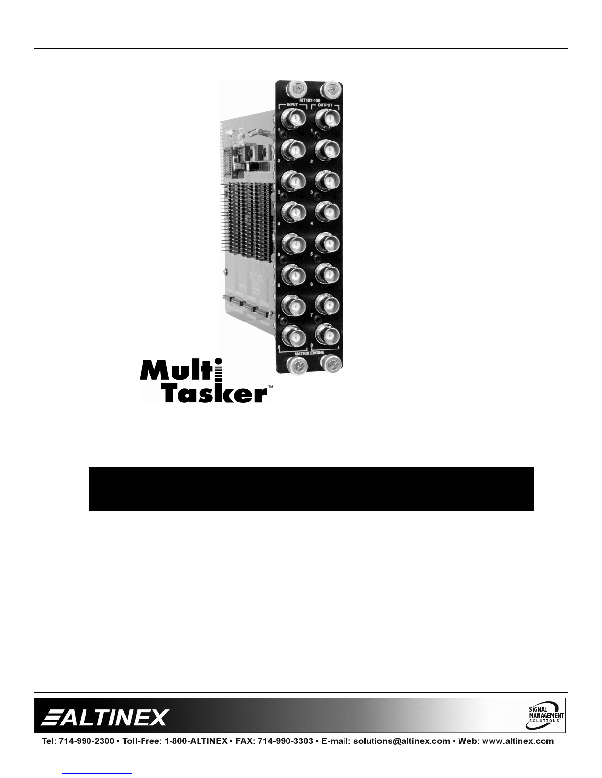
MT107-100
64X64 MATRIX SWITCHER
FOR MULTI-TASKER™
USER’S GUIDE
Page 2

MULTI-TASKER™
TABLE OF CONTENTS
Page
PRECAUTIONS / SAFETY WARNINGS ..............2
GENERAL..........................................................2
INSTALLATION .................................................2
CLEANING.........................................................2
/ CE NOTICE..............................................2
FCC
ABOUT YOUR MT107-100...................................3
TECHNICAL SPECIFICATIONS...........................3
PRODUCT DESCRIPTION ..................................4
APPLICATION DIAGRAM ....................................5
DIAGRAM
DIAGRAM
DIAGRAM
DIAGRAM
1: TYPICAL CONFIGURATION ........5
2: OUTPUT CARD SWITCHES.........6
3: ADD ON CARD SWITCHES..........7
4: INTERNAL VIEW .........................8
INSTALLING YOUR MULTI-TASKER™...............9
OPERATION ........................................................9
RS-232
DESCRIPTION
SUMMARY
CONTROL.............................................9
OF COMMANDS .......................9
OF COMMANDS ...........................17
TROUBLESHOOTING GUIDE ...........................18
IS NOT LIT ...............................................18
LED
IS BLINKING RED ....................................18
LED
DISPLAY....................................................18
NO
ALTINEX POLICY ..............................................19
LIMITED
CONTACT
WARRANTY/RETURN POLICY ........19
INFORMATION..............................19
1
Page 3

MULTI-TASKER™
PRECAUTIONS / SAFETY WARNINGS 1
Please read this manual carefully before using your
MT107-100. Keep this manual handy for future
reference. These safety instructions are to ensure
the long life of your MT107-100 and to prevent fire
and shock hazard. Please read them carefully and
heed all warnings.
1.1 GENERAL
• Qualified ALTINEX service personnel, or their
authorized representatives must perform all
service.
1.2 INSTALLATION
• To prevent fire or shock, do not expose this unit
to rain or moisture. Do not place the MT107-100
in direct sunlight, near heaters or heat radiating
appliances, or near any liquid. Exposure to
direct sunlight, smoke, or steam can harm
internal components.
• Handle the MT107-100 carefully. Dropping or
jarring can damage the card.
• Do not pull the cables that are attached to the
MT107-100.
• Insert the card carefully into the slots of the
Multi-Tasker™ without bending any edges.
• This equipment has been tested and found to
comply with the limits for a Class A digital
device, pursuant to Part 15 of the FCC Rules.
These limits are designed to provide reasonable
protection against harmful interference when the
equipment is operated in a commercial
environment. This equipment generates, uses,
and can radiate radio frequency energy and, if
not installed and used in accordance with the
instruction manual, may cause harmful
interference to radio communications. Operation
of this equipment in a residential area is likely to
cause harmful interference in which case the
user will be required to correct the interference
at his own expense.
• Any changes or modifications to the unit not
expressly approved by ALTINEX, Inc. could void
the user’s authority to operate the equipment.
1.3 CLEANING
• Clean only the connector area with a dry cloth.
Never use strong detergents or solvents, such
as alcohol or thinner. Do not use a wet cloth or
water to clean the card. Do not clean or touch
any component or PCB.
1.4 FCC / CE NOTICE
• This device complies with part 15 of the FCC
Rules. Operation is subject to the following two
conditions: (1) This device may not cause
harmful interference, and (2) this device must
accept any interference received, including
interference that may cause undesired
operation.
2
Page 4
MULTI-TASKER™
ABOUT YOUR MT107-100 2
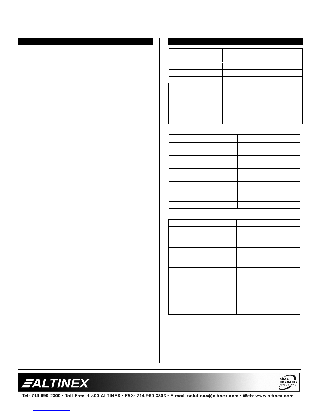
MT107–100
64 X 64 Matrix Engine 300MHz
The MT107-100 is a 64x64 Matrix Engine used for
connecting audio and video signals. The Matrix
Engine has a built-in 8 video inputs and 8 video
outputs. Additional inputs and outputs can be
added using Input and Output video card, which
are mounted to the engine with the specially
provided high bandwidth video cables. Input and
Output connector cards are available for Video
and/or Audio inputs and outputs.
Video Input signals are buffered to the matrix
system through individual Ground Loop Isolation
Amplifiers. The video amplifier can be used for
either video or sync signals.
All control of the Matrix Engine is maintained
through the MultiTasker enclosure.
A video signal detection circuit is present on all
Inputs and Outputs in order to make
troubleshooting easier.
The VIS (Vertical Interval Switching) is a standard
feature on the MT107-100 and can be turned ON
or OFF from RS-232 port.
The Matrix Engine could be easily configured to the
customer requirements by selecting appropriate
number of switching elements. The proper
selection of configuration can be achieved using
MTSetup. The switching elements within the Matrix
Switcher are available in steps of 16. This is
possible through the modular design of the Matrix
Engine with switching elements blocks of 16x16.
The video output option default configuration is for
analog video or sync. A small slide switch is
provided for TTL Sync option.
TECHNICAL SPECIFICATIONS 3
FEATURES/
DESCRIPTION
GENERAL
Inputs
Input Connectors 8 BNC Female
Outputs
Output Connector 8 BNC Female
Compatibility
Signal types
Signal resolution VGA through UXGA
Table 1. MT107-100 General
MECHANICAL MT107-100
Enclosure Slots Required
Base Configuration
Enclosure Slots Required
Add On Cards
Weight 1.1 lb (0.5 kg)
Connector Panel Black Anodized
T° Operating 10°C-50°C
T° Maximum 75°C
Humidity 90% non-condensing
MTBF (calc.) 50,000 hrs
Table 2. MT107-100 Mechanical
ELECTRICAL MT107-100
Video Input Signals
Impedance Analog 75 Ohms
Analog Signal Level 1.5V p-p max.
Sync Input Signals
Impedance 10 kOhm
Signal Level 3 - 5 Volts TTL
Output Video Signals
Impedance Analog 75 Ohms
Gain 1.05
Bandwidth 270 MHz @ -3dB
Output Sync Signals
Impedance 75 Ohms
Signal Level 4.5 Volts TTL
Table 3. MT107-100 Electrical
MT107-100
8
RGBHV,RGBS,RGsB,
Composite Video, Sync
2 Slots
1 Slot per Card
R,G,B
H,V
3
Page 5
MULTI-TASKER™
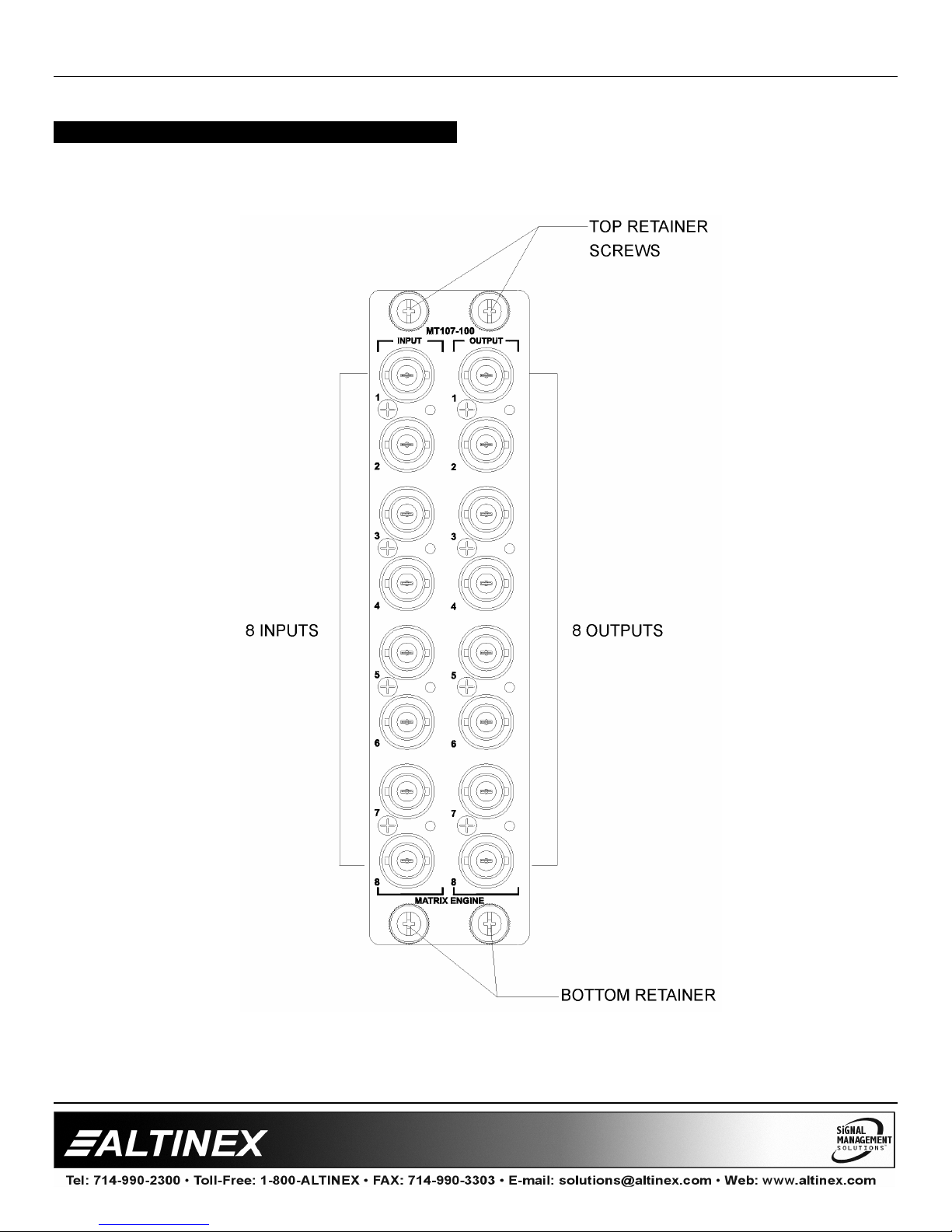
PRODUCT DESCRIPTION 4
4
Page 6
MULTI-TASKER™
APPLICATION DIAGRAM 5
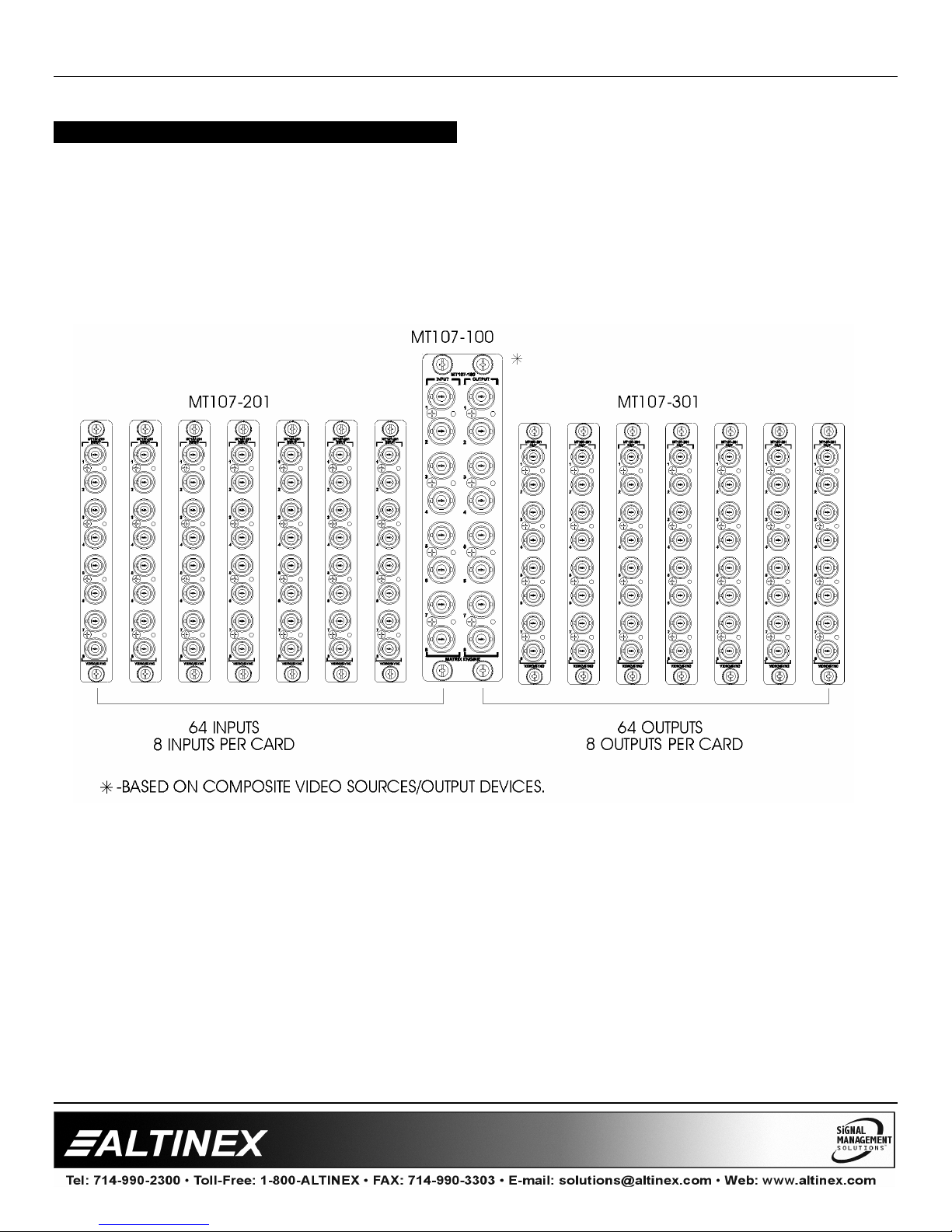
DIAGRAM 1: TYPICAL CONFIGURATION
5
Page 7
MULTI-TASKER™
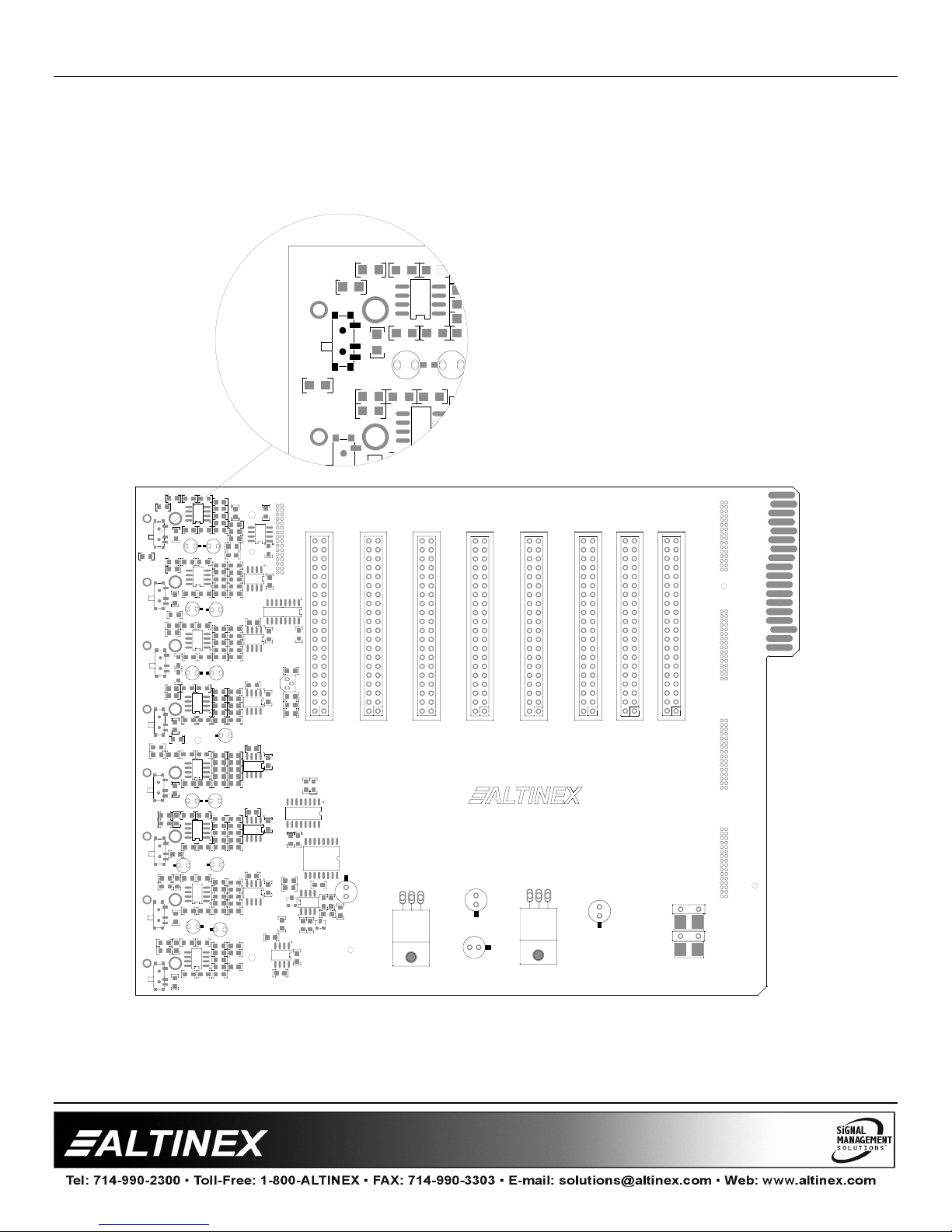
DIAGRAM 2: OUTPUT CARD SWITCHES
VIDEO / SYNC SWITCH SETTINGS
VIDEO
SYNC
VIDEO
SYNC
VIDEO
VIDEO
VIDEO
VIDEO
VIDEO
VIDEO
SYNC
SYNC
SYNC
SYNC
VIDEO
SYNC
R78
R1
R60
SW5
R61
R3
R62
C1
R17
U1
Set the VIDEO/SYNC switch to match
the type of output signal being used.
R1
C18
C2
C
9
7
C
9
9
C3
R19
U2
NOTE: There are eight (8) switches,
C34
one per output.
SW6
VIDEO
R1
C1
R17
R60
SW5
R3
R78
R62
SW6
SYNC
R81
R5
R83
SW8
R84
SYNC
R79
R7
R65
SW7
R58
R93
SW1
R77
R95
SW4
C86
R75
R97
SW2
R76
R99
SW3
C17
R2
U1
R33
R18
C18
C2
7
9
C
C34
R61
9
9
C
C3
R19
C19
U2
R34
R20
C4
C20
C38
C98
R63
C5
R21
C21
U3
R35
R22
C22
C36
C6
8
8
C
C7
R23
C23
U4
R36
R24
C40
C24
C8
R66
R80
R25
C11
C25
R9
U5
R37
R26
C10
C26
C42
R94
C90
R11
R27
C9
C27
U6
R38 R12
R28
R96
C12
C46C28
R13
R29
C13
C29
R39
R48
U7
R30
C30
C44
C14
C91
R98
R15
C15
R31
C31
R40
R50
R32
C32
C48
C16
U8
R100
C59
+5V
+5V
+5V
U
9
R43
R67
C33
R59
C49
C50
U10
C65
R4
R68
R45
C37
R52
C96
U11
C61
R6
R69
R44
C35
R57
C87
C63
R8
R70
R46
C39
R54
C92
C67
R10
R71
R47
C41
R88
C95
U14
C69
R72
R49
C45
R86
C94
U15
C73
R14
R73
C43
R92
C93
R74
R16
C47
GND
GND
1-8
-5V
-5V
-5V
GND
GND
0
6
C
GND
A0
A1
A2
C66
U24
C51
C62
C85
+13V
C57
+6V
C52
C53
C54
C55
I
G
C64
O
1
U
7
C58
R64
R56
U12
C68
U13
C70
C74
U16
P25
C80
C101
C
C
1
7
0
7
0
C76
C81
R53
D2
U19
C56
R42
D1
C83
C71
C72
R90
8
1 9
+13V
+6V
-6V
-13V
U20
U21
C79
1
4
5
8
R
C
R41
R55
9-16
P26
17-24
16
+13V
+6V
-6V
-13V
P27
U18
I
-5v
G
24
17
+13V
+6V
-6V
-13V
25-32
P28 P29
C82
C75
26-40
32
25
+13V
+6V +6V
-6V
-13V
1-800-ALTINEX
www.altinex.com
285-0420-002
OUTPUT CARD
U22
+5V
41-48
40
33
+13V
-6V
-13V
48
41
+13V
+6V
-6V
-13V
P30
I
C78
57-64
42-56
P31
64
56
57
49
+13V
+13V
+6V
+6V
-6V
-6V
-13V
-13V
P32
OUT64
OUT63
OUT62
OUT61
OUT60
OUT59
OUT58
OUT57
OUT56
OUT55
OUT54
OUT53
OUT52
OUT51
OUT50
OUT49
OUT48
OUT47
OUT46
OUT45
OUT44
OUT43
OUT42
OUT41
OUT40
OUT39
OUT38
OUT37
OUT36
OUT35
OUT34
OUT33
OUT32
OUT31
OUT30
OUT29
OUT28
OUT27
OUT26
OUT25
OUT24
OUT23
OUT22
OUT21
OUT20
OUT19
OUT18
OUT17
OUT16
OUT15
OUT14
OUT13
OUT12
OUT11
OUT10
OUT9
OUT8 GND
OUT7
OUT6
OUT5
OUT4
OUT3
OUT2
OUT1
F5
F4
3
F
F1
GND
GND
GND
GND
GND
GND
GND
GND
GND
GND
GND
GND
GND
GND
GND
GND
GND
GND
GND
GND
GND
GND
GND
GND
GND
GND
GND
GND
GND
GND
GND
GND
GND
GND
GND
GND
GND
GND
GND
GND
GND
GND
GND
GND
GND
GND
GND
GND
GND
GND
GND
GND
GND
GND
GND
GND
GND
GND
GND
GND
GND
GND
GND
6
Page 8
MULTI-TASKER™
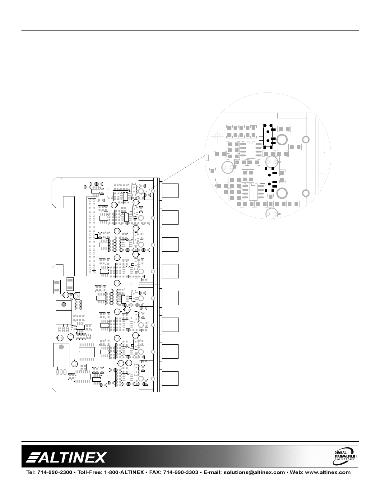
DIAGRAM 3: ADD ON CARD SWITCHES
VIDEO / SYNC SWITCH SETTINGS
Set the V/S (Video/Sync) switch to
match the type of output signal being
R17
P1
8
SW5
1
C
R61
S
V
R1
S
0
2
C
V
U2
R19
R78
R60
C99
R63
SW6
R3
R62
R81
used.
NOTE: There are eight (8) switches,
one per each output.
ALTINEX, INC
285-0423-002
F4
F1
8
C
7
U22
I
+5V
7
5
C
G
I -5V
G
3
C60
3
9
4
C
9
5
C
U9
P3
1
U17
C57
I
G
O
C58
U13
R64
R56
3
4
5
6
8
5
5
7
C
R
R
C
U19
1
1
D2
5
8
R
C
D1
1
3
2
4
8
4
R
C
R
C82
U18
U21
C79
1
7
C85
C
C77
0
0
0
1
8
C
C
U20
U16
C
R
6
7
R43
R33
R2
C17
R59
5
6
0
6
5
6
C
C
C
C87
C37
R68
R4
U10
R52
2
1
1
6
5
6
C
C
C
C96
C35
R69
R6
U11
R57
4
2
3
6
5
6
C
C
C
C95
C39
R70
R8
U12
R54
C94
8
3
7
6
5
6
C
C
C
R26
C41 C42
R47
R71
R37
R10
C9
R88
0
4
9
7
5
6
C
C
C
C97
C45
R72
R12
U14
R86
4
5
3
7
5
7
C
C
C
C92
C43
R73
R14
U15
R92
2
6
7
5
C93
C
C
C47
R74
R90
P1
8
8
4
SW5
1
1
3
2
R
C
C
C
R61
S
U1
V
R78
R60
R1
C99
R17
C1
S
0
4
2
R20
C38
R45
R34
C19
C3
6
C
R22
C36
R44
R35
C5
C21
8
C
R24
C40
R46
R36
C23
C7
C26
C10
C25
C98
2
1
C
R28
C46
R49
R38
C11
C27
4
1
C
R30
C44
R48
R39
9
1
C
C13
C29
R32
C48
R50
R40
R16
C15
C31
C
2
2
C
U5
6
1
C
C
V
U2
R19
SW7
S
V
U3
R21R5R83
4
2
C
S
V
U4
R23
S
V
R25
S
8
2
C
V
U6
R27
0
3
C
S
V
U7
R29
S
2
3
C
V
U8
R31
R63
SW6
R3
R62
R81
C90
R
8
4
R79
C89
SW8
R66
R65
R7
R80
R94
SW1
R93
R9
SW4
R58
R96
R77
R95
R11
C86
SW2
R98
R97
R13
SW3
R75
R100
R99
R76
R15
P2
8
3
4
1
3
3
2
R
C
C
C
R20
C38
R45
U1
C1
4
C
R43
R33
R2
C17
6
6
C
C87
C37
R68
R34
C3
S = SYNC
V = VIDEO
7
Page 9
MULTI-TASKER™
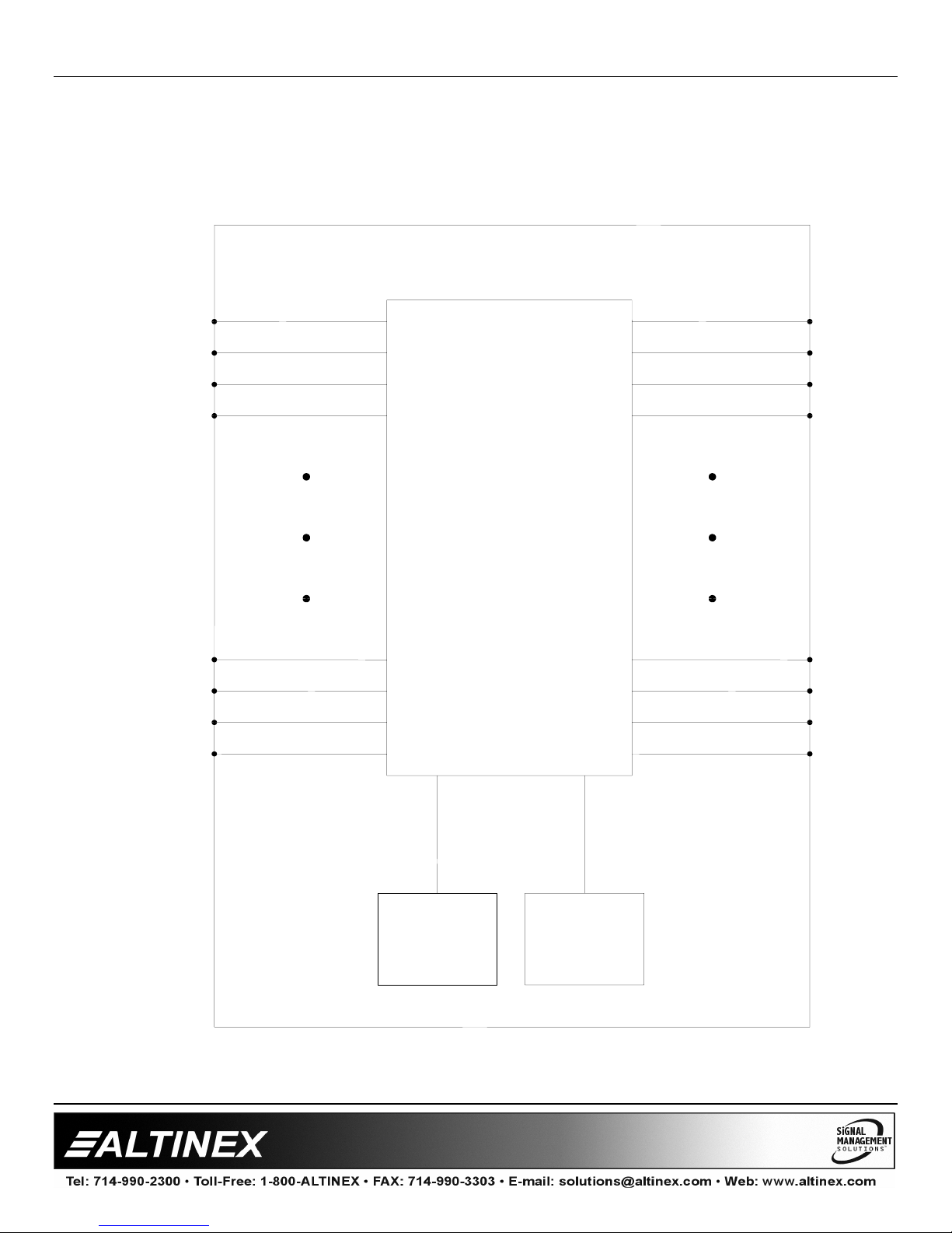
DIAGRAM 4: INTERNAL VIEW
IDC IDC
MT107-100, 64X64 MATRIX ENGINE
IN1
IN2
IN3
IN4
64X64 MATRIX
OUT1
OUT2
OUT3
OUT4
IN61
IN62
IN63
IN64
MAIN
MP
OUT61
OUT62
OUT63
OUT64
POWER
SUPPLY
8
Page 10
MULTI-TASKER™
INSTALLING YOUR MULTI-TASKER™ 6
Step 1. Decide what type of output signal is
required for each output. (Video or Sync)
Step 2. Set the jumpers on the output card(s) as
necessary. See DIAGRAM 2 and
DIAGRAM 3 for switch locations.
Step 3. Determine the number of slots required
for the MT107-100, including the add-on
cards. The base MT107-100 requires two
slots, and a fully loaded 64X64 Matrix
engine requires 16 slots.
Step 4. Carefully, slide the MT107-100 into
available slots in the Multi-Tasker™
Enclosure in order to connect to the bus.
Make sure that the MT107-100 cards fits
into place.
Step 6. Secure the cards to the Multi-Tasker™ by
tightening the retainer screws located on
the top and bottom of each card.
Step 7. Connect a cable from the video source to
one of the input connectors on the
MT107-100 and one of the output
connectors to a display device through a
cable.
1. Square brackets “[ ]” are part of the
command.
2. Use uppercase letters for all commands.
Commands that end in "S" will be saved into
memory. Commands not ending in "S" will still
be executed but will not be restored when the
system is reset or powered off and then power
on.
7.2 DESCRIPTION OF COMMANDS
Each command consists of three parts:
Function, Card ID, and Unit ID.
[ Function , Card ID , Unit ID ]
Example: [VERC3U2]
VER = Function
C3 = Card or Group ID
U2 = Unit ID
For Function, see a detailed explanation under
each command description.
The Card ID is an assigned value. It is equal to
the enclosure slot number in which the card is
installed. The value can range from 1 to 4 up to
1 to 20 depending on the enclosure.
Step 8. Starting from the left, identify the slot
number where the MT107-100 INPUT
CONNECTOR CARD is plugged into the
Enclosure (left slot of the Engine). Make
note of the slot number. It is required for
RS-232 control.
OPERATION 7
7.1 RS-232 CONTROL
When used in the Multi-Tasker™ Enclosure, the
MT107-100 has many advanced remote control
capabilities, which are accessible through
standard RS-232 communication. The actual
controlling can be accomplished through a
computer control system or any other device
capable of sending RS-232 commands.
7.1.1 RS-232 INTERFACE
The RS-232 commands, for the MT107-100, are
in a simple ASCII character format.
9
Card ID 0 (C0) is used for the controller. See
the MT100-100 User’s Guide for details.
The Group ID is a number representing a group
of cards defined with the [WR] command. When
using the Group ID, all cards in the group will
perform the given instruction.
Changing the position of a card will significantly
affect the commands recorded on software
definitions or third party control systems.
The Unit ID has a value from 0 to 9. Unit ID 0
should be used for single unit operation. If the
Unit ID is set to zero, each command may be
used without Ui. Use the command [SETU0],
as explained in the MT100-100 User’s Guide.
Example:
[VERC3]: For Unit ID Zero
[VERC3Ui]: For Unit ID other than Zero
Page 11

MULTI-TASKER™
[VERC3]: Equivalent to [VERC3U0]
1. [VER]
This command displays the firmware version
and card type for the MT107-100 card.
Command Format: [VERCnUi]
Cn = Engine Card Slot Number
Ui = Unit ID (i = # from 0 to 9)
Example:
There is an MT107-100 card is in slot #2. Send
the command
Enclosure will return feedback as:
MT107-100 690-0159-003
MT107-100 = the card model
690-0159-003 = the software version
2. [C]
This command displays the active matrix
configuration settings.
Command Format: [CnUi]
Cn = Engine Card Slot Number
Ui = unit ID (i = # from 0 to 9)
Example:
An MT107-100 in slot #7. When sending the
command [C7], feedback will be returned as:
Matrix number:1
Matrix size:64X64
Input offset:00
Output offset:00
Channel width:01
Channel space:00
Ch1 In1 Out1 ON AudioL32
Ch1 In2 Out2 ON AudioL32
…
Ch1 In63 Out63 ON AudioL32
Ch1 In64 Out64 ON AudioL32
Description of Feedback:
The first line lists the matrix number, 1 to 9. The
next five lines describe the properties of the
matrix. The remaining lines are channel specific.
[VERC2] and the Multi-Tasker™
Matrix 1 is the active matrix. Matrix 1 is a 64X64
matrix with no input offset and no output offset.
The channel width is one and the channel
spacing is zero. All 64 channels are ON, the
input audio level is set to the maximum of 32
and each input is connected to its
corresponding output.
3. [MAT]
This command sets the matrix configuration for
the matrix engine.
Command Format:
[MATj,mm,ww,xx,yy,kk,ll,CnUiS]
j = Matrix ID (j = # from 1 to 9)
The following properties MUST
two (2) digit format.
mm = Inputs (2 digit # from 01-64)
zz = Outputs (2 digit # from 01-64)
xx = Input Offset (2 digit # from 00-99)
yy = Output Offset (2 digit # from 00-99
kk = Channel Width (2 digit # from 01-32)
ll = Channel Spacing (2 digit # from 00-31)
Cn = Engine Card Slot Number
(The slot number of the LEFT card of the
engine is the Engine Card Slot number.)
Ui = Unit ID (i = # from 0 to 9)
S = Save
This property saves the configuration to
Matrix ID memory and will allow the
configuration to be recalled any time,
even after power up or reset.
Adding the 'S' to the command will also
make the matrix configuration the default
at power up. The last configuration ID
created and saved will be the default at
power up.
In order to change the power up default
without having to redefine the settings,
see the command [MjCnS].
Matrix Configuration Definitions:
1. Matrix ID:
may be defined in a single engine. Once
saved, the configuration may be recalled by
number without having to redefine the
settings.
A total of 9 matrix configurations
be entered in
10
Page 12
MULTI-TASKER™
2. Number of Inputs: The number of inputs in
the configuration, or eight times the number
of input cards installed is the maximum.
If the channel width and spacing are
different, then the number of inputs will be
lower. For example, in a 32X32 matrix with
a width of 4 and a spacing of 7, the number
of inputs would be 8. See Example 1 in this
section for specifics.
3. Number of Outputs:
4. Input Offset:
The offset defines where Input
Same as for Inputs.
#1 will be in reference to Input #1 on the
Input Connector Card. Typically, Input #1
would be Input #1 of the base card.
However, an offset of 8 will make Input #1
start at the actual Input #9.
5. Output Offset:
6. Channel Width:
Same as for Input Offset.
The number of signals per
channel. The default width is one.
7. Channel Spacing:
The default spacing is
zero. When dealing with multi-cabled
signals, the spacing is typically one less
than the number of inputs on a single card.
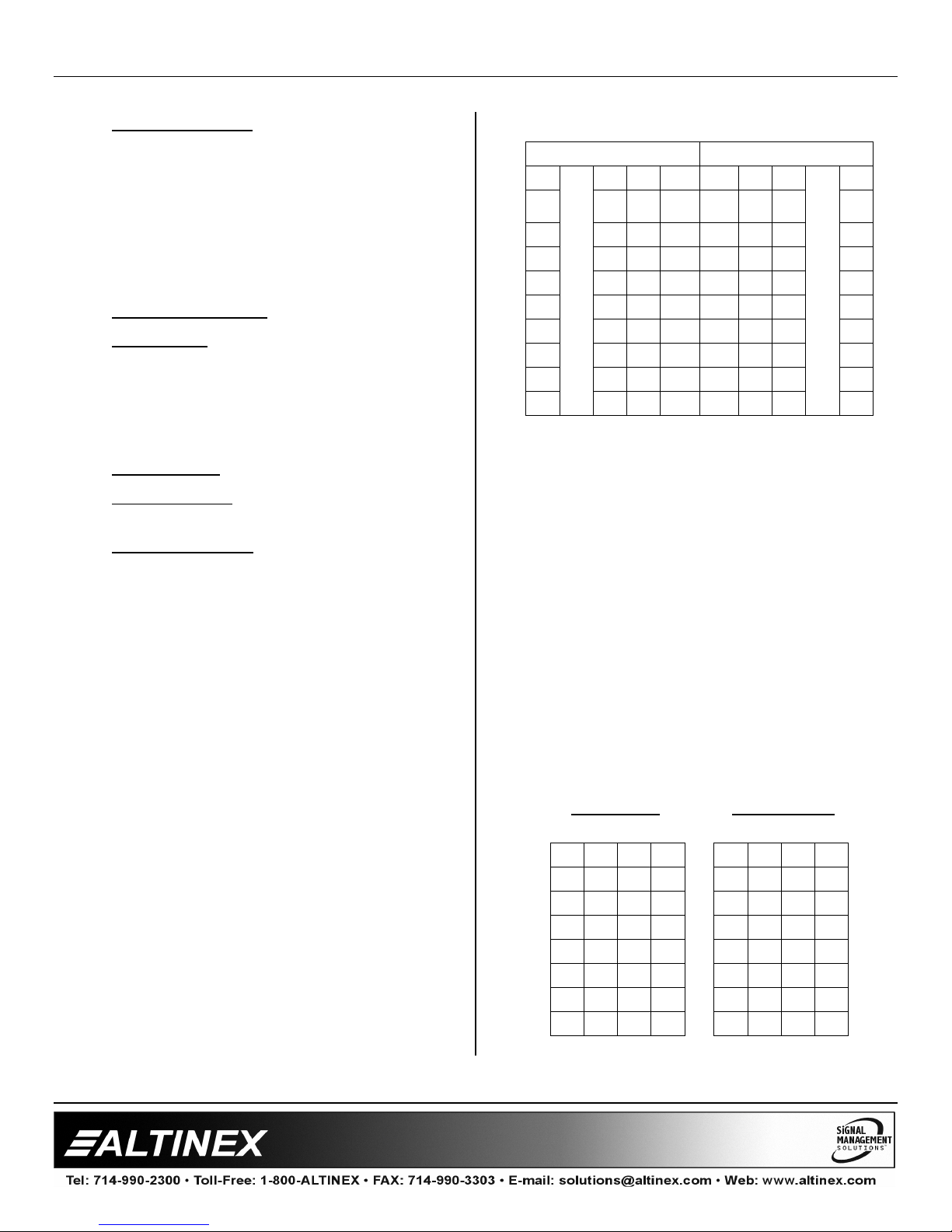
Matrix Assembly Layout:
Input cards count from the main Input
Connector Card, RIGHT to LEFT.
Output cards count from the main Output
Connector Card, LEFT to RIGHT.
The following table illustrates the card and
channel numbering. The channel numbering is
based upon the default configuration. The
default configuration is configured as a 64X64
Matrix with the following settings:
Number of Inputs = 64
Number of Outputs = 64
Input Offset = 00
Output Offset = 00
Channel Width = 01
Channel Spacing = 00
Default Configuration
INPUT CARDS OUTPUT CARDS
8 … 3 2 1 1 2 3 … 8
AddOn AddOnAddOnBase
57
58
59
60
61
62
63
64
17 9 1 1 9 17 57
18 10 2 2 10 18 58
!
19 11 3 3 11 19
20 12 4 4 12 20 60
21 13 5 5 13 21 61
22 14 6 6 14 22 62
23 15 7 7 15 23 63
24 16 8 8 16 24 64
Unit
Base
Unit
AddOnAdd
On
"
Add
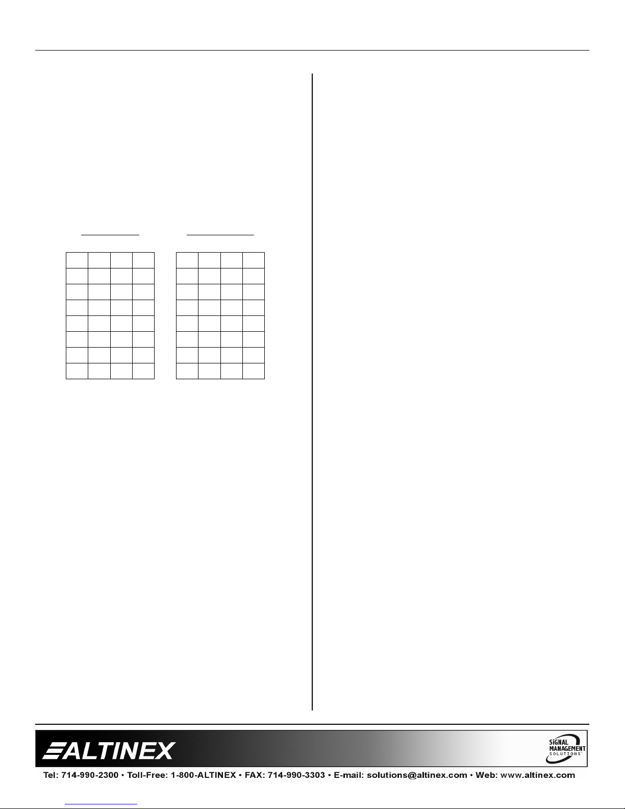
Example 1:
Inputs = 08
Outputs = 08
Input Offset = 00
Output Offset = 00
Width = 04
Spacing = 07
In the charts below, the cards are in groups of
four to help illustrate the CHANNEL WIDTH
definition.
In this configuration, if Input 1 is connected to
Output 8, the entire channel, 1a, 1b, 1c and 1d,
will be switched to outputs 8a, 8b, 8c and 8d
respectively.
Input Cards
Output Cards
4 3 2 1 1 2 3 4
1d 1c 1b 1a 1a 1b 1c 1d
2d 2c 2b 2a 2a 2b 2c 2d
3d 3c 3b 3a 3a 3b 3c 3d
4d 4c 4b 4a 4a 4b 4c 4d
5d 5c 5b 5a 5a 5b 5c 5d
6d 6c 6b 6a 6a 6b 6c 6d
7d 7c 7b 7a 7a 7b 7c 7d
8d 8c 8b 8a 8a 8b 8c 8d
On
59
11
Page 13
MULTI-TASKER™
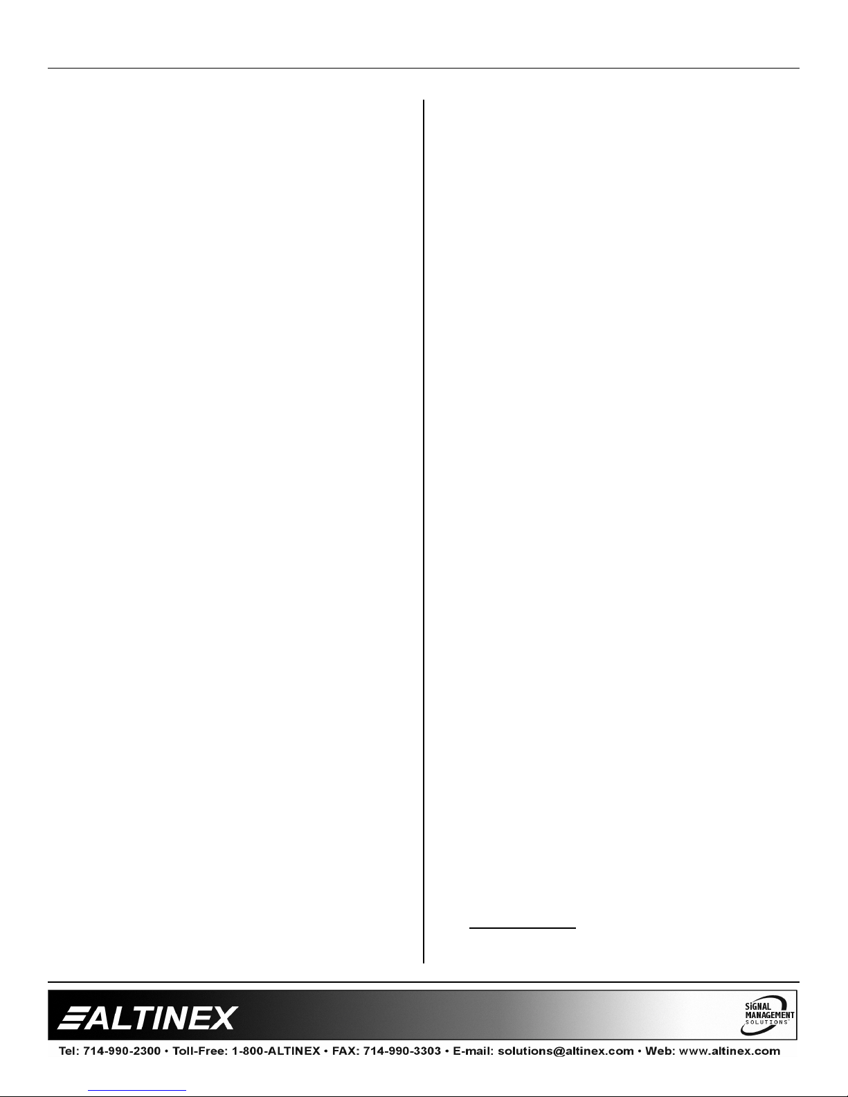
Example 2:
Inputs = 16
Outputs = 16
Input Offset = 00
Output Offset = 00
Width = 02
Spacing = 00
In this configuration, if Input 1 is connected to
Output 16, the entire channel, 1a and 1b, will be
switched to outputs 16a and 16b respectively.
Input Cards
Output Cards
4 3 2 1 1 2 3 4
13a 9a 5a 1a
13b 9b 5b 1b
14a 10a 6a 2a
14b 10b 6b 2b
15a 11a 7a 3a
15b 11b 7b 3b
16a 12a 8a 4a
16b 12b 8b 4b
1a 5a 9a 13a
1b 5b 9b 13b
2a 6a 10a 14a
2b 6b 10b 14b
3a 7a 11a 15a
3b 7b 11b 15b
4a 8a 12a 16a
4b 8b 12b 16b
4. [MjCn]
This command selects the matrix to be active.
Command Format: [MjCnUi]
j = Matrix ID (j = # from 1 to 9)
Cn = Engine Card Slot Number
Ui = Unit ID (i = # from 0 to 9)
Example:
There is a matrix engine in slot 6. Send the
command [M1C6] to recall matrix configuration
#1 of card 6.
5. [MjCnS]
This command will save the defined matrix
number as the default, which would be recalled
on power up or reset. The matrix settings MUST
first be saved when the matrix is defined using
the [MAT…S] command
Command Format: [MjCnUiS]
j = Matrix ID (j = # from 1 to 9)
Cn = Engine Card Slot Number
Ui = Unit ID (i = # from 0 to 9)
S = Save
Example:
In order to make configuration #1 of card 6 the
default configuration when power is turned on,
send the command [M1C6S].
6. [ON]
This command turns ON a single output, or all
the outputs, for the current matrix.
Command Format: [ONzzCnUi]
zz = Output Number (zz = # from 01 to 64)
Cn = Engine Card Slot Number
Ui = Unit ID (i = # from 0 to 9)
Example 1: SINGLE OUTPUT
There is an MT107-100 in slot #10. Turn ON
output number 64 by sending the command
[ON64C10].
Example 2: ALL OUTPUTS
There is an MT107-100 in slot #10. Turn ON
ALL outputs by sending the command [ONC10].
7. [OFF]
This command turns OFF a single output, or all
outputs, for the current matrix.
Command Format: [OFFzzCnUi]
zz = Output Number (zz = # from 01 to 64)
Cn = Engine Card Slot Number
Ui = Unit ID (i = # from 0 to 9)
Example 1: SINGLE OUTPUT
There is an MT107-100 in slot #10. Turn OFF
only output number 01 by sending the command
[OFF01C10].
Example 2: ALL OUTPUTS
There is an MT107-100 in slot #10. Turn OFF
ALL outputs by sending the command
[OFFC10 ].
12
Page 14

MULTI-TASKER™
8. [IO]
This command connects an input to an output
for the current matrix configuration.
Command Format: [ImmOzzCnUi]
mm = Input (2 digit # from 01 to 64)
zz = Output (2 digit # from 01 to 64)
Cn = Engine Card Slot Number
Ui = Unit ID (i = # from 0 to 9)
Example:
Connect Input 22 to Output 32 of the engine in
slot #10. Send the command [I22O32C10] and
Input 22 will be connected to Output 32.
9. [IO✻✻✻✻]
This command connects a single input to all the
outputs for the current matrix configuration.
Command Format: [ImmO✻CnUi]
mm = Input (2 digit # from 01 to 64)
Cn = Engine Card Slot Number
Ui = Unit ID (i = # from 0 to 9)
Example:
Connect Input 07 of the engine in slot #8 to all
the outputs for that engine in its current matrix
configuration. To do this, send the command
[I07O✻C8].
10. [IN#S]
This command returns a list of outputs that are
connected to a specified input.
Command Format: [INmSCnUi]
mm = Input (2 digit # from 01 to 64)
Cn = Engine Card Slot Number
Ui = Unit ID (i = # from 0 to 9)
11. [OUT#S]
This command returns the input that is
connected to the specified output.
Command Format: [OUTmSCnUi]
mm = Output (2 digit # from 01 to 64)
Cn = Engine Card Slot Number
Ui = Unit ID (i = # from 0 to 9)
Example:
A matrix engine is in slot #9 and input 8 is
connected to output 24. Send the command
[OUT24SC9] and receive the following
feedback:
8
12. [MODE]
This command sets the matrix switch mode to
Blocking or Non-Blocking.
Command Format: [MODEmCnUi]
m = 1 = ON, 0 = OFF
Cn = Engine Card Slot Number
Ui = Unit ID (i = # from 0 to 9)
Example: NON-BLOCKING
Send the command [MODE0C9] to turn OFF
matrix switch blocking for the engine in slot #9.
Next, send the command [I1O*C9] to connect
input 1 to all outputs. In Non-Blocking mode, the
inputs will be switched and the outputs will be
enabled.
Example: BLOCKING ON
Send the command [I1O*C9] to connect input 1
to all outputs. With Blocking ON, input 1 will be
connected to all outputs, but only output 1 will
be enabled. The remaining outputs will need to
be enabled using the [ON] command.
Example:
A matrix engine is in slot #10 and input 22 is
connected to outputs 1, 32 and 64. Send the
command [IN22SC10] and receive the following
feedback:
[1,32,64]
Connecting a single output will result in the
output being switched and enabled. For
example, with Blocking ON, sending the
command [I22O22C9] will result in Input 22
being connected to Output 22 and Output 22 will
be enabled.
13
Page 15
MULTI-TASKER™
13. […S] – Save
This command will save the configuration
command being sent in memory. When
sending the command [I1O8C4S], after reset or
power up, Input 1 will be connected to Output 8
of the Engine Card Slot #4.
14. […P] – Path
This command will set the path for the output,
but it is not active until the switch command,
[SW], is executed. Commands ending in "P" are
not executed immediately. The path for outputs
on multiple cards or the same card can be
preset
Example 1:
There is a Matrix Engine slot #9. To enable
outputs 1 and 2 simultaneously, use the
following commands:
[ON1C9P]
[ON2C9P]
[SW]
Example 2:
There is a Matrix Engine in slot#9 and one
regular video switcher in slot #1. Connect Input
1 of the Engine Card in slot #9 to Output 64
while simultaneously disabling the outputs for
the card in slot #1. In order to accomplish this,
send the following commands:
Command Format: [SELmmCnUi]
mm = Input (2 digit # from 01 to 64)
Cn = Engine Card Slot Number
Ui = Unit ID (i = # from 0 to 9)
[+] = Increment level by one
[–] = Decrement level by one
Example:
The Engine Card is in slot #8. Adjust the volume
on Input 2. The current volume level is set to 10.
After sending the following commands, a better
volume level of 15 is obtained:
1. [SEL02C8]
The current volume level is 10.
2. [ – ] [ – ] [ – ]
The level is now 7 and is too quiet.
3. [ + ] [ + ] [ + ] [ + ] [ + ] [ + ] [ + ] [ + ]
The level is now 15 and no further
adjustments are required.
17. [VOL]
This command sets the absolute volume level
for a given input.
Command Format: [VOLmmAvCnUi]
mm = Input (2 digit # from 01 to 64)
Av = Volume Level (# from 01 to 32)
Cn = Engine Card Slot Number
[IN1O64C9 P]
[OFFC1P]
[SW]
15. [SW] – Switch
The switch command immediately connects
inputs and outputs, which were previously set
with the PATH command on this card or any
other cards in the MT100-100. See the PATH
command for examples.
16. [SEL] with [ + ] and [ – ]
This command is the volume select command. It
sets the path to adjust the input volume level of
the current matrix and is used in conjunction
with the [+] and [–] commands.
14
Ui = Unit ID (i = # from 0 to 9)
Example:
Set the volume level for Input 20, of the Engine
Card in slot #8, to a level of 16 using the
command [VOL20A16C8].
18. [SDI]
This command is used to detect if there is a
signal present on one input or all inputs. The
system will return feedback along the following:
In1 Signal ON = YES a signal is present.
or
In1 Signal OFF = NO, there is no signal.
SINGLE INPUT
Command Format: [SDImmCnUi]
Page 16

MULTI-TASKER™
mm = Input (2 digit # from 01 to 64)
Cn = Engine Card Slot Number
Ui = Unit ID (i = # from 0 to 9)
Example: CHECK ONE INPUT
Check for a signal on Input 1 of the Engine in
slot #8 by sending the command [SDI01C8]. If
there is a signal present on Input 1, the system
will return the following feedback:
In1 Signal ON
ALL INPUTS
Command Format: [SDICnUi]
Cn = Engine Card Slot Number
Ui = Unit ID (i = # from 0 to 9)
Example: CHECK ALL INPUTS
Check for a signal on all inputs of the Engine in
slot #8 by sending the command [SDIC8]. In this
case, there is a signal on Input 1, but the rest
have no signals. The system will return the
following feedback:
In1 Signal ON
In2 Signal OFF
In3 Signal OFF
In4 Signal OFF
…
In63 Signal OFF
In64 Signal OFF
19. [SDO]
This command is used to detect if there is a
signal present on one output or all outputs. The
system will return feedback along the following:
Out1 Signal ON = YES a signal is present.
or
Out1 Signal OFF = NO, there is no signal.
SINGLE OUTPUT
Command Format: [SDOmmCnUi]
mm = Output (2 digit # from 01 to 64)
Cn = Engine Card Slot Number
Ui = Unit ID (i = # from 0 to 9)
Example: CHECK ONE OUTPUT
15
Check for a signal on Output 1 of the Engine in
slot #8 by sending the command [SDO01C8 ]. If
a signal present on Output 1, the following
feedback will be returned:
Out1 Signal ON
ALL OUTPUTS
Command Format: [SDOCnUi]
Cn = Engine Card Slot Number
Ui = Unit ID (i = # from 0 to 9)
Example: CHECK ALL OUTPUTS
Check for a signal on all outputs of the Engine
in slot #8 by sending the command [SDOC8]. In
this case, there is a signal present on Output 1,
but the rest have no signals. The system will
return the following feedback:
Out1 Signal ON
Out2 Signal OFF
Out3 Signal OFF
Out4 Signal OFF
…
Out63 Signal OFF
Out64 Signal OFF
20. [VIS]
This command activates and deactivates the
VIS feature.
If the VIS feature is active, and no switching
pulse is present within 20mS, switching will be
performed on a regular basis.
Command Format: [VIS=pCnUi]
p = Variable for activation/deactivation of VIS
0 = VIS is turned OFF
1 = VIS is turned ON
Cn = Engine Card Slot Number
Ui = Unit ID (i = # from 0 to 9)
Example:
Turn OFF the VIS for the Engine Card in
slot #8. Send the command [VIS=0C8]. Then
check the status of the VIS circuit with the next
command [TVIS].
Page 17

MULTI-TASKER™
21. [TVIS]
This command is used to test if the VIS circuit is
ON or OFF.
Command Format: [TVISCnUi]
Cn = Engine Card Slot Number
Ui = Unit ID (i = # from 0 to 9)
Example:
Test the VIS circuit for the Engine Card in
slot #8. Send the command [TVISC8] and the
system will return the following feedback:
VIS circuit ON
22. [CLR]
This command resets the MT107-100 to the
manufacturer's settings. The matrix
configuration is set to Matrix 1, but the matrix
definitions are not cleared using this command.
Command Format: [CLRCnUi]
Cn = Engine Card Slot Number
Ui = Unit ID (i = # from 0 to 9)
This command displays information available for
the Multi-Tasker interface commands.
Command Format: [HELPCnUi]
Cn = Engine Card Slot Number
Ui = Unit ID (i = # from 0 to 9)
Example:
In order to display the RS-232 commands
available for the MT107-100 card in slot 2, send
the command [HELPC2]. The commands along
with a brief description will be displayed in the
Terminal Window.
25. [WR]
This command groups multiple cards in the
Enclosure. Each unit contains a maximum of
eight groups.
In Multi-Tasker™ systems with audio and video
cards, boards are typically grouped as follows:
Group 1 = Video Cards
Group 2 = Audio Cards
Group 3 = Video and Audio Cards
Example:
Clear the MT107-100 with Engine Card in slot
#12. To do this, send the command [CLRC12].
The system will return the following feedback
immediately:
PLEASE WAIT
CARD IS PERFORMING FACTORY RESET
IT WILL TAKE COUPLE OF MINUTES
Upon completion, the following will be displayed.
FACTORY RESET COMPLETED
23. [TEST]
This command performs a series of internal
tests on the matrix engine memory.
Upon completion, the system will display the
results. This feedback will be similar to the
following example:
MEMORY IC TEST RESULTS:
MEMORY IC PASS
24. [HELP]
If assigning group commands to button
functions, it is best to use the "Press and Hold
on Power Up" to make group settings.
Command Format: [WRCn…GkUi]
Cn = Card ID (n = slot # from 1 to max slots)
Gk = Group number (k = # from 1-8)
Ui = Unit ID (i = # from 0-9)
Example:
To group cards 1, 2, and 3 as group 5 of
Unit ID 1, send the command
[WRC1C2C3G5U1]. After executing this
command, cards 1, 2 and 3 will be grouped
together as group 5 of Unit ID 1.
16
Page 18

MULTI-TASKER™
26. [CLR]
This command clears the members for a single
group or for all eight groups. The clear
command restores the cards to default settings.
Command Format: [CLRGkUi]
Gk = Group number (k = # from 1-8)
Ui = Unit ID (i = # from 0-9)
Example:
1) To clear group 1, send the [CLRG1U1]
command. This command clears the
members for the specified group only.
2) To clear all groups of Unit ID 1, send the
[CLRG✻U1] command.
27. [RD]
This command displays the members in each
group.
Command Format: [RDGkUi]
Gk = Group number (k = # from 1-8)
Ui = Unit ID (i = # from 0-9)
Example:
The cards in slots 1, 2 and 19 are part of
group 5 in Unit ID 1. Read the member data for
group 5 of Unit ID 1, by sending the command
[RDG5U1]. The system will return feedback as
follows:
C1C2C19 G5U1
C1 = Card in Slot 1
C2 = Card in Slot 2
C19 = Card in slot 19
G5 = Group 5
U1 = Unit ID 1
28. [CLM]
This command removes the members in a
group and leaves the group empty.
Command Format: [CLMGkUi]
Gk = Group number (k = # from 1-8)
Ui = Unit ID (i = # from 0-9)
Example:
Group 5 of Unit ID 1 contains the cards in slots
1, 2 and 19. Read the member data for group 5
of Unit ID 1. Send the command [RDG5U1] and
receive the following feedback:
C1C2C19 G5U1
Now, clear group 5 by sending the command
[CLMG5U1]. Reread the member data as above
and note the following feedback:
NONE G5U1
7.3 SUMMARY OF COMMANDS
1) [VER] Receives software version
2) [C] Receives status of the card
3) [MAT] Matrix Configuration
4) [MC] Select matrix to be active
5) [MCS] Save matrix configuration
6) [ON] Turns on one or more outputs for
a single card or a group of cards
7) [OFF] Turns off one or more outputs for
a single card or a group of cards
8) [IO] Connect one input to one output
9) [IO✻✻✻✻] Connect one input to all outputs
10) [IN#S] Receive status of one input
OUT#S] Receive status of one output
11) [
12) [
MODE] Turn Blocking On/Off
13) […S] Save the command configuration
sent
14) […P] Sets the path, preload for [SW]
15) [SW] Switch (outputs the preloaded
buffer)
16) [SEL] Select input to adjust volume
17) [VOL] Set the desired absolute volume
18) [SDI] Input Signal Present
19) [SDO] Output Signal Present
20) [VIS] Activate/deactivate VIS feature
17
Page 19

MULTI-TASKER™
21) [TVIS] Test the VIS circuit
22) [CLR] Reset to manufacturer settings
23) [TEST] Perform internal tests
24) [HELP] Display all available commands
Group Commands
25) [WR] Groups multiple cards
26) [CLR] Clears members of a single
group or all groups
27) [RD] Displays group members
28) [CLM] Removes members from group.
TROUBLESHOOTING GUIDE 8
We have carefully tested and have found no
problems in the supplied MT107-100. However, we
would like to offer suggestions for the following:
8.1 LED IS NOT LIT
Cause 1: Card cage is not plugged in.
Solution: Plug card cage in. If the LED lights,
the problem is solved. If the LED is
still not ON, see Cause 2.
Cause 2: Card is not plugged in all the way.
Solution: Push the card in all the way. If the
LED is still not ON, see Cause 3.
Cause 3: Card cage slot has a problem.
Solution 1: Test the card in other slots of the
card cage. If the slot was damaged,
the card may work in other slots. If
other slots work and the LED lights,
the problem is the card cage slot.
The card cage may require service.
Call ALTINEX at (714) 990-2300. If
the other slots do not work and the
LED is still not lit, see Solution 2.
Solution 2: Take any other known good card
with an LED and verify that the slot
used is good by seeing if the other
card’s LED lights in that slot. If it
lights, then the original card may be
the source of the problem. Call
ALTINEX at (714) 990-2300.
8.2 LED IS BLINKING RED
Cause 1: The CPU on the card is not
working properly.
Solution 1: Look at the card and verify that
there is no damage. If there is no
damage, see Solution 2.
Solution 2: Verify that all IC’s are seated in their
sockets. If the LED is still blinking
red, see Cause 2.
Cause 2: The card and its serial device are
not communicating.
Solution 1: Turn the system OFF and then ON
again. If there is still an error, see
Cause 3.
Cause 3: RS485 communication error
Solution 1: Make sure that the card is pushed
all the way into the slot. If there is
still an error, see Solution 2.
Solution 2: Turn the system OFF and then ON
again. If there is still an error, see
Solution 3.
Solution 3: Call ALTINEX at (714) 990-2300.
8.3 NO DISPLAY
Cause 1: The source has a problem.
Solution: Check the source and make sure
that there is a signal present and all
source connections are correct. If
the source is working and there is
still no display, see Cause 2.
Cause 2: The card output is not selected.
Solution: Select the card output. See RS-232
accessible commands in Section 7.
If no display is present, see
Cause 3.
Cause 3: Cable connections are incorrect.
Solution: Make sure that cables are properly
connected. Also, make sure that the
continuity and wiring are good. If
there is still no display present, see
Cause 4.
18
Page 20

MULTI-TASKER™
Cause 4: The display has a problem.
Solution: Make sure the display has power
and is turned ON. If there is still no
display, please call Altinex at
(714) 990-2300.
ALTINEX POLICY 9
9.1 LIMITED WARRANTY/RETURN POLICY
Please see the Altinex website at
www.altinex.com
return policy.
9.2 CONTACT INFORMATION
ALTINEX, INC
592 Apollo street
Brea, CA 92821 USA
for details on warranty and
TEL: 714-990-2300
TOLL FREE: 1-800-ALTINEX
WEB: www.altinex.com
E-MAIL: [email protected]
19
 Loading...