

Page 1
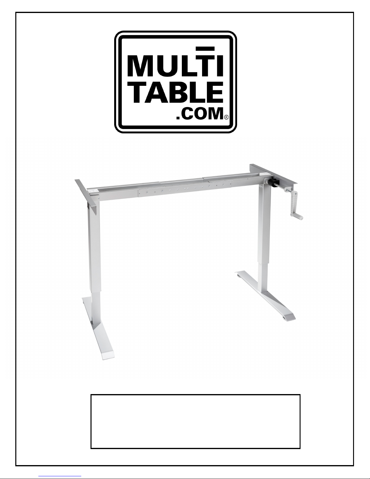
Assembly Instructions
Manual ModTable
vs 5.0
Page | ModTable | vs 4.11
Page 2

Assembly Manual Contents
1.0 GENERAL INFORMATION .......................................................................... 3
1.1 Intended Use ..................................................................................... 3
1.2 Improper Use..................................................................................... 3
1.3 Warranty ........................................................................................... 3
2.0 SAFETY INFORMATION ............................................................................. 4
2.1 Transport and Assembly .................................................................... 4
2.2 Use of the ModTable Base .................................................................. 4
2.3 Table Top Limitations ........................................................................ 4
2.4 Specific Dangers ................................................................................ 4
2.5 Maintenance and Upkeep ................................................................... 4
3.0 BOX CONTENTS ........................................................................................ 5
3.1 IMPORTANT! Read All Before Assembling .......................................... 6
3.2 Verify Package Contents .................................................................... 6
3.3 IMPORTANT! Assembly Information .................................................. 6
3.4 Assembly of the ModTable ................................................................. 6
3.4.1 Attaching the Adjustable Feet ............................................................. 6
3.4.2 Mounting the Feet ............................................................................. 7
3.4.3 Mounting the Drive Shaft .................................................................... 8
3.4.4 Mounting the Center Crossbars ........................................................... 9
3.4.4 Mounting the Center Crossbars ......................................................... 10
3.4.5 Mounting the Left Top Support .......................................................... 11
3.4.6 Mounting the HC Gear to Right Leg .................................................... 11
3.4.7 Mounting the Right Top Support ........................................................ 12
3.4.8 Assembling & Mounting the Handle .................................................... 13
3.4.9 Table Top Assembly ......................................................................... 14
3.4.10 Base Test ....................................................................................... 14
4.0 CUSTOMER SERVICE ............................................................................... 15
Page 2 | ModTable | vs 5.0
Page 3
1.0 General Information
1.1 Intended Use
Thank you for choosing MultiTable's Manual ModTable! We hope you enjoy your new purchase!
Your safety is important to us. Please follow these assembly instructions carefully and thoroughly.
Only use your ModTable indoors. Never use the base or top with any other product. The ModTable
should only be used for its intended purpose. Varying from these instructions negates your
warranty. MultiTable cannot be held liable for any injury or damage from improper use.
1.2 Improper Use
Never use the ModTable Base to lift people or loads that exceed 130 lbs (when adjusting
the Base up and down), and 250 lbs (when stationary).
The weight of the table top, along with other items that will be placed on top of the
ModTable Base must not exceed the weight capacity.
WARNING:
Do not exceed the maximum permitted load on the height adjustable
base. Overloading could lead to serious injury and damage to your
ModTable as a consequence. 60 KG = 130 lbs.
1.3 Warranty
All ModTable Bases come with a two year warranty on moving parts, and a five year
warranty on the steel.
WARNING:
Any changes or modifications to the ModTable, not expressly
approved by the manufacturer, may void the user warranty.
Exceeding the weight capacity may void the user warranty.
Page 3 | ModTable | vs 5.0
Page 4

2.0 Safety Information
2.1 Transport and Assembly
To ensure your safety and protect your ModTable it must be moved by at least two people.
Do not drag or pull the ModTable Base across the floor.
Use the tools supplied to assemble the ModTable.
2.2 Use of the ModTable Base
Do not allow children under the age of 16 to use or assemble the ModTable Base
unsupervised.
Do not use the ModTable Base on an uneven surface.
The ModTable is made for stationary use only, unless you have purchased the Wheel Kit.
2.3 Table Top Limitations
Below are the minimum and maximum table top dimensions allowed for the ModTable Base:
Without Wheel Kit:
Minimum Table Top Dimensions: W 24” x L 40”
Maximum Table Top Dimensions: W 36” x L 72”
With Wheel Kit:
Minimum Table Top Dimensions: W 24” x L 40”
Maximum Table Top Dimensions: W 30” x L 60”
2.4 Specific Dangers
When assembling your ModTable Base, ensure that you have plenty of room around the base
to avoid collisions.
2.5 Maintenance and Upkeep
Your new ModTable Base and its components are low maintenance items, but still require
regular maintenance. We recommend checking and tightening the bolts and set screws every
6 months to ensure your table raises and lowers correctly.
Should your base or other components require repairs, please contact us. Any repairs or
alterations should only completed using approved replacement parts from MultiTable.
Replacement parts are available for both in and outside of the warranty time frame.
To clean your ModTable Base and Top, use a clean damp cloth and a mild household cleaning
solution.
IMPORTANT!
Stop using the ModTable at once if you notice anything unusual.
Contact MultiTable customer service at 602.773.6911, or [email protected].
Page 4 | ModTable | vs 5.0
Page 5
3.0 Box Content
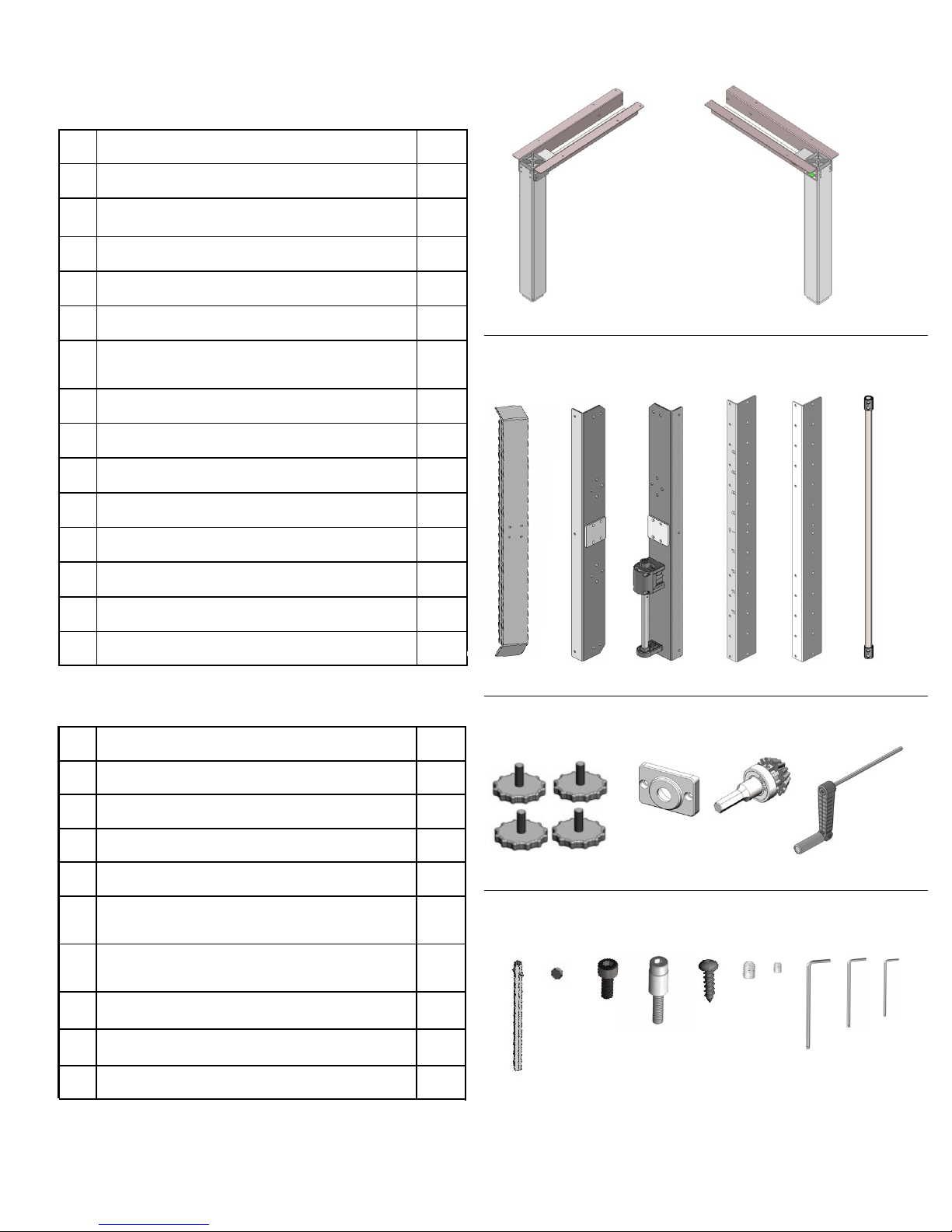
# Parts Qty
01 Left (L) leg 1
02 Right (R) leg 1
03 Foot 2
04 Left top support 1
05 Right top support—with brake box 1
06 Front Center crossbar - with
1
measurements
07 Back Center crossbar 1
08 Drive shaft 1
09 Adjustable feet 4
10 HC (handle) cover 1
11 HC (handle) gear 1
12 Handle 1
13 Long drive rod 1
01
03 04 05 06 07 08
02
14 Short drive rod 1
# Hardware Kit Content Qty
15 Small plastic dot 1
16 Bolts 18
17
Spacer bolts
18
Table top screws
Set screws (located in drive shaft,
19
part # 08)
Small set screw (located on brake
20
box, part #05)
21
Large Allen wrench 1
Medium Allen wrench 1 22
23
Small Allen wrench 1
8
10
4
1
09 10 11 12 13
14 15 16 18 19 20 21 22 23
17
Page 5 | ModTable | vs 5.0
Page 6
3.1 IMPORTANT! READ ALL BEFORE ASSEMBLING
Before assembly, read safety information in Section 2.0.
3.2 Verify Package Contents
Gently remove contents from packaging.
Check the contents for transit damage.
Ensure all parts are in the box.
In case of any damage or missing/incorrect parts, contact customer service at
602.773.6911 or at [email protected]
Do not attempt to assemble the ModTable Base if there is any damage or are any
missing/incorrect parts.
3.3 IMPORTANT! Assembly Information
Only assemble the ModTable Base with the tools supplied. (Allen wrenches)
You will need a screw driver to attach the table top to the Base.
The legs MUST be at the lowest position at all times during assembly.
3.4 Assembly of the ModTable
Important!
All bolts MUST BE FULLY TIGHTENED. After you initially tightening each bolt, you will
need to go back and double check the bolts to ensure the bolts are fully tightened.
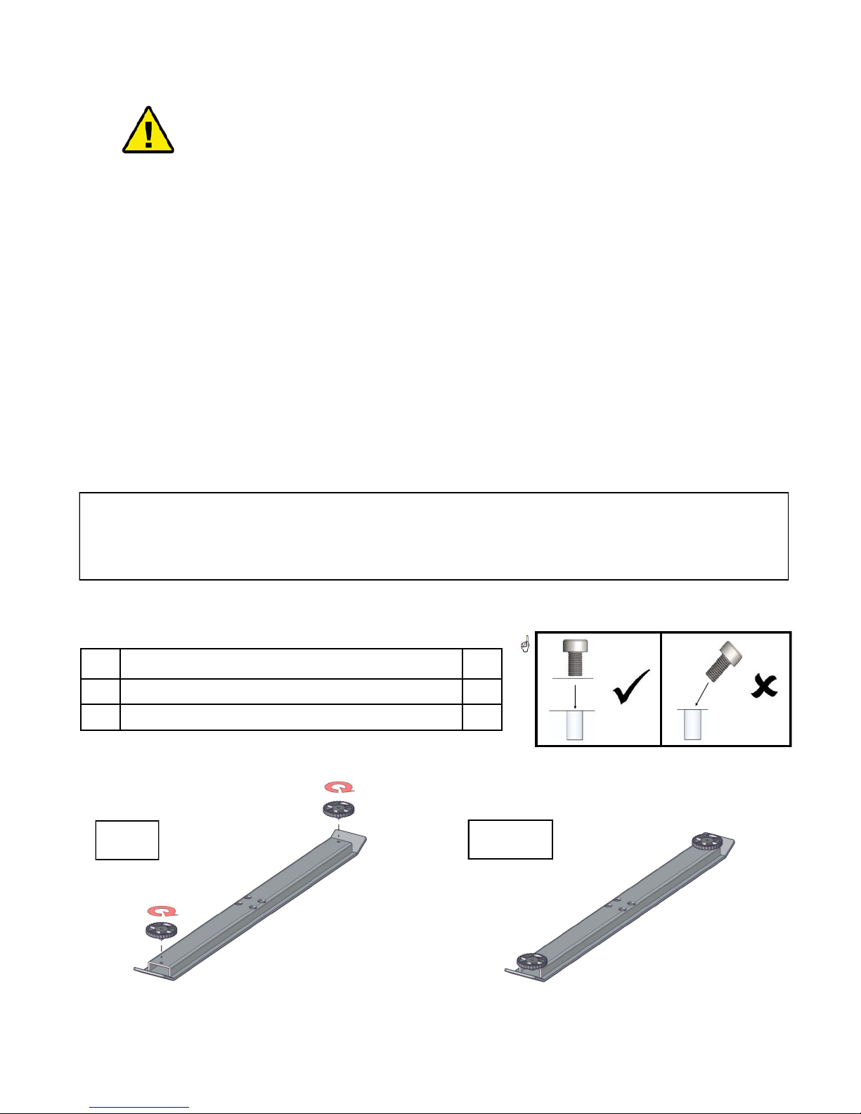
3.4.1 Attaching the Adjustable Feet
# Description Qty
03 Foot 2
09 Adjustable feet 4
1
1a
In Photo 1:
Screw adjustable
feet into foot caps.
In Photo 1a:
Foot assembly
complete.
Page 6 | ModTable | vs 5.0
Page 7
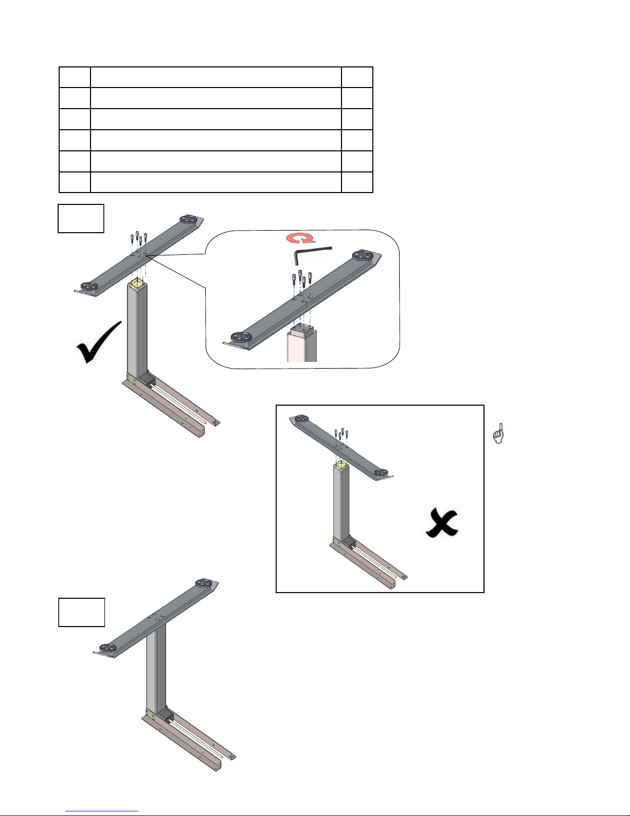
3.4.2 Mounting the Feet
# Description Qty
01 Left (L) leg 1
02 Right (R) leg—with gear shaft 1
03 Foot 2
17 Spacer Bolts 8
20 Large Allen wrench 1
2
In Photo 2:
•
Place the right foot on top of
the right (R)leg.
•
The foot should be
perpendicular to the
crossbars (see Photo 3).
Screw the bolts into the foot.
•
Repeat this process with
•
the left (L) leg and left foot.
Important!
Be sure to
attach foot in
the correct
position.
3
In Photo 3:
Finished photo of the left
and right legs.
Page 7 | ModTable | vs 5.0
Page 8
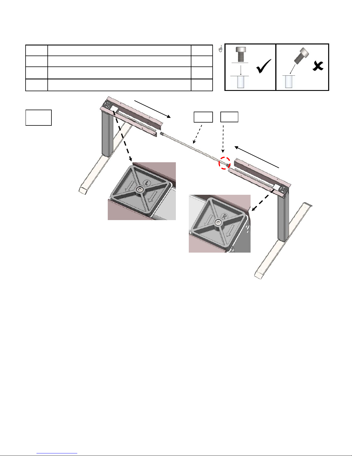
3.4.3 Mounting the Drive Shaft
# Description Qty
08 Drive shaft 1
18 Set screws 4
21 Medium Allen wrench 1
#08
#18
4
In Photo 4:
Place left (L) leg in upright position.
Slide the drive shaft over the round metal rod that extends out of the left leg. If the drive shaft
will not slide over the metal rod, slightly unscrew set screws, to allow the drive shaft to slide
over metal rod.
Take right (R) leg, slide the drive shaft over the round metal rod in the right leg.
Make sure drive shaft is centered between the metal gear connectors, and is covering the metal
rods on both sides.
DO NOT tighten set screws, yet. Proceed to section 3.4.4.
Page 8 | ModTable | vs 5.0
Page 9
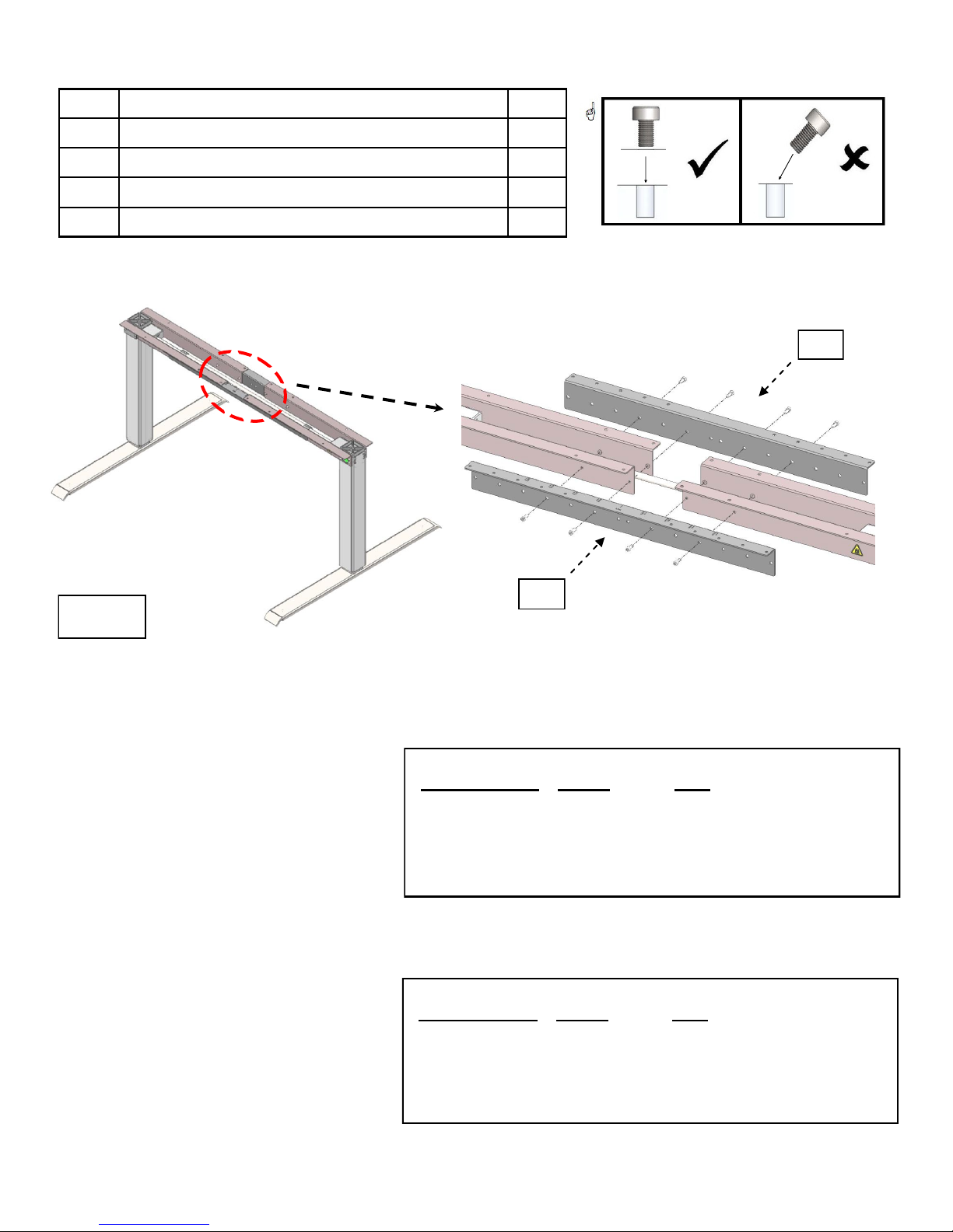
3.4.4 Mounting the Center Crossbars
# Description Qty
06 Front Center crossbar—with measurements 1
07 Back Center crossbar 1
16 Bolts 8
20 Large Allen wrench 1
#07
5
In Photo 5:
Set Base to desired width.
Attach front and back
center crossbars with
bolts.
#06
Recommended Base Width Without Wheel Kit
Crossbar Base Top
Measurement Width Size
1.0 39.5” 24”x40” (Small)
1.1 43.5” 24”x48” (Medium)
1.3 51.5” 29”x57” (Large)
1.4 55.5” 29”x72” (Extra Large)
1.0-1.4 39.5”-55.5” See section 2.3, page #4
Recommended Base Width With Wheel Kit
Crossbar Base Top
Measurement Width Size
1.0 39.5” 24”x40” (Small)
1.1 43.5” 24”x48” (Medium)
1.1 43.5” 29”x57” (Large)
N/A N/A 29”x72” (Extra Large)
1.0-1.1 39.5”-43.5” See section 2.3, page #4
Page 9 | ModTable | vs 5.0
Page 10
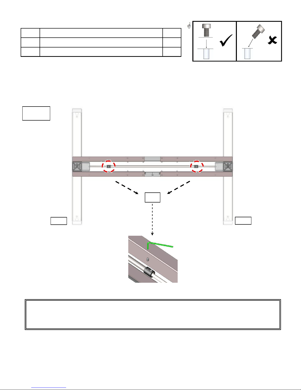
3.4.4 Mounting the Center Crossbars Continued
# Description Qty
18 Set screws 4
21 Medium Allen wrench 1
6
#18
L
Important! Photo 6:
Fully tighten the set screws in the drive shaft using the Medium Allen wrench. Tighten
set screws three times on each side to ensure screws are completely tightened. Set screws
MUST be tightened completely for the Base to function properly.
R
Page 10 | ModTable | vs 5.0
Page 11
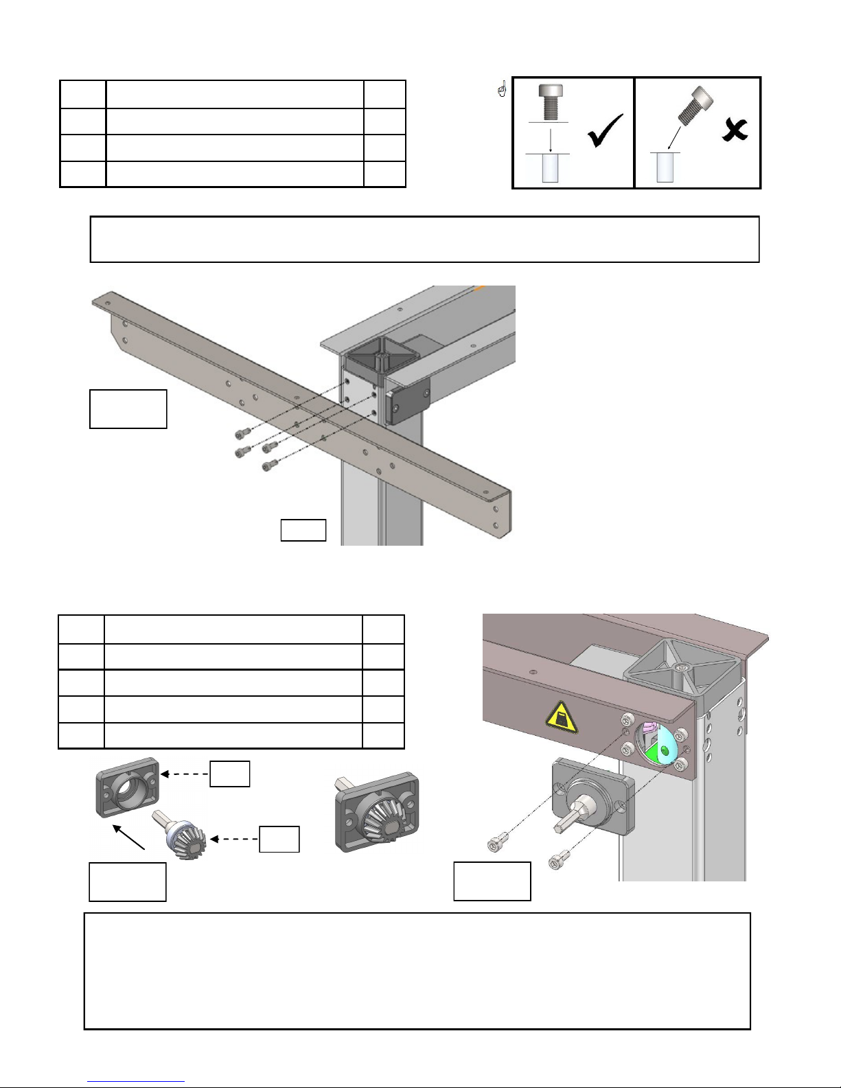
3.4.5 Mounting the Left Top Support
# Part Name Qty
04 Left top support 1
16 Bolts 4
20 Large Allen wrench 1
If you purchased a left-handed Base, the left top support will be attached to the right (R)
leg, opposite of what the picture below depicts.
In Photo 7:
Using the bolts,
7
mount left top
support to left (L)
leg.
L
3.4.6 Mounting the HC Gear to Right Leg
# Part Name Qty
10 HC (handle) cover 1
11 HC (handle) gear 1
16 Bolts 2
20 Large Allen wrench 1
#10
#11
8
IMPORTANT!
Photos 8 & 9:
Left-handed Bases - This step is completed on the Left (L) Leg.
Once the HC gear has meshed properly with the leg gears, attach the HC cover plate
with the beveled edge up. If the HC cover does not lay flat against the leg, the HC gear
has not been properly installed.
9
Page 11 | ModTable | vs 5.0
Page 12
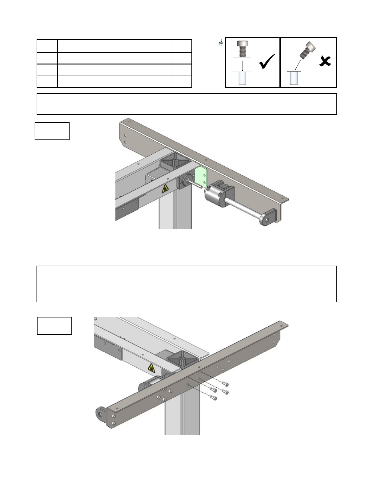
3.4.7 Mounting the Right Top Support
# Part Name Qty
05 Right top support—with brake box 1
16 Bolts 4
20 Large Allen wrench 1
If you purchased a left-handed Base, the right top support with the brake box will be
attached to the left (L) leg, opposite of what the picture below depicts.
10
In Photo 10:
Mount the right top support—with brake box to the right (R) leg.
Slide the brake box into the HC gear rod.
Important!
The brake box and HC gear rod must align in order to connect properly. If the brake
box does not line up with HC gear rod, use the handle (see photo 12) to turn the
brake box until it lines up with the HC gear rod.
11
In Photo 11:
Bolt the right top support with brake box to the right (R) leg.
Page 12 | ModTable | vs 5.0
Page 13
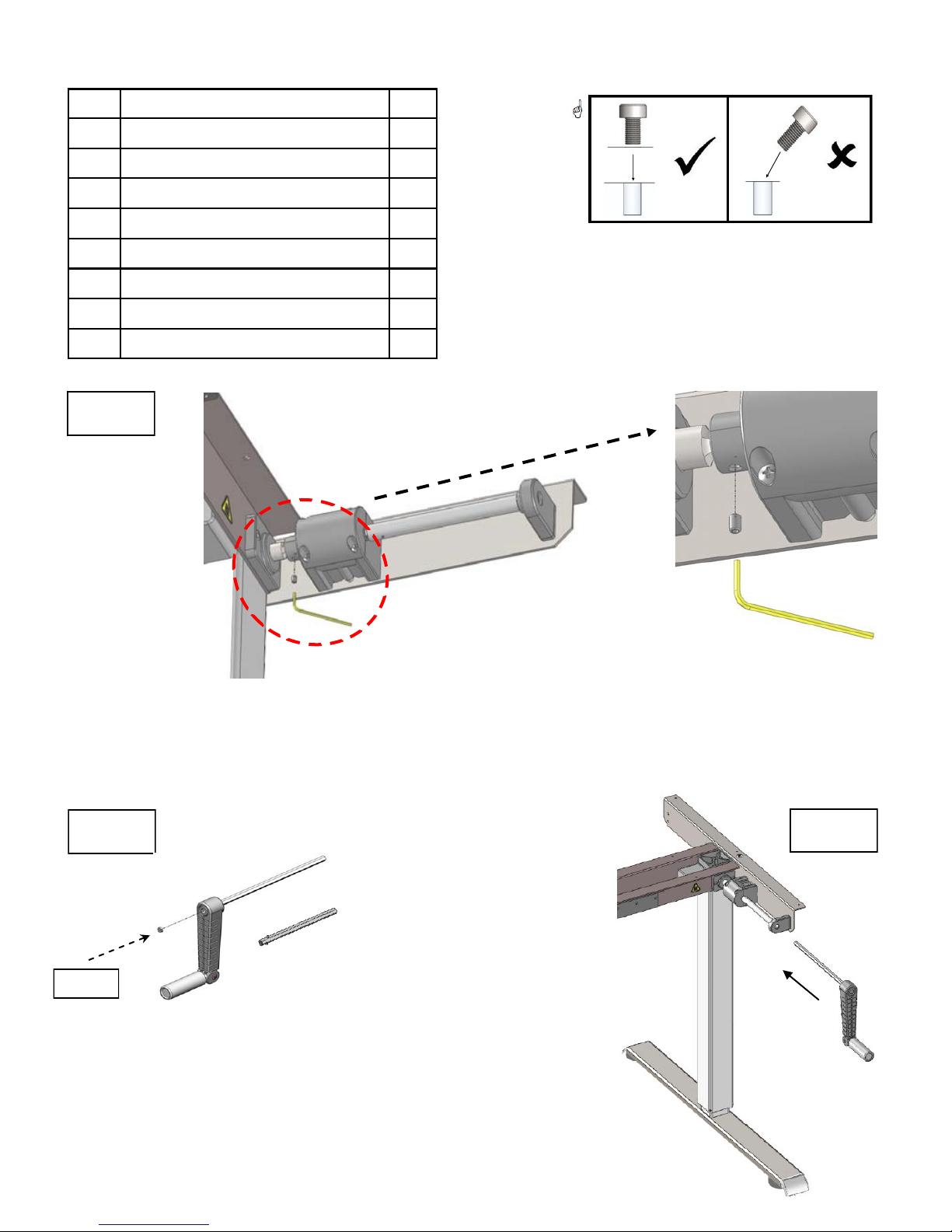
3.4.8 Assembling & Mounting the Handle
# Description Qty
12 Handle 1
13 Long drive rod 1
14 Short drive rod 1
15 Small plastic dot 1
16 Bolt (already in handle) 1
19 Small set screw 1
20 Large Allen wrench 1
22 Small Allen wrench 1
12
In Photo 12:
Tighten the small set screw into the small metal ring.
In Photo 13:
A) For Small or Medium
13
#15
Table Tops, use the
short drive rod.
B) For Large or Extra
Large Table Top, use
the long drive rod.
Cover bolt with small
plastic dot.
In Photo 14:
Slide the assembled
handle into handle
bracket.
14
Page 13 | ModTable | vs 5.0
Page 14
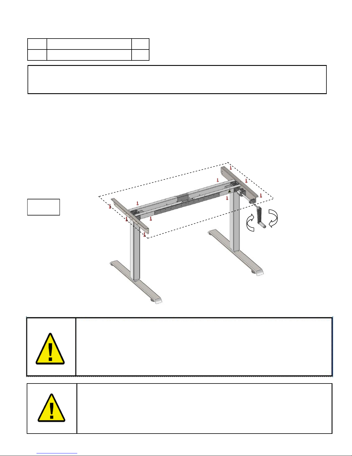
3.4.9 Table Top Assembly
# Part Name Qty
17 Table top screws 10
Important!
If you have purchased the Wheel Kit, please skip this section. Continue to the Wheel Kit
Assembly Manual now.
Slide handle out of handle bracket, and set aside.
With the assistance of another person, lay table top upside down on the a soft surface, and
carefully turn the Base over (upside down), setting it on top of the table top.
Align the holes in the Base with the holes in the table top. Attach the Base to the table top with
10 table top screws. The left top support and right top support attach to the table top
with 3 table top screws each. Use 4 table top screws to attach the center/middle of the
Base.
With the assistance of another person, carefully turn the Base and attached table top back over
to its upright position. Slide the handle back into the handle bracket.
3.4.10 Base Test
15
In Photo 15:
Turn the handle until the base reaches the highest position and then back down.
Do not continue to turn the handle past the stopping point. Doing
so will result in damage to the ModTable.
Make sure that the height adjustment can be operated undisturbed.
Keep the base away from possible obstacles, and space the ModTable at
least a half of an inch away from possible obstructions (for instance, the
wall).
Observe the provisions of Section 2 Safety Information on page 4, in
particular:
Do not leave children unsupervised with the ModTable. Children may be
unaware of the dangers presented by the table movement.
Page 14 | ModTable | vs 5.0
Page 15

4.0 Customer Service Contact Information
ModTable
By MultiTable, LLC
2255 W Desert Cove Ave Suite E
Phoenix, AZ 85029
602.773.6911
www.MultiTable.com
Page 15 | ModTable | vs 5.0
 Loading...