

Page 1
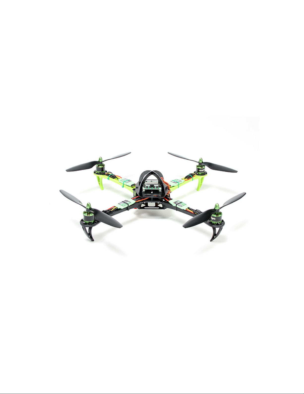
SK450
Powered by Turnigy and Multistar
Page 2

SK450
DESCRIPTION
Introducing the Turnigy SK450 quad copter powered by Multistar. Turnigy set out to make a great value,
easy to use, plug and fly quad copter without compromise. The result is a quad copter using all top tier
components and proven performance.
Turnigy started with the popular SK450 frame known for its durability, then added some detail changes
with Multistar green front arms and a crash dome for the flight controller. For the power system, Turnigy
looked to the proven Multistar line of motors and ESCs, choosing the powerful 2213 and matching them
with Multistar 20A speed controllers. When it came to the flight controller the choice was clear with the
much loved KK2.1, all pre-configured and setup in X mode. The Turnigy SK450 comes with 2 sizes of
props; 8 inch for 2200mah or smaller batteries and 10 inch for larger batteries or for those who want to add
a camera for capturing a bird’s eye view. Turnigy wraps up the package with a purpose built carrying case
with pre-cut foam inserts for the quad copter, transmitter, batteries, and all of the accessories, making
transporting and storage a breeze.
Turnigy has done all the hard work for you. Don’t spend hours trying to work out the best components to
use or time assembling. Get out there and start flying with the new, plug and fly, Turnigy SK450, powered
by Multistar.
Features:
• Special edition SK450 frame
• Multistar power system
• KK2.1 flight controller
• Includes transporting box with foam inserts
• 2 sets of props
• Pre-assembled and tuned
Specs:
• Frame: SK450
• Wheelbase or Motor to Motor Diagonal: 450mm
• Weight: 680g without battery
• Motors: Multistar 2213 935kv
• ESC: Multistar 20A
• Propellers: 0845~1045 2xCW 2xCCW
• Flight Controller: KK2.1
Included:
• 1 x SK450 plug and fly quad copter
• 4 x 0845 inch propellers 2xCW 2xCCW
• 4 x 1045 inch propellers 2xCW 2xCCW
• Velcro Straps and spare hardware
• Integrated box case with foam inserts
Page 3
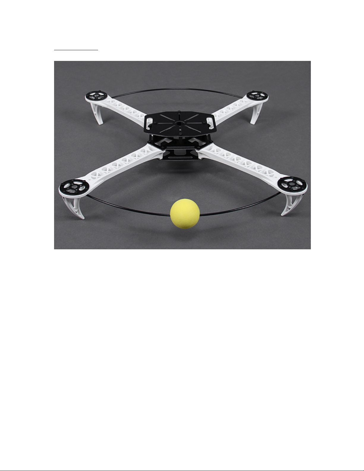
SK450 FRAME
DESCRIPTION
The Hobbyking SK450 is a brilliantly designed 450mm quad frame built from top quality materials. The
main frame is high quality glass fiber while the arms are constructed from ultra durable polyamide nylon.
This quad not only looks great, its very well thought out as well. Assembly is a breeze with pre-threaded
brass sleeves for all of the frame bolts, so no lock-nuts are required. It utilizes one size of bolt for the entire
build, making the hardware very easy to keep in order and only requiring one size of hex wrench to
assemble.
The SK450 also has an orientation feature which is quite clever. It includes a yellow foam ball which you
install on a carbon rod that mounts between the frame arms. This not only acts as a bumper to prevent
running into obstacles, it also makes for a great orientation aid to keep track of the front of the quad while
flying.
We offer a full line of multi-rotor electronics such as multi-rotor control board, ESC & motors. It has never
been easier or more affordable to get a quad in the air!
Features:
Built from top quality glass fiber and polyamide nylon.
Pre-threaded brass sleeves for all of the frame bolts.
Yellow orientation ball to keep you flying in the right direction.
Easy assembly.
Page 4
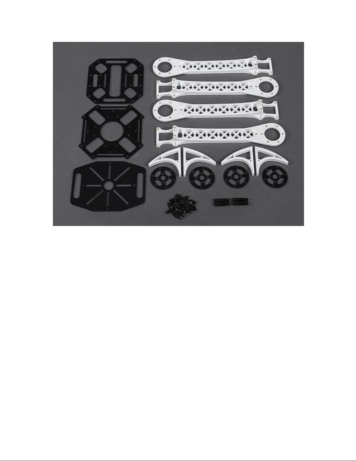
Specs:
Width: 450mm
Height: 80mm
Weight: 300g (w/out electronics)
Page 5

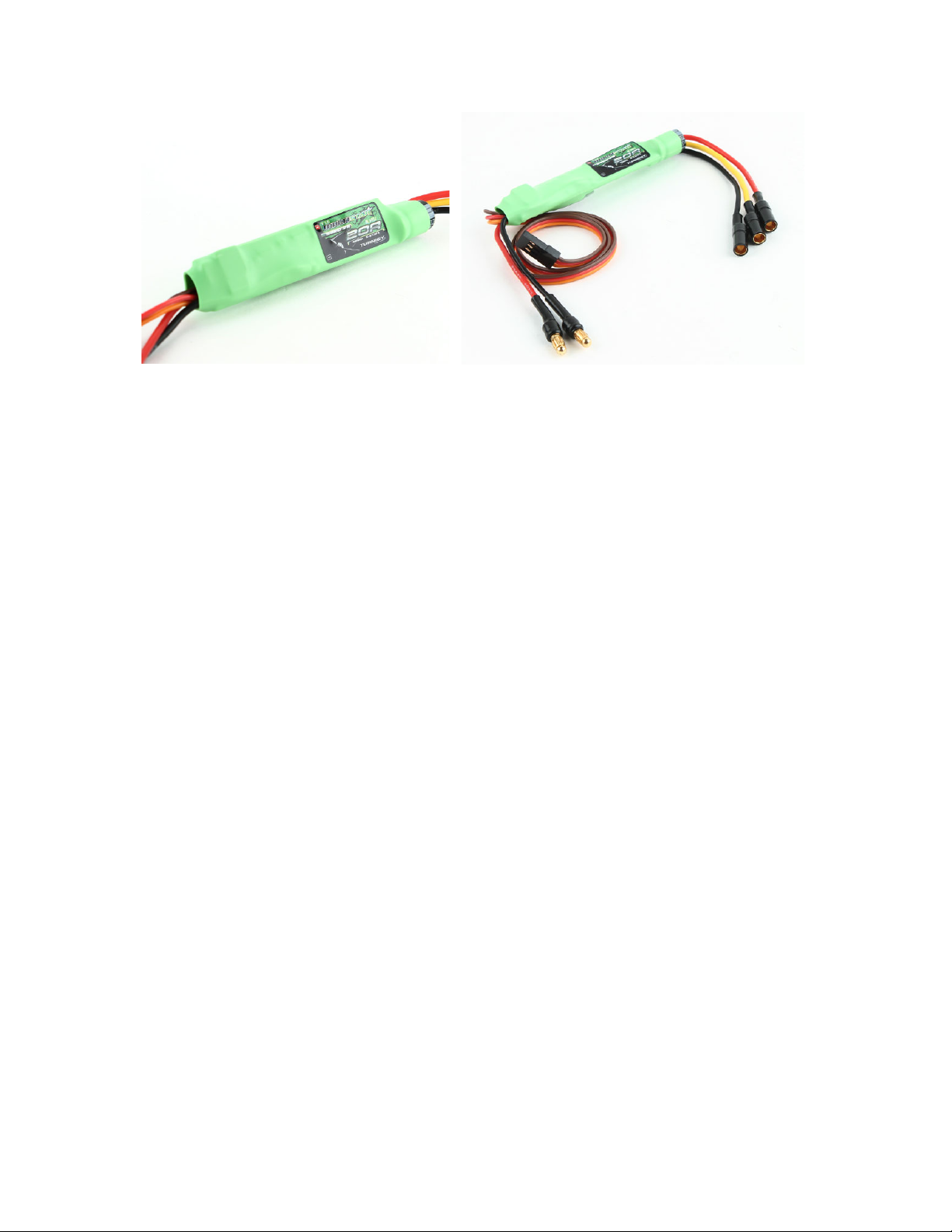
TURNIGY MULTISTAR 20A V2 SLIM ESC 2-6S
DESCRIPTION
MultiStar ESCs are a quality speed controller at a fantastic price! Designed for simple installation and easy
setup these ESCs have proven to offer excellent performance when used in Multi-rotor applications. If
you're starting out in Multi-rotors and need an easy to install solution that is tested and proven to work with
Multi-rotor craft then these speed controllers have you covered.
These V2 ESC's features BLHeli software for a very smooth yet linear throttle response, without sacrificing
a rapid, crisp, response to any throttle input.
All Multistar series ESC's come with bullet connectors installed that are suited to the ESC's rated power
handling. This allows for plug and play convenience by simply adding the appropriate battery supply
splitter (3,4 or 6 ESC) and motor lead extensions from the Multistar modular accessory line. What could be
simpler?
All Multistar ESC's feature an ATmega MCU that opens the door to customizable firmware – The V2
Multistar comes with BLheli software pre-installed, and for those so inclined a ease to use USB tool is
available for Configuration and updating via the BLHeli Suite GUI.
Please refer to the related items below for a solder free multi-rotor power solution to suit your next multirotor project.
Features:
• BLHeli Software
• USB tool updating and configuration via BLHeli GUI software
• Smooth and linear throttle control
• Slim design for easy frame installation
• Fast response to throttle input
• Atmel MCU
• Stalled motor protection
• Throttle signal lose protection
• Safe power-on (throttle lockout)
• Support 480Hz+ high refresh rates (up to 499hz)
Specs:
• Constant Current: 20A
• Input Voltage: 2-6 cell Lipoly
• BEC: Yes (linear) [Remove middle wire to disable]
• BEC Output: 5V/3A
• PWM: 8 KHz
• Max RPM: 240,000rpm for 2 Pole Brushless Motor
• PCB Size: 62mm x 13mm
• Discharge Plugs: Male 3mm Bullet Connector
• Motor Plugs: Female 3mm Bullet Connector
• Weight: 20.3g
Page 6
Page 7
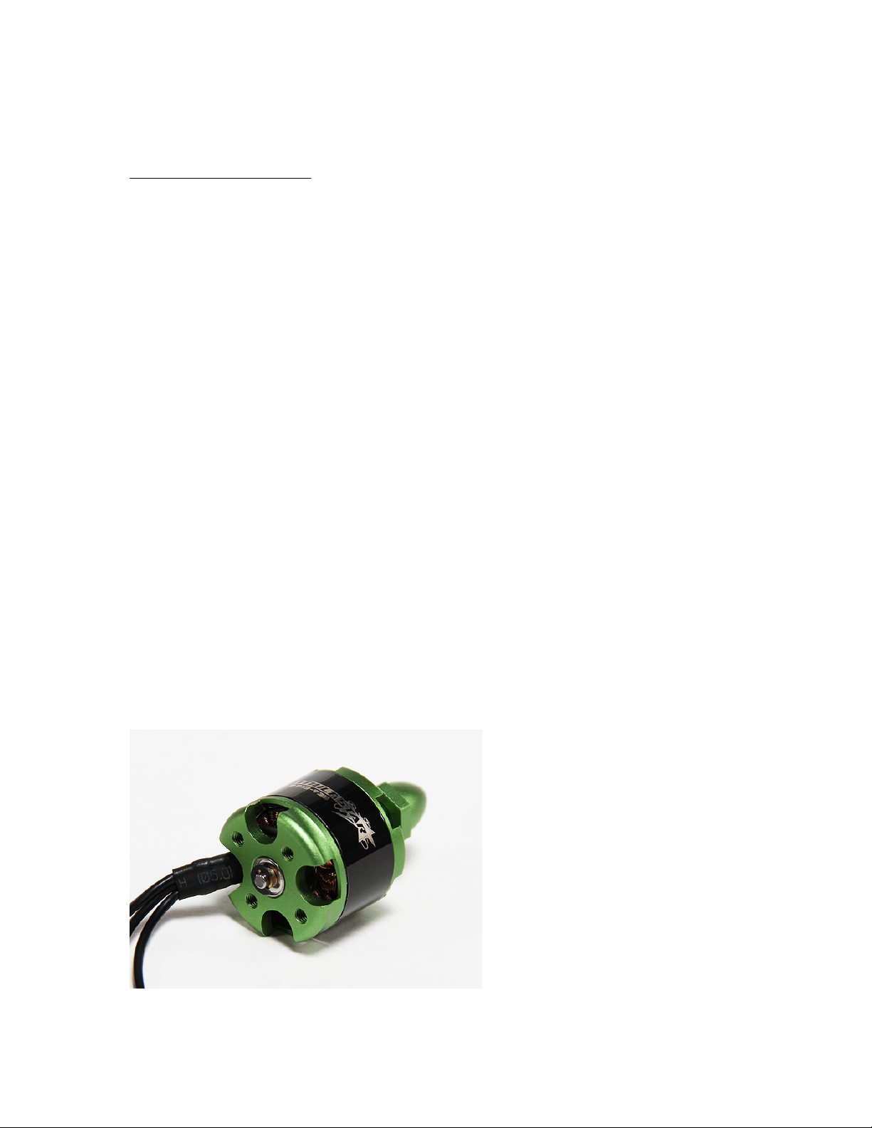
MULTISTAR 2213 935KV
DESCRIPTION
The Turnigy Multistar outrunners are designed with one thing in mind - maximizing Multi-rotor
performance! They feature high-end 45SH magnets, high quality NMB bearings, 14 Poles, custom motor
mount and all are precision balanced for smooth running, these motors are engineered specifically for
multi-rotor use.
The 2213 integrates the prop adapter into the motor housing for problem free prop attachment and
centering. Both slot (DJI style) and standard props can be utilized, so no more damaging your prop from
overnighting trying to secure your two piece prop adapters to the shaft. The 2213 has a built in aluminum
mount for quick and easy installation on your multi-rotor frame. This Multi-Star kit comes with two 1045
props one CCW and one CW and is ideal for a 3 cell set-up for a 450 size Quad, 550 Hex or 700 Octo. And
for those running a 4 cell set up can use 8045 size prop for an ultra-fast response.
These Multistar outrunners have been specifically designed from the ground up for multi-rotor use and are
not based on aeroplane motors.
Spec:
• KV(RPM/V): 935
• Lipo cells: 2-4s
• Max Surge Watts(W): 200
• Max.current(10s): 15 amps
• No Load Current: 0.4 amps
• Intemal Resistance: 0.180 ohm
• Number of Poles: 14
• Dimensions(Dia.xL): 27.9 x 25.7 mm (not counting the prop shaft)
• Motor Shaft: 3 mm (not the prop shaft)
• prop shaft: Slotted (DJI) style 8mm round (7mm flat to flat) stepped down to 6mm and a M6 prop nut
• Prop: 10 x 4.7(3 cell) 8 x 4.5 (4cell)
• Weight: 55g
• bolt hole spacing: 16mm * 19mm
Page 8
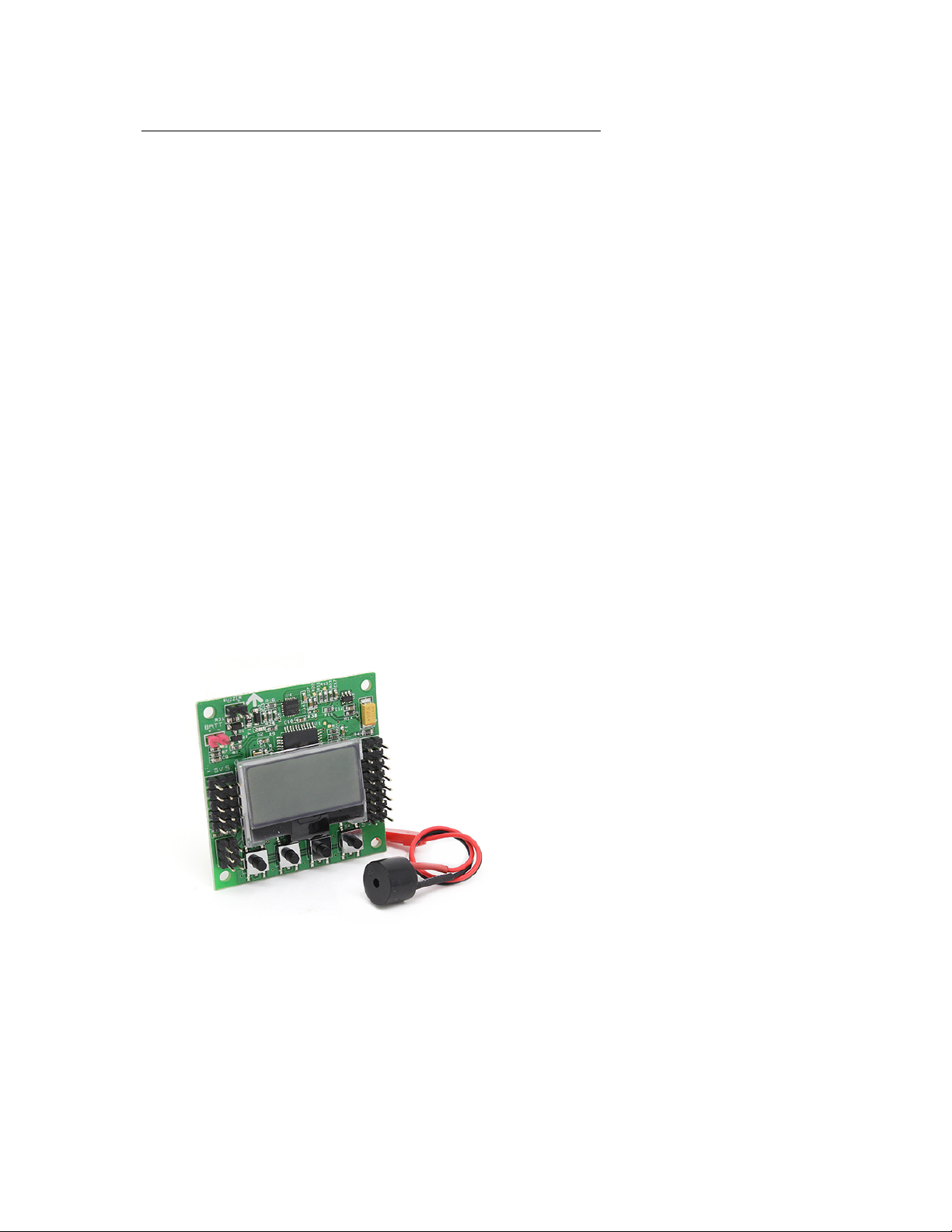
KK2.1.5 MULTI-ROTOR LCD FLIGHT CONTROL BOARD
DESCRIPTION
The next evolution of the rotor revolution is here!! The KK2.1.5 is packing new found power with updated
sensors, memory and header pins.
The KK2.1.5 is next big evolution of the first generation KK flight control boards. The KK2.1.5 was
engineered from the ground up to bring multi-rotor flight to everyone, not just the experts. The LCD screen
and built in software makes install and setup easier than ever. A host of multi-rotor craft types are preinstalled, simply select your craft type, check motor layout/propeller direction, calibrate your ESCs and
radio and you’re ready to go! All of which is done with easy to follow on screen prompts!
The original KK gyro system has been updated to an incredibly sensitive 6050 MPU system making this
the most stable KK board ever and allowing for the addition of an auto-level function. At the heart of the
KK2.1.5 is an Atmel Mega644PA 8-bit AVR RISC-based microcontroller with 64k of memory. An
additional polarity protected header has been added for voltage detection, so no need for on-board
soldering. A handy piezo buzzer is also included for audio warning when activating and deactivating the
board.
The KK2.1.5 added polarity protection to the voltage sense header and a fuse protected buzzer outputs, in
case something is accidentally plugged in incorrectly. The voltage sense line has been updated for better
accuracy. The board is clearly labeled and the voltage sense line color has been changed to red for easy
identification, making installation and connections a snap.
If you’re new to multi-rotor flight or have been unsure about how to setup a KK board then the KK2.1.5
was built for you. The 6 Pin USBasp AVR programming interface ensures future software updates will be
quick and easy.
Specs:
• Size: 50.5mm x 50.5mm x 12mm
• Weight: 21 gram (Inc Piezo buzzer)
• IC: Atmega644 PA
• Gyro/Acc: 6050MPU InvenSense Inc.
• Auto-level: Yes
• Input Voltage: 4.8-6.0V
• AVR interface: standard 6 pin.
• Signal from Receiver: 1520us (5 channels)
Page 9
• Signal to ESC: 1520us
Firmware Version: 1.6:
Pre-installed firmware.
• Dualcopter
• Tricopter
• Y6
• Quadcopter +
• Quadcopter X
• Hexcopter +
• Hexcopter X
• Octocopter +
• Octocopter X
• X8 +
• X8 X
• H8
• H6
• V8
• V6
• Aero 1S Aileron
• Aero 2S Aileron
• Flying Wing
• Singlecopter 2M 2S
• Singlecopter 1M 4S
The Mixer Editor allows you to adjust where and how much signal the motors receive from stick input and
sensors. This allows you to create any configuration possible with up to 8 motors or servos.
What is a Multi-Rotor Control board you ask?
The HobbyKing KK2.1.5 Multi-Rotor controller is a flight control board for multi-rotor aircraft
(Tricopters, Quadcopters, Hexcopters etc). Its purpose is to stabilize the aircraft during flight. To do this it
takes the signal from the 6050MPU gyro/acc (roll, pitch and yaw) then passes the signal to the
Atmega644PA IC. The Atmega644PA IC unit then processes these signals according the users selected
firmware and passes control signals to the installed Electronic Speed Controllers (ESCs). These signals
instruct the ESCs to make fine adjustments to the motors rotational speed which in turn stabilizes your
multi-rotor craft.
The HobbyKing KK2.1.5 Multi-Rotor control board also uses signals from your radio systems receiver
(Rx) and passes these signals to the Atmega644PA IC via the aileron, elevator, throttle and rudder inputs.
Once this information has been processed the IC will send varying signals to the ESCs which in turn adjust
the rotational speed of each motor to induce controlled flight (up, down, backwards, forwards, left, right,
yaw).
INITIAL SETUP
Page 10

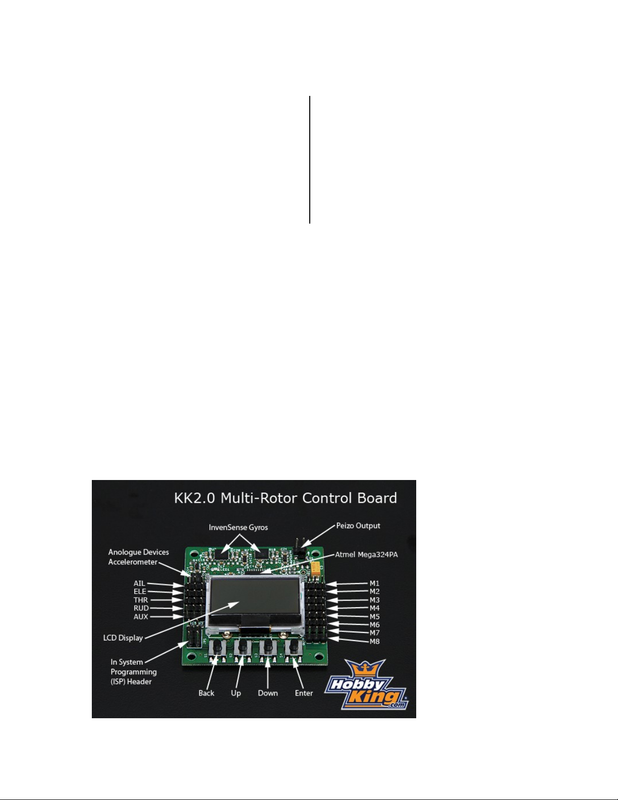
-Mount the FC on the frame with the LCD facing front and the buttons facing back.
-Connect the receiver to the pins on the left side. The negative (black or brown) lead towards the edge of
the FC. The order is, from front to back: Aileron, Elevator, Throttle, Rudder and AUX. Connect AUX to a
switched channel on your transmitter.
-Connect the motors and servos to the pins on the right side. M1 is the front one and M8 is the back one.
The negative (black or brown) lead towards the edge of the FC.
See below for how to find out which motor goes where.
DO NOT MOUNT THE PROPELLERS YET!
The M1 connector must always have a ESC connected, because this ESC will be the only one that supplies
the FC with 5V power. This ensures stable power to the FC.
The M2 to M8's 5V power pin is connected together, and any servos here will be supplied by any ESC's
connected here. There is not necessary to cut the 5V (red) lead on any ESC unless it has a Switching BEC.
With many servos, for example airplane stabilization, there may be necessary with an extra BEC. Do not
use multiple switched BEC's
-Set up a new model on your transmitter, Use a normal airplane profile.
-Turn on the power and press the menu button and enter the "Receiver Test" sub-menu.
Move each channel on your transmitter and check that the displayed direction corespondents with the stick
movements. If they disagree, reverse the channel on your transmitter.
Check that the AUX channel show "ON" when the switch on your transmitter is in your preferred on
position. If not, reverse the AUX channel on your transmitter.
-Use the trims or sub-trims and adjust the channel values shown on the LCD to zero.
-Enter the "Load Motor Layout" sub-menu and choose the configuration you want. If the configuration you
want is not listed, use the "Mixer Editor" sub-menu to make one. More on that later.
-Enter the "Show Motor Layout" sub-menu and confirm the following. Is the configuration correct? Is the
motors and servos connected the the correct output? Correct rotation direction? Does the motor speed up
when dropping the arm it is mounted on?
-Enter the "PI Editor " sub-menu and check for correct PI gain values. Use known good values or the
default ones.
-Now you can mount the propellers and test it. Arm it by give right rudder and zero throttle for a few
seconds. It will beep and the LED will turn on. Do not arm it until you have put the multicopter on the
ground and stepped away 5 meters. Safe it after landing by holding the rudder to left with zero throttle. It
will beep and the LED will turn off. Do it before you approach the multicopter. If it wants to tip over right
away, check your connections and your custom made mixer table if you have one. If it shakes and maybe
climbs after its airborne, adjust the Roll and Pitch Pgain down. if it easily tips over after its airborne, adjust
up. If it drifts away, use the trims to keep the drift down. It will normally drift away with the wind. If you
need excessive trim, check if the arms and motors have the correct angles and that the motors are good.
Increase the Roll and Pitch I gain (note the difference from P gain) until it flies straight forward without
pitching up or down.
Turn on the Self-leveling by holding right aileron while arming or disarming it. Turn it off by holding left
aileron. Alternatively you can assign this to the AUX channel. See below.
Page 11

Sub-menu descriptions.
"PI Editor":
Adjust the PI gain settings here. Use the PREV and NEXT buttons to highlight the parameter you want to
change, then press the CHANGE button. To adjust both Roll and Pitch at the same time, see the "Mode
Settings "sub-menu.
"Receiver test":
To check output from the receiver.
"Mode Settings":
-"Self Level" item: How the self-leveling function will be controlled:
--"stick": Turn on Self-leveling by holding the aileron to the right when arming or disarming. Turn it of
with left aileron.
--"AUX": AUX switch channel controls the self-leveling function.
-"I part of PI" item: How the heading-hold function will be controlled: --"On": Always on.
--"AUX": AUX switch channel controls the heading-hold function.
-"Arming" item: How the heading-hold function will be controlled:
--"Stick": Arm with right rudder and zero throttle. Disarm with left rudder and zero throttle. --"On":
Always on. Careful with this one. Use it only when the FC does not control any motors, e.g. when using it
for airplane stabilization.
-"Link Roll Pitch" item:
--"On": Edit the Roll and Pitch gain parameters together.
--"Off": Edit the Roll and Pitch gain parameters separately. Use it when the multicopter has different
inertial mass on the different axis.
"Stick Scaling":
Here you can adjust the response from the stick to your liking. Higher number gives higher response.
Similar to the endpoint or volume adjustment on your transmitter. You can also adjust your transmitter to
adjust the stick response and use the stick scaling if you want even more response.
"Misc. Settings":
-"Minimum Throttle" item: Adjust just high enough to keep all the motors running when the throttle is
above zero.
-"LCD Contrast" item: Adjust the LCD contrast.
"Self-level Settings":
-"Self-level Gain" item: The power of the self-leveling. Higher number is stronger. -"Self-level Limit"
item: Limits the max power of self leveling. Higher number is higher limit.
"Sensor Test":
Displays the output from the sensors. See if all shows "OK". Move the FC around and see that the numbers
change.
"Sensor Calibration":
Follow the instructions on the LCD. The calibration is only necessary to do once per initial setup.
"Esc Calibration":
Instructions:
1: Important: TAKE OFF THE PROPELLERS OR DISCONNECT ONE WIRE FROM THE MOTOR!!
2: Turn off the FC power.
3: Turn on the transmitter and set the throttle to max.
Page 12

4: Press down button 1 and 4, keep pressing until last step. Releasing the buttons aborts the calibration.
5: Turn on power to the FC
6: Wait for the ESC to beep its full throttle calibrated signal. Takes a few seconds, depends on the ESC. 7:
Lower the throttle to idle.
8: Wait for the idle throttle calibrated signal.
9: Release the buttons.
"Mixer Editor":
This menu lets you adjust where and how much signal the motors gets from the sticks and sensors. This
makes you able to make any configuration possible, with up to 8 motors or servos.
To change between the output channels 1-8, press CHANGE when the upper right number is highlighted.
-"Throttle" item: Amount of throttle command. Usually 100% if the output channel is connected to a ESC.
-"Aileron" item: Amount of aileron/roll command. Use positive value for motors on the right side of the
roll axis, and negative for the left side of the roll axis. The value is given by the motor's distance from the
roll axis. More is further away
-"Elevator" item: Amount of elevator/pitch command. Use positive value for motors on the front side of the
pitch axis, and negative for the back side of the pitch axis. The value is given by the motor's distance from
the pitch axis. More is further away.
-"Rudder" item: Amount of rudder/yaw command. Usually 100%. Use a positive value for a CW spinning
propeller, and negative for a CCW spinning propeller.
-"Offset" Item: Applies a constant offset to the channel. Keep this zero when it is a ESC channel, and
around 50% when connected to a servo. Fine tune servo position by adjusting this value.
-"Type:" Item: Set it to the type (servo or ESC) connected to the channel.
--For ESC: Output PWM rate is always high. Outputs zero when disarmed or throttle is at idle. Applies the
"Minimum Throttle" item from the "Misc. Settings" sub-menu when armed and throttle is above zero.
--for Servo: Output PWM rate can be high or low. Outputs the offset value when disarmed or throttle is at
idle.
-"Rate":High rate (400Hz) for ESC or digital servos, or low rate (80Hz) for analog servos.
"Show Motor Layout":
Shows the configuration graphically. Use to check your build and/or your custom mixer table.
"Load Motor Layout":
Loads one of many fixed configurations. The loaded configuration can be modified afterwards.
TUNING GUIDE:
1: Make sure the KK2 reads the transmitter stick neutrals. Go to the "Receiver Test" menu and use the trims
to get the values to zero.
2: Go to the "PI Editor" menu and set P to 150 and I to zero for both the Roll and Pitch Axis. It is only
necessary to edit the roll axis, pitch axis will be automatically changed to the same values as the roll axis.
Leave the P-limit and I-limit alone, it is seldom necessary to change them.
3: Hover the aircraft and compare the response to the multicopter in this video:
http://www.youtube.com/watch?v=YNzqTGEl2xQ ( beware of the chicken! )
4: adjust accordingly to the response.
If you are newbie and does not fly around yet, just leave the I-gain at zero or the default value. Also the
Yaw PI-gains can be left at default, but remember to zero them if you use the string tuning method.
Default PI editor settings Roll/Pitch Axis:
Pgain = 150
Plimit = 100
Igain = 50 Ilimit = 20
Yaw Axis: Pgain = 150 Plimit = 20 Igain = 50 Ilimit = 10
 Loading...