

MultiSports CC-755R User Manual

INDEX
IMPORTANT SAFETY NOTICE …………………………………………………………………… P. 1
ASSEMBLY TOOLS & HARDWARE LIST ………………………………………………………. P. 2
ASSEMBLY INSTRUCTIONS ……………………………………………………………………... P. 3 - 6
COMPUTER INSTRUCTIONS …………………………………………………………………….. P. 7 - 12
COMPLETE PARTS LIST ………………………………………………………………………….. P. 13 - 14
EXPLODED DIAGRAMS …………………………………………………………………………… P. 15 - 17
The Specifications and descriptions in this manual were accurate at the time of printing. Improvement is a
constant goal at MultiSports; therefore we reserve the right to make changes in specifications at any time
without notice and without incurring obligation.
The information in this manual is given in good faith. However any person who uses this information in any
way, does so entirely at his or her own risk. Neither MultiSports, nor its representatives can accept
responsibility for any damage or injury incurred as a result of information presented here except under the
terms of warranty of MultiSports products.

1
Congratulations on your purchase of the new MultiSports equipment. Although we go to the great lengths to
ensure the quality of our products, occasionally errors or omissions occur. Should you find a missing or defective
part in this product, please contact us within thirty days for a replacement by calling us at 713-460-8188, Emailing us
at mssales@swbell.net or visiting our web site at www.multisportsfitness.com. *Please provide the equipment
“item number” and “ part number” when requesting parts.
WARNING:
Before starting any exercise program, it is recommended that you consult your physician, especially for persons with
pre-existing health problems. Before using the new equipment, please review this manual to learn about the
features, functions, and safety operations. Should you experience any irregular physical conditions such as
dizziness, severe muscle or joint pain, pain in your chest or should any other symptoms appear: STOP
EXERCISING and consult with your physician immediately. **MultiSports assumes no responsibility for personal
injury or property damage sustained by or through the use of this product.**
SAFETY TIPS AND PRECAUTIONS:
1. Read all instructions in this manual before using this equipment. It is the owner’s responsibility to ensure that
all users of this equipment are thoroughly informed of all warnings and precautions. Use this equipment for
its intended use as described in this manual.
2. Securely tighten all nuts and bolts and inspect and tighten all parts each time you use the equipment.
**Replace any worn parts immediately and if you find that any repairs are needed, please keep the
equipment out of use until repair.
3. The safety level of the equipment can be maintained only if it is examined regularly for damage and wear.
4. The equipment should only be used on a level surface and is designed for indoor use only.
5. Warm up before you start exercising to prevent injuries
6. No more than one person should operate the equipment at one time.
7. Do not ride the equipment standing up.
8. It is recommended that you do not initiate any type of exercising within 40 minutes after a meal.
9. Keep small children and pets away from the equipment at all times
10. Appropriate clothing should be worn while exercising. Never wear loose clothing that could be caught in
moving parts. It is recommended that athletic support clothing be worn for both men and women. Athletic
shoes should always be worn while exercising. DO NOT USE with bare feet, wearing sandals, or wearing
only socks or stockings.
11. The user’s max weight to operate the equipment is 350 lbs.
12. Never use the equipment around water or while wet. Using the unit around a pool, hot tub or sauna will void
the warranty and is potentially hazardous.
IMPORTANT SAFETY INFORMATION
2
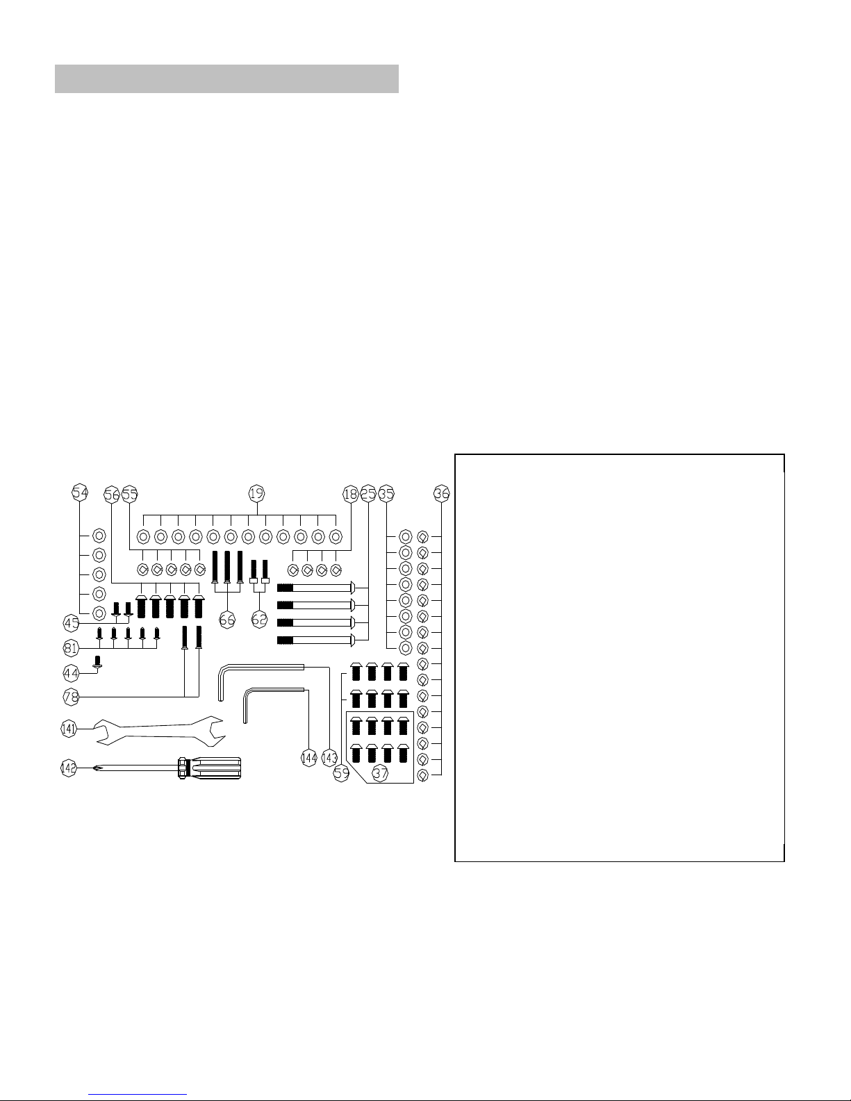
ASSEMBLY TOOLS & HARDWARE LIST
OPEN THE BOXES
Make sure to inventory all the parts that are included in the boxes. Check The Hardware Chart
for a full count of the number of parts included for proper assembly.
GATHER YOUR TOOLS
Before starting the assembly of your unit, gather the necessary tools. Having all of the equipment at hand
will save time and make the assembly quick and hassle-free.
CLEAR YOUR WORK AREA
Make sure that you have cleared away a large enough space to properly
assemble the unit. Make sure the space is free from anything that may cause
injury during assembly. After the unit is fully assembled, make sure there is a
comfortable amount of free area around the unit for unobstructed operation.
Hardware chart
18 M8 SPRING WAHER 4
19 WASHER OD16XID08X1.2MM 12
25 ALLEN SCREW M8X90MM 4
35 WASHER OD16XID08X1.2MM 8
36 M8 SPRING WASHER 16
37 ALLEN SCREW M8X15MM 8
44 SCREW M5 x 10 MM 1
45 SCREW M4 x19MM 2
54 WASHER M8 x 16MM 5
55 M8 SPRING WAHER 5
56 ALLEN SCREW M8 x 20MM (L) 5
59 ALLEN SCREW M8 x 20 MM 8
62 SCREW M5 x 20MM 2
66 SCREW M5 x 35 MM 3
78 SCREW M5 x 25 MM 2
81 SCREW M4 x 12MM 5
141 WRENCH 1
142 PHILLIPS SCREWDRIVER 1
143 M6 ALLEN WRENCH 1
144 M4 ALLEN WRENCH 1
3
ASSEMBLY INSTRUCTIONS
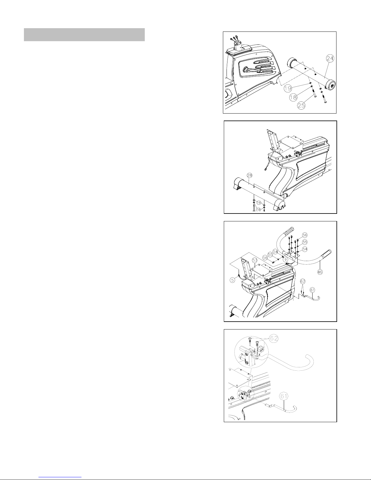
Step 1 - Attach Front Stabilizer
Attach Front Stabilizer (24) to Base Frame (1) and secure with:
2 - M16 Washers (19)
2 - M8 Spring Washers (18)
2 - M8 x 90MM Allen Screws (25)
Step 2 - Attach Rear Stabilizer
Attach Rear Stabilizer (28) to Base Frame (1) and secure with:
2 - M16 Washers (19)
2 - M8 Spring Washers (18)
2 - M8 x 90MM Allen Screws (25)
Step 3 - Install Seat Handlebar Assembly
Place Seat Handlebar (46) on top of Seat Carriage Frame (53).
Connect the Heart Rate Wire (5) to the Handlebar HR Wire (9).
Then attach Seat Handlebar (46) onto Seat Carriage Frame (53) using:
5 - M8 x 20MM Allen Screws (56)
5 - M8 Spring Washers (55)
5 - M8 Washers (54)
Attach the Seat Lock Handle (61) onto the Seat Carriage Frame (53) using:
2 - M5 x 20MM Screws (62)

4
Step 4 - Install Seat Handlebar Protecting Covers
Attach Front Protecting Cover (57) and Rear Protecting Cover (58) to Seat
Handlebar (46) using:
1 - M5 x 10 MM Screw (44)
2 - M4 x 19 MM Screws (45)
Step 5 – Install Seat and Back Support Pad Cover
Attach Seat (63) to Seat Carriage Frame (53) using:
4 - M16 Washers (19)
4 - M8 Spring Washers (36)
4 - M8 x 15MM Allen Screws (37)
Attach the Back Support Pad (64) to the Seat Carriage Frame (53) using:
4 - M16 Washers (19)
4 - M8 Spring Washers (36)
4 - M8 x 20MM Allen Screws (59)
Attach the Back Support Pad Cover (65) to the Seat Carriage Frame (53) using:
3 - M5 x 35MM Screws (66)
Step 6 - Install Right Seat Carriage Cover
Attach Right Seat Carriage Cover (77) to the Seat Carriage Frame (53) using:
2 - M5 x 25MM Screws (78)
Step 7 - Install Water Bottle Holder
Attach Upper Water Bottle Holder (79) and Lower Water Bottle Holder (80) on
the Seat Handlebar (46) using:
5 - M4 x 12MM Screws (81)
5
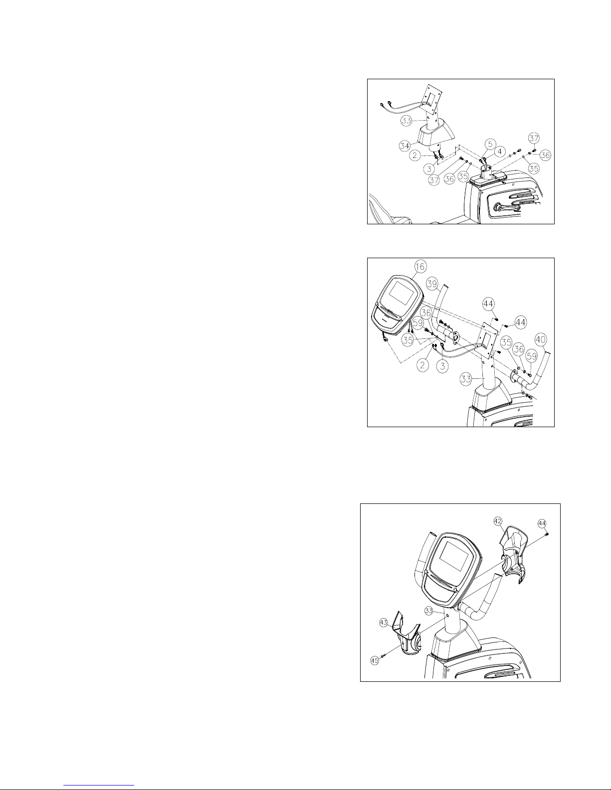
Step 8 - Install Handlebar Post Cover and Handlebar Post
Slide Handlebar Post Cover (34) up the Handlebar Post (33).
Connect the Upper Speed Sensor Wire (3) to the Middle Speed Sensor Wire (4) and
the Upper Heart Rate Wire (2) to the Heart Rate Wire (5).
Attach Handlebar Post (33) to the Main Frame (1) using:
4 - M16 Washer (35)
4 - M8 Spring Washers (36)
4 - M8 x 15MM Allen Screws (37)
Note: Be careful not to damage or pinch wires when Handlebar Post is installed.
Step 9 - Install Computer and Handlebars
Connect the Upper Speed Sensor Wire (3), the Upper Heart Rate Wire (2) to the 3
wires that are on the back of the Computer (16)
Attach the Computer (16) to the Handlebar Post (33) using:
4 - M5 x 10MM Screws (44) (On back of Computer)
Attach the Left Handlebar (39) and Right Handlebar (40) to Handlebar Post (33)
using:
4 - M16 Washer (35)
4 - M8 Spring Washers (36)
4 - M8 x 20MM Allen Screws (59)
Note: Be careful not to damage or disconnect the wires when attaching the computer.
Step 10 - Install Handlebar Post Cover
Attach the Rear Post Cover (42) and Front Post Cover (43) to the Handlebar
Post (33) using:
1 - M5 x 10MM Screw (44)
1 - M4 x 19MM Screw (45)
 Loading...