

Page 1
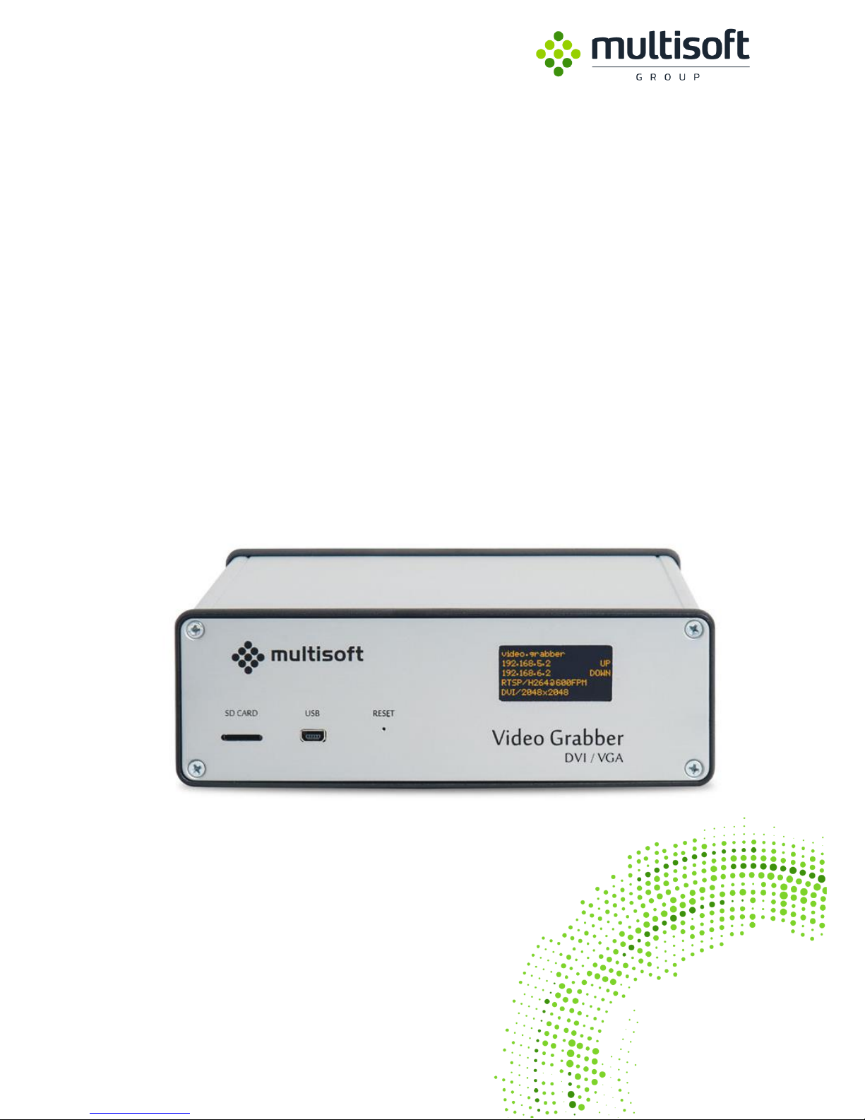
VIDEO GRABBER
Technical Manual
Page 2

Video Grabber Technical Manual - ver. 1.4
2
Version
Date
Description
Author
1.0
27.04.2015
New document
PP
1.1
28.04.2015
Revised to match software version 1.8
PP
1.2
26.10.2015
Revised to match software version 1.10
BG
1.3
20.12.2015
Revised to match software version 1.13
MM
1.4
17.03.2016
Revised to match software version 1.19
MM
Page 3

Video Grabber Technical Manual - ver. 1.4
3
Table of contents
1. Features ....................................................................................................................... 4
1.1. Technical Specification ................................................................................................. 5
2. Video adjustment ......................................................................................................... 6
2.1. Preview & adjust .......................................................................................................... 6
2.2. Extended Display Identification Data (EDID). .............................................................. 7
2.2.1. Calculating custom Modeline. .................................................................................. 9
2.2.2. Modeline string format. ......................................................................................... 11
2.2.3. Deploying custom Modeline using Video Grabber Web Interface. ....................... 14
Appendix A – Video Grabber protocol v2 ................................................................................. 15
Appendix B – Supported resolutions ........................................................................................ 17
Page 4

Video Grabber Technical Manual - ver. 1.4
4
1. Features
Multisoft Video Grabber is a device that captures video signal between Graphics Card and Monitor.
Armed with two DVI-I video sockets, for capturing Analogue (using D-SUB to DVI adaptor or hybrid
cable) as well as digital signal using Digital Virtual Interface cables. Captured video can be send via two
independent Gigabit Ethernet ports to two separated recorders. Video Capturing process is nonintrusive.*
* DDC2B compliant video signal if the Graphics Adapter providing 5V, 700 mA on pin 14 of DVI
connector
Page 5
Video Grabber Technical Manual - ver. 1.4
5
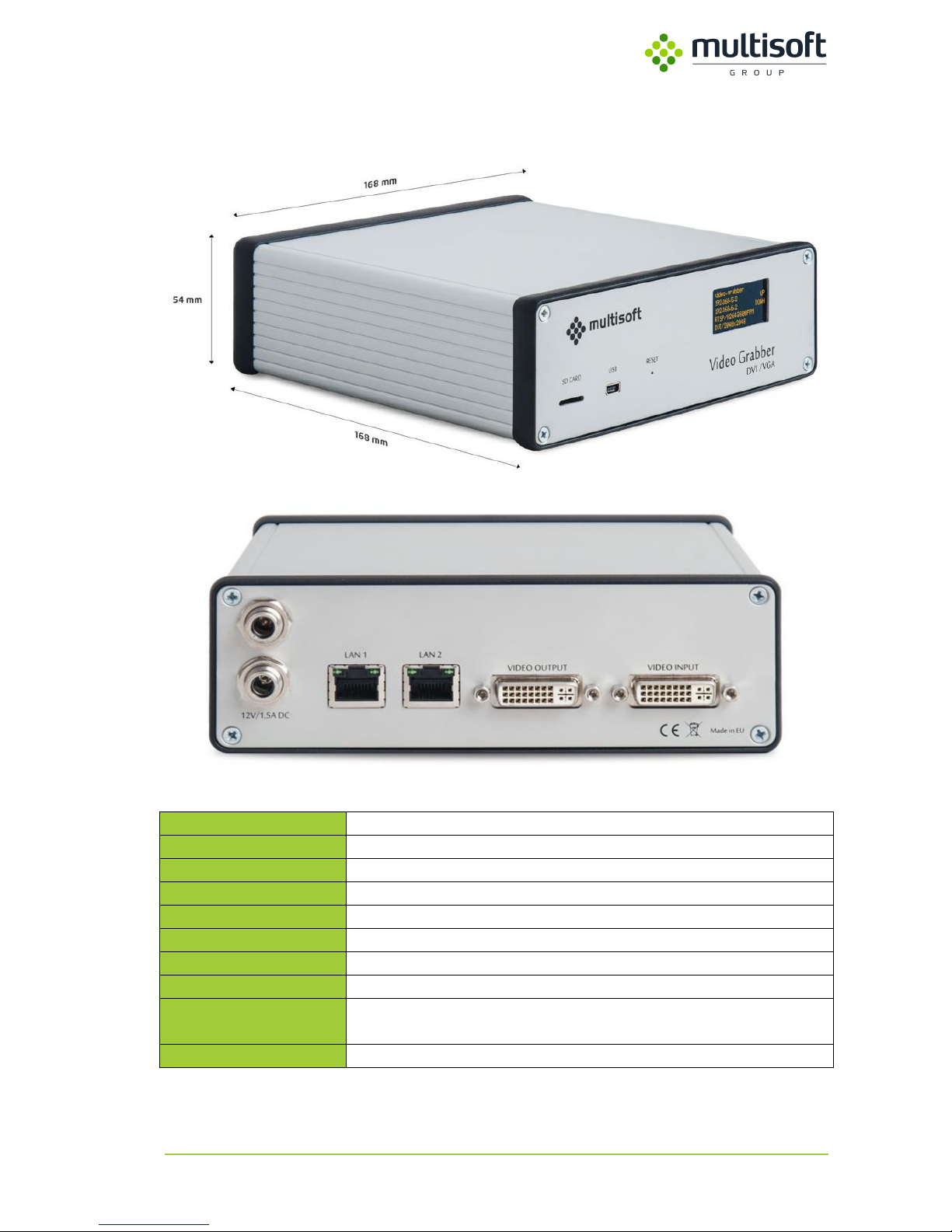
1.1. Technical Specification
Video Grabber VGA / DVI
Video resolution (VGA)
up to 1920x1200 (with pixel clock limitation up to 165 MHz)
Video resolution (SL DVI)
up to 1920x1200
Video resolution (DL DVI)
up to 2560x1600 (2048x2048) (1920x2160)
Captured video format
BMP, PNG, JPEG2000, H.264, Lossless
Operating Temperature
0 – 55 °C
Dimensions
168x168x54 [mm]
Weight
0,9 kg
Power source
DC Adapter 12V, 2A (with optional redundancy)
Video Input/output
2x DVI-I (24 + 5 pin) sockets for capturing video signal (VGA -> DVI
adaptors required for capturing analogue signal; not included)
Output
2x Gigabit Ethernet NIC’s for transferring captured video
Table 1: Technical specification
Page 6
Video Grabber Technical Manual - ver. 1.4
6
2. Video adjustment
2.1. Preview & adjust
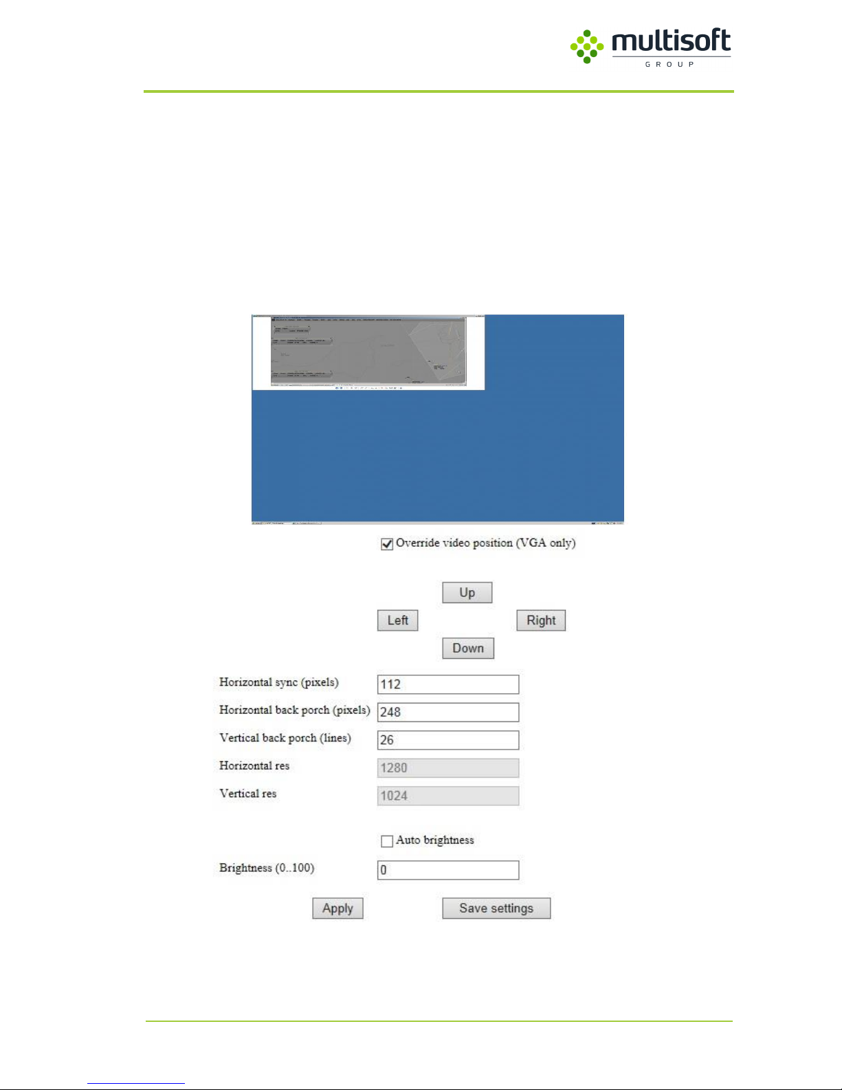
In Preview & adjust tab of Video Grabber Web Interface allowing to modify or correct detected video
setting. Because of many manufacturers and display types, detected analogue video parameters are
not always satisfactory. To do this, override video position (VGA only check button must be active).
This option activate captured video positon correction as well as change basic video Modeline settings.
All available options are shown on Figure 1. Screen adjustment.
Figure 1. Screen adjustment
Page 7
Video Grabber Technical Manual - ver. 1.4
7
2.2. Extended Display Identification Data (EDID).
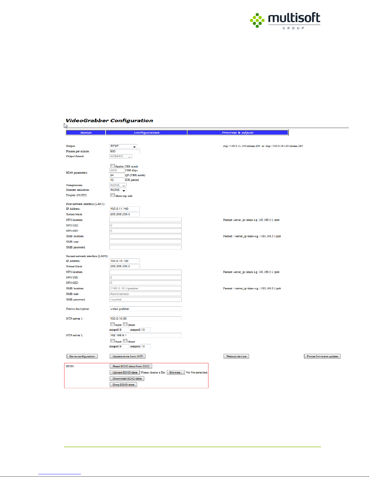
Video Grabber is designed to work with many different types and models of analog display devices.
In order to receive correct parameters of display device or monitor, we use information that
can be obtained directly from a connected device. For this purpose, we will use the EDID
section in the Configuration tab.
Figure 2. Video Grabber Configuration – EDID section
Page 8
Video Grabber Technical Manual - ver. 1.4
8
Item
Description
Read EDID data from DDC
Reading all supported Modelines reported by connected device and use this
data as new EDID table.
Upload EDID data
Allow to upload previously saved EDID data from disk.
Download EDID data
Allow to save EDID table to disk.
Drop EDID data
Clear EDID table in device and load default EDID table.
Table 2. Video Grabber EDID sections parameter description
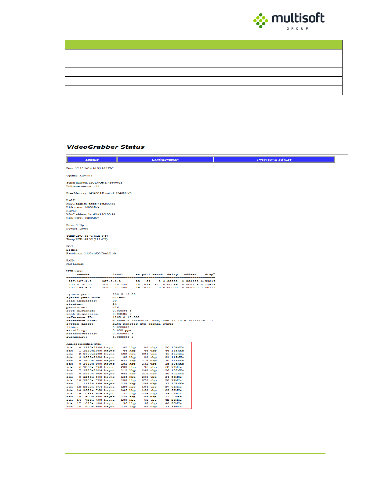
In order to check currently used EDID table please use Status tab in web-based Video Grabber
interface as is shown on Figure 3. Video Grabber Status Tab – EDID table.
Figure 3. Video Grabber Status Tab – EDID table
Page 9
Video Grabber Technical Manual - ver. 1.4
9
2.2.1. Calculating custom Modeline.
In some hardware configurations, you need to calculate custom Modeline because of the screen
resolution, which has not been sent from the display to Video Grabber via EDID (Extended Display
Identification Data) or because Pixel Clock of this resolution is higher than supported by device. Some
Graphics Adapters are provided tools to set or check actual Modeline but not all graphics drivers
display this information. In this case, you will need additional software to calculate custom one which
will be properly recognized by device. The 3rdparty tool, called Custom Resolution Utility (CRU) will be
useful. You can download it from http://www.monitortests.com/cru-1.2.6.zip.
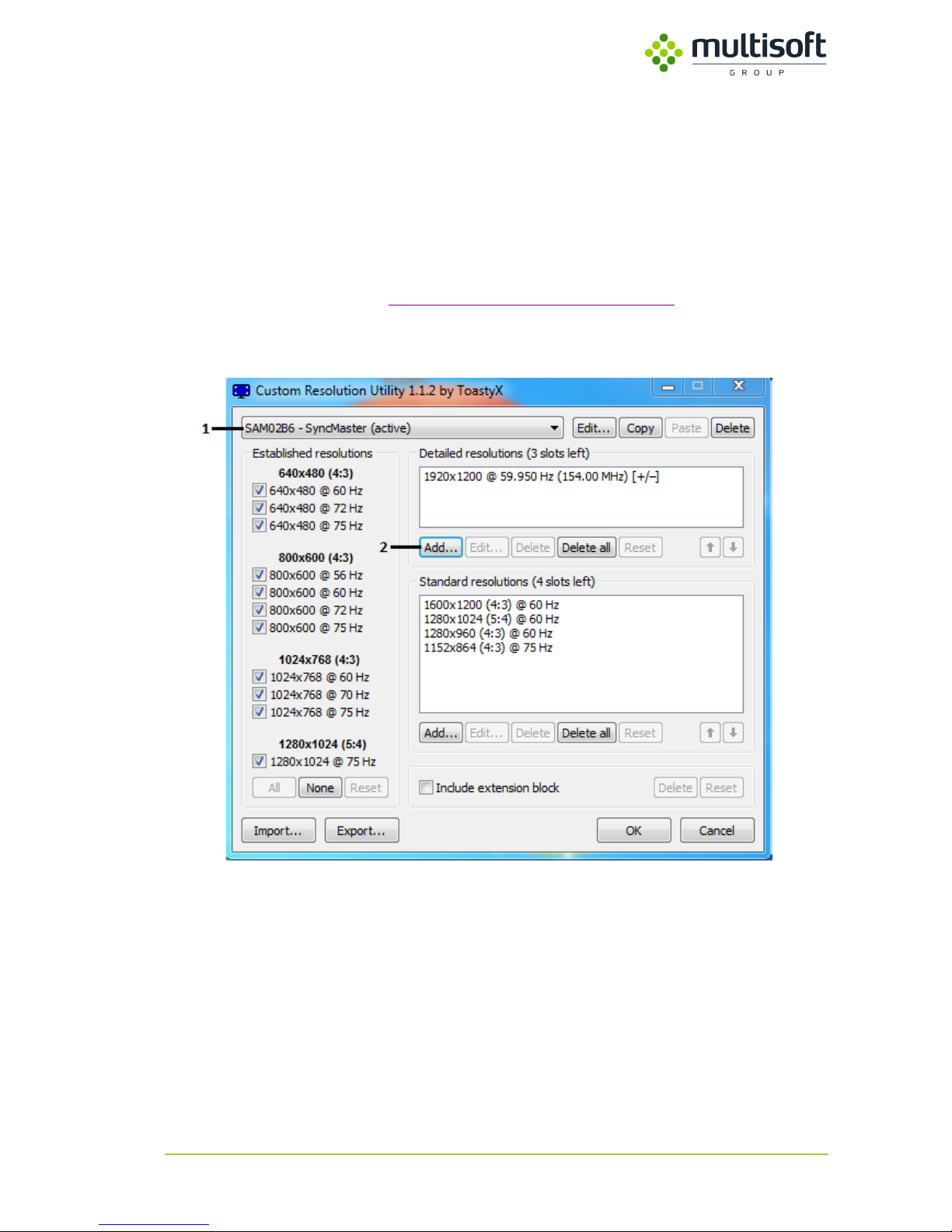
No installation is necessary. Simply run CRU.exe and main program window will be displayed as is
shown on the Figure 4. CRU – main window.
Figure 4. CRU – main window
1. From Drop Box (1), please select monitor which one is used for display custom resolution.
This utility take information about connected monitors directly from Windows registry, so
this list should be up-to-date. This option is useful only when we calculate Modeline on the
system which will be recorded. If another computer is used to calculate Modeline just leave
this option on default value.
2. Because expected resolution is not displayed in any place click Add... button (2) for add it.
After clicking on the add button, new window appears, where you can set and read
parameters necessary to calculate new Modeline for the required resolution.
Page 10
Video Grabber Technical Manual - ver. 1.4
10
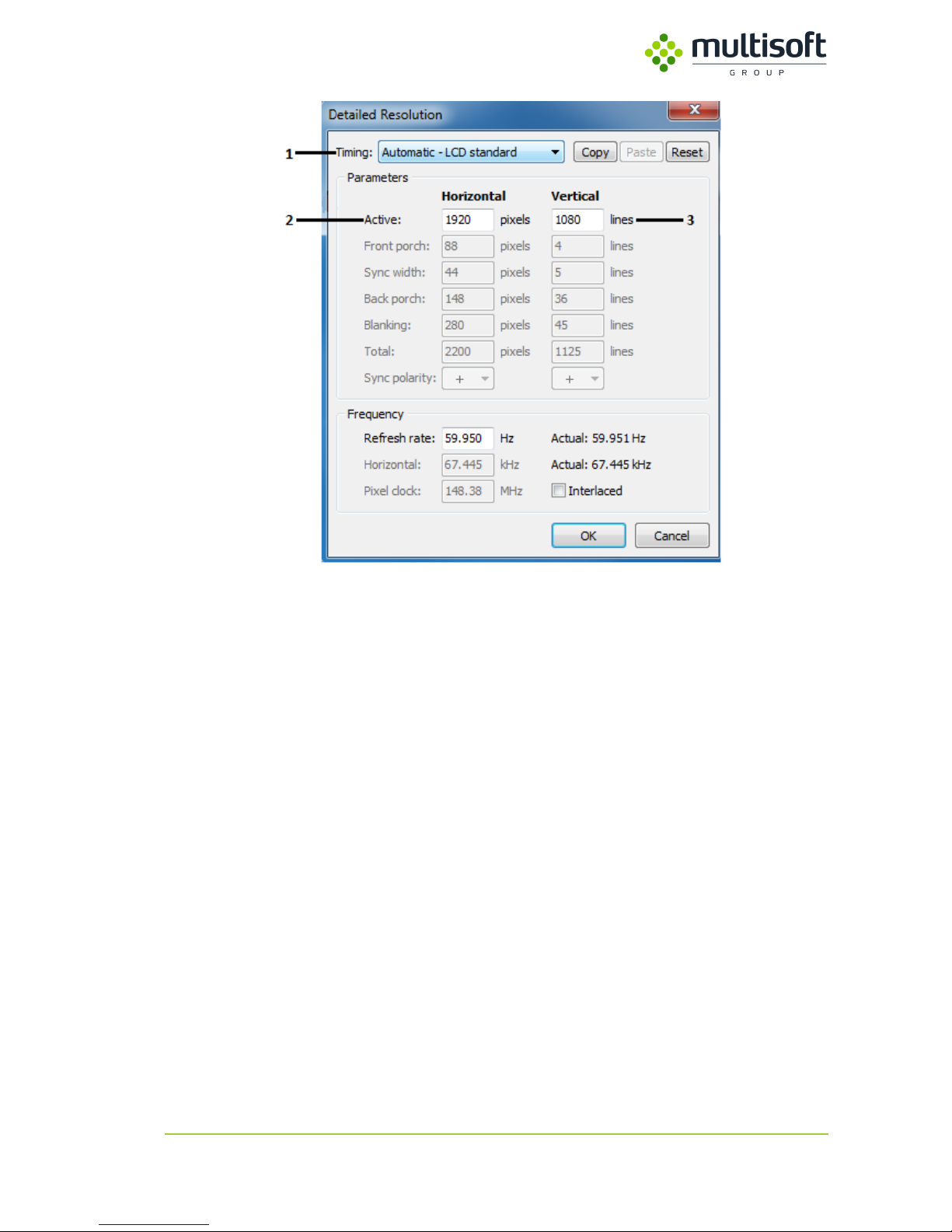
Figure 5. New custom resolution add window.
3. From timing Drop-Box button please select Automatic – LCD standard (1).
4. In the two fields below please type horizontal number of pixels (2) and vertical number of
lines (3). All remaining fields will be filled automatically.
Page 11
Video Grabber Technical Manual - ver. 1.4
11
2.2.2. Modeline string format.
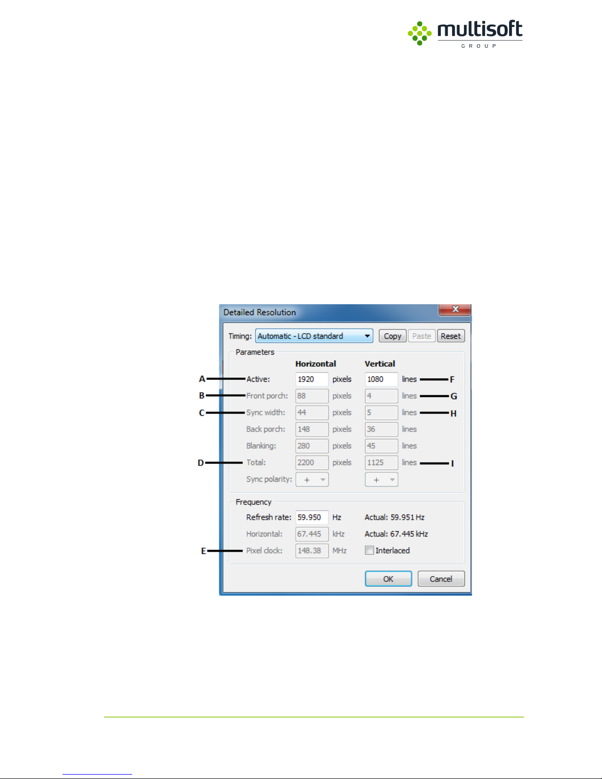
In order to understanding Modeline structure, please refer to Figure 6. Example of Modeline
string for resolution 1920x1080. Every single parameter of this string is necessary for device
to properly capture analogue signal. Each of them including referred field in Modeline
calculator is described later in this section. Let’s take a look how this string is build. Please
refer to Figure 6. Example of Modeline string for resolution 1920x1080.
1
2
3 4 5 6 7 8 9
10
11
12
13
Modeline
"1920x1080"
148
1920
2008
2052
2200
1080
1084
1089
1125
-hsync
+vsync
Figure 6. Example of Modeline string for resolution 1920x1080.
Figure 7. Modeline calculation
Page 12
Video Grabber Technical Manual - ver. 1.4
12
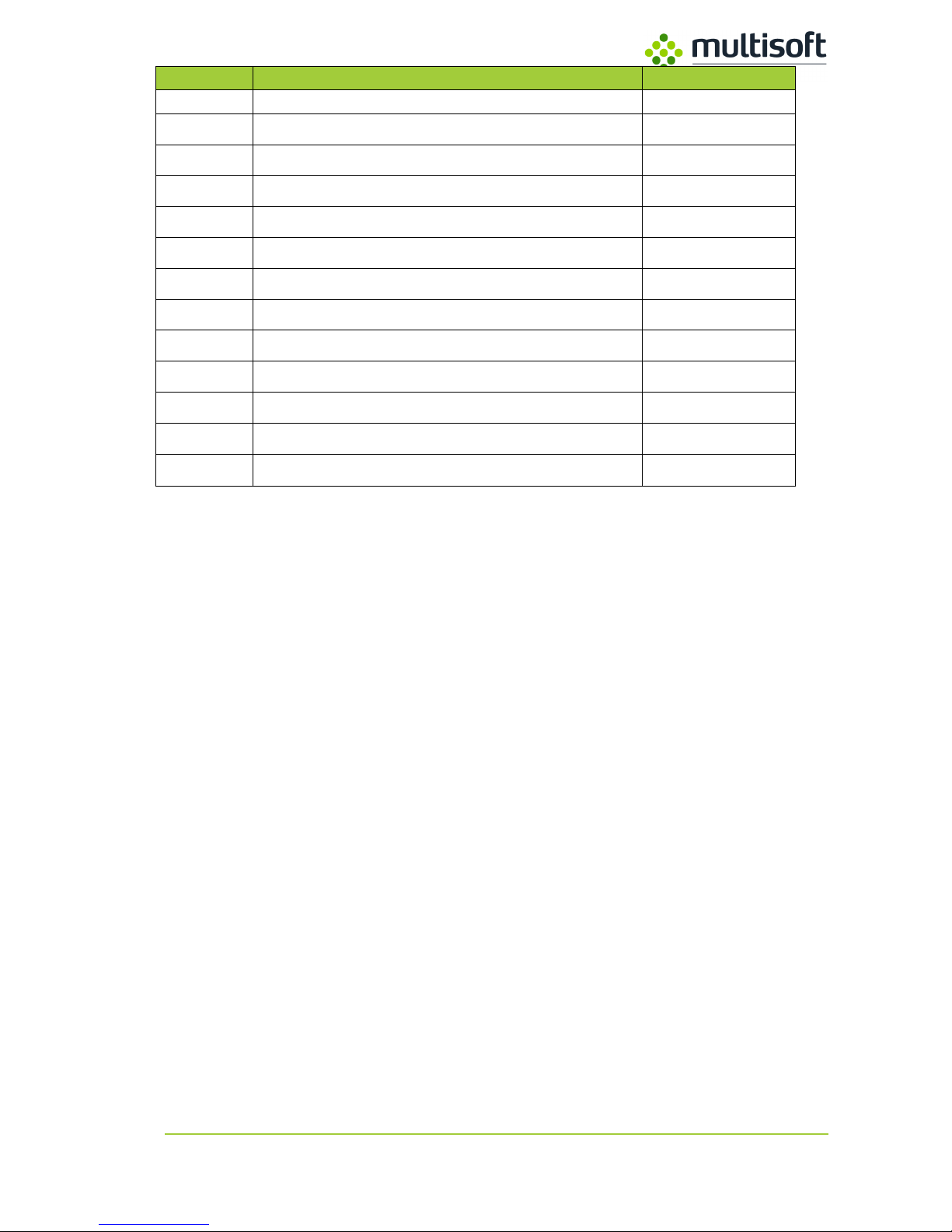
Table 3. Modeline parameters description table (ref. to Figure 7 for values).
Parameter
Description
Value
1
Constant value: Modeline
Modeline
2
Modeline text description
Text
3
Pixel clock
E
4
Expected horizontal pixels
A 5 Expected horizontal pixels + front porch
A + B
6
Expected horizontal pixels + front porch + sync width
A + B + C
7
Total horizontal pixels
D 8 Expected vertical lines
F
9
Expected vertical lines + front porch
F + G
10
Expected vertical lines + front porch + sync width
F + G + H
11
Total vertical lines
I
12
Horizontal sync polarity
+hsync / -hsync
13
Vertical sync polarity
+vsync / -vsync
Page 13

Video Grabber Technical Manual - ver. 1.4
13
First parameter (1) is constant value and should be typed directly as Modeline.
Second parameter (2) is text value for easiest Modeline identification. This parameter must be
between quotes. In this example we define resolution 1920x1080 then, for recognize this Modeline,
text string is “1920x1080”.
Next parameter (3), is Pixel Clock. As we can see on screen it is 148.38 (E). Because this value should
be integer, then type 148.
Fourth one (4) is expected horizontal resolution in pixels. Because in this example we want to set
1920x1080, then we type 1920 as (A).
Next one (5) is sum of expected horizontal resolution and front porch (A+B),
so (1920 + 88 = 2008).
Sixth parameter (6) is sum of expected horizontal resolution (A), front porch (B) and sync width (C)
then (1920 + 88 + 44 = 2052).
Next parameter (7) is horizontal pixel total. In this example it is 2200(D).
Parameters from 8 to 11 are responsible for vertical settings.
Parameter (8) is the required number of vertical lines (F), in this case - 1080.
Next (9) is the sum of the required vertical lines (F) and front porch (G), then (1080 + 4 = 1084).
Another one (10) is sum of required vertical lines (F), front porch (G) and sync width (H) then result is:
(1080 + 4 + 5 = 1089).
The last one numeric parameter (11) is total number of vertical lines (I) in this example, 1125.
Last two parameters in Modeline, string are horizontal (12) and vertical (13) sync polarity. This
parameters are used the remaining signal polarity combination to detect high resolution modes in the
same horizontal pixels value on multiscan monitors. Only four combinations are possible:
( [ +hsync / +vsync ], [ +hsync / -vsync ], [ -hsync / +vsync ], [ -hsync / -vsync ] ).
All parameters in Modeline string are space separated, different separation symbol is not
acceptable and take no effect with device.
Page 14
Video Grabber Technical Manual - ver. 1.4
14
2.2.3. Deploying custom Modeline using Video Grabber Web
Interface.
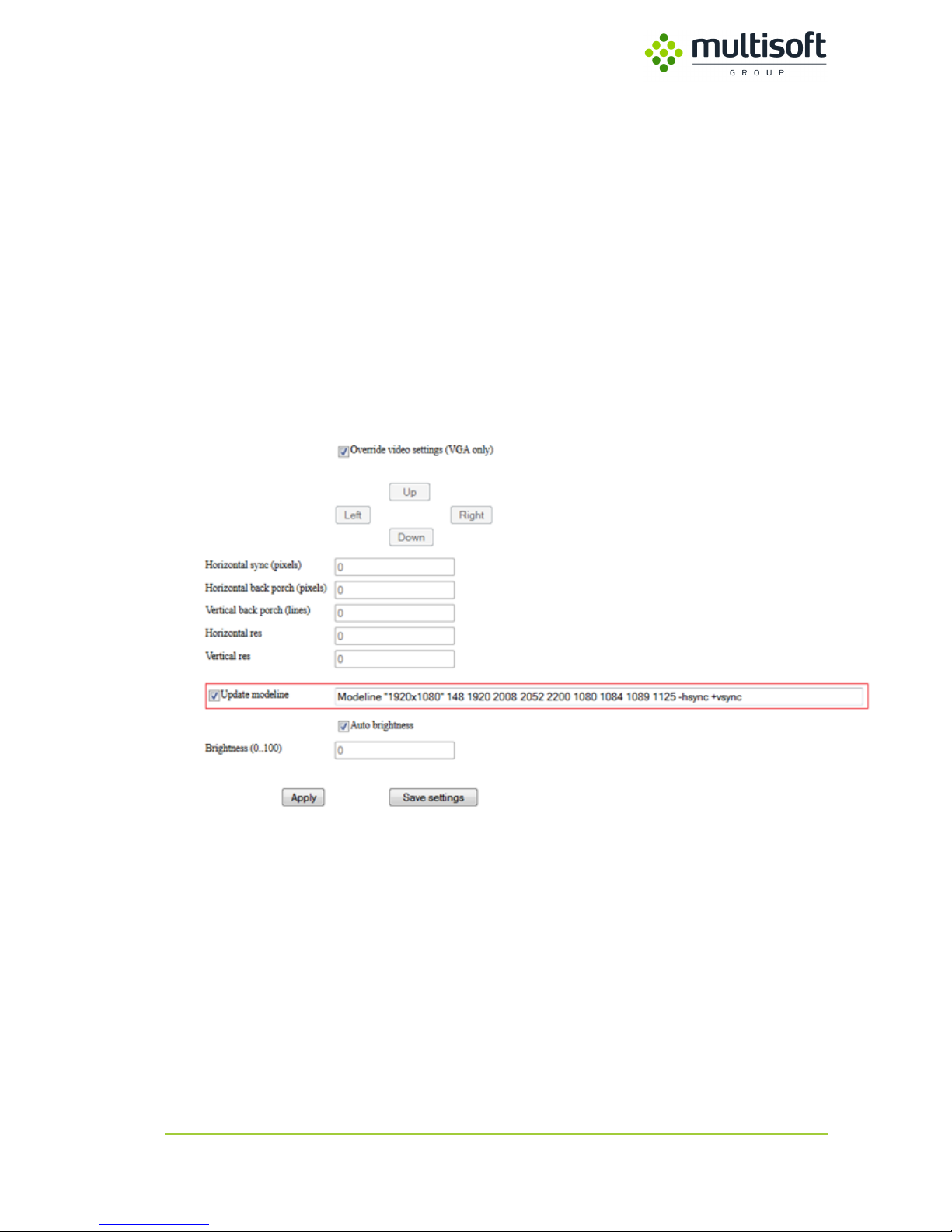
In Preview & Adjust tab is a special field, where we can define our custom modeline. To do that Override
video position (VGA only) and Update modeline checkboxes, must be checked.
In highlighted text field (see fig. 15), please enter newly calculated modeline in correct syntax and click
Apply button to check it. If this new modeline is calculated correctly, captured screen should be appear
in preview window and detected signal type and resolution, should be visible on device status LCD
display. Finally press Save settings button, to save this modeline into device EDID table.
Notice: Any changes made to previously defined Modeline, will REPLACE this Modeline in device EDID
table. Please make backup of you current EDID table before use this utility and use it carefully, because
wrong defined Modeline will result no video capture from connected device.
Page 15

Video Grabber Technical Manual - ver. 1.4
15
Appendix A – Video Grabber protocol v2
Data is streamed using UDP packets. Every frame is identified by header that is formatted:
MAGIC: 4 * UCHAR header: ‘V’ ‘G’ ‘B’ ‘R’
VER: UCHAR version: 0x01
VID_TYP: UCHAR frame type:
Bits 2:0 – video frame format:
0x0 – Microsoft BMP,
0x1 – PNG,
0x2 – JPEG2000,
0x3 – JPEG,
0x4 – RAW,
0x5 – H264/ES,
0x6 – LOSSLESS
Bit 3 – compression settings:
0x0 – no compression,
0x1 – ZIP compression
Bit 4 – CRC settings for video data:
0x0 – CRC disabled on VID_DATA, VID_CRC field has no correct data,
0x1 – CRC enabled on VID_DATA, VID_CRC field has correct data
Bits 7:5 – unused, reserved for future use
VID_NUM: USHORT next frame number,
VID_LEN: UINT length of the frame,
VID_SEC: UINT frame timestamp (seconds), time 0 ≥ 1970-01-01 00:00:00 +0000 (UTC),
VID_USEC: UINT frame timestamp (microseconds), time 0 ≥ 1970-01-01 00:00:00 +0000 (UTC),
VID_CRC: USHORT Video frame CRC, includes VID_LEN bytes of VID_DATA field: crc16-ccitt,
HDR_CRC: USHORT header CRC, includes bytes from MAGIC to VID_CRC: crc16-ccitt,
VID_DATA: VID_LEN * UCHAR data from video frame.
Page 16

Video Grabber Technical Manual - ver. 1.4
16
Types of data:
UCHAR – one byte field,
USHORT – two byte field written according to network notation,
UINT – four byte field written according to network notation,
Pseudo C description, assuming that:
Unsigned char = 8 bitts,
Unsigned short = 16 bitts,
Unsigned int = 32 bitts,
Structure is packed
typedef struct {
unsigned char[4] MAGIC;
unsigned char VER;
unsigned char VID_TYP;
unsigned short VID_NUM;
unsigned int VID_LEN;
unsigned short VID_CRC;
unsigned int VID_SEC;
unsigned int VID_USEC;
unsigned short HDR_CRC;
unsigned char[VID_LEN] VID_DATA;
}
VideoGrabber_PseudoFrame_t;
After connecting to device, bytes ‘V’ ‘G’ ‘B’ ‘R’ must be found. After that if CRC from header and CRC
in the structure are the same, the beginning of sequence has been found. If they are different then we
can assume that synchronization bytes occurred as an element of video frame, so next header has to
be found. After finding right header, next one doesn’t have to be found, because it can be calculated:
Next_fram_off = current_frame_off + sizeof (VideoGrabber_PseudoFrame_t).
In case of losing some data (network problems) synchronization process has to be repeated.
Page 17
Video Grabber Technical Manual - ver. 1.4
17
Appendix B – Supported resolutions
Horizontal(pixel)
Vertical(lines)
Refresh Rate(Hz)
VGA
DVI
640
480
60
720
400
70
800
600
60
832
624
75
1024
768
60
1152
864
60
1152
864
75
1280
600
60
1280
720
60
1280
800
60
1280
960
60
1280
1024
60
1360
768
60
1400
1050
60
1440
900
60
1600
900
60
1600
1200
60
1680
1050
60
1920
1080
60
1920
1200
60
1920
1440
60
2048
1536
60
2048
2048
60
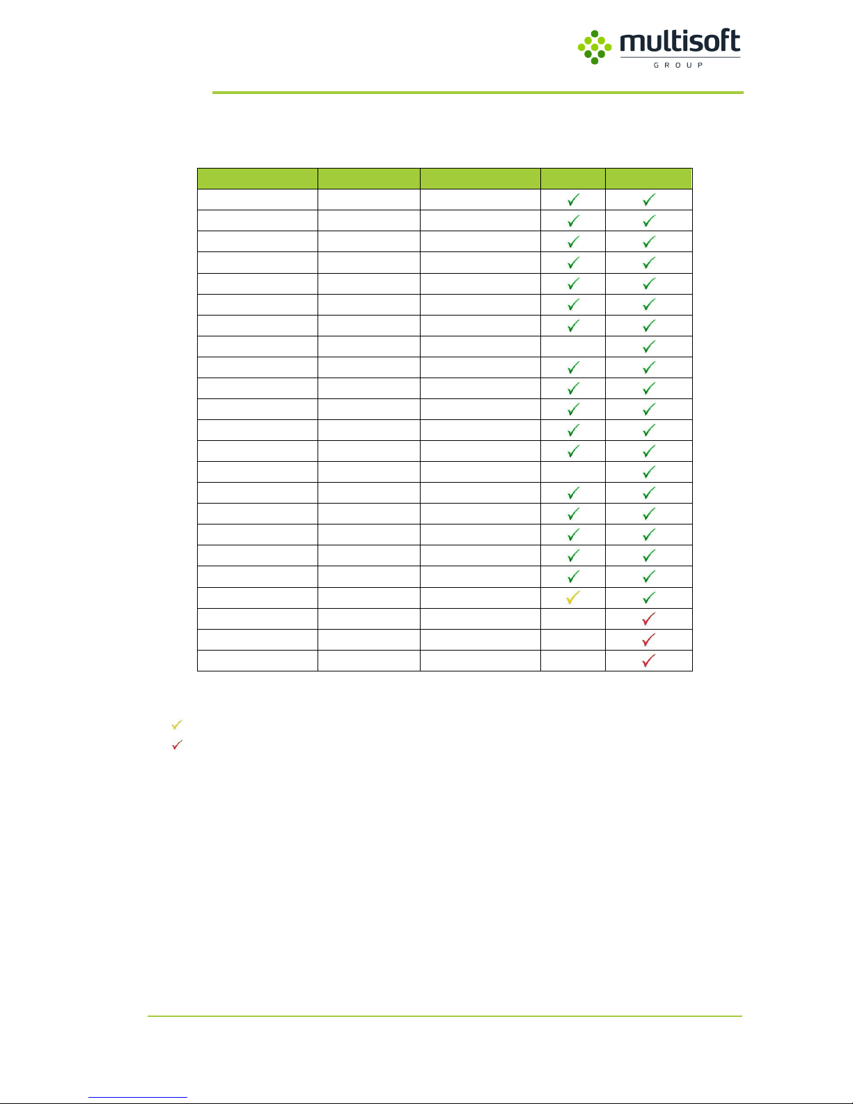
Table 4. Video Grabber VGA / DVI - Supported resolutions table
- It’s required to set CVT reduced blank in driver’s settings.
- DVI Dual Link Cable is required.
 Loading...