

Page 1

OPERATION MANUAL
SERIES
WSHE/A SERIES
VIBRATORY TRUSS SCREED
(HONDA GX270UT2QA2 9HP
GX340UT2QAP2 11HP GASOLINE ENGINES)
Revision #0 (05/22/12)
The original manual copy is in American English.
To find the latest revision of this
publication, visit our website at:
www.multiquip.com
THIS MANUAL MUST ACCOMPANY THE EQUIPMENT AT ALL TIMES.
PN: 36870
Page 2

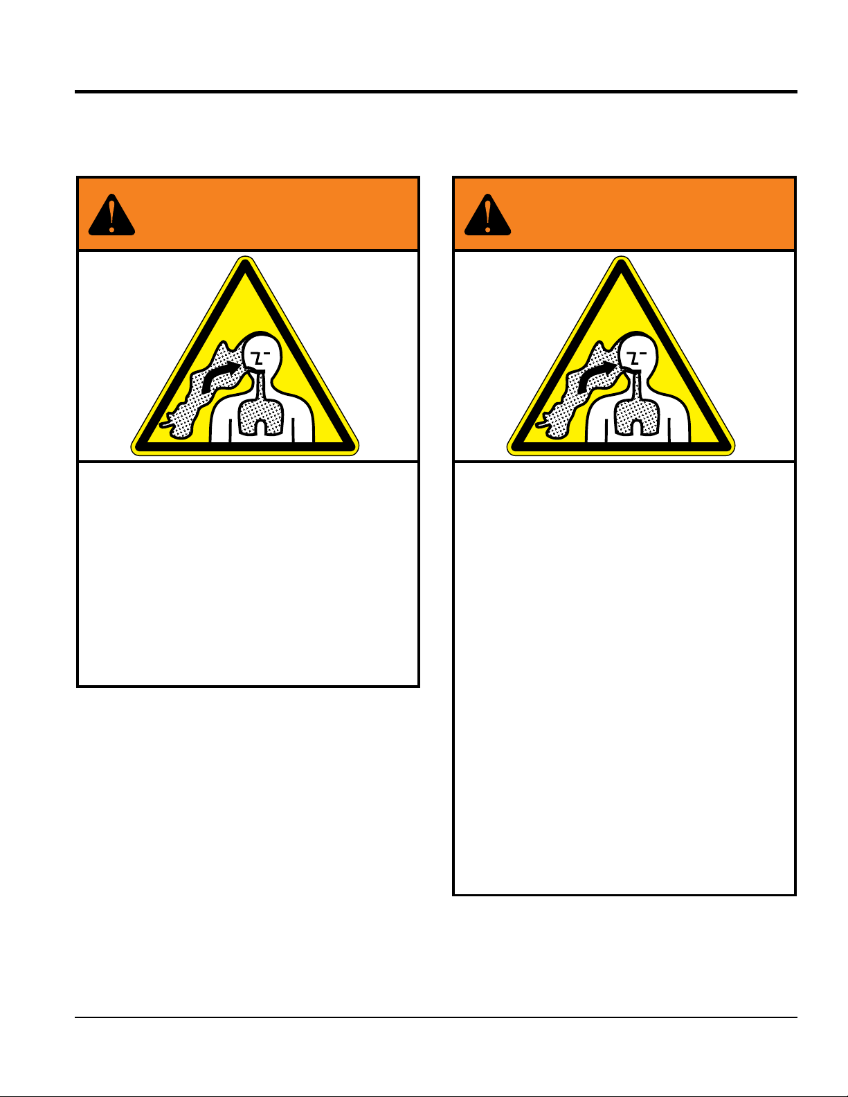
FUEL AND CHEMICAL EXPOSURE WARNINGS
Gasoline engine exhaust and some of
its constituents, and some dust
created by power sanding, sawing,
g r i n d i n g , d r i l l i n g a n d o t h e r
con s truct i on activ i ties con t ain
chemicals know to cause cancer, birth
defects and other reproductive harm.
Someexamples ofthesechemicals are:
Lead from lead-based paints
Crystalline silica from bricks
Cement and other masonry products
Arsenic and chromium from chemically
treated lumber
Your risk from these exposures varies,
depending on how often you do this
type of work. To reduce your exposure
to these chemicals: work in a
well-ventilated area, and work with
approved safety equipment, such as
dust masks that are specially designed
to filter out microscopic particles.
ALWAYS
PAGE 2 — WSHE/A VIBRATORY TRUSS SCREED • OPERATION MANUAL — REV. #0 (05/22/12)
Page 3
SILICOSIS/RESPIRATORY WARNINGS
WARNING
SILICOSIS WARNING RESPIRATORY HAZARDS
Grinding/cutting/drilling of masonry, concrete, metal and
other materials with silica in their composition may give
off dust or mists containing crystalline silica. Silica is a
basic component of sand, quartz, brick clay, granite and
numerous other minerals and rocks. Repeated and/or
substantial inhalation of airborne crystalline silica can
cause serious or fatal respiratory diseases, including
silicosis. In addition, California and some other
authorities have listed respirable crystalline silica as a
substance known to cause cancer. When cutting such
materials, always follow the respiratory precautions
mentioned above.
WARNING
Grinding/cutting/drilling of masonry, concrete, metal and
other materials can generate dust, mists and fumes
containing chemicals known to cause serious or fatal
injury or illness, such as respiratory disease, cancer,
birth defects or other reproductive harm. If you are
unfamiliar with the risks associated with the particular
process and/or material being cut or the composition of
the tool being used, review the material safety data
sheet and/or consult your employer, the material
manufacturer/supplier, governmental agencies such as
OSHA and NIOSH and other sources on hazardous
materials. California and some other authorities, for
instance, have published lists of substances known to
cause cancer, reproductive toxicity, or other harmful
effects.
Control dust, mist and fumes at the source where
possible. In this regard use good work practices and
follow the recommendations of the manufacturers or
suppliers, OSHA/NIOSH, and occupational and trade
associations. Water should be used for dust
suppression when wet cutting is feasible. When the
hazards from inhalation of dust, mists and fumes cannot
be eliminated, the operator and any bystanders should
always wear a respirator approved by NIOSH/MSHA for
the materials being used.
WSHE/A VIBRATORY TRUSS SCREED • OPERATION MANUAL — REV. #0 (05/22/12) — PAGE 3
Page 4

WSHE/A Vibratory
Truss Screed
Fuel And Chemical Exposure Warnings .................. 2
Silicosis/Respiratory Warnings ................................ 3
Table Of Contents .................................................... 4
Training Checklist .................................................... 6
Daily Pre-Operation Checklist ................................. 7
Safety Information ..............................................8-12
Specifications ...................................................13-15
Lifting Procedure ................................................... 16
Transporting Procedure ......................................... 17
General Information .......................................... 18-20
Components ..................................................... 21-22
Accessories ........................................................... 23
Engine Components .............................................. 24
Inspection ......................................................... 25-26
Assembly .......................................................... 27-33
Operation .......................................................... 34-35
Maintenance ..................................................... 36-40
Troubleshooting ................................................ 41-42
TABLE OF CONTENTS
NOTICE
Specifications are subject to change without notice.
PAGE 4 — WSHE/A VIBRATORY TRUSS SCREED • OPERATION MANUAL — REV. #0 (05/22/12)
Page 5

NOTES
WSHE/A VIBRATORY TRUSS SCREED • OPERATION MANUAL — REV. #0 (05/22/12) — PAGE 5
Page 6

TRAINING CHECKLIST
Training Checklist
No, Description OK? Date
1
2
3 Fuel system, refueling procedure.
4
5 Emergency stop procedures.
6 Startup of machine, engine choke
7 Alignment of blades
8 Concrete fi nishing techniques.
9 Shutdown of machine.
10 Lifting of machine .
11 Assembly of truss sections
Read operation manual
completely.
Machine layout, location of
components, checking of engine
oil levels.
Operation of controls (machine
not running).
12 Winch operation.
13 Cleanup procedures.
16 Machine transport and storage.
PAGE 6 — WSHE/A VIBRATORY TRUSS SCREED • OPERATION MANUAL — REV. #0 (05/22/12)
Page 7

DAILY PRE-OPERATION CHECKLIST
Daily Pre-Operation Checklist
1 Engine oil level
2 Bearing lubrication
3 Condition of blades
4 Blade alignment
5 Drive shaft alignment
WSHE/A VIBRATORY TRUSS SCREED • OPERATION MANUAL — REV. #0 (05/22/12) — PAGE 7
Page 8
SAFETY INFORMATION
Do not operate or service the equipment before reading
Potential hazards associated with the operation of this
the entire manual. Safety precautions should be followed
at all times when operating this equipment.
Failure to read and understand the safety
messages and operating instructions could
result in injury to yourself and others.
SAFETY MESSAGES
The four safety messages shown below will inform you
about potential hazards that could injure you or others. The
safety messages specifi cally address the level of exposure
to the operator and are preceded by one of four words:
DANGER, WARNING, CAUTION or NOTICE.
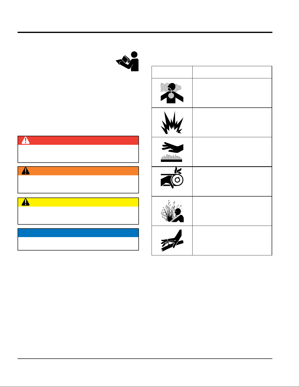
SAFETY SYMBOLS
DANGER
Indicates a hazardous situation which, if not avoided,
WILL result in DEATH or SERIOUS INJURY.
WARNING
Indicates a hazardous situation which, if not avoided,
COULD result in DEATH or SERIOUS INJURY.
equipment will be referenced with hazard symbols which
may appear throughout this manual in conjunction with
safety messages.
Symbol Safety Hazard
Lethal exhaust gas hazards
Explosive fuel hazards
Burn hazards
Rotating parts hazards
CAUTION
Indicates a hazardous situation which, if not avoided,
COULD result in MINOR or MODERATE INJURY.
NOTICE
Addresses practices not related to personal injury.
Pressurized fluid hazards
Hydraulic fluid hazards
PAGE 8 — WSHE/A VIBRATORY TRUSS SCREED • OPERATION MANUAL — REV. #0 (05/22/12)
Page 9
GENERAL SAFETY
NOTICE
This equipment should only be operated by trained and
Whenever necessary, replace nameplate, operation and
accident due to equipment modifi cations. Unauthorized
recommended by Multiquip for this equipment. Damage
keep
Also, know the phone numbers
fi re department.
SAFETY INFORMATION
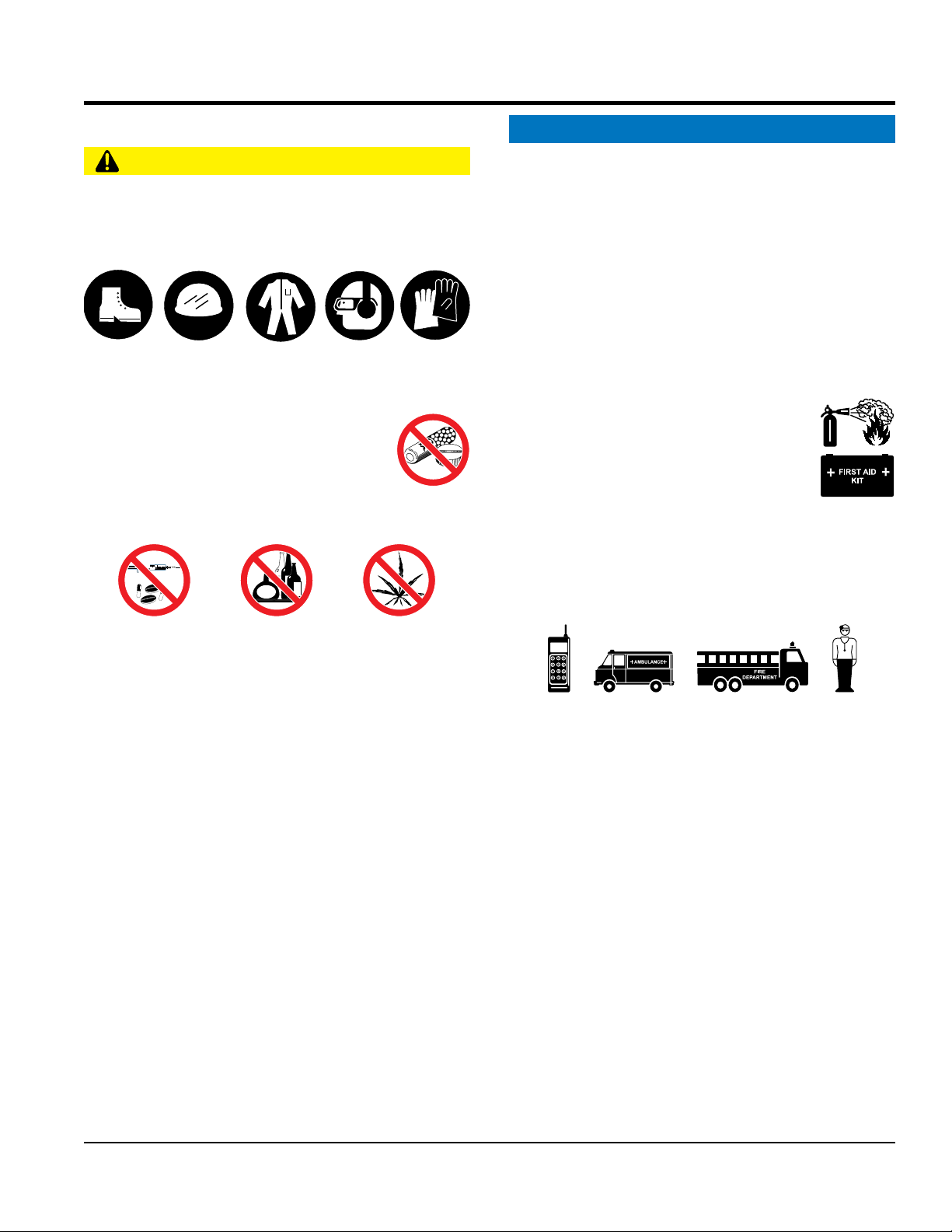
CAUTION
NEVER operate this equipment without proper protective
clothing, shatterproof glasses, respiratory protection,
hearing protection, steel-toed boots and other protective
devices required by the job or city and state regulations.
Avoid wearing jewelry or loose fi tting clothes that may
snag on the controls or moving parts as this can cause
serious injury.
NEVER operate this equipment when not
feeling well due to fatigue, illness or when
under medication.
NEVER operate this equipment under the
infl uence of drugs or alcohol.
ALWAYS clear the work area of any debris, tools, etc.
that would constitute a hazard while the equipment is
in operation.
qualifi ed personnel 18 years of age and older.
safety decals when they become diffi cult read.
Manufacturer does not assume responsibility for any
equipment modifi cation will void all warranties.
NEVER use accessories or attachments that are not
to the equipment and/or injury to user may result.
ALWAYS know the location of the nearest
fi re extinguisher.
ALWAYS know the location of the nearest
fi rst aid kit.
ALWAYS know the location of the nearest phone or
a phone on the job site.
of the nearest ambulance, doctor and
This information will be invaluable in the case of an
emergency.
No one other than the operator is to be in the working
area when the equipment is in operation.
DO NOT use the equipment for any purpose other than
its intended purposes or applications.
WSHE/A VIBRATORY TRUSS SCREED • OPERATION MANUAL — REV. #0 (05/22/12) — PAGE 9
Page 10

SCREED SAFETY
NOTICE
keep the machine in proper running condition.
store equipment properly when it is not being
used. Equipment should be stored in a clean, dry location
out of the reach of children and unauthorized personnel.
engine is hot. The possibility of hot oil exists which could
run engine without an air fi lter or with a dirty air
fi lter. Severe engine damage may occur. Service air fi lter
SAFETY INFORMATION
DANGER
Engine fuel exhaust gases contain poisonous carbon
monoxide. This gas is colorless and odorless, and can
cause death if inhaled.
The engine of this equipment requires an adequate free
fl ow of cooling air. NEVER operate this equipment in any
enclosed or narrow area
where free fl ow of the air is
restricted. If the air fl ow is
restricted it will cause injury
to people and property and
serious damage to the
equipment or engine.
NEVER operate the equipment in an explosive
atmosphere or near combustible materials. An
explosion or fi re could result causing severe
bodily harm or even death.
WARNING
If applicable, NEVER use your hand to fi nd
hydraulic leaks. Use a piece of wood or
cardboard. Hydraulic fl uid injected into the
skin must be treated by a knowledgable
physician immediately or severe injury or
death can occur.
DANGEROUS
GAS FUMES
ALWAYS
Fix damage to machine and replace any broken parts
immediately.
ALWAYS
ENGINE SAFETY
WARNING
DO NOT pl ace han ds or fin gers inside engin e
compartment when engine is running.
NEVER operate the engine with heat shields or
guards removed.
Keep fi ngers, hands hair and clothing away
from all moving parts to prevent injury.
DO NOT remove the engine oil drain plug while the
cause severe scalding.
CAUTION
NEVER touch the hot exhaust manifold,
muffl er or cylinder. Allow these parts to cool
before servicing equipment.
ALWAYS keep clear of rotating or moving
parts while operating the screed.
NEVER disconnect any emergency or safety devices.
These devices are intended for operator safe ty.
Disconnection of these devices can cause severe injury,
bodily harm or even death. Disconnection of any of these
devices will void all warranties.
CAUTION
NEVER allow passengers or riders on the screed during
operation.
NEVER lubricate components or attempt service on a
running machine.
PAGE 10 — WSHE/A VIBRATORY TRUSS SCREED • OPERATION MANUAL — REV. #0 (05/22/12)
NOTICE
NEVER
frequently to prevent engine malfunction.
NEVER tamper with the factory settings
of the engine or engine governor. Damage
to the engine or equipment can result
if operating in speed ranges above the
maximum allowable.
Page 11
FUEL SAFETY
DANGER
A strap or chain can be attached to these hooks, allowing
a forklift or crane to lift the screed up onto and off of a slab
of concrete. The strap or chain should have a minimum
of 2,000 pounds (1,000 kg) lifting capacity and the lifting
make
sure the trailer that supports the screed and the towing
Make sure the hitch and coupling of the towing vehicle
NEVER
tow a trailer with defective hitches, couplings, chains, etc.
Trailer tires should be infl ated to 50 psi cold.
SAFETY INFORMATION
DO NOT start the engine near spilled fuel or combustible
fl uids. Fuel is extremely fl ammable and its vapors can
cause an explosion if ignited.
ALWAYS refuel in a well-ventilated area, away from
sparks and open fl ames.
ALWAYS use extreme caution when working with
fl ammable liquids.
DO NOT fi ll the fuel tank while the engine is running
or hot.
DO NOT overfi ll tank, since spilled fuel could ignite if it
comes into contact with hot engine parts or sparks from
the ignition system.
Store fuel in appropriate containers, in well-ventilated
areas and away from sparks and fl ames.
NEVER use fuel as a cleaning agent.
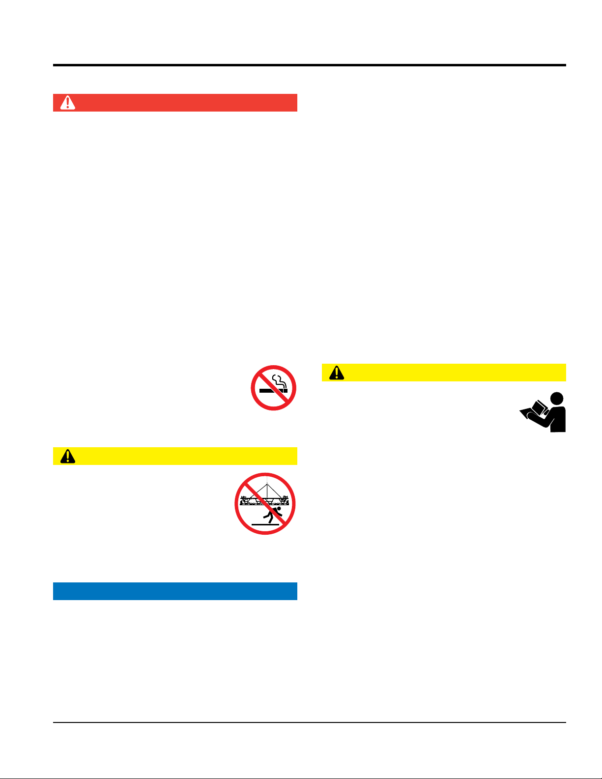
DO NOT sm oke aroun d or near the
equipment. Fire or explosion could result
from fuel vapors or if fuel is spilled on a
hot engine.
TRANSPORTING SAFETY
NEVER allow any person or animal to
stand underneath the equipment while
lifting.
NEVER lift or transport screed with
personnel standing on the screed.
Use proper heavy lifting procedures when lifting the
screed.
NOTICE
Machine can be transported on fl atbed truck of proper
weight capacity.
The easiest way to lift the screed is to attach lifting hooks
to the screed frame. Lifting hooks should be placed at
equal distances from each end of the screed.
CAUTION
device must be capable of lifting at least this amount.
Always make sure crane or lifting device has been
properly secured to the lifting hooks on the equipment.
ALWAYS shutdown engine before transporting.
NEVER lift the equipment while the engine is running.
Tighten fuel tank cap securely and close fuel cock to
prevent fuel from spilling.
Use adequate lifting cable (wire or rope) of suffi cient
strength.
DO NOT lift machine to unnecessary heights.
ALWAYS tie down equipment during transport by
securing the equipment with rope.
TOWING SAFETY
CAUTION
Check with your local county or state safety
towing regulations, in addition to meeting
Department of Transportation (DOT)
Safety Towing Regulations, before towing
your screed.
In order to reduce the possibility of an accident while
transporting the screed on public roads, ALWAYS
vehicle are mechanically sound and in good operating
condition.
ALWAYS shutdown engine before transporting
are rated equal to, or greater than the trailer “gross
vehicle weight rating.”
ALWAYS inspect the hitch and coupling for wear.
Check the tire air pressure on both towing vehicle and
trailer.
Also check the tire tread wear on both vehicles.
WSHE/A VIBRATORY TRUSS SCREED • OPERATION MANUAL — REV. #0 (05/22/12) — PAGE 11
Page 12

ALWAYS make sure the trailer is equipped with a safety
DO NOT pour waste or oil directly onto the ground, down
recommended that the screed frame and all other metal
Recyclers and manufacturers alike promote the process
This engine has been certifi ed to meet US EPA Evaporative
emission system by unauthorized personnel without proper
training could damage the equipment or create an unsafe
Additionally, modifying the fuel system may adversely affect
evaporative emissions, resulting in fi nes or other penalties.
The emission control label is an integral part of the emission
If a replacement emission label is needed, please contact
SAFETY INFORMATION
chain.
ALWAYS properly attach trailer’s safety chains to towing
vehicle.
ALWAYS make sure the vehicle and trailer directional,
backup, brake and trailer lights are connected and
working properly.
DOT Requirements include the following:
• Connect and test electric brake operation.
• Secure portable power cables in cable tray with tie
wraps.
The maximum speed for highway towing is 55 MPH unless
posted otherwise. Recommended off-road towing is not to
exceed 15 MPH or less depending on type of terrain.
Avoid sudden stops and starts. This can cause skidding,
or jack-knifi ng. Smooth, gradual starts and stops will
improve towing.
Avoid sharp turns to prevent rolling.
Trailer should be adjusted to a level position at all times
when towing.
Raise and lock trailer wheel stand in up position when
towing.
a drain or into any water source.
Contact your country's Department of
Public Works or recycling agency in your
area and arrange for proper disposal of
any electrical components, waste or oil
associated with this equipment.
When the life cycle of this equipment is over, it is
parts be sent to a recycling center.
Metal recycling involves the collection of metal from
discarded products and its transformation into raw
materials to use in manufacturing a new product.
of recycling metal. Using a metal recycling center
promotes energy cost savings.
NOTICE
The gasoline engine used in this equipment has been
designed to reduce harmful levels of carbon monoxide
(CO), hydrocarbons (HC) and nitrogen oxides (NOx)
contained in diesel exhaust emissions.
emissions requirements in the installed confi guration.
Attempting to modify or make adjustments to the engine
Place chock blocks underneath wheel to prevent rolling
while parked.
Place support blocks underneath the trailer’s bumper to
prevent tipping while parked.
Use the trailer’s swivel jack to adjust the trailer height to
a level position while parked.
ENVIRONMENTAL SAFETY/DECOMMISSIONING
NOTICE
Decommissioning is a controlled process used to safely
retire a piece of equipment that is no longer serviceable.
If the equipment poses an unacceptable and unrepairable
safety risk due to wear or damage or is no longer cost
effective to maintain (beyond life-cycle reliability) and is to
be decommissioned (demolition and dismantlement),be
sure to follow rules below.
condition.
Emission Control Label
system and is strictly controlled by regulations.
The label must remain with the engine for its entire life.
your authorized Honda Engine Distributor.
PAGE 12 — WSHE/A VIBRATORY TRUSS SCREED • OPERATION MANUAL — REV. #0 (05/22/12)
Page 13

SPECIFICATIONS
Table 1. Engine-Powered Screeds
Recommended Slump 3 in (76 mm)
Max. Concrete Depth 8 in (203 mm)
Max Screed Width 65 ft (19.8 m)
Model Description Weight lb. (kg)
WSHE20 2 foot (.61 m) truss with eccentric shaft vibration 46 (20)
WSHE25 2.5 foot (.76 m) truss with eccentric shaft vibration 50 (23)
WSHE50 5 foot (1.5 m) truss with eccentric shaft vibration 95 (43)
WSHE75 7.5 foot (2.3 m) truss with eccentric shaft vibration 136 (62)
WSHE100 10 foot (3.1 m) truss with eccentric shaft vibration 190 (86)
Accessories
Model Description Weight lb. (kg)
WSHEH End handles (two each) 54 (27)
WSHW Manual Winches, set of two 42 (19)
WSHSPW(L) Self-propelled winch (left side), includes 2.5 foot truss 105 (48)
WSHSPW(R) Self-propelled winch (right side), includes 2.5 foot truss 105 (48)
WSHRBE Reinforcement bracket, engine screed 6 (2.7)
WSKITAEB Adjustable end brackets, set of two, skid type 24 (11)
WSKITAEBR Adjustable end brackets, set of two, roller type 26 (12)
WSHEKITUJ Invert/crown kit, for adjustments up to ¼-inch per foot 22 (10)
WSHEIC Invert/crown kit, for adjustments in excess of ¼-inch per foot 98 (41)
WSHEKIT9H 9 HP Engine Kit 112 (51)
WSHE50KIT9H
WSHEKIT11H 11 HP Engine Kit 112 (51)
WSHE50KIT11H
36243 Truss screed dolly 50 (23)
9 HP Engine Kit
installed on 5 foot truss section
11 HP Engine Kit
installed on 5 foot truss section
207 (94)
207 (94)
WSHE/A VIBRATORY TRUSS SCREED • OPERATION MANUAL — REV. #0 (05/22/12) — PAGE 13
Page 14

SPECIFICATIONS
Table 2. Air-Powered Screeds
Recommended Slump 2 in + (51 mm +)
Max. Concrete Depth 12 in (305 mm)
Max Screed Width 65 ft (19.8 m)
Model Description Weight lb. (kg)
WSHA20 2 foot (.61 m) truss 45 (20)
WSHA25 2.5 foot (.76 m) truss with 2 air piston vibrators 50 (23)
WSHA50 5 foot (1.5 m) truss with 4 air piston vibrators 95 (43)
WSHA75 7.5 foot (2.3 m) truss with 6 air piston vibrators 136 (62)
WSHA100 10 foot (3.1 m) truss with 8 air piston vibrators 190 (86)
Accessories
Model Description Weight lb. (kg)
WSHAH End handles (two each) and air regulator kit 54 (27)
WSHW Manual Winches, set of two 42 (19)
WSHRBA Reinforcement bracket, air screed 6 (2.7)
WSKITAEB Adjustable end brackets, set of two, skid type 24 (11)
WSKITAEBR Adjustable end brackets, set of two, roller type 26 (12)
WSHAIC Invert/crown kit, for adjustments in excess of ¼-inch per foot 62 (28)
36243 Truss screed dolly 50 (23)
Table 3. Noise and Vibration Emissions for WSHEKIT9H
Guaranteed ISO 11201:2010 Based
Sound Pressure Level at Operator Station in dB(A)
Guaranteed ISO 3744:2010 Based
Sound Power Level in dB(A)
88
105
NOTES:
1. Sound Pressure and Power Levels are “A” weighted Measures per ISO 226:2003 (ANSI S1.4-1981). They are measured with the operating
condition of the machine which generates the most repeatable but highest values of the sound levels. Under normal circumstances, the sound
level will vary depending on the condition of the material being worked upon.
PAGE 14 — WSHE/A VIBRATORY TRUSS SCREED • OPERATION MANUAL — REV. #0 (05/22/12)
Page 15

SPECIFICATIONS
Table 4. Engine Specifications/Dimensions
Model Honda GX270UT2QA2 Engine Honda GX340UT2QAP2 Engine
Type
Bore X Stroke 3.0 in. X 2.3 in. (77 mm x 58 mm) 3.4 in. X 2.5 in. (88 mm x 64 mm)
Displacement 16.4 cu-in. (270 cc) 23.7 cu-in. (389 cc)
Max. Output 9.0 H.P. @ 3600 RPM 11.0 H.P. @ 3600 RPM
Fuel Tank Capacity Approx. 1.95 U.S. Gallons (6.0 Liters) Approx. 1.95 U.S. Gallons (6.0 Liters)
Fuel Unleaded Gasoline Unleaded Gasoline
Lube Oil Capacity 1.06 qt. (1.1 liters) 1.06 qt. (1.1 liters)
Oil Type
Speed Control Method Centrifugal Fly-weight Type Centrifugal Fly-weight Type
Cooling System Forced Air Forced Air
Starting Method Recoil Start Recoil Start
Spark Plug Type BPR6ES NGK BPR6ES NGK
Spark Plug Gap 0.028-0.031 in. (0.70 - 0.80 mm) 0.028-0.031 in. (0.70 - 0.80 mm)
Dimension (L x W x H) 15.0 x 16.8 X 16.6 in. (381 X 428 X 422 mm) 15.9 x 18.1 X 17.6 in. (406 X 460 X 448 mm)
Dry Net Weight 55.1 lbs (25 Kg.) 69.8 lbs (31.7 Kg.)
Air-cooled 4 stroke, Single Cylinder, OHV,
Horizontal Shaft Gasoline Engine
4-Stroke API, SF or SG
SAE 10W-30 General Use
Air-cooled 4 stroke, Single Cylinder, OHV,
Horizontal Shaft Gasoline Engine
4-Stroke API, SF or SG
SAE 10W-30 General Use
WSHE/A VIBRATORY TRUSS SCREED • OPERATION MANUAL — REV. #0 (05/22/12) — PAGE 15
Page 16

LIFTING PROCEDURE
LIFTING THE SCREED
The following procedure and Figure 1 describe how to lift
the vibratory screed.
WARNING
NEVER lift the screed to unnecessary heights.
ALWAYS make sure that no one is standing underneath
the screed while it is being lifted.
1. Attach the U-shaped hanger and associated hardware
to the top of each truss frame section as shown in
Figure 1. Tighten hanger securely so that it will not slip.
2. Utilize a spreader bar of proper length and lifting
capacity. Secure lifting straps from both ends of the
spreader bar to the attached lifting hangers.
3. Connect lifting cables from the spreader bar to the
lifting hook of a crane or forklift. Ensure that the lifting
hook and chain are of appropriate lifting capacity.
4. Use crane or forklift to hoist screed onto a flatbed truck
for transporting or onto the form for screeding.
FRONT
Figure 1. Lifting the Screed
PAGE 16 — WSHE/A VIBRATORY TRUSS SCREED • OPERATION MANUAL — REV. #0 (05/22/12)
Page 17

TRANSPORTING PROCEDURE
TRANSPORTING THE SCREED
Place the screed on a flatbed truck during transportation as shown in Figure 2. Attach suitable tie-down straps to the screed
to secure it to the truck. Route tie-down straps over truss frame sections as required.
\
TIE-DOWN
STRAPS
TYPICAL TIE-DOWN APPLICATION
Figure 2. Screed Tie-Down Points
WSHE/A VIBRATORY TRUSS SCREED • OPERATION MANUAL — REV. #0 (05/22/12) — PAGE 17
Page 18

WINCH
GENERAL INFORMATION
2x4 FORMS
FORM STAKES
CONCRETE
TRAVEL DIRECTION
BULL FLOAT
BLADE
Figure 3. Vibratory Screed Application
WINCH CABLE
2 BLADES
PAGE 18 — WSHE/A VIBRATORY TRUSS SCREED • OPERATION MANUAL — REV. #0 (05/22/12)
Page 19

GENERAL INFORMATION
(76 MM)
DIRECTION
ENGINE SIDE
Multiquip vibratory truss screeds are used for leveling
pavement and industrial floors. They are available in airpowered and engine-driven configurations. The vibratory
truss screeds provide dependable performance on job
after job. Its modular design allows the ability to configure
the screed by adding or removing sections as needed.
Figure 3 represents a typical vibratory screed application.
HEAVY-DUTY STEEL CONSTRUCTION
The Multiquip vibratory truss screed uses a triangular frame
design (Figure 4), built to take the abuse of rough handling
on a jobsite. Unlike the lightweight aluminum screed, the
steel screed will hold its precise shape better on long pours
and over a longer period of time. Additionally, the heavier
steel screed will stay down on the forms and will not ride up
during a pour. This vibratory screed weighs approximately
14 pounds per foot.
STEEL TRUSS DESIGN
The steel construction keeps the screed from riding up on
stiff concrete mix designs.
The vibratory truss screed features top pipe manufactured
from schedule 80 steel and features 16 TPI thread to
provide fine grade control should crowns or inverts be
required.
FOUR DIFFERENT LENGTHS
Multiquip Vibratory Screeds come in four lengths: 2-1/2 ft.,
5 ft., 7-1/2 ft. and 10 ft. sections.
NOTICE
It is best to allow a minimum overhang past the forms
(6" to 12" is ideal).
STANDARDIZATION (AIR AND ENGINE DRIVEN)
Multiquip uses the same frame for both the air and engine
driven screeds. The top pipe is drilled and tapped to allow
air connections for the air vibrators.
SCREED BLADES
The screed blades are constructed of 10-gauge galvanized
steel for rust resistance and maximum durability. The front
blades consist of two 1-1/2" high x 2" wide angles. This
gives the screed blades 2-1/2 inches of concrete surcharge
and 4 inches of screed surface. The rear (bull float) blade is
a single blade 2-1/2" wide. A total of 7 inches of concrete
surface contact is provided by the screed.
BOLT-ON BLADE DESIGN
The WSHE/A vibratory truss screeds features a bolton blade design to allow easy replacement of worn or
damaged blades.
BULL FLOAT
BLADES
OF SCREED
3/8" TRUSS ROD
VIBRATION
DAMPENING
3"
3/8" X 1-1/2"
BOTTOM TRUSS
SUPPORT
12-3/8"
(314 MM)
OF TRAVEL
SCHEDULE 80
TOP PIPE
TRUSS RODS
Figure 4. Screed Cross Section
1/2" DIA.
STRIKE-OFF
(51 MM)
BLADES
2"
16"
(406 MM)
AIR-POWERED SCREED
Air vibrators offer high frequency (up to 9500 vibrations per
minute at 60 PSI) for excellent consolidation of low slump
mixes. The screed is capable of striking off slabs up to 11
inches thick (performance may vary according to mix design
and job requirements).
The vibrators are placed on 30-inch centers and located
at both front and rear blades for uniform vibration. Air
consumption is approximately 4CFM for each vibrator at
60 PSI. Crowns/Inverts up to 1/4" per foot are attainable
without an optional kit.
ENGINE DRIVEN SCREED
The engine-driven screed has an eccentric shaft design
that produces 8,000 vibration cycle nodes per minute. It
is ideal for slab, bridge, and highway applications. The
engine-driven screed is powered by either a 9 HP or 11 HP
Honda engine. Engine kits are available factory installed on
5-foot truss sections for reduced setup time at the job site.
Winch options include manual or self-propelled models.
WSHE/A VIBRATORY TRUSS SCREED • OPERATION MANUAL — REV. #0 (05/22/12) — PAGE 19
Page 20

GENERAL INFORMATION
Self-propelled models are each mounted on a 2.5-foot
section of the screed. Crowns/Inverts may be obtained
with optional kits.
ROTATING ECCENTRIC SHAFT (RES)
VIBRATORY SCREED
The rotating eccentric shaft produces over 8000 VPM. The
shaft is built of 3/4" diameter, high strength steel with 1-3/8"
diameter dual eccentrics bolted on 30" centers. The shaft
is supported by heavy-duty, solid-mounted pillow block
bearings (the bearings are greaseable and provide long
life and solid transmission of vibration through the lower
frame and blades into the concrete).
PROPELLING THE SCREED
Several options are available for moving the screed during
a pour.
1. Manual Winches — Heavy Duty 2500 lb., 2 speed
winches with 100 feet of 1/8" aircraft cable can be
located on either end of the screed or with the addition
of a pulley kit, both sides of the screed can be winched
from on side.
2. Hydraulic Winches — By adding a pulley to the
rotating eccentric shaft, power can be harnessed
to drive a small Parker hydraulic pump. This pump
provides power to an Eaton drive motor driving the
winches located on either side of the screed. The speed
of the winch is variable from 0 to 12 feet per minute.
INVERTS AND CROWNS
Multiquip Vibratory Screeds can be aligned to form inverts
or crowns with the use of special Invert/Crown Brackets,
Flex-Joint or U-Joint kits. Crowns of up to 1/4-inch per foot
are considered normal. Most highway specifications call for
1/4-inch per foot or 2% crowns. (.25 inches per 12 inches)
SCREED WIDTH
The recommended maximum length is 65 feet for both
air and engine driven screeds. With lengths over 35 feet,
the engine should be mounted on a center section of the
screed. This increases efficiency and equalizes the load
on the driveshaft.
SLAB THICKNESS
Like soil compaction, slab thickness is variable. Maximum
slab thickness depends on the concrete mix, type of forms
used, travel speed and other variables. The Rule of Thumb
is: 8 to 9 inches for the RES type and up to 12 inches for
the air screed.
RATE OF TRAVEL
The rate of travel for the screed varies. The men working
the concrete should maintain a slight discharge of concrete
in front of the screed. (DO NOT allow concrete to flow over
the screed blades by more than 2-1/2".) As you move the
screed forward, you should be getting a nice, creamy
surface behind the bull float blade. Increase the travel speed
until the surface deteriorates and then slow down slightly
to achieve maximum travel speed.
COMMONLY ASKED QUESTIONS:
1. “How wide can I go with the vibratory screed?”
Recommended maximum length is 65 feet for both air
and engine driven screeds. With lengths over 20 feet,
the engine should be mounted on a center section of
the screed. This increases efficiency and equalizes the
load on the driveshaft.
2. “What is the maximum slab thickness I can expect to
effectively consolidate?”
Like soil compaction, this is variable. It depends on
the concrete mix, type of forms used, travel speed and
other variables. The rule of thumb is: 8 to 9 inches for
the RES type and up to 12 inches for the air screed.
3. “At what rate of travel should I work the screed?”
It varies. The men working the concrete should maintain
a slight discharge of concrete in front of the screed.
(Do not allow concrete to flow over the screed blades
by more than 2-1/2".) As you move the screed forward,
you should be getting a nice, creamy surface behind
the bull float blade. Increase the travel speed until the
surface deteriorates and then slow down slightly to
achieve maximum travel speed.
PAGE 20 — WSHE/A VIBRATORY TRUSS SCREED • OPERATION MANUAL — REV. #0 (05/22/12)
Page 21

COMPONENTS
16
15
13
18
15
17
4
3
9
7
8
3
12
5
13
11
6
1
2
14
Figure 5. WSHE Components
Figure 5 and Figure 6 show the location of the basic
components of a 10-foot WSHE/A screed. The function of
each component is described below.
1. Rear (Bull Float) Blade — 2-1/2" high x 3" wide blade,
constructed of 10-gauge galvanized steel.
2. Front Blades — two 2-1/2" high x 2" wide blades,
constructed of 10-gauge galvanized steel.
3. Truss Frame — Available in four lengths: 2-1/2 ft., 5 ft.,
7-1/2 ft. and 10 ft. (two 5 ft. sections illustrated above).
Each frame section features a heavy-duty schedule 80
top pipe for structural integrity.
4. Turnbuckle — Connects two truss sections together.
Fine threads allow controlled adjustment for slight
crown or invert configurations.
1011
5. Blade Connector — Connects two blades together.
Bolt-on blade design allows for easy replacement of
worn or damaged blades.
6. Rotating Eccentric Shaft — Produces over 8000
VPM, built of 3/4" diameter, high strength steel.
7. Pillow Block Bearings — Support rotating shaft.
8. Eccentric Weights — Bolted onto rotating shaft to
produce vibration.
9. Engine — Honda GX270 or GX340 engine drives the
rotating shaft.
10. Guard Tube — Covers the rotating shaft to prevent
equipment damage and operator injury.
11. Tube Mounts — Secure guard tubes to the truss frame.
12. Belt Guard — Covers the rotating V-belt to prevent
operator injury.
WSHE/A VIBRATORY TRUSS SCREED • OPERATION MANUAL — REV. #0 (05/22/12) — PAGE 21
Page 22

COMPONENTS
16
15
20
13
21
22
23
15
17
4
18
3
3
19
5
13
1
2
14
Figure 6. WSHA Components
13. End Handle Section — Two end handle sections
required for screed assembly.
14. End Handle — Allows lifting of screed onto and off of slab.
15. Manual Winch — Heavy duty 2500 lb, 2 speed winch
with 100 feet of 1/8" aircraft cable located on one or
both ends of the screed. Self-propelled hydraulic winch
option minimizes labor and offers speeds from 0 to
12 feet per minute.
16. Winch Handle — Rotate handle to facilitate screed
movement.
17. Cable Hook — Fastened to stationary point in line of
screed travel.
18. Lifting Hanger — One hanger located on both ends
of the screed.
19. Air Vibrator — Naval bronze piston vibrators produce
9,500 vibrations per minute.
20. Oil Mist Lubricator — Holds one quart of oil to lubricate
air vibrators. Multiquip recommends SAE 10 wt. nongumming type oil.
21. Air Gauge — Indicates vibrator air pressure.
22. On-Off Valve — Rotate valve to allow air to flow into or
prevent air from entering vibrators.
23. Quick-Disconnect Coupler — Connects screed to air
compressor.
NOTICE
The air vibrator operates at 80 PSI, consuming only 4.5
CFM of air to provide effective consolidation of concrete
without over-vibration.
PAGE 22 — WSHE/A VIBRATORY TRUSS SCREED • OPERATION MANUAL — REV. #0 (05/22/12)
Page 23

ACCESSORIES
Crown
Invert
WSHAIC
Invert/Crown
Kit
Universal Joint,
Top Pipe
Invert
Crown
WSHEIC
Invert/Crown
Kit
7
6
3
Universal Joint,
Rotating Shaft
2
1
Figure 7. Accessories
4
5
WSHE/A VIBRATORY TRUSS SCREED • OPERATION MANUAL — REV. #0 (05/22/12) — PAGE 23
Page 24

ENGINE COMPONENTS
INITIAL SERVICING
The engine (Figure 8) must be checked for proper
lubrication and filled with fuel prior to operation. Refer to the
manufacturer's engine manual for instructions and details
of operation and servicing.
1. Fuel Filler Cap – Remove this cap to add unleaded
gasoline to the fuel tank. Make sure cap is tightened
securely. DO NOT over fill.
DANGER
Add fuel to the tank only when the engine
is stopped and has had an opportunity to
cool down. In the event of a fuel spill, DO
NOT attempt to start the engine until the
fuel residue has been completely wiped up
and the area surrounding the engine is dry.
2. Throttle Lever – Used to adjust engine RPM speed.
This lever is connect to the throttle lever cable located
on the handle bars. Reference throttle cable installation
procedure in this manual.
3. Recoil Starter (pull rope) – Manual-starting method.
Pull the starter grip until resistance is felt, then pull
briskly and smoothly.
4. Fuel Valve Lever – OPEN to let fuel flow, CLOSE to
stop the flow of fuel.
5. Choke Lever – Used in the starting of a cold engine,
or in cold weather conditions. The choke enriches the
fuel mixture.
Figure 8. Engine Controls and Components
6. Air Cleaner – Prevents dirt and other debris from
entering the fuel system. Remove wing-nut on top of
air filter canister to gain access to filter element.
NOTICE
Operating the engine without an air filter, with a
damaged air filter, or a filter in need of replacement
will allow dirt to enter the engine, causing rapid engine
wear.
7. Spark Plug – Provides spark to the ignition system.
Set spark plug gap according to engine manufacturer's
instructions. Clean spark plug once a week.
8. Muffler – Used to reduce noise and emissions. NEVER
touch when hot!
9. Fuel Tank – Fill with unleaded gasoline. Reference
Table 4 for fuel tank capacity. For additional information
refer to Honda engine owner's manual.
10. Dipstick/Oil Filler Cap – Remove this cap to determine
if the engine oil is low. Add oil through this filler port as
recommended in Table 5.
11. Oil Drain Plug – Remove this plug to remove oil from
the engine's crankcase.
12. Engine ON/OFF Switch – ON position permits engine
starting, OFF position stops engine operation.
PAGE 24 — WSHE/A VIBRATORY TRUSS SCREED • OPERATION MANUAL — REV. #0 (05/22/12)
Page 25

INSPECTION
Inspection Screed
1. Read all safety instructions at the beginning of manual.
2. Clean the entire screed, removing dirt and concrete
debris from the truss screed sections.
3. Make sure that the all bolts are secure and will not
vibrate loose.
4. Check for loose set screws on all shaft couplers.
5. Check jam nuts on top pipe to ensue that they are tight
against the top pipe coupler.
6. Check the oil and fuel levels of the engine (for enginedriven screeds).
7. Check bearings for grease (bearings are pre-greased
from the manufacturer.
8. Check winch cables to make sure that they will not
become loose during the screed run.
9. Look over the forms to check for unevenness so that
the screed will not hang up.
Inspection Engine
1. Clean the engine, removing dirt and dust, particularly
the engine cooling air inlet, carburetor and air cleaner.
Engine Oil Check
1. To check the engine oil level, place the screed on
secure level ground with the engine stopped.
2. Remove the dipstick from the engine oil filler hole
(Figure 9) and wipe clean.
Figure 9. Engine Oil Dipstick Removal
3. Insert and remove the dipstick without screwing it into
the filler neck. Check the oil level shown on the dipstick.
4. If the oil level is low (Figure 10), fill to the edge of the
oil filler hole with the recommended oil type as listed
in Table 5. Reference Table 4 for maximum engine oil
capacity.
2. Check the air filter for dirt and dust. If air filter is dirty,
replace air filter with a new one as required.
3. Check carburetor for external dirt and dust. Clean with
dry compressed air.
4. Check engine mounting hardware fastening nuts and
bolts for tightness.
Figure 10. Engine Oil Dipstick (Oil Level)
Table 5. Oil Type
Season Temperature Oil Type
Summer 25°C or Higher SAE 10W-30
Spring/Fall 25°C~10°C SAE 10W-30/20
Winter 0°C or Lower SAE 10W-10
WSHE/A VIBRATORY TRUSS SCREED • OPERATION MANUAL — REV. #0 (05/22/12) — PAGE 25
Page 26

INSPECTION
DANGER
EXPLOSIVE FUEL!
Motor fuels are highly flammable and can
be dangerous if mishandled. DO NOT
smoke while refueling. DO NOT attempt
to refuel the trowel if the engine is hot! or
running.
Fuel Check
1. Visually inspect to see if fuel level is low. If fuel is low,
replenish with unleaded fuel.
2. When refueling, be sure to use a strainer for filtration.
DO NOT top-of f fuel . Wipe up any spilled fuel
immediately.
Pillow Block Bearing Lubrication
1. Each truss section has a set of pillow block bearings
(Figure 11) that will require lubrication. Always make
sure that the bearings are lubricated before each use
of the screed. See maintenance section in this manual
for bearing lubrication intervals..
GREASE
GUN
V-Belt Check
A worn or damaged V-belt (Figure 12) can adversely affect
the performance of the screed (gas driven). If a V-belt is
defective or worn simply replace the V-belt as outlined in
the maintenance section of this manual.
OIL SOAKED
GLAZED
CRACKS
SIDEWALL
WEAR
Figure 12. V-Belt Check
CORD FAILURE
WORN BACK
COVER
BROKEN
MISSING RUBBER
V-Belt Guard Check
Check for damage, loose or missing hardware.
CAP
GREASE
FITTING
Figure 11. Bearing Lubrication
Blade Check
Check for worn or damaged blades (Figure 13). Check to
see if one blade is worn out while the others look new.
Replace any worn blades.
L
R
DAMAGED AREAS
Figure 13. Blade Inspection
PAGE 26 — WSHE/A VIBRATORY TRUSS SCREED • OPERATION MANUAL — REV. #0 (05/22/12)
Page 27

ASSEMBLY
ASSEMBLY
ALWAYS assembled screed on a flat surface that is free of
debris and foreign objects. For best result place screed on
a flat platform during assembly. This will ensure flatness of
the screed blades when assembly is complete.
Things to remember during and after assembly:
• ALWAYS make sure eccentric drive shaft is properly
aligned.
• Make sure eccentric weights are installed correctly.
Reference Figure 35 for correct orientation.
• If eccentric weights are mismatched screed will not
vibrate properly.
• DO NOT overspeed, engine speed must not exceed
3600 RPM.
• NEVER let concrete build on front blade. This condition
causes the screed to be stressed and make turning of
the winch handles difficult.
• DO NOT over vibrate concrete.
• Turn winch handles simultaneously to keep screed
even.
The illustrations referenced in this section describe how
to assemble the vibratory screed. Listed below are the
various assemblies that will have to be assembled. End
Handle Section
Engine Section
Truss Frame Section
Hand Winch Section
TRUSS SCREED FRAME ORIENTATION
Figure 14 shows how to determine the left, right, front and
rear of a screed frame truss section.
The right side of the screed truss frame will be stamped
with the letter "R" and the left side will be stamped with the
letter "L". In addition the front of the screed will have two
screed blades attached to the truss frame, while the rear
of the truss frame has only one bullfloat blade.
STAMPING
STAMPING
LEFT
L
R
RIGHT
REAR
FRONT
2 BLADES
Figure 14. Screed Orientation
WSHE/A VIBRATORY TRUSS SCREED • OPERATION MANUAL — REV. #0 (05/22/12) — PAGE 27
Page 28

ASSEMBLY
PLATFORM ASSEMBLY
Place all individual screed sections (Figure 15) to be assembled on level ground. If ground is unleveled, use a 2" x 4" piece
of wood under each section to be joined. The use of a level may be required.
TRUSS SECTION 1
R
TRUSS SECTION 2
R
L
L
BUBBLE LEVEL
2”x 4” STUDS
Figure 15. Assembly Platform
PAGE 28 — WSHE/A VIBRATORY TRUSS SCREED • OPERATION MANUAL — REV. #0 (05/22/12)
Page 29

ASSEMBLY
CONNECTING THE TRUSS FRAME SECTIONS
Connect the truss sections as defined by the following
procedure.
1. Remove pre-installed mounting hardware from the
ends of each screed section (blade connector). This
hardware will be used for the attachment of the blade
connector.
2. Screw jam nuts onto top pipe as shown in Figure 16.
Hand thread the top pipe turnbuckle about 3 turns onto
the top pipe of the mating truss section.
3. Be sure to connect the drive shafts of each truss
section by means of a drive shaft coupler. Reference
eccentric shaft section in this manual.
4. Reinstall blade connector mounting hardware and
torque all bolts to 70 ft.-lbs. (95 N.m).
5. Pull each screed section together until top the turnuckle
connects at the top pipe. Each section is marked with
an "L" for left-hand thread and an "R" for right-hand
thread.
6. To prevent cross-threading, start the turnbuckle by
hand.
7. While tightening the turnbuckle, the sections will pull
together. As the sections come together, turn the
turnbuckle only enough to make sure that the 2 screed
blades in front and the bull float blade just make light
contact
CONNECTING THE ECCENTRIC SHAFT SECTIONS
1. Each truss section has an eccentric shaft. The shaft of
one section must be connected to the adjoining truss
section until the desired length of screed is achieved.
2. The connection of multiple eccentric shafts is achieved
by the use of a drive shaft coupler.
3. Starting from the initial truss frame, remove the tube
mount/cover and associated hardware. This will allow
for easy access to the pillow block bearing.
4. Next, verify that the drive shaft coupler has already
been installed on the free end of the drive shaft as
shown in Figure 16.
5. If the coupler is not installed, please install coupler.
Reference parts manual for coupler part number.
6. It may be necessary to loosen the set screws on the
coupler so that the coupler will slide onto the adjoining
drive shaft easily.
7. Insert the drive shaft from the adjoining truss frame
into the free end of the coupler.
8. Once both shafts have been inserted and centered
into the coupler, apply Loctite™ to the set screws and
tighten set screws to 30 ft.-lbs. (41 N.m).
9. Repeat the above steps for each section of screed that
will be joined together.
WSHE/A VIBRATORY TRUSS SCREED • OPERATION MANUAL — REV. #0 (05/22/12) — PAGE 29
Page 30

ASSEMBLY
TURNBUCKLE
INSTALL MOUNTING HARDWARE
3 TURNS ONLY
TORQUE
70 FT-LBS
(95 N m)
JAM NUT (2)
R
L
R
L
BULL FLOAT
BLADE
TOP PIPE
TRUSS
FRAME
FRONT
REAR
BLADE
CONNECTOR
FRONT BLADE
FLAT ASSEMBLY
SURFACE
REMOVE MOUNTING
HARDWARE
BOLT
FLAT WASHER
COUPLER
SET SCREW
APPLY LOCTITE
242 BLUE
TUBE MOUNT
ECCENTRIC SHAFT
TURN BUCKLE
TORQUE
30 FT-LBS
(41 N m)
Figure 16. Truss Frame and Eccentric
Shaft Connections
PAGE 30 — WSHE/A VIBRATORY TRUSS SCREED • OPERATION MANUAL — REV. #0 (05/22/12)
Page 31

ASSEMBLY
WINCH INSTALLATION
Screed travel is accomplished by the means of manually
operated winches. There is one winch located on each
end of the screed. The winch assembly should already be
installed on the end handle frame section.
If the winch assembly is not installed on the end handle
frame section, mount the winch as shown in Figure 17.
LOCK
NUT
END HANDLE
FRAME SECTION
WASHER
FLAT
WASHER (2)
WINCH
HHC
SCREW
CABLE
HOOK
SWIVEL BLOCK
PULLEY
BLADE
LINK
PULLEY SUPPORT
BRACKET
3. Continue pulling the winch cable and connect the hook
portion of the winch cable to the second stake.
SLEDGE HAMMER
STAKE #2
STAKE #1
2x4 STUD
(FORM)
STAKE
SUPPORT
STRAP
24” Min.
WINCH CABLE
HOOK
Figure 17. Winch Installation
ATTACHING FORM STAKES
Form stakes are required to secure the winch cables. To
prevent injury it is very important to make sure the winch
cables are properly attached to the form stakes.
Figure 18 illustrates the correct method of attaching the
winch cables to the form stakes. If the winch cables are
not attached to the form stakes correctly, the cables could
snap loose causing severe bodily harm and damage to
the equipment.
The following procedure outlines the correct procedure for
attaching the winch cable to the form stakes:
1. Insert stake between the stake support strap and form.
Hammer stake into the ground at least 2 ft. (0.6 meters).
Make sure stake has been driven firmly into the ground
and will not pull out when tension is applied.
2. Loop the hook end of the winch cable around the first
stake from the end of the form as shown in Figure 18.
Make sure you go underneath the form.
Figure 18. Attaching Winch Stakes
DANGER
WINCH STAKES
DO NOT hook winch cables to a stake driven directly
into the ground. Stake should be installed as shown
in Figure 18. The stake can tilt and allow winch cable
under tension to snap and break free causing severe
bodily harm and damage to equipment.
DANGER
WINCH CABLES
NEVER operate screed with worn, frayed or damaged
winch cables. Winch cables under tension may snap
and break free causing severe bodily harm and damage
to equipment.
WSHE/A VIBRATORY TRUSS SCREED • OPERATION MANUAL — REV. #0 (05/22/12) — PAGE 31
Page 32

ASSEMBLY
CONNECTING THE END HANDLE AND ENGINE
FRAME SECTIONS
1. The end handle and engine truss frame sections are
pre-assembled. Simply connect one end of engine truss
frame as shown in Figure 19
2. Thread adapter onto top pipe of engine truss frame
section.
END HANDLE
ADAPTER
3. Align end handle section with engine truss frame
section. Use blade connector to mate the two sections.
4. Next, insert bolt and washer into adapter and tighten
securely.
5. Connect the free end of engine truss frame to the
adjoining truss frame by means of a turnbuckle and
drive shaft coupler.
ENGINE SECTION
WASHER
BOLT
BLADE
CONNECTOR
MOUNTING
HARDWARE
Figure 19. Mating End Handle and Engine Sections
PAGE 32 — WSHE/A VIBRATORY TRUSS SCREED • OPERATION MANUAL — REV. #0 (05/22/12)
Page 33

ASSEMBLY
SCREED BLADE
THIN METAL PLATE
BLADE ALIGNMENT
Once the entire screen length (end handles, truss frame
sections and engine) has been assembled final alignment
of the blades can begin. Use the following procedure for
blade alignment.
1. Place screed ends on a flat wooden support. Reference
Figure 20.
2. At approximately 1-inch (2.54 cm.) out from the leading
edge from the screed blade, drive a nail into the
wooden support. Nail should be on outside of support.
3. Attach a piece of string to the nail by tying a knot
around the nail.
4. Strech the string line as tight as possible and connect
it to the nail at the other end of screed by tying a knot
around the nail.
5. Make sure that the nail is contacting each support at
the point of blade contact.
6. Use a short, flat piece of metal or wood as a gauge to
compare the string to the bottom surface of the screed
blade and bullfloat blades at the splice point.
TOP VIEW
HANDLE
TOP PIPE
STRING LINE
END HANDLE
TURN BUCKLE
STRINGLINE
CHECK AND ADJUST
AT EACH SPLICE BY
ADJUSTING TURN BUCKLE
NAIL
SCREED BLADE
STRING LINE
APPROX. 1”
FROM
2” x 4” STUD
The string should just make contact with the metal/
wood gauge if the blades have been aligned properly.
If the string does not make contact with the gauge,
realignment is required.
7. The blades should be of equal height at each splice
point. If the height of the blades are not even, turn the
turnbuckle in a direction that achieves equal height for
both blades at the splice point.
8. Once all the blades have been aligned correctly, tighten
jam nuts on top pipe to prevent turnbuckle from rotating
during operation.
9. The screed is now ready for operation. Lift screed
onto form.
Figure 20. Blade Alignment
WSHE/A VIBRATORY TRUSS SCREED • OPERATION MANUAL — REV. #0 (05/22/12) — PAGE 33
Page 34

OPERATION
CAUTION
DO NOT attempt to operate this vibratory
sc ree d until the Sa fe ty Information ,
General Information, and Inspection
sections of this manual have been read
and thoroughly understood.
STARTING
1. Place the engine fuel lever to the ON position.
(Figure 21).
Figure 21. Engine Fuel Lever (ON Position)
3. Place the choke lever (Figure 23) in the OPEN position
if starting a warm engine or the temperature is warm.
Figure 23. Engine Choke Lever (Open)
4. Move the throttle lever halfway between the FAST and
SLOW position (Figure 24) for starting.
2. Place the choke lever (Figure 22) in the CLOSED
position if starting a cold engine.
Figure 22. Engine Choke Lever (Closed)
NOTICE
The CLOSED position of the choke lever enriches
the fuel mixture for starting a cold engine. The OPEN
position provides the correct fuel mixture for normal
operation after starting, and for restarting a warm
engine.
Figure 24. Throttle Lever
5. Place the engine ON/OFF switch (Figure 25) in the
ON position.
Figure 25. Engine ON/OFF Switch
PAGE 34 — WSHE/A VIBRATORY TRUSS SCREED • OPERATION MANUAL — REV. #0 (05/22/12)
Page 35

OPERATION
6. Grasp the starter grip (Figure 26) and slowly pull it
out. The resistance becomes the hardest at a certain
position, corresponding to the compression point. Pull
the starter grip briskly and smoothly for starting.
Figure 26. Starter Grip
7. Run the engine for several minutes and check for fuel
leaks, and noises that would associate with a loose
guard or cover.
8. After the engine has warmed, place the choke lever
in the OPEN position (Figure 27) before operating the
screed.
ENGINE DRIVEN SCREED
1. Engage or turn winch handles simultaneously to keep
screed even.
NOTICE
NEVER let the concrete build up on the front blade.
This causes the screed to be stressed and is strenuous
on the operators controlling the manual winches. The
concrete should not go above the bolts attaching the
blades. If this happens, stop the screed and let the
vibration do its job.
2. If the concrete is not being added at the appropriate
rate, slow down the screed to compensate.
3. The speed that the screed should be operated at is
determined by the slump of the concrete. Pay close
attention to the aggregates, slump, and concrete
modifying agents so that you can compensate for them.
NOTICE
Figure 27. Engine Choke Lever (Open)
NOTICE
DO NOT pull the starter rope all the way to the end.
DO NOT release the starter rope after pulling. Allow it
to rewind as soon as possible.
REMINDER: DO NOT over-vibrate the concrete.
4. After completion of the pours, make sure to clean the
screed immediately to prevent concrete from curing on
the drive shaft and bearings.
STOPPING THE ENGINE
CAUTION
NEVER stop the engine suddenly while working at
high speeds.
1. Place the throttle lever (Figure 24) in slow position, and
listen for the engine speed to decrease.
2. Let engine idle for 3-5 minutes.
3. Place the Engine ON/OFF switch (Figure 25) in the
"OFF" position.
4. Place the fuel valve lever (Figure 21) in the "OFF"
position.
WSHE/A VIBRATORY TRUSS SCREED • OPERATION MANUAL — REV. #0 (05/22/12) — PAGE 35
Page 36

Table 6. Engine Maintenance Schedule
MAINTENANCE
EVERY
YEAR
OR 300
HRS.
DESCRIPTION
(3)
OPERATION
BEFORE
EACH
USE
FIRST
MONTH OR
20 HRS.
EVERY 6
MONTHS
OR 100
HRS.
Check X
Engine Oil
Change X X
Engine Oil Filter Replace Every 200 Hrs.
Check X
Air Cleaner
Clean X (1)
Change X (*)
Check/Adjust X
Spark Plugs
Replace X
Spark Arrester Clean X
Fuel Filter Replace X (2)
Fuel Tube Check Every 2 years (replace if necessary) (2)
* - Replace the paper filter element only.
(1) Service more frequently when used in DUSTY areas.
EVERY 2
YEARS OR
500 HRS.
(2) These items should be serviced by your service dealer, unless you have the proper tools and are mechanically proficient.
Refer to the HONDA Shop Manual for service procedures.
(3) For commercial use, log hours of operation to determine proper maintenance intervals.
Table 7. Screed Maintenance Schedule
Periodic Maintenance Interval
ITEM OPERATION DAILY
Every
10 Hrs
Every
40-50 Hrs
Every
200-300 Hrs
Every
2000-2500 Hrs
V-Belt Check/Replace X
Relube Bearings Grease X
Blades Check/Replace X
Winch Bushings Lubricate X X
Winch Cable Check/Clean X X
Eccentric Shaft Check X X
Eccentric Shaft Weights Checks/Replace X X
Truss Frame Clean X X
PAGE 36 — WSHE/A VIBRATORY TRUSS SCREED • OPERATION MANUAL — REV. #0 (05/22/12)
Page 37

MAINTENANCE
BLOW COMPRESSED
AIR FROM THE
INSIDE OUT
Ge neral main ten anc e pract ice s are crucial to the
performance and longevity of your screed. This equipment
requires routine cleaning, blade and trowel arm inspection,
lubrication and V-belt inspection for wear and damage.
Reference Table 6 and Table 7 for scheduled engine and
screed maintenance.
The following procedures, devoted to maintenance, can
prevent serious screed damage or malfunctioning.
NOTICE
Reference HONDA engine manual supplied with your
trowel for more detailed engine maintenance and
troubleshooting.
CAUTION
ALWAYS allow the engine to cool before
servicing. NEVER attempt any maintenance
work on a hot engine.
CAUTION
ALWAYS disconnect the spark plug wire from the spark
plug and secure away from the engine before performing
maintenance or adjustments on the machine.
Engine Air Cleaner
DANGER
DO NOT use gasoline or low flash point
solvents for cleaning the air cleaner, the
possibility exists of fire or explosion which
can cause damage to the equipment and
severe bodily harm or even DEATH!
CAUTION
Wear protective eq uip men t such as
approved safety glasses or face shields
and dust masks or respirators when
cleaning air filters with compressed air.
This engine is equipped with a replaceable, high-density
paper air cleaner element. See Figure 28 for air cleaner
components.
1. Remove the air cleaner cover and foam filter element.
2. Tap the paper filter element several times on a hard
surface to remove dirt, or blow compressed air not
exceeding 30 psi (207 kPa, 2.1 kgf/cm2) through the
filter element from the inside out. NEVER brush off
dirt. Brushing will force dirt into the fibers. Replace the
paper filter element if it is excessively dirty.
WARNING
Some maintenance operations may
require the engine to be run. Ensure
that the maintenance area is well
ventilated. Gasoline engine exhaust
contains poisonous carbon monoxide
gas that can cause unconsciousness
and may result in DEATH
GENERAL CLEANLINESS
Clean the screed daily. Remove all dust and slurry buildup.
If the screed is steam-cleaned, ensure that lubrication is
accomplished AFTER steam cleaning.
ENGINE CHECK
Check daily for any oil and/or fuel leakage, thread nut and
bolt tightness, and overall cleanliness.
3. C lea n fo am eleme nt in warm , soa py water or
nonflammable solvent. Rinse and dry thoroughly. Dip
the element in clean engine oil and completely squeeze
out the excess oil from the element before installing.
Figure 28. Engine Air Cleaner
WSHE/A VIBRATORY TRUSS SCREED • OPERATION MANUAL — REV. #0 (05/22/12) — PAGE 37
Page 38

MAINTENANCE
IN.
NOTICE
Operating the engine with loose or damaged air cleaner
components could allow unfiltered air into the engine
causing premature wear and failure.
ENGINE OIL
1. Drain the engine oil when the oil is warm as shown in
Figure 29.
2. Remove the oil drain bolt and sealing washer and allow
the oil to drain into a suitable container.
3. Replace engine oil with recommended type oil as listed
in Table 5. For engine oil capacity, see Table 4 (engine
specifications). DO NOT overfill.
4. Reinstall drain bolt with sealing washer and tighten
securely.
GAP
.028 - .031
(0.7- 0.8 MM.)
Figure 30. Spark Plug Gap
V-BELT
Visually examine the V-belt (Figure 31) and determine if it
is full of tiny cracks, frayed, has pieces of rubber missing,
is peeling or otherwise damaged.
Also, examine the belt and determine if it is oil soaked or
"glazed " (hard shiny appearance on the sides of the belt).
Either of these two conditions can cause the belt to run hot,
which can weaken it and increase the danger of it breaking.
If the V-belt exhibits any of the above wear conditions
replace the V-belt immediately.
OIL SOAKED
Figure 29. Draining Engine Oil
SPARK PLUG
NOTICE
NEVER use a spark plug of incorrect heat range.
1. Remove and clean spark plug (Figure 30) with a wire
brush if it is to be reused. Discard spark plug if the
insulator is cracked or chipped.
2. Using a feeler gauge adjust spark plug gap to 0.028
~0.031 inch (0.7~0.8 mm).
3. Thread spark plug into cylinder hole by hand to prevent
cross-threading, then tighten securely.
GLAZED
CRACKS
SIDEWALL
WEAR
CORD FAILURE
WORN BACK
COVER
BROKEN
MISSING RUBBER
Figure 31. V-Belt Inspection
PAGE 38 — WSHE/A VIBRATORY TRUSS SCREED • OPERATION MANUAL — REV. #0 (05/22/12)
Page 39

MAINTENANCE
SPARK ARRESTER CLEANING
Clean the spark arrester every 6 months or 100 hours.
1. Remove the 4 mm screw (3) from the exhaust deflector,
then remove the deflector. See Figure 32
2. Remove the 5 mm screw (4) from the muffler protector,
then remove the muffler protector.
3. Remove the 4 mm screw from the spark arrestor, then
remove the spark arrester.
SPARK ARRESTER CLEANING
Each truss section has a set of pillow block bearings
(Figure 34) that will require lubrication. Lubricate the
grease fitting for each bearing every 40 hours of operation
using any grade lithium base grease
GREASE
GUN
CAP
GREASE
FITTING
Figure 34. Bearing Maintenance
NOTICE
Failure to keep bearings lubricated (greased) will
cause rotation of eccentric drive shaft to stiffen. To
prevent contamination of the bearing, always insert the
protective cap onto the bearing grease fitting.
Figure 32. Spark Arrester Removal
4. Carefully remove carbon deposits from the spark
arrester screen (Figure 33) with a wire brush.
WIRE
BRUSH
SPARK
ARRESTER
SCREEN
Figure 33. Cleaning The Spark Arrester
5. If the spark arrester is damaged and has breaks or
holes, replace with a new one.
6. Reinstall the spark arrester and muffler protector in
reverse order of disassembly.
ECCENTRIC SHAFT WEIGHTS ORIENTATION
Orientation of the eccentric shaft weights (Figure 35)
must be aligned so that the fat side of the weight is in line
(parallel) with the drive shaft key way.
For proper vibration of the shaft, all eccentric weights must
be aligned identically.
KEY WAY
FAT SIDE
ECCENTRIC WEIGHT
ECCENTRIC WEIGHT
Figure 35. Eccentric Shaft Weight Orientation
WSHE/A VIBRATORY TRUSS SCREED • OPERATION MANUAL — REV. #0 (05/22/12) — PAGE 39
Page 40

LONG TERM STORAGE
For storage of the screed for over 30 days, the following
is recommended:
Drain fuel tank completely, or add STA-BIL to the fuel.
Run the engine until the fuel is completely consumed.
Completely drain used oil from the engine crankcase
and fill with fresh clean oil, then follow the procedures
as described in the engine manual for engine storage.
Clean the entire screed.
Store unit covered with plastic sheet in a dust-free
location out of direct sunlight.
All disposals must be in accordance with
federal, state and local regulations.
MAINTENANCE
PAGE 40 — WSHE/A VIBRATORY TRUSS SCREED • OPERATION MANUAL — REV. #0 (05/22/12)
Page 41

Symptom Possible Problem Solution
Diffi cult to start, fuel is available, but no spark
at spark plug.
Diffi cult to start, fuel is available, and spark is
present at the spark plug.
Diffi cult to start, fuel is available, spark is
present and compression is normal.
Diffi cult to start, fuel is available, spark is
present and compression is low.
No fuel present at carburetor.
TROUBLESHOOTING
Troubleshooting (Engine)
Spark plug bridging? Check gap, insulation or replace spark plug.
Carbon deposit on spark plug? Clean or replace spark plug.
Short circuit due to defi cient spark plug
insulation?
Improper spark plug gap? Set to proper gap.
Fuel reaching carburetor? Check fuel line.
Water in fuel tank? Flush or replace fuel tank.
Fuel fi lter clogged? Replace fuel fi lter.
Stuck carburetor? Check fl oat mechanism.
Spark plug is red? Check transistor ignition unit.
Spark plug is bluish white?
No spark present at tip of spark plug?
No oil? Add oil as required.
Oil pressure alarm lamp blinks upon starting?
(if applicable)
ON/OFF switch is shorted? Check switch wiring, replace switch.
Ignition coil defective? Replace ignition coil.
Improper spark gap, points dirty? Set correct spark gap and clean points.
Condenser insulation worn or short circuiting? Replace condenser.
Spark plug wire broken or short circuiting? Replace defective spark plug wiring.
Wrong fuel type?
Water or dust in fuel system? Flush fuel system.
Air cleaner dirty? Clean or replace air cleaner.
Choke open? Close choke.
Suction/exhaust valve stuck or protruded? Reseat valves.
Piston ring and/or cylinder worn? Replace piston rings and/or piston.
Cylinder head and/or spark plug not tightened
properly?
Head gasket and/or spark plug gasket damaged? Replace head and spark plug gaskets.
No fuel in fuel tank? Fill with correct type of fuel.
Fuel cock does not open properly?
Fuel fi lter/lines clogged? Replace fuel fi lter.
Fuel tank cap breather hole clogged? Clean or replace fuel tank cap.
Air in fuel line? Bleed fuel line.
Check spark plug insulation, replace if worn.
If insuffi cient compression, repair or replace
engine. If injected air leaking, correct leak. If
carburetor jets clogged, clean carburetor.
Check transistor ignition unit is broken, and
replace defective unit. Check if voltage cord
cracked or broken and replace. Check if
spark plug if fouled and replace.
Check automatic shutdown circuit, "oil
sensor". (if applicable)
Flush fuel system, and replace with correct
type of fuel.
Torque cylinder head bolts and spark plug.
Apply lubricant to loosen fuel cock lever,
replace if necessary.
WSHE/A VIBRATORY TRUSS SCREED • OPERATION MANUAL — REV. #0 (05/22/12) — PAGE 41
Page 42

Symptom Possible Problem Solution
Weak in power, compression is proper and
does not misfi re.
Weak in power, compression is proper but
misfi res.
Engine overheats.
Rotational speed fl uctuates.
Recoil starter malfunctions. (if applicable)
Starter malfunctions.
Burns too much fuel.
Exhaust color is continuously "white".
Exhaust color is continuously "black".
Will not start, no power with ON/OFF switch
in "ON" position.
TROUBLESHOOTING
Troubleshooting (Engine) - continued
Air cleaner dirty? Clean or replace air cleaner.
Improper level in carburetor? Check fl oat adjustment, rebuild carburetor.
Defective spark plug? Clean or replace spark plug.
Improper spark plug? Set to proper gap.
Water in fuel system?
Dirty spark plug? Clean or replace spark plug.
Ignition coil defective? Replace ignition coil.
Spark plug heat value incorrect? Replace with correct type of spark plug.
Wrong type of fuel? Replace with correct type of fuel.
Cooling fi ns dirty? Clean cooling fi ns.
Intake air restricted?
Oil level too low or too high? Adjust oil to proper level.
Governor adjusted incorrectly? Adjust governor.
Governor spring defective? Replace governor spring.
Fuel fl ow restricted? Check entire fuel system for leaks or clogs.
Recoil mechanism clogged with dust and
dirt?
Spiral spring loose? Replace spiral spring.
Loose, damaged wiring?
Battery insuffi ciently charged? Recharge or replace battery.
Starter damaged or internally shorted? Replace starter.
Over-accumulation of exhaust products?
Wrong spark plug?
Lubricating oil is wrong viscosity? Replace lubricating oil with correct viscosity.
Worn rings? Replace rings.
Air cleaner clogged? Clean or replace air cleaner.
Choke valve set to incorrect position? Adjust choke valve to correct position.
Carburetor defective, seal on carburetor
broken?
Poor carburetor adjustment, engine runs too
rich?
ON/OFF switch not activated ON? Turn on ON/OFF Switch.
ON/OFF switch/wiring defective? Replace ON/OFF switch. Check wiring.
Centrifugal stop switch not activated ON? Turn on centrifugal stop switch.
Centrifugal stop switch/wiring defective? Replace centrifugal stop switch. Check wiring.
Flush fuel system and replace with correct
type of fuel.
Clear intake of dirt and debris. Replace air
cleaner elements as necessary.
Clean recoil assembly with soap and water.
Ensure tight, clean connections on battery
and starter.
Check and clean valves. Check muffl er and
replace if necessary.
Replace spark plug with manufacturer's
suggested type.
Replace carburetor or seal.
Adjust carburetor.
PAGE 42 — WSHE/A VIBRATORY TRUSS SCREED • OPERATION MANUAL — REV. #0 (05/22/12)
Page 43

NOTES
WSHE/A VIBRATORY TRUSS SCREED • OPERATION MANUAL — REV. #0 (05/22/12) — PAGE 43
Page 44

OPERATION MANUAL
HERE’S HOW TO GET HELP
© COPYRIGHT 2012, MULTIQUIP INC.
Multiquip Inc
trademarks are the property of their respective owners and used with permission.
This manual
The information and specifications included in this publication were in effect at the time of approval for printing. Illustrations, descriptions, references and technical data contained in
this manual are for guidance only and may not be considered as binding. Multiquip Inc. reserves the right to discontinue or change specifications, design or the information published
in this publication at any time without notice and without incurring any obligations.
PLEASE HAVE THE MODEL AND SERIAL
NUMBER ON-HAND WHEN CALLING
United StateS
Multiquip Corporate Office MQ Parts Department
18910 Wilmington Ave.
Carson, CA 90746
Contact: mq@multiquip.com
Service Department Warranty Department
800-421-1244
310-537-3700
Technical Assistance
800-478-1244 Fax: 310-943-2238
Tel. (800) 421-1244
Fax (310) 537-3927
Fax: 310-537-4259 800-421-1244
800-427-1244
310-537-3700
310-537-3700
Fax: 800-672-7877
Fax: 310-637-3284
Fax: 310-943-2249
mexico United Kingdom
MQ Cipsa Multiquip (UK) Limited Head Office
Carr. Fed. Mexico-Puebla KM 126.5
Momoxpan, Cholula, Puebla 72760 Mexico
Contact: pmastretta@cipsa.com.mx
Tel: (52) 222-225-9900
Fax: (52) 222-285-0420
Unit 2, Northpoint Industrial Estate,
Globe Lane,
Dukinfield, Cheshire SK16 4UJ
Contact: sales@multiquip.co.uk
Canada
Multiquip
4110 Industriel Boul.
Laval, Quebec, Canada H7L 6V3
Contact: jmartin@multiquip.com
Tel: (450) 625-2244
Tel: (877) 963-4411
Fax: (450) 625-8664
Tel: 0161 339 2223
Fax: 0161 339 3226
, the MQ logo and the Whiteman logo are registered trademarks of Multiquip Inc. and may not be used, reproduced, or altered without written permission. All other
MUST accompany the equipment at all times. This manual is considered a permanent part of the equipment and should remain with the unit if resold.
Your Local Dealer is:
PN: 36870
 Loading...