

Page 1

PARTS AND OPERATION MANUAL
WRS-5200 Ride-On
Roller Screed
© COPYRIGHT 2001, MULTIQUIP INC.
Revision #2 (08/09/02)
MULTIQUIP INC
18910 WILMINGTON AVE. 800-427-1244
CARSON, CALIFORNIA 90746 FAX: 800-672-7877
310-537-3700
800-421-1244 800-478-1244
FAX: 310-537-3927 FAX: 310-631-5032
E-mail:mq@multiquip.com • www:multiquip.com
Atlanta • Boise • Dallas • Houston • Newark
Montreal, Canada • Manchester, UK
Rio De Janiero, Brazil • Guadalajara, Mexico
..
. PARTS DEPARTMENT:
..
SERVICE DEPARTMENT/TECHNICAL ASSISTANCE:
Page 2

PAGE 2 — WRS 5200 RIDE-ON ROLLER SCREED — PARTS MANUAL — REV. #2 (08/09/02)
Page 3

HERE'S HOW TO GET HELP
PLEASE HAVE THE MODEL AND SERIAL NUMBER
ON-HAND WHEN CALLING
PARTS DEPARTMENT
800/427-1244 or 310/537-3700
FAX: 800/672-7877 or 310/637-3284
SERVICE DEPARTMENT
800/478-1244 or 310/537-3700
FAX: 310 - 537-4259
WARRANTY DEPARTMENT
800/421-1244, EXT. 279 or 310/537-3700
FAX: 310 - 537-1173
MAIN
800/421-1244 or 310/537-3700
FAX: 310 - 537-3927
WRS 5200 RIDE-ON ROLLER SCREED — PARTS MANUAL— REV. 1# (08/09/02) — PAGE 3
Page 4

TABLE OF CONTENTS
WRS-5200 RIDE-ON ROLLER
SCREED.
Here's How To Get Help .............................................3
Table Of Contents ......................................................4
Training Checklist ....................................................... 5
Daily Pre-Operational Checklist .................................6
Parts Ordering Procedures ........................................7
Operation and Safety Decals ..................................... 8
Specifications .............................................................9
Safety Message Alert Symbols .......................... 10-11
Rules for Safe Operation ................................... 12-13
Features ................................................................... 14
Assembly Instructions ........................................ 15-21
Machine Controls ............................................... 22-23
Machine Start-up and Operation ....................... 24-25
Maintenance and Adjustment Procedures......... 26-27
Suggested Training ............................................ 28-29
Form Specifications .................................................30
Screed Rails .............................................................31
18 and 22 Foot Screed Lengths ..............................32
26 and 28 Foot Screed Lengths ..............................33
30 and 32 Foot Screed Lengths ..............................34
36 and 40 Foot Screed Lengths ..............................35
44 Foot Screed Lengths ..........................................36
48 and 52 Foot Screed Lengths ..............................37
Assembly Drawings
Frame Asssembly (Operator End) ..................... 38-39
Frame Asssembly (Engine End) ........................ 40-43
Control Panel Asssembly ................................... 44-47
Engine Assembly ............................................... 48-51
Frame Assembly ................................................ 52-55
Hydraulic Assembly ............................................ 56-59
Pressure Washer Assembly ............................... 60-61
Wiring Diagram
Wiring Diagram .................................................. 62-63
Terms and Conditions Of Sale — Parts ................... 64
NOTE
Specification and part number
are subject to change without
notice.
PAGE 4 — WRS 5200 RIDE-ON ROLLER SCREED — PARTS MANUAL — REV. #2 (08/09/02)
Page 5

TRAINING CHECKLIST
TSILKCEHCGNINIART
.ON NOITPIRCSED ?KO ETAD
1 .yletelpmoclaunaMs’rotarepOdaeR
2
3 .erudecorpgnileufer,metsysleuF
4 .)deppiuqefi(sthgildnayarpsfonoitarepO
5 .)gninnurtonenihcam(slortnocfonoitarepO
6 .noitarepohctiwslliktaes,slortnocytefaS
7 .serudecorppotsycnegremE
8 .serudecorptnemtsujdaniahC
9 .serudecorpgnignahcniahC
01 .elttorhtekohcenigne,enihcamfoputratS
11 .sebutevirdhtiwgnirevuenaM
21 .noitarepoebutekirtS
31 .selkcubnrutrebmacdnanworcfotnemtsujdA
dnaenignefognikcehc,stnenopmocfonoitacol,tuoyalenihcaM
.slevellioxobraeg
41 .erudecorpnwodtuhS
51 .)spooltfil(enihcamfognitfiL
61 .egarotsdnatropsnartenihcaM
71 .rehsawerusserpfonoitarepO
81 .erudecorppunaelC
Operator _________________________________________ Trainee __________________________________________
COMMENTS:
WRS 5200 RIDE-ON ROLLER SCREED — PARTS MANUAL— REV. 1# (08/09/02) — PAGE 5
Page 6

YADLIOENIGNE
1
2
3
4
5
6
7
8
9
01
11
21
31
41
51
61
71
81
91
02
12
22
32
42
52
62
72
82
92
03
13
DAILY PRE-OPERATION CHECKLIST
TSILKCEHCNOITAREPO-ERPYLIAD
SAGLLIF
KNAT
NOITAREPO
SRUOH
ROTAREPO
)SLAITINI(
YBDENAELC
)SLAITINI(
STNEMMOC
Operator _________________________________________ Trainee __________________________________________
COMMENTS:
PAGE 6 — WRS 5200 RIDE-ON ROLLER SCREED — PARTS MANUAL — REV. #2 (08/09/02)
Page 7

PARTS ORDERING PROCEDURES
■■
■ Dealer account number
■■
■■
■ Dealer name and address
■■
■■
■ Shipping address (if different than billing address)
■■
■■
■ Return fax number
■■
■■
■ Applicable model number
■■
■■
■ Quantity, part number and description of each part
■■
■■
■ Specify preferred method of shipment:
■■
UPS Ground
•
UPS Second Day or Third Day*
•
UPS Next Day*
•
Federal Express Priority One (please provide us with your Federal
•
Express account number)*
Airborne Express*
•
Truck or parcel post
•
*Normally shipped the same day the order is received, if prior to 2PM west coast time.
Earn Extra Discounts when
you order by FAX!
All parts orders which include complete part numbers
and are received by fax qualify for the following extra
discounts:
Number of
line items ordered Additional Discount
1-9 items 3%
10+ items** 5%
Get special freight allowances
when you order 10 or more
line items via FAX!**
■■
■
UPS Ground Service at no charge for freight
■■
■■
■
PS Third Day Service at one-half of actual freight cost
■■
No other allowances on freight shipped by any other carrier.
**Common nuts, bolts and washers (all items under $1.00 list price)
do not count towards the 10+ line items.
Extra Fax DiscountExtra Fax Discount
Extra Fax Discount
Extra Fax DiscountExtra Fax Discount
for Domestic USAfor Domestic USA
for Domestic USA
for Domestic USAfor Domestic USA
Dealers OnlyDealers Only
Dealers Only
Dealers OnlyDealers Only
UPS
Special
For faxed orders only
Now! Direct TOLL-FREE access
to our Parts Department!
Toll-free nationwide:
800-421-1244
Toll-free FAX:
*DISCOUNTS ARE SUBJECT TO CHANGE*
Fax order discount and UPS special programs revised June 1, 1995
WRS 5200 RIDE-ON ROLLER SCREED — PARTS MANUAL— REV. 1# (08/09/02) — PAGE 7
800/6-PARTS-7 • 800-672-7877
Page 8
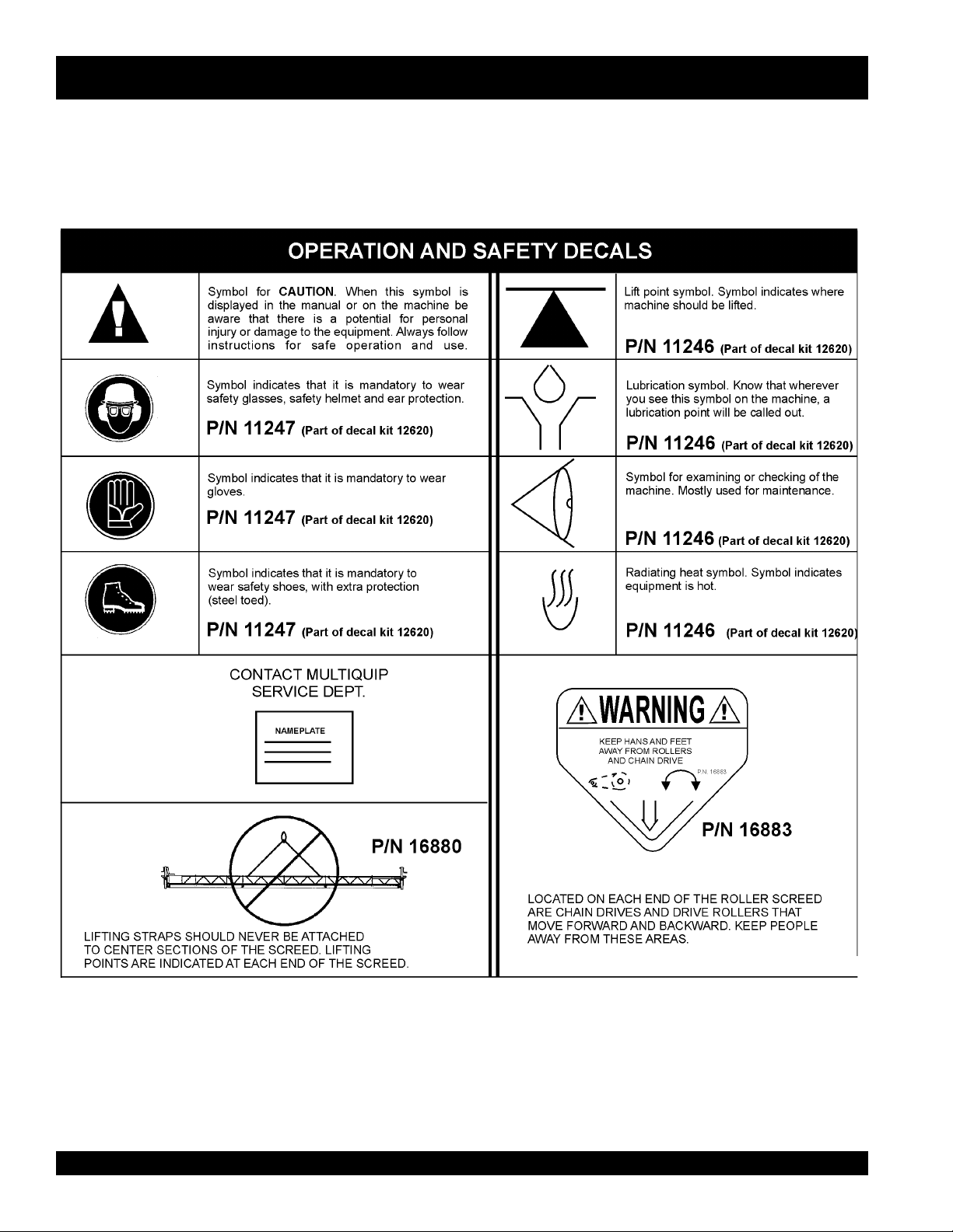
OPERATION AND SAFETY DECALS
Machine Safety Decals
The WRS-5200 Ride-On Roller Screed is equipped with a number of safety decals. These decals are provided for operator safety
and maintenance information. The illustration below and on the next page shows these decals as they appear on the machine.
Should any of these decals become unreadable, replacements can be obtained from your dealer.
PAGE 8 — WRS 5200 RIDE-ON ROLLER SCREED — PARTS MANUAL — REV. #2 (08/09/02)
Page 9
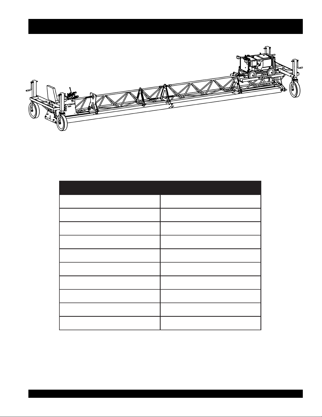
WRS-5200 — SPECIFICATIONS
Figure 1. WRS-5200 Ride-On Roller Screed
)snoitceS9xaM(htgneL)sretem48.51(.TF25
)sdnEtA(htdiW)sretem1.2(.TF7
)htgneL.xaM(thgieW).gk086(SBL005,1
)tinUrewoP(thgieW)gk722(.SBL005
deepSebuTekirtSMPR054xaM
deepSebuTevirDMPR051.xaM
erusserPgnitarepOciluardyHISP0002.xaM
liOciluardyH64OSIVMWA
enignEnanOPH02
leuFenilosaGdedaelnU
SNOITACIFICEPSDEERCSRELLOR.1ELBAT
WRS 5200 RIDE-ON ROLLER SCREED — PARTS MANUAL— REV. 1# (08/09/02) — PAGE 9
Page 10
WMS MULTI-USE SCREED — SAFETY MESSAGE ALERT SYMBOLS
FOR YOUR SAFETY AND THE SAFETY OF OTHERS!
Safety precautions should be followed at all times when
operating this equipment. Failure to read and understand the
Safety Messages and Operating Instructions could result in
injury to yourself and others.
HAZARD SYMBOLS
NOTE
This Owner's Manual has been developed to provide
complete instructions for the safe and efficient operation
of the Multiquip Model WRS-5200 Ride-On Roller
Screed. Refer to the engine manufacturers instructions
for data relative to its safe operation.
Before using this mini-screed, ensure that the
operating individual has read and understands all
instructions in this manual.
SAFETY MESSAGE ALERT SYMBOLS
The three (3) Safety Messages shown below will inform you
about potential hazards that could injure you or others. The
Safety Messages specifically address the level of exposure to
the operator, and are preceded by one of three words: DANGER,
WARNING, or CAUTION.
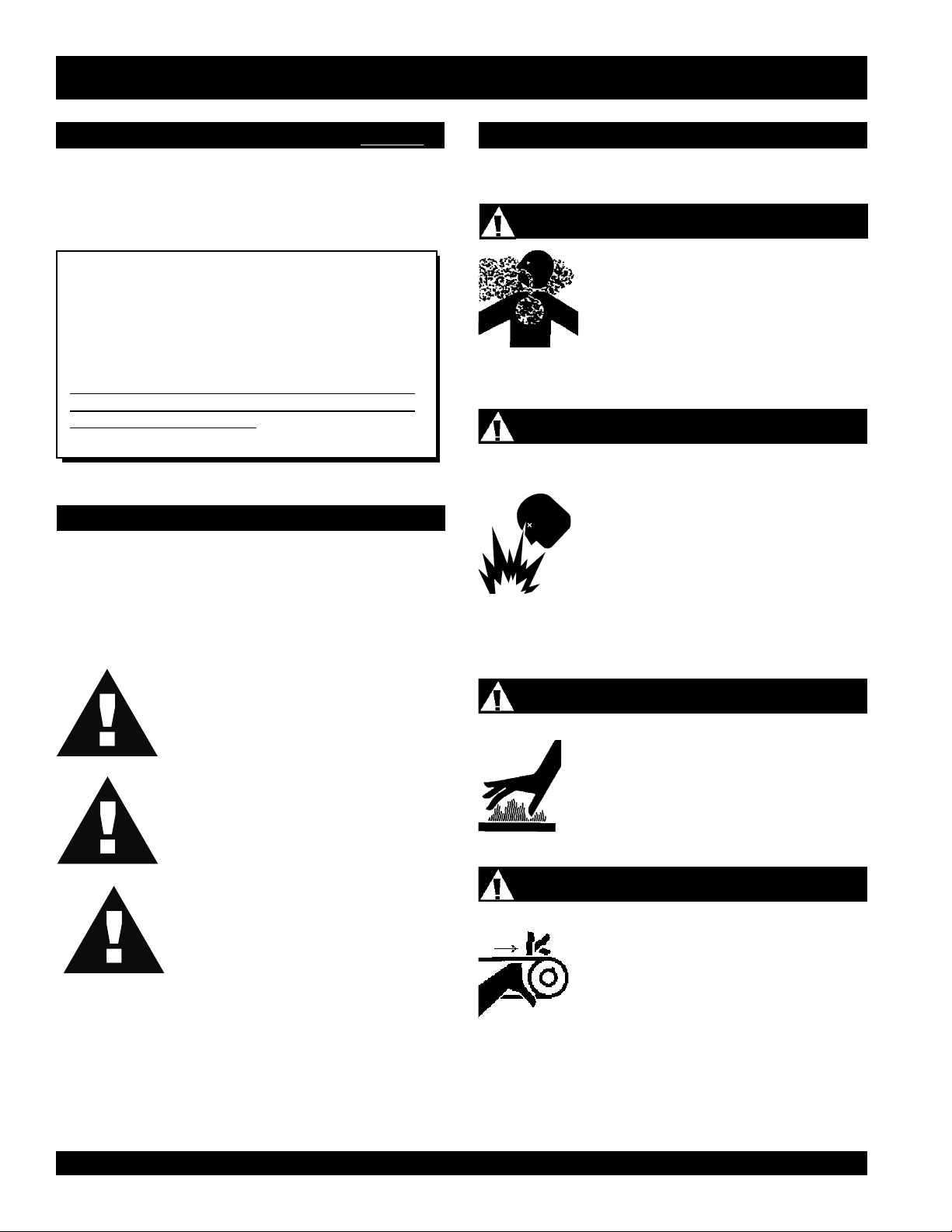
Lethal Exhaust Gases
Engine exhaust gases contain poisonous
carbon monoxide. This gas is colorless and
odorless, and can cause death if inhaled.
NEVER operate this equipment in a confined
area or enclosed structure that does not
provide ample free flow air.
Explosive Fuel
GASOLINE is extremely flammable, and its
vapors can cause an explosion if ignited. DO
NOT start the engine near spilled fuel or
combustible fluids. DO NOT fill the fuel tank
while the engine is running or hot. DO NOT
overfill tank, since spilled fuel could ignite if it
comes into contact with hot engine parts or
sparks from the ignition system. Store fuel in
approved containers, in well-ventilated areas
and away from sparks and flames. NEVER
use fuel as a cleaning agent.
DANGER: You WILL be KILLED or
SERIOUSLY injured if you do not follow
directions.
WARNING: You CAN be KILLED or
SERIOUSLY injured if you do not follow
directions.
CAUTION: You CAN be injured if you
do not follow directions.
Potential hazards associated with WRS-5200 Ride-On Roller
Screed operation will be referenced with Hazard Symbols which
appear throughout this manual, and will be referenced in
conjunction with Safety Message Alert Symbols.
Burn Hazards
Engine components can generate extreme heat.
To prevent burns, DO NOT touch these areas
while the engine is running or immediately after
operations. Never operate the engine with heat
shields or heat guards removed.
Rotating Parts
NEVER operate equipment with covers, or
guards removed. Keep fingers, hands, hair and
clothing away from all moving parts to prevent
injury.
PAGE 10 — WRS 5200 RIDE-ON ROLLER SCREED — PARTS MANUAL — REV. #2 (08/09/02)
Page 11
WMS MULTI-USE SCREED — SAFETY MESSAGE ALERT SYMBOLS
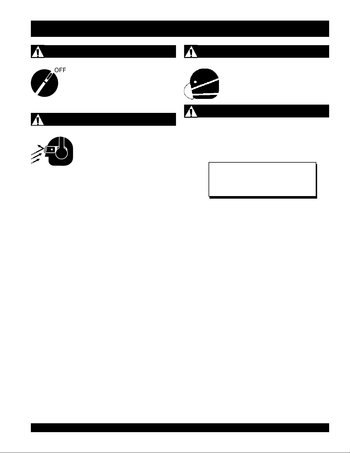
Accidental Starting
ALWAYS place the engine ON/OFF switch in
the OFF position, and remove the ignition key
when the machine is not in use.
Sight and Hearing hazard
ALWAYS wear approved eye and hearing
protection.
Respiratory Hazard
ALWAYS wear approved respiratory
protection.
Equipment Damage Messages
Other important messages are provided throughout this manual
to help prevent damage to your trash pump, other property, or
the surrounding environment.
NOTE
This mini-screed, other property, or the
surrounding environment could be damaged
if you do not follow instructions.
WRS 5200 RIDE-ON ROLLER SCREED — PARTS MANUAL— REV. 1# (08/09/02) — PAGE 11
Page 12
WRS-5200 — RULES FOR SAFE OPERATION
■
CAUTIONCAUTION
CAUTION
CAUTIONCAUTION
The following safety guidelines should always be used when
operating the WRS-5200 Ride-On Roller Screed.
:
Failure to follow instructions in this manual may
lead to serious injury or even death! This
equipment is to be operated by trained and
qualified personnel only! This equipment is for
industrial use only.
GENERAL SAFETY
■
DO NOT operate or service this equipment
before reading this entire manual.
■
This equipment should not be operated by
persons under 18 years of age.
■
NEVER operate this equipment without proper
protective clothing, shatterproof glasses, steeltoed boots and other protective devices required
by the job.
NEVER touch the hot exhaust
manifold, muffler or cylinder. Allow
these parts to cool before servicing
engine or trowel.
■
High Temperatures – Allow the engine to cool before adding
fuel or performing service and maintenance functions. Contact
with
■
The power units's engine requires an adequate free flow of
cooling air. NEVER operate the screed in any enclosed or
hot
components can cause serious burns.
narrow area where free flow of the
air is restricted. If the air flow is
restricted it will cause serious
damage to the machine or engine
and may cause injury to people.
Remember the machine's engine
gives off
monoxide gas.
DEADLY
carbon
■
NEVER operate this equipment when not
feeling well due to fatigue, illness or taking
medicine.
■
NEVER operate this equipment under
the influence or drugs or alcohol.
■
NEVER use accessories or attachments, which are not
recommended by Multiquip for this equipment. Damage to
the equipment and/or injury to user may result.
■
Manufacturer does not assume responsibility for any accident
due to equipment modifications.
■
Whenever necessary, replace nameplate, operation and
safety decals when they become difficult read.
■
ALWAYS check the machine for loosened threads or bolts
before starting.
■
ALWAYS try to do most work during daylight hours or
■
■
■
■
■
with sufficient artificial lighting. Visibility must be good
for this machine to be used effectively and safely.
■
Check the safety kill switch. It is recommended to test
the engine kill switch prior to each use to ensure the
switch is operating properly.
ALWAYS refuel in a well-ventilated area, away from sparks
and open flames.
ALWAYS use extreme caution when
working with flammable liquids. When
refueling, stop the engine and allow it to
cool. DO NOT smoke near the screed. Fire
or explosion could result from fuel vapors,
or if fuel is spilled on a hot engine.
NEVER operate the screed in an explosive atmosphere or
near combustible materials. An explosion or fire could result
causing severe
Topping-off to filler port is dangerous, as it tends to spill fuel.
NEVER store the machine with fuel in the tank for an
bodily harm or even death.
extended period of time. Always clean up spilled fuel
immediately!
PAGE 12 — WRS 5200 RIDE-ON ROLLER SCREED — PARTS MANUAL — REV. #2 (08/09/02)
Page 13

WRS-5200 — RULES FOR SAFE OPERATION
The following safety guidelines should always be used when
operating the WRS-5200 Screed:
GENERAL SAFETY
■
DO NOT operate this equipment unless all guards and safety
devices are attached and in place.
■
Use proper heavy lifting techniques when moving equipment.
This screed is very heavy. It should be lifted only with a lifting
device (i.e. crane, forklift, etc.) with a lifting capacity of at least
one ton.
■
Check to make sure that the operating area is clear before
starting the engine.
■
ALWAYS have throttle at idle position while starting the
engine.
■
ALWAYS keep clear of rotating or moving parts while
operating this equipment.
■
NEVER leave the machine unattended while running.
■
Refuel in a well-ventilated area, away from sparks and open
flames.
■
Moving Parts - Shut down the engine and disconnect battery
before performing service or maintenance functions. Contact
with moving parts can cause serious injury.
■
Unauthorized equipment modifications will void all
warranties.
■
Disconnect battery and spark plug wires before attempting
service.
CAUTIONCAUTION
CAUTION
CAUTIONCAUTION
:
MAINTENANCE SAFETY
■
Disconnect the battery and spark plug wires before attempting
any type of service.
■
Securely support any machine components that must be
raised.
■
NEVER lubricate components or attempt service on a running
machine.
■
Allow the machine a proper amount of time to cool before
servicing.
■
Keep the machinery in proper running condition.
■
Make sure that there is no buildup of concrete, grease, oil or
debris on the machine.
■
Fix damage to the machine immediately and always replace
broken parts.
■
Dispose of hazardous waste properly. Examples of potentially
hazardous waste are used motor oil, fuel and fuel filters.
■
DO NOT use food or plastic containers to dispose of
hazardous waste.
■
DO NOT pour waste, oil or fuel directly onto the ground,
down a drain or into any water source.
Lifting the Screed and Power unit
DANGERDANGER
DANGER
DANGERDANGER
Temperatures
■
High Temperatures – Allow the machine
and engine to cool before adding fuel or
performing service and maintenance functions.
hot
Contact with
serious burns.
components can cause
■
Use straps of adequate lifting capacity to lift the drive roller
and strike tube.
■
To lift the power unit, attach a crane or lifting device of
adequate lifting capacity to the power unit's lifting bail.
:
■
When lifting of the screed or power unit is
required, NEVER stand underneath the
screed or power unit The possibility exist that
severe bodily harm or even death may occur.
CAUTIONCAUTION
CAUTION
CAUTIONCAUTION
:
Emergencies
■
Always know the location of the nearest
extinguisher
location of the nearest telephone. Also know
the phone numbers of the nearest
doctor
will be invaluable in the case of an emergency.
WRS 5200 RIDE-ON ROLLER SCREED — PARTS MANUAL— REV. 1# (08/09/02) — PAGE 13
and
and
fire department
first aid kit
. Know the
ambulance
. This information
fire
,
Page 14

WRS-5200 — FEATURES
A. DESIGN
⇒
Ride-on design for easy maneuverability on the job.
⇒
Designed to meet tight paving specifications.
⇒
Hydraulic power for easy operation.
⇒
20 HP gasoline engine.
⇒
Rubber coated drive tubes controlled independently of
each other for simple alignment corrections.
⇒
Crown and camber adjustments that are easily adjusted.
⇒
Powder coated paint finish for longer life, professional
appearance and easy clean up.
B. FLEXIBILITY
D. PRODUCTIVITY
⇒
Ride-on design for easy maneuverability on the job.
Strikes off over 10,000 square feet per hour.
⇒
Instant forward/reverse screeding action. Strikes off
concrete more quickly than conventional methods.
⇒
Screed bays from 15 to 50 feet wide using a combination of strike tubes. Comes complete with six tubes
(two 18 ft.; two 14 ft.; one 16 ft.; one 8 ft.).
⇒
Ideal for handling low slump
concrete.
C. QUALITY
⇒
Assists in achieving optimum F-numbers using standard finishing techniques.
⇒
Produces a floor with excellent surface aggregate consolidation, resulting in a harder, longer wearing surface
finish.
PAGE 14 — WRS 5200 RIDE-ON ROLLER SCREED — PARTS MANUAL — REV. #2 (08/09/02)
Page 15
WRS-5200 — ASSEMBLY INSTRUCTIONS
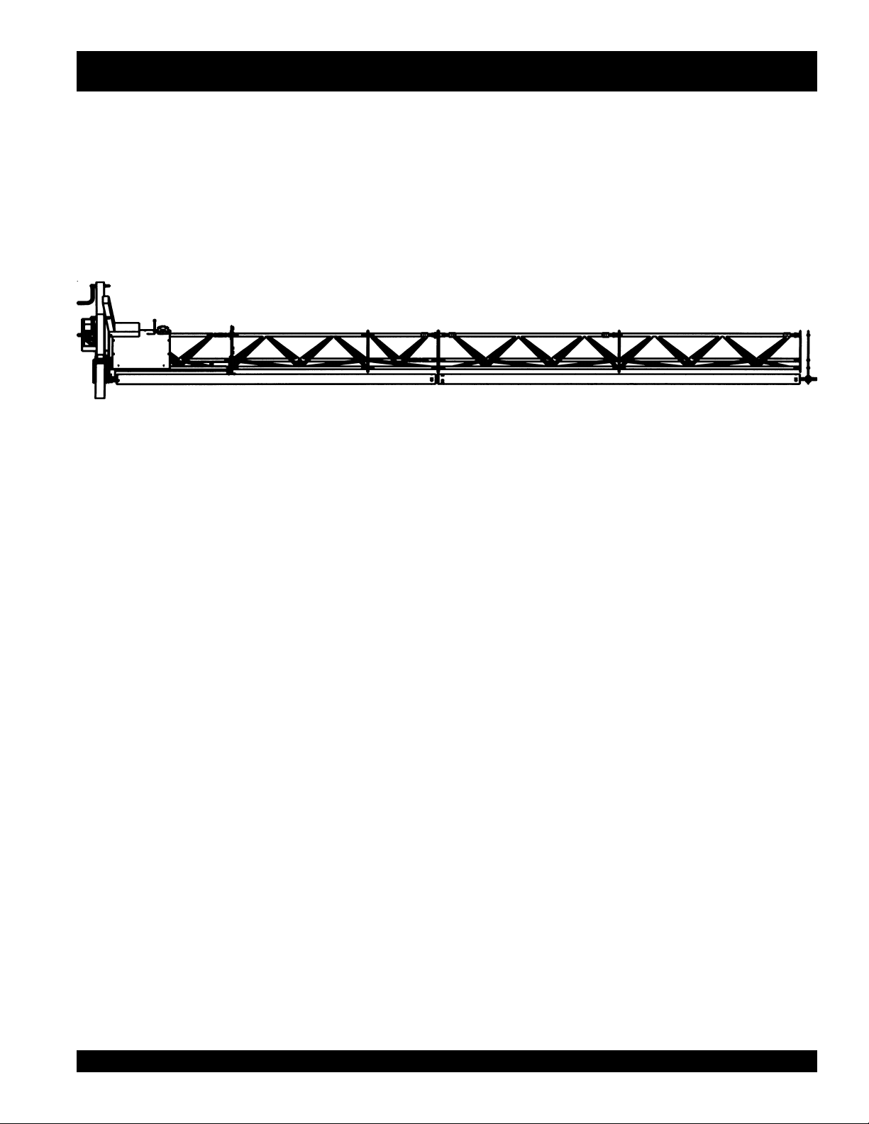
A. ROLLER SCREED PARTS ILLUSTRATION
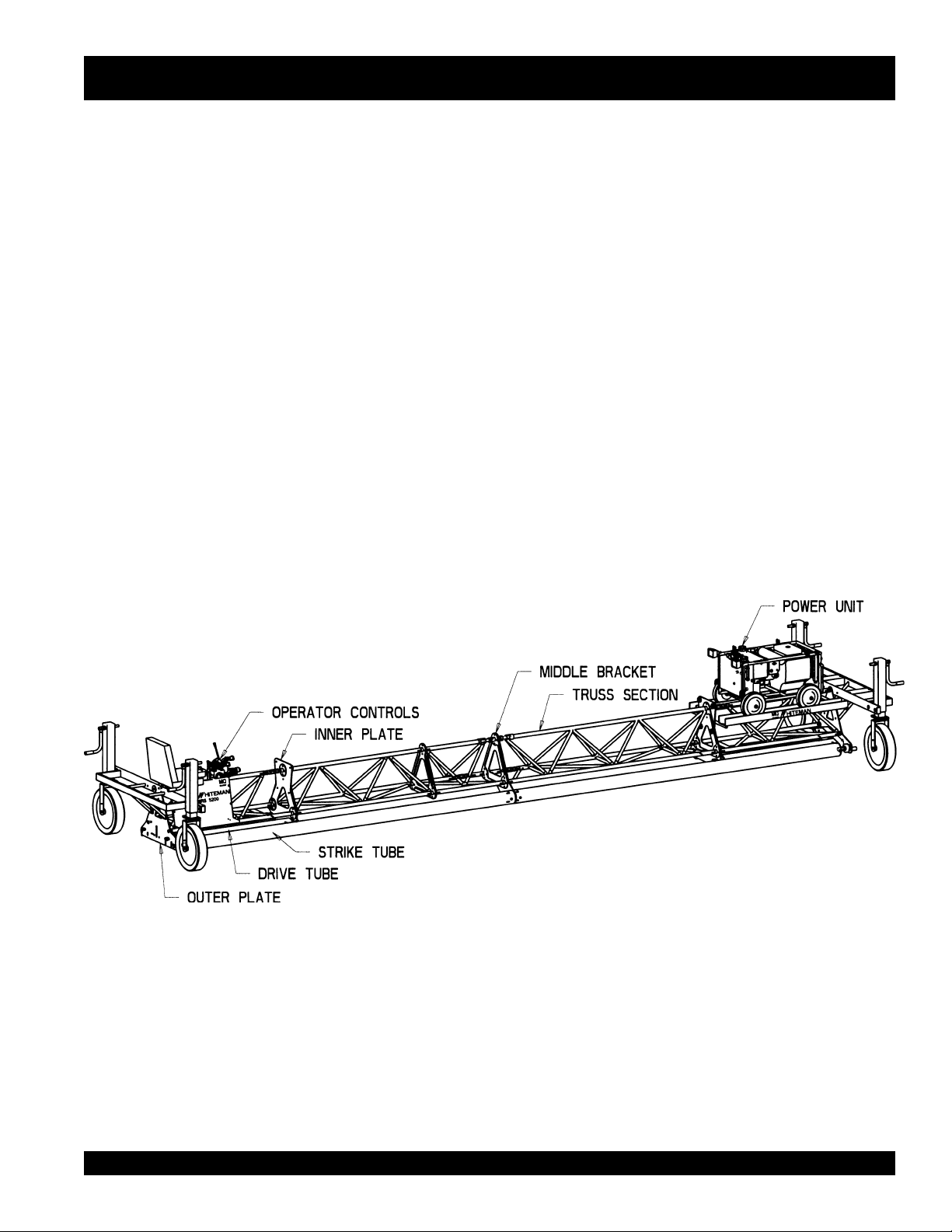
See Figure 2 below for general parts location.
B. PUTTING INTO SERVICE
The purpose of the instructions section of this manual is to
explain the intended setup, use and maintenance procedures
recommended by Whiteman Industries.
Before packaging and shipment, this Whiteman Ride-on Roller
Screed was run and tested at the factory. If there are ANY
problems, please contact the Multiquip Service Department.
Make sure that all manuals and instructions are read carefully before putting your new Whiteman Roller Screed into
service. Improper setup, use or maintenance of this equipment could result in personnel injury or damage to the equipment. Listed in Figure 2, are the location of main parts
described in the next section.
Figure 2. General Parts Location
WRS 5200 RIDE-ON ROLLER SCREED — PARTS MANUAL— REV. 1# (08/09/02) — PAGE 15
Page 16
WRS-5200 — ASSEMBLY INSTRUCTIONS
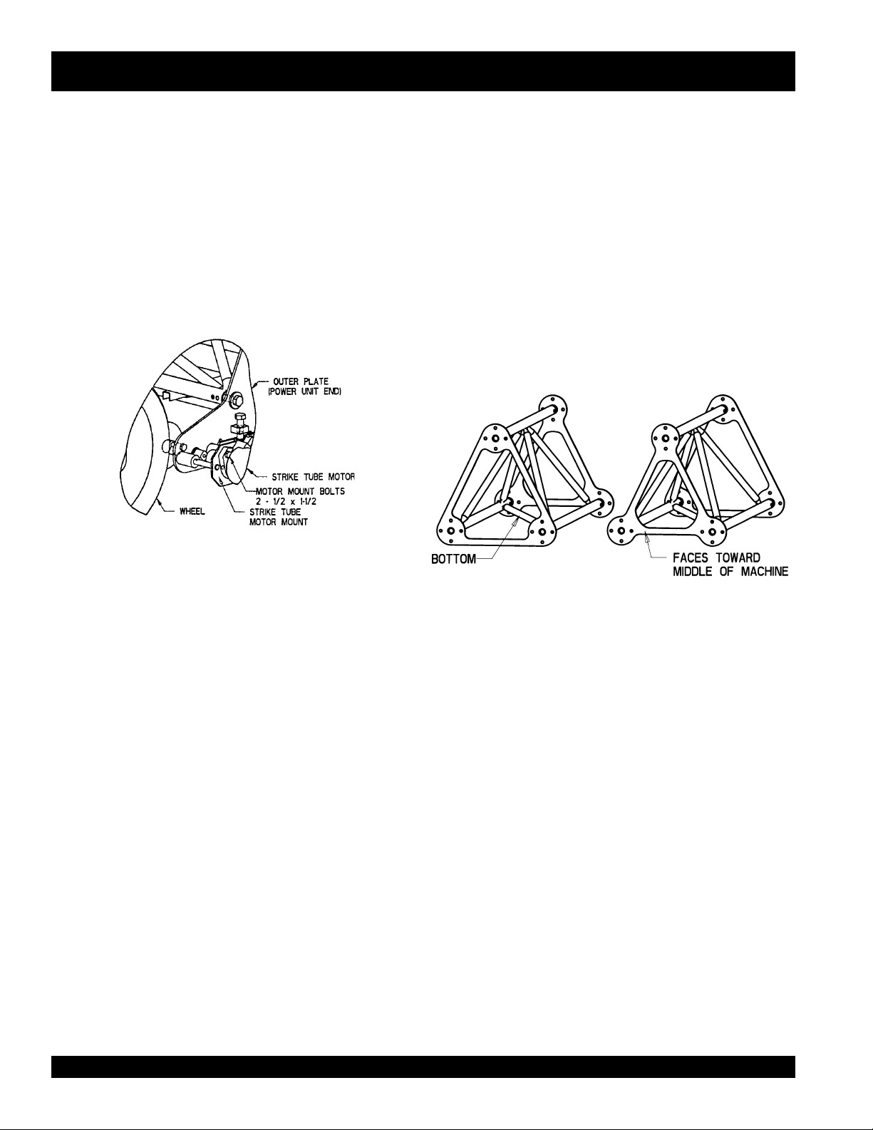
C. POWER UNIT ASSEMBLY
The power unit comes completely assembled. However,
before operating the screed, the hydraulic strike tube motor
from the power unit must be bolted to the motor mount, which
comes with the screed, as shown in Figure 3. This takes
two bolts, ½ X 1-1/2.
IMPORTANT: If you change power units, leave the strike
tube motor mount with the roller screed for the next power
unit
.
Figure 3. Strike Tube Motor Assembly
D. ROLLER SCREED ASSEMBLY
2. Description
The WRS 5200 Ride-On Roller Screed is made up of truss
sections (Figure 4) which vary in length from 3 to 9 feet.
These truss sections support the 6 inch tubing (strike tube)
which runs along the front of the machine. This strike tube
comes in four different lengths, 8, 14, 16 and 18 feet. By
coordinating the truss section and strike tube lengths, various roller screed lengths can be assembled.
Table 2 shows the different combination of truss
sections and strike tube lengths to get the desired
roller screed length. Dimensions are in feet
Figure 4. Truss End Plate
Table 2. ROLLER SCREED ASSEMBLY
LENG.(FT)* TRUSS SECTION (FT)** LETTER CODE ON TRUSS
SECTION STRIKE TUBE(FT)
18 5,8,5 L,RM8,R 18
22 5,9,3,5 L,L14,R8,R 14,8
26 5,4,9,3,5 L,L18,L14,R8,R 18,8
28 5,9,3,6,5 L,L14,R8,R14,R 14,14
30 5,9,8,3,5 L,L14,RM8,R8,R 14,16
32 5,9,3,6,4,5 L,L14,R8,R14,R18,R 14,18
36 5,9,8,3,6,5 L,L14,RM8,R8,R14,R 14,8,14
40 5,9,8,3,6,4,5 L,L14,RM8,R8,R14,R18,R 14,8,18
44 5,9,8,8,3,6,5 L,L14,LM8,RM8,R8,R14,R 14,16,14
44 5,4,9,8,3,6,4,5 L,L18,L14,RM8,R8,R14,R18,R 18,8,18
48 5,9,8,8,3,6,4,5 L,L14,LM8,RM8,R8,R14,R18,R 14,16,18
52 5,4,9,8,8,3,6,4,5 L,L18,L14,LM8,RM8,R8,R14,R18,R 18,16,18
* Actual concrete form width should be at least 2 foot less than screed length.
** Left side of Table I in the truss section represents the power unit end
PAGE 16 — WRS 5200 RIDE-ON ROLLER SCREED — PARTS MANUAL — REV. #2 (08/09/02)
Page 17
WRS-5200 — ASSEMBLY INSTRUCTIONS
It is important in the assembly of the roller screed to keep
truss sections on the appropriate side. To help with this,
each truss section is stamped with a letter and a number.
This stamping is located on the top pipe of each section.
For example, L14, would represent left or the power
unit end and combine this section (9 feet) with the
end section (5 feet), gives you 14 feet. This is the
strike tube length. The stamping on the 9 foot truss
section would be L14. Examples of the assembly for
different screed lengths are shown in Appendix C.
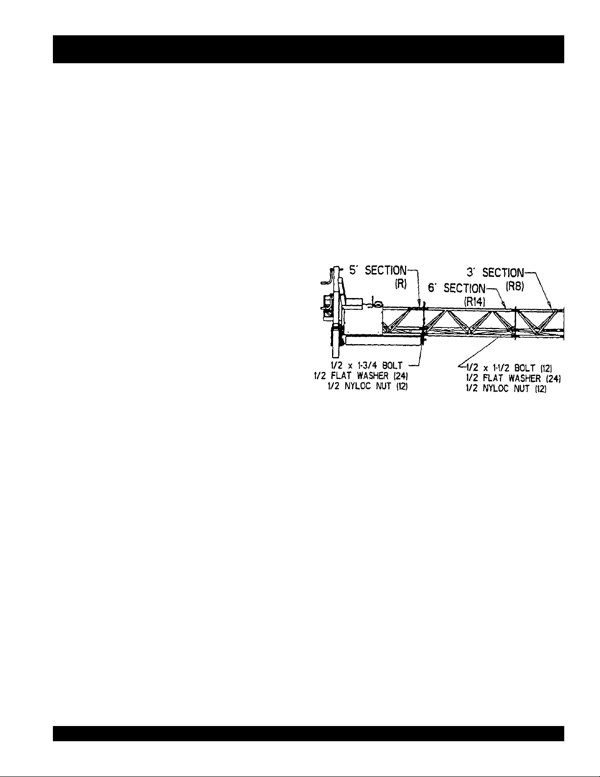
2. Assembly of the Roller Screed
To begin with, bolt together truss sections that match the
length of the strike tubes desired. Find the length of roller
screed wanted in the Appendix C and match the strike tubes
and truss sections. Use 1-1/2” long bolts where 2 joints
come together and 1-3/4” long bolts where 3 joints meet.
Don’t bolt truss sections from other strike tube lengths together yet.
As an example, the assembly of a 44’ roller screed is shown.
First check the Appendix C and find the length of screed
wanted. Lay the parts as shown in the drawing out in the
assembly area. Assemble the truss sections to match the
strike tube lengths. For this screed, the strike tube lengths
are 14’, 16’ and 14’. The following Figures, 4, 5 and 6, are
the truss sections assembled to match the strike tubes.
Task 1.
Assemble right, left and middle truss sections. See Figures
5, 6, and 7.
As an example, the assembly of a 44’ roller screed is shown.
First check the Appendix C and find the length of screed
wanted. Lay the parts as shown in the drawing out in the
assembly area. Assemble the truss sections to match the
strike tube lengths. For this screed, the strike tube lengths
are 14’, 16’ and 14’.
Figure 5. Right Section 14 Feet
WRS 5200 RIDE-ON ROLLER SCREED — PARTS MANUAL— REV. 1# (08/09/02) — PAGE 17
Page 18
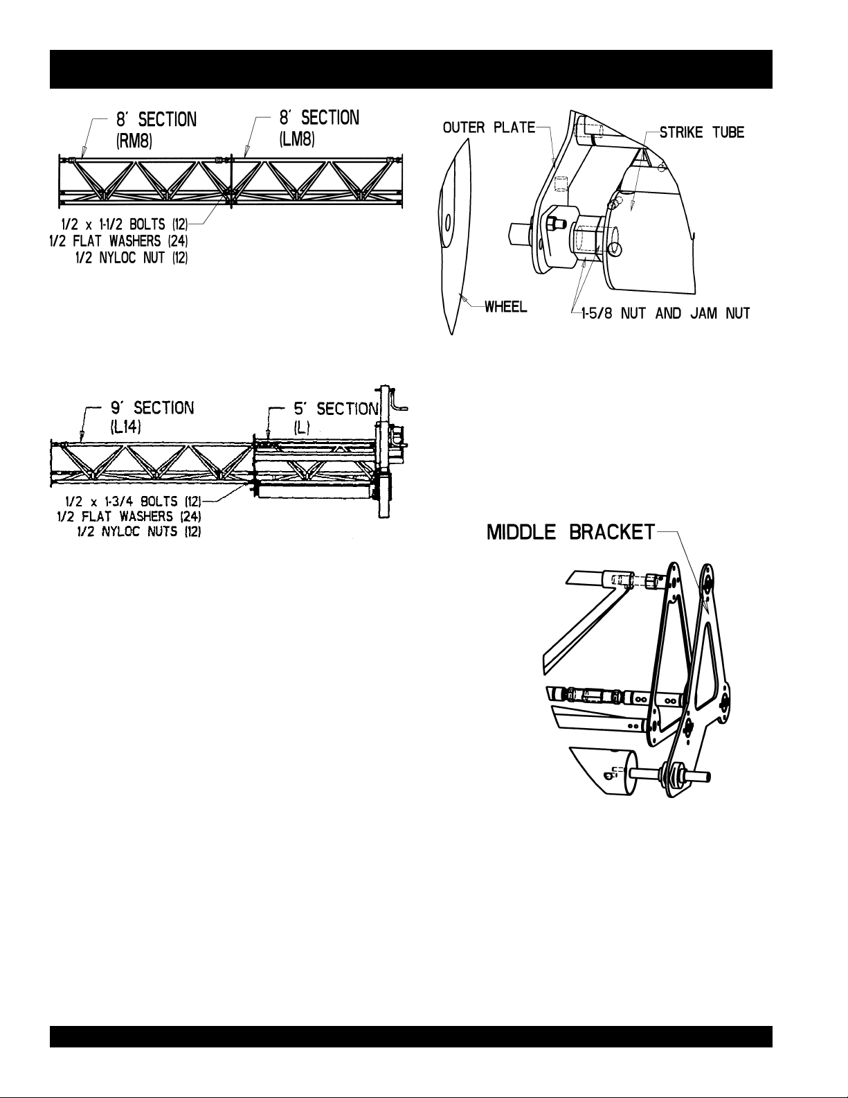
Figure 6. Middle Section 16 Feet
WRS-5200 — ASSEMBLY INSTRUCTIONS
Figure 8. Strike Tube Mount
Task 3.
Take the middle bracket and insert the splined shaft of it into
the other end of the strike tube as shown in Figure 9. Slide
the middle bracket pins into the section just made.
Figure 7. Left Section 14 Feet
Task 2.
Once the assemblies mentioned above are finished, start
on one end, take the strike tube and insert it into the 1-3/8
bearing mounted on the outer plate as shown in Figure 8.
The 1-5/8 nut and jam nut should be turned in until they are
against the strike tube hub.
Figure 9. Middle Bracket Mount
PAGE 18 — WRS 5200 RIDE-ON ROLLER SCREED — PARTS MANUAL — REV. #2 (08/09/02)
Page 19
WRS-5200 — ASSEMBLY INSTRUCTIONS
Task 4.
If another middle bracket is not required, go to the next paragraph. Two middle brackets are required for three strike tubes,
one for two strike tubes. If another middle bracket is required, insert the middle strike tube into the splined shaft of the
middle bracket mentioned above. Assemble the truss sections and middle bracket using the ½ X 1-3/4 bolts. Working your
way across, take the next middle bracket and insert the splined shaft into the middle strike tube as shown in Figure 9 & 10.
Figure 10. Middle Section
Task 5
Now go to the other end of the roller screed, take the strike
tube there and insert it into the second middle bracket’s
splined shaft. As you pull the last 14’ section (Figure 7) into
place, insert the end of the strike tube into the bearing as
you did in Figure 7. Use ½ x 1-3/4 bolts to bolt the two truss
sections and the middle bracket together.
Task 6.
Once the truss sections are together, string the four long
hydraulic hoses through the middle of the trusses. Two male
and two female quick connects are required at the other
end, one male and female of the 5/8” hose and the same for
the ½” hose.
Task 7.
Put the tarps on the appropriate section. The section of the
tarp where two nylon straps are close together should fit
over a truss joint. All tarps were made to full length per
section.
The tarp for the right section (13’11”) will have two places for
the truss joint. It will have a 4 foot section (which for this
set-up will be folded back under the next section of tarp) and
a 6 and 3 foot section
.
The middle tarp (16’) has a place for the truss joint right in
the middle.
The left tarp (13’5”) has one truss joint located 4 foot in from
the end. For this set-up, the 4 foot section will be folded
back under the 9 foot.
The buckles on the tarp should be on the back side (strike
tube is on front side) and the tarp drain hole on the bottom
when finished.
Task 8.
Two more items need to be added on the outside of the
tarps. These are the 50 foot electric cord and the pump
lever cable. Before buckling the tarp, put the cable and cord
behind enough buckles to hold them in place.
Task 9.
Adjust the 1-5/8” nuts on the strike tubes next to the outer
plates so the other end of the strike tube next to the middle
bracket is spaced from 1/16 to 1/8.”
WRS 5200 RIDE-ON ROLLER SCREED — PARTS MANUAL— REV. 1# (08/09/02) — PAGE 19
Page 20
WRS-5200 — ASSEMBLY INSTRUCTIONS
Task 10.
Place the power unit on the appropriate end and the roller
screed is ready to use.
D. HANDLING
1. Moving the Machine
WARNING!
DO NOT ATTEMPT TO LIFT THE SCREED
FROM THE MIDDLE SECTIONS.
Your Whiteman roller screed was designed to be moved
and handled in several ways. Casters that can be lowered
are provided to move the machine on and off forms and for
moving short distances. When using the casters and
moving short distances, the power unit may be left on the
roller screed.
⇒
When lifting the roller screed to load for transporting or
other purposes, the power unit should be taken off.
⇒
Care should be taken to lift the machine correctly. With
a fork lift, one end at a time can be lifted onto the transport. Lifting straps should be placed around the top pipe
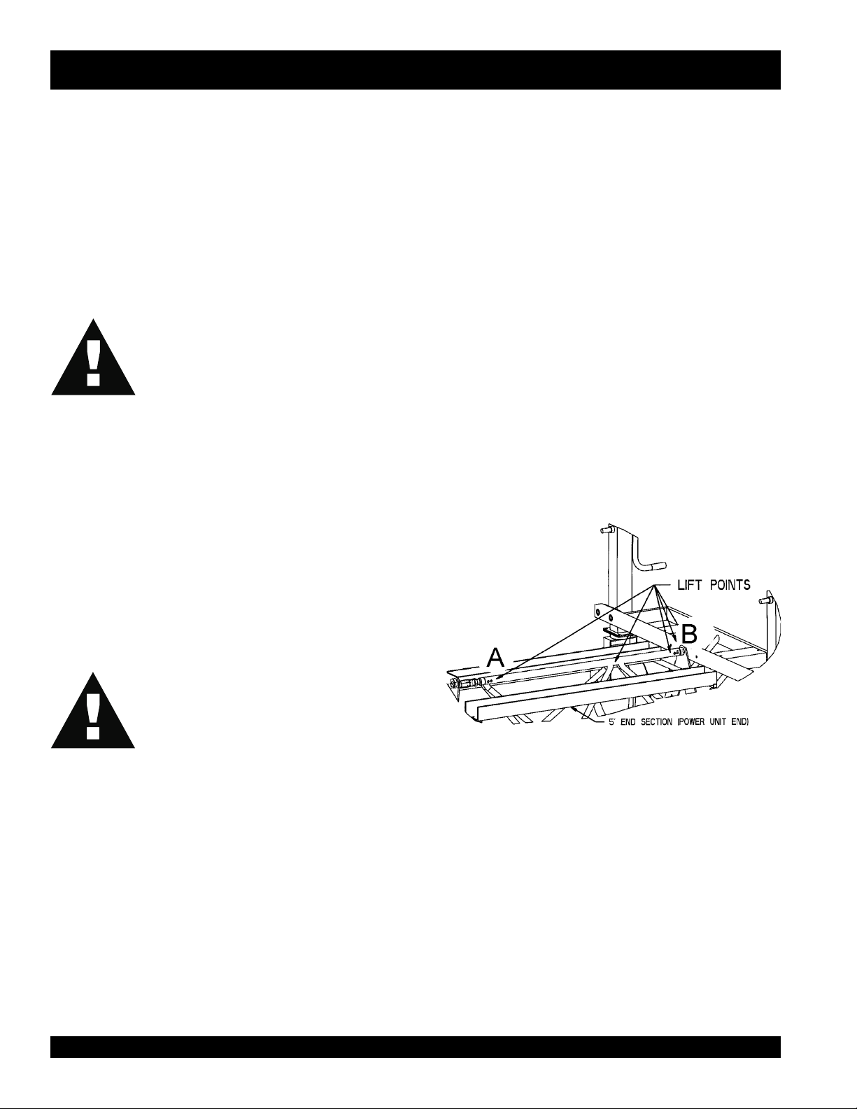
in the 5’ end sections. Figure 10 illustrates the recommended lifting points.
⇒
Care should These lifting positions are the same for both
ends. Attach a lifting strap to one of these points. The
safety snap pins in the top turnbuckles of the truss sections are not designed to carry the weight of the machine during lifting. The top of the truss sections should
always be kept in compression. Lifting with straps or
forks from center sections may damage the machine or
bend these pins. Figure 11 shows lifting points A & B.
Lifting point “B” can be used with any screed length while
lifting point “A” should only be used for screed lengths
longer than 32 feet.
If lifting the roller screed is planned for transporting or other
reasons, some precautions should be followed.
WARNING!
NEVER TRANSPORT SCREED WITH
THE POWER UNIT ON THE MACHINE
.
Figure 11. Lifting Points
PAGE 20 — WRS 5200 RIDE-ON ROLLER SCREED — PARTS MANUAL — REV. #2 (08/09/02)
Page 21

WRS-5200 — ASSEMBLY INSTRUCTIONS
2. Strike Tube Handling
The strike tubes are a critical component of the roller screed.
If the strike tubes are damaged, it is possible they will not
turn true. Care should be taken to store extra tubes on a
fully supported level surface. Never lift the unit from the
strike tubes.
E. Removable Components
The seat section and power unit are removable. Having
these pieces removable means you can easily take most of
the critical components from the machine with you. This
provides a way to better care for your equipment between
jobs.
To remove the seat, undo the cord and cable from the power
unit and the quick connect hydraulic lines from the stack
valve. Windup the cord and cable.
To remove the power unit, attach lifting straps, front-left and
back-right and lift with fork lift.
WRS 5200 RIDE-ON ROLLER SCREED — PARTS MANUAL— REV. 1# (08/09/02) — PAGE 21
Page 22

WRS-5200 — MACHINE CONTROLS
Operators Position)
1. Electric Box (Figure 12).
WARNING!
WARNING!
NEVER DISABLE OR DISCONNECT THE
EMERGENCY KILL SWITCH.
Your Whiteman Ride-On Roller Screed is equipped with a
safety emergency kill switch. Note: It is provided for operator safety and injury may result if it is disabled, disconnected
or improperly maintained.
Below the kill switch is the “High/Low” toggle switch. This
throttle switch has only two positions.
The choke button is to the right of the Hi/Low switch. To
activate this switch, you must hold it down.
2. Light Switch.
The light switch is located on the fuse box which is mounted
on the radiator end of the power unit.
3. Drive Tube Speed Control Lever (Figure 13).
Located on the far left, above the electric box, this long
handle controls the variable speed of the drive tubes. This
lever should be in the “Straight Up” position when starting
the engine.
THE THROTTLE CONTROL CANNOT BE USED TO STOP THE EN-
GINE.
4. Drive Tube Direction Control Levers (Figure 13).
Figure 12. Electric Box
The key switch, shown in Figure 12, is located to the right of
the kill switch. The key switch should not work if the kill
switch is in the down “Down” position.
THE THROTTLE CONTROL CANNOT BE
USED TO STOP THE ENGINE.
Located in the center, these two levers control the direction
of travel for the drive tubes. They are independent of each
other, so one end can travel forward while the other travels
back. Using the levers in this way lets you steer the roller
screed.
Figure 13. Operator Controls
PAGE 22 — WRS 5200 RIDE-ON ROLLER SCREED — PARTS MANUAL — REV. #2 (08/09/02)
Page 23

WRS-5200 — MACHINE CONTROLS
In order for the drive tubes to move the screed, the “Screed
Operation” valve lever on the power unit must be engaged.
5. Strike Tube Control Lever (Figure 13)
On the far right is the strike tube cable control. Pushing the
lever to the center is the “Neutral Position”. Shifting the
lever either direction determines which way the strike tube
turns. The farther you push/pull the lever, the faster the
strike tubes turn.
6. Form Specifications
Refer to Appendix B for more information on the recommended
type of concrete form to be used.
WRS 5200 RIDE-ON ROLLER SCREED — PARTS MANUAL— REV. 1# (08/09/02) — PAGE 23
Page 24

WRS-5200 — MACHINE START-UP AND OPERATION
A. START-UP
The following steps are intended as a basic guide to machine start-up and operation. Following these procedures
will help preserve and maintain the life of this equipment.
⇒
Check oil levels in engine and hydraulic reservoir.
⇒
Check to make sure there is a full tank of fuel before
starting.
⇒
On the power unit, put the screed operation valve lever
in the “Screed Operation” position.
⇒
Put the two drive tube direction control levers shown in
Figure 12 in the “Middle” position.
⇒
Adjust the drive tube speed control lever shown in Figure 12 to the “Straight Up” position.
⇒
Put throttle switch in “Low,” the “Kill Switch” in the “Up”
position, and depress the “Choke Switch”, if necessary,
while turning the key.
⇒
While sitting in the seat, turn the key and start the engine.
B. CLEANUP
Never allow any concrete to harden on the roller screed.
Immediately after use, wash any concrete off the screed.
Be careful not to spray water on the engine while it is still
hot.
To operate the pressure washer, attach a garden hose to the
pump and turn on the water. Next plug in the quick connect
hoses from the pressure washer to the power unit, adjust
the three way valve on the power unit as indicated by the
decal to the “Pressure Washer” position.
“Clean out” plates for the ends of the center strike tubes
(8’and 16’ tubes) should be removed and the ends cleaned
after each use.
Back off the 1-5/8 nut and jam nut on the outside strike
tubes next to the outer plate. Slide the strike tube away
from the middle bracket and clean the ends.
The solid scraper bars that prevent build-up on the drive
tubes should be removed and cleaned as well as the strike
tube wipers mounted in front of the 5 foot sections.
⇒
Once the engine is warm, put the toggle switch on throttle
control to the “High” position to begin operation.
PAGE 24 — WRS 5200 RIDE-ON ROLLER SCREED — PARTS MANUAL — REV. #2 (08/09/02)
Page 25

WRS-5200 — MACHINE START-UP AND OPERATION
WARNING!
PETROLEUM PRODUCTS ARE FLAMMABLE.
⇒
Lubricate all grease zerks after cleaning the machine
while the chain guards are off, including bearings on the
middle brackets which hold the splined shafts.
Never fill the gas tank while the engine is running or hot.
Petroleum products can cause damage to the environment
so spills should be cleaned up immediately.
C. MAINTENANCE
Note: See the engine manual supplied with your machine
for appropriate engine maintenance schedules and troubleshooting guide for problems.
There is a “Daily Preparation Checklist” in the front section
of this manual. Please feel free to make copies of it and use
it on a daily basis.
Weekly (30-40 Hours)
⇒
Check and clean or replace the engine air filter as necessary.
⇒
Replace the engine oil and filter as necessary, see engine manual.
⇒
Check bolts for tightness on truss sections.
Monthly (100-125 Hours)
⇒
Check air pressure in tires.
Yearly (500-600 Hours)
WARNING!
⇒
Replace hydraulic fluid and filters.
DISCONNECT BATTERY CABLES AND
SPARK PLUG WIRES BEFORE ATTEMPTING ANY SERVICE OR MAINTENANCE ON
THIS MACHINE.
⇒
Check set screws on the middle bracket bearings which
hold the splined shaft in place. If loose, add some liquid
locking agent to the set screws and re-tighten. A “stop”
inside the strike tube prevents the splined shafts from
ever moving too far.
D. MAINTENANCE SCHEDULE
Daily (8-10 Hours)
⇒
Check the fluid levels in the engine and hydraulic reserve , fill as necessary.
WRS 5200 RIDE-ON ROLLER SCREED — PARTS MANUAL— REV. 1# (08/09/02) — PAGE 25
⇒
Note: After the first 100 hours, replace the hydraulic
filter cartridges.
Page 26

WRS-5200 — MAINTENANCE AND ADJUSTMENT PROCEDURES
WARNING!
DO NOT AT ANY TIME MAKE ADJUSTMENTS TO THE ROLLER SCREED WITHOUT STOPPING THE ENGINE AND DISCONNECTING THE SPARK PLUG WIRE.
A. ADJUSTING STRIKE TUBE HEIGHT
Strike tube height is adjusted by raising or lowering the height
of the drive tubes. Figure 14 illustrates this. The chain idler
will also need adjusting in the same direction of travel as the
drive tubes. Loosen the two bolts which hold each drive
tube bearing and adjust the ¾” bolt to desired height. Tighten
the bearing bolts and chain idle adjustment when finished.
Adjust the strike tube so it is just clearing the concrete form.
B. CROWN ADJUSTMENT
To adjust the crown, pull the 3/8” safety snap pin and adjust
the screw with the wrench provided. Shown in Figure 15.
Figure 14. Strike Tube Adjustment
Figure 15. Crown and Camber Adjustment
C. CAMBER ADJUSTMENT
To modify the camber in the screed, adjust the turnbuckle
which is shown in Figure 15. Loosen the two jam nuts and
adjust the screw with the wrenches provided. A plum line
stretched along the front of the machine will help to adjust
straightness to.
PAGE 26 — WRS 5200 RIDE-ON ROLLER SCREED — PARTS MANUAL — REV. #2 (08/09/02)
Page 27

WRS-5200 — MAINTENANCE AND ADJUSTMENT PROCEDURES
D. STRAIGHTNESS OF STRIKE TUBES
Should strike tubes begin turning unevenly, contact your local Multiquip representative for information on strike tube
straightening procedures.
To determine if a strike tube is turning uneven, place a 2 x 4
stud on the ground in the center of the strike tube as it sits
on the machine. Slide it close to the strike tube. Take the
strike tube motor off the end. Spin the strike tube by hand. If
a gap of over 1/8 inch shows up, contact your representative.
E. AUXILIARY HUB
An auxiliary hub, shown in Figure 16, for use with different
strike tubes is provided. Using the hub provides additional
combinations of roller screed lengths. Two ½ x 2-1/4 bolts
are provided for the purpose of bolting the hub to the strike
tube end.
Wiper bars should be adjusted to approximately 1/8” distance from the strike tube. The turnbuckle in the top pipe of
the 5’ section is also an adjustment for the wiper bar. This
adjustment can be used when the end of the wiper bar is too
close to the strike tube. IMPORTANT: Never let anything
rub grooves into the strike tube( i.e. wiper bars, concrete
forms, bolts, etc.) because those grooves in the strike tube
will be transferred into the concrete.
H. STRIKE TUBE ADJUSTMENT NUT
The strike tube adjustment nut, shown in Figure 8, should
be adjusted so the inner edge of the strike tube next to the
middle bracket is spaced at about 1/16 to 1/8”. Note: The
strike tube will bottom out on the splined shaft when 1/16” is
left and further adjustment will bend the outer plate.
I. SPLINED SHAFT SET SCREWS
Each roller screed comes with two middle brackets as shown
in Figure 9. Bearings mounted on the middle bracket hold
the splined shaft. The set screws in the bearings should be
checked for tightness occasionally.
J. REVERSING END CASTER BRACKETS
Figure 17 illustrates how end caster brackets can be reversed. This allows the roller screed to fit into areas close to
walls and columns.
Figure 16. Auxiliary Hub
F. CHANGING THE HYDRAULIC FILTER
Usually the hydraulic filter and oil will be changed at the
same time. If not, creating a back suction on the hydraulic
tank will stop the flow of hydraulic oil when changing the
filters.
G. SCRAPER AND WIPER BAR ADJUSTMENT
Scraper bars should be adjusted to approximately 1/8” distance from the drive tubes.
Figure 17. Reversing Caster Brackets
WRS 5200 RIDE-ON ROLLER SCREED — PARTS MANUAL— REV. 1# (08/09/02) — PAGE 27
Page 28

WRS-5200 — SUGGESTED TRAINING
WARNING!
READ THE INSTRUCTION MANUAL COMPLETELY BEFORE ATTEMPTING MACHINE OPERATION!
The following steps are intended as a basic guide to help in the operation of this
equipment.
A. FAMILIARIZATION WITH EQUIPMENT
Take a walk around the machine. Take notice of all the major
components on the machine like the control handles, the
engine, the strike tubes and the truss sections. Look at the
machine construction. Check the fuel and hydraulic system. Look at the engine and find the oil dipstick. Check the
oil levels in the engine and hydraulic tank. Make sure the
machine has fuel enough for the planned operation.
While seated in the operator’s position, note the locations of
the controls. On the left is the electric box with four switches
which were described in the startup section of this manual.
Just above the electric box on the left is the speed control
lever for the drive tubes.
In the center are the levers of the stack valve which operate
the drive tubes forward and reverse on both ends and finally
on the right side is the lever for running the strike tubes. The
speed of the strike tubes depends on the how far you push/
pull the lever. The cable from this lever is attached to the
hydraulic pump lever on the power unit.
B. FIRST MACHINE OPERATION
Now, following the startup procedure found in the “Machine
Start-up and Operation” section of this manual, start the
engine and let it warm up. Remember that when warming up
an engine, let the engine idle. When the engine is warm, test
the kill switch. The engine should die and the key should not
crank the engine with the emergency kill switch down.
Restart the engine. Before operating the roller screed, check
for people around the machine. As a suggestion, imagine a
rectangle that envelopes the entire machine. Never let anyone into that rectangle while you are operating the machine.
Always be aware of your surroundings.
Practice running the roller screed in a straight line. As you
become comfortable maneuvering the roller screed, try turning off one side of the drive tubes and then the other. This
adjusts how parallel the screed moves with the forms, and
also allows you to steer around the columns.
C. CONCEPTS FOR USE OF ROLLER SCREED
The purpose of the roller screed is to strike off the surface of
the concrete at a predetermined grade. The quality of
screeding has a big effect on floor levelness and flatness.
This machine was designed to be able to go back and forth
on the forms, working the concrete to the desired grade.
The strike tube rotation should always push the concrete
forward into the areas that don’t have concrete yet.
Depending on the slump of the concrete, several passes
might be required for the right strike off grade. On the last
pass over the concrete, rotate the strike tube in the opposite
direction and go slowly forward. This leaves a thin layer
which can be easily bull floated.
PAGE 28 — WRS 5200 RIDE-ON ROLLER SCREED — PARTS MANUAL — REV. #2 (08/09/02)
Page 29

WRS-5200 — SUGGESTED TRAINING
A pressure washer is available as an option with this machine. Figure 18 shows the components that come with this option.
This is a hydraulic-motor driven pump pressure washer which is connected to the power unit with quick connect fittings.
The pressure washer runs at 1500 psi and comes complete with a 50 foot pressure wash hose, trigger gun with insulated
wand and a turbo nozzle.
Figure 18. Pressure Washer
WRS 5200 RIDE-ON ROLLER SCREED — PARTS MANUAL— REV. 1# (08/09/02) — PAGE 29
Page 30

WRS-5200 — FORM SPECIFICATIONS
The Whiteman WRS-5200 roller screed provides all of the
benefits of labor savings, high productivity and enhanced
floor flatness/levelness qualities. To order to maximize these
benefits, care must be taken to insure a successful application. :Inadequate substrate and form support can lead to
form failure causing unnecessary job delays, and expenses
while contributing to poor floor flatness and floor levelness
ratings. The intent of these specifications is to establish
minimum guidelines to help the contractor choose the most
economical and effective form work/support system to fit
any job site needs.
It is recommended that at least the day prior to the concrete
pour, a dry run be accomplished to test the load capacity of
the forms and substrate. Proper job planning is essential to
a successful application.
The WRS-5200 weighs approximately 4000 .lbs (at 52 feet
of screed) approx. 2000 lbs. per side. Any screed support
(forms, rails, rail supports and substrate) must withstan0a
2s0s.0 lb. “point load” at a 2:1 safety factor.
WOOD FORMS-
Wood forms are NOT
Because of the concentrated bearing loads by the screed,
wood is not a good support material. Nominal 2x (1-1/2’7
No.2 Douglas fir is calculated to support a maximum of 1000
lb. The grain could crush and splinter causing level variations and potential failure. 4x (3-1/2") lumber for edge form
should be acceptable.
SCREED RAILS AND SUPPORT-
Screed rails (Figure 19) and supports, independent of slab
edge forming are a preferred method. Due to strength, deflection and traction considerations, 2.5" x 2.5" x 875 (3/16")
wall structural steel tubing with adjustable supports spaced
as shown in the attached drawings. Standard deflection with
a 3/16" wall thickness for the above configuration is 1/6" in 4
ft. Refer to standard material charts for other configurations.
STEEL FORMS-
a
preferred method of screed support.
SUBGRADE/DECK FORMS-
Subgrade must be sound enough to support slab edge forms
and bracing as well as the load imposed by the screed and
its supports. Potential deflection, as in the case with metal
and plywood decks, should be considered when determining
brace and support spacing. Soil subgrades must be well
compacted and must be able to support bearing pressures
greater, than or equal to those imposed by the screed supports and the slab forming. For proper bearing support, shims
should be used to adequately distribute loads where grade
is not level or is soft. Use standard AC:[ concrete form pressures when calculating lateral loads on slab edge forms
Paving forms with 90° lip-edge at bottom with stake pockets
is preferred. If soft or unleveled subgrade is encountered, a
2x bearing pad and/or shims should be used under the steel
forms for additional bearing support. Depending on slab thickness and subgrade, forms may require diagonal bracing.
These specifications are provided as a service to illustrate
the application of MQ - WHITEMAN products only and are
not intended to be fully directive or cover all engineering
details, MQ - WHITEMAN will not be responsible for the
improper application of its products.
PAGE 30 — WRS 5200 RIDE-ON ROLLER SCREED — PARTS MANUAL — REV. #2 (08/09/02)
Page 31

WRS-5200 — SCREED RAILS
Figure 19. Screed Rails
WRS 5200 RIDE-ON ROLLER SCREED — PARTS MANUAL— REV. 1# (08/09/02) — PAGE 31
Page 32

WRS-5200 — 18 AND 22 FOOT SCREED LENGTHS
PAGE 32 — WRS 5200 RIDE-ON ROLLER SCREED — PARTS MANUAL — REV. #2 (08/09/02)
Page 33

WRS-5200 — 26 AND 28 FOOT SCREED LENGTHS
WRS 5200 RIDE-ON ROLLER SCREED — PARTS MANUAL— REV. 1# (08/09/02) — PAGE 33
Page 34

WRS-5200 — 30 AND 32 FOOT SCREED LENGTHS
PAGE 34 — WRS 5200 RIDE-ON ROLLER SCREED — PARTS MANUAL — REV. #2 (08/09/02)
Page 35

WRS-5200 — 36 AND 40 FOOT SCREED LENGTHS
WRS 5200 RIDE-ON ROLLER SCREED — PARTS MANUAL— REV. 1# (08/09/02) — PAGE 35
Page 36

WRS-5200 — 44 FOOT SCREED LENGTHS
PAGE 36 — WRS 5200 RIDE-ON ROLLER SCREED — PARTS MANUAL — REV. #2 (08/09/02)
Page 37

WRS-5200 — 48 AND 52 FOOT SCREED LENGTHS
WRS 5200 RIDE-ON ROLLER SCREED — PARTS MANUAL— REV. 1# (08/09/02) — PAGE 37
Page 38

WRS-5200 — FRAME ASSEMBLY (OPERATOR END)
FRAME ASSEMBLY (OPERATOR END)
PAGE 38 — WRS 5200 RIDE-ON ROLLER SCREED — PARTS MANUAL — REV. #2 (08/09/02)
Page 39

WRS-5200 — FRAME ASSEMBLY (OPERATOR END)
FRAME ASSEMBLY (OPERATOR END)
NO PART NO PART NAME QTY. REMARKS
1 0166 Screw, HHC 3/8-16 x 7/8 1
2 0300 B Washer, Flat, 7/16 SAE 10
3 0448 Washer, Flat, 7/16 SAE 1
4 10133 Nut, Nyloc 3/8-16 6
5 10176 Nut, Nyloc 1/2-13 6
6 1284 Screw, HHC 3/8-16 x 1-1/2 4
7 16223 Bearing, 1-3/8 3
8 16225 Sprocket 2
9 16226 Sprocket, Idler 1
10 16227 Chain, Roller 1
11 16231 Caster, (includes wheels and bracket) 2
12 16303 Mount, Idler Sprocket 1
13 16372 Spacer, 1/4 I
14 16378 Pull Handle W/A 1
15 16469 Bracket, Caster W/A OPER End 1
16 16492 Tube, Drive Rear W/A 1
17 16493 Tube, Drive Front W/A 1
18 16521 Screw, HHCS 1/2-13 x 4 GD 8 4
19 16524 Screw, HHCS 1/2-13 x 1-1/4 GD 8 12
20 16525 Screw, HHCS 1/2-13 x 1-1/2 GD 8 3
21 16529 Screw, HHCS 3/4-10 x 2 GD 8 3
22 16530 Screw, HHC 7/16-14 x 1 1
23 16533 Key, 5/16 x 5/16 x 7/8 2
24 16538 Bearing Adjustment W/A Short 2
25 16539 Bearing Adjustment W/A Long 1
26 16627 Bolt, Shoulder 5/8 x 3/4 PLTD 4
27 16628 Bolt, Shoulder 3/4 x 2-1/4 PLT 4
28 16629 Nut, Nyloc 1/2-13 GD 8 18
29 16658 Wiper, Solid W/A 2
30 16659 Mount, Solid Wiper W/A 3
31 16681 Mount, Wiper Right 1
32 16683 Jack, Screed W/A 2
33 16685 Handle, Jack W/A 2
34 16689 Name Plate, Screed 1
35 16695 Arm, Wiper W/A 2
36 16703 Guard, Chain W/A Control End 1
37 16781 Screw, HHCS 1/2 - 13 x 2. 1/4 GD 8 8
38 16868 Bar, Scraper W/A 2
39 16880 Decal, Lifting Warning 1
40 16883 Decal, Chain Drive Warning 1
41 16890 Screw, HHC 3/4 x 2-1/2 GD 5 1
42 16927 Chain, Roller Offset 1
43 4014 Screw, 2-3/16 P-K Type U Drive 2
44 5054 A Washer, Lock, 1/2 Medium 1
45. 5283 Nut, Nyloc 5/16-18 10
46 9154 Screw, HHC 3/8-16 x 1-3/4 2
47 9503 Nut, Nyloc 5/8-11 4
WRS 5200 RIDE-ON ROLLER SCREED — PARTS MANUAL— REV. 1# (08/09/02) — PAGE 39
Page 40

FRAME ASSEMBLY (ENGINE END)
WRS-5200 — FRAME ASSEMBLY (ENGINE END )
PAGE 40 — WRS 5200 RIDE-ON ROLLER SCREED — PARTS MANUAL — REV. #2 (08/09/02)
Page 41

WRS-5200 — FRAME ASSEMBLY (ENGINE END )
FRAME ASSEMBLY (ENGINE END)
NO PART NO PART NAME QTY. REMARKS
1 0166 Screw, HHC 3/8 - 16 x 7/8 1
2 0189 Grip, Handle 2
3 0300 B Washer, Flat, 5/16 SAE 10
4 0448 Washer, Flat, 7/16 SAE 1
5 10133 Nut, Nyloc 3/8 -16 14
6 10176 Nut, Nyloc 1/2 -13 6
7 1284 Screw, HHC 3/8 -16 x 1-1/2 4
8 16223 Bearing, 1-3/8 3
9 16225 Sprocket 2
10 16226 Sprocket, Idler 1
11 16227 Chain, Roller 1
12 16231 Caster, (includes wheels & bracket) 2
13 16270 Scraper Bar W/A 1
14 16273 Chain Guard W/A 1
15 16303 Mount, Idler Sprocket 1
16 16372 Spacer, 1/4 1
17 16378 Pull Handle W/A I
18 16442 Mount, Power, Unit Short 2
19 16446 Mount, Power, Unit Long 2
20 16492 Tube, Drive Rear W/A 1
21 16493 Tube, Drive Front W/A I
22 16521 Screw, HHCS 1/2 -13 x 4 GD 8 4
23 16524 Screw, HHC 1/2-13 x 1. IA GD 8 12
24 16525 Screw, HHC 1/2 -13 x 1. I/2 GD 8 3
25 16529 Screw, HHC 3/4 -10 x 2 GD 8 3
WRS 5200 RIDE-ON ROLLER SCREED — PARTS MANUAL— REV. 1# (08/09/02) — PAGE 41
Page 42

WRS-5200 — FRAME ASSEMBLY ENGINE END (CONT).
FRAME ASSEMBLY ENGINE END (CONT.)
PAGE 42 — WRS 5200 RIDE-ON ROLLER SCREED — PARTS MANUAL — REV. #2 (08/09/02)
Page 43

WRS-5200 — FRAME ASSEMBLY ENGINE END (CONT).
FRAME ASSEMBLY ENGINE END (CONT.)
NO PART NO PART NAME QTY. REMARKS
26 16530 Screw, HHC 7/16 -14 x 1 1
27 16533 Key, 5/16 x 5/16 x 7/8 2
28 16538 Bearing Adjustment W/A Short 2
29 16539 Bearing Adjustment W/A Long 1
30 16563 Decal MQ Multiquip Whiteman 2
31 16627 Bolt, Shoulder 5/8 x ~A PLTD 4
32 16628 Bolt, Shoulder 3/4 x - 2 1/4 PLT 4
33 16629 Nut, Nyloc 1/2-13 GD 8 18
34 16632 Bracket, Caster W/A (power unit end) 1
35 16658 Wiper, Solid W/A 2
36 16659 Mount, Solid Wiper W/A 3
37 16683 Jack, Screed W/A 2
38 16685 Handle, Jack W/A 2
39 16693 Bolt, Carriage 3/8-16 x 2 4
40 16695 Arm, Wiper W/A 2
41 16751 Arm, Power Unit Outer Plate 1
42 16781 Screw, HHCS 1/2-13 x 2.1/4 GD 8 8
43 16868 Bar, Scraper W/A 2
44 16880 Decal, Lifting Warning 1
45 16883 Decal, Chain Drive Warning 1
46 16890 Screw, HHC 3/4 x 2-1/2 GD5 1
47 16927 Chain, roller Offset 1
48 5054 A Washer, Lock, 1/2 Medium 1
49 5283 Nut, Nyloc 5/16-18 10
50 9154 Screw, HHC 3/8-16 x 1-3/4 6
51 9503 Nut, Nyloc 5/8-11 4
WRS 5200 RIDE-ON ROLLER SCREED — PARTS MANUAL— REV. 1# (08/09/02) — PAGE 43
Page 44

CONTROL PANEL ASSEMBLY
WRS-5200 — CONTROL PANEL ASSY.
PAGE 44 — WRS 5200 RIDE-ON ROLLER SCREED — PARTS MANUAL — REV. #2 (08/09/02)
Page 45

WRS-5200 — CONTROL PANEL ASSY.
CONTROL PANEL ASSEMBLY
NO PART NO PART NAME QTY. REMARKS
1 0161 C Washer, Lock 5/16 Medium 4
2 0300 B Washer, Flat, 5/16 SAE 4
3 0655 Screw, HHC 5/16-18 x 3/4 4
2 0937 Nut, Hex 10-32 2
5 0949 Nut, Flex Finish 1/4-20 2
6 10019 Nut, Nyloc 10-32 1
7 10024 Nut, Nyloc 1/4-20 8
8 10133 Nut, Nyloc 3/8-16 11
9 1023 Screw, HHC 3/8-16 x 1-1/4 3
10 11247 Decal Set, Safety Clothing 1
11 11379 Hand Throttle Control 1
12 11718 Fitting, 1/2" Female Pipe 90 ELL 1
13 16219 Motor, Drive Tube 2
14 16220 Valve, Flow Control 1
15 16221 Value, Stack 1
16 16389 Switch, Toggle 1
17 16391 Switch, Button 1
18 16394 Cable, Tube Speed 1
19 16402 Grid, Non-Skid 2
20 16504 Stabilizer, Operator 4
21 16506 Mount, Operator Guard W/A 1
22 16510 Switch, Kill 1
23 16511 Block, Contact 1
24 16536 Mount, Operator Guard W/A (ENG END) 1
25 16537 Box, Electric W/A 1
26 16562 Decal, WRS-5200 2
27 16563 Decal, MQ Multiquip Whiteman 2
28 16564 Fitting, 1/2 Female QC 4
29 16565 Fitting, 1/2 Male QC 4
30 16566 Fitting, 3/4 Female QC 3
31 16567 Fitting, 3/4 Male QC 3
32 16568 1/2" Female Cover 2
33 16569 1/2" Male Cover 2
34 16570 3/4" Female Cover 1
35 16571 3/4" Male Cover 1
36 16577 Hose, 606" OAL 1/2 Hose-12NP x 12NP 2
37 16578 Hose, 594" OAL 1/2 Hose-SNP x 8FJ 2
38 16579 Hose, 60" OAL 1/2 Hose-SFJ x 8NP 2
39 16580 Fitting, 10 BOSS O-R x 8MJ 45EL 4
40 16582 Fitting, 12 BOSS O-R x 8MJ I/2MP 1
WRS 5200 RIDE-ON ROLLER SCREED — PARTS MANUAL— REV. 1# (08/09/02) — PAGE 45
Page 46

CONTROL PANEL ASSEMBLY (CONT.)
WRS-5200 — CONTROL PANEL ASSY. (CONT.)
PAGE 46 — WRS 5200 RIDE-ON ROLLER SCREED — PARTS MANUAL — REV. #2 (08/09/02)
Page 47

WRS-5200 — CONTROL PANEL ASSY. (CONT.)
CONTROL PANEL ASSEMBLY (CONT.)
NO PART NO PART NAME QTY. REMARKS
41 16583 Fitting, 1/2 Male Run TE x 1/2 FP 1
42 16585 Fitting, Bushing 1/2 FP x 3/4 MP 2
43 16586 Fitting, 8 BOS O-R x 1/2 FP RIG 3
44 16587 Fitting, STRT, 80-Rx 10MJ I
45 16588 Fitting, 90SWVL, 10FJ x 1/2 MP I
46 16589 Fitting, 1/2MP x 1/2MP 90 EL 3
47 16590 Fitting, 1/2MP x 1/2MP 45 EL 2
48 16591 Fitting, 1/2MP x 5/SMJ I
49 16592 Fitting, 12 BOS O-R x 3/4 FP 90L 1
50 16596 Fitting, 3/4MP x 1/2MP HEX NIPP I
51 16599 Tube, HYD STL (Stack Valve) 1
52 16606 Fitting, 1/2MP x 5/SMJ 90 EL I
53 16636 Box, Electric Lid I
54 16717 Fitting, Ferrule 5/8 Tube HYD 1
55 16718 Fitting, Nut 5/8 Tube HYD 1
56 16730 Handle, Speed Control 1
57 16748 Guard, Rider W/A 1
58 16758 Decal, Sheet WRS-5200 1
59 16779 Wire Asm, Control End I
60 16780 Wire Asm, Electric Box I
61 16788 Handle, Tapered 1
62 16882 Decal, Injury Warning I
63 16926 Decal, Screed Set Up I
64 2153 Rod End, 10-32 Female RH I
65 2351 Seat, High Back I
66 2815 Harness, Onan-not for service I
67 3513 Screw, HHC 10-32 x 1 I
68 4514 Screw, HHC 1/4-20 x 5/8 2
69 5277 Screw, HHC 1/4-20 x 1-I/2 8
70 8381 Boot, Toggle Switch I
71 9154 Screw, HHC 3/8-16 x 1-3/4 8
WRS 5200 RIDE-ON ROLLER SCREED — PARTS MANUAL— REV. 1# (08/09/02) — PAGE 47
Page 48

ENGINE ASSEMBLY
WRS-5200 — ENGINE ASSY.
PAGE 48 — WRS 5200 RIDE-ON ROLLER SCREED — PARTS MANUAL — REV. #2 (08/09/02)
Page 49

WRS-5200 — ENGINE ASSY.
ENGINE ASSEMBLY
NO PART NO PART NAME QTY. REMARKS
1 0131 A Screw, HHC 1/4-20 x 3/4 2
2 0166 A Washer. Lock 3/8 Medium 8
3 0181 B Washer, Lock 1/4 Medium 4
4 0730 Screwy, HHC 1/4-20 x 1 2
5 0948 Washer. Flat 1/4 SAE 4
6 10019 Nut, Nyloc 10-32 7
7 10133 Nut. Nyloc 3/8-16 16
8 0136 Washer, Flat 3/8 SAE 16
9 10176 Nut. Nyloc 1/2-13 4
10 1023 Screw, HHC 3/8-16 x 1-1/4 2
11 1284 Screw, HHC 3/8-16 x 1-1/2 2
12 13178 Screw, HHC 1/2-13 x 2-1/4 1
13 26991 Engine Briggs & Stratton 28 HP (Diesel) 1
13 16212 Engine Onan 20 HP P220G (Gasoline) 1
14 16214 Pump. Piston 1
15 16215 Pump, Gear 1
16 16216 Lever, Pump 1
17 16233 Wheel 4
18 16317 Tank, HYD W/A 1
19 16320 Tank, Gas W/A 1
20 16354 Handle, W/A 2
21 16390 Block, Terminal 1
22 16393 Box, Fuse 1
23 16396 Pin, Lever Detachable 1
24 16397 Socket, 4-Way 1
25 16399 Socket, 9-Way 1
26 16403 Cap, Gas 1
27 16405 Cap, Hyd 1
28 16406 Isolators, Vibration 4
29 16499 Light Fixture, W/A 2
30 16500 Nut, Wing 1/2-13 1
WRS 5200 RIDE-ON ROLLER SCREED — PARTS MANUAL— REV. 1# (08/09/02) — PAGE 49
Page 50

ENGINE ASSEMBLY (CONT.)
WRS-5200 — ENGINE ASSY. (CONT.)
PAGE 50 — WRS 5200 RIDE-ON ROLLER SCREED — PARTS MANUAL — REV. #2 (08/09/02)
Page 51

WRS-5200 — ENGINE ASSY. (CONT.)
ENGINE ASSEMBLY (CONT.)
NO PART NO PART NAME QTY. REMARKS
31 16501 Mount, Cable 1
32 16535 Bar, Lift W/A 1
33 16560 Power Unit W/A 1
34 16689 Name Plate, Screed 1
35 16721 Screw, HHC 3/8-24 x 1-3/4 2
36 16722 Fuse, 20 AMP Flat Type 2
37 16723 Nut, Hex Fin 8-32 2
38 16882 Decal, Injury Warning 1
39 16908 Decal, Pressure Washer 1
40 1724 Grip, Handle QP 4
41 19251 Spacer, 5/8 x 1/2 x 9/16 Long 4
42 19266 Nut, Blind 1/4-20 x 10GA 4
43 19316 Fitting, 1/4MPT x 5/16 Hose, Brass 1
44 19317 Bushing, Reducer 3/8 x 1/4, Brass 1
45 19473 Clamp, Worm Hose, #4 (1/4-5/8) 2
46 2207 Solenoid, 12V 1
47 2449 Battery Box 1
48 2691 Screw, HHC 1/2-13 x 1 2
49 3242 Screw, HHC 1/2-13 x 1-3/4 4
50 3458 Screw, RMIVI 8-32 x 1 2
51 3615 Set Collar, 3/4 id 4
52 4014 Screw, 2-3/16 P-K Type U Drive 2
53 4370 Screw, HHC 3/8-16 x 2-1/4 2
54 4671 Battery, GR. UI, Wet, W/Tag 1
55 4682 Switch, Light 1
56 5054A Washer, Lock, 1/2 medium 1
57 5277 Screw, HHC 1/4-20 x 1-1/2 3
58 60028 Hose, .312id Rubber Fuel 2
59 8133 Screw, RHM 10-32 x 3/4 6
60 8381 Boot. Toggle Switch 1
61 911329 Plug, Pipe, 3/SMag. SQ Head 1
62 9154 Screw, HHC 3/8-16 x 1-3/4 10
63 167001 Solenoid, Choke 1
64 16701 Solenoid, Hi/Lo 1
WRS 5200 RIDE-ON ROLLER SCREED — PARTS MANUAL— REV. 1# (08/09/02) — PAGE 51
Page 52

FRAME ASSEMBLY
WRS-5200 — FRAME ASSY.
PAGE 52 — WRS 5200 RIDE-ON ROLLER SCREED — PARTS MANUAL — REV. #2 (08/09/02)
Page 53

WRS-5200 — FRAME ASSY.
FRAME ASSEMBLY
NO PART NO PART NAME QTY. REMARKS
1 10138 Screw, SHS 1/4-20 x 1/2 1
2 1162A Cap, Grease Zerk, #2 Yellow 11
3 16222 Shaft, Splined 2
4 16223 Bearing, 1-3/8 2
5 16224 Bearing, 1-1/4 4
6 16255 Mount, Axle Power Unit 6
7 16298 Coupling, Striker Tube 1
8 16458 Nut, 1-5/8-12 GD 8 4
9 16459 Nut, Jam 1-5/8-12 GD 8 4
I0 16482 Tube, Strike 18' W/A 2
11 16483 Tube, Strike 14' W/A 2
12 16484 Tube, Strike 16' W/A 1
13 16485 Tube, Strike 8' W/A 1
14 16496 Wrench, Small Double 1
15 16497 Wrench, Large Double 2
16 16514 Turnbuckle, 1-5/16-16 2
17 16515 Nut, JAM 1-5/16-16 Right Hand 2
18 16516 Nut, JAM 1-5/16-16 Left Hand 2
19 16522 Screw, HHC 3/4-10 x 3-1/2 GD 8 2
20 16523 Screw, HHC 3/4-10 x 3-1/2 GD 8 6
21 16525 Screw, HHC 1/2-13 x 1-1/2 GD 8 50
22 16526 Screw, HHC 1/2-13 x 1-3/4 GD 8 52
23 16544 Frame, 3' W/A 1
24 16546 Frame, Section 4' Operator End 2
25 16547 Frame, Section 5' Operator End 1
WRS 5200 RIDE-ON ROLLER SCREED — PARTS MANUAL— REV. 1# (08/09/02) — PAGE 53
Page 54

FRAME ASSEMBLY (CONT.)
WRS-5200 — FRAME ASSY. (CONT)
PAGE 54 — WRS 5200 RIDE-ON ROLLER SCREED — PARTS MANUAL — REV. #2 (08/09/02)
Page 55

WRS-5200 — FRAME ASSY. (CONT)
FRAME ASSEMBLY (CONT.)
NO PART NO PART NAME QTY. REMARKS
26 16548 Frame, Section 6' 1
27 16549 Frame, Section 8' Oper End 1
28 16550 Frame, Section 8' Engine End 1
29 16551 Frame, Section 5' Engine End 1
30 16552 Frame, Section 9' 1
31 16629 Nut, Nyloc 1/2-13 GD 8 102
32 16630 Washer, Flat, 1/2 Hardened PLT 196
33 16631 Mount, Strike Tube Motor 1
34 16633 Plate, Outer W/A Oper End 1
35 16634 Plate, Inner W/A Oper End 1
36 16648 Plate Outer W/A Engine End 1
37 16649 Plate, Inner W/A Engine End 1
38 16653 Bracket, Middle W/A 2
39 16667 Turnbuckle, Drive Tube W/A 2
40 16676 Screw, HHC 7/16-14 x 2" GD 8 4
41 16677 Nut, Nyloc 7/16-14 GD 8 4
42 16699 Screw, FHM 1/4-20 x I/2 PLTD 8
43 16727 Tarp, 13'-11" 1
44 16728 Tarp, 13'-6" 1
45 16729 Tarp, 16'-5" 1
46 16743 Pin, Section Safety Snap 5
47 16756 Hub, Strike Tube Aux. 1
48 16781 Screw, HHCS 1/2-13 x 2. 1/4 GD 8 2
49 16786 Screw, SHS 1/2-13 x 3/4 16
50 16880 Decal, Lifting Warning 5
51 16925 Decal, Lube and Lifting 1
52 19485 Ferrule, Copper 1/6 10
53 2621 Fitting, Grease, Strt, IA-28 5
54 5054 A Washer, Lock, V2 Medium 2
55 60035 Wire Rope, 1/16dia Galvanized 2
56 60055 Trim Edge, 1-1/4", (BLT 1/4) 23
57 7170 Pin, Hitch Clip, 5/32 x 3-5/16 1
WRS 5200 RIDE-ON ROLLER SCREED — PARTS MANUAL— REV. 1# (08/09/02) — PAGE 55
Page 56

HYDRAULIC ASSEMBLY
WRS-5200 — HYDRAULIC ASSY.
PAGE 56 — WRS 5200 RIDE-ON ROLLER SCREED — PARTS MANUAL — REV. #2 (08/09/02)
Page 57

WRS-5200 — HYDRAULIC ASSY.
HYDRAULIC ASSEMBLY
NO PART NO PART NAME QTY. REMARKS
1 0786 Screw, BHC 1/4-20 x 3/8 Nyloc 1
2 11402 Filter, Hyd Oil 2
3 11721 Fitting-06MO-R x -06MJIC 4
4 13220 Fitting, Strt, 3/4 MPT x 3/4 Barb 3
5 16213 Cooler, Hyd Oil 1
6 16217 Valve, Selector, 3-way 1
7 16218 Filter, Head 2
8 16327 Fitting, 3/4 BOS Run J Tee 1
9 16328 Fitting, 3/4 FJ x 3/8 MJ Reducer 2
10 16329 Fitting, 3/4JFX x Tube Nut 2
11 16331 Fitting, 3/4 MP x 5/8J 2
12 16332 Fitting, Bulkhead Nut, 5/8 1
13 16333 Fitting, 3/8J x 3/8J 1
14 16334 Fitting, Bulkhead Nut, 3/8 1
15 16336 Fitting, 10 BOS O-R x 10MJ 45EL 2
16 16340 Tee, Bulkhead 3/4 Run 1
17 16344 Fitting, Tee 3/4 MP x 3/4 FP 1
18 16346 Bushing, 1-3/4 5
19 16409 Motor, Strike Tube 1
20 16564 Fitting, 1/2 Female QC 1
21 16565 Fitting, 1/2 Male QC 1
22 16566 Fitting, 3/4 Female QC 1
23 16567 Fitting, 3/4 Male QC 1
24 16568 1/2" Female Cover 1
25 16569 1/2" Male Cover 1
26 16570 3/4" Female Cover 1
27 16571 3/4" Male Cover 1
28 16572 Fitting, 8 BOSS O-Ring x 3/4 FPT (RIGID) 1
29 16574 Hose, 80" OAL 5/8 Hose-10 FJ x 12 FJ 1
30 16575 Hose, 75" OAL 5/8 Hose-10 FJ x 12 FJ 1
WRS 5200 RIDE-ON ROLLER SCREED — PARTS MANUAL— REV. 1# (08/09/02) — PAGE 57
Page 58

HYDRAULIC ASSEMBLY (CONT.)
WRS-5200 — HYDRAULIC ASSY. (CONT)
PAGE 58 — WRS 5200 RIDE-ON ROLLER SCREED — PARTS MANUAL — REV. #2 (08/09/02)
Page 59

WRS-5200 — HYDRAULIC ASSY. (CONT)
HYDRAULIC ASSEMBLY (CONT.)
NO PART NO PART NAME QTY. REMARKS
31 16576 Hose, 75" OAL 3/8 Hose-3/8 FJ x 3/8 FJ 1
32 16581 Fitting, 4 BOSS O-R x 6 MJ 90 ELB 1
33 16585 Fitting, Bushing 1/2 FP x 3/4 MP 2
34 16594 Valve, Loop Flushing 1
35 16597 Fitting, 1/2 MP x 5/8 MJ Bulkhead 4
36 16598 Nut, 5/8 Bulkhead 4
37 16660 Tube, HYD Steel (Manifold to HYD Tank) 1
38 16601 Tube, HYD Steel (PAD. Return) 1
39 16602 Tube, HYD Steel (PAD. Supply) 1
40 16603 Tube, HYD Steel (Valve to Female QC) 1
41 16604 Tube, HYD Steel (Valve to Male QC) 1
42 16605 Tube, HYD Steel (Valve to Tank) 1
43 16606 Fitting, 1/2 MP x 5/8 MJ 90 EL 2
44 16607 Tube, HYD Steel (Valve to Manifold) 1
45 16608 Fitting, 3/4 MP x 8 MJ 90 EL 1
46 16609 Fitting, 12 FJ (SWIV) x 12 MJ 45 EL 1
47 16610 Hose, 6C2AT-69FJX-64FJX 1
48 16611 Hose, 6C2AT-6FJX-64FJX 1
49 16612 Hose, 6C2AT-6FJX-69FJX 1
50 16613 H6se, 6C2AT-6FJX-69FJX 1
51 16614 Hose, 12C2AT-129FJX-12FJX 1
52 16615 Hose, 8C2AT-89FJX-SFJX 1
53 16616 Hose, 6C2AT-6FJX-69FJX 1
54 16617 Fitting, 10 BOS O-Rx 8 MJ 1
55 16618 Fitting, 12 BOS O-R x 12 MJ Strt 1
56 3461 Fitting, 12 BOS O-RxV4Bar90EL 1
57 3368 Fitting, 3/4 MP x 5/8 MJ 90 EL 5
58 16698 Fitting, 5/8 FJ x 5/8 MJ 45 EL 1
59 16717 Fitting, Ferrule 5/8 Tube HYD 7
60 16718 Fitting, Nut 5/8 Tube HYD 7
61 16846 Fitting, 5/8 FJ x5/8 MJ 90 Elbow 1
62 3333 Clamp, 1-1/4 Hose 4
63 3336 Gauge, Temp Sight 1
64 3462 Hose, Suction 2
WRS 5200 RIDE-ON ROLLER SCREED — PARTS MANUAL— REV. 1# (08/09/02) — PAGE 59
Page 60

PRESSURE WASHER ASSEMBLY
WRS-5200 — PRESSURE WASHER ASSY.
PAGE 60 — WRS 5200 RIDE-ON ROLLER SCREED — PARTS MANUAL — REV. #2 (08/09/02)
Page 61

WRS-5200 — PRESSURE WASHER ASSY.
PRESSURE WASHER ASSEMBLY
NO PART NO PART NAME QTY. REMARKS
1 0655 Screw, HHC 5/16-18 x 3/4 4
2 16407 Washer, Pressure 1
3 16564 Fitting, 1/2 Female QC 3
4 16565 Fitting, 1/2 Male QC 3
5 16568 1/2" Female Cover 1
6 16569 1/2" Male Cover 1
7 16573 Hose, OAL 74", 1/2 Hose-SMNP x 8MNP 2
8 16590 Fitting, 1/2 MP x 1/2 MP 45 EL 2
9 16689 Name Plate, Screed 1
10 16741 Pressure Washer W/A 1
11 4014 Screw, 2-3/16 P-K Type U Drive 2
12 5283 Nut, Nyloc 5/16-18 4
WRS 5200 RIDE-ON ROLLER SCREED — PARTS MANUAL— REV. 1# (08/09/02) — PAGE 61
Page 62

WIRE ASSEMBLY
WRS-5200 — WIRE ASSY.
PAGE 62 — WRS 5200 RIDE-ON ROLLER SCREED — PARTS MANUAL — REV. #2 (08/09/02)
Page 63

WRS-5200 — WIRE ASSY.
WIRE ASSEMBLY
NO PART NO PART NAME QTY. REMARKS
1 16397 Socket, 4-Way 1
2 16398 Plug, 4-Way 1
3 16759 Wire, Lite to Lite Power Unit 2
4 16760 Wire, Lite to Socket Power Unit 2
5 16761 Wire, Grd to 4 SCK Power Unit 1
6 16762 Wire, Socket to Fuse Power Unit 1
7 16763 Wire, SOL to Fuse Power Unit I
8 16764 Wire, Start SOL-Fuse Power Unit I
9 16776 Wire, Choke to GRD Power Unit 1
10 16777 Wire, HI/LO to BATT Power Unit 1
11 16778 Main Wire ASM, Power Unit 1
12 16782 Wire, SOL to GILD Power Unit 1
13 16783 Wire, BATT to GILD Power Unit 1
14 16784 Wire, ST Rel to GRD Power Unit 1
15 16785 Wire, ST Rel to Junc Power Unit 1
16 2655 Hour meter 1
17 60037 Loom, 5/8 dia HI Temp, Black 3
18 60056 12/16 Sow 4
19 60221 Loom, .375 Split 9
20 8239 Rivet, Pop 1/8 x .400 2
WRS 5200 RIDE-ON ROLLER SCREED — PARTS MANUAL— REV. 1# (08/09/02) — PAGE 63
Page 64

TERMS AND CONDITIONS OF SALE — PARTS
PAYMENT TERMS
Terms of payment for parts are net 10 days.
FREIGHT POLICY
All parts orders will be shipped collect or
prepaid with the charges added to the invoice.
All shipments are F.O.B. point of origin.
Multiquip’s responsibility ceases when a
signed manifest has been obtained from the
carrier, and any claim for shortage or damage
must be settled between the consignee and the
carrier.
MINIMUM ORDER
The minimum charge for orders from Multiquip is $15.00 net. Customers will be asked
for instructions regarding handling of orders
not meeting this requirement. If possible, additional fast moving parts will be added to the
order to total $15.00 minimum.
RETURNED GOODS POLICY
Return shipments will be accepted and credit
will be allowed, subject to the following provisions:
1. A Returned Material Authorization must
be approved by Multiquip prior to shipment. A copy of the Authorization must
accompany the shipment to the designated Warehouse. A copy of the original
Multiquip invoice to the customer must
also accompany the shipment.
2. Parts being returned must be listed as
currently supplied on the current parts
list.
3. Parts must be in new and resalable condition, in the original Multiquip package,
with Multiquip part numbers clearly
marked.
4. Any item with a list price of $1.00 or less
5. Any parts with a limited shelf life (such as
6. Special order items are not returnable for
7. Engine parts other than 2-cycle engine
8. Credit on returned parts will be issued at
9. Credit issued will be applied to future
10. All parts must be returned freight prepaid
The sender will be notified of any material
received not meeting the above provisions.
Such material will be held for 30 days from
notification, pending instructions. If a reply is
not received within 30 days, the material will
be returned to the seller at his expense.
PRICING AND REBATES
Prices are subject to change without prior
notice.
Price changes are effective on a specific date
and all shipments on or after that date will be
billed at the revised price.
Rebates for price declines and added charges
for price increases will not be made for stock
on hand at the time of any price change.
Multiquip reserves the right to quote and sell
direct to Government agencies, and to Original Equipment Manufacturer accounts who
use our products as integral parts of their own
products.
SPECIAL EXPEDITING SERVICE
will not be accepted.
gaskets, seals, “O” rings, filters, etc.) that
are over six months old will not be accepted.
credit.
parts will not be accepted.
dealer net price at time of original purchase, less a 15% restocking charge.
purchases only.
to Multiquip’s designated receiving point.
Freight is at the sender’s expense.
A $20.00 to $50.00 surcharge will be added to
the invoice for special handling including bus
shipments, insured parcel post or in cases
where Multiquip must personally deliver the
parts to the carrier.
LIMITATION OF SELLER’S LIABILITY
Multiquip shall not be liable hereunder for
damages in excess of the purchase price of the
item with respect to which damages are
claimed, and in no event shall Multiquip be
liable for loss of profit or good will or for any
other special, consequential or incidental damages.
LIMITATION OF WARRANTIES
No warranties, express or implied, are made
in connection with the sale of parts or trade
accessories nor as to any engine not manufactured by Multiquip. Such warranties made in
connection with the sale of new, complete units
are made exclusively by a statement of warranty packaged with such units, and Multiquip
neither assumes nor authorizes any person to
assume for it any other obligation or liability
whatever in connection with the sale of its
products. Apart from such written statement of
warranty, there are no warranties, express,
implied or statutory, which extend beyond the
description of the products on the face hereof.
PAGE 64 — WRS 5200 RIDE-ON ROLLER SCREED — PARTS MANUAL — REV. #2 (08/09/02)
Page 65

NOTE PAGE
WRS 5200 RIDE-ON ROLLER SCREED — PARTS MANUAL— REV. 1# (08/09/02) — PAGE 65
Page 66

PARTS MANUAL
HERE'S HOW TO GET HELP
PLEASE HAVE THE MODEL AND SERIAL NUMBER
ON-HAND WHEN CALLING
PARTS DEPARTMENT
800/427-1244 or 310/537-3700
FAX: 800/672-7877 or 310/637-3284
SERVICE DEPARTMENT
800/478-1244 or 310/537-3700
FAX: 310 - 537-4259
WARRANTY DEPARTMENT
800/421-1244, EXT. 279 or 310/537-3700
FAX: 310 - 537-1173
MAIN
800/421-1244 or 310/537-3700
FAX: 310 - 537-3927
MULTIQUIP INC.
POST OFFICE BOX 6254
CARSON, CA 90749
310-537-3700 • 800-421-1244
FAX: 310-537-3927
E-MAIL: mq@multiquip.com
WWW: multiquip.com
Quebec, Canada • Manchester, UK • Rio De Janiero, BR • Guadalajara, MX
Atlanta • Boise • Dallas • Houston • Newark
 Loading...