

Page 1

OPERATION AND PARTS MANUAL
SERIES
MODELS
WM63H5, WM63H8
WM63E
PLASTER AND MORTAR MIXER
(HONDA GX160UT1HX2/GX240UT1HA2
GASOLINE ENGINES)
Revision #0 (09/27/12)
To find the latest revision of this
publication, visit our website at:
www.multiquip.com
THIS MANUAL MUST ACCOMPANY THE EQUIPMENT AT ALL TIMES.
Page 2

PROPOSITION 65 WARNING
Engine exhaust and some of
its constituents, and some dust created
by power sanding, sawing, grinding,
drillingandotherconstructionactivities
contains chemicals known to the State
of California to cause cancer, birth
defects and other reproductive harm.
Some examples of these chemicals are:
Leadfromlead-basedpaints.
Crystallinesilicafrombricks.
Cementandothermasonryproducts.
Arsenicandchromiumfrom chemically
treatedlumber.
Your risk from these exposures varies,
dependingonhowoftenyoudothistype
of work. To reduce your exposure to
these chemicals: work in aALWAYS
well ventilated area, and work with
approved safety equipment, such as
dust masks that are specially designed
to filter out microscopic particles.
PAGE 2 — WM63-SERIES MIXER • OPERATION AND PARTS MANUAL — REV. #0 (09/27/12)
Page 3
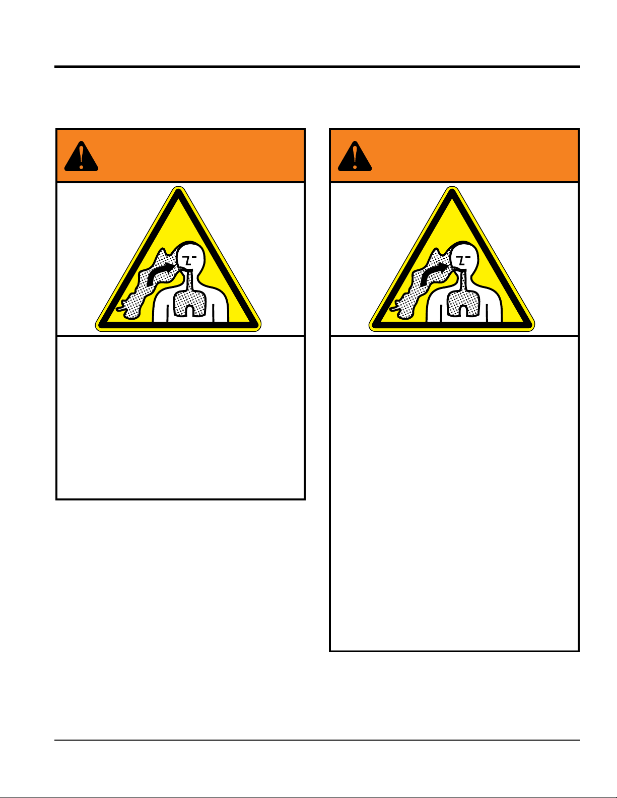
SILICOSIS/RESPIRATORY WARNINGS
WARNING
SILICOSIS WARNING RESPIRATORY HAZARDS
Grinding/cutting/drilling of masonry, concrete, metal and
other materials with silica in their composition may give
off dust or mists containing crystalline silica. Silica is a
basic component of sand, quartz, brick clay, granite and
numerous other minerals and rocks. Repeated and/or
substantial inhalation of airborne crystalline silica can
cause serious or fatal respiratory diseases, including
silicosis. In addition, California and some other
authorities have listed respirable crystalline silica as a
substance known to cause cancer. When cutting such
materials, always follow the respiratory precautions
mentioned above.
WARNING
Grinding/cutting/drilling of masonry, concrete, metal and
other materials can generate dust, mists and fumes
containing chemicals known to cause serious or fatal
injury or illness, such as respiratory disease, cancer,
birth defects or other reproductive harm. If you are
unfamiliar with the risks associated with the particular
process and/or material being cut or the composition of
the tool being used, review the material safety data
sheet and/or consult your employer, the material
manufacturer/supplier, governmental agencies such as
OSHA and NIOSH and other sources on hazardous
materials. California and some other authorities, for
instance, have published lists of substances known to
cause cancer, reproductive toxicity, or other harmful
effects.
Control dust, mist and fumes at the source where
possible. In this regard use good work practices and
follow the recommendations of the manufacturers or
suppliers, OSHA/NIOSH, and occupational and trade
associations. Water should be used for dust
suppression when wet cutting is feasible. When the
hazards from inhalation of dust, mists and fumes cannot
be eliminated, the operator and any bystanders should
always wear a respirator approved by NIOSH/MSHA for
the materials being used.
WM63-SERIES MIXER • OPERATION AND PARTS MANUAL — REV. #0 (069/27/12) — PAGE 3
Page 4

TABLE OF CONTENTS
WM63H5/WM63H8/WM63E
Plaster And Mortar Mixers
Proposition 65 Warning ........................................... 2
Silicosis/Respiratory Warnings ................................ 3
Table Of Contents .................................................... 4
Parts Ordering Procedures ...................................... 5
Safety Information ..............................................6-10
Safety Chain Connection ....................................... 11
Specifications ........................................................ 12
Dimensions ............................................................ 13
General Information ............................................... 14
Components .......................................................... 15
Inspection ......................................................... 16-17
Basic Engine .......................................................... 18
Electric Motor ................................................... 19-20
Paddle Blade Adjustment ...................................... 21
Start-Up ............................................................ 22-23
Operation ............................................................... 24
Maintenance (Engine) ......................................26-27
Maintenance (Mixer) ......................................... 28-33
Troubleshooting ................................................34-36
Wiring Diagram ...................................................... 37
Explanation Of Code In Remarks Column............. 38
Suggested Spare Parts ......................................... 39
Component Drawings
Nameplate And Decals ..................................... 40-41
Frame Assembly ............................................... 42-43
Paddle Shaft Assembly .....................................44-45
Steel Tub Assembly .......................................... 46-47
Drum And Paddle Shaft Complete Assembly ... 48-49
Axle Assembly .................................................. 50-51
Engine Assembly .............................................. 52-53
Electric Motor Assembly ................................... 54-55
Cabinet Assembly ............................................. 56-57
Terms And Conditions Of Sale — Parts ................ 56
NOTICE
Specifications and part numbers are subject to change
without notice.
PAGE 4 — WM63-SERIES MIXER • OPERATION AND PARTS MANUAL — REV. #0 (09/27/12)
Page 5
PARTS ORDERING PROCEDURES
Ordering parts has never been easier!
If you have an MQ Account, to obtain a Username
Effective:
Choose from three easy options:
January 1st, 2006
Best Deal!
Order via Internet (Dealers Only):
Order parts on-line using Multiquip’s SmartEquip website!
■ View Parts Diagrams
■ Order Parts
■ Print Specifi cation Information
Goto www.multiquip.com and click on
Order Parts
to log in and save!
Order via Fax (Dealers Only):
All customers are welcome to order parts via Fax.
Domestic (US) Customers dial:
1-800-6-PARTS-7 (800-672-7877)
Order via Phone:
Non-Dealer Customers:
Contact your local Multiquip Dealer for
parts or call 800-427-1244 for help in
locating a dealer near you.
and Password, E-mail us at: parts@multiquip.
com.
To ob ta in an MQ Account , contac t yo ur
District Sales Manager for more information.
Use the internet and qualify for a 5% Discount
on Standard orders for all orders which include
complete part numbers.*
Fax your order in and qualify for a 2% Discount
on Standard orders for all orders which include
complete part numbers.*
Domestic (US) Dealers Call:
1-800-427-1244
International Customers should contact
their local Multiquip Representatives for
Parts Ordering information.
Note: Discounts Are Subject To Change
Note: Discounts Are Subject To Change
When ordering parts, please supply:
❒ Dealer Account Number
❒ Dealer Name and Address
❒ Shipping Address (if different than billing address)
❒ Return Fax Number
❒ Applicable Model Number
❒ Quantity, Part Number and Description of Each Part
NOTICE
All orders are treated as Standard Orders and will
ship the same day if received prior to 3PM PST.
❒ Specify Preferred Method of Shipment:
✓ UPS/Fed Ex ✓ DHL
■ Priority One ✓ Truck
■ Ground
■ Next Day
■ Second/Third Day
www.multiquip.com
WE ACCEPT ALL MAJOR CREDIT CARDS!
WM63-SERIES MIXER • OPERATION AND PARTS MANUAL — REV. #0 (069/27/12) — PAGE 5
Page 6
SAFETY INFORMATION
Do not operate or service the equipment before reading
Potential hazards associated with the operation of this
the entire manual. Safety precautions should be followed
at all times when operating this equipment.
Failure to read and understand the safety
messages and operating instructions could
result in injury to yourself and others.
SAFETY MESSAGES
The four safety messages shown below will inform you
about potential hazards that could injure you or others. The
safety messages specifi cally address the level of exposure
to the operator and are preceded by one of four words:
DANGER, WARNING, CAUTION or NOTICE.
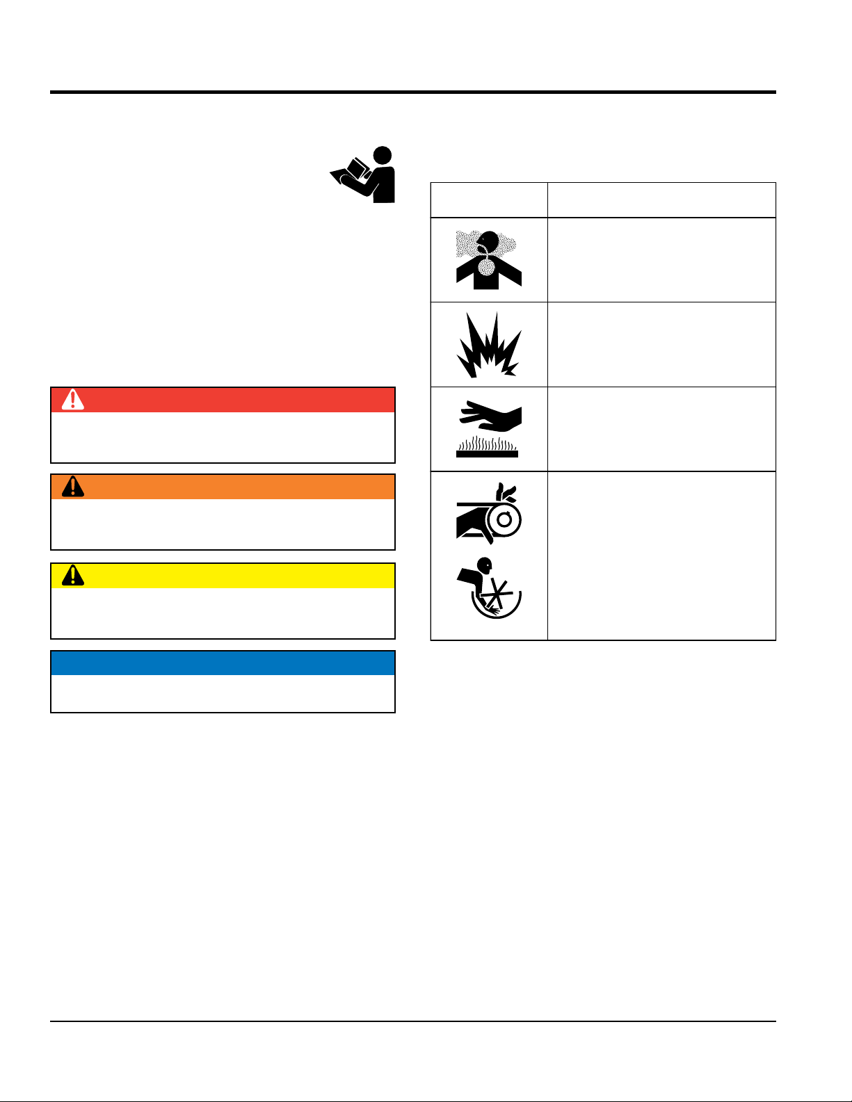
SAFETY SYMBOLS
DANGER
Indicates a hazardous situation which, if not avoided,
WILL result in DEATH or SERIOUS INJURY.
WARNING
Indicates a hazardous situation which, if not avoided,
COULD result in DEATH or SERIOUS INJURY.
CAUTION
equipment will be referenced with hazard symbols which
may appear throughout this manual in conjunction with
safety messages.
Symbol Safety Hazard
Lethal exhaust gas hazards
Explosive fuel hazards
Burn hazards
Rotating parts hazards
Indicates a hazardous situation which, if not avoided,
COULD result in MINOR or MODERATE INJURY.
NOTICE
Addresses practices not related to personal injury.
PAGE 6 — WM63-SERIES MIXER • OPERATION AND PARTS MANUAL — REV. #0 (09/27/12)
Page 7
GENERAL SAFETY
NOTICE
This equipment should only be operated by trained and
Whenever necessary, replace nameplate, operation and
accident due to equipment modifi cations. Unauthorized
recommended by Multiquip for this equipment. Damage
keep
Also, know the phone numbers
fi re department.
SAFETY INFORMATION
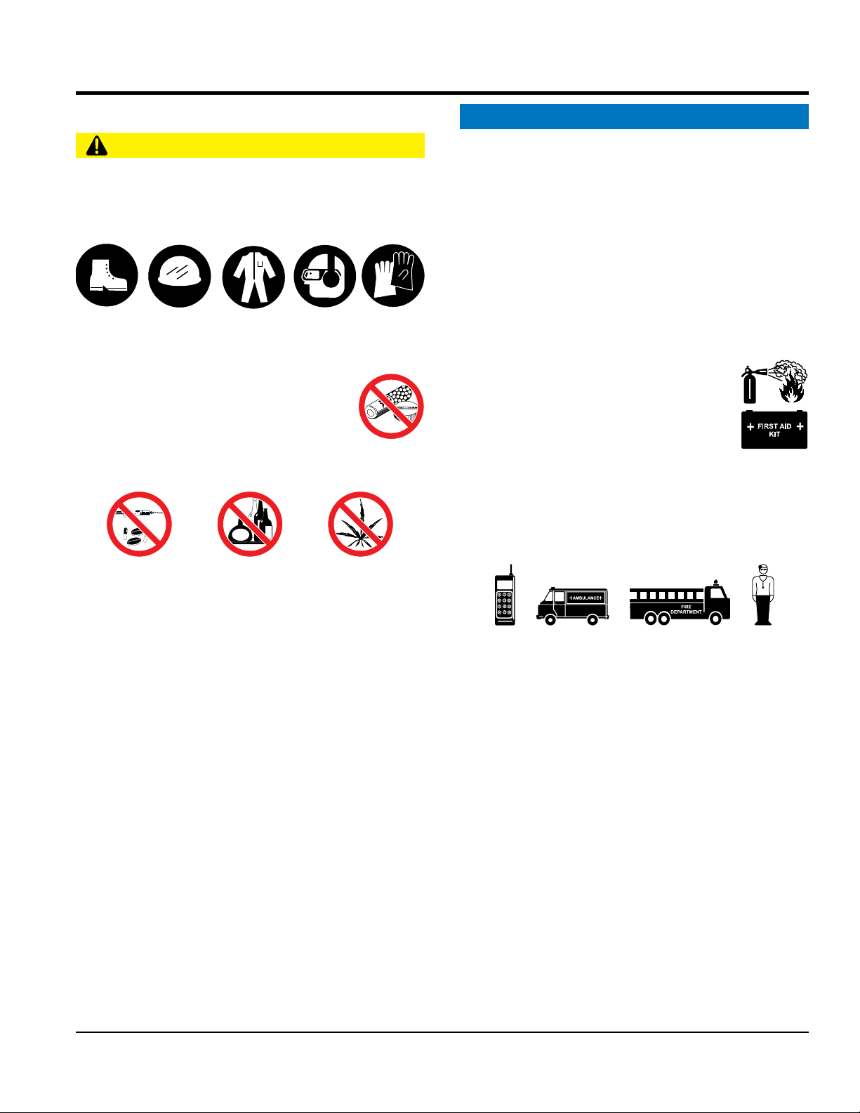
CAUTION
NEVER operate this equipment without proper protective
clothing, shatterproof glasses, respiratory protection,
hearing protection, steel-toed boots and other protective
devices required by the job or city and state regulations.
Avoid wearing jewelry or loose fi tting clothes that may
snag on the controls or moving parts as this can cause
serious injury.
NEVER operate this equipment when not
feeling well due to fatigue, illness or when
under medication.
NEVER operate this equipment under the
infl uence of drugs or alcohol.
ALWAYS clear the work area of any debris, tools, etc.
that would constitute a hazard while the equipment is
in operation.
qualifi ed personnel 18 years of age and older.
safety decals when they become diffi cult read.
Manufacturer does not assume responsibility for any
equipment modifi cation will void all warranties.
NEVER use accessories or attachments that are not
to the equipment and/or injury to user may result.
ALWAYS know the location of the nearest
fi re extinguisher.
ALWAYS know the location of the nearest
fi rst aid kit.
ALWAYS know the location of the nearest phone or
a phone on the job site.
of the nearest ambulance, doctor and
This information will be invaluable in the case of an
emergency.
ALWAYS check the equipment for loosened threads or
bolts before starting.
DO NOT use the equipment for any purpose other than
its intended purposes or applications.
WM63-SERIES MIXER • OPERATION AND PARTS MANUAL — REV. #0 (069/27/12) — PAGE 7
Page 8
SAFETY INFORMATION
MIXER SAFETY
ENGINE SAFETY (GASOLINE MODELS ONLY)
monoxide. This gas is colorless and odorless, and can
operate this equipment
tank and severely scald any persons in the general area
Make certain the operator knows how to and is capable
run engine without an air fi lter or with a dirty air
fi lter. Severe engine damage may occur. Service air fi lter
DANGER
NEVER operate the equipment in an explosive
atmosphere or near combustible materials. An
explosion or fi re could result causing severe
bodily harm or even death.
DO NOT mix fl ammable or explosive substances.
WARNING
NEVER place your hands inside the drum
while starting or operating this equipment.
NEVER di sco nne ct an y emerg enc y
or safety devices. These devices are
intended for operator safety. Disconnection of these
devices can cause severe injury, bodily harm or even
death. Disconnection of any of these devices will void
all warranties.
Before operating mixer, ensure that safety grate is in
position and correctly fi tted.
CAUTION
NEVER lubricate components or attempt service on a
running machine.
NOTICE
DANGER
Engine fuel exhaust gases contain poisonous carbon
cause death if inhaled.
The engine of this equipment requires an adequate
free fl ow of cooling air. NEVER
in any enclosed or narrow
area where free fl ow of the
air is restricted. If the air
fl ow is restricted it will cause
injury to people and property
and serious damage to the
equipment or engine.
WARNING
D O NOT pl ace hands o r fi ngers inside e ngine
compartment when engine is running.
NEVER operate the engine with heat shields or
guards removed.
Keep fi ngers, hands hair and clothing away
from all moving parts to prevent injury.
DO NOT remove the engine oil drain plug
while the engine is hot. Hot oil will gush out of the oil
DANGEROUS
GAS FUMES
ALWAYS keep the machine in proper running condition.
ALWAYS ensure mixer is on level ground before mixing.
Fix damage to machine and replace any broken parts
immediately.
DO NOT tip mixer onto drum mouth when the drum is
rotating.
Ensure the drum is rotating while fi lling and emptying
the drum.
ALWAYS store equipment properly when it is not being
used. Equipment should be stored in a clean, dry location
out of the reach of children and unauthorized personnel.
PAGE 8 — WM63-SERIES MIXER • OPERATION AND PARTS MANUAL — REV. #0 (09/27/12)
of the mixer.
CAUTION
NEVER touch the hot exhaust manifold,
muffl er or cylinder. Allow these parts to cool
before servicing equipment.
of turning the engine OFF in case of an emergency.
NOTICE
NEVER
frequently to prevent engine malfunction.
NEVER tamper with the factory settings
of the engine or engine governor. Damage
to the engine or equipment can result
if operating in speed ranges above the
maximum allowable.
Page 9
SAFETY INFORMATION
FUEL SAFETY (GASOLINE MODELS ONLY)
Power Cord/Cable Safety
cables or cords when
Ensure that cables and cords will not be tripped over or
make certain that proper power or extension
allow any person or animal to stand underneath
make sure forklift forks are inserted into pockets
(if applicable) as far as possible when lifting the mixer.
tip the engine to extreme angles during lifting as
it may cause oil to gravitate into the cylinder head, making
DANGER
DO NOT start the engine near spilled fuel or combustible
fl uids. Fuel is extremely fl ammable and its vapors can
cause an explosion if ignited.
ALWAYS refuel in a well-ventilated area, away from
sparks and open fl ames.
ALWAYS use extreme caution when working with
fl ammable liquids.
DO NOT fi ll the fuel tank while the engine is running
or hot.
DO NOT overfi ll tank, since spilled fuel could ignite if it
comes into contact with hot engine parts or sparks from
the ignition system.
Store fuel in appropriate containers, in well-ventilated
areas and away from sparks and fl ames.
NEVER use fuel as a cleaning agent.
DO NOT smoke a round or ne ar th e
equipment. Fire or explosion could result
from fuel vapors or if fuel is spilled on a
hot engine.
DANGER
NEVER let power cords or cables lay in water.
NEVER use damaged or worn
connecting equipment to generator. Inspect for cuts in
the insulation.
NEVER grab or touch a live power
cord or cable with wet hands. The
possibility exists of electrical shock,
electrocution or death.
Make sure power cables are securely connected.
Incorrect connections may cause electrical shock and
damage to the mixer.
CAUTION
trapped underneath the mixer.
NOTICE
ALWAYS
cord has been selected for the job.
TRANSPORTING SAFETY
GENERATOR SAFETY
If using a generator to power mixer, refer to
applicable generator manual safety information
section.
ELECTRIC MOTOR SAFETY
(ELECTRIC MODELS ONLY)
NOTICE
Operate electric motor only at the specifi ed voltage
indicated on the nameplate.
DO NOT spray water onto electric motor.
ALWAYS disconnect AC power plug from power source
before moving mixer.
ALWAYS make sure the ON/OFF switch
on the electric motor is in the OFF position
when not in use and before inserting the
mixer’s power plug into an AC receptacle.
CAUTION
NEVER
the equipment while lifting.
NOTICE
ALWAYS
ALWAYS shutdown engine before transporting.
NEVER lift the equipment while the engine is running.
Tighten fuel tank cap securely and close fuel cock to
prevent fuel from spilling.
DO NOT lift machine to unnecessary heights.
ALWAYS tie down equipment during transpor t by
securing the equipment with rope.
NEVER
the engine start diffi cult.
WM63-SERIES MIXER • OPERATION AND PARTS MANUAL — REV. #0 (069/27/12) — PAGE 9
Page 10

SAFETY INFORMATION
TOWING SAFETY
ENVIRONMENTAL SAFETY
pour waste, oil or fuel directly onto the ground,
CAUTION
Check with your local county or state safety towing
regulations, in addition to meeting Department of
Transportation (DOT) Safety Towing Regulations,
before towing your mixer.
In order to reduce the possibility of an accident while
transporting the mixer on public roads, ALWAYS make
sure the towing vehicle is mechanically sound and in
good operating condition.
ALWAYS shutdown engine before transporting.
ALWAYS inspect the hitch and coupling for wear. NEVER
tow a mixer with defective hitches, couplings, chains, etc.
Check the tire air pressure on both towing vehicle and
mixer Mixer tires should be infl ated to 50 psi cold. Also
check the tire tread wear on the vehicle and mixer.
ALWAYS make sure the mixer is equipped with a safety
chain.
ALWAYS properly attach mixer’s safety chains to towing
vehicle.
NOTICE
Dispose of hazardous waste properly.
Examples of potentially hazardous waste
are used motor oil, fuel and fuel fi lters.
DO NOT use food or plastic containers to dispose of
hazardous waste.
DO NOT
down a drain or into any water source.
The maximum speed for highway towing is 55 MPH unless
posted otherwise. Recommended off-road towing is not to
exceed 15 MPH or less depending on type of terrain.
Avoid sudden stops and starts. This can cause skidding,
or jack-knifi ng. Smooth, gradual starts and stops will
improve towing.
Avoid sharp turns to prevent rolling.
Mixer should be adjusted to a level position at all times
when towing.
Raise and lock mixer wheel stand in up position when
towing.
Place chock blocks underneath wheel to prevent rolling
while parked.
PAGE 10 — WM63-SERIES MIXER • OPERATION AND PARTS MANUAL — REV. #0 (09/27/12)
Page 11
DRUM LATCH
SAFETY CHAIN CONNECTION
CAUTION
NEVER tow the mixer with the safety chain removed.
The safety chain is intended to prevent complete
separation of the mixer from the towing vehicle in the
event of a tow bar failure.
TOW BAR TO MIXER CONNECTION
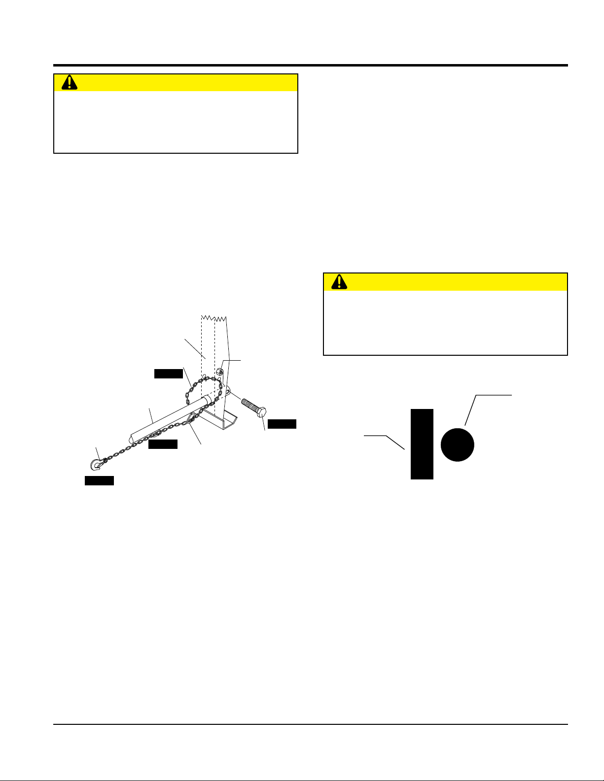
Reference Figure 1 for the installation of the safety chain.
1. Insert the tow bar through the round opening at the
bottom of the mixer stand.
Align the hole on the tow bar with the hole on the mixer
frame, and insert 1/2-inch bolt through tow bar and
frame. Secure tow bar to frame with 1/2-inch nyloc nut.
Tighten to 40 ft.-lbs.
MIXER
STAND
1/2-INCH NYLOCK
SAFETY CHAIN
STEP 2
NUT, GRADE 5
2. Route the safety chain through the holes just above
the tow bar, located on each side of the mixer stand.
Loop the chain together and place under the tow bar.
Secure the loop with the connector link.
3. Extend the safety chain along the length of the tow bar,
looping it through the tow bar's connector link. Remove
any excess chain slack.
4. Connect the free end of (connector link) the safety
chain to the towing vehicle. Remember it is critical that
the length of the chain be properly adjusted, to prevent
the draw bar and the front of the mixer stand from
dropping to the ground (contact) in the event the draw
bar becomes disconnected from the towing vehicle.
CAUTION
DO NOT tow the mixer unless the mixing drum is
completely empty. ALWAYS make sure the drum latch
pin is fully engaged to the right (Figure 2) of the drum
stop block. This will keep the drum from rotating.
TOW BAR
CONNECTOR LINK
SAFETY CHAIN
CLEVIS SAFETY HOOK
(TOWING VEHICLE)
STEP 4
STEP 3
SAFETY CHAIN
CONNECTOR LINK
STEP 1
1/2-INCH BOLT,
GRADE 5
Figure 1. Tow Bar and Safety Chain Installation
PIN
STOP
BLOCK
TOW OR LOCKED
POSITION
Figure 2. Drum Latch Pin
(Tow or Locked Position)
WM63-SERIES MIXER • OPERATION AND PARTS MANUAL — REV. #0 (069/27/12) — PAGE 11
Page 12
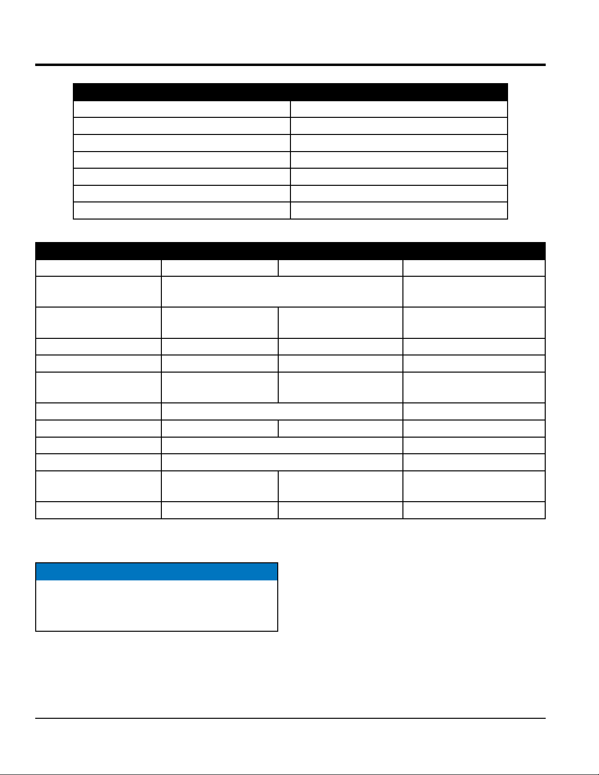
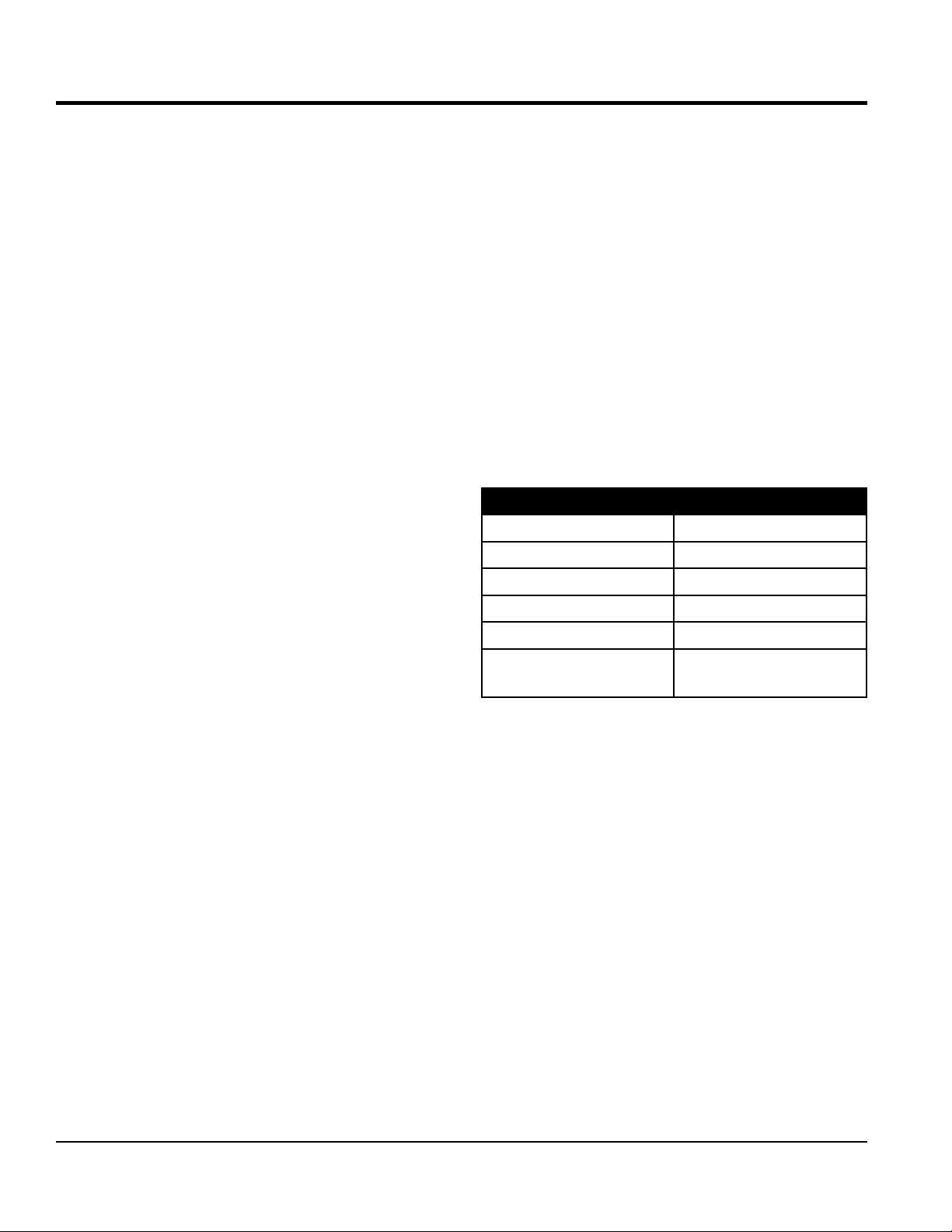
Table 1. Mixer Specifications
SPECIFICATIONS
Capacity
Bag Capacity
Weight
Height W/Dump Handle
Discharge Height
Drive
Dump Action
Table 2. Engine Specifications
Model Honda GX160UT1HX2 HONDA GX240UT1HA2 Baldor
Type
Bore X Stroke
Displacement
Max Output
Fuel Tank Capacity
Air-cooled 4 stroke, Single Cylinder, OHV,
Horizontal Shaft Gasoline Engine
2.70 in. X 1.80 in.
(68 mm x 45 mm)
9.9 cu. in. (163 cc) 14.81 cu. in. (242 cc) N/A
4.8 H.P./3600 R.P.M. 7.1 H.P./3600 R.P.M. 1.5 HP/1725 RPM
Approx. 0.95 U.S. Gallons
(3.6 Liters)
2.90 in. X 2.30 in.
(73 mm x 58 mm)
Approx. 1.59 U.S. Gallons
(6 Liters)
6.3 cu. ft (178 liters)
1-1/2 to 2-1/2 bags
574 lbs. (260 kg.)
73 in. (185 cm.)
17.5 in. (44.4 cm.)
V-Belt/Gear
Manual
1.5 HP, 115/230V Single-Phase
Electric Motor
N/A
N/A
Fuel
Lube Oil Capacity
Speed Control Method
Starting Method
Dimensions (L x W x H)
Dry Net Weight
NOTICE
In accordance with our established policy of constant
improvement, we reserve the right to amend these
specifications at any time without notice.
0.63 qt. (0.6 liter) 1.16 qt. (1.1 liter) N/A
12.3 x 14.3 x 13.6 in.
(312 x 362 x 346 mm)
40.8 lbs. (15 Kg.) 55.1 lbs. (25 Kg.) Approx. 22 lbs. (10 Kg.)
Unleaded Gasoline N/A
Centrifugal Flyweight Type N/A
Recoil Start N/A
15 X 17 X 16.6 in.
(380 X 430 X 422 mm)
13.3 X 8.7 X 9.06 in.
(380 X 430 X 422 mm
PAGE 12 — WM63-SERIES MIXER • OPERATION AND PARTS MANUAL — REV. #0 (09/27/12)
Page 13

DIMENSIONS
Table 3. Dimensions
Description Dimensions in. (cm)
C
Length (w/Tow Bar) 67 in. (170 cm)
Width 50 in. (127 cm)
Height 56 in. (142 cm)
A
OPTIONAL TOW BARS
APPROXIMATE LENGTH
36 IN. (91.44 CM)
HBC-1
2-INCH
BALL COUPLER
HPC-1
1-INCH
PIN COUPLER
B
HLC-1
LOOP COUPLER
Figure 3. Dimensions
WM63-SERIES MIXER • OPERATION AND PARTS MANUAL — REV. #0 (069/27/12) — PAGE 13
Page 14
GENERAL INFORMATION
APPLICATION
The MQ Whiteman WM63 Series mixers (drum capacity
of 6.3 cu. ft./178 liters) are shipped completely assembled
and have been factory tested and are ready for use.
This mixer is only intended for the production of plaster and
mortar. The mixer must be used for its intended purpose
and is not suitable for the mixing of flammable or explosive
substances. The mixer must not be used in an explosive
atmosphere. This mixer has a batch capacity between 2-1/2
and 3-1/2 bags.
POWER PLANTS
The WM63 Series mixer can be equipped with either a
Honda GX160 or GX240 air-cooled, 4-stroke gasoline
engine. In addition this mixer is also available with a 1.5
HP electric motor with that can be configured for either
115 or 230 VAC operation by means of a voltage selector
switch. Refer to Table 2 for specific engine or electric motor
information.
ELECTRICAL
If mixer is equipped with an electric motor, make sure that
the power being supplied to the motor corresponds to the
voltage rating label on the motor. Supplying the wrong
voltage to the electric motor will cause severe electrical
damage to the motor.
Ensure that the extension cable is carefully laid out avoiding
wet areas, sharp edges and locations where vehicles might
run over it. Avoid allowing the extension cable to be trapped
underneath the mixer.
Unroll the extension cable fully or it will overheat and could
catch fire. Make sure that all extension cable connections
are dry and safe. Replace any defective or badly worn
extension cable immediately.
HARDWARE
Check all hardware on the mixer before starting. Periodically
inspect all hardware. Loose hardware can contribute
to early component failure and poor performance. Use
Table 4 as a general guideline when torqueing of mixer
hardware is required. Remember to keep all mixer hardware
components tight.
Table 4. Hardware Torque Recommendations
Hardware Diameter Torque (ft-lbs)
5/16-inch x 18 14
3/8-inch x 16 24
3/8-inch x 24 37
1/2-inch x 13 39
1/2-inch x 13
(Grade 8)
90
Always make sure the OFF/ON switch on the electric motor
is in the OFF position before applying power.
It is strongly recommended when inserting the mixer's
power cord into a receptacle, that a G.F.C.I. (Ground
Fault Current Interrupter) receptacle be used (115 VAC
applications).
Extension Cables
The extension cable should be a 3-wire configuration that
includes a ground wire that conforms to UL code. The wire
cross section must be a minimum of 2.5 mm2. Choose an
extension cord of adequate current carrying capacity as
referenced in Table 6. Remember cable distance affects
the current-voltage capacity of the extension cable.
PAGE 14 — WM63-SERIES MIXER • OPERATION AND PARTS MANUAL — REV. #0 (09/27/12)
ENGINE MAINTENANCE
For basic engine maintenance, refer to the engine
maintenance section in this manual. For a more detailed
engine maintenance, refer to the Honda Engine Owner's
manual furnished with the engine.
Page 15
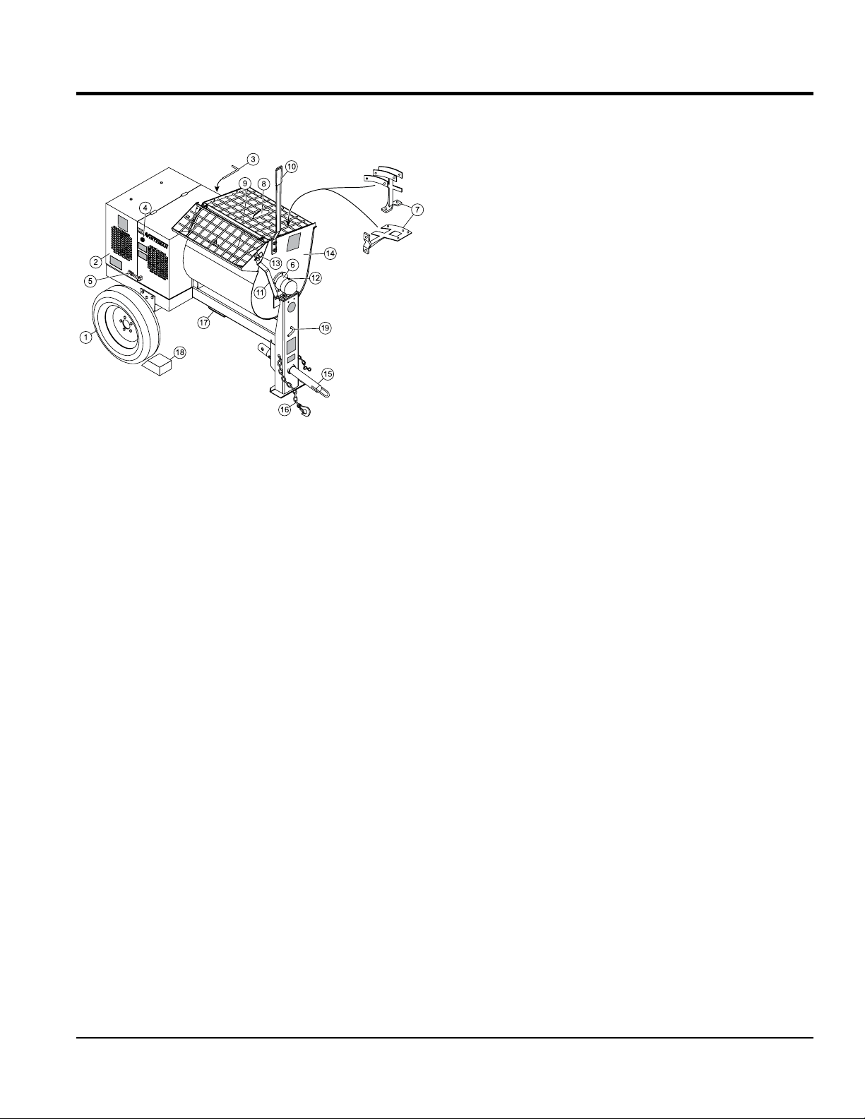
COMPONENTS
Figure 4 illustrates the basic components and controls of
the WM63 Series mixer.
Figure 4. Mixer Components
1. Tires Ply — The tire ply (layers) number is rated in
letters. This mixer uses 13-inch 4-ply tires.
2. Engine Cover — Lift this cover to gain access to the
engine compartment.
3. Belt Slip Lever — When starting, this lever should
be move upward and to the left. For mixing, place the
lever in the down position. See attached decal located
adjacent to lever.
4. ON/OFF Switch — This switch is located on the side
of the engine cover. When activated, it will shut down
the engine.
5. Latch — Use this latch to se cure the engine
compartment cabinet.
6. Drum Bearing — There is a sealed bearing on
each end of the mixing drum. Bearings are packed
and sealed at the factory and require no further
maintenance.
7. Mixing Paddles — Used in the mixing of material. This
unit uses four different types of paddles to provide a
fast uniform mix.
8. Bag Cutter — This feature allows compound mixing
bags to be opened easily, therefore allowing the
contents of the bag to fall directly into the mixing drum.
9. Safety Grill — Provided for operator safety. This safety
grill is designed to keep hands and solid objects out of
the mixing drum when in use. This grill should be closed
at all times when mixer is in use. DO NOT remove the
grill or grill opening bar. Keep the grill clean by washing
it down daily.
10. Dump Handle — Pull this handle downward to dump
the contents of the drum. Push the handle upward to
return the drum to its vertical position.
11. Safety Grill Lock Handle — To prevent injury to hands
and arms, the safety grill should ALWAYS be locked
when the mixing of plaster or mortar is required. Also
when transporting the mixer, the safety grill should be
locked. The safety grill should only be unlocked when
cleaning of the blades and drum is required.
12. Pivot Point/Zerk Fitting — There is a zerk grease
fitting on each end of the mixing drum. These fittings
lubricate the dumping mechanism. Lubricate both
fittings at least twice a week.
13. Dump Handle Release Pin — Pull this pin outward
(spring loaded) to release the drum, then pull down
on the dump handle to place the drum in the dump
position. When drum is in dump position, pin will
automatically lock drum.
14. Mixing Drum — Mixing materials such as mortar,
plaster are to be placed into this drum for mixing.
Always clean the drum after each use.
15. Tow Bar/Coupler — This mixer uses a 2-inch coupler
or pintle towbar.
16. Safety Chain — This mixer uses a 3/16-inch thick,
72-inches long, zinc-plated safety chain. ALWAYS
connect the safety chain when towing.
17. Forklift Pockets — When lifting of the mixer is
required, use these fork lift pockets to lift the mixer.
Remember to insert the forks of the forklift a minimum
of 24 inches into the lift pockets.
18. Chock Blocks — Place these blocks (not included as
part of the mixer package) under each mixer wheel to
prevent rolling.
19. Drum Latch Pin — Place pin to the right to prevent
drum from rotating. Place pin to the left to rotate (tilt)
drum.
WM63-SERIES MIXER • OPERATION AND PARTS MANUAL — REV. #0 (069/27/12) — PAGE 15
Page 16
INSPECTION
LOWER LIMIT
BEFORE STARTING
1. Read all safety instructions at the beginning of manual.
2. Clean the unit, removing dirt and dust, particularly the
engine cooling air inlet, carburetor and air cleaner.
3. Check the air filter for dirt and dust. If air filter is dirty,
replace air filter with a new one as required.
4. Check carburetor for external dirt and dust. Clean with
dry compressed air.
5. Check fastening nuts and bolts for tightness.
CAUTION
ALWAYS wear approved eye and hearing
protection while operating the mixer.
CAUTION
NEVER place hands or feet inside the
engine guard cover while the engine is
running. ALWAYS shut the engine down
before performing any kind of maintenance
service on the mixer.
5. I
NOTICE
Reference engine manufacturer’s manual for specific
servicing instructions.
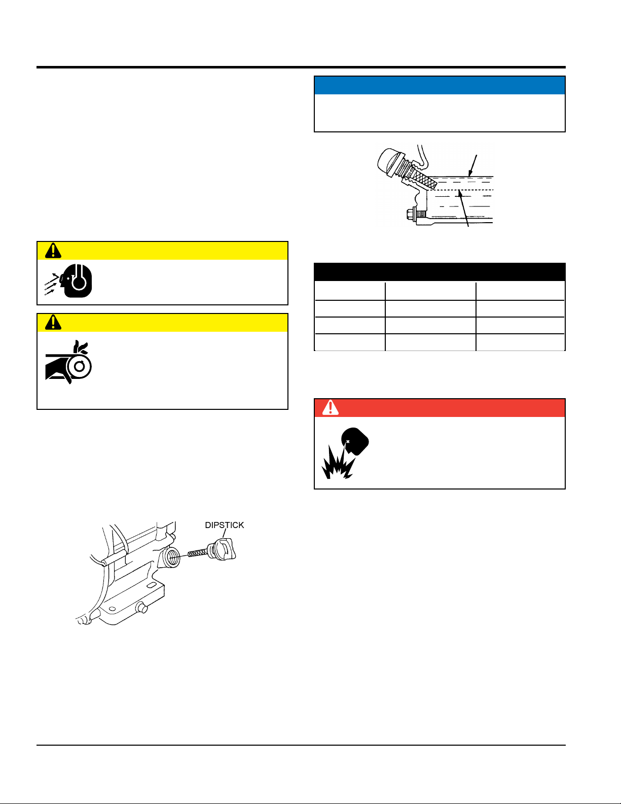
UPPER LIMIT
Figure 6. Engine Oil Dipstick (Oil Level)
Table 5. Oil Type
Season Temperature Oil Type
Summer 25°C or Higher SAE 10W-30
Spring/Fall 25°C ~ 10°C SAE 10W-30/20
Winter 0°C or Lower SAE 10W-10
FUEL CHECK
DANGER
ENGINE OIL CHECK
1. To check the engine oil level, place the unit on secure
level ground with the engine stopped.
2. Remove the filler dipstick from the engine oil filler hole
(Figure 5) and wipe it clean.
Figure 5. Engine Oil Dipstick (Removal)
3. Insert and remove the dipstick without screwing it into
the filler neck. Check the oil level shown on the dipstick.
4. f the oil level is low (Figure 6), fill to the edge of the
oil filler hole with the recommended oil type (Table 5).
Maximum oil capacity is 2.33 pints (1.09 liters).
Motor fuels are highly flammable and can be
dangerous if mishandled. DO NOT smoke
while refueling. DO NOT attempt to refuel the
mixer if the engine is hot or running.
1. Remove the gasoline cap located on top of fuel tank.
2. Visually inspect to see if fuel level is low. If fuel is low,
replenish with unleaded fuel.
3. When refueling, be sure to use a strainer for filtration.
DO NOT top-off fuel. Wipe up any spilled fuel
immediately.
PAGE 16 — WM63-SERIES MIXER • OPERATION AND PARTS MANUAL — REV. #0 (09/27/12)
Page 17
INSPECTION
MISSING
RUBBER
CRACKS
BLADE
PADDLE
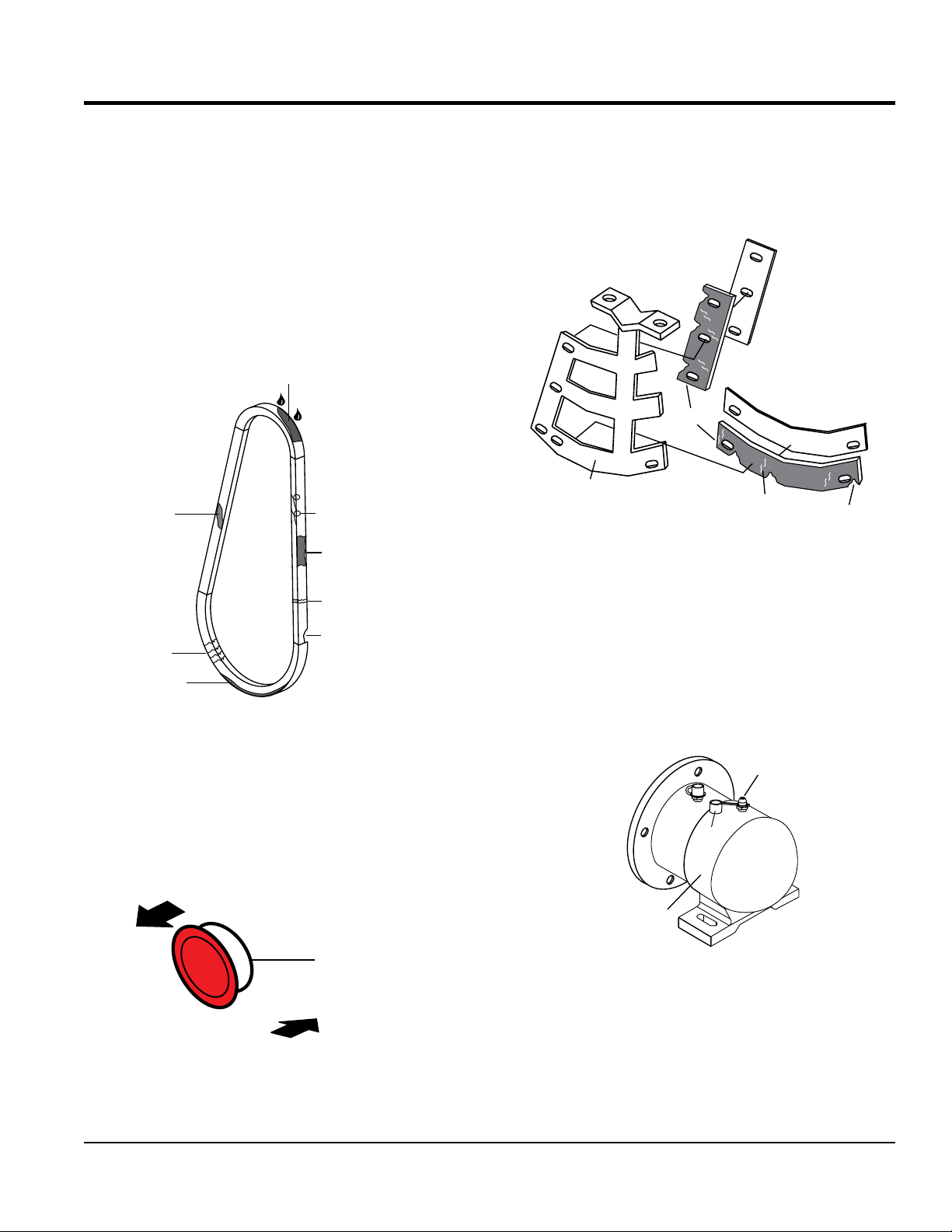
V-BELT CHECK
Visually examine the V-belt (Figure 7) and determine if it
is full of tiny cracks, frayed, has pieces of rubber missing,
is peeling or otherwise damaged.
Also, examine the belt and determine if it is oil soaked or
"glazed " (hard shiny appearance on the sides of the belt).
Either of these two conditions can cause the belt to run hot,
which can weaken it and increase the danger of it breaking.
If the V-belt exhibits any of the above wear conditions
replace the V-belt immediately.
OIL SOAKED
GLAZED
CORD FAILURE
WORN BACK
COVER
BROKEN
Check for worn or defective paddle blades (Figure 9).
Make sure that all blades are adjusted properly. See blade
adjustment procedure (Figure 13) in this manual. Replace
all defective or damaged blades immediately.
E
S
N
C
D
R
A
P
E
R
S
I
D
E
S
C
R
A
P
E
R
Figure 9. Blade Inspection
GREASE FITTINGS (DUMPING MECHANISM)
MISSING RUBBER
CRACKS
SIDEWALL
WEAR
Figure 7. V-Belt Inspection
START/STOP SWITCH
This unit has been equipped with a start/stop switch
(Figure 8), which should be tested every time the unit is
started.
PULL OUT
TO START ENGINE
START/STOP
SWITCH
PUSH IN
TO STOP ENGINE
Check the drum bearing bracket grease fittings (Figure 10) at
each end of the mixing drum. These grease fittings lubricate
the dumping mechanism. If the dumping handle is stiff or
hard to move, lubricate these grease fittings.
GREASE
FITTING
CAP
DRUM
BEARING
BRACKET
Figure 10. Grease Fittings
Drum Bearing Bracket
Figure 8. Start/Stop SwitchBLADE CHECK
WM63-SERIES MIXER • OPERATION AND PARTS MANUAL — REV. #0 (069/27/12) — PAGE 17
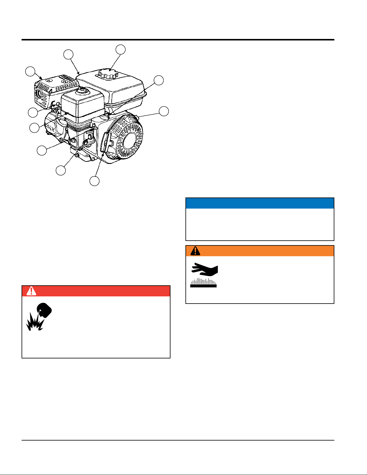
Page 18
BASIC ENGINE
10
9
8
7
6
5
4
Figure 11. Engine Components
1
2
3
INITIAL SERVICING
The engine (Figure 11) must be checked for proper
lubrication and filled with fuel prior to operation. Refer to the
engine manufacturer’s manual for instructions and details
of operation and servicing.
2. Throttle Lever — Used to adjust engine RPM speed
(lever advanced forward SLOW, lever back toward
operator FAST).
3. Engine ON/OFF Switch — ON position permits engine
starting, OFF position stops engine operations.
4. Recoil Starter (pull rope) — Manual-starting method.
Pull the starter grip until resistance is felt, then pull
briskly and smoothly.
5. Fuel Valve Lever — OPEN to let fuel flow, CLOSE to
stop the flow of fuel.
6. Choke Lever — Used in the starting of a cold engine,
or in cold weather conditions. The choke enriches the
fuel mixture.
7. Air Cleaner — Prevents dirt and other debris from
entering the fuel system. Remove wing-nut on top of
air filter cannister to gain access to filter element.
NOTICE
Operating the engine without an air filter, with a
damaged air filter, or a filter in need of replacement will
allow dirt to enter the engine, causing rapid engine wear.
WARNING
1. Fuel Filler Cap — Remove this cap to add unleaded
gasoline to the fuel tank. Make sure cap is tightened
securely. DO NOT over fill.
DANGER
Adding fuel to the tank should be done
only when the engine is stopped and has
had an opportunity to cool down. In the
event of a fuel spill, DO NOT attempt to
start the engine until the fuel residue has
been completely wiped up, and the area surrounding
the engine is dry.
Engine components can generate extreme
heat. To prevent burns, DO NOT touch
these areas while the engine is running or
immediately after operating. NEVER operate
the engine with the muffler removed.
8. Spark Plug — Provides spark to the ignition system.
Set spark plug gap to 0.6 - 0.7 mm (0.028 - 0.031 inch)
Clean spark plug once a week.
9. Muffler — Used to reduce noise and emissions.
10. Fuel Tank — Holds unleaded gasoline. For additional
information refer to engine owner's manual.
PAGE 18 — WM63-SERIES MIXER • OPERATION AND PARTS MANUAL — REV. #0 (09/27/12)
Page 19

ELECTRIC MOTOR
ELECTRIC MOTOR
For maintenance care and operation of the electric motor,
refer to your electric motor instruction booklet furnished
with the motor.
Protect the electric motor from dust as much as possible
and keep ventilating openings clean.
CAUTION
DO NOT spray water at any time on the electric motor.
DO NOT operate electric motor in a explosive environment.
The electric motor used in this mixer is a single-phase 3
HP motor. The input voltage requirement for this motor is
115/230 VAC, and has been pre-set to 230VAC.
ELECTRIC MOTOR CONNECTION
A 12-inch electrical cable (Figure 7) is provided with the
electrical motor for hookup to a power source. Table 5 shows
the required NEMA connector for the desired motor
horsepower rating. In addition, Table 5 also shows the
matching NEMA approved connector for the required
extension cord.
NOTICE
ALWAYS make certain that the power source required for
the electric motor is correct and always use the correct
NEMA configuration plug. Failure to supply the correct
voltage to the motor can severely damage the motor.
Table 6. Electric Motor Wiring Information
Motor
Horsepower
Rating
1.5 HP
(115 VAC)
1.5 HP
(230 VAC)
L5-20P PLUG
(115 VAC)
L6-20P PLUG
(230 VAC)
CONNECT
TO POWER
SOURCE
115-230 VAC - Single Phase
NEMA
Plug
L5-20P
P/N EM940537
L6-20P
P/N EM940539
OFF/ON
SWITCH
SINGLE
ON
PHASE
115/230 VAC
2.0 HP
ELECTRIC
OFF
MOTOR
L5-20R
RECEPTACLE
(115 VAC)
G
W
VOLTAGE
LOCKOUT
SELECTOR
BOLT
Mating NEMA
Receptacle
L5-20R
P/N EM940538
L6-20R
P/N EM940540
VOLTAGE
SELECTOR
SWITCH
115
230
GREASE
FITTING
VOLTAGE
SWITCH
VOLTAGE
LOCKOUT
BOLT
NOTICE
It is strongly recommended that all electrical wiring be
done by a licensed electrician.
Special attention should be given to the electric switch as
well as the over-and-under voltage protection devices as
per regulations set forth in the local electrical safety code
handbook.
WM63-SERIES MIXER • OPERATION AND PARTS MANUAL — REV. #0 (069/27/12) — PAGE 19
L6-20R
RECEPTACLE
(230 VAC)
Figure 12. Single Phase Electric Motor With
12-inch Pigtail
Page 20

The electric motor supplied is wired for 115 VAC grounded
operation. Make certain that the correct size grounded
(3-wires) extension cord is used. See Table 7 below.
Table 7. Recommended Extension Cord Sizes
Model Motor Voltage
WM63E 1.5 HP
115 VAC No. 12 No. 10 No. 8 No. 6
230 VAC No. 14 No. 12 No. 12 No. 8
50 ft.
(15.24 m)
75 ft.
(22.86 m)
100 ft.
(30.48 m)
200 ft.
(60.96 m)
Motors can burn out when the line voltage falls 10% below
the voltage rating of the motor. Failure to use proper voltage
will cause the motor to overheat and actuate the overload
switch.
If overload protection should actuate because of improper
voltage or any other malfunction, turn the main switch on
the motor to the "OFF" position and correct the problem,
press the reset switch button, and turn the main switch to
the "ON" position.
ELECTRIC MOTOR
ELECTRIC MOTOR VOLTAGE SWITCH
ALWAYS make certain the electric motor switch is "OFF"
and the power cord has been disconnected from the
power source.
Remove the voltage lock-out bolt (Figure 12). Change
the position of the voltage change toggle switch from
115 VAC to 230 VAC. The mixer is factory wired for 115
VAC operation.
Replace the voltage lock-out bolt.
Important!, when changing the input voltage to the motor
from 115 to 230 VAC, the plug on the motor power cord
must also be changed. See Table 6
PAGE 20 — WM63-SERIES MIXER • OPERATION AND PARTS MANUAL — REV. #0 (09/27/12)
Page 21

Adjust paddles as shown in Figure 13.
CAST PADDLE
ENGINE END
CAST PADDLE
PADDLE BLADE ADJUSTMENT
TOW END
CENTER TOW END
CAST PADDLE
DRUM END
PADDLE BLADE IS TOO
TIGHT AGAINST DRUM
SIDE WALLS.
INCORRECT
CORRECT
CENTER ENGINE
END CAST PADDLE
SIDE PADDLE BLADE
ROTATION
DRUM SIDE
INCORRECT
ROTATION
END PADDLE BLADE
INCORRECT
CORRECT
PADDLE BLADE IS TOO
TIGHT AGAINST DRUM
SIDE WALLS.
DRUM END AND SIDE WALLS
Figure 13. Paddle Blade Adjustment
WM63-SERIES MIXER • OPERATION AND PARTS MANUAL — REV. #0 (069/27/12) — PAGE 21
Page 22

START-UP
This section is intended to assist the operator with the initial
start-up of the unit. It is extremely important that
this section be read carefully before attempting
to use the mixer in the field. DO NOT use your
mixer until this section is thoroughly understood.
WARNING
Failure to understand the operation of the mixer could
result in severe damage to the mixer or personal injury.
See Figure 4 for the location of any control referenced
in this manual.
CAUTION
NEVER operate the mixer in a confined
area or enclosed area structure that does
not provide ample free flow of air.
The following steps outline the procedure for starting the
engine.
1. Move the fuel shut-off lever (Figure 14) to the ON
position.
3. Move the throttle lever (Figure 16) away from the slow
position, about 1/3 of the way toward the fast position.
Figure 16. Throttle Lever
4. Turn the engine switch (Figure 17) to the ON position.
Figure 14. Fuel Shut-Off Lever
2. To start a cold engine, move the choke lever (Figure
15) to the CLOSED position.
Figure 17. Engine On/Off Switch
5. The main start/stop switch located on the engine cover
(Figure 18) is used to start and stop the engine. Pull
this switch outward to start the engine.
PULL OUT
TO START ENGINE
Figure 18. Start/Stop Switch
Figure 15. Choke Lever
PAGE 22 — WM63-SERIES MIXER • OPERATION AND PARTS MANUAL — REV. #0 (09/27/12)
Page 23

6. Place the belt slip lever (Figure 19) in the START/STOP
DRUM LATCH
(disengaged) position.
START-UP
PIN
START/STOP
POSITION
BELT SLIP
LEVER
Figure 19. Belt Slip Lever
(Start/Stop Position)
CAUTION
Make certain the drum lock pin (Figure 20
and Figure 21) is placed to the RIGHT (when
viewing the mixer from the towpole end) of
the drum stop block which is welded to the
front side of the drum. Also make sure lock pin is fully
engaged (locked). This will prevent the drum from tipping.
STOP
BLOCK
TOW OR LOCKED
POSITION
Figure 21. Drum Lock Pin (Right Position)
7. Pull the starter grip (Figure 22) lightly until you feel
resistance, then pull briskly. Return the starter grip
gently.
FRONT
POST
DRUM
Figure 20. Drum Lock Pin (Side-View)
LOCK
PIN
Figure 22. Starter Grip
8. Place the belt slip lever (Figure 23) in the mix position.
This will tilt the engine placing tension on the V-belts
enabling the shaft to rotate.
MIX
POSITION
BELT SLIP
LEVER
Figure 23. Belt Slip Lever (Mix Position)
WM63-SERIES MIXER • OPERATION AND PARTS MANUAL — REV. #0 (069/27/12) — PAGE 23
Page 24

OPERATION
DRUM LATCH
STAND CLEAR OF DUMP HANDLE.
MIXING/DUMPING
1. The paddle shaft inside the drum should be rotating
at this time.
2. Add a small amount water to the mixing drum.
3. Lift the mixing bag compound onto the steel safety
grate over the bag cutter and let the contents fall into
the drum. Add more water if desired and mix compound
to desired consistency.
4. When charging, mixing, or dumping a batch of plaster
or mortar the drum lock pin should be placed to the left
(when viewing the mixer from the towpole end) of the
drum stop block which is welded to the front side of
the drum. See Figure 24.
STOP
PIN
BLOCK
HANDLE KICK-BACK IS POSSIBLE.
Figure 25. Stand Clear of Dump Handle
STOPPING THE MIXER (GASOLINE)
1. Place the belt slip lever in the start/stop position (Figure
19).
2. Push the main start/stop switch (Figure 18) inward to
stop the engine.
3. Turn the fuel shut-off valve to the OFF position.
Figure 24. Drum Lock Pin (Left Position)
This will allow the operator to use both hands on the drum
handle during dumping. Please note that when the lock pin
is placed to the left, the drum will be maintained in the
vertical position as the paddles rotate. To discharge the
material the operator should hold the dump handle with
both hands and rotate the drum to discharge the desired
amount of material.
WARNING
Be sure to stand clear of the dump handle (Figure 25)
when the mixer is operational. Any binding of material
between the mixer blades and the drum will cause the
dump handle to quickly move and could cause bodily harm.
MIX
POSITION
4. Disconnect the spark plug.
5. Clean mixer as referenced in the maintenance section
of this manual.
NOTICE
It is recommended that the mixer’s Start/Stop switch be
used to stop the engine after every use. Doing this will
verify that the switch is working properly and presents
no danger to the operator.
DANGER
NEVER disable or disconnect the start/stop switch. It is
provided for operator safety. Serious Injury may result if
it is disabled, disconnected or improperly maintained.
STOPPING THE MIXER (ELECTRIC MOTOR)
1. Place the electric motor's ON/OFF switch (Figure 12)
in the OFF position
2. Disconnect the electric motor's extension cord from
its power source.
3. Clean mixer as referenced in the maintenance section
of this manual.
PAGE 24 — WM63-SERIES MIXER • OPERATION AND PARTS MANUAL — REV. #0 (09/27/12)
Page 25

NOTES
WM63-SERIES MIXER • OPERATION AND PARTS MANUAL — REV. #0 (069/27/12) — PAGE 25
Page 26

MAINTENANCE (ENGINE)
Use Table 8 as a general maintenance guideline when servicing your engine. For more detail engine maintenance information,
refer to the engine owner’s manual supplied with your engine.
Table 8. Engine Maintenance Schedule
DESCRIPTION
(3)
Engine Oil
Air Cleaner
All Nuts and
Bolts
Spark Plugs
Cooling Fins Check X
Spark Arrester Clean X
Fuel Tank Clean X
Fuel Filter Check X
Idle Speed
OPERATION BEFORE
Check X
Change X
Check X
Change X (1)
Re-tighten if
necessary
Check/Clean X
Replace X
Check/
Adjust
X
FIRST
MONTH OR
10 HRS.
EVERY 3
MONTHS
OR 25 HRS.
EVERY 6
MONTHS
OR 50 HRS.
EVERY
YEAR
OR 100
HRS.
X (2)
EVERY 2
YEARS OR
200 HRS.
Valve
Clearance
Fuel Lines Check Every 2 years (replace if necessary) (2)
(1) Service more frequently when used in DUSTY areas.
(2) These items should be serviced by your service dealer, unless you have the proper tools and are mechanically
proficient. Refer to the HONDA Shop Manual for service procedures.
(3) For commercial use, log hours of operation to determine proper maintenance intervals.
Check/
Adjust
X (2)
PAGE 26 — WM63-SERIES MIXER • OPERATION AND PARTS MANUAL — REV. #0 (09/27/12)
Page 27

Perform the scheduled maintenance procedures as defined
0.024-0.028 IN.
GAP
OIL FILLER CAP
by Table 8 and below:
DAILY
Thoroughly remove dirt and oil from the engine and
control area. Clean or replace the air cleaner elements
as necessary. Check and retighten all fasteners as
necessary. Check the gearbox for oil leaks. Repair or
replace as needed.
WEEKLY
Remove the fuel filter cap and clean the inside of the
fuel tank.
Remove or clean the filter at the bottom of the tank.
Remove and clean the spark plug (Figure 26), then adjust
the spark gap to 0.024 ~0.028 inch (0.6~0.7 mm). This
unit has electronic ignition, which requires no adjustments.
(0.6-0.7 MM.)
MAINTENANCE (ENGINE)
DIPSTICK
DRAIN
BOLT
Figure 27. Engine Oil (Draining)
ENGINE AIR CLEANER
1. Remove the air cleaner cover and foam filter element
as shown in Figure 28.
2. Tap the paper filter element (Figure 28) several times
on a hard surface to remove dirt, or blow compressed
air [not exceeding 30 psi (207 kPa, 2.1 kgf/cm2)]
through the filter element from the air cleaner case
side. NEVER brush off dirt. Brushing will force dirt
into the fibers. Replace the paper filter element if it is
excessively dirty.
SEALING
WASHER
Figure 26. Spark Plug Gap
ENGINE OIL
1. Drain the engine oil when the oil is warm as shown in
Figure 27.
2. Remove the oil drain bolt and sealing washer and allow
the oil to drain into a suitable container.
3. Replace engine oil with recommended type oil as listed
in Table 5. For engine oil capacity, see Table 2 (Engine
Specifications). DO NOT overfill.
4. Install drain bolt with sealing washer and tighten
securely.
3. Clean foam element in warm, soapy water or
nonflammable solvent. Rinse and dry thoroughly. Dip
the element in clean engine oil and completely squeeze
out the excess oil from the element before installing.
DANGER
DO NOT use gasoline as a cleaning solvent to avoid
creating the risk of fire or an explosion.
WM63-SERIES MIXER • OPERATION AND PARTS MANUAL — REV. #0 (069/27/12) — PAGE 27
Figure 28. Engine Air Cleaner
Page 28

DRUM HEAD SEALS
MAINTENANCE (MIXER)
There is 1 set of drum head seals (Figure 29) that will
require lubrication. Lubricate the grease fitting for each
drum seal every 40 hours of operation using any grade
lithium base grease. Apply grease until visible inside of
mixing drum (over grease). This will purge seal system of
contamination.
DRUM BEARING
BRACKET
Figure 30. Grease Fittings (Dumping
Mechanism)
Figure 29. Grease Fittings (Drum Head Seals)
DRUM BEARING BRACKET LUBRICATION
There is 1 set of drum bearing brackets (Figure 30) that
will require lubrication. These brackets are intended to
make the drum rotate freely. Lubricate the grease fitting
for each drum bearing bracket every month or when the
drum becomes difficult to position using multi-purpose
grade grease.
CAUTION
Failure to lubricate the drum bearing grease fittings
periodically will cause the dumping mechanism to
stiffen, making the mixing drum hard to dump.
BALL SOCKET AND CLAMP FACE MAINTENANCE
1. If the towing vehicle is equipped with a ball socket,
smear socket periodically with multi-purpose grease.
This will keep the ball socket well lubricated.
2. Periodically oil pivot points and clamp face surfaces of
coupler with SAE 30 WT. motor oil.
3. When parking or storing your mixer. Keep the coupler
off the ground so dirt will not build up in the ball socket.
COUNTERSHAFT BEARING LUBRICATION
There is 1 set of countershaft bearings (Figure 31) that
will require lubrication. Lubricate the grease fitting for each
countershaft bearing every 40 hours of operation using any
grade lithium base grease.
PAGE 28 — WM63-SERIES MIXER • OPERATION AND PARTS MANUAL — REV. #0 (09/27/12)
Page 29

MAINTENANCE (MIXER)
MAIN GEAR AND DRIVE PINION ALIGNMENT
GREASE FITTING
AND CAP
Figure 31. Grease Fittings (Countershaft)
WHEEL BEARINGS
1. After every 3 months of operation, remove the hub dust
cap and inspect the wheel bearings (Figure 32). Once
a year, or when required, disassemble the wheel hubs
remove the old grease and repack the bearings forcing
grease between rollers, cone and cage with a good
grade of high speed wheel bearing grease (never use
grease heavier than 265 A.S.T.M. penetration (“No. 2.”).
BEARING
CONE
WHEEL
HUB
OIL
SEAL
1. Disconnect the spark plug wire (gasoline engines). If
mixer is equipped with an electric motor remove power
cord from AC power receptacle. In addition make sure
the clutch engagement lever is disengaged to relieve
V-belt tension.
2. The countershaft and drive pinion are mounted on a
slotted base. To align drive pinion with main gear, loosen
the pillow block mounting bolts and move them until
the necessary alignment has been made. Remember
gears must be paralleled aligned not skewed.
3. Using your hand, slightly move (rock) the drive pulley
back and forth to determine the amount of backlash.
Insert feeler gauge between gears to determine
backlash distance. Backlash should range between
0.007- 0.012 inches (Figure 33).
MAIN GEAR
MAIN GEAR
GEAR TEETH
PINION GEAR
DRIVE
PINION
BEARING
CUP
Figure 32. Wheel Hub and Bearings
2. Fill the wheel hub (Figure 32) with grease to the inside
diameter of the outer races and also fill the hub grease
cap. Reassemble the hub and mount the wheel. Then
tighten the adjusting nut, at the same time turn the
wheel in both directions, until there is a slight bind to
be sure all the bearing surfaces are in contact.
Then back-off the adjusting nut 1/6 to 1/4 turn or to the
nearest locking hole or sufficiently to allow the wheel
to rotate freely within limits of .001” to .010” end play.
Lock the nut at this position. Install the cotter pin and
dust cap, and tighten all hardware.
WM63-SERIES MIXER • OPERATION AND PARTS MANUAL — REV. #0 (069/27/12) — PAGE 29
0.007 - 0.012 INCHES
(MAX. BACKLASH)
Figure 33. Drive Pinion and Main Gear
(Backlash)
INSPECT TOOTH CONTACT BETWEEN MAIN GEAR
AND DRIVE PINION
1. Coat 3 or 4 teeth at 3 different positions on the main
gear with yellow paint.
2. Rotate the drive pulley in both directions.
3. Inspect the tooth pattern.
Page 30

4. If gear teeth are not contacting properly (Figure 34),
adjust pillow block to correct the problem.
HEAL
CONTACT
FACE
CONTACT
PROPER
TOE
CONTACT
Figure 34. Gear Teeth Alignment
CONTACT
FLANK
CONTACT
GEAR LUBRICATION
MAINTENANCE (MIXER)
GREASE
FITTING
The surface of the pinion and main gear (Figure 35) should
be very lightly greased.
MAIN
GEAR
DRIVE
PINION
Figure 35. Pinion and Bull Gear Lubrication
NOTICE
Grease main and pinion gears every 250 hours of
operation. Avoid over-greasing. Excess grease will
accumulate contaminants and cause premature wear.
GREASE FI TTINGS (ZE RK) MA INTENAN CE
(ELECTRIC MOTOR)
1. There are two grease (Figure 33) fittings at each end of
the electric motor that will require lubrication. Lubricate
these fittings about every 16 months.
2. Use Poleyrex EM (Exxon Mobil) or equivalent lubricant.
Clean grease fitting, apply grease gun to fitting (1/2
shot). Remember too much grease or injecting grease
too quickly can cause premature bearing failure. Slowly
apply the recommended amount of grease, taking a
minute or so to apply.
Figure 36. Grease Fittings Electric Motor
TIRES/WHEELS/LUG NUTS
Tires and wheels are a very impor tant and critical
components of the trailer. When specifying or replacing
the trailer wheels it is important the wheels, tires, and axle
are properly matched.
WARNING
DO NOT attempt to repair or modify a wheel.
DO NOT install an inter-tube to correct a leak
through the rim. If the rim is cracked, the air
pressure in the inter-tube may cause pieces
of the rim to explode (break-off) with great force and can
cause serious eye or bodily injury.
Tires Wear/Inflation
Tire inflation pressure is the most important factor in tire
life. Pressure should be checked cold before operation.
DO NOT bleed air from tires when they are hot. Check
inflation pressure weekly during use to insure the maximum
tire life and tread wear.
WARNING
ALWAYS wear safety glasses when removing
or installing force fitted parts. Failure to
comply may result in serious injury.
Table 9 (Tire Wear Troubleshooting) will help pinpoint the
causes and solutions of tire wear problems.
PAGE 30 — WM63-SERIES MIXER • OPERATION AND PARTS MANUAL — REV. #0 (09/27/12)
Page 31

MAINTENANCE (MIXER)
Wear Pattern Cause Solution
Center
Wear
Over Infl ation
Adjust pressure to
particular load per
tire manufacturer
Edge
Wear
Under
Infl ation
Adjust pressure to
particular load per
tire manufacturer.
Side
Wear
Loss of
chamber or
overloading
Make sure load does
not exceed axle
rating. Align wheels.
Toe
Wear
Incorrect
toe-in
Align wheels.
Cupping
Out of
balance
Check bearing
adjustment and
balance tires.
Flat
Spots
Wheel lockup
and tire
skidding
Avoid sudden stops
when possible and
adjust brakes.
Table 9. Tire Wear Troubleshooting
3. After first road use, retorque all lug nuts in sequence.
Check all wheel lug nuts periodically.
1
4
2
4-LUG NUTS
1
4
2
5
3
6-LUG NUTS
3
6
1
6
4
8
4
3
5
2
1
3
7
5
2
Lug Nut Torque Requirements
It is extremely important to apply and maintain proper
wheel mounting torque. Be sure to use only the fasteners
matched to the cone angle of the wheel. Proper procedure
for attachment of the wheels is as follows:
1. Start all wheel lug nuts by hand.
2. Torque all lug nuts in sequence. See Figure 37. DO NOT
torque the wheel lug nuts all the way down. Tighten each
lug nut in 3 separate passes as defined by Figure 37.
Wheel Size
Table 10. Tire Torque Requirements
12" 20-25 35-40 50-65
13" 20-25 35-40 50-65
14" 20-25 50-60 90-120
15" 20-25 50-60 90-120
16" 20-25 50-60 90-120
First Pass
FT-LBS
Second Pass
FT-LBS
NOTICE
NEVER use an pneumatic air gun to tighten wheel
lug nuts.
WM63-SERIES MIXER • OPERATION AND PARTS MANUAL — REV. #0 (069/27/12) — PAGE 31
Third Pass
FT-LBS
5-LUG NUTS
8-LUG NUTS
LUG NUTS
PNEUMATIC
AIR GUN
TORQUE WRENCH
Figure 37. Wheel Lug Nuts Tightening
Sequence
Page 32

SUSPENSION
CRUSH HAZARD AREA. KEEP HANDS
The rigid type axle and associated hardware (Figure 38)
should be periodically inspected for signs of excessive
wear, elongation of bolt holes, and loosening of fasteners.
Replace all damaged parts immediately.
CHECK FOR
TIGHTNESS
MAINTENANCE (MIXER)
SINGLE
115
ON
PHASE
115/230 VAC
2.0 HP
230
ELECTRIC
OFF
MOTOR
Figure 39. No Spraying of Water
WARNING
When rotating the mixing drum from the dump position
to the upright position, keep hands clear of safety grate.
The possibility exists of hands or fingers being crushed
(Figure 40).
RIGID TYPE
AXLE
Figure 38. Axle Support Components
MIXER CLEANING
1. ALWAYS disconnect the spark plug wire (gasoline
engines) before cleaning the inside of the drum. If mixer
is equipped with an electric motor remove power cord
from AC power receptacle. In addition make sure the
clutch engagement lever is dis-engaged.
2. Make sure the rear section of the safety grate is
connected to the mixing drum.
3. At the end of each day’s operation, place mixer drum in
an upright position and spray inside of tub immediately
with water to prevent lumps of dried mortar or plaster
from forming and contamination of future batches, DO
NOT allow a buildup of materials to form on the blades
or anywhere inside the drum.
4. Rotate mixer to dump position and remove debris.
AND FINGERS CLEAR OF SAFETY
GRATE AT ALL TIMES.
Figure 40. Safety Grate (Crush Hazard)
7. When cleaning of the entire mixer is done, return mixing
drum to an upright position.
5. Thoroughly clean the entire mixer, wheels, cabinet
and frame.
6. NEVER pour or spray water over the engine or electric
motor (Figure 39).
PAGE 32 — WM63-SERIES MIXER • OPERATION AND PARTS MANUAL — REV. #0 (09/27/12)
Page 33

MIXER STORAGE
For storage of the mixer for over 30 days, the following is
recommended:
Drain the fuel tank completely, or add STA-BIL to the fuel.
Run the engine until the fuel is completely consumed.
Completely drain used oil from the engine crankcase
and fill with fresh clean oil, then follow the procedures
described in the engine manual for engine storage.
Clean the entire mixer and engine compartment.
Place the mixing drum in the down position (mouth facing
downward).
Cover the mixer and place it a clean dry area, that is
protected from harsh elements.
MAINTENANCE (MIXER)
WM63-SERIES MIXER • OPERATION AND PARTS MANUAL — REV. #0 (069/27/12) — PAGE 33
Page 34

Symptom Possible Problem Solution
Diffi cult to start, fuel is available, but no spark at
spark plug.
Diffi cult to start, fuel is available, and spark is
present at the spark plug.
Diffi cult to start, fuel is available, spark is
present and compression is normal.
Diffi cult to start, fuel is available, spark is
present and compression is low.
No fuel present at carburetor.
TROUBLESHOOTING
Troubleshooting (Engine)
Spark plug bridging? Check gap, insulation or replace spark plug.
Carbon deposit on spark plug? Clean or replace spark plug.
Short circuit due to defi cient spark plug
insulation?
Improper spark plug gap? Set to proper gap.
Fuel reaching carburetor? Check fuel line.
Water in fuel tank? Flush or replace fuel tank.
Fuel fi lter clogged? Replace fuel fi lter.
Stuck carburetor? Check fl oat mechanism.
Spark plug is red? Check transistor ignition unit.
Spark plug is bluish white?
No spark present at tip of spark plug?
No oil? Add oil as required.
Oil pressure alarm lamp blinks upon starting? (if
applicable)
ON/OFF switch is shorted? Check switch wiring, replace switch.
Ignition coil defective? Replace ignition coil.
Improper spark gap, points dirty? Set correct spark gap and clean points.
Condenser insulation worn or short circuiting? Replace condenser.
Spark plug wire broken or short circuiting? Replace defective spark plug wiring.
Wrong fuel type?
Water or dust in fuel system? Flush fuel system.
Air cleaner dirty? Clean or replace air cleaner.
Choke open? Close choke.
Suction/exhaust valve stuck or protruded? Reseat valves.
Piston ring and/or cylinder worn? Replace piston rings and/or piston.
Cylinder head and/or spark plug not tightened
properly?
Head gasket and/or spark plug gasket damaged? Replace head and spark plug gaskets.
No fuel in fuel tank? Fill with correct type of fuel.
Fuel cock does not open properly?
Fuel fi lter/lines clogged? Replace fuel fi lter.
Fuel tank cap breather hole clogged? Clean or replace fuel tank cap.
Air in fuel line? Bleed fuel line.
Check spark plug insulation, replace if worn.
If insuffi cient compression, repair or replace
engine. If injected air leaking, correct leak. If
carburetor jets clogged, clean carburetor.
Check transistor ignition unit is broken, and
replace defective unit. Check if voltage cord
cracked or broken and replace. Check if spark
plug if fouled and replace.
Check automatic shutdown circuit, "oil sensor".
(if applicable)
Flush fuel system, replace with correct type of
fuel.
Torque cylinder head bolts and spark plug.
Apply lubricant to loosen fuel cock lever,
replace if necessary.
PAGE 34 — WM63-SERIES MIXER • OPERATION AND PARTS MANUAL — REV. #0 (09/27/12)
Page 35

Symptom Possible Problem Solution
Weak in power, compression is proper and
does not misfi re.
Weak in power, compression is proper but
misfi res.
Engine overheats.
Rotational speed fl uctuates.
Recoil starter malfunctions. (if applicable)
Starter malfunctions.
Burns too much fuel.
Exhaust color is continuously "white".
Exhaust color is continuously "black".
Will not start, no power with key "ON". (if
applicable)
TROUBLESHOOTING
Troubleshooting (Engine) - continued
Air cleaner dirty? Clean or replace air cleaner.
Improper level in carburetor? Check fl oat adjustment, rebuild carburetor.
Defective spark plug? Clean or replace spark plug.
Improper spark plug? Set to proper gap.
Water in fuel system?
Dirty spark plug? Clean or replace spark plug.
Ignition coil defective? Replace ignition coil.
Spark plug heat value incorrect? Replace with correct type of spark plug.
Wrong type of fuel? Replace with correct type of fuel.
Cooling fi ns dirty? Clean cooling fi ns.
Intake air restricted?
Oil level too low or too high? Adjust oil to proper level.
Governor adjusted incorrectly? Adjust governor.
Governor spring defective? Replace governor spring.
Fuel fl ow restricted? Check entire fuel system for leaks or clogs.
Recoil mechanism clogged with dust and dirt? Clean recoil assembly with soap and water.
Spiral spring loose? Replace spiral spring.
Loose, damaged wiring?
Battery insuffi ciently charged? Recharge or replace battery.
Starter damaged or internally shorted? Replace starter.
Over-accumulation of exhaust products?
Wrong spark plug?
Lubricating oil is wrong viscosity? Replace lubricating oil with correct viscosity.
Worn rings? Replace rings.
Air cleaner clogged? Clean or replace air cleaner.
Choke valve set to incorrect position? Adjust choke valve to correct position.
Carburetor defective, seal on carburetor
broken?
Poor carburetor adjustment, engine runs too
rich?
ON/OFF device not activated ON? Turn on ON/OFF device.
Battery disconnected or discharged?
Ignition switch/wiring defective? Replace ignition switch. Check wiring.
Flush fuel system and replace with correct
type of fuel.
Clear intake of dirt and debris. Replace air
cleaner elements as necessary.
Ensure tight, clean connections on battery
and starter.
Check and clean valves. Check muffl er and
replace if necessary.
Replace spark plug with manufacturer's
suggested type.
Replace carburetor or seal.
Adjust carburetor.
Check cable connections. Charge or replace
battery
WM63-SERIES MIXER • OPERATION AND PARTS MANUAL — REV. #0 (069/27/12) — PAGE 35
Page 36

TROUBLESHOOTING
Mixer Troubleshooting
Worn or defective V-belt? Replace V-belt.
Blades will not rotate.
Adjustment lever mis-aligned?
Material leaking from drum ends. Worn or defective paddle shaft seals? Replace seals.
Check position of adjustment lever.
Adjust if necessary.
Drum difficult to discharge (tilt)
Defective or worn drum support
brackets?
Blades adjusted too tight.
Apply grease to bracket or replace.
Adjust blades until they almost touch
side walls of drum.
PAGE 36 — WM63-SERIES MIXER • OPERATION AND PARTS MANUAL — REV. #0 (09/27/12)
Page 37

WIRING DIAGRAM
WM63-SERIES MIXER • OPERATION AND PARTS MANUAL — REV. #0 (069/27/12) — PAGE 37
Page 38

EXPLANATION OF CODE IN REMARKS COLUMN
The following section explains the different symbols and
PART NO. Column
QTY. Column
— Item quantity can be indicated by a
A/R (As Required) is generally used for hoses or other
A blank entry generally indicates that the item is not sold
separately. Other entries will be clarifi ed in the “Remarks”
Some of the most common notes found in the “Remarks”
Column are listed below. Other additional notes needed
same unique symbol will be included when this item is
— Used to list an effective serial
— Indicates that the part
part is NOT used on a specifi c model or model number
available items. Examples include battery cables, shims,
— Indicates that an item cannot
be purchased as a separate item and is either part of an
assembly/kit that can be purchased, or is not available
remarks used in the Parts section of this manual. Use the
help numbers found on the back page of the manual if there
are any questions.
Numbers Used
number, a blank entry, or A/R.
NOTICE
The contents and part numbers listed in the parts
section are subject to change without notice. Multiquip
does not guarantee the availability of the parts listed.
SAMPLE PARTS LIST
NO. PART NO. PART NAME QTY. REMARKS
1 12345 BOLT .....................1 .....INCLUDES ITEMS W/%
2% WASHER, 1/4 IN. ..........NOT SOLD SEPARATELY
2% 12347 WASHER, 3/8 IN. ..1 .....MQ-45T ONLY
3 12348 HOSE ..................A/R ...MAKE LOCALLY
4 12349 BEARING ..............1 .....S/N 2345B AND ABOVE
NO. Column
Unique Symbols — All items with same unique
symbol
(@, #, +, %, or >) in the number column belong to the
same assembly or kit, which is indicated by a note in the
“Remarks” column.
Duplicate Item Numbers — Duplicate numbers indicate
multiple part numbers, which are in effect for the same
general item, such as different size saw blade guards in
use or a part that has been updated on newer versions
of the same machine.
NOTICE
When ordering a part that has more than one item
number listed, check the remarks column for help in
determining the proper part to order.
parts that are sold in bulk and cut to length.
Column.
REMARKS Column
to describe the item can also be shown.
Assembly/Kit — All items on the parts list with the
purchased.
Indicated by:
“INCLUDES ITEMS W/(unique symbol)”
Serial Number Break
number range where a particular part is used.
Indicated by:
“S/N XXXXX AND BELOW”
“S/N XXXX AND ABOVE”
“S/N XXXX TO S/N XXX”
Specifi c Model Number Use
is used only with the specifi c model number or model
number variant listed. It can also be used to show a
variant.
Indicated by:
Numbers Used — Part numbers can be indicated by a
number, a blank entry, or TBD.
TBD (To Be Determined) is generally used to show a
part that has not been assigned a formal part number
at the time of publication.
A blank entry generally indicates that the item is not sold
separately or is not sold by Multiquip. Other entries will
be clarifi ed in the “Remarks” Column.
“XXXXX ONLY”
“NOT USED ON XXXX”
“Make/Obtain Locally” — Indicates that the part can
be purchased at any hardware shop or made out of
and certain washers and nuts.
“Not Sold Separately”
for sale through Multiquip.
PAGE 38 — WM63-SERIES MIXER • OPERATION AND PARTS MANUAL — REV. #0 (09/27/12)
Page 39

SUGGESTED SPARE PARTS
WM63-SERIES PLASTER AND MORTAR MIXER WITH
HONDA GX160UT1HX2/GX240UT1HA2 ENGINES AND 1.5 HP ELECTRIC MOTOR.
1 to 3 units
Qty. P/N Description
6............491107 .................. V-BELT A32, HONDA ENGINE (GX160, 5.5 HP)
6............07055-034 ............V-BELT 4L340, HONDA ENGINE (GX240, 8.0 HP)
6............491112 .................. V-BELT A40, ELECTRIC MOTOR
2............EM914288 ............OIL SEAL, AXLE
4............EM903113 ............BEARING, CONE, AXLE
4............EM903012 ............BEARING, CUP, AXLE
2............20654-001 ............SEAL, PADDLE SHAFT (BLACK)
2............530029 .................. RING, RETENTION
2............20104-002 ............SEAL, SHAFT URETHANE (YELLOW)
3............17210ZE1822 ....... ELEMENT, AIR CLEANER (GX160, 5.5 HP)
3............17210ZE2822 ....... ELEMENT, AIR CLEANER (GX240, 8.0 HP)
3............9807956846 .......... SPARK PLUG, BPR6ES, NGK
3............9807956855 .......... SPARK PLUG, W20EPR-U, DENSO
1............28462ZH8003 .......ROPE, RECOIL STARTER (GX160, 5.5 HP)
1............28462ZE2W11 ...... ROPE, RECOIL STARTER (GX240, 8.0 HP)
1............17620Z4H020 .......CAP, FUEL TANK
2............25647-502 ............KIT, WIPER BLADES (STEEL DRUM)
NOTICE
Part numbers on this Suggested Spare Parts list may
supersede/replace the part numbers shown in the
following parts lists.
WM63-SERIES MIXER • OPERATION AND PARTS MANUAL — REV. #0 (069/27/12) — PAGE 39
Page 40

NAMEPLATE AND DECALS
SAFETY
INSTRUCTIONS
1. Read owner’s manual
before operating.
2. Keep unauthorized and untrained
people away from machine during
4
5
operation.
3. Make sure all safety devices are in
place before this machine is started.
4. Make sure engine is turned off and
spark plug wire is disconnected before
cleaning the machine.
5. Keep hands and fingers away from
moving objects.
6. Do not operate machine in an enclosed
area, proper ventilation is required.
7. Never leave machine unattended when
operating.
8.Always stop engine and allow engine
to cool before adding fuel or oil.
P/N 520935
6
7
WARNING
To avoid injury, you read and
MUST
understand operator’s manual before
using this machine.
Keep safety grate, guards and doors
in place. Shut off engine or electric
3
WARNING
To avoid injury, you read and
MUST
understand operator’s manual before
using this machine.
Keep safety grate, guards and doors
in place. Shut off engine or electric
3
2
motor before inspection or maintenance.
Moving parts can cut and crush.
SHUT OFF
before placing hands in mixing drum.
This machine to be operated by qualified
personnel only.Ask for training as needed.
Gasoline is highly flammable.
DO NOT smoke around or near the equipment.
Fire or explosion could result from fuel vapors or
if fuel is spilled on a engine!hot
1
engine or electric motor
DANGER
PUSH
TO STOP
P/N 521229
P/N 521228
EM948630
11
motor before inspection or maintenance.
Moving parts can cut and crush.
engine or electric motor
SHUT OFF
before placing hands in mixing drum.
This machine to be operated by qualified
personnel only.Ask for training as needed.
P/N 521229
4
CAUTION
INSPECT BEFORE TOWING
TIGHTNESS OF WHEELNUTS
TIRE PRESSURE
1. Use manufacturer’s recommended torque values
when tightening wheel lug nuts.
2. Use recommended tire pressure
manufacturer’s
values when inflating tires. exceed
recommended tire pressure.
DO NOT
P/N 521232
10
MODEL
SERIAL
8
WARNING
Stand clear of dump handle handle kick-back
Is possible.
Wear appropriate dust mask head, hearing and
Eye protection when operating this equipment.
Crush hazard area keep hands and fingers
Clear of safety grate at all times.
Moving parts can crush and cut.
Do not operate with guard removed
Follow lockout procedure before servicing.
P/N 521230
CAUTION
DRUM LOCK POSITIONING
SEE OPERATION MANUALFOR PROPER
DRUM LOCK POSITIONING
LEGEND
REPRESENTS LOCK PIN
REPRESENTS DRUM STOPBLOCK
MIX
TOW
CIP?????
9
PAGE 40 — WM63-SERIES MIXER • OPERATION AND PARTS MANUAL — REV. #0 (09/27/12)
Page 41

NAMEPLATE AND DECALS
NO. PART NO. PART NAME QTY. REMARKS
1 EM948630 DECAL, PUSH TO STOP 1
2 521228 DECAL, DO NOT SMOKE 1
3 521229 DECAL, READ MANUAL, CRUSH HAZARD 2
4 515275 DECAL, MQ WHITEMAN LOGO SMALL 1
5 504714 DECAL, MQ WHITEMAN LOGO LARGE 1
6 520935 DECAL, SAFETY INSTRUCTIONS 1
7 521230 DECAL, HANDLE KICK BACK, SAFETY GRATE,
CRUSH HAZARD 1
8 504715 DECAL, WHITEMAN LOGO LARGE 1
9 521231 DECAL, DRUM LOCK POSITIONING 1
10 NAMEPLATE ................................................................................... 1 ........CONTACT MQ
PARTS DEPT.
11 521232 DECAL, INSPECT BEFORE TOWING 1
WM63-SERIES MIXER • OPERATION AND PARTS MANUAL — REV. #0 (069/27/12) — PAGE 41
Page 42

FRAME ASSY.
MOUNT PILLOW BLOCKS
FOR PINION SHAFT HERE
MOUNT DRUM
BEARING HERE
3
5
4
MOUNT DRUM
BEARING HERE
9
6
8
2
7
1
11
10
12
15
13
16
14
A
OPTIONAL TOW BARS
A
17
14A
CHAIN
&
LINK
KIT
18
PAGE 42 — WM63-SERIES MIXER • OPERATION AND PARTS MANUAL — REV. #0 (09/27/12)
Page 43

FRAME ASSY.
NO. PART NO. PART NAME QTY. REMARKS
1 514842 LOCK, PIN 1
2 491692 COTTER PIN 1
3 530023 SPRING LOCKING PIN 1
4 507444 WASHER, FLAT 3/4" 1
5 514834 MAIN FRAME 1
6 530013 CLUTCH HANDLE LEVER 1
7 20278-001 CLUTCH HANDLE GRIP 1
8 EM963692 BOLT 1/2" UNC 1-1/2" 6
9 492584 NUT, LOCK 1/2" 6
10 514802 AXLE, UNIVERSAL 1
11 10176 LOCK NUT 1/2" NC 1
12 EM124 BOLT 1/2"-13 X 4 G5 1
13$ SAFETY CHAIN ................................................1................SOLD ONLY IN KIT
14$ 01004 CONNECTOR LINK 1
14A$ 516580 CLEVIS SAFETY HOOK 1
15 13363KIT CHAIN AND LINK KIT ........................................1................INCLUDES ITEMS W/$
16 HBC-1 BALL HITCH 2-INCH .........................................1................CONTACT UNIT SALES
17 HLC-1 LOOP HITCH .....................................................1................CONTACT UNIT SALES
18 HPC-1 PIN HITCH 1-INCH ............................................1................CONTACT UNIT SALES
WM63-SERIES MIXER • OPERATION AND PARTS MANUAL — REV. #0 (069/27/12) — PAGE 43
Page 44

PADDLE SHAFT ASSY.
PAGE 44 — WM63-SERIES MIXER • OPERATION AND PARTS MANUAL — REV. #0 (09/27/12)
Page 45

PADDLE SHAFT ASSY.
NO. PART NO. PART NAME QTY. REMARKS
1 514752 PADDLE SHAFT 1
2 492584 NUT, LOCK 1/2" 6
3 530140C PADDLE ARM, CENTER ENGINE END 1
4 3215 SCREW, HHC 1/2-13 X 3-1/2 2
5 EM200292 INSERT, PADDLE ARM 4
6 530141 PADDLE ARM, ENGINE END 1
7 6109170 WASHER, FLAT 1/2" 6
8 EM200297 U-BOLT, END PADDLES 2
9 530143 PADDLE ARM, CENTER TOW END 1
10$ 505196 SCREW, 3/8 X 1-1/2 " HHCS 18
11$ 3019092 WASHER, FLAT 3/8" 28
12$ 25667-001 BLADE, SIDE, RUBBER 4
13$ 25668-001 BLADE, SIDE, SCRAPPER 4
14$ 1456 NUT, HEX FINISH 3/8--16 14
15$ 0166 A WASHER, LOCK 3/8" MED. 14
16 530142C PADDLE ARM, TOW END 1
17$ 33074-001 BLADE ,SCRAPPER END 2
18$ 33017-001 BLADE, RUBBER END 2
19 25647-502 KIT, WIPERS ......................................................1................INCLUDES ITEMS W/$
WM63-SERIES MIXER • OPERATION AND PARTS MANUAL — REV. #0 (069/27/12) — PAGE 45
Page 46

STEEL TUB ASSY.
17
15
16
15
1
8
9
10
11
12
18
PART OF
FRONT FRAME
PART OF
REAR FRAME
6
7
18
12
11
4
6
5
6
10
8
7
1
3
2
4
5
14
9
13
3
19
20
22
23
24
20
20
25
26
27
28
20
29
21
13
31
30
NOTES:
SET SCREWS AND BEARING
COLLAR ARE INCLUDED WITH
BEARING AND CANNOT BE
PURCHASED SEPARATELY.
1
1
PAGE 46 — WM63-SERIES MIXER • OPERATION AND PARTS MANUAL — REV. #0 (09/27/12)
Page 47

STEEL TUB ASSY.
NO. PART NO. PART NAME QTY. REMARKS
1 530028 DRUM BEARING BRACKET 2
2 3249 CAP, DUST 1
3 20561-001 BEARING SEALED ............................................2................SET SCREWS AND BEARING
.............................................................................................COLLAR CANNOT BE SOLD
.............................................................................................SEPARATELY.
4 491008 CAP, GREASE FITTING 2
5 EM916019 FITTING, GREASE 2
6 EM969013 NUT, NYLOCK 3/8" 12
7 3019092 WASHER, FLAT 3/8" 4
8 514778 TRUNNION HUB 2
9 513453 ROLL PIN 3/16" X 3/4" 2
10 20654-001 SEAL, SHAFT (BLACK) 2
11 530029 RING, RETENTION 2
12 20104-002 SEAL, SHAFT URETHANE (YELLOW) 2
13 513452 BOLT 3/8" NC X 1/4" G5 8
14 515009 DRUM, STEEL 1
15 492484 SET SCREW 2
16 530043 MAIN GEAR 1
17 500432 KEY, 3/8" X 50 MM 1
18 17985-012 CARRIAGE BOLT 3/8-16 X 1-1/2" 4
19 514752 SHAFT, PADDLE 1
20 6109170 WASHER, FLAT 1/2" 4
21 515032 LIFT BAR 1
22 EM925191 PIN, COTTER 1
23 514962 GRATE 1
24 EM924015 PIN, COTTER 2
25 6109160 HEX NUT 1/2" G5 2
26 6109180 WASHER, LOCK 1/2" 2
27 EM963692 BOLT 1/2" NC 1-1/4" G5 2
28 492393 CAPSCREW, HHCS 1/2" NC X 1-1/4" 1
29 492584 NUT, LOCK1/2" NC 1
30 EM201537 HANDLE DUMP 1
31 15081 GRIP, DUMP HANDLE 1
WM63-SERIES MIXER • OPERATION AND PARTS MANUAL — REV. #0 (069/27/12) — PAGE 47
Page 48

DRUM AND PADDLE SHAFT COMPLETE ASSY.
PAGE 48 — WM63-SERIES MIXER • OPERATION AND PARTS MANUAL — REV. #0 (09/27/12)
Page 49

DRUM AND PADDLE SHAFT COMPLETE ASSY.
NO. PART NO. PART NAME QTY. REMARKS
1 516069 DRUM AND SHAFT COMPLETE ASSY. ...........1.......... INCLUDES ITEMS LISTED BELOW
530028 DRUM BEARING BRACKET 2
3249 CAP, DUST 1
20561-001 BEARING SEALED 2
491008 CAP, GREASE FITTING 2
EM916019 FITTING, GREASE 2
EM969013 NUT, LOCK 3/8" 12
3019092 WASHER, FLAT 3/8" 4
514778 TRUNNION HUB 2
07594-012 ROLL PIN 3/16" X 3/4" 2
20654-001 SEAL, SHAFT (BLACK) 2
530029 RING, RETENTION 2
20104-002 SEAL, SHAFT URETHANE (YELLOW) 2
513452 BOLT 3/8" NC X 1/4" G5 8
515009 DRUM, STEEL 1
EM961019 SET SCREW 2
530043 MAIN GEAR 1
10057-034 KEY, 3/8" SQ X 2.00 STEEL 1
EM963057 CAPSCREW HHCS 3/8 X 1-1/2" 4
514752 SHAFT, PADDLE 1
6109170 WASHER, FLAT 1/2" 2
514946 GRATE 1
EM924015 PIN, COTTER 3/16 X 1 2
6109160 HEX NUT 1/2-13 2
6109180 WASHER, LOCK 1/2" 2
EM963692 CAPSCREW, 1/2-13 X 1-1/2 HHCS 2
EM201537 HANDLE DUMP 1
15081 GRIP, DUMP HANDLE 1
514752 PADDLE SHAFT 1
492584 NUT, LOCK 1/2" 6
530142 PADDLE ARM, CENTER ENGINE END 1
3043 SCREW, HHC 1/2-13 X 6" G5 2
EM200292 INSERT, PADDLE ARM 4
530141 PADDLE ARM, ENGINE END 1
6109170 WASHER, FLAT 1/2" 6
EM200297 U-BOLT, END PADDLES 2
530143 PADDLE ARM, CENTER TOW END 1
505196 SCREW, 3/8 X 1-1/2 HHCS G5 18
EM923023 WASHER, FLAT 5/16" 28
25667-001 BLADE, SIDE, RUBBER 4
25668-001 BLADE, SIDE, SCRAPPER 4
2105164 NUT, HEX 5/16" NC G5 14
EM923343 WASHER, LOCK 5/16" 14
530140 PADDLE ARM, TOW END 1
33074-001 BLADE ,SCRAPPER END 2
33017-001 BLADE, RUBBER END 2
WM63-SERIES MIXER • OPERATION AND PARTS MANUAL — REV. #0 (069/27/12) — PAGE 49
Page 50

AXLE ASSY.
PAGE 50 — WM63-SERIES MIXER • OPERATION AND PARTS MANUAL — REV. #0 (09/27/12)
Page 51

AXLE ASSY.
NO. PART NO. PART NAME QTY. REMARKS
1# 3469 DUST CAP 2
2# 29194 LUG NUTS 8
3 516476 TIRE AND RIM, TOWMASTER II 2
4 8164 CASTLE NUT 1-20 JAM 2
5 EM924008 COTTER PIN 1/8" X 1-1/2' 2
6 EM511159 WASHER, FLAT, .087" THICKNESS 2
7 EM501299 WASHER, FLAT, .135" THICKNESS 1
8# EM903113 BEARING CONE 4
9# EM903012 BEARING CUP 4
10# EM914288 OIL SEAL 2
11 EM941306 HUB ASSY., 4-BOLT .........................................2................INCLUDES ITEMS W/#
12 514802 AXLE, UNIVERSAL 1
WM63-SERIES MIXER • OPERATION AND PARTS MANUAL — REV. #0 (069/27/12) — PAGE 51
Page 52

ENGINE ASSY.
PAGE 52 — WM63-SERIES MIXER • OPERATION AND PARTS MANUAL — REV. #0 (09/27/12)
Page 53

ENGINE ASSY.
NO. PART NO. PART NAME QTY. REMARKS
1 EM969013 NUT NYLOK 3/8" NC G5 4
2 3019092 FLAT WASHER 3/8 8
3 EM905016 PILLOW BLOCK BEARING 2
4 492378 BOLT 3/8" NC X 1-3/4" G5 4
5 JISB2804C25 RING, RETAINING 1
6 513868 PINION GEAR 1
7 500214 KEY, SQUARE 1/4 X 1/4 X 1-1/2 1
8 502226 PINION SHAFT 1
9 492077 PULLEY (LARGE) 1
10 505084 KEY, 1/4" X 55 MM 1
11 492467 SCREWSET SCREW, 5/16' NC 3/8" 4
12 491107 V-BELT, A-32 ......................................................2................HONDA GX160, 5.5 HP
12 07055-034 V-BELT, 4L340 ...................................................2................HONDA GX240, 8.0 HP
13 503117 BOLT, 3/8" NC X 3" G5 1
14 508344 WASHER, FLAT 5/16" 1
15 2105162 SET BOLT ENGINE ...........................................4................HONDA GX160, 5.5 HP
15 492378 BOLT 3/8 X 1-3/4 HHCS G5 ..............................4................HONDA GX240, 8.0 HP
16 GX160UT1HX2 ENGINE, HONDA, 5.5 HP 1
16 GX240UT1HA2 ENGINE, HONDA, 8.0 HP 1
17 514985 BELT RETAINER BAR 1
18 492055 PULLEY, (SMALL) ............................................1................HONDA GX160, 5.5 HP
18 505205 PULLEY, (SMALL) ............................................1................HONDA GX240, 8.0 HP
19 604445 RETAINING RING 2
20 530454 SHAFT, ENGINE MOUNT 1
21 530019 ENGINE MOUNTING PLATE 1
22 EM923023 WASHER, FLAT 5/16" 6
22 3019092 WASHER, FLAT 3/8" 6
23 EM923343 WASHER, LOCK 5/16" 4
23 0166 A WASHER, LOCK 3/8" 4
24 2105164 NUT, HEX 5/16" 4
24 1456 NUT, HEX FINISH 3/8-16 4
25 EM102014 SPRING, EXTENSION 1
26 501019 SQ. KEY 3/16" X 45 MM ...................................1................HONDA GX160, 5.5 HP
26 90745ZE2600 SQ. KEY 6.3 X 6.3 X 43 MM .............................1................HONDA GX240, 8.0 HP
WM63-SERIES MIXER • OPERATION AND PARTS MANUAL — REV. #0 (069/27/12) — PAGE 53
Page 54

ELECTRIC MOTOR ASSY.
PAGE 54 — WM63-SERIES MIXER • OPERATION AND PARTS MANUAL — REV. #0 (09/27/12)
Page 55

ELECTRIC MOTOR ASSY.
NO. PART NO. PART NAME QTY. REMARKS
1 EM969013 NUT NYLOK 3/8" G5 4
2 3019092 FLAT WASHER 3/8 8
3 EM905016 PILLOW BLOCK BEARING 2
4 492378 BOLT 3/8 X 1-3/4" G5 4
8 20216-001 PINION SHAFT 1
9 20061-001 PULLEY (LARGE) 1
10 500214 KEY, 1/4 X 1/4 X 1-1/2 1
11 492467 SET SCREW, 5/16' NC 3/8" 3
12 491112 V-BELT, A-40 2
13 503117 CAP SCREW 3/8 NC X 3 G5 1
14 3019092 WASHER, FLAT 3/8" 2
15 492582 NUT, NYLON 5/16"-18 1
16 35L229S302 ELECTRIC MOTOR 1.5 HP 1
17 514985 BELT RETAINER BAR 1
18 502213 PULLEY, (SMALL) 1
19 604445 RETAINING RING 2
20 530454 SHAFT, ENGINE MOUNT 1
21 530089 ELECTRIC MOTOR MOUNTING PLATE 1
22 2105164 NUT, HEX 5/16" NC 4
23 492623 WASHER, LOCK 5/16" 4
24 EM923023 WASHER, FLAT 5/16" 8
25 492378 BOLT 3/8" NC X 1-3/4" G5 4
26 530024 SPRING, TENSION 1
27 500169 KEY, SQUARE 3/16" X 2" 1
WM63-SERIES MIXER • OPERATION AND PARTS MANUAL — REV. #0 (069/27/12) — PAGE 55
Page 56

10
CABINET ASSY.
2
11
2
1
12
2
6
4
1
3
9
8
5
12 OZ.
RED
SPRAY
PAINT
8
7
13
NOTES:
COMPLETE LATCH ASSEMBLY
INCLUDES ITEMS WITHIN DASHED
1
LINES. ITEMS CANNOT BE PURCHASED
SEPARATELY.
PAGE 56 — WM63-SERIES MIXER • OPERATION AND PARTS MANUAL — REV. #0 (09/27/12)
Page 57

CABINET ASSY.
NO. PART NO. PART NAME QTY. REMARKS
1 515014 CABINET, ENGINE W/DECALS ........................1................INCLUDES ITEMS W/$
2 490202 RUBBER PROTECTOR 4
3$ 13287 LOCK NUT 8-32 6
4$ 2203 WASHER, FLAT #10 6
5$ 1307 SCREW PHP 8-32 X 1/2" 6
6$ 491010 LATCH ASSY., COMPLETE 2
7 EM963610 CAP SCREW 3/8" NC X 1-1/4 G8 4
8 3019092 WASHER, FLAT 3/8" 4
9 EM969013 NUT NYLOK 3/8 4
10 29174-001 KNOB, MUSHROOM 1
11 29173-001 SWITCH, PUSH-PULL 1
12 504135C WIRE HARNESS 1
13 RAL3020S PAINT, SPRAY CAN 12 OZ., RED TRAFFIC AR
WM63-SERIES MIXER • OPERATION AND PARTS MANUAL — REV. #0 (069/27/12) — PAGE 57
Page 58

TERMS AND CONDITIONS OF SALE — PARTS
PAYMENT TERMS
5. Par ts must be in new and resalable
Multiquip reserves the right to quote and
who use our products as integral parts of their
LIMITATIONS OF SELLER’S LIABILITY
liable for loss of profi t or good will or for any
connection with the sale of its products. Apart
statutory, which extend beyond the description
Terms of payment for parts are net 30 days.
FREIGHT POLICY
All parts orders will be shipped collect or
prepaid with the charges added to the invoice.
All shipments are F.O.B. point of origin.
Multiquip’s responsibility ceases when a
signed manifest has been obtained from the
carrier, and any claim for shortage or damage
must be settled between the consignee and
the carrier.
MINIMUM ORDER
The minimum charge for orders from Multiquip
is $15.00 net. Customers will be asked for
instructions regarding handling of orders not
meeting this requirement.
RETURNED GOODS POLICY
Return shipments will be accepted and
credit will be allowed, subject to the following
provisions:
1. A Retu rned Mat er ia l Auth or iz atio n
must be approved by Multiquip prior to
shipment.
2. To obtain a Return Material Authorization,
a list must be provided to Multiquip
Parts Sales that defi nes item numbers,
quantities, and descriptions of the items
to be returned.
a. The parts numbers and descriptions
b. The list must be typed or computer
c. The list must state the reason(s)
d. The list must reference the sales
e. The list must include the name
3. A copy of the Return Material Authorization
must accompany the return shipment.
4. Freight is at the sender’s expense. All
parts must be returned freight prepaid to
Multiquip’s designated receiving point.
must match the current parts price
list.
generated.
for the return.
ord er(s) or in vo i ce (s) u nder
which the items were originally
purchased.
and phone number of the person
requesting the RMA.
co nd it io n, in the original Mul ti quip
package (if any), and with Multiquip part
numbers clearly marked.
6. The following items are not returnable:
a. Obsolete parts. (If an item is in the
price book and shows as being
replace d by ano ther item, it is
obsolete.)
b. Any parts with a limited shelf life
(such as gaskets, seals, “O” rings,
and other rubber parts) that were
purchased more than six months
prior to the return date.
c. Any line item with an extended
deale r n et pr ice of less th an
$5.00.
d. Special order items.
e. Electrical components.
f. Paint, chemicals, and lubricants.
g. Decals and paper products.
h. Items purchased in kits.
7. The sender will be notifi ed of any material
received that is not acceptable.
8. Such material wil l be held for five
working days from notifi cation, pending
instructions. If a reply is not received
within five days, the material will be
returned to the sender at his expense.
9. Credit on returned parts will be issued
at dealer net price at time of the original
purch ase , l ess a 15 % restoc k in g
charge.
10. In cases where an item is accepted, for
which the original purchase document
can not be determined, the price will be
based on the list price that was effective
twelve months prior to the RMA date.
11. Credit issued will be applied to future
purchases only.
PRICING AND REBATES
Prices are subject to change without prior
notice. Price changes are effective on a
specifi c date and all orders received on or
after that date will be billed at the revised price.
Rebates for price declines and added charges
for price increases will not be made for stock
on hand at the time of any price change.
sell direct to Government agencies, and to
Original Equipment Manufacturer accounts
own products.
SPECIAL EXPEDITING SERVICE
A $ 35.00 surcharge will be added to the
invoice for special handling including bus
shipments, insured parcel post or in cases
where Multiquip must personally deliver the
parts to the carrier.
Multiquip shall not be liable hereunder for
damages in excess of the purchase price of
the item with respect to which damages are
claimed, and in no event shall Multiquip be
other special, consequential or incidental
damages.
LIMITATION OF WARRANTIES
No warr an ties, express or implied, are
made in connection with the sale of parts or
trade accessories nor as to any engine not
manufactured by Multiquip. Such warranties
made in connection with the sale of new,
complete units are made exclusively by a
statement of warranty packaged with such
units, and Multiquip neither assumes nor
authorizes any per son to ass ume for it
any other obligation or liability whatever in
from such written statement of warranty,
there are no warranties, express, implied or
of the products on the face hereof.
Effective: February 22, 2006
PAGE 58 — WM63-SERIES MIXER • OPERATION AND PARTS MANUAL — REV. #0 (09/27/12)
Page 59

NOTES
WM63-SERIES MIXER • OPERATION AND PARTS MANUAL — REV. #0 (069/27/12) — PAGE 59
Page 60

OPERATION AND PARTS MANUAL
HERE’S HOW TO GET HELP
© COPYRIGHT 2012, MULTIQUIP INC.
Multiquip Inc
trademarks are the property of their respective owners and used with permission.
This manual
The information and specifications included in this publication were in effect at the time of approval for printing. Illustrations, descriptions, references and technical data contained in
this manual are for guidance only and may not be considered as binding. Multiquip Inc. reserves the right to discontinue or change specifications, design or the information published
in this publication at any time without notice and without incurring any obligations.
PLEASE HAVE THE MODEL AND SERIAL
NUMBER ON-HAND WHEN CALLING
United StateS
Multiquip Corporate Office MQ Parts Department
18910 Wilmington Ave.
Carson, CA 90746
Contact: mq@multiquip.com
Service Department Warranty Department
800-421-1244
310-537-3700
Technical Assistance
800-478-1244 Fax: 310-943-2238
Tel. (800) 421-1244
Fax (310) 537-3927
Fax: 310-537-4259 800-421-1244
800-427-1244
310-537-3700
310-537-3700
Fax: 800-672-7877
Fax: 310-637-3284
Fax: 310-943-2249
mexico United Kingdom
MQ Cipsa Multiquip (UK) Limited Head Office
Carr. Fed. Mexico-Puebla KM 126.5
Momoxpan, Cholula, Puebla 72760 Mexico
Contact: pmastretta@cipsa.com.mx
Tel: (52) 222-225-9900
Fax: (52) 222-285-0420
Unit 2, Northpoint Industrial Estate,
Globe Lane,
Dukinfield, Cheshire SK16 4UJ
Contact: sales@multiquip.co.uk
Canada
Multiquip
4110 Industriel Boul.
Laval, Quebec, Canada H7L 6V3
Contact: jmartin@multiquip.com
Tel: (450) 625-2244
Tel: (877) 963-4411
Fax: (450) 625-8664
Tel: 0161 339 2223
Fax: 0161 339 3226
, the MQ logo and the Whiteman logo are registered trademarks of Multiquip Inc. and may not be used, reproduced, or altered without written permission. All other
MUST accompany the equipment at all times. This manual is considered a permanent part of the equipment and should remain with the unit if resold.
Your Local Dealer is:
 Loading...