

Page 1

OPERATION AND PARTS MANUAL
SERIES
WM120PH Series
POLYETHYLENE DRUM
WM120SH Series
STEEL DRUM
HYDRAULIC PLASTER/MORTAR MIXERS
(HONDA GASOLINE ENGINE/ELECTRIC MOTOR)
Revision #7 (09/15/11)
To find the latest revision of this
publication, visit our website at:
www.multiquip.com
THIS MANUAL MUST ACCOMPANY THE EQUIPMENT AT ALL TIMES.
Page 2

PROPOSITION 65 WARNING
Engine exhaust and some of
its constituents, and some dust created
by power sanding, sawing, grinding,
drillingandotherconstructionactivities
contains chemicals known to the State
of California to cause cancer, birth
defects and other reproductive harm.
Some examples of these chemicals are:
Leadfromlead-basedpaints.
Crystallinesilicafrombricks.
Cementandothermasonryproducts.
Arsenicandchromiumfrom chemically
treatedlumber.
Your risk from these exposures varies,
dependingonhowoftenyoudothistype
of work. To reduce your exposure to
these chemicals: work in aALWAYS
well ventilated area, and work with
approved safety equipment, such as
dust masks that are specially designed
to filter out microscopic particles.
PAGE 2 — WM120PH/SH HYDRAULIC MIXER • OPERATION AND PARTS MANUAL — REV. #7 (09/15/11)
Page 3
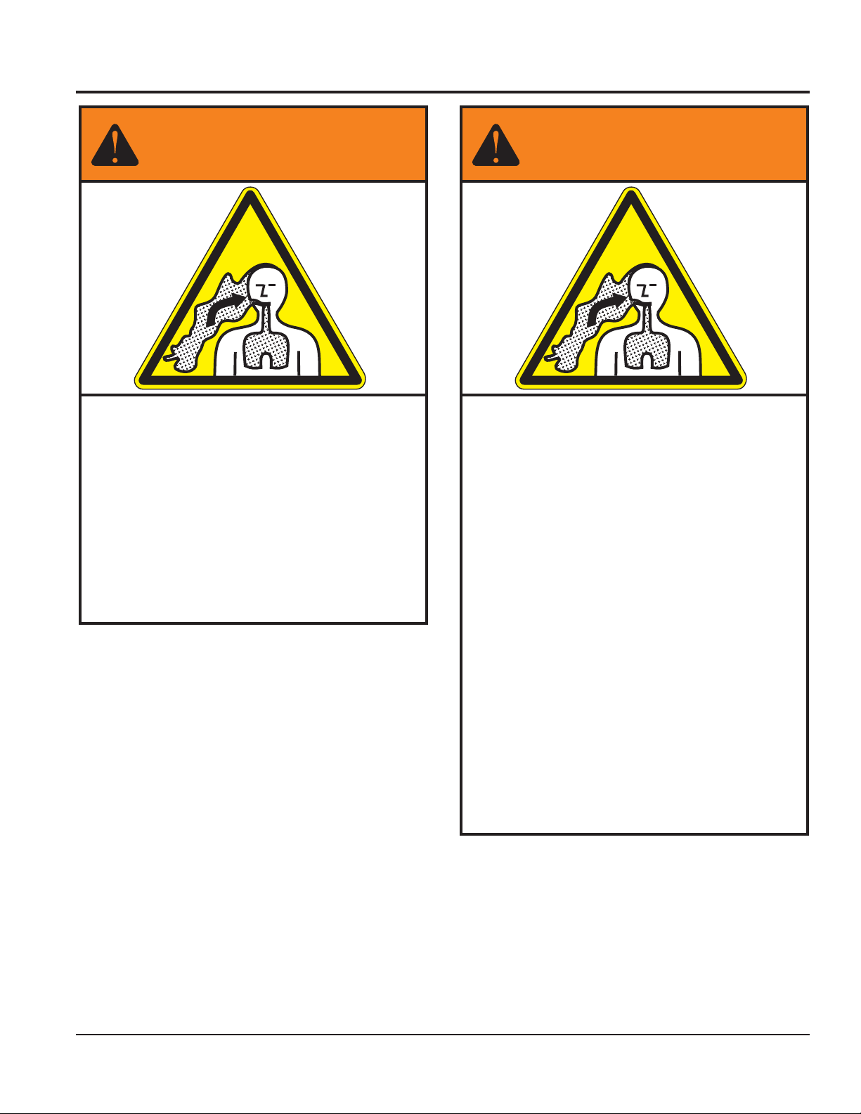
SILICOSIS/RESPIRATORY WARNINGS
WARNING
SILICOSIS WARNING RESPIRATORY HAZARDS
Grinding/cutting/drilling of masonry, concrete, metaland
other materials with silica in their composition may give
off dust or mists containing crystalline silica. Silica is a
basic component of sand, quartz, brick clay, granite and
numerous other minerals and rocks. Repeated and/or
substantial inhalation of airborne crystalline silica can
cause serious or fatal respiratory diseases, including
silicosis. In addition, California and some other
authorities have listed respirable crystalline silica as a
substance known to cause cancer. When cutting such
materials, always follow the respiratory precautions
mentioned above.
WARNING
Grinding/cutting/drilling of masonry, concrete, metaland
other materials can generate dust, mists and fumes
containing chemicals known to cause serious or fatal
injury or illness, such as respiratory disease, cancer,
birth defects or other reproductive harm. If you are
unfamiliar with the risks associated with the particular
process and/or material being cut or the composition of
the tool being used, review the material safety data
sheet and/or consult your employer, the material
manufacturer/supplier, governmental agencies such as
OSHA and NIOSH and other sources on hazardous
materials. California and some other authorities, for
instance, have published lists of substances known to
cause cancer, reproductive toxicity, or other harmful
effects.
Control dust, mist and fumes at the source where
possible. In this regard use good work practices and
follow the recommendations of the manufacturers or
suppliers, OSHA/NIOSH, and occupational and trade
associations. Water should be used for dust
suppression when wet cutting is feasible. When the
hazards from inhalation of dust, mists and fumes cannot
be eliminated, the operator and any bystanders should
always wear a respirator approved by NIOSH/MSHA for
the materials beingused.
WM120PH/SH HYDRAULIC MIXER • OPERATION AND PARTS MANUAL — REV. #7 (09/15/11) — PAGE 3
Page 4
TABLE OF CONTENTS
WM120PH/SH HYDRAULIC
MIXER
Proposition 65 Warning ........................................... 2
Silicosis/Respiratory Warnings ................................ 3
Table of Contents .................................................... 4
Parts Ordering Procedures ..................................... 5
Safety ...................................................................... 6
Safety ...................................................................... 7
Rules and Regulations ....................................... 8-10
Towing Guidelines ................................................. 11
Safety Chain Connection ...................................... 12
Specifications ........................................................ 13
Dimensions ........................................................... 14
General Information .............................................. 15
Mixer Components ........................................... 16-17
Hydraulic Components.......................................... 17
Engine Components ............................................. 18
Electric Motor Components .................................. 19
Paddle Blade Adjustment (Steel Drum) ................ 20
Paddle Blade Adjustment (Poly Drum) .................. 21
Inspection ......................................................... 22-23
Initial Start-Up (Gasoline) ..................................... 24
Initial start-up (Electric) ......................................... 25
Operation ......................................................... 25-26
Shut-Down ............................................................ 27
Maintenance (Engine)...................................... 28-29
Maintenance (Mixer) ........................................ 30-33
Storage ................................................................. 33
Troubleshooting (Engine) ................................. 34-35
Troubleshooting (Mixer/Electric motor) ................. 36
Wiring Diagram (Electric Motor)............................ 37
Hydraulic System Diagram ................................... 38
Explanation of Code in Remarks Column ............. 40
Suggested Spare Parts ......................................... 41
Component DrawingsComponent Drawings
Component Drawings
Component DrawingsComponent Drawings
Hydraulic Assembly .......................................... 54-55
Frame 1 Assembly ........................................... 56-57
Frame 2 Assembly ........................................... 58-59
Frame 3 Assembly ........................................... 60-61
Plastic Engine Cover Assembly ....................... 62-63
Steel Engine Cover Assembly .......................... 64-65
Single Phase, 5 HP Electric Motor Assembly .. 66-67
Three Phase, 5 HP Electric Motor Assembly ... 68-69
HONDA GX390K1QA2/
GX390U1QA2 Engine
Honda Engine Assembly .................................. 70-71
Air Cleaner Assembly....................................... 72-73
Camshaft Assembly ......................................... 74-75
Piston Assembly ............................................... 76-77
Crankcase Cover Assembly ............................. 78-79
Crankshaft Assembly ....................................... 80-81
Cylinder Barrel Assembly ................................. 82-83
Cylinder Head Assembly .................................. 84-85
Fan Cover Assembly ........................................ 86-87
Flywheel Assembly .......................................... 88-89
Ignition Coil Assembly ...................................... 90-91
Carburetor Assembly ....................................... 92-93
Muffler Assembly ............................................. 94-95
Recoil Starter Assembly................................... 96-97
Control Assembly ............................................. 98-99
Fuel Tank Assembly ..................................... 100-101
Gasket Kit Assembly .................................... 102-103
Labels Assembly .......................................... 104-105
Terms and Conditions of Sale — Parts ............... 106
In accordance with our established policy of
constant improvement, we reserve the right to
amend these specifications at any time without
notice.
Nameplate and Decals..................................... 42-43
Paddle Blades Assembly .................................. 44-45
Plastic Mixing Drum Assembly ......................... 46-47
Steel Drum Assembly (Manual) ....................... 48-49
Steel Drum Assembly (Hydraulic) .................... 50-51
Paddle Shaft Assembly (Plastic/Steel) ............. 52-53
PAGE 4 — WM120PH/SH HYDRAULIC MIXER • OPERATION AND PARTS MANUAL — REV. #7 (09/15/11)
Specifications and part numbers are
subject to change without notice.
Page 5
PARTS ORDERING PROCEDURES
r
Ordering parts has never been easier!
Choose from three easy options:
January 1
Effective:
st
, 2006
Best Deal!
Order via Internet
Order parts on-line using Multiquip’s SmartEquip website!
N View Parts Diagrams
N Order Parts
N Print Specification Information
Goto www.multiquip.com and click on
Order Parts
Order via Fax
All customers are welcome to order parts via Fax.
Domestic (US) Customers dial:
1-800-6-PARTS-7 (800-672-7877)
Non-Dealer Customers:
Contact your local Multiquip Dealer for
parts or call 800-427-1244 for help in
locating a dealer near you.
(Dealers Only)
to log in and save!
(Dealers Only)
:
Order via Phone:
If you have an MQ Account, to obtain a Username
and Password, E-mail us at: parts@multiquip.
com.
To obtain an MQ Account, contact you
District Sales Manager for more information.
Use the internet and qualify for a 5% Discount
on Standard orders for all orders which include
complete part numbers.*
Note: Discounts Are Subject To Change
:
Domestic (US) Dealers Call:
1-800-427-1244
Fax your order in and qualify for a 2% Discount
on Standard orders for all orders which include
complete part numbers.*
Note: Discounts Are Subject To Change
International Customers should contact
their local Multiquip Representatives for
Parts Ordering information.
When ordering parts, please supply:
R Dealer Account Number
R Dealer Name and Address
R Shipping Address (if different than billing address)
R Return Fax Number
R Applicable Model Number
R Quantity, Part Number and Description of Each Part
NOTICE
All orders are treated as Standard Orders and will
ship the same day if received prior to 3PM PST.
R Specify Preferred Method of Shipment:
UPS/Fed Ex DHL
N Priority One Tr uck
N Ground
N Next Day
N Second/Third Day
www.multiquip.com
WE ACCEPT ALL MAJOR CREDIT CARDS!
WM120PH/SH HYDRAULIC MIXER • OPERATION AND PARTS MANUAL — REV. #7 (09/15/11) — PAGE 5
Page 6
SAFETY
FOR YOUR SAFETY AND SAFETY OF OTHERS!
Safety precautions should be followed at all
times when operating this equipment. Failure
to read and understand the Safety Messages
and Operating Instructions could result in injury
to yourself and others.
This manual has been developed to
provide complete instructions for the
safe and efficient operation of this
equipment. Refer to the engine
manufacturer's instructions for data
relative to its safe operation.
Before using this equipment ensure that the operating
individual has read and understood all instructions in this
manual.
HAZARD SYMBOLS
Potential hazards associated with the operation of this
equipment will be referenced with Hazard Symbols which
appear throughout this manual, and will be referenced in
conjunction with Safety Message Alert Symbols.
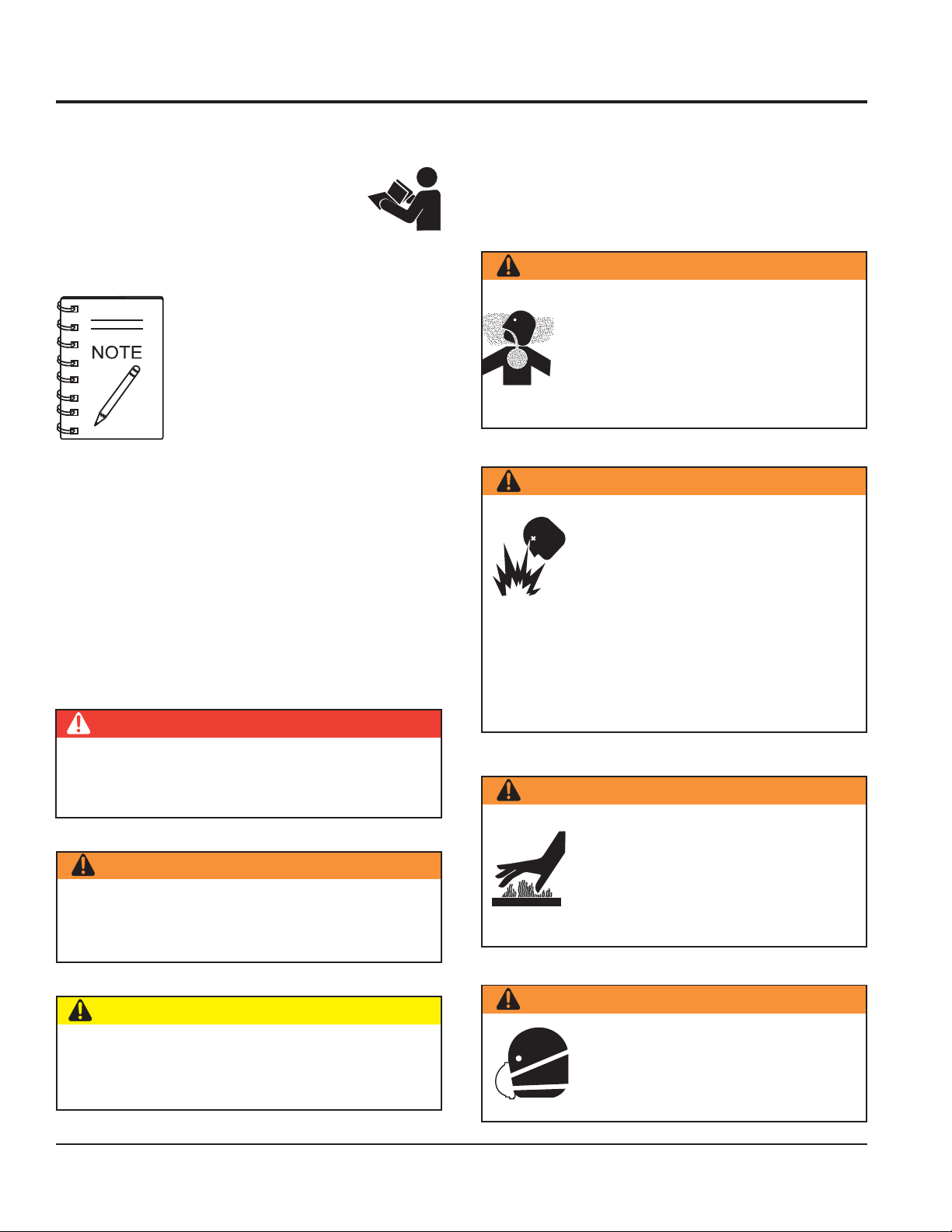
WARNING — Lethal Exhaust Gas Hazards
WARNING — Explosive Fuel Hazards
SAFETY MESSAGE ALERT SYMBOLS
The three Safety Messages shown below will inform you
about potential hazards that could injure you or others. The
Safety Messages specifically address the level of exposure
to the operator, and are preceded by one of three words:
DANGER, WARNING, or CAUTION.
DANGER
is running or hot. DO NOT overfill tank, since spilled
fuel could ignite if it comes into contact with hot engine
parts or sparks from the ignition system. Store fuel in
approved containers, in well-ventilated areas and away
from sparks and flames.
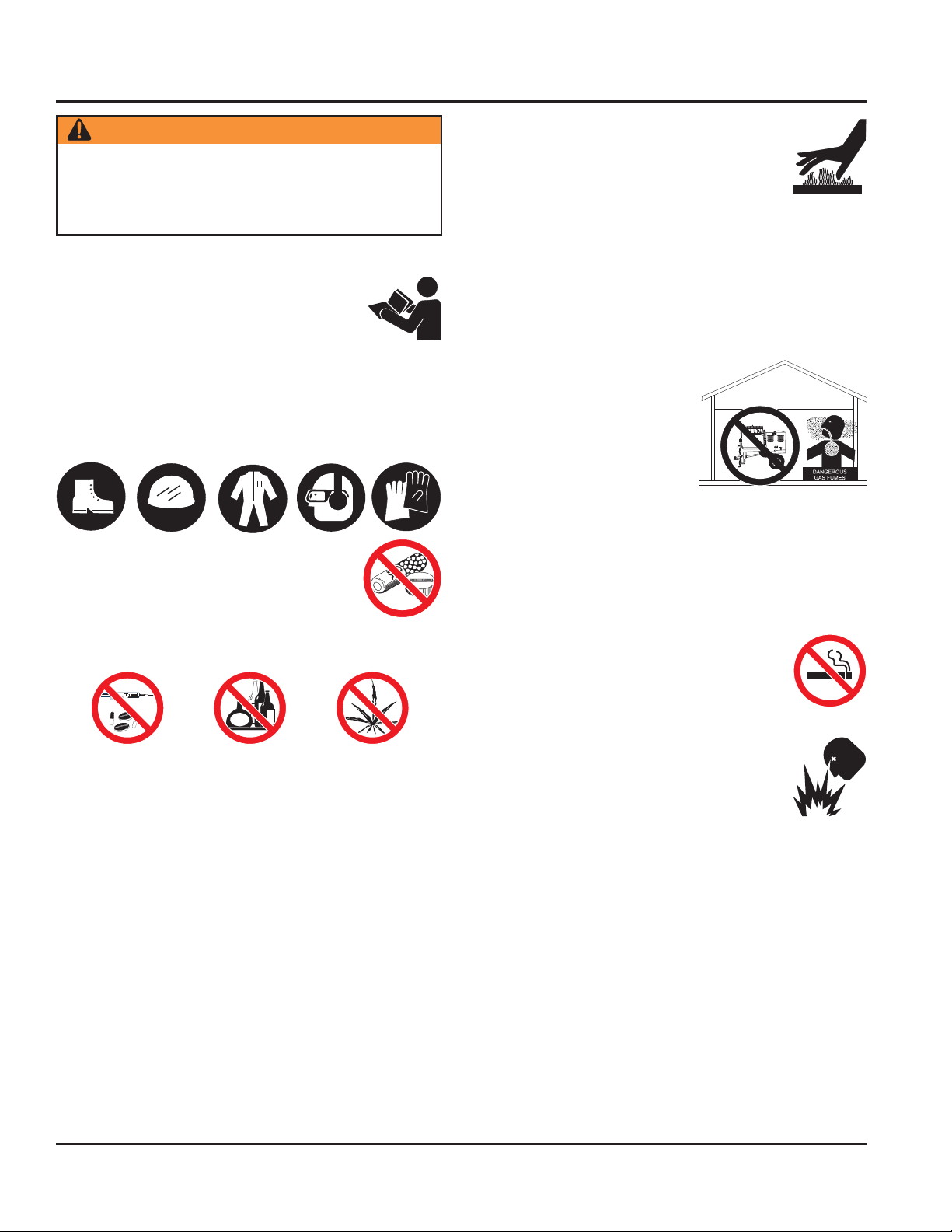
Engine fuel exhaust gases contain poisonous
carbon monoxide. This gas is colorless and
odorless, and can cause death if inhaled.
NEVER operate this equipment in a confined
area or enclosed structure that does not
provide ample free flow air.
Fuel is extremely flammable and its
vapors can cause an explosion if ignited.
DO NOT start the engine near spilled fuel
or combustible fluids.
DO NOT fill the fuel tank while the engine
You WILL be
DO NOT follow these directions.
WARNING
You CAN be KILLED or
DO NOT follow these directions.
CAUTION
You CAN be
directions.
PAGE 6 — WM120PH/SH HYDRAULIC MIXER • OPERATION AND PARTS MANUAL — REV. #7 (09/15/11)
KILLED
or
INJURED
SERIOUSLY INJURED
SERIOUSLY INJURED
if you DO NOT follow these
if you
if you
WARNING — Burn Hazards
Engine components can generate extreme
heat. To prevent burns, DO NOT touch
these areas while the engine is running or
immediately after operation. Never operate
the engine with heat shields or heat guards
removed.
WARNING — Respiratory Hazards
ALWAYS wear approved respiratory
protection when required.
Page 7
SAFETY
CAUTION — Rotating Parts Hazards
NEVER operate equipment with covers or
guards removed. Keep fingers, hands, hair
and clothing away from all moving parts
to prevent injury.
CAUTION — Accidental Starting Hazards
ALWAYS place the equipment ON/OFF
switch in the OFF position when the
equipment is not in use.
CAUTION — Eye and Hearing Hazards
ALWAYS wear approved eye and hearing
protection.
CAUTION — Overspeed Conditions
NEVER tamper with the factory setting of
the engine governor. Personal injury and
equipment damage can result if operating
in speed ranges above the maximum
allowable.
CAUTION — Equipment Damage Hazards
Other important messages are provided throughout this
manual to help prevent damage to your equipment, other
property, or the surrounding environment.
CAUTION — Start/Stop Switch
ALWAYS test the start/stop switch for the gasoline
engine or electric motor every time the engine or electric
motor is started.
WARNING — Stand Clear of Mixer
Always stand clear of the dump handle when the mixer
is in operation. Any binding of material between the mixer
blades and the drum will cause the drum handle to
quickly move and could cause bodily harm.
WM120PH/SH HYDRAULIC MIXER • OPERATION AND PARTS MANUAL — REV. #7 (09/15/11) — PAGE 7
Page 8
WARNING — Read This Manual
Failure to follow instructions in this manual may lead to
serious injury or even
operated by trained and qualified personnel only! This
equipment is for industrial use only.
DEATH
! This equipment is to be
GENERAL SAFETY
DO NOT operate or service this equipment
before reading this entire manual.
This equipment should not be operated by
persons under 18 years of age.
NEVER operate this equipment without proper protective
clothing, shatterproof glasses, steel-toed boots and other
protective devices required by the job.
NEVER operate this equipment when not
feeling well due to fatigue, illness or when
under medication.
NEVER operate this equipment under the
influence of drugs or alcohol.
RULES AND REGULATIONS
NEVER touch the hot exhaust manifold,
muffler or cylinder. Allow these parts to cool
before servicing engine or pump.
ALWAYS allow the engine to cool before
adding fuel or performing service and maintenance
functions. Contact with
serious burns.
NEVER operate this equipment in any enclosed or narrow
area where free flow of the air is restricted. The engine
of this equipment requires an adequate free flow of
cooling air. If the air flow is
restricted it will cause serious
damage to the equipment or
engine and may cause injury
to people and property.
Remember the engine gives
off DEADLY gases.
ALWAYS refuel in a well-ventilated area, away from
sparks and open flames.
ALWAYS use extreme caution when working with
flammable liquids. When refueling, stop the engine and
allow it to cool.
DO NOT smoke around or near the
equipment. Fire or explosion could result
from fuel vapors, or if fuel is spilled on a
hot engine.
hot
components can cause
NEVER operate the equipment in an
NEVER disconnect any
devices"
Disconnection of these devices can cause severe injury,
bodily harm or even death! Disconnection of any of these
devices will void all warranties.
NEVER use accessories or attachments that are not
recommended by Multiquip for this equipment. Damage
to the equipment and/or injury to user may result.
Manufacturer does not assume responsibility for any
accident due to equipment modifications. Unauthorized
equipment modification will void all warranties.
Whenever necessary, replace nameplate, operation and
safety decals when they become difficult read.
ALWAYS check the equipment for loosened threads or
bolts before starting.
. These devices are intended for operator safety.
PAGE 8 — WM120PH/SH HYDRAULIC MIXER • OPERATION AND PARTS MANUAL — REV. #7 (09/15/11)
"emergency or safety
explosive atmosphere or near combustible
materials. An explosion or fire could result
causing severe
bodily harm or even
death.
DO NOT top-off fuel tank. Topping-off is dangerous as it
causes fuel to spill.
ALWAYS store the equipment in a clean, dry location
out of the reach of children.
NEVER run engine without air cleaner or air filter. Severe
engine damage may occur.
NEVER leave the equipment unattended with the engine
running. Turn off engine when unattended.
CAUTION must always be observed while servicing this
equipment. Rotating parts can cause injury if contacted.
Page 9

When towing, an adequate safety chain must be
fastened to the frame. See Towing Guidelines section in
this manual.
Keep all
from the equipment at all times.
Unauthorized equipment modifications will void all
warranties.
Check all fasteners periodically for tightness. Also check
towing tongue bolt, lock nut and wheel lug nuts for wear.
Stop the engine and disconnect the spark plug before
allowing anybody’s hands in the mixing drum.
NEVER pour or spray water over the engine or electric
motor.
When towing, an adequate safety chain must be
fastened to the frame. See Towing Guidelines section in
this manual.
Keep all
from the equipment at all times.
Unauthorized equipment modifications will void all
warranties.
inexperienced
inexperienced
and
and
unauthorized
unauthorized
people away
people away
RULES AND REGULATIONS
WARNING — Manual Dump Drum Handle
Always stand clear of dump handle when equipment is in
operation.
technical questions or information recommended by
Multiquip for this equipment. Damage to the equipment
and/or injury to user may result.
TRANSPORTING
ALWAYS shutdown engine before transporting.
Tighten fuel tank cap securely and close fuel cock to
prevent fuel from spilling.
Drain fuel when transporting equipment over long
distances or bad roads.
MAINTENANCE SAFETY
NEVER lubricate components or attempt service on a
running machine.
ALWAYS allow the machine a proper amount of time to
cool before servicing.
Keep the equipment in proper running condition.
Check all fasteners periodically for tightness. Also check
towing tongue bolt, lock nut and wheel lug nuts for wear.
Stop the engine and disconnect the spark plug before
allowing anybody’s hands in the mixing drum.
NEVER pour or spray water over the engine or electric
motor.
Depending on type of mixer, test the
either the gasoline engine or electric motor before
operating. The purpose of these switches is to shut down
the engine or motor of the mixer
ALWAYS stand clear of the release drum lock. Move
handle downward to empty the drum. Move handle upward
to return to vertical position. Inspect for proper
functionality before starting engine or engaging blades.
Any binding of material between the mixing blades &
drum will cause the handle to quickly rotate if not in the
"up & locked" position.
DO NOT operate this equipment unless all guards and
safety devices are attached and in place.
ON/OFF
switch for
Fix damage to the equipment immediately and always
replace broken parts.
Dispose of hazardous waste properly. Examples of
potentially hazardous waste are used motor oil, fuel and
fuel filters.
DO NOT use food or plastic containers to dispose of
hazardous waste.
DO NOT pour waste, oil or fuel directly onto the ground,
down a drain or into any water source.
Refer to the
WM120PH/SH HYDRAULIC MIXER • OPERATION AND PARTS MANUAL — REV. #7 (09/15/11) — PAGE 9
HONDA Engine Owner's Manual
for engine
Page 10

EMERGENCIES
ALWAYS know the location of the nearest
fire extinguisher
ALWAYS know the location of the nearest
first aid kit
In emergencies,
of the nearest phone or
Also know the phone numbers of the nearest
ambulance, doctor
information will be invaluable in case of emergency.
.
.
always
know the location
keep a phone on the job site
and
fire department
. This
RULES AND REGULATIONS
.
PAGE 10 — WM120PH/SH HYDRAULIC MIXER • OPERATION AND PARTS MANUAL — REV. #7 (09/15/11)
Page 11
TOWING SAFETY PRECAUTIONS
CAUTION — Inspect Towing Components
To reduce the possibility of an accident while transporting
the machine on public roads, always make sure that the
equipment’s towing components and the towing vehicle
are in good operating condition and both units are
mechanically sound. Remember before towing,
local and state laws for proper compliance.
The following list of suggestions should be used when towing
the mixer:
Check with your county or state safety towing regulations
department before towing your
mixer
check with
.
ALWAYS make sure that the fuel valve lever is in the
OFF position (gasoline models only).
Check wheel mounting lug nuts with a torque wrench.
Torque wheel lug nuts as described in the maintenance
section of this manual.
Check tightness of U-clamp nuts, torque suspension
hardware as referenced in the maintenance section of this
manual.
Avoid sudden stops and starts. This can cause skidding,
or jackknifing. Smooth, gradual starts and stops will
improve gas milage.
Avoid sharp turns to prevent rolling.
Tow bar to vehichle connection (Coupler only)
Make sure that the hitch and coupling of the towing
vehicle are rated equal to, or greater than the trailer "gross
vehicle weight rating" (GVWR).
ALWAYS inspect the hitch and coupling for wear. NEVER
tow the mixer with defective hitches, couplings, chains
etc.
CHECK the tire air pressure on both the towing vehicle
and the trailer. Also check the tire tread wear on both
vehicles.
ALWAYS make sure the mixer is equipped with a “Safety
Chain.”
1. Check the vehicle hitch ball, and mixer's coupler for
signs of wear or damage. Replace any parts that are
worn or damaged before towing.
2. Use only a 2-inch ball diameter (towing vehicle), this will
If the mixer tow bar is deformed or damaged, replace
the
tow bar. There exists the possibility of the mixer
separating from the towing vehicle.
TOWING GUIDELINES
CAUTION — Replacing Towing Components
entire
tow bar. NEVER tow the mixer with a defective
ALWAYS attach trailer's safety chain to the frame of
towing vehicle.
ALWAYS make sure that the towing vehicle's directional,
backup, and brake lights are working properly.
Remember in most cases the maximum speed unless
otherwise posted for highway towing is 55 MPH, however
before towing your mixer, check your local state, and
county vehicle towing requirements. Recommended offroad towing is not to exceed 10 or 15 MPH or less
depending on type of terrain.
Place
chocked blocks
rolling,
vehicle.
Inflate tires to correct pressure, inspect tires for cuts, and
excessive wear. See Table 9 (Tire Wear Troubleshooting).
When towing of the mixer is required, place the drum in the
up position (mouth facing upwards) and lock the drum latch.
while parked, if disconnected from towing
WM120PH/SH HYDRAULIC MIXER • OPERATION AND PARTS MANUAL — REV. #7 (09/15/11) — PAGE 11
underneath wheels to prevent
match the mixer's 2-inch coupler. Use of any other ball
diameter will create an extremely dangerous condition which
can result in separation of the coupler and ball or ball
failure.
3. After tow bar has been connected to mixer (see next page),
attach mixer's coupler to the hitch ball on the towing vehicle
securely and make sure the lock lever is in the down
position (locked).
Mixer Tow Bar Vehicle Connection (Pentle and Loop)
1. Make sure the bumper on the towing vehicle is equipped
to handle either a pintle or loop type tow bar configuration.
2. After tow bar has been connected to mixer (see next page),
secure either type of tow bar to the towing vehicle, following
state and county towing regulations.
3. As a minimum, use a 1/2-inch bolt and nylock nut grade 5
when securing the tow bar to the towing vehicle and to
the unit being towed.
Page 12
SAFETY CHAIN CONNECTION
CAUTION — Tow With Safety Chain
NEVER! tow the mixer with the safety chain removed.
The safety chain is intended to prevent complete
separation of the mixer from the towing vehicle in the
event of a tow bar failure.
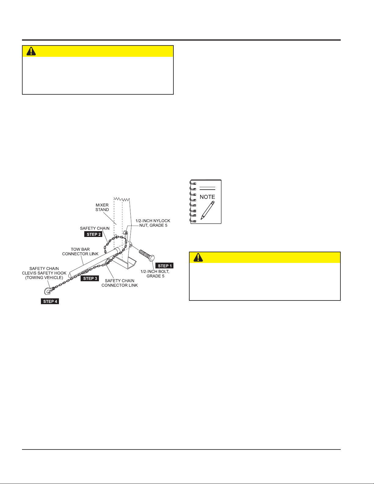
Reference Figure 1 for the installation of the
safety chain
TOW BAR TO MIXER CONNECTION
1. Insert the tow bar through the round opening at the
bottom of the mixer stand.
Align the hole on the tow bar with the hole on the mixer
frame, and insert 1/2-inch bolt through tow bar and
frame. Secure tow bar to frame with 1/2-inch nylock
nut. Tighten to 40 ft.-lbs.
2. Route the safety chain through the holes just above
3. Extend the safety chain along the length of the tow
.
4. Connect the free end of (clevis safety hook) the safety
the tow bar, located on each side of the mixer stand.
Loop the chain together and place under the tow bar.
Secure the loop with the connector link.
bar, looping it through the tow bar's connector link.
Remove any excess chain slack.
chain to the towing vehicle. Remember it is critical that
the length of the chain be properly adjusted, to prevent
the draw bar and the front of the mixer stand from
dropping to the the ground (contact) in the event the
draw bar becomes disconnected from the towing
vehicle.
If a new safety chain is required use P/N 13363.
For a new connector link use P/N 01004.
Figure 1. Tow Bar and Safety Chain Installation
CAUTION — Drum Safety When Towing
DO NOT tow the mixer unless the mixing drum is
completely empty. ALWAYS make sure the drum lock
lever (Figure 24) is in the verticle position (manual dump
mixers only).
PAGE 12 — WM120PH/SH HYDRAULIC MIXER • OPERATION AND PARTS MANUAL — REV. #7 (09/15/11)
Page 13
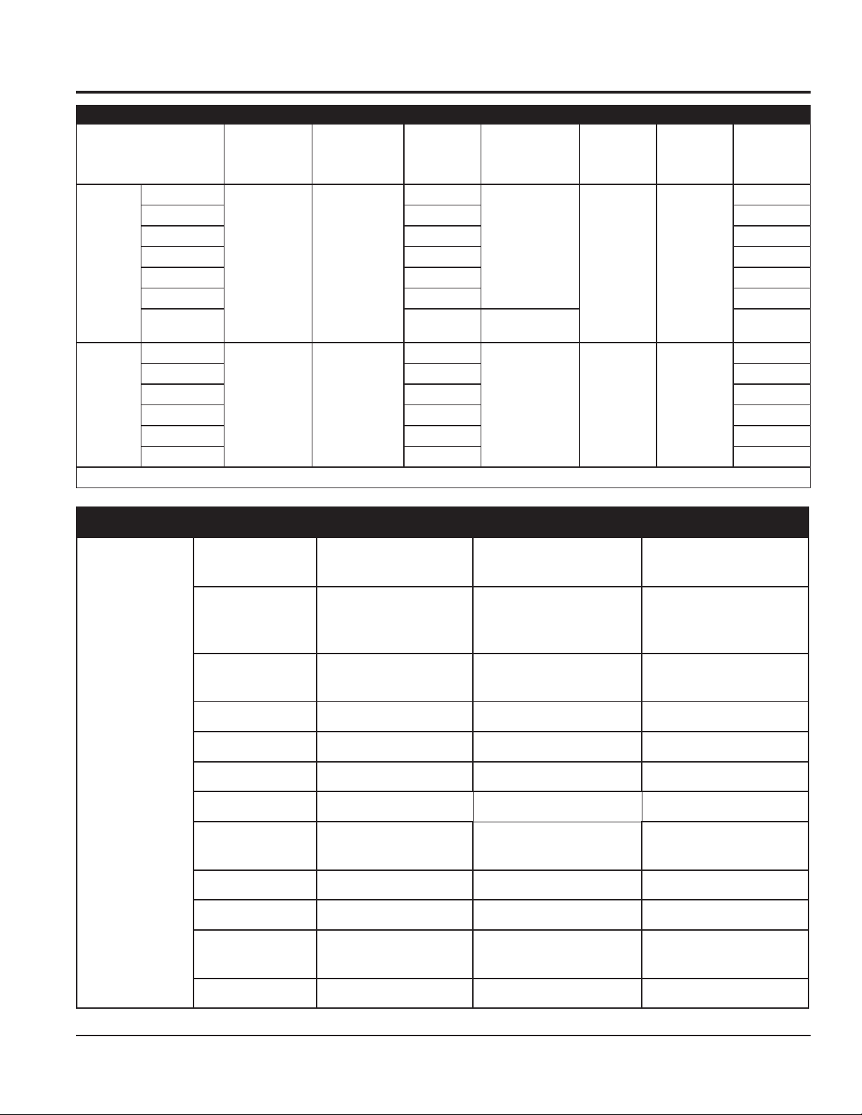
SPECIFICATIONS
rexiMsnoitacificepS1elbaT
ledoMrexiMyticapaCmurD
1ES021MW
D1ES021MW )484(560,1 ciluardyH
3ES021MW )674(050,1 llaunaM
LEETS
CITSALP
D3ES021MW )884(570,1 ciluardyH
HHP021MW )294(580,1 launaM
DHHS021MW )505(011,1 ciluardyH
*SDHHP021MW )534(004,1
1EP021MW
D1EP021MW )184(060,1 ciluardyH
3EP021MW )574(540,1 launaM
D3EP021MW )684(070,1 ciluardyH
HP021MW )184(060,1 lau
DHP021MW )394(580,1 ciluardyH
)sretil(tf.uc
)043(214ot5.3
)043(214ot5.3
yticapaCmurD
).gk24(.sbl49
dnaltroPgaB
tnemeC
)m7.1-4.1(.ni76-45morfelbatsujdasithgieH.sleehwonreximyranoitatS
thgieW
).gk(.sbl
4(040,1
)27
)964(530,1
).mc(.niHxWxL
26x65x48
)751x241x312(
26x65x48
)751x241x312(
95x78
*)241x122(
egrahcsiD
thgieH
).mc(.ni
potSmorF
)64(81ciluardyH
)64(81ciluardyH
evirDnoitcApmuD
launaM
ciluardyH
M
launa
naM
)ROTOMCIRTCELE/ENIGNE(SNOITACIFICEPS.2ELBAT
ledoM
epyT
ekortSXeroB
tnemecalpsiD)ni-uc7.32
/2AQ1K093XGADNOH
2AQ1U093XG
,ekorts4delooc-riA
latnoziroH
enignEenilosaGtfahS
.ni15.2X.ni64.3
)mm46xmm88(
(.cc983A/NA/N
ODLABM4363RODLAB
CL6463R
elgniS,CAV032,PH5
rotoMcirtcelEesahP
A/NA/N
eerhT,CAV064/032,PH5
rotoMcirtcelEesahP
tuptuOxaMM.P.R0063/PH0.11MPR5271/.P.H0.5MPR0571/.P.H0.5
cirtcelE/enignE
rotoM
daoLlluFA/N327.6/4.31
tuptuOsuounitnoCM.P.R0063/PH0.9A/NA/N
spmA
knaTleuF
yticapaC
.slagSU7.1
)sretil5.6(
A/NA/N
leuFenilosaGdedaelnUA/NA/N
yticapaCliOebuL)sre
til1.1(stq61.1A/NA/N
lortnoCdeepS
dohteM
epyT
thgiew-ylFlagufirtneC
A/NA/N
dohteMgnitratStratSlioceRA/NA/N
WM120PH/SH HYDRAULIC MIXER • OPERATION AND PARTS MANUAL — REV. #7 (09/15/11) — PAGE 13
Page 14
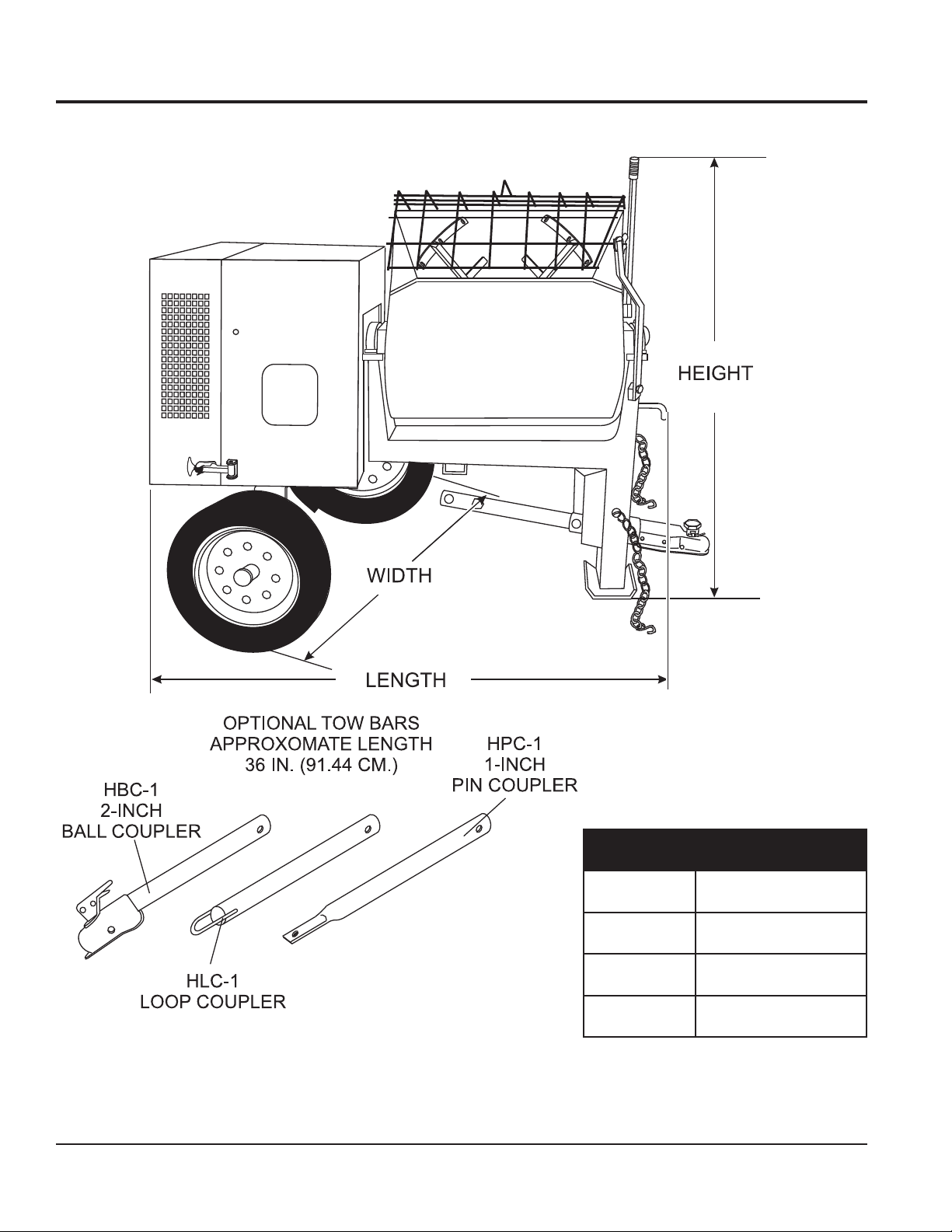
DIMENSIONS
snoisnemiD.3elbaT
noitpircseD).mc(.nisnoisnemiD
htgneL).mc312(.ni48
htdiW).mc241(.ni65
thgieH).mc751(.ni26
PAGE 14 — WM120PH/SH HYDRAULIC MIXER • OPERATION AND PARTS MANUAL — REV. #7 (09/15/11)
Figure 2. Dimensions
Page 15

GENERAL INFORMATION
Application
The MQ WM120 series hydraulic mixers (drum capacity
12.0 cu. ft./340 liters) are shipped completely assembled
and have been factory tested and are ready for use.
Hardware
Check all hardware on the mixer before starting. Periodically
inspect all hardware. Loose hardware can contribute to early
component failure and poor performance. Use Table 4 as
general guideline when torqueing of mixer hardware is
This mixer is only intended for the mixing of plaster and
mortar. The mixer must be used for its intended purpose
required. Remember to keep all mixer hardware components
tight.
and is not suitable for the mixing of flammable or explosive
substances. The mixer must not be used in an explosive
atmosphere. This mixer has a batch capacity between 3-1/
2 and 4-1/2 bags.
Power Plants
Engine Maintenance
For basic engine maintenance, refer to the engine
maintenance section in this manual. For a more detailed
engine maintenance, refer to the
manual furnished with the engine.
These hydraulic mixers can be powered by either a 11 HP
Honda GX390 air-cooled, 4-stroke gasoline engine or a 5.0
HP electric motor. Refer to Table 2 for specific engine or
electric motor data information.
Electrical
If mixer is equipped with an
that the power being supplied to the motor corresponds to
the voltage rating label on the motor. Supplying the wrong
voltage to the electric motor will cause severe electrical
damage to the motor.
Always make sure the
OFF/ON
is in the OFF position before applying power.
electric motor
, make sure
switch on the electric motor
Honda
noitadnemmoceR s
erawdraH
retemaiD
81xhcni-61/541
61xhcni-8/342
373
42xhcni-8/
31xhcni-2/193
31xhcni-2/1
)8edarG(
Engine Owner's
euqroTerawdraH.4elbaT
)sbl-tf(euqroT
09
Extension Cables
The extension cable should be a 3-wire configuration that
includes a ground wire that conforms to UL code. The wire
cross section must be a minimum of 2.5 mm
extension cord of adequate current carrying capacity as
referenced in Table 5. Remember
cable distance
the current-voltage capacity of the extension cable.
Ensure that the extension cable is carefully laid out avoiding
wet areas, sharp edges
and locations where vehicles might
run over it. Avoid allowing the extension cable to be trapped
underneath the mixer.
Unroll the extension cable fully or it will overheat and could
catch fire. Make sure that all extension cable connections
are dry and safe. Replace any defective or badly worn
extension cable immediately.
WM120PH/SH HYDRAULIC MIXER • OPERATION AND PARTS MANUAL — REV. #7 (09/15/11) — PAGE 15
2
. Choose an
affects
Page 16
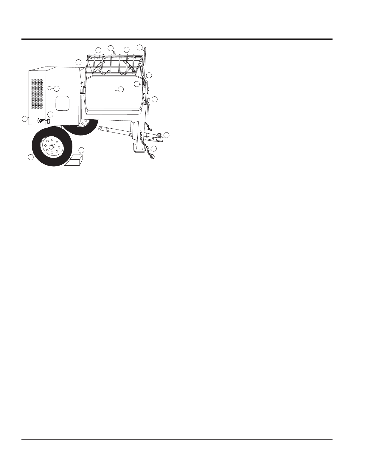
MIXER COMPONENTS
7
6
9
8
9. Manual Dump Handle — Pull this handle downward
to dump the contents of the drum. Push the handle
5
10
3
11
13
12
upward to return the drum to its vertical position. This
feature is not available on hydraulic dump models.
10. Safety Grill Lock Handle — To prevent injury to hands
and arms, the safety grill should ALWAYS be locked
when the mixing of plaster or mortar is required. Also
when transporting the mixer the safety grill should be
2
4
locked. The safety grill should only be un-locked when
cleaning of the blades and drum is required.
14
16
1
15
11. Pivot Point/Zerk Fitting — There is a zerk grease
fitting on each end of the mixing drum. These fittings
lubricate the dumping mechanism. Lubricate both
fittings at least twice a week.
12. Drum Lock Lever — Rotate this lever horizontally to
Figure 3. Mixer Components (Wheels)
Figures 3 and 4 illustrate the basic components and controls
of the WM120 series hydraulic mixer
1. Tires — Replace with manufacturer recommeded tires
only. This mixer requires 13-inch 4-ply tires.
2. Engine Cover — Lift this cover to gain access to the
engine or electric motor.
3. ON/OFF Switch (gasoline) — This switch is provided
on
mixers with gasoline
engines only and is located
on the side of the engine cover. When activated it will
shut down the engine.
4. Latch — Use this latch to secure the engine/electric
motor compartment enclosure.
5. Drum Bearing — There is a sealed bearing on each
end of the mixing drum. Bearings are packed and sealed
at the factory and require no further maintenance.
lock the drum for mixing. Rotate vertically to release
the drum for dumping. This feature is not available on
hydraulic dump models.
13. Mixing Drum — Mixing drums are available in two
types of materials plastic and steel. Drum capacity is
12 cu. ft (340 liters). Mixing materials such as mortar,
plaster are to be placed into this drum for mixing.
Always clean drum after each use.
14. Tow Bar/Coupler — This mixer uses a 2-inch coupler
or pintle towbar.
15. Safety Chain — This mixer uses a 3/16-inch thick,
72-inches long zinc-plated saftey chain.
connect the safety chain when towing.
16. Chock Blocks — Place these blocks (not included as
part of the mixer package) under each mixer wheel to
prevent rolling.
ALWAYS
6. Mixing Paddles — This mixer uses plastic and rubber
mixing paddles for the mixing of plaster and mortar.
Always clean paddles after each use.
7. Bag Cutter — This feature allows mixing bags to be
opened easily, therefore allowing the contents of the
bag to fall directly into the mixing drum.
8. Safety Grill — Provided for operator safety. This safety
grill is designed to keep hands and solid objects out of
the mixing drum when in use. This grill should be closed
at all times when mixer is in use. DO NOT remove the
grill or grill opening bar. Keep the grill clean by washing
it down daily.
PAGE 16 — WM120PH/SH HYDRAULIC MIXER • OPERATION AND PARTS MANUAL — REV. #7 (09/15/11)
Page 17
MIXER COMPONENTS/HYDRAULIC COMPONENTS
17
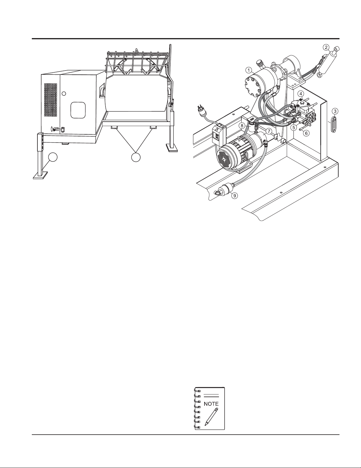
Figure 4. Mixer Components (Stationary)
18
17. Adjustable Stabilizer Jack Stands — Use these jack
stands (3) to adjust the mixer to the desired height.
18. Forklift Pockets — When lifting of the mixer is required,
use these fork lift pockets to lift the mixer. Remember
to insert the forks of the forklift a minimum of 24 inches
into the lift pockets.This feature is only available on
the stationary mixer model.
5. Hydraulic Dump Lever — This lever is provided on
mixers with
HYDRAULIC COMPONENTS
Figure 5 illustrates the hydraulic components used on the
mixer.
1. Hydraulic Motor — Bi-directional hydraulic motor that
is used in conjunction with the directional control valve
to operate the hydraulic dump cylinder and paddle shaft.
2. Hydraulic Dump Cylinder — When activated, this
cylinder will cause the mixing drum to rotate to the
dump position.This cylinder is provided only on mixers
with
hydraulic dump
capability only.
outward to activate dump cylinder.
6. Hydraulic Paddle Blade Lever — 3-position lever.
Push inward for clockwise mixing rotation of blades.
Place in center position for no rotation (neutral/off).
7. Pump — Supplies hydraulic fluid to the hydraulic
control valve.
8. Hydraulic Oil Filter — 10 micron hydraulic filter. Filters
out small particles that are harmful to the hydraulic
system.
9. Strainer — Filters out large particles and debris that
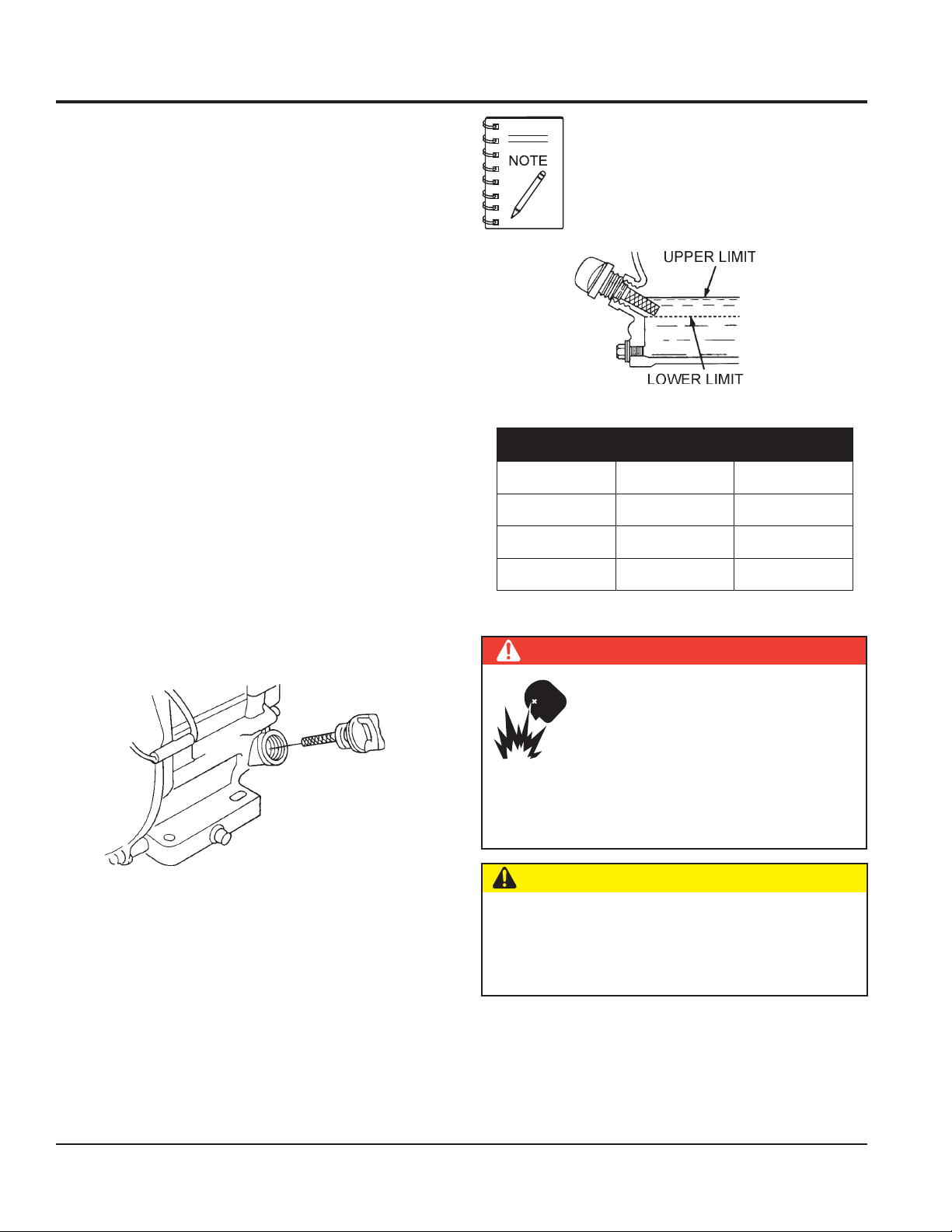
3. Hydraulic Oil Sight Gauge — This gauge indicates
are harmful to the hydraulic system.
the level and temperature of the hydraulic oil. For normal
operation oil level should be visible at the midpoint on
the sightglass.
Figure 5. Hydraulic Components
hydraulic dump
capability only. Pull lever
4. Hydraulic Valve — Directional hydraulic control valve.
Controls the direction of hydraulic fluid supplied to the
dump cylinder and paddle shaft.
Figure 5 shows configuration for electric motor.
Gasoline engine is configured in the same
manner.
WM120PH/SH HYDRAULIC MIXER • OPERATION AND PARTS MANUAL — REV. #7 (09/15/11) — PAGE 17
Page 18
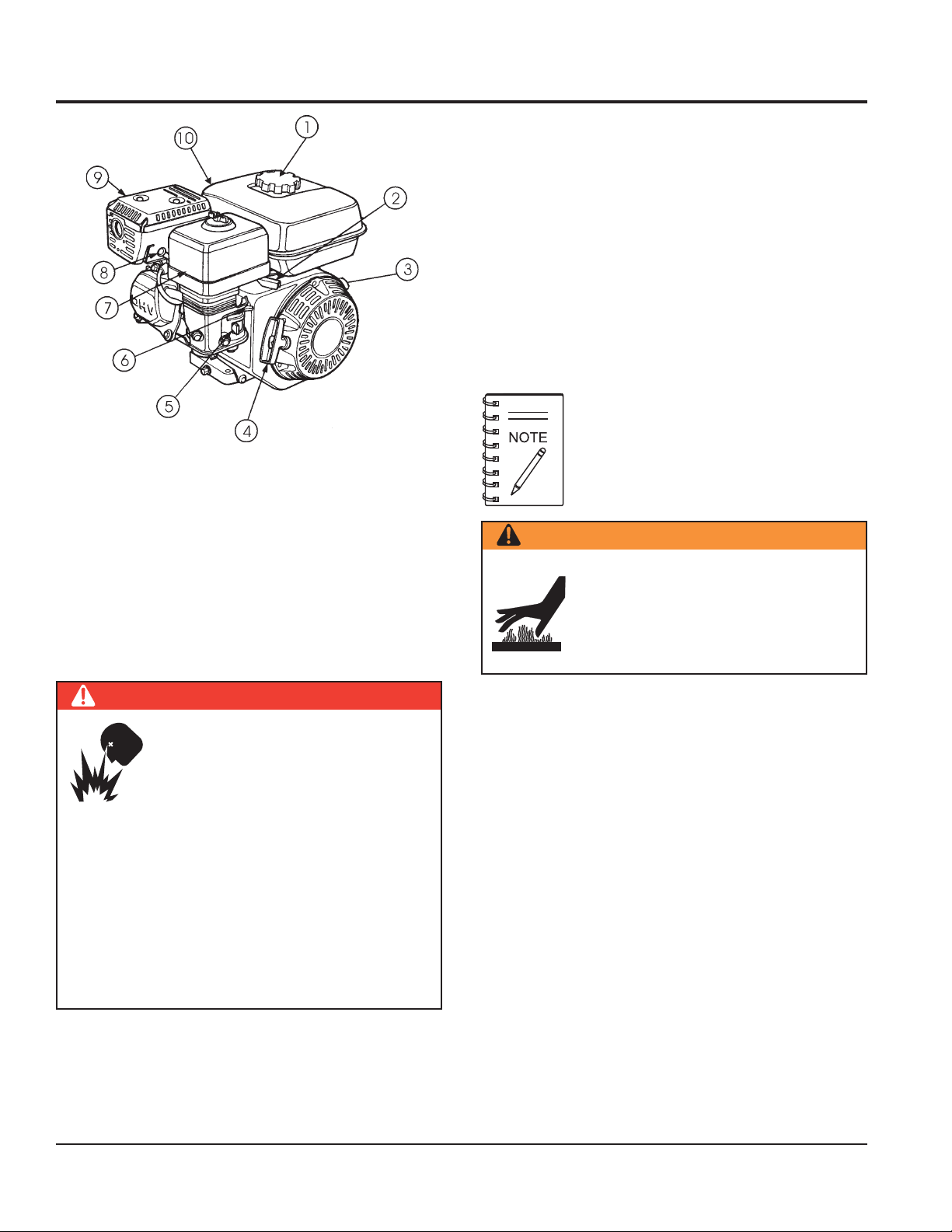
Figure 6. Engine Controls and Components
INITIAL SERVICING
ENGINE COMPONENTS
4. Recoil Starter (pull rope) – Manual-starting method.
Pull the starter grip until resistance is felt, then pull
briskly and smoothly.
5. Fuel Valve Lever – OPEN to let fuel flow, CLOSE to
stop the flow of fuel.
6. Choke Lever – Used in the starting of a cold engine,
or in cold weather conditions. The choke enriches the
fuel mixture.
7. Air Cleaner – Prevents dirt and other debris from
entering the fuel system. Remove wing-nut on top of
air filter cannister to gain access to filter element.
Operating the engine without an air filter, with
a damaged air filter, or a filter in need of
replacement will allow dirt to enter the
engine, causing rapid engine wear.
The engine (Figure 6) must be checked for proper lubrication
and filled with fuel prior to operation. Refer to the
manufacturers engine manual for instructions & details of
operation and servicing.
1. Fuel Filler Cap – Remove this cap to add unleaded
gasoline to the fuel tank. Make sure cap is tightened
securely. DO NOT over fill.
DANGER — Explosive Fuel Hazards
Fuel is extremely flammable and its
vapors can cause an explosion if ignited.
DO NOT start the engine near spilled fuel
or combustible fluids. In the event of a
fuel spill, wait until the fuel residue has
been completely wiped up and the area surrounding the
engine is dry before starting the engine.
DO NOT fill the fuel tank while the engine is running or
hot. DO NOT overfill tank, since spilled fuel could ignite
if it comes into contact with hot engine parts or sparks
from the ignition system. Store fuel in approved
containers, in well-ventilated areas and away from
sparks and flames.
WARNING — Burn Hazards
8. Spark Plug – Provides spark to the ignition system.
Set spark plug gap to 0.6 - 0.7 mm (0.028 - 0.031 inch)
Clean spark plug once a week.
9. Muffler – Used to reduce noise and emissions.
10. Fuel Tank – Holds unleaded gasoline. Fuel tank
capacity is 1.7 gallons (6.5 liters) For additional
information refer to engine owner's manual.
Engine components can generate extreme
heat. To prevent burns, DO NOT touch
these areas while the engine is running or
immediately after operation. Never operate
the engine with the muffler removed.
2. Throttle Lever – Used to adjust engine RPM speed
(lever advanced forward
operator
3. Engine ON/OFF Switch – ON position permits engine
starting, OFF position stops engine operations.
PAGE 18 — WM120PH/SH HYDRAULIC MIXER • OPERATION AND PARTS MANUAL — REV. #7 (09/15/11)
FAST
).
SLOW
, lever back toward
Page 19
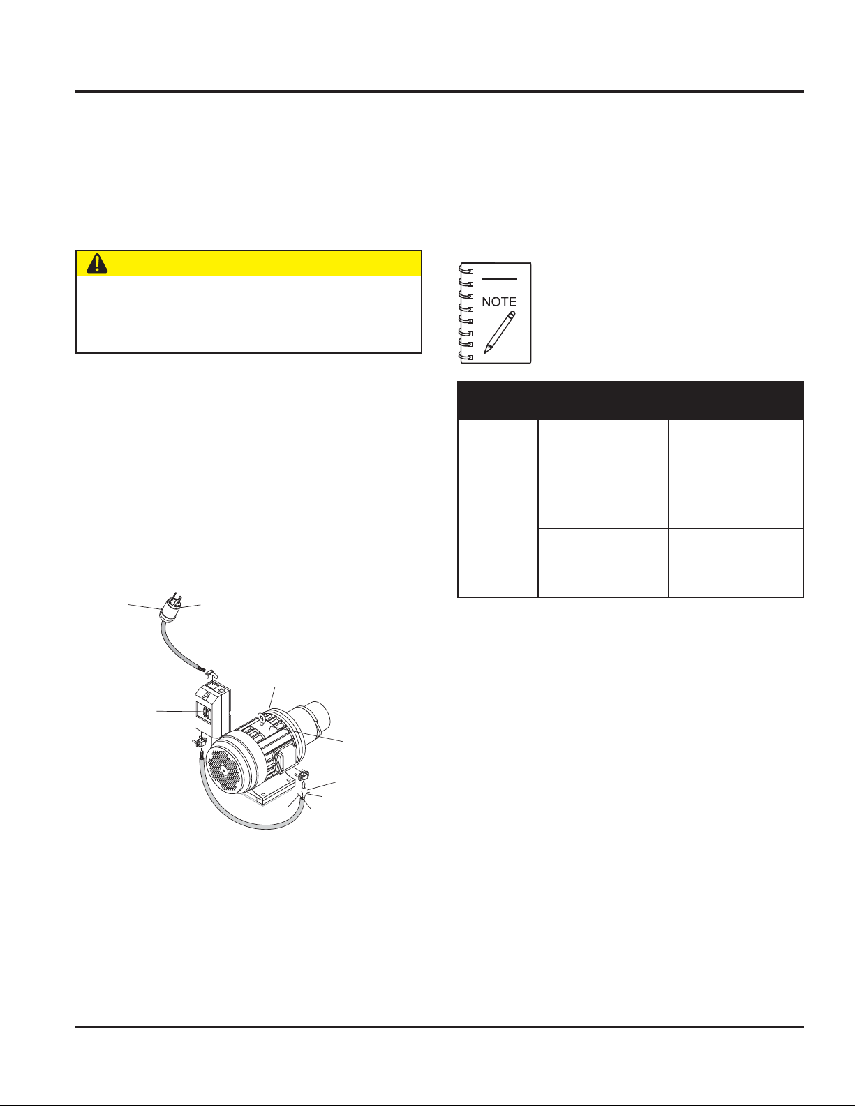
ELECTRIC MOTOR COMPONENTS
ELECTRIC MOTOR
For lubrication care and operation of the electric motor,
refer to your electric motor instruction booklet furnished
with the motor.
Protect the electric motor from dust as much as possible
Electric Motor Connection
The electrical motors used on these mixers are equipped
with either a 3-prong (1Ø) or a 4-prong (3Ø) plug (Figure 7)
for connection to a power source. Reference Table 5. to
determine the required NEMA mating receptacle.
and keep ventilating openings clean.
CAUTION
DO NOT spray water at any time on the electric motor.
DO NOT operate electric motor in an explosive
environment.
The electric motors (Figure 7) used on these mixers is
available in two types of configurations, 5 HP 1Ø @230
VAC or 5 HP 3Ø @230/460 VAC. Pay special attention to
the nameplate on the electric motor when supplying power
to the electric motor. Applying incorrect power to the motor
can severly damage the motor and may cause serious
bodily injury!
Always make certain that the correct voltage is being
supplied to the motor. The input voltage requirements can
be found on the electric motor's nameplate.
NEMA
L6 30P PLUG
230 VAC
1Ø PHASE
NEMA
L16 20P PLUG
230/460 VAC
3Ø PHASE
It is strongly recommended that all electrical
wiring be done by a
licensed electrician
special attention to the nameplate on the electric
motor. Make certain that the voltage supplied to
the electric motor matches the required
operating voltage printed on the nameplate.
noitamrofnIgniriWrotoMcirtcelE.5elbaT
rotoMcirtcelE
rewopesroH
gnitaR
PH5
noC
esahPØ1-CAV032esahPØ3-CAV064/032
r
otcennoCgulPAMEN
gnorP-3
497102N/PP03-6L
elcatpeceRAMEN
rotcen
gnorP-3
DBTN/PR03-6L
gnorP-4
rotcennoC
gnorP-4
. Pay
rotcennoCgulPAMEN
023210111N/PP02-61L
elcatpeceRAMEN
043210011N/PR02-61L
SINGLE OR THREE PHASE
ELECTRIC MOTOR
ON/OFF
SWITCH
NAMEPLATE
PIGTAIL END
ELECTRIC CABLE
BLACK
WHITE
GREEN
Figure 7. Electric Motor
WM120PH/SH HYDRAULIC MIXER • OPERATION AND PARTS MANUAL — REV. #7 (09/15/11) — PAGE 19
Page 20
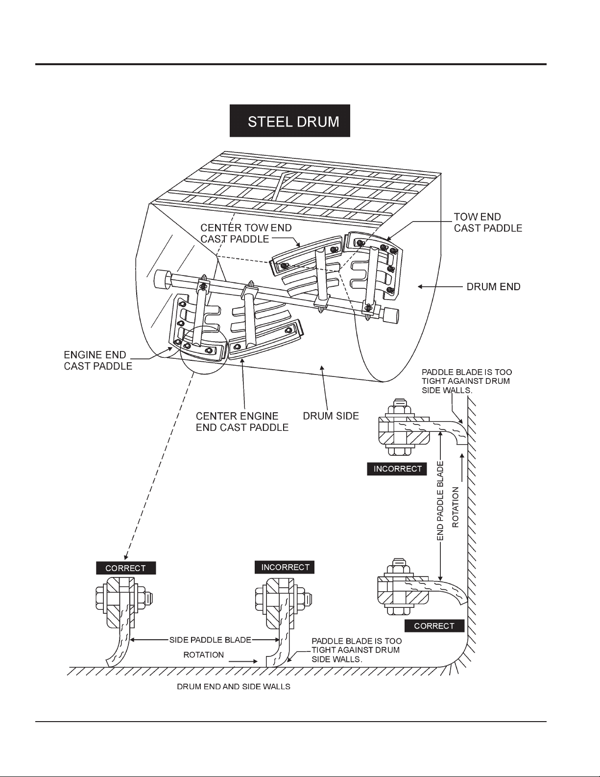
PADDLE BLADE ADJUSTMENT (STEEL DRUM)
Adjust paddles as shown in Figure 8.
Figure 8. Paddle Blade Adjustment (Steel Drum)
PAGE 20 — WM120PH/SH HYDRAULIC MIXER • OPERATION AND PARTS MANUAL — REV. #7 (09/15/11)
Page 21
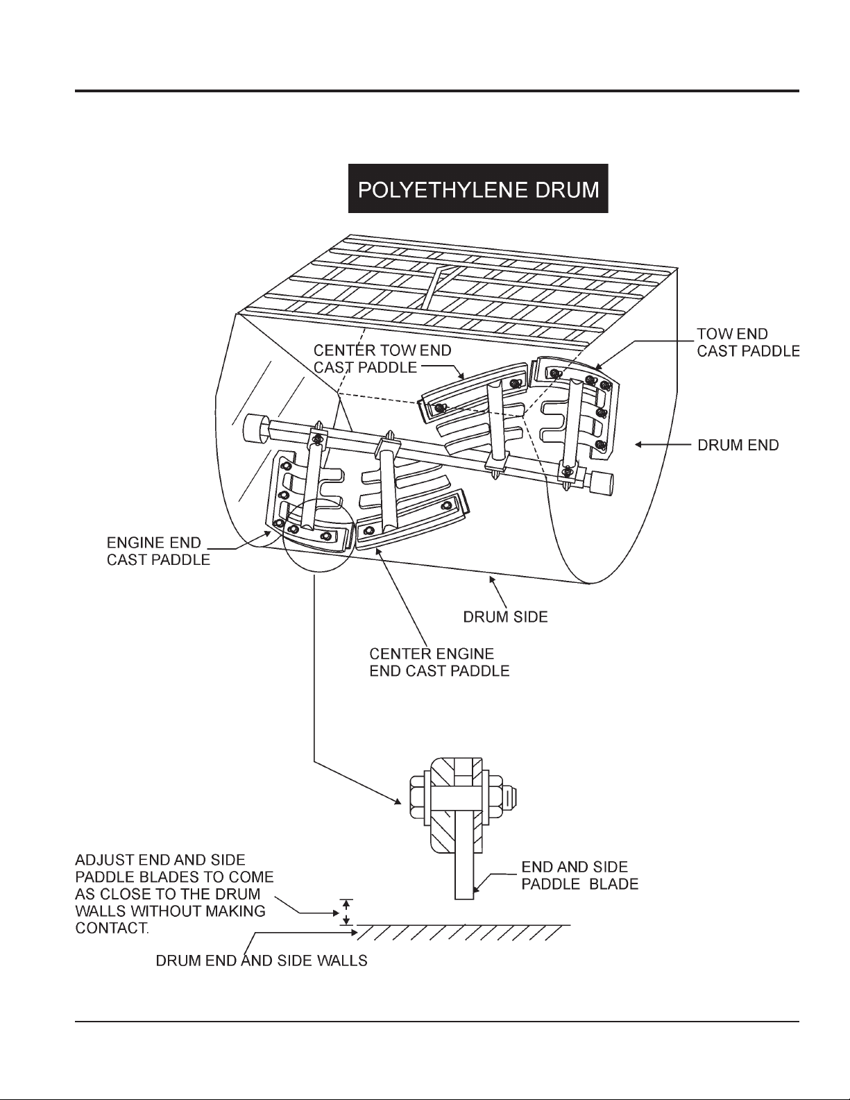
PADDLE BLADE ADJUSTMENT (POLY DRUM)
Adjust paddles as shown in Figure 9.
Figure 9. Paddle Blade Adjustment (Poly Drum)
WM120PH/SH HYDRAULIC MIXER • OPERATION AND PARTS MANUAL — REV. #7 (09/15/11) — PAGE 21
Page 22
This section is intended to assist the operator with the
inspection of the hydraulic mixer. It is extremely important
that this section be read carefully before attempting to use
the mixer in the field.
DO NOT use your mixer until this section is thoroughly
understood.
BEFORE STARTING
INSPECTION
Reference manufacturer engine manual for
specific servicing instructions.
1. Read
all safety instructions
at the beginning of
manual.
2. Clean the
mixer
, removing dirt and dust, particularly
the engine cooling air inlet, carburetor and air cleaner.
3. Check the air filter for dirt and dust. If air filter is
dirty, replace air filter with a new one as required.
4. Check carburetor for external dirt and dust. Clean with
dry compressed air.
5. Check fastening nuts and bolts for tightness.
ENGINE OIL CHECK
1. To check the engine oil level, place the mixer on secure
level ground with the engine stopped.
2. Remove the filler dipstick from the engine oil filler hole
(Figure 10) and wipe it clean.
FUEL CHECK
DANGER — Explosive Fuel Hazards
mishandled. DO NOT smoke while refueling. DO NOT
attempt to refuel the mixer if the engine is hot! or
running.
Figure 11. Engine Oil Dipstick (Removal)
EPYTLIO.6ELBAT
nosaeS erutarepmeT epyTliO
remmuS rehgiHroC°52 03-W01EAS
llaF/gnirpS C°01~C°52 02/03-W01EAS
retniW rewoLroC°0 01-W01EAS
If your mixer has a gasoline engine,
determine if the engine fuel is low. If fuel
is low, remove the fuel filler cap and fill it
with unleaded gasoline. Motor fuels are
highly flammable and can be dangerous if
Figure 10. Engine Oil Dipstick (Removal)
3. Insert and remove the dipstick without screwing it into
the filler neck. Check the oil level shown on the dipstick.
CAUTION — Start/Stop Switch
NEVER! disable or disconnect the start/stop switch. It
is provided for operator safety. Injury may result if it is
disabled, disconnected or improperly maintained.
4. If the oil level is low (Figure 11), fill to the edge of the
oil filler hole with the recommended oil type (Table 6).
Maximum oil capacity is 1.16 quarts (1.1 liters).
1. Remove the gasoline cap located on top of fuel tank.
2. Visually inspect to see if fuel level is low. If fuel is low,
replenish with
unleaded
fuel.
3. When refueling, be sure to use a strainer for filtration.
DO NOT top-off fuel. Wipe up any spilled fuel.
PAGE 22 — WM120PH/SH HYDRAULIC MIXER • OPERATION AND PARTS MANUAL — REV. #7 (09/15/11)
Page 23
HYDRAULIC OIL
Check hydraulic oil sight gauge (Figure 12) to ensure that
hydraulic oil is at the midway level.
Figure 12. Hydraulic Oil Sight Gauge
INSPECTION
HYDRAULIC HOSES
Check hydraulic hoses to make sure they are not worn,
frayed or defective.
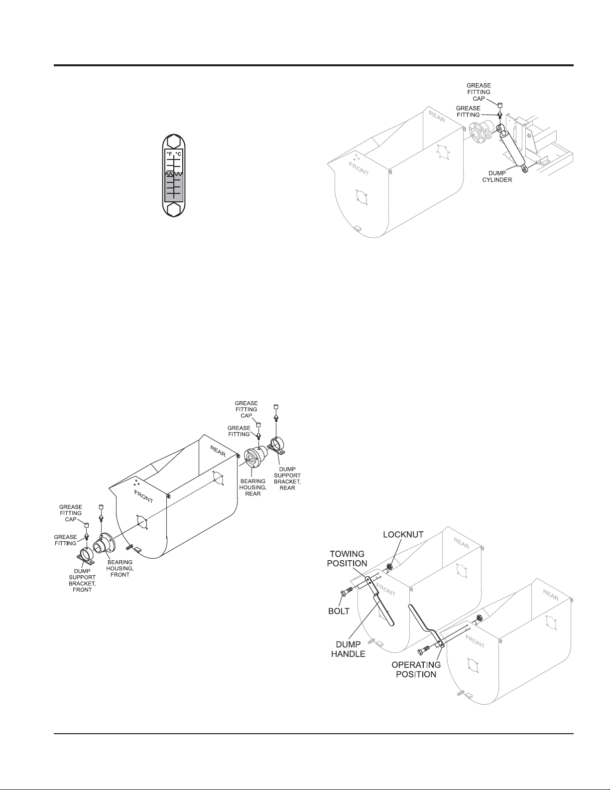
GREASE FITTINGS (BEARINGS)
Check the zerk grease fittings (Figure 13) on the bearing
housings and dump support brackets at each end of the
mixing drum. These grease fittings lubricate the dumping
mechanism. If the dumping handle is stiff or hard to move
lubricate these fittings.
Figure 14. Grease Fittings (Dump Cylinder)
BLADE CHECK
Check for worn or paddle blades. Make sure that all blades
are adjusted properly. See blade adjustment procedure in
this manual. Replace all defective or damaged blades
immediately.
DUMP HANDLE (MANUAL DUMP MACHINES ONLY)
Before operating a manual dump mixer, ensure that the
dump handle has been placed in the operating position.
See Figure 15.
1. Remove and retain nuts (2) and bolts (2) that secure
dump handle to the drum in towing position.
2. Place dump handle in operating position and re-install
nuts and bolts to secure dump handle to drum.
Figure 13. Grease Fittings (Bearings)
GREASE FITTING (DUMP CYLINDER)
1. If your unit has hydraulic dump capability, check the
zerk grease fitting at the top of the dump cylinder
(Figure 14). This grease fitting lubricates the hydraulic
dumping mechanism.
Figure 15. Dump Handle
WM120PH/SH HYDRAULIC MIXER • OPERATION AND PARTS MANUAL — REV. #7 (09/15/11) — PAGE 23
Page 24

INITIAL START-UP (GASOLINE)
STARTING THE ENGINE
4. Place the engine ON/OFF switch (Figure 19) in the ON
The following steps outline the procedure for starting the
engine. Depending on the type of engine employed in the
mixer the steps may vary slightly. If your mixer has an
electric motor disregard this section.
1. Place the fuel valve lever (Figure 16) in the ON position.
5. Located on the engine cover is the
switch (Figure 20). Pull this switch outward to start the
engine.
Figure 16. Fuel Shut-OFF Lever
2. To start a cold engine, move the choke lever (Figure
17) to the CLOSED position.
position position.
Figure 19. Engine ON/OFF Switch
engine start/stop
START STOP
SWITCH
PULL OUT
TO START
PUSH
TO STOP
Figure 20. Main ON/OFF Switch
6. Pull the
starter grip
(Figure 21) lightly until you feel
resistance, then pull briskly. Return the starter grip
gently. Push the clutch lever forward, toward the tow
Figure 17. Choke Lever
tongue end of the mixer. When engine starts, adjust
throttle lever so that paddle shaft inside mixer rotates
3. Move the throttle lever (Figure 18) away from the slow
position, about 1/3 of the way toward the fast position.
Figure 18. Throttle lever Lever
between 30-40 RPMs. The number of RPMs will vary
depending on engine type and load.
Figure 21. Starter Grip
PAGE 24 — WM120PH/SH HYDRAULIC MIXER • OPERATION AND PARTS MANUAL — REV. #7 (09/15/11)
Page 25
INITIAL START-UP (ELECTRIC)/OPERATION
STARTING THE ELECTRIC MOTOR
1. Using an adequate size extension cord (Table 7),
connect one end of the extension cord to the plug on
the electric motor, connect the other end to the power
source. Make sure the motor is configured for the
proper operating voltage.
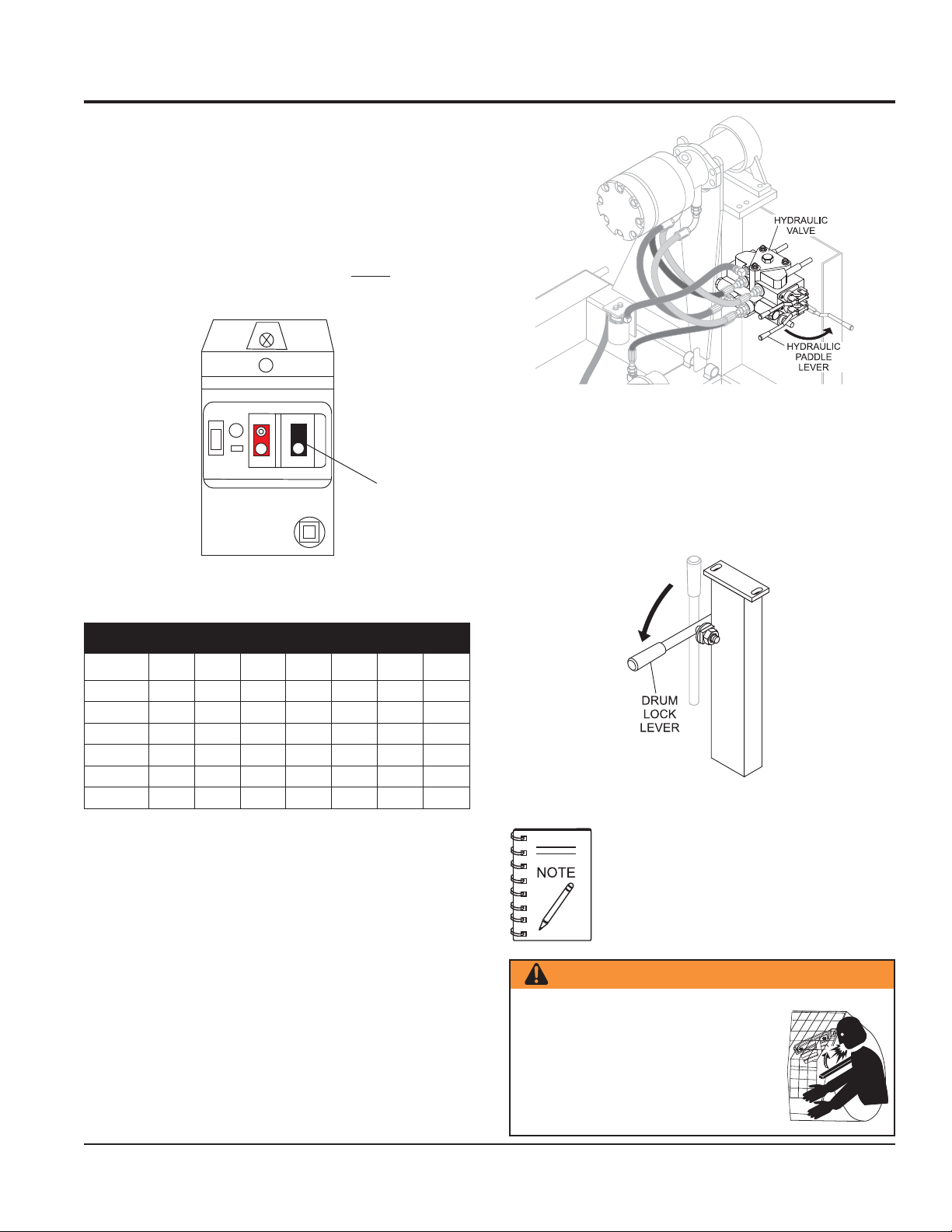
2. To start the electric motor, press the
black
ON/START
switch (Figure 22).
ON
OFF
STOP
START
PRESS TO
START
5. Manual dump machines only: When mixing plaster or
Figure 22. Electric Motor On/OFF Switch (Start)
)noisnetxEØ3(
htgneLdroC
)m(tf
2-05-27-501-721-0151-2102-51
)m0.3(tf01 ag21
)m6.7(tf52ag61ag61ag61ag61ag41ag41
)m2.51(tf05ag61ag61ag61ag4
)m5.03(tf001ag61ag61ag41ag21ag21
)m7.54(tf051ag61ag41ag21ag21
)m0.16(tf002ag41ag41ag21ag01
1ag41ag21
gnitaR)tnerruC(erepmAdaoL.7elbaT
.htgnelsuounitnocaebtsumdna
”YTUDYVAEH-ARTXE“ro”YTUDYVAEH“detarebtsumsdrocnoisnetxE
MIXING
1. On the hydraulic valve, push lever inward (Figure 23)
for clockwise mixing rotation of blades.
2. The paddle shaft inside the drum should be rotating at
this time.
WARNING — Dump Handle Safety
Figure 23. Hydraulic Paddle Lever
mortar, the
drum lock lever
(Figure 24) should be in
the horizontal (down) position. (Does not apply to
hydraulic dump mixers.)
Figure 24. Drum Lock Lever
When the drum lock lever is placed
horizontally, the drum will be maintained in
the vertical position as the paddles rotate.
This condition does not apply to models that
have hydraulic dump capability.
3. Add a small amount water to the mixing drum.
4. Lift the mixing bag compound onto the steel safety
grate over the bag cutter and let the contents fall into
the drum. Add more water if desired and mix compound
to desired consistency.
ALWAYS
handle
stand clear of the
dump
when the mixer is operational.
Any binding of material between the
mixer blades and the drum will cause
the drum handle to quickly move and
could cause severe bodily harm.
WM120PH/SH HYDRAULIC MIXER • OPERATION AND PARTS MANUAL — REV. #7 (09/15/11) — PAGE 25
Page 26
OPERATION
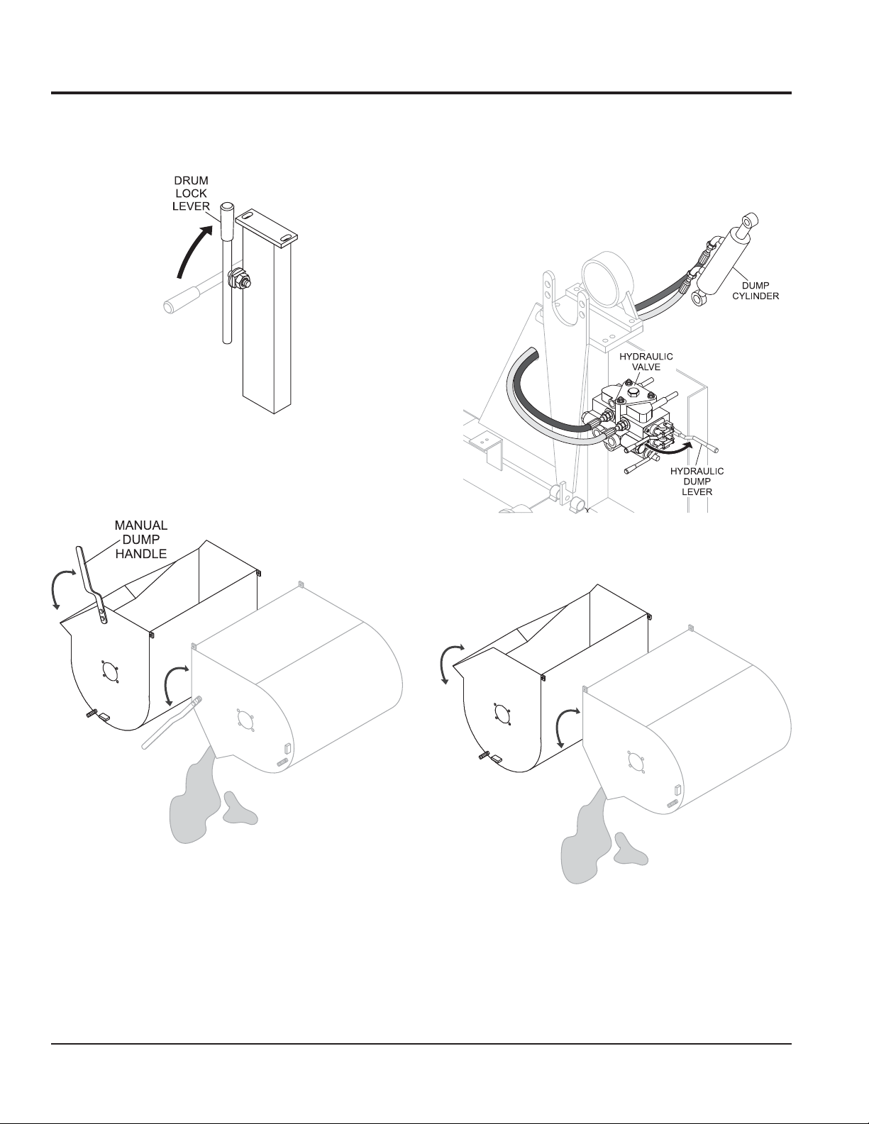
DUMPING (MANUAL)
1. Release drum lock lever by pushing lever into vertical
position (Figure 25).
Figure 25. Drum Lock Lever
2. Pull dump handle downward to discharge (empty) the
drum. Move dump handle upward to return it to vertical
position. (Figure 26).
DUMPING (HYDRAULIC)
1. If operating a mixer with hydraulic dump capability, pull
hydraulic dump lever (Figure 27) outward to place drum
in dump position (Figure 28).
Figure 26. Manual Dump Handle
3. Drum lock lever automatically moves back to horizontal
position, locking the drum back into vertical position.
2. Push hydraulic dump lever inward to place drum back
4. Inspect for proper functionality before starting the engine
or engaging blades. Any binding of material between the
mixing blades and drum will cause the handle to quickly
rotate if not in the “up and locked” position.
Figure 27. Hydraulic Dump Lever
Figure 28. Hydraulic Dump
in vertical position.
PAGE 26 — WM120PH/SH HYDRAULIC MIXER • OPERATION AND PARTS MANUAL — REV. #7 (09/15/11)
Page 27
SHUT-DOWN
STOPPING THE MIXER (GASOLINE ENGINE)
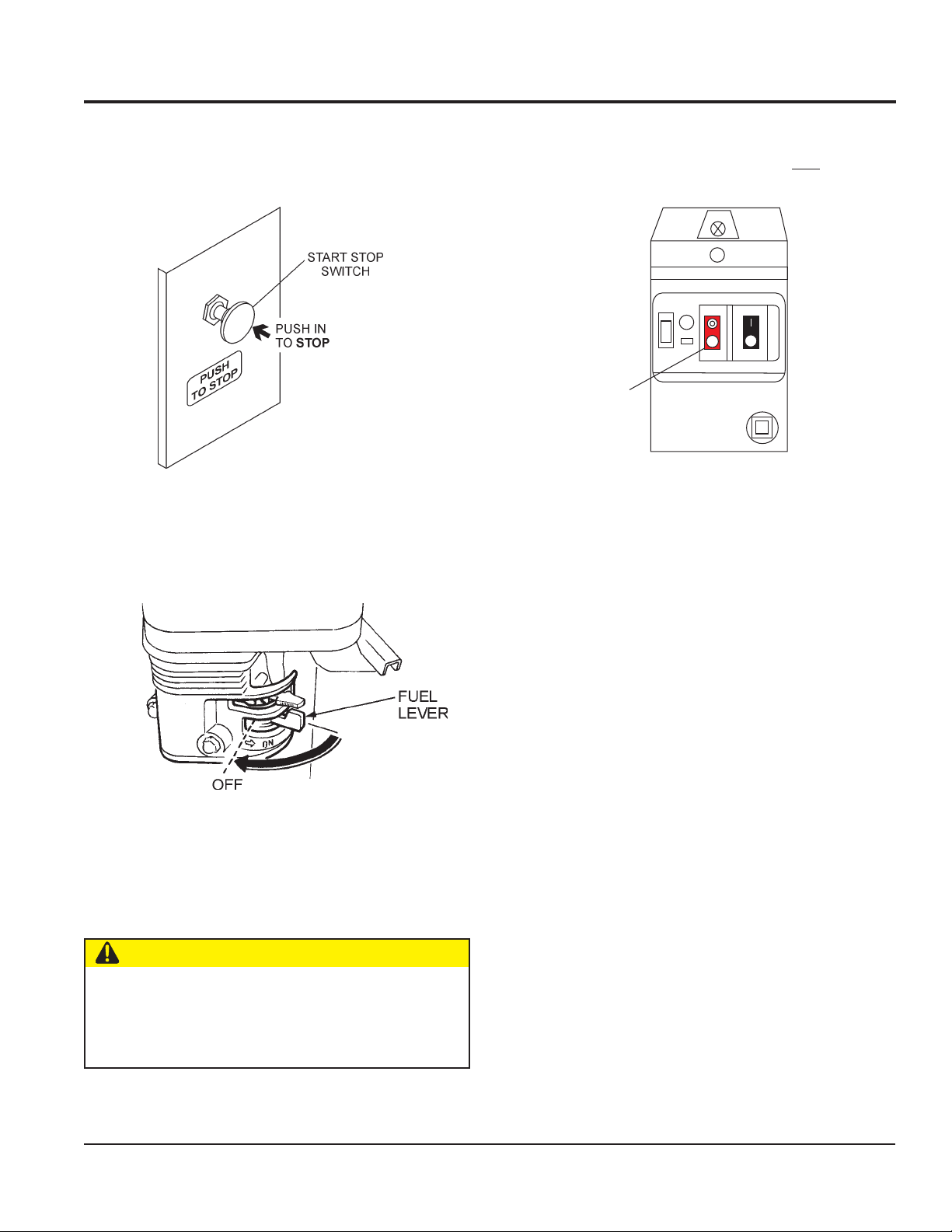
1. Push the
the engine.
2. Place the fuel valve (Figure 30) lever to the OFF
position.
start/stop
switch (Figure 29) inward to stop
Figure 29. Start/Stop Switch (Stop)
STOPPING THE MIXER (ELECTRIC MOTOR)
1. To stop the electric motor, press the
switch (Figure 31).
ON
OFF
START
STOP
PRESS TO
STOP
Figure 31. Electric Motor On/OFF Switch (Stop)
2. Disconnect the electric motor's extension cord from
its power source.
3. Clean mixer as referenced in the maintance section of
this manual.
red
OFF/STOP
Figure 30. Fuel Valve Lever (Off)
3. Clean mixer as referenced in the maintenance section
of this manual.
CAUTION —Start/Stop Switch
NEVER disable or disconnect the start/stop switch. It
is provided for operator safety.
Serious Injury
may
result if it is disabled, disconnected or improperly
maintained.
WM120PH/SH HYDRAULIC MIXER • OPERATION AND PARTS MANUAL — REV. #7 (09/15/11) — PAGE 27
Page 28

MAINTENANCE (ENGINE)
Use Table 8 as a general maintenance guideline when servicing your engine. For more detail engine maintenance information,
refer to the engine owner's manual supplied with your engine.
ELUDEHCSECNANETNIAMENIGNE.8ELBAT
TSRIF
)3(NOITPIRCSEDNOITAREPOEROFEB
KCEHCX
liOenignE
EGNAHCX X
KCEHCX
renaelCriA
EGNAHC)1(X
stloB&stuNllA
gulPkrapS
sniFgnilooCKCEHCX
retserrAkrapSNAELC X
knaTleuFNAELC X
fInethgit-eR
yrasseceN
NAELC-KCEHCX
ECALPER X
X
HTNOM
RO
.SRH01
YREVE
SHTNOM3
RO
.SRH52
YREVE
SHTNOM6
RO
.SRH05
YREVE
RAEY
RO
01
.SRH0
YREVE
SRAEY2
RO
.SRH002
retliFleuFKCEHC X
deepSeldITSUJ
ecnaraelCevlaVTSUJDA-KCEHC )2(X
senilleuFKCEHC )2()yrassecenfiecalper(sraey2yrevE
neuqerferomecivreS)1( YTSUD .saera
DA-KCEHC )2(X
nidesunehwylt
.serudecorpecivresroflaunaMpohSADNOHehtotrefeR.tneiciforp
amreporpenimretedotnoitarepofosruohgol,esulaicremmocroF)3(
.slavretniecnanetni
yllacinahcemeradnaslootreporpehtevahuoysselnu,relaedecivresruoyybdecivresebdluohssmetiesehT)2(
PAGE 28 — WM120PH/SH HYDRAULIC MIXER • OPERATION AND PARTS MANUAL — REV. #7 (09/15/11)
Page 29
MAINTENANCE (ENGINE)
MAINTENANCE
Perform the scheduled maintenance procedures as defined
by Table 8 and below:
Daily
■
Thoroughly remove dirt and oil from the engine and
control area. Clean or replace the air cleaner elements
as necessary. Check and retighten all fasteners as
necessary. Check the gearbox for oil leaks. Repair or
replace as needed.
3. Replace engine oil with recommended type oil as listed
4. Install drain bolt with sealing washer and tighten
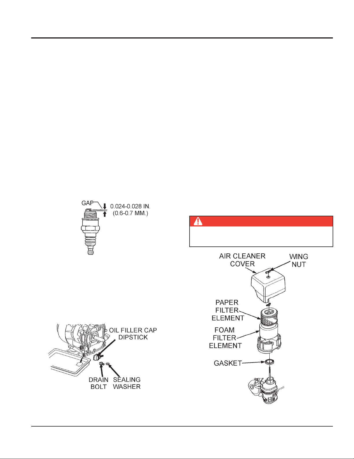
ENGINE AIR CLEANER
1. Remove the air cleaner cover and foam filter element
2. Tap the paper filter element (Figure 34) several times
Weekly
■
Remove the fuel filter cap and clean the inside of the
fuel tank.
■
Remove or clean the filter at the bottom of the tank.
■
Remove and clean the spark plug (Figure 32), then adjust
the spark gap to 0.024 ~0.028 inch (0.6~0.7 mm). This
unit has electronic ignition, which requires no
adjustments.
3. Clean foam element in warm, soapy water or
in Table 6. For engine oil capacity, see Table 2 (engine
specifications). DO NOT overfill.
securely.
as shown in Figure 34.
on a hard surface to remove dirt, or blow compressed
air [not exceeding 30 psi (207 kPa, 2.1 kgf/cm2)] through
the filter element from the air cleaner case side.
brush off dirt. Brushing will force dirt into the fibers.
Replace the paper filter element if it is excessively
dirty.
nonflammable solvent. Rinse and dry thoroughly. Dip
the element in clean engine oil and completely squeeze
out the excess oil from the element before installing.
NEVER
DO NOT use gasoline as a cleaning solvent to avoid
creating the risk of fire or an explosion.
Figure 32. Spark Plug Gap
ENGINE OIL
1. Drain the engine oil when the oil is
Figure 33.
2. Remove the oil drain bolt and sealing washer and allow
the oil to drain into a suitable container.
warm
as shown in
DANGER — Explosive Hazard
Figure 33. Engine Oil (Draining)
Figure 34. Engine Air Cleaner
WM120PH/SH HYDRAULIC MIXER • OPERATION AND PARTS MANUAL — REV. #7 (09/15/11) — PAGE 29
Page 30
MAINTENANCE (MIXER)
DRUM HEAD SEALS
There is 1 set of drum head seals (Figure 35) that will require
lubrication. Lubricate the grease fitting for each drum seal
after each use
using any grade lithium base grease. Apply
BALL SOCKET AND CLAMP FACE MAINTENANCE
1. If the towing vechicle is equipped with a ball socket,
grease until visible inside of mixing drum (over grease).
This will purge seal system of contamination.
GREASE FITTING
AND CAP
DRUM HEAD
SEALS
GREASE FITTING
AND CAP
2. Periodically oil
3. When parking or storing your mixer. Keep the coupler
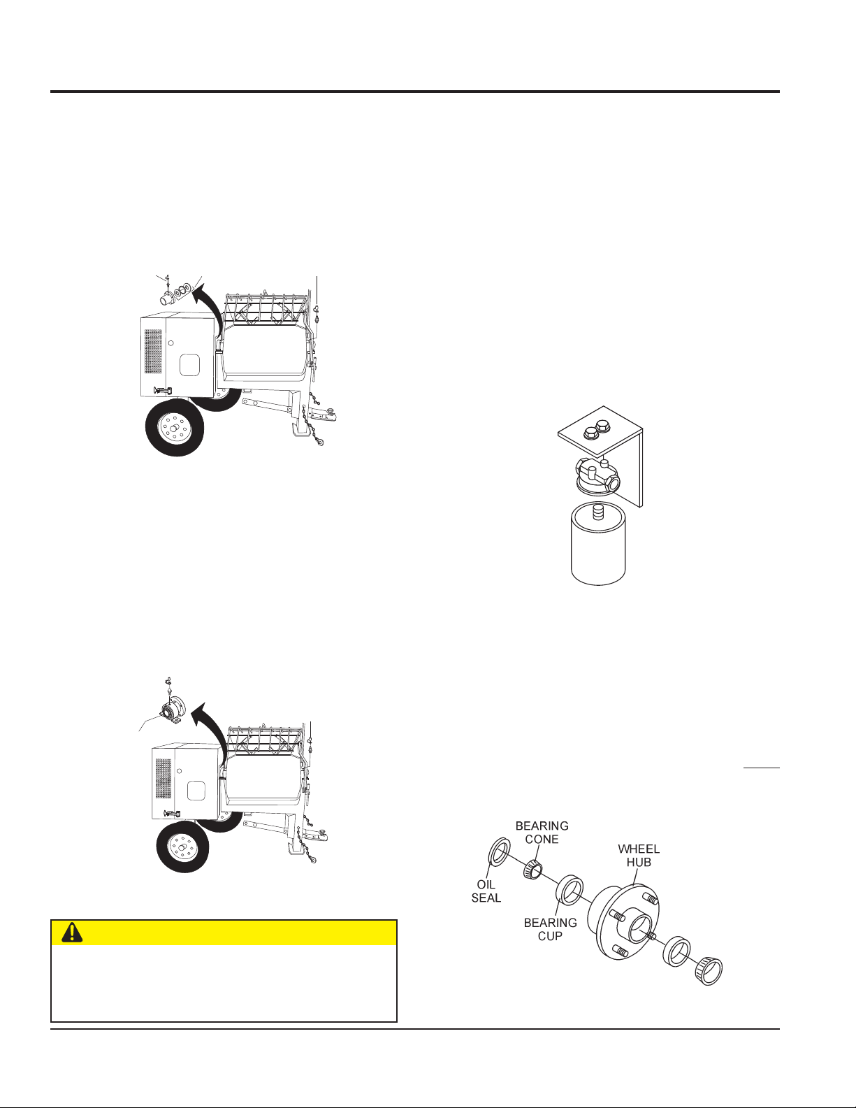
HYDRAULIC OIL FILTER
Replace hydraulic oil filter (Figure 37) every 500 hours.
Hydraulic tank capacity is 12 gallons (45 liters). Refill with
any of the following hydraulic oil types. Shell Tellius 68,
Mobil DFE26 or Texaco Rand HDC.
Figure 35. Grease Fittings (Drum Head Seals)
smear socket periodically with multi-purpose grease.
This will keep the ball socket well lubricated.
pivot points
and
clamp face
surfaces
of coupler with SAE 30 WT. motor oil.
off the ground so dirt will not build up in the ball socket.
DRUM BEARING BRACKET LUBRICATION
There is 1 set of drum bearing brackets (Figure 36) that will
require lubrication. These brackets are intended to make
the drum rotate freely. Lubricate the grease fitting for each
drum bearing bracket
becomes difficult to position
grease.
GREASE FITTING
every month or when the drum
using multi-purpose grade
AND CAP
WHEEL BEARINGS
1. After every 3 months of operation, remove the hub
dust cap and inspect the wheel bearings (Figure 38).
Once a year, or when required, disassemble the wheel
hubs remove the old grease and repack the bearings
forcing grease between rollers, cone and cage with a
DRUM BEARING
BRACKET
GREASE FITTING
AND CAP
good grade of high speed wheel bearing grease (
use grease heavier than 265 A.S.T.M. penetration (“No.
2.”)
Figure 36. Grease Fittings (Dumping Mechanism)
Figure 37. Hydraulic Oil Filter
never
CAUTION — Lubricate Grease Fittings
Failure
to lubricate the drum bearing grease fittings
eriodically will cause the dumping mechanism to stiffen,
making the mixing drum hard to dump.
Figure 38. Wheel Hub and Bearings
PAGE 30 — WM120PH/SH HYDRAULIC MIXER • OPERATION AND PARTS MANUAL — REV. #7 (09/15/11)
Page 31

MAINTENANCE (MIXER)
TIRES/WHEELS/LUG NUTS
Tires and wheels are a very important and critical
components of the trailer. When specifying or replacing
the trailer wheels it is important the wheels, tires, and axle
are properly matched.
WARNING — Damaged Wheels
DO NOT attempt to repair or modify a
wheel. DO NOT install an inter-tube
to correct a leak through the rim. If
the rim is cracked, the air pressure in
LUG NUT TORQUE REQUIREMENTS
It is extremely important to apply and maintain proper wheel
mounting torque. Be sure to use only the fasteners matched
to the cone angle of the wheel. Proper procedure for
attachment of the wheels is as follows:
1. Start all wheel lug nuts by hand.
2. Torque all lug nuts in sequence. See Figure 39. DO
NOT torque the wheel lug nuts all the way down. Tighten
each lug nut in 3 separate passes as defined by Table
10.
the inter-tube may cause pieces of the
rim to explode (break-off) with great force and can cause
serious eye or bodily injury.
TIRES WEAR/INFLATION
Tire inflation pressure is the most important factor in tire
life. Pressure should be checked cold before operation.
DO NOT bleed air from tires when they are hot. Check
inflation pressure weekly during use to insure the maximum
tire life and tread wear.
eziSleehW
ssaPtsriF
SBL-TF
ssaPdnoceS
SBL-TF
"2152-0204-5356-05
"3152-0204-5356-05
"4152-0206-05021-09
"5152-0206-05021-09
STNEMERIUQEREUQROTERIT.01ELBAT
ssaPdrihT
SBL-TF
WARNING — Eyesight Hazard
ALWAYS
wear safety glasses when
removing or installing force fitted
parts. Failure to comply may result in
serious injury.
Table 9 (Tire Wear Troubleshooting) will help pinpoint the
causes and solutions of tire wear problems.
TABLE 9.TIRE WEAR TROUBLESHOOTING
WEAR PATTERN SOLUTION
Center Wear
Edge Wear Under Inflation
Side Wear
Toe Wear
Cupping
Flat Spots
CAUSE
Over Inflation
Loss of chamber
or overloading.
Incorrect toe-in
Out-of balance
Wheel lockup &
tire skidding.
Adjust pressure to
particular load per
tire manufacturer.
Adjust pressure to
particular load per
tire manufacturer.
Make sure load does
not exceed axle rating.
Align wheels.
Align wheels.
Check bearing adjustment and balance tires.
Avoid sudden stops
when possible and
adjust brakes.
"6152-0206-05021-09
NEVER!
use an pneumatic air gun to tighten
wheel lug nuts.
WM120PH/SH HYDRAULIC MIXER • OPERATION AND PARTS MANUAL — REV. #7 (09/15/11) — PAGE 31
Page 32

MAINTENANCE (MIXER)
3. After first road use, retorque all lug nuts in sequence.
Check all wheel lug nuts periodically.
SUSPENSION
The suspension type axle and associated hardware (Figure
40) should be periodically inspected for signs of excessive
wear, elongation of bolt holes, and loosening of fasteners.
Replace all damaged parts immediately.
MIXER CLEANING
It is important that the drum interior is free of dried material.
Obstructions can cause the paddle blades to lock against
the drum resulting in sudden dump handle movement.
Figure 40. Axle Support Components
Figure 39. Wheel Lug Nuts Tightening Sequence
1. Stop the engine. Push the engine “Kill” button to the
“OFF” position.
2. Place the hydraulic paddle lever (Figure 5) in "neutral"
position do disengage.
3.
ALWAYS disconnect the spark plug wire
engines) before cleaning the inside of the drum. If mixer
is equipped with an electric motor
from AC power source
clutch engagement lever is
4. Place “Do Not Operate” tag on mixer.
5. Make sure the rear section of safety grate is connected
to the mixing drum.
6. At the end of each day’s operation, place mixer drum
in an upright position and spray inside of tub
immediately with water to prevent lumps of dried mortar
or plaster from forming and contamination of future
batches, DO NOT allow a buildup of materials to form
on the blades or anywhere inside the drum.
7. Rotate mixer to dump position and remove debris.
. In addition make sure the
remove power cord
disengaged
(gasoline
.
8.
Thoroughly clean
and frame.
PAGE 32 — WM120PH/SH HYDRAULIC MIXER • OPERATION AND PARTS MANUAL — REV. #7 (09/15/11)
the entire mixer, wheels, cabinet
Page 33

MAINTENANCE (MIXER)/STORAGE
9.
NEVER!
motor (Figure 41).
10. When cleaning of the entire mixer is done, return
mixing drum to an upright position.
WARNING — Keep Hands Clear of Drum
When rotating the mixing drum from the dump position
to the upright position, keep hands clear of safety
grate. The possibility exists of hands or fingers being
crushed (Figure 42).
pour or spray water over the engine or electric
Figure 41. No Spraying of Water
MIXER STORAGE
For storage of the mixer for over 30 days, the following is
recommended:
Drain the fuel tank completely, or add STA-BIL to the
fuel.
Run the engine until the fuel is completely
consumed.
Completely drain used oil from the engine crankcase
and fill with fresh clean oil, then follow the procedures
described in the engine manual for engine storage.
Clean the entire mixer and engine compartment.
Place the mixing drum in the down position (mouth facing
downward).
Cover the mixer and place it a clean dry area, that is
protected from harsh elements.
Figure 42. Safety Grate (Crush Hazard)
WARNING — Disengaged Drum Lock
DO NOT start engine or engage paddle arms when drum
lock lever is not engaged.
WM120PH/SH HYDRAULIC MIXER • OPERATION AND PARTS MANUAL — REV. #7 (09/15/11) — PAGE 33
Page 34

TROUBLESHOOTING (ENGINE)
Practically all breakdowns can be prevented by proper handling and maintenance inspections, but in the event of a
breakdown, please take a remedial action following the diagnosis based on the
Troubleshooting (Tables 11,12, and 13) information shown below and on the proceeding pages. If the problem cannot be
remedied, please leave the unit just as it is and consult or company's service department.
MOTPMYS MELBORPELBISSOP NOITULOS
Engine, Mixer
GNITOOHSELBUORTENIGNE.11ELBAT
and
Electric Motor
?tignihcaersi
?leuFoN leuFddA
?knatleufniretaW .knatleufecalperrohsulF
?deggolcretlifleuF retlifleufecalpeR
?roterubrackcutS .msinahcemtaolfkcehC
gnitratsrooP
?gulp
?liooN .deriuqersalioddA
?esool
?dersigulpkrapS .tinunoitingirotsinartkcehC.deluofsigulpkrapS
?gnitratsnopu
leuffieesotroterubractcepsnI
?etihw-eulbsigulpkrapS
krapsfopittatneserpkrapsoN
/tratS
sknilbpmalmralaerusserpliO
?revonruttonlliwenignE .tniojlexayrassecenfidnanotsipdnarednilycecalpeR
stlobgnitcennocdaehrednilyC
enilleufkcehC
erastejroterubraC.gnikaelriadetcejni,noisserpmoctneiciffusnI
.)wolfrevo(deggolc
.nekorbrodekcarcdrocegatlovhgih,nekorbtinunoitingirotsinarT
.deluoffigulpkrapsecalpeR.nekorbhctiwspotS
."rosneslio"tiucricnwodtuhscitamotuAkcehC
.stlobgnitcennocdaehrednilycnethgiT
"noisserpmoc
"noisserpmoc"
on"tuptuorewoptneiciffusnI
?esoolsigulpkrapS .gulpkrapsecalpeR
?sgnirnotsipnroW .sgnirnotsipecalpeR
tuptuorewoptneiciffusnI
?daeh
?degamadteksagdaehrednilyC .teksagdaehrednilycecalpeR
?taesevlavfonoitcnuflaM .sevlavtaes-eR
renaelc-rianinoitcnuflaM
?deggolcretlifria,metsys
ecafretnimorfnignikaelriA
rednilycdnaroterubracneewteb
?metsysleufninoitcnuflaM
.retlifriaecalperronaelC
ecalpeR.daehrednilycdnaroterubracneewtebstlobnethgiT
.teksagdaehrednilyc
.retlifleufecalperronaelC
.roterubracecalperronaelC
.taolfroterubrackcehC
PAGE 34 — WM120PH/SH HYDRAULIC MIXER • OPERATION AND PARTS MANUAL — REV. #7 (09/15/11)
Page 35

TROUBLESHOOTING (ENGINE)
MOTPMYS MELBORPELBISSOP NOITULOS
)DEUNITNOC(GNITOOHSELBUORTENIGNE.11ELBAT
tuptuorewoptneiciffusnI
staehrevodna"noisserpmoc"
leufhcumotsnruB
ylsuoinitnocsiroloctsuahxE
"ETIHW"
ylsuoinitnocsiroloctsuahxE
"KCALB"
?stcudorp
?ytisocsiv
?sgnirnroW sgnirecalpeR
?nafgniloocninoitcnuflaM .nafgniloocecalperrokcehC
?deggolcretlifekat-niriA .retlifekat-niriaecalperronaelC
tsuahxefonoitalumuccarevO
?gulpkrapsgnorW .gulpkrapsepytdetseggusserutcafunamhtiwgulpkrapsecalpeR
gnorwsiliognitacirbuL
?deggolcrennaelcriA .renaelcriaecalperronaelC
ottesneebtonsahevlavekohC
?noitisoptcerroceht
nolaes,evitcefedroterubraC
?nekorbroterubrac
tnemtsujdaroterubracrooP
?hcirootsnurenigne"
.sevlavkcehcdnanaelC
.yrassecenfiecalper,relffumkcehC
.ytisocsivtcerrochtiwliognitacirbulecalpeR
.noitisoptcerrocehtotevlavekohctsujdA
.laesroroterubracecalpeR
.roterubractsujdA
WM120PH/SH HYDRAULIC MIXER • OPERATION AND PARTS MANUAL — REV. #7 (09/15/11) — PAGE 35
Page 36

TROUBLESHOOTING (MIXER/ELECTRIC MOTOR)
GNITOOHSELBUORTREXIM.21ELBAT
MOTPMYS MELBORPELBISSOP NOITULOS
,yvaehootdaollairetaM
?ytilibapacreximgnideecxe
gniximedisnikcutstcejbO
elddapgnimmaj,murd
?noitator
.noitcurtsbo
evlavfeilertcerrocnI
.etatortonlliwsedalB
?erusserp
.deximgnieblairetamfotnuomaecudeR
evomeR.stnetnocmurdtuoytpmE.enignepotS
.erusserpfeilerISP0571reporproftcepsnI
.deepsenignekcehC .0063MPRreporP
rorotomciluardyhevitcefeD
?pmup
rednilycciluardyhwolS
?gnipmud
murdmorfgnikaellairetaM
.sdne
?slaestfahs
elddapevitcefedronroW
.slaesecalpeR
.laesrednilycevitcefeD
murdnrowroevitcefeD
egrahcsidottluciffidmurD
?stekcarbtroppus
)tlit(
.thgitootdetsujdasedalB
.murd
.secivreSlacinhceTQMtcatnoC
.ecalperrotekcarbotesaergylppA
fosllawedishcuottsomlayehtlitnusedalbtsujdA
GNITOOHSELBUORTROTOMCIRTCELE.31ELBAT
MOTPMYS MELBORPELBISSOP NOITULOS
?rotomotegatlovoN .ecruosrewopkcehC
?drocnoisnetxeevitcefeD .drocnoisnetxeecalpeR
.etatortonlliwsedalB
?hctiwsFFO/NOrotomevitcefeD .hctiwsecalpeR
?sgnidniwrotomevitcefeD .sgnidniwecalperrosgnidniwriapeR
PAGE 36 — WM120PH/SH HYDRAULIC MIXER • OPERATION AND PARTS MANUAL — REV. #7 (09/15/11)
Page 37

WIRING DIAGRAM (ELECTRIC MOTOR)
WHITE/NEUTRAL
X
230 VAC 1Ø
L6-30P/L1620P
TWIST-LOCK
Y
BLACK/LINE
TWIST-LOCK
2-POLE/3-WIRE
GROUNDING
G
GREEN/GROUND
L6-30P
SINGLE OR THREE PHASE
ELECTRIC MOTOR
ELECTRIC CABLE
PIGTAIL END
WHITE/NEUTRAL
X
460 VAC 3Ø
Y
BLACK/LINE
Z
RED/LINE
L16-20P
TWIST-LOCK
Figure 43. Electric Motor Wiring Diagram
3-POLE/4-WIRE
GROUNDING
G
GREEN/GROUND
WM120PH/SH HYDRAULIC MIXER • OPERATION AND PARTS MANUAL — REV. #7 (09/15/11) — PAGE 37
Page 38

HYDRAULIC SYSTEM DIAGRAM
HYDRAULIC SYSTEM DIAGRAM
RETURN
FILTER
TANK
BYPASS
25 PSI
HYDRAULIC
DUMP
CYLINDER
FORWARD/REVERSE
2
1
RELIEF
VALV E
1750 PSI
RELIEF
VALV E
1750 PSI
HYD
MOTOR
GEAR
PUMP
TANK
POWER
SUCTION
STRAINER
SHOWN WITH OPTIONAL HYDRAULIC DUMP
Figure 44. Hydraulic System Diagram
PAGE 38 — WM120PH/SH HYDRAULIC MIXER • OPERATION AND PARTS MANUAL — REV. #7 (09/15/11)
Page 39

NOTES
WM120PH/SH HYDRAULIC MIXER • OPERATION AND PARTS MANUAL — REV. #7 (09/15/11) — PAGE 39
Page 40

EXPLANATION OF CODE IN REMARKS COLUMN
The following section explains the different symbols and
remarks used in the Parts section of this manual. Use the
help numbers found on the back page of the manual if there
are any questions.
NOTICE
The contents and part numbers listed in the parts
section are subject to change without notice. Multiquip
does not guarantee the availability of the parts listed.
SAMPLE PARTS LIST
NO. PART NO. PART NAME QTY. REMARKS
1 12345 BOLT ......................1 .....INCLUDES ITEMS W/%
2% WASHER, 1/4 IN. ...........NOT SOLD SEPARATELY
2% 12347 WASHER, 3/8 IN. ...1 .....MQ-45T ONLY
3 12348 HOSE ..................A/R ...MAKE LOCALLY
4 12349 BEARING ..............1 .....S/N 2345B AND ABOVE
NO. Column
Unique Symbols — All items with same unique
symbol
(@, #, +, %, or >) in the number column belong to the
same assembly or kit, which is indicated by a note in the
“Remarks” column.
Duplicate Item Numbers — Duplicate numbers indicate
multiple part numbers, which are in effect for the same
general item, such as different size saw blade guards in
use or a part that has been updated on newer versions
of the same machine.
NOTICE
When ordering a part that has more than one item
number listed, check the remarks column for help in
determining the proper part to order.
PART NO. Column
Numbers Used — Part numbers can be indicated by a
number, a blank entry, or TBD.
TBD (To Be Determined) is generally used to show a
part that has not been assigned a formal part number
at the time of publication.
A blank entry generally indicates that the item is not sold
separately or is not sold by Multiquip. Other entries will
be clarified in the “Remarks” Column.
QTY. Column
Numbers Used — Item quantity can be indicated by a
number, a blank entry, or A/R.
A/R (As Required) is generally used for hoses or other
parts that are sold in bulk and cut to length.
A blank entry generally indicates that the item is not sold
separately. Other entries will be clarified in the “Remarks”
Column.
REMARKS Column
Some of the most common notes found in the “Remarks”
Column are listed below. Other additional notes needed
to describe the item can also be shown.
Assembly/Kit — All items on the parts list with the
same unique symbol will be included when this item is
purchased.
Indicated by:
“INCLUDES ITEMS W/(unique symbol)”
Serial Number Break — Used to list an effective serial
number range where a particular part is used.
Indicated by:
“S/N XXXXX AND BELOW”
“S/N XXXX AND ABOVE”
“S/N XXXX TO S/N XXX”
Specific Model Number Use — Indicates that the part
is used only with the specific model number or model
number variant listed. It can also be used to show a
part is NOT used on a specific model or model number
variant.
Indicated by:
“XXXXX ONLY”
“NOT USED ON XXXX”
“Make/Obtain Locally” — Indicates that the part can
be purchased at any hardware shop or made out of
available items. Examples include battery cables, shims,
and certain washers and nuts.
“Not Sold Separately” — Indicates that an item cannot
be purchased as a separate item and is either part of an
assembly/kit that can be purchased, or is not available
for sale through Multiquip.
PAGE 40 — WM120PH/SH HYDRAULIC MIXER • OPERATION AND PARTS MANUAL — REV. #7 (09/15/11)
Page 41

SUGGESTED SPARE PARTS
WM120PS 1 TO 3 UNITS
Qty. P/N Description
6 ............ 491010 ............ RUBBER LATCH ASSY.
1 ............ EM200293A .... PADDLE ARM TOW SIDE
1 ............ EM200294A .... PADDLE ARM CENTER TOW SIDE
1 ............ EM200295A .... PADDLE ARM CENTER ENGINE SIDE
1 ............ EM200296A .... PADDLE ARM ENGINE SIDE
3 ............ EM200863 ...... RUBBER BLADE KIT (STEEL DRUM)
3 ............ EM204625 ...... RUBBER BLADE KIT (PLASTIC DRUM)
4 ............ EM200297 ...... U-BOLT
2 ............ 3530 ................ PADDLE SHAFT, SEAL KIT
2 ............ EM902153 ...... BEARING, PADDLE SHAFT
WM120PS 5 TO 10 UNITS
Qty. P/N Description
10 .......... 491010 ............ RUBBER LATCH ASSY.
2 ............ EM200293A .... PADDLE ARM TOW SIDE
2 ............ EM200294A .... PADDLE ARM CENTER TOW SIDE
2 ............ EM200295A .... PADDLE ARM CENTER ENGINE SIDE
2 ............ EM200296A .... PADDLE ARM ENGINE SIDE
6 ............ EM200863 ...... RUBBER BLADE KIT (STEEL DRUM)
3 ............ EM204625 ...... RUBBER BLADE KIT (PLASTIC DRUM)
16 .......... EM200297 ...... U-BOLT
4 ............ 3530 ................ PADDLE SHAFT, SEAL KIT
4 ............ EM902153 ...... BEARING, PADDLE SHAFT
WM120PH/SH HYDRAULIC MIXER • OPERATION AND PARTS MANUAL — REV. #7 (09/15/11) — PAGE 41
Page 42

NAMEPLATE AND DECALS
PAGE 42 — WM120PH/SH HYDRAULIC MIXER • OPERATION AND PARTS MANUAL — REV. #7 (09/15/11)
Page 43

NAMEPLATE AND DECALS
NO. PART NO. PART NAME QTY. REMARKS
1 DCL151 DECAL, TOWING INSTRUCTIONS 2
2 EM948630 DECAL, PUSH TO STOP 1
3 DCL160A DECAL, CRUSH WARNING 2
4 515275 DECAL, WHITEMAN LOGO (SMALL) 3
5 504713 DECAL, SAFETY INSTRUCTIONS 1
6 35137 DECAL, WARNING READ 1
7 504714 DECAL, WHITEMAN LOGO (LARGE) 3
8 513479 DECAL, WARNING SAFETY GRATE 1
9 DCL335 DECAL, CRUSH WARNING SAFETY GRATE 1
10 DCL280 DECAL, WARNING DUMP HANDLE 1
11 13238 DECAL, CONTROLS, MOLD-IN 1
12 13118 DECAL, POWDER COATED 1
13 NAMEPLATE........................................................ 1 ......... CONTACT PARTS DEPT.
WM120PH/SH HYDRAULIC MIXER • OPERATION AND PARTS MANUAL — REV. #7 (09/15/11) — PAGE 43
Page 44

PADDLE BLADES ASSY.
6
SIDE
5
E
N
D
2
CENTER
ENGINE END
ENGINE END
SIDE
9
CENTER
TOW END
8
7
2
8
7
7
2
15
5
3
SIDE
16
18
E
N
D
SIDE
OR
E
S
N
C
D
R
A
P
E
P
R
R
O
U
L
B
Y
B
E
R
10
S
I
D
E
S
C
P
O
R
A
P
E
L
Y
O
R
R
R
U
R
B
E
B
17
10
13
19
WIPER
AND
SCRAPPER
HARDWARE
KIT
TOW
END
11
14
12
PAGE 44 — WM120PH/SH HYDRAULIC MIXER • OPERATION AND PARTS MANUAL — REV. #7 (09/15/11)
Page 45

PADDLE BLADES ASSY.
NO. PART NO. PART NAME QTY. REMARKS
2 492584 NUT, LOCK 1/2" 8
3 EM200295A PADDLE ARM, CENTER TOW END 1
5 EM200292 INSERT, PADDLE ARM 8
6 EM200293A PADDLE ARM, TOW END 1
7 6109170 WASHER, FLAT 1/2" 8
8 EM200297 U-BOLT, END PADDLES 4
9 EM200294A PADDLE ARM, CENTER ENGINE END 1
10
# 492366 SCREW, HHC 5/16-18 X 1-1/2 G5 14
*
11
# EM923023 WASHER, FLAT 5/16" STEEL 28
*
12# 13352 WIPER, SIDE (PLASTIC) ............................................... 4 ............ PLASTIC DRUM
12
13
14
15
16 EM200296A PADDLE ARM, ENGINE END 1
17
18# EM507518 BLADE, PLASTIC (END) ................................................ 2 ............ PLASTIC DRUM
18
19 EM200863 KIT, RUBBER BLADES, SCRAPERS & HARDWARE .... 1 ............ INCLUDES ITEMS W/
19 EM204625 KIT, PLASTIC BLADES, SCRAPERS & HARDWARE .... 1 ............ INCLUDES ITEMS W/#
EM200212 WIPER, SIDE (RUBBER) ............................................... 4............ STEEL DRUM
*
# EM203432 SCRAPPER, SIDE .......................................................... 4 ............ PLASTIC/STEEL DRUMS
*
# 2105164 NUT, HEX 5/16" 14
*
# EM923343 WASHER, LOCK 5/16" 14
*
EM203433 SCRAPPER, END ........................................................... 2 ............ PLASTIC/STEEL DRUMS
*
EM200213 BLADE, RUBBER (END) ................................................. 2............ STEEL DRUM
*
....................................................................................................... STEEL DRUM ONLY
....................................................................................................... PLASTIC DRUM ONLY
*
WM120PH/SH HYDRAULIC MIXER • OPERATION AND PARTS MANUAL — REV. #7 (09/15/11) — PAGE 45
Page 46

PLASTIC MIXING DRUM ASSY.
PAGE 46 — WM120PH/SH HYDRAULIC MIXER • OPERATION AND PARTS MANUAL — REV. #7 (09/15/11)
Page 47

PLASTIC MIXING DRUM ASSY.
NO PART NO PART NAME QTY. REMARKS
1# 3309 GRATE, MOVABLE 1
2# EM963057 HHCS 3/8 X 1-1/2" 6
3# 13270 GRATE, STATIONARY 1
4# EM969013 NUT, NYLOC 3/8-16 8
5# 6109170 WASHER, FLAT 1/2" .......................................... 2............ MANUAL DUMP ONLY
6# 504943 SCREW, FLATHEAD 3/8" NC X 2 8
7# 3006 SUPPORT DISK 2
8# 507719 BEARING HOUSING 2
9# 511910 FHCS 1/4" NC X 1-1/4" G5 8
10# EM963692 HHCS 1/2-13" X 1-1/2" G5 ................................. 2............ MANUAL DUMP ONLY
11# EM923025 WASHER, FLAT 3/8" 2
12# 13209 REAR DRUM SUPPORT 1
13# 491008 CAP, GREASE FITTING 4
14# EM916019 GREASE FITTING 4
15# 492581 LOCK NUT, NYLON 1/4-20 8
16# EM621 WASHER, FLAT 1/2" SPECIAL 4
17# EM963105 SCREW, HHCS 1/2" NC X 2" G5 ....................... 4............ REPLACES EM492396
18# 10176 NUT, LOCK 1/2"-13 ............................................ 2............ MANUAL DUMP ONLY
19 13228 PIN, DUMP CYLINDER 1
20 3327 CYLINDER, DUMP 1
21 511495 LOCK NUT 1" NC 1
22 511526 SCREW HHCS 1" NC X 8 1
23 509000 COTTER PIN 3/16" X 2" 1
24 3047 SPACER, 2" X 1-1/8 X 1/4" L 2
25 13286 SPACER, HYDRAULIC CYLINDER 1
26# EM963610 HHCS 3/8" NC X 1-1/4" G8 2
27# 3485 DRUM SUPPORT 1
28# 3382 LATCH, TUB STAY 1
29# 2219 PIN, COTTER 1/8" X 1-1/2" 1
30# 3249 CAP, DUST 1
31# 13218 DUMP BEARING HOUS. BRACKET REAR 1
32# 3500 DUMP BEARING HOUS. BRACKET FRONT 1
33 EM201537 MANUAL DUMP HANDLE.................................. 1............ MANUAL DUMP ONLY. DO NOT USE
.......................................................................................... ON HYDRAULIC DUMP MACHINE.
34# 3042 MIXER DRUM, PLASTIC, BARE 1
35# 925191 PIN, HITCH CLIP 1
36# 0401450160 WASHER, FLAT 16 MM ZINC ............................ 1 ............ REPLACES 492602
37# 511493 BAR, GRATE LATCH 1
38# EM963692 HHCS 1/2"-13 X 1-1/2" 1
39# 492584 NUT, LOCK 1/2" 7
40# 8151 WASHER, FLAT SAE 3/4" 1
41 512181 DRUM AND SHAFT ASSY. MAN./HYD. DUMP .. 1 ............ INCLUDES ITEMS W/#
WM120PH/SH HYDRAULIC MIXER • OPERATION AND PARTS MANUAL — REV. #7 (09/15/11) — PAGE 47
Page 48

STEEL DRUM ASSY. (MANUAL)
PAGE 48 — WM120PH/SH HYDRAULIC MIXER • OPERATION AND PARTS MANUAL — REV. #7 (09/15/11)
Page 49

STEEL DRUM ASSY. (MANUAL)
NO PART NO PART NAME QTY. REMARKS
1# EM203449 GRATE, MOVABLE 1
2# 7170 5/32" 3-5/16" 2
3# 6109170 WASHER, FLAT 1/2" 3
4# 13276 BAR, GRATE LATCH 1
5# EM969013 NUT, NYLOC 3/8" 8
6# EM621 WASHER, FLAT 1/2" SPECIAL 4
7# 491008 CAP, GREASE FITTING 4
8# EM916019 GREASE FITTING 4
9# EM963105 SCREW, HHCS 1/2" NC X 2" G5 ............... 4........... REPLACES EM492396
10# 13260 FRONT DUMP SUPPORT BRACKET 1
11# 3249 CAP, DUST 1
12# EM963610 HHCS 3/8" NC X 1-1/4" G8 8
13# EM924015 PIN, COTTER 3/16" X 1 2
14# 3291 BEARING HOUSING FRONT 1
15# 516457 BEARING HOUSING, REAR 1
16# 13259 REAR DUMP SUPPORT BRACKET 1
17# EM963692 HHCS 1/2"-13 X 1-1/2" 1
18# 492584 NUT, LOCK 1/2" 7
19# 512245 STEEL DRUM, MANUAL 1
20 EM201537 MANUAL DUMP HANDLE 1
21 512180 DRUM AND SHAFT ASSY. MANUAL ......... 1........... INCLUDES ITEMS W/#
WM120PH/SH HYDRAULIC MIXER • OPERATION AND PARTS MANUAL — REV. #7 (09/15/11) — PAGE 49
Page 50

STEEL DRUM ASSY. (HYDRAULIC)
1
2
3
2
7
3
4
26
25
REAR
12
25
9
6
16
25
8
17
18
23
19
FRONT
23
7
5
7
8
8
HYDRAULIC DUMP
24
15
21
22
20
9
25
11
10
14
27
6
24
3
PART OF FRAME
NOTES:
COMPLETE DRUM ASSEMBLY, ITEM 27 INCLUDES
ITEMS WITHIN DASHED LINE. ALSO INCLUDED ARE
1
PADDLE SHAFT AND PADDLE ARMS. SEE PADDLE
SHAFT AND PADDLE ARM ASSEMBLIES IN THIS MANUAL.
PAGE 50 — WM120PH/SH HYDRAULIC MIXER • OPERATION AND PARTS MANUAL — REV. #7 (09/15/11)
Page 51

STEEL DRUM ASSY. (HYDRAULIC)
NO PART NO PART NAME QTY. REMARKS
1# EM203449 MOVEABLE GRATE 1
2# 7170 PIN, HITCH CLIP 5/32" 3-5/16" 2
3# 6109170 WASHER, FLAT 1/2" 3
4# 13276 BAR, GRATE 1
5# EM969013 NUT, NYLOC 3/8" 4
6# EM621 WASHER, FLAT 1/2" SPECIAL 4
7# 491008 CAP, GREASE FITTING 4
8# EM916019 GREASE FITTING 4
9# EM963105 SCREW, HHCS 1/2" NC X 2" G5 ................... 4 ....... REPLACES EM492396
10# 13260 FRONT DUMP SUPPORT BRACKET 1
11# 3249 CAP, DUST 1
12# EM963610 HHCS 3/8" NC X 1-1/4" G8 4
13# EM924015 PIN, COTTER 3/16" X 1 2
14# 3291 BEARING HOUSING FRONT 1
15# 516457 BEARING HOUSING, REAR (6 HOLE) ......... 1....... EFFECTIVE S/N K-25 - NOV 2005
15# 511852 BEARING HOUSING, REAR (4 HOLE) 1
16# 13259 REAR DUMP SUPPORT BRACKET 1
17 509000 COTTER PIN 3/16" X 2" 1
18 13228 PIN, DUMP CYLINDER 1
19 3327 CYLINDER, DUMP 1
20 511495 LOCK NUT 1" NC 1
21 13286 SPACER, LOWER HYDRAULIC CYLINDER 1
22 511526 SCREW HHCS 1" NC X 8 1
23 3047 SPACER, 2" X 1-1/8 X 1/4" L 2
24# EM963692 HHCS 1/2"-13 X 1-1/2" 7
25# 492584 NUT, LOCK 1/2" 11
26# 516535 STEEL DRUM, HYDRAULIC 1
27 511173 DRUM AND SHAFT ASSY. HYDRAULIC ....... 1....... INCLUDES ITEMS W/#
WM120PH/SH HYDRAULIC MIXER • OPERATION AND PARTS MANUAL — REV. #7 (09/15/11) — PAGE 51
Page 52

PA
DD
SH
K
19
PADDLE
SHAFT
SEAL KIT
PADDLE SHAFT ASSY. (PLASTIC/STEEL)
20
2
15
1
1
LE
A
FT
IT
2
5
6
3
11
7
8
4
TOW
END
OLD
STYLE
10
16
9
16A
17
18
7
14
13
12
6
5
NOTES:
OLD STYLE PADDLE SHAFTS P/N 13257 (STEEL DRUM),
1
P/N13282 (PLASTIC DRUM) NO LONGER AVAILABLE. SEE
NOTE 2 WHEN RE-ORDERING PADDLE SHAFTS.
PADDLE SHAFT KITS P/N 514234K (PLASTIC DRUM), P/N
2
514233K (STEEL DRUM) INCLUDES ITEMS 15A, 16A, 17 AND 18.
FOR PLASTIC DRUM USE PADDLE SHAFT P/N 514234 , FOR
3
STEEL DRUM USE PADDLE SHAFT P/N 514233.
15A
3
ENGINE
END
4
3
2
1
PAGE 52 — WM120PH/SH HYDRAULIC MIXER • OPERATION AND PARTS MANUAL — REV. #7 (09/15/11)
Page 53

PADDLE SHAFT ASSY. (PLASTIC/STEEL)
NO PART NO PART NAME QTY. REMARKS
1 3061 SPACER, THIN SEAL 14
2# 3494 OUTER SEAL, URETHANE 1-1/4 OD 2
3# 3019 INNER SEAL 1-1/8" 4
4 3024 SPRING 2
5 13002 SEAL, BEARING 1-1/2" 2
6 EM902153 BEARING 2
7 13274 SPACER 2
8 3347 NUT, SPECIAL 1-1/2"-12 1
9 13108 WASHER, FLAT USS 1-1/8" 1
10 10176 NUT, NYLOC 1/2-13 ...................................... 1 ........... OCTOBER 2002 AND BELOW
11 3215 HHCS 1/2-13 X 3.1/2" ................................... 1 ........... OCTOBER 2002 AND BELOW
12 3047 SPACER, 2 X 1-1/8" X1/4" L 1
13 8164 NUT, SLOTTED HEX JAM 1-20 1
14 EM924006 PIN, COTTER 1/8 X 3/4" 1
15 PADDLE SHAFT (PLASTIC) ......................... 1 ........... NOT AVAILABLE, ORDER ITEM 20
15 PADDLE SHAFT (STEEL) ............................ 1 ........... NOT AVAILABLE, ORDER ITEM 20
15A% 514233 PADDLE SHAFT (STEEL) 1
15A
*
16 13156 COUPLER, PIN STYLE ................................ 1 ........... OCTOBER 2002 AND BELOW
16A%*514235 COUPLER, KEY STYLE ............................... 1 ........... NOVEMBER 2002 AND ABOVE
17%
*
18%
*
19 3530 KIT, SEAL, PADDLE SHAFT ........................ 1 ........... INCLUDES ITEMS W/#
20 514234K KIT, PADDLE SHAFT (PLASTIC) .................. 1 ........... INCLUDES ITEMS W/%
20 514233K KIT, PADDLE SHAFT (STEEL) ..................... 1 ........... INCLUDES ITEMS W/
514234 PADDLE SHAFT (PLASTIC) 1
EM502727 KEY, SQUARE 5/16 X 1-3/8" ........................ 1 ........... NOVEMBER 2002 AND ABOVE
0857 SCREW, SHS 5/16-24 X 1/2" ........................ 1 ........... NOVEMBER 2002 AND ABOVE
*
EFFECTIVE NOVEMBER 2002- THE PADDLE SHAFT
NOTE
WM120PH/SH HYDRAULIC MIXER • OPERATION AND PARTS MANUAL — REV. #7 (09/15/11) — PAGE 53
CONNECTOR PIN HAS BEEN DISCONTIUED. THE COUPLER
IS NOW KEYED TO THE PADDLE SHAFT.
Page 54

HYDRAULIC ASSY.
PAGE 54 — WM120PH/SH HYDRAULIC MIXER • OPERATION AND PARTS MANUAL — REV. #7 (09/15/11)
Page 55

HYDRAULIC ASSY.
NO. PART NO. PART NAME QTY. REMARKS
2 492356 BOLT 1/4" X 3/4" 2
4 2101402 WASHER, SPRING 1/4".......................................... 2 ................ REPLACES 492622
8 EM969013 NUT, NYLOCK ......................................................... 1................ REPLACES 492583
10 3019092 WASHER 3/8" FLAT ................................................ 2 ................ REPLACES 492598
12 492584 NUT, LOCK 1/2" 4
14 13147 ARM, MOTOR TORQUE 1
16 13153 CAP, SPRING MOUNT 2
18 13196 HOSE, PUMP OUTPUT 21" 1
20 13210 STRAINER, IN LINE 1
22 13213 SPRING, DIE 2
24 EM25459 ELBOW 3/4"-90 1
25 511847 FITTING 1
26 511509 BOLT, 3/8" NC X 6" G5 1
28 13219 FITTING 90 3/4 MP X 3/4 MP 1
30 13220 FITTING, STR 12BARB X 3/4MP 1
32 511691 FITTING, STR 1
33 510263 FITTING, 90DEG STRAIGHT ELBOW 1
34 13225 HANDLE, DRIVE VALVE CONTROL 2
36 13243 HOSE W/ 90 DEG FITTING 1
40 13380 HOSE, 3/4 ID X 18-1/2 2
42 EM963105 HEX BOLT 1/2"-13 X 2" .......................................... 4 ................ REPLACES 492396
44 16587 FITTING, STR 10MJ-8MO 2
46 3322 FITTING, 90 10MJ-10MO 1
48 34570 MOTOR, HYDRAULIC 1
50 506207 CLAMP HOSE HS-16 6
52 18052 SIGHT GAUGE AA4724 1
54 3353 CAP, FILLER/BREATHER 1
56 3365 FITTING, STR 10MJ-10MO 3
58 3367 FITTING, 90 12BARB-3/4MP 2
61 511847 FITTING 1
62 3462 HOSE 1
64 8051 FILTER, HYDRAULIC OIL 1
66 506094 PLUG 1/2" NPT GALVANIZED 1
74 3369 FITTING, 90 4MJ-3/8MP ......................................... 2................ HYDRAULIC DUMP ONLY
78 515219 FITTING, 90 DEG 1
80 503117 BOLT 3/8" NC X 3" G5 3
82 0166 A WASHER, LOCK 3/8" MED 3
84 515251 SPACER 3
86 34585 VALVE, FOUR WAY ASSY. .....................................1 ................ HYDRAULIC DUMP ONLY
86 3385 VALVE, TWO WAY .................................................. 1 ................ MANUAL DUMP ONLY
88 511845 FITTING, STR. ........................................................ 2 ................ HYDRAULIC DUMP ONLY
90 3407 KNOB 2
92 13243 HOSE W/ 90 DEG FITTING 1
96 TBD HOSE ...................................................................... 2................ HYDRAULIC DUMP ONLY
WM120PH/SH HYDRAULIC MIXER • OPERATION AND PARTS MANUAL — REV. #7 (09/15/11) — PAGE 55
Page 56

4 LUG HUB AND WHEEL (1-1/16 AXLE SPINDLE)
S/N KA26943 T0 HD27963
JANUARY 1996 — APRIL 1999
FRAME 1 ASSY.
PAGE 56 — WM120PH/SH HYDRAULIC MIXER • OPERATION AND PARTS MANUAL — REV. #7 (09/15/11)
Page 57

FRAME 1 ASSY.
4 LUG HUB AND WHEEL (1-1/16 AXLE SPINDLE)
S/N KA26943 T0 HD27963
JANUARY 1996 — APRIL 1999
NO PART NO PART NAME QTY. REMARK
1 13212 GROMMET ...............................................1 ............ WITH DUMP (HYDRAULIC DUMP CYL.)
2 29194 LUG NUT ................................................... 8 ............ REPLACES 8115
3 13120 MAIN FRAME ...........................................1 ............ S/N KA26943 TO II27769
................................................................................. NO LONGER AVAILABLE. USE 13365.
3 13365 MAIN FRAME ...........................................1 ............ S/N II27770
4 10133 LOCK NUT 3/8-16 1
5 0447 FLAT WASHER 1/2" 1
6 10176 LOCK NUT 1/2-13 12
7 511493 GRATE LATCH 1
8 1023 HHCS 3/8-16 X 1.1/4" 1
9 13280 DRUM LOCK LEVER ................................1 ............ W/O DUMP (MANUAL ONLY)
10 3102 HANDLE GRIP ..........................................1 ............ W/O DUMP (MANUAL ONLY)
11 3469 DUST CAP ................................................2 ............ REPLACEMENT ONLY
12 13363KIT SAFETY CHAIN ASSY ............................. 1 ............ REPLACES 3148
13 3028 U-BOLT 2
14 3215 HHCS 1/2-13 X 3.1/2" 1
15 HLC-1 TOW BAR (LOOP) .................................... 1 ............ CONTACT UNIT SALES
15 HPC-1 TOW BAR (1 " PIN) ................................... 1 ............ CONTACT UNIT SALES
15 HBC-1 TWO BAR (BALL HITCH 2 -INCH) ............1 ............ CONTACT UNIT SALES
16 3400 AXLE & HUB ASSY. 2
17 5218 HHCS 1/2-13 X 1.1/2" 4
18 3043 HHCS 1/2-13 X 6" 2
19 3076 AXLE SPRING 2
20 3018 LEAF SPRING 2
21 3005 WHEEL & TIRE B78-13 (4 HOLE) 2
22 12426 CASTLE NUT ............................................2 ............ REPLACES 3068
23 0183 COTTER PIN 2
24 8151 FLAT WASHER 3/4" 2
25 3496 BEARING CONE 4
26 EM903012 BEARING CUP ......................................... 4 ............ REPLACES 3067
27 3065 SEAL 2
28 3504 HUB W/BEARING CUPS (4-LUGS) 2
29 516180 SAFETY HOOK 1
WM120PH/SH HYDRAULIC MIXER • OPERATION AND PARTS MANUAL — REV. #7 (09/15/11) — PAGE 57
Page 58

5 LUG HUB AND WHEEL (1-1/16 AXLE SPINDLE)
S/N HD27964 T0 GE210000
APRIL 1999 — MAY 2000
FRAME 2 ASSY.
PAGE 58 — WM120PH/SH HYDRAULIC MIXER • OPERATION AND PARTS MANUAL — REV. #7 (09/15/11)
Page 59

FRAME 2 ASSY.
5 LUG HUB AND WHEEL (1-1/16 AXLE SPINDLE)
S/N HD27964 T0 GE210000
APRIL 1999 — MAY 2000
NO PART NO PART NAME QTY. REMARK
1 13212 GROMMET ...............................................1 ............ WITH DUMP (HYDRAULIC DUMP CYL.)
3 13120 MAIN FRAME ...........................................1 ............ S/N KA26943 TO II27769
3 13365 MAIN FRAME ...........................................1 ............ S/N II27770
4 10133 LOCK NUT 3/8-16 1
5 0447 FLAT WASHER 1/2" 1
6 10176 LOCK NUT 1/2-13 12
7 511493 GRATE LATCH 1
8 1023 HHCS 3/8-16 X 1.1/4" 1
9 13280 DRUM LOCK LEVER ................................1 ............ W/O DUMP (MANUAL ONLY)
10 3102 HANDLE GRIP ..........................................1 ............ W/O DUMP (MANUAL ONLY)
12 3148 SAFETY CHAIN ASM 1
13 3028 U-BOLT 2
14 3215 HHCS 1/2-13 X 3.1/2" 1
15 HLC-1 TOW BAR (LOOP) .................................... 1 ............ CONTACT UNIT SALES DEPT.
15 HPC-1 TOW BAR (1 " PIN) ................................... 1 ............ CONTACT UNIT SALES DEPT.
15 HBC-1 TWO BAR (BALL HITCH 2 -INCH) ............1 ............ CONTACT UNIT SALES DEPT.
16 13382 AXLE & HUB ASM ....................................2 ............ NO LONGER AVAILABLE.
................................................................................. SEE FRAME 3 ASSY.
17 5218 HHCS 1/2-13 X 1.1/2" 4
18 3043 HHCS 1/2-13 X 6" 2
19 3076 AXLE SPRING 2
20 3018 LEAF SPRING 2
21 19045 WHEEL & TIRE 2
WM120PH/SH HYDRAULIC MIXER • OPERATION AND PARTS MANUAL — REV. #7 (09/15/11) — PAGE 59
Page 60

5 LUG HUB AND WHEEL (1-1/16 AXLE SPINDLE)
S/N GE21000 AND ABOVE
MAY 2000 AND ABOVE
FRAME 3 ASSY.
PAGE 60 — WM120PH/SH HYDRAULIC MIXER • OPERATION AND PARTS MANUAL — REV. #7 (09/15/11)
Page 61

FRAME 3 ASSY.
5 LUG HUB AND WHEEL (1-1/16 AXLE SPINDLE)
S/N GE21000 AND ABOVE
MAY 2000 AND ABOVE
NO PART NO PART NAME QTY. REMARK
1 13212 GROMMET ............................................. 1 ............. WITH DUMP (HYDRAULIC DUMP CYL.)
2 EM941280 LUG NUT 8
3 13120 MAIN FRAME ......................................... 1 ............. S/N KA26943 TO II27769
................................................................................. NO LONGER AVAILABLE. USE 13365.
3 13365 MAIN FRAME ......................................... 1 ............. S/N II27770
4 10133 LOCK NUT 3/8-16 1
5 0447 FLAT WASHER 1/2" 1
6 10176 LOCK NUT 1/2-13 12
7 511493 GRATE LATCH 1
8 1023 HHCS 3/8-16 X 1.1/4" 1
9 13280 DRUM LOCK LEVER .............................. 1 ............. W/O DUMP (MANUAL ONLY)
10 3102 HANDLE GRIP ........................................ 1 ............. W/O DUMP (MANUAL ONLY)
11 EM941278 DUST CAP .............................................. 2 ............. REPLACEMENT ONLY
12 13363KIT SAFETY CHAIN ASM ............................. 1 ............. REPLACES 3148
13 3028 U-BOLT 2
14 3215 HHCS 1/2-13 X 3-1/2" 1
15 HLC-1 TOW BAR (LOOP) .................................. 1 ............. CONTACT UNIT SALES
15 HPC-1 TOW BAR (1 " PIN) ................................. 1 ............. CONTACT UNIT SALES
15 HBC-1 TWO BAR (BALL HITCH 2 -INCH) .......... 1 ............. CONTACT UNIT SALES
16 511699 AXLE, NEW STYLE 1
17 5218 HHCS 1/2-13 X 1-1/2" 4
18 3043 HHCS 1/2-13 X 6" 2
19 3076 AXLE SPRING 2
20 3018 LEAF SPRING 2
21 19045 WHEEL & TIRE 2
22
23 0183 COTTER PIN, 1/8X1-1/4 2
24
25
26
27
28 EM941277 HUB W/BEARING CUPS (5-LUG) ........... 2 ............. INCLUDES ITEMS W/
30
31
32 516180 SAFETY HOOK 1
EM968302 CASTLE NUT, 3/4-16 2
*
EM923161 FLAT WASHER 3/4" 2
*
EM903168 BEARING CONE INNER 4
*
EM903169 BEARING CUP INNER 4
*
EM914324 SEAL 2
*
EM903113 BEARING CONE OUTER 2
*
EM903012 BEARING CUPS OUTER 2
*
*
WM120PH/SH HYDRAULIC MIXER • OPERATION AND PARTS MANUAL — REV. #7 (09/15/11) — PAGE 61
Page 62

S/N KA26943 TO GE 210000
JANUARY 1996 TO MAY 2000
PLASTIC ENGINE COVER ASSY.
PAGE 62 — WM120PH/SH HYDRAULIC MIXER • OPERATION AND PARTS MANUAL — REV. #7 (09/15/11)
Page 63

PLASTIC ENGINE COVER ASSY.
S/N KA26943 TO GE 210000
JANUARY 1996 TO MAY 2000
NO PART NO PART NAME QTY. REMARK
1 13221 ENGINE COVER ASSY. - PLASTIC ONLY ........ 1........... S/N KA26943 TO GE210000
2 3089 HINGE PIN 1
3 8151 FLAT WASHER 3/4" 2
4 0183 COTTER PIN 2
5 3163 SMALL HINGE PLATE 3
6 3162 LARGE HINGE PLATE 1
7 10024 LOCK NUT 1/4-20 11
8 3164 FHSCS 1/4-20 X 1" 6
9 0948 LOCK WASHER 1/4" 10
10 491010 SHROUD FASTENER ASSY. ............................ 4........... REPLACES 929025
......................................................................................... INCLUDES ITEMS W/
11
*
12
*
13 0131A HHCS 1/4-20 X 3/4" 10
14 3401 SHROUD BRACE 1
15 13287 LOCK NUT 8-32 8
16 1307 RHMS 8-32 X 1/2" 8
17 2203 FLAT WASHER #10 4
COTTER PIN 4
CLEVIS PIN 4
*
WM120PH/SH HYDRAULIC MIXER • OPERATION AND PARTS MANUAL — REV. #7 (09/15/11) — PAGE 63
Page 64

GE 210001 AND ABOVE
MAY 2000 AND ABOVE
STEEL ENGINE COVER ASSY.
PAGE 64 — WM120PH/SH HYDRAULIC MIXER • OPERATION AND PARTS MANUAL — REV. #7 (09/15/11)
Page 65

STEEL ENGINE COVER ASSY.
GE 210001 AND ABOVE
MAY 2000 AND ABOVE
NO. PART NO. PART NAME QTY. REMARKS
1 511580 ENGINE COVER-STEEL ...................................... 1 .......... S/N GE210001 AND ABOVE
2 509726 HINGE 2
3 491010 RUBBER LATCH ASSY. 2
4 1284 SCREW, HHCS 3/8-16 X 1-1/2" 4
5 4001 FLAT WASHER 3/8" 8
6 10133 LOCK NUT 3/8-16 4
7 1307 RHMS 8-32 X 1/2" 6
WM120PH/SH HYDRAULIC MIXER • OPERATION AND PARTS MANUAL — REV. #7 (09/15/11) — PAGE 65
Page 66

SINGLE PHASE, 5 HP ELECTRIC MOTOR ASSY.
PAGE 66 — WM120PH/SH HYDRAULIC MIXER • OPERATION AND PARTS MANUAL — REV. #7 (09/15/11)
Page 67

SINGLE PHASE, 5 HP ELECTRIC MOTOR ASSY.
NO. PART NO. PART NAME QTY. REMARKS
2 0166 A WASHER, LOCK 3/8 MED. ..................................... 2 ................ REPLACES 492624
4 EM963610 CAPSCREW 3/8" NCX1-1/4" G8 ............................. 6 ................ REPLACES 492375
6 492581 NUT 1/4" - 20 NYLON LOCKNUT 3
12 EM963610 CAPSCREW 3/8" NCX1-1/4" G8 ............................. 2................ REPLACES 492376
14 13291 STARTER MOUNT 1
18 13375 PUMP, EATON 26005-RBBJ 1
20 EM963610 CAPSCREW 3/8" NCX1-1/4" G8 ............................. 2................ REPLACES 492376
22 EM923057 WASHER 1/4" ......................................................... 6................ REPLACES 492596
24 981635 BOLT, HEX 1/2" - 13 NCX1 ..................................... 4 ................ REPLACES 492392
26 3416 ADAPTER, C-FACE PUMP 1
28 3418 INSERT, RUBBER 1
30 3420 COUPLER, PUMP END 1
32 3421 COUPLER, MOTOR END 1
34 6109180 WASHER, LOCK 1/2" ..............................................4 ................ REPLACES 492626
36 492356 BOLT 1/4" X 3/4" 3
40 EM98187 SWITCH ASSY, 5HP 1PH 1
42 13289 BAR, MOTOR MOUNT 2
46 511630 CABLE, .7 M 1
48 508683 CABLE, .4 M 1
50 505502 WIRE CONNECTOR 3
52 EM940162 CONDUIT CONNECTOR 2
54 EM201794 PIGTAIL ASSY 250 V 30A 1
56 505403 TERMINAL 1
58 3414 MOTOR, ELECTRIC, 5HP 1PH 1
62 517031 CONNECTOR 1
WM120PH/SH HYDRAULIC MIXER • OPERATION AND PARTS MANUAL — REV. #7 (09/15/11) — PAGE 67
Page 68

THREE PHASE, 5 HP ELECTRIC MOTOR ASSY.
PAGE 68 — WM120PH/SH HYDRAULIC MIXER • OPERATION AND PARTS MANUAL — REV. #7 (09/15/11)
Page 69

THREE PHASE, 5 HP ELECTRIC MOTOR ASSY.
NO. PART NO. PART NAME QTY. REMARKS
2 0166 A WASHER, LOCK 3/8 MED. .................................... 10 ............... REPLACES 492624
4 EM963610 CAPSCREW 3/8" NCX1-1/4" G8 ............................. 2 ................ REPLACES 492375
6 492581 NUT 1/4" - 20 NYLON LOCKNUT 3
8 EM963610 CAPSCREW 3/8" NCX1-1/4" G8 ............................. 8 ................ REPLACES 492376
10 13375 PUMP, EATON 26005-RBBJ 1
12 EM923057 WASHER 1/4" ......................................................... 6................ REPLACES 492596
14 981635 BOLT, HEX 1/2" - 13 NCX1 ..................................... 4 ................ REPLACES 492392
16 3418 INSERT, RUBBER 1
18 3420 COUPLER, PUMP END 1
20 6109180 WASHER, LOCK 1/2" ..............................................4 ................ REPLACES 492626
22 492356 BOLT 1/4" X 3/4" 3
26 EM98191 SWITCH ASSY, 5HP 3PH 1
28 13289 BAR, MOTOR MOUNT 2
30 13291 STARTER MOUNT 1
32 3416 ADAPTER, C-FACE PUMP 1
34 3421 COUPLER, MOTOR END 1
36 EM940162 CONDUIT CONNECTOR 1
38 517031 CONNECTOR 1
40 508683 CABLE, .7 M 1
42 511650 CABLE, .4 M 1
44 505403 TERMINAL 1
46 511647 3-PRONG PLUG 1
48 EM940255 WIRE CONNECTOR 4
50 512459 CONNECTOR 1
52 3481 MOTOR, ELECTRIC, 5HP 3PH 1
WM120PH/SH HYDRAULIC MIXER • OPERATION AND PARTS MANUAL — REV. #7 (09/15/11) — PAGE 69
Page 70

HONDA ENGINE ASSY.
PAGE 70 — WM120PH/SH HYDRAULIC MIXER • OPERATION AND PARTS MANUAL — REV. #7 (09/15/11)
Page 71

HONDA ENGINE ASSY.
NO. PART NO. PART NAME QTY. REMARKS
1 3364 ENGINE, HONDA 13HP GX390U1QA2 1
2 203148 TUBE, EXHAUST 1
3 203123F PLATE 1
4 491797 RIVET, ID PLATE 4
5 29174-001 KNOB-MUSHROOM 1
6 29173-001 SWITCH, PUSH-PULL W/O KNOB 1
7 0310 KEY 1/4 SQUARE 1-1/2 1
8 492379 SCREW CAP 3/8" 4
9 3019092 WASHER 3/8" FLAT ................................................ 6................ REPLACES 492598
10 EM969013 NUT NYLOCK ......................................................... 4 ................ REPLACES 492583
11 203040 SLEEVE, ENGINE SHAFT, HONDA 1
12 516282 COUPLING ASSY 1
13 0166 A WASHER LOCK 3/8" ............................................... 6 ................ REPLACES 492624
14 EM963610 CAPSCREW 3/8" NC X 1-1/4" G8 ........................... 6 ................ REPLACES 492376
15 13374 PUMP, EATON 26003-RAG 1
WM120PH/SH HYDRAULIC MIXER • OPERATION AND PARTS MANUAL — REV. #7 (09/15/11) — PAGE 71
Page 72

HONDA GX390K1QA2/GX390U1QA2 — AIR CLEANER ASSY.
PAGE 72 — WM120PH/SH HYDRAULIC MIXER • OPERATION AND PARTS MANUAL — REV. #7 (09/15/11)
Page 73

HONDA GX390K1QA2/GX390U1QA2 — AIR CLEANER ASSY.
NO. PART NO. PART NAME QTY. REMARKS
1 16271ZE2000 GASKET, ELBOW 1
2 17210ZE3010 ELEMENT, AIR CLEANER ................ 1 ........ INCLUDES ITEMS W/
3# 17218ZE3000 FILTER, OUTER 1
4 17231ZE3W01 COVER, AIR CLEANER 1
5# 17232891000 GROMMET, AIR CLEANER 1
6
6
6
7
*
8
*
9 17410ZH9N00 ELBOW, AIR CLEANER .................... 1 ........ INCLUDES ITEMS W/
11 90203ZA0800 WINGNUT, 6MM 1
12 90325044000 WINGNUT, TOOL BOX SETTING 1
13 90009ZE2003 BOLT- WASHER 6X22 1
14 9405006000 NUT, FLANGE 6MM 2
17235ZH9N00 NOSE, SILENCER 1
◊◊
◊
17235ZH9N00 NOSE, SILENCER ............................. 1 ........ S/N 1040439 AND BELOW
◊◊
◊◊
17235ZH9N01 NOSE, SILENCER ............................. 1 ........ S/N 1040440 AND ABOVE
◊
◊◊
17238ZE2310 COLLAR, AIR CLEANER 2
17239ZE1000 COLLAR B, AIR CLEANER 1
#
*
GX390K1QA2: Model WM120 December 2006 And Below
◊◊
◊
GX340U1QA2: Model WM120 January 2007 And Above
◊◊
WM120PH/SH HYDRAULIC MIXER • OPERATION AND PARTS MANUAL — REV. #7 (09/15/11) — PAGE 73
Page 74

HONDA GX390K1QA2/GX390U1QA2 — CAMSHAFT ASSY.
PAGE 74 — WM120PH/SH HYDRAULIC MIXER • OPERATION AND PARTS MANUAL — REV. #7 (09/15/11)
Page 75

HONDA GX390K1QA2/GX390U1QA2 — CAMSHAFT ASSY.
NO. PART NO. PART NAME QTY. REMARKS
1
14100ZF6W0 CAMSHAFT ASSEMBLY ............................... 1 ................ INCLUDES ITEMS W/
.......................................................................................... SN 2391939 AND BELOW
1
1
2 14410ZE3013 ROD, PUSH 2
3 14431ZE2010 ARM, VALVE ROCKER .................................. 2 ................ REPLACES 14431ZE2000
4 14441ZE2000 LIFTER, VALVE 2
5 14451ZE1013 PIVOT, ROCKER ARM 2
6
*
7 14711ZE3000 VALVE, INTAKE 1
8 14721ZE3000 VALVE, EXHAUST 1
9 14751ZE2003 SPRING, VALVE 2
10 14771ZE2000 RETAINER, INTAKE VALVE SPRING 1
11 14773ZE2000 RETAINER, EXHAUST VALVE SPRING 1
12 14775ZE2010 SEAT, VALVE SPRING 1
13 14781ZE2000 ROTATOR, VALVE 1
14 14791ZE2010 PLATE, PUSH ROD GUIDE 1
15 90012ZE0010 BOLT, PIVOT 8MM 2
16 90206ZE1000 NUT, PIVOT ADJ. 2
17
17
14100ZF6W01 CAMSHAFT ASSEMBLY ............................... 1 ................ INCLUDES ITEMS W/
.......................................................................................... SN 2391940 AND ABOVE
◊◊
◊
14100ZF6W01 CAMSHAFT ASSEMBLY 1
◊◊
14568ZE1000 SPRING, WEIGHT RETURN 1
12209ZE8003 SEAL, VALVE STEM ..................................... 1 ................ USE FROM ENGINE SN 3065844
◊◊
◊
12209ZE8003 SEAL, VALVE STEM 1
◊◊
*
*
GX390K1QA2: Model WM120 December 2006 And Below
◊◊
◊
GX340U1QA2: Model WM120 January 2007 And Above
◊◊
WM120PH/SH HYDRAULIC MIXER • OPERATION AND PARTS MANUAL — REV. #7 (09/15/11) — PAGE 75
Page 76

HONDA GX390K1QA2/GX390U1QA2 — PISTON ASSY.
PAGE 76 — WM120PH/SH HYDRAULIC MIXER • OPERATION AND PARTS MANUAL — REV. #7 (09/15/11)
Page 77

HONDA GX390K1QA2/GX390U1QA2 — PISTON ASSY.
NO. PART NO. PART NAME QTY. REMARKS
1 13010ZF6003 RING SET, PISTON (STD.) 1
1 13010ZF6005 RING SET, PISTON (STD.) 1
1 13011ZF6003 RING SET, PISTON (OS 0.25), OPT. 1
1 13011ZF6005 RING SET, PISTON (OS 0.25), OPT. 1
1 13012ZF6003 RING SET, PISTON (OS 0.50), OPT. 1
1 13012ZF6005 RING SET, PISTON (OS 0.50), OPT. 1
1 13012ZF6005 RING SET, PISTON (OS 0.50), OPT. 1
1 13013ZF6003 RING SET, PISTON (0.75) NIP.,OPT. 1
1 13013ZF6005 RING SET, PISTON (0.75) NIP.,OPT. 1
2 13101ZF6W00 PISTON (STANDARD) 1
2 13102ZF6W00 PISTON (OS 0.25), OPTIONAL 1
2 13103ZF6W00 PISTON (OS 0.50), OPTIONAL 1
2 13104ZF6W00 PISTON (0.75), OPTIONAL 1
3 13111ZF6W00 PIN, PISTON 1
4
13200ZE3010 ROD ASSY., CONNECTING (STD.) ......... 1 ....... INCLUDES ITEMS W/
............................................................................ SN 3177434 AND BELOW
4
13200ZE3020 ROD ASSY., CONNECTING (STD.) ......... 1 ....... INCLUDES ITEMS W/
............................................................................ SN 3177435 AND ABOVE
4
13200ZE3315 ROD ASSY., CONNECTING (US 0.25) ..... 1 ....... INCLUDES ITEMS W/
◊◊
4
◊
13200ZE3020 ROD ASSY., CONNECTING (STD.) ......... 1 ....... INCLUDES ITEMS W/
◊◊
◊◊
4
◊
13200ZE3315 ROD ASSY., CONNECTING (US 0.25) ..... 1 ....... INCLUDES ITEMS W/
◊◊
5*90001ZE8000 BOLT, CONNECTING ROD 2
6 90601ZE3000 CLIP, PISTON PIN 20MM 2
*
*
*
*
*
GX390K1QA2: Model WM120 December 2006 And Below
◊◊
◊
GX340U1QA2: Model WM120 January 2007 And Above
◊◊
WM120PH/SH HYDRAULIC MIXER • OPERATION AND PARTS MANUAL — REV. #7 (09/15/11) — PAGE 77
Page 78

HONDA GX390K1QA2/GX390U1QA2 — CRANKCASE COVER ASSY.
PAGE 78 — WM120PH/SH HYDRAULIC MIXER • OPERATION AND PARTS MANUAL — REV. #7 (09/15/11)
Page 79

HONDA GX390K1QA2/GX390U1QA2 — CRANKCASE COVER ASSY.
NO. PART NO. PART NAME QTY. REMARKS
1
*
2
2
2
3
3
3
4 15600ZG4003 CAP ASSEMBLY, OIL FILLER ......................... 1 ......... INCLUDES ITEMS W/%
5 15600735003 CAP ASSEMBLY, OIL FILLER ......................... 1 ......... INCLUDES ITEMS W/%
8% 15625ZE1003 GASKET, OIL FILLER CAP 2
9
*
10
11
12
13
13
13
15
16 90701HC4000 PIN, DOWEL 8X12 2
17
18
19 957010804000 BOLT, FLANGE 8X40 7
20
21
06165ZE3000 GOVERNOR KIT (OPIONAL) ........................... 1 ......... INCLUDES ITEMS W/#
11300ZE3602 COVER ASSY., CRANKCASE (Q TYPE) ........ 1 ......... INCLUDES ITEMS W/
...................................................................................... S/N 3287256 AND BELOW
11300ZE3604 COVER ASSY., CRANKCASE (Q TYPE) ........ 1 ......... INCLUDES ITEMS W/
...................................................................................... S/N 3287257 AND ABOVE
◊◊
11300ZE3604 COVER ASSY., CRANKCASE (Q TYPE) 1
◊
◊◊
11381ZE3800 GASKET, CASE COVER ................................. 1 ......... S/N 2949254 AND BELOW
11381ZE3801 GASKET, CASE COVER ................................. 1 ......... S/N 2949255 AND ABOVE
◊◊
◊
11381ZE3801 GASKET, CASE COVER 1
◊◊
# 16510ZE3000 GOVERNOR ASSEMBLY ................................ 1 ......... INCLUDES ITEMS W/+
#+ 16511ZE8000 WEIGHT, GOVERNOR 3
*
#+ 16512ZE3000 HOLDER, GOVERNOR WEIGHT 1
*
#+ 16513ZE2000 PIN, GOVERNOR WEIGHT 3
*
# 16531ZE2000 SLIDER, GOVERNOR ...................................... 1 ......... S/N 3287256 AND BELOW
*
# 16531Z0A000 SLIDER, GOVERNOR ...................................... 1 ......... S/N 3287257 AND ABOVE
*
◊◊
◊
# 16531Z0A000 SLIDER, GOVERNOR 1
◊◊
*
# 90602ZE1000 CLIP, GOVERNOR HOLDER 1
*
91201ZE3004 OIL SEAL 36X52X8 1
*
# 9410106800 WASHER, PLAIN 6MM 1
*
961006202000 BEARING, RADIAL BALL 6202 1
*
961006207000 BEARING, RADIAL BALL 6207 1
*
*
*
GX390K1QA2: Model WM120 December 2006 And Below
◊◊
◊
GX340U1QA2: Model WM120 January 2007 And Above
◊◊
WM120PH/SH HYDRAULIC MIXER • OPERATION AND PARTS MANUAL — REV. #7 (09/15/11) — PAGE 79
Page 80

HONDA GX390K1QA2/GX390U1QA2 — CRANKSHAFT ASSY.
PAGE 80 — WM120PH/SH HYDRAULIC MIXER • OPERATION AND PARTS MANUAL — REV. #7 (09/15/11)
Page 81

HONDA GX390K1QA2/GX390U1QA2 — CRANKSHAFT ASSY.
NO. PART NO. PART NAME QTY. REMARKS
2
13310ZF6W10 CRANKSHAFT, Q-TYPE.................................. 1 ......... INCLUDES ITEMS W/
◊◊
2
◊
13310ZF6W11 CRANKSHAFT COMP. .................................... 1 ......... S/N 1113739 AND BELOW
◊◊
◊◊
◊
2
6 13351ZE3010 WEIGHT, BALANCER 1
9 90745ZE2600 KEY 6.3X6.3X43 1
10
10
10
13310ZF6W12 CRANKSHAFT COMP. .................................... 1 ......... S/N 1113740 AND ABOVE
◊◊
*91001ZF6003 BEARING, RADIAL BALL 6207S 1
◊◊
◊*91001ZF6003 BEARING, RADIAL BALL 6207S ..................... 1 ......... S/N 1113739 AND BELOW
◊◊
◊◊
91001ZF6013 BEARING, RADIAL BALL 6207SH .................. 1 ......... S/N 1113740 AND ABOVE
◊
◊◊
*
*
GX390K1QA2: Model WM120 December 2006 And Below
◊◊
◊
GX340U1QA2: Model WM120 January 2007 And Above
◊◊
WM120PH/SH HYDRAULIC MIXER • OPERATION AND PARTS MANUAL — REV. #7 (09/15/11) — PAGE 81
Page 82

HONDA GX390K1QA2/GX390U1QA2 — CYLINDER BARREL ASSY.
PAGE 82 — WM120PH/SH HYDRAULIC MIXER • OPERATION AND PARTS MANUAL — REV. #7 (09/15/11)
Page 83

HONDA GX390K1QA2/GX390U1QA2 — CYLINDER BARREL ASSY.
NO. PART NO. PART NAME QTY. REMARKS
1
12000ZF6W12 BARREL ASSY., CYL. ALERT OIL .......... 1 ....... INCLUDES ITEMS W/
........................................................................... SN 3020570 AND BELOW
1
1
2
2
2
2
2
3 16541ZE3010 SHAFT, GOVERNOR ARM 1
4
5
6 90131883000 BOLT, DRAIN PLUG 12 X 15 2
7 90446KE1000 WASHER 8.2X17X0.8 1
9
*
10
11 91353671004 O- RING 13.5X1.5 (ARAI) 1
12 9405010000 NUT, FLANGE 10mm. 1
13 9410912000 WASHER, DRAIN PLUG 12mm. 2
14 9425110000 PIN,LOCK 10mm. 1
15 957010601200 BOLT, FLANGE 6X12 2
16
17
17
18
18
18
12000ZF6W13 BARREL ASSY., CYL. ALERT OIL .......... 1 ....... INCLUDES ITEMS W/
........................................................................... SN 3020571 AND ABOVE
◊◊
◊
12000ZF6417 BARREL ASSY., CYL. ALERT OIL .......... 1....... INCLUDES ITEMS W/
◊◊
15510ZE2023 SWITCH ASSY., OIL LEVEL ................... 1....... S/N 2334667 AND BELOW
15510ZE2033 SWITCH ASSY., OIL LEVEL ................... 1....... 2334668 ~ 2456575
15510ZE2043 SWITCH ASSY., OIL LEVEL ................... 1 ....... REPLACES 15510ZE2033
........................................................................... S/N 2456576 AND ABOVE
◊◊
◊
15510ZE2043 SWITCH ASSY., OIL LEVEL ................... 1 ....... REPLACES 15510ZE2033
◊◊
........................................................................... S/N 1412956 AND BELOW
◊◊
◊
15510ZE2053 SWITCH ASSY., OIL LEVEL ................... 1 ....... S/N 1412957 AND ABOVE
◊◊
32197ZE2003 SUB-HARNESS ....................................... 1....... USE UP TO ENGINE SN 2334667
90013883000 BOLT, FLANGE 6X12 (CT200) ................. 1....... USE UP TO ENGINE SN 2334667
91201ZE3004 OIL SEAL 35X52X8 1
91203952771 OIL SEAL 8X14X5 1
*
961006202000 BEARING, RADIAL BALL 6202 1
*
90013883000 BOLT, FLANGE 6X12 (CT200) ................. 1....... USE FROM ENGINE SN 2468555
◊◊
◊
90013883000 BOLT, FLANGE 6X12 (CT200) 1
◊◊
34150ZH7003 ALERT UNIT, OIL ..................................... 1....... USE FROM ENGINE SN 2468555
◊◊
◊
34150ZH7003 ALERT UNIT, OIL ..................................... 1....... S/N 1419413 AND BELOW
◊◊
◊◊
◊
34150ZH7013 ALERT UNIT, OIL ..................................... 1....... S/N 1419414 AND ABOVE
◊◊
*
*
*
GX390K1QA2: Model WM120 December 2006 And Below
◊◊
◊
GX340U1QA2: Model WM120 January 2007 And Above
◊◊
WM120PH/SH HYDRAULIC MIXER • OPERATION AND PARTS MANUAL — REV. #7 (09/15/11) — PAGE 83
Page 84

HONDA GX390K1QA2/GX390U1QA2 — CYLINDER HEAD ASSY.
PAGE 84 — WM120PH/SH HYDRAULIC MIXER • OPERATION AND PARTS MANUAL — REV. #7 (09/15/11)
Page 85

HONDA GX390K1QA2/GX390U1QA2 — CYLINDER HEAD ASSY.
NO. PART NO. PART NAME QTY. REMARKS
1
12200ZF6W01 CYLINDER HEAD ............................................ 1 ......... INCLUDES ITEMS W/
◊◊
1
◊
12200ZF6406 CYLINDER HEAD ............................................ 1 ......... INCLUDES ITEMS W/
◊◊
2
*
3
*
4
*
5 12251ZF6W00 GASKET, CYLINDER HEAD 1
6
6
6
7
7
7
8 12391ZE2020 GASKET, CYLINDER HEAD COVER 1
11 90014ZE2000 BOLT, HEAD COVER 1
12 90042ZE8000 BOLT, STUD 8X131.5 2
13
13
13
14 90441ZE2010 WASHER, HEAD COVER 1
15 9430112200 PIN A, DOWEL 12X20 2
16
16
16
17 9807955846 SPARK PLUG BPR5ES (NGK), OPT. 1
17 9807955855 SPARK PLUG W16EPR-U (DENSO), OPT. 1
17 9807956846 SPARK PLUG BPR6ES (NGK) 1
17 9807956855 SPARK PLUG W20EPR-U (DENSO) 1
12204ZE2306 GUIDE, VALVE OS (OPTIONAL) 1
12205ZE2305 GUIDE, EX. VALVE OS (OPTIONAL) 1
12216ZE2300 CLIP, VALVE GUIDE 1
12310ZE3791 COVER, HEAD ................................................ 1 ......... SN 2378736 AND BELOW
12310ZE2020 COVER, HEAD ................................................ 1 ......... SN 2378737 AND ABOVE
◊◊
12310ZE2020 COVER, HEAD ................................................ 1
◊
◊◊
◊◊
◊
950051110530 TUBE, 11X105 ................................................. 1 ......... REPL. 950051100130M
◊◊
950051110530 TUBE, 11X105 ................................................. 1 ......... SN 2368041 AND BELOW
...................................................................................... REPL. 950051100130M
12315ZE3840 TUBE, BREATHER .......................................... 1 ......... SN 2368042 AND ABOVE
90047ZE2000 BOLT 2, STUD 8X47 2 S/N 2638033 AND BELOW
92900080320E BOLT 2, STUD 8X32 ........................................ 2 ......... REPLACES 90047ZE2000
...................................................................................... S/N 2638034 AND ABOVE
◊◊
◊
92900080320E BOLT 2, STUD 8X32 2
◊◊
957251008000 BOLT, FLANGE 10X80 4
◊◊
◊
957251008000 BOLT, FLANGE 10X80 ..................................... 4 ......... S/N 1411816 AND BELOW
◊◊
◊◊
◊
957011008000 BOLT, FLANGE 10X80 ..................................... 4 ......... S/N 1411817 AND ABOVE
◊◊
*
*
GX390K1QA2: Model WM120 December 2006 And Below
◊◊
◊
GX340U1QA2: Model WM120 January 2007 And Above
◊◊
WM120PH/SH HYDRAULIC MIXER • OPERATION AND PARTS MANUAL — REV. #7 (09/15/11) — PAGE 85
Page 86

HONDA GX390K1QA2/GX390U1QA2 — FAN COVER ASSY.
PAGE 86 — WM120PH/SH HYDRAULIC MIXER • OPERATION AND PARTS MANUAL — REV. #7 (09/15/11)
Page 87

HONDA GX390K1QA2/GX390U1QA2 — FAN COVER ASSY.
NO. PART NO. PART NAME QTY. REMARKS
1 16731ZE2003 CLIP, TUBE 1
2 19610ZE3010ZA COVER, FAN *R280*, RED 1
3 19631ZE3W00 SHROUD 1
4
32197ZH8003 SUB-HARNESS ........................................... 1 ......... SN 2334667 AND BELOW
5
36100ZE1015 SWITCH ASSY., ENGINE STOP ................. 1 ......... SN 2334667 AND BELOW
5
5
5
7 90013883000 BOLT, FLANGE 6X12 (CT200) 6
9
36100ZH7003 SWITCH ASSY., ENGINE STOP ................. 1 ......... SN 2334668 AND ABOVE
◊◊
◊
36100ZF6P81 SWITCH ASSY., ENGINE STOP ................. 1 ......... SN 1412956 AND BELOW
◊◊
◊◊
◊
36100ZF6P82 SWITCH ASSY., ENGINE STOP ................. 1 ......... SN 1412957 AND ABOVE
◊◊
90684ZA0601 CLIP, WIRE HARNESS 1
GX390K1QA2: Model WM120 December 2006 And Below
◊◊
◊
GX340U1QA2: Model WM120 January 2007 And Above
◊◊
WM120PH/SH HYDRAULIC MIXER • OPERATION AND PARTS MANUAL — REV. #7 (09/15/11) — PAGE 87
Page 88

HONDA GX390K1QA2/GX390U1QA2 — FLYWHEEL ASSY.
PAGE 88 — WM120PH/SH HYDRAULIC MIXER • OPERATION AND PARTS MANUAL — REV. #7 (09/15/11)
Page 89

HONDA GX390K1QA2/GX390U1QA2 — FLYWHEEL ASSY.
NO. PART NO. PART NAME QTY. REMARKS
1 19511ZE3000 FAN, COOLING 1
2 28450ZE3W11 PULLEY, STARTER (SCREEN GRID) 1
4 31100ZE3701 FLYWHEEL 1
6
90201ZE3790 NUT, SPECIAL 16MM .................................. 1 ......... S/N 2263434 AND BELOW
6
90201ZE3V00 NUT, SPECIAL 16MM (1)............................. 1 ......... S/N 2263435 AND ABOVE
◊◊
6
6
7 90741ZE2000 KEY, SPECIAL WOODRUFF 25X18 1
90201ZE3V00 NUT, SPECIAL 16MM (1)............................. 1 ......... S/N 1317976 AND BELOW
◊
◊◊
◊◊
◊
90201ZE3790 NUT, SPECIAL 16MM .................................. 1 ......... S/N 1317977 AND ABOVE
◊◊
GX390K1QA2: Model WM120 December 2006 And Below
◊◊
◊
GX340U1QA2: Model WM120 January 2007 And Above
◊◊
WM120PH/SH HYDRAULIC MIXER • OPERATION AND PARTS MANUAL — REV. #7 (09/15/11) — PAGE 89
Page 90

HONDA GX390K1QA2/GX390U1QA2 — IGNITION COIL ASSY.
PAGE 90 — WM120PH/SH HYDRAULIC MIXER • OPERATION AND PARTS MANUAL — REV. #7 (09/15/11)
Page 91

HONDA GX390K1QA2/GX390U1QA2 — IGNITION COIL ASSY.
NO. PART NO. PART NAME QTY. REMARKS
1
30500ZF6W02 COIL ASSEMBLY, IGNITION ....................... 1 ......... REPLACES 305007E2023
◊◊
1
◊
30500ZF6W02 COIL ASSEMBLY, IGNITION ....................... 1 ......... S/N 1411816 AND BELOW
◊◊
◊◊
◊
1
2 30700ZE1013 CAP ASSEMBLY, NOISE SUPPRESSOR 1
5 31512ZE2000 GROMMET, WIRE 1
8 36101ZE2701 WIRE, STOP SWITCH 430MM 1
12 90015883000 BOLT, FLANGE 6X28 2
13
30500ZF6W03 COIL ASSEMBLY, IGNITION ....................... 1 ......... S/N 1411817 AND ABOVE
◊◊
◊◊
◊
90684ZA0601 CLIP, HARNESS 1
◊◊
GX390K1QA2: Model WM120 December 2006 And Below
◊◊
◊
GX340U1QA2: Model WM120 January 2007 And Above
◊◊
WM120PH/SH HYDRAULIC MIXER • OPERATION AND PARTS MANUAL — REV. #7 (09/15/11) — PAGE 91
Page 92

HONDA GX390K1QA2/GX390U1QA2 — CARBURETOR ASSY.
PAGE 92 — WM120PH/SH HYDRAULIC MIXER • OPERATION AND PARTS MANUAL — REV. #7 (09/15/11)
Page 93

HONDA GX390K1QA2/GX390U1QA2 — CARBURETOR ASSY.
CARBURETOR ASSY.
NO. PART NO. PART NAME QTY. REMARKS
#% 16010ZE2812 GASKET SET .............................................. 1 ......... INCLUDES ITEM W/&
1
2
*
3
*
4
4
4
16011ZA0931 VALVE SET, FLOAT 1
16013ZA0931 FLOAT SET 1
16015ZE2005 CHAMBER SET, FLOAT .............................. 1 ......... INCLUDES ITEMS W/%
*
16015ZE8005 CHAMBER SET, FLOAT .............................. 1 ......... INCLUDES ITEMS W/%
*
◊◊
◊
16015ZE8005 CHAMBER SET, FLOAT 1
◊◊
*
.................................................................................. S/N BE85B A AND BELOW
.................................................................................. S/N BE85B B AND ABOVE
5
*
6
*
7
*
8
*
9
9
9
10
11
12
13*& 16173001004 GASKET, FUEL STRAINER CUP 1
14 16211ZF6000 INSULATOR, CARBURETOR 1
15 16220ZA0702 SPACER, CARBURETOR 1
16 16221ZF6800 GASKET, CARBURETOR 1
17 16223ZE3W00 GASKET, INSULATOR 1
18 16610ZE1000 LEVER, CHOKE (STANDARD) .................... 1 .......... INCLUDES ITEMS W/+
16016ZH7W01 SCREW SET 1
% 16024ZE1811 SCREW SET, DRAIN ................................... 1 ......... INCLUDES ITEMS W/#
16028ZE0005 SCREW SET B ............................................ 1 ......... INCLUDES ITEMS W/#
16044ZE3W20 CHOKE SET 1
16100ZF6V00 CARBURETOR ASSY., BE85BA ................. 1 ......... INCLUDES ITEMS W/
.................................................................................. S/N 2255423 AND BELOW
16100ZF6V01 CARBURETOR ASSY., BE85B B ................ 1 ......... INCLUDES ITEMS W/
.................................................................................. S/N 2255424 AND ABOVE
◊◊
◊
16100ZF6V01 CARBURETOR ASSY., BE85B B ................ 1 ......... INCLUDES ITEMS W/
◊◊
16124ZE0005 SCREW, THROTTLE STOP 1
*
16166ZF6V00 NOZZLE, MAIN 1
*
16172ZE3W10 COLLAR, SET 1
*
*
*
*
GX390K1QA2: Model WM120 December 2006 And Below
◊◊
◊
GX340U1QA2: Model WM120 January 2007 And Above
◊◊
WM120PH/SH HYDRAULIC MIXER • OPERATION AND PARTS MANUAL — REV. #7 (09/15/11) — PAGE 93
Page 94

HONDA GX390K1QA2/GX390U1QA2 — MUFFLER ASSY.
PAGE 94 — WM120PH/SH HYDRAULIC MIXER • OPERATION AND PARTS MANUAL — REV. #7 (09/15/11)
Page 95

HONDA GX390K1QA2/GX390U1QA2 — MUFFLER ASSY.
NO. PART NO. PART NAME QTY. REMARKS
1 18310ZE2W61 MUFFLER 100DB 1
2 18320ZE2W61 PROTECTOR, MUFFLER 1
3 18323ZE3W40 PROTECTOR, EXHAUST PIPE 1
4 18330ZE2W00 PIPE, EXHAUST 1
5
18331ZE3810 CAP, MUFFLER 1
◊◊
5
◊
18331ZE3810 CAP, MUFFLER ........................................... 1 ......... S/N 1166160 AND BELOW
◊◊
◊◊
◊
5
6
6
6
6
7 18355ZE2W00 ARRESTER, SPARK 1
8 18381ZE2W10 GASKET, MUFFLER (ARRESTER) 1
10 90013883000 BOLT, FLANGE 6X12 (CT200) 1
11 90050ZE1000 SCREW, TAPPING 5X8 4
12 90055ZE1000 SCREW, TAPPING 4X6 3
13 90055ZE1000 SCREW, TAPPING 4X6 1
14 90006ZE2000 SCREW, TAPPING 6X10 1
15 9405008000 NUT, FLANGE 8MM 5
18331ZE3811 CAP, MUFFLER ........................................... 1 ......... S/N 1166161 AND ABOVE
◊◊
18333ZE3800 GASKET, EXHAUST PIPE .......................... 1 ......... S/N 2275744 AND BELOW
18333ZK6Y00 GASKET, EXHAUST PIPE .......................... 1 ......... 2275745 ~ 2638033
18333ZF6W01 GASKET, EXHAUST PIPE .......................... 1 ......... S/N 2638034 AND ABOVE
◊◊
◊
18333ZE6W01 GASKET, EXHAUST PIPE 1
◊◊
GX390K1QA2: Model WM120 December 2006 And Below
◊◊
◊
GX340U1QA2: Model WM120 January 2007 And Above
◊◊
WM120PH/SH HYDRAULIC MIXER • OPERATION AND PARTS MANUAL — REV. #7 (09/15/11) — PAGE 95
Page 96

HONDA GX390K1QA2/GX390U1QA2 — RECOIL STARTER ASSY.
PAGE 96 — WM120PH/SH HYDRAULIC MIXER • OPERATION AND PARTS MANUAL — REV. #7 (09/15/11)
Page 97

HONDA GX390K1QA2/GX390U1QA2 — RECOIL STARTER ASSY.
NO. PART NO. PART NAME QTY. REMARKS
1
28400ZE3W01ZA STARTER ASSY., RECOIL *R8*, RED.............. 1 ....... INCLUDES ITEMS W/
◊◊
1
◊
28400ZE3W01ZP STARTER ASSY., RECOIL *R280*, RED. ......... 1 ....... INCLUDES ITEMS W/
◊◊
2
2
3
*
4
*
5
*
6
*
7
*
8
*
9
*
10
11
12
13
14 90008ZE2003 BOLT, FLANGE 6X10 3
28410ZE3W01ZA CASE, RECOIL STARTER *R8*, RED 1
*
◊◊
◊
28410ZE3W01ZP CASE, RECOIL STARTER *R280*, RED 1
◊◊
*
28421ZE3W01 PULLEY, RECOIL STARTER 1
28422ZE2W01 RATCHET, STARTER 2
28441ZE2W01 SPRING, FRICTION 1
28442ZE2W01 SPRING, STARTER RETURN 1
28443ZE2W01 SPRING, RATCHET 2
28444ZE2W01 RETAINER, SPRING 1
28445ZE2W01 HOLDER, SPRING 1
28461ZE2W02 GRIP, STARTER 1
*
28462ZE3W01 ROPE, RECOIL STARTER 1
*
◊◊
◊*28469ZE2W01 GRIP, REINFORCEMENT .................................1 ....... UP TO ENG. S/N 584635
◊◊
90004ZE2W01 SCREW, CENTER 1
*
*
*
GX390K1QA2: Model WM120 December 2006 And Below
◊◊
◊
GX340U1QA2: Model WM120 January 2007 And Above
◊◊
WM120PH/SH HYDRAULIC MIXER • OPERATION AND PARTS MANUAL — REV. #7 (09/15/11) — PAGE 97
Page 98

HONDA GX390K1QA2/GX390U1QA2— CONTROL ASSY.
PAGE 98 — WM120PH/SH HYDRAULIC MIXER • OPERATION AND PARTS MANUAL — REV. #7 (09/15/11)
Page 99

HONDA GX390K1QA2/GX390U1QA2— CONTROL ASSY.
NO. PART NO. PART NAME QTY. REMARKS
2 16551ZE3000 ARM, GOVERNOR 1
3 16555ZE3000 ROD, GOVERNOR 1
4 16561ZE3000 SPRING, GOVERNOR 1
5 16562ZE3000 SPRING, THROTTLE RETURN 1
6 16570ZE3W20 CONTROL ASSEMBLY, REMOTE ............... 1 ......... INCLUDES ITEMS W/
10
11
12
13
14
15
17
18
21 90013883000 BOLT, FLANGE (6X12) (CT200) 2
22 90015ZE5010 BOLT, GOVERNOR ARM 1
24
27
28
29 9405006000 NUT, FLANGE (6MM) 1
16571ZE3W00 LEVER, CONTROL 1
*
16574ZE1000 SPRING, LEVER 1
*
1675ZE2W00 WASHER, CONTROL LEVER 1
*
16576891000 HOLDER, CABLE 1
*
16578ZE1000 SPACER, CONTROL LEVER 1
*
16581ZE3W00 BASE, CONTROL (###) 1
*
16584883300 SPRING, CONTROL ADJUSTING 1
*
16592883310 SPRING, CABLE RETURN 1
*
90114SA0000 NUT, SELF-LOCK (6MM) 1
*
93500050320A SCREW, PAN (5X32) 1
*
93500050160A SCREW, PAN (5X16) 1
*
*
WM120PH/SH HYDRAULIC MIXER • OPERATION AND PARTS MANUAL — REV. #7 (09/15/11) — PAGE 99
Page 100

HONDA GX390K1QA2/GX390U1QA2 — FUEL TANK ASSY.
PAGE 100 — WM120PH/SH HYDRAULIC MIXER • OPERATION AND PARTS MANUAL — REV. #7 (09/15/11)
 Loading...