

Page 1

OPERATION MANUAL
SERIES
MODEL
WTB-16
TRACK-DRIVE POWER BUGGY
(HONDA GX690RHKXA ELECTRIC START GASOLINE ENGINE)
Revision #1 (02/22/19)
To find the latest revision of this publication or
associated parts manual, visit our website at:
www.multiquip.com
THIS MANUAL MUST ACCOMPANY THE EQUIPMENT AT ALL TIMES.
Page 2

PROPOSITION 65 WARNING
Engine exhaust and some of
its constituents, and some dust created
of California to cause cancer, birth
defects and other reproductive harm.
by power sanding, sawing, grinding,
drillingandotherconstructionactivities
contains chemicals known to the State
Some examples of these chemicals are:
Leadfromlead-basedpaints.
Crystallinesilicafrombricks.
Cementandothermasonryproducts.
Arsenicandchromiumfromchemically
treatedlumber.
Your risk from these exposures varies,
dependingonhowoftenyoudo this type
of work. To reduce your exposure to
these chemicals: work in aALWAYS
well ventilated area, and work with
approved safety equipment, suchas
dust masks that are specially designed
to filter out microscopic particles.
PAGE 2 — WTB-16 TRACK-DRIVE POWER BUGGY • OPERATION MANUAL — REV. #1 (02/22/19)
Page 3

WTB-16 Power Buggy
Proposition 65 Warning ........................................... 2
Table of Contents ..................................................... 3
Safety Information ............................................. 4–11
Specifications (Track Buggy) ................................. 12
Noise and Vibration/Engine Specifications ............ 13
Dimensions ............................................................ 14
General Information ............................................... 15
Lifting and Transporting ......................................... 16
Components (Buggy) ....................................... 18–19
Basic Engine Components .................................... 20
Inspection ........................................................ 21–23
Operation ......................................................... 24–28
Maintenance .................................................... 30–39
Long-Term Storage/Troubleshooting (Track Buggy)..... 40
Troubleshooting (Engine) ................................. 41–42
Hydraulic System Diagram .................................... 43
Hydraulic Hose Connections 1 .............................. 44
Hydraulic Hose Connections 2 .............................. 45
Hydraulic Hose Connections 3 .............................. 46
Electrical Component Locator Diagram ................. 47
Electrical Wiring Diagram ................................ 48–49
TABLE OF CONTENTS
WTB-16 TRACK-DRIVE POWER BUGGY • OPERATION MANUAL — REV. #1 (02/22/19) — PAGE 3
Page 4
SAFETY INFORMATION
Do not operate or service the equipment before reading
the entire manual. Safety precautions should be followed
at all times when operating this equipment.
Failure to read and understand the safety
messages and operating instructions could
result in injury to yourself and others.
SAFETY MESSAGES
The four safety messages shown below will inform you
about potential hazards that could injure you or others. The
safety messages specifi cally address the level of exposure
to the operator and are preceded by one of four words:
DANGER, WARNING, CAUTION
SAFETY SYMBOLS
Potential hazards associated with the operation of this
equipment will be referenced with hazard symbols which
may appear throughout this manual in conjunction with
safety messages.
or NOTICE.
DANGER
Indicates a hazardous situation which, if not avoided,
WILL result in DEATH or SERIOUS INJURY.
WARNING
Indicates a hazardous situation which, if not avoided,
COULD result in DEATH or SERIOUS INJURY.
CAUTION
Indicates a hazardous situation which, if not avoided,
COULD result in MINOR or MODERATE INJURY.
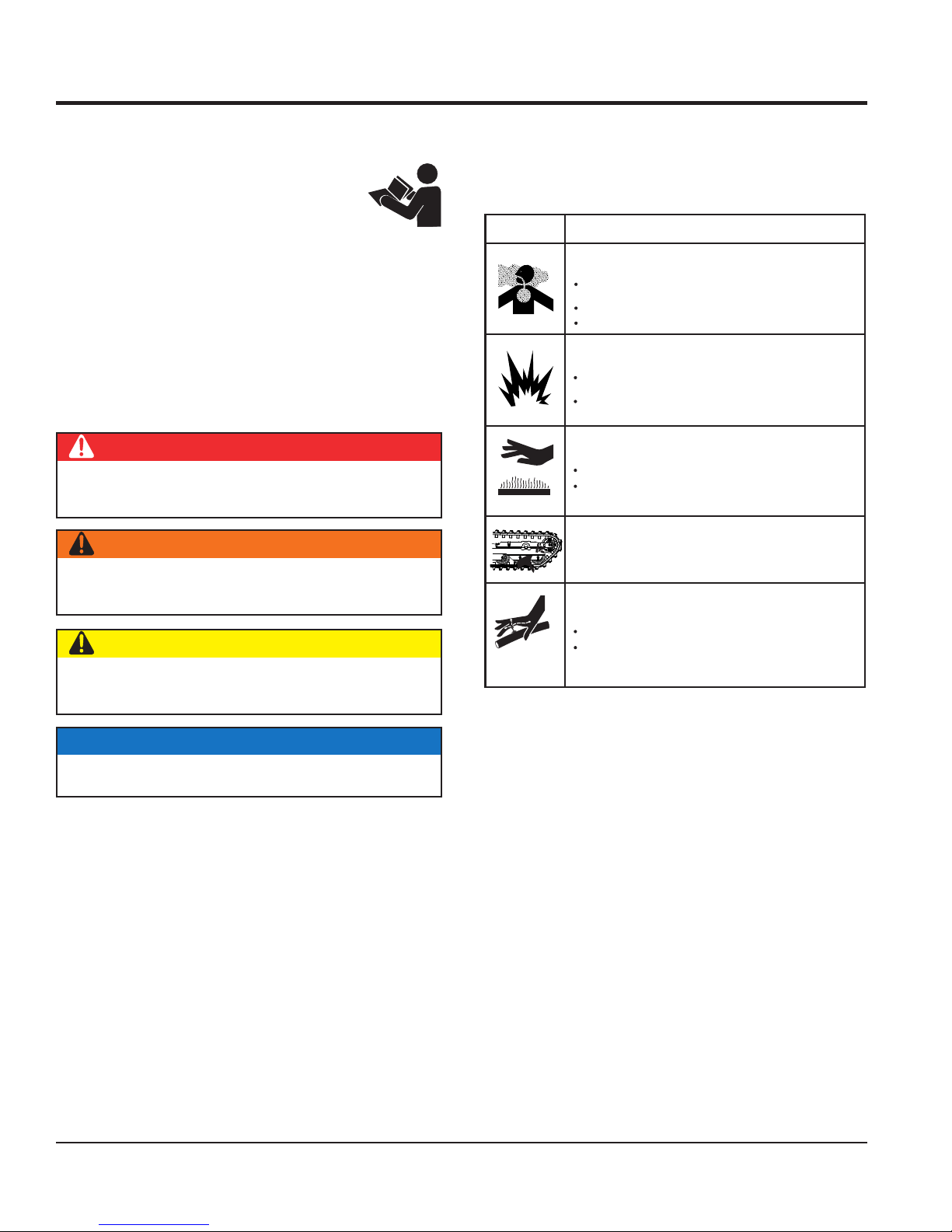
SYMBOL
Inhaling exhaust fumes can result in severe
injury or death.
Only operate equipment in well ventilated areas.
DO NOT inhale exhaust gases/fumes.
Gasoline fuel can cause fire or explosion. Stop
engine before refueling.
Keep cigarettes, sparks and flames away from hot
surfaces.
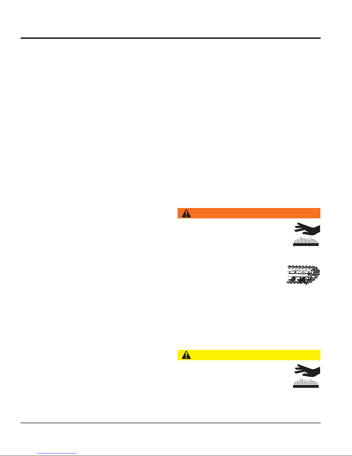
HOT PARTS can burn skin.
DO NOT touch hot parts. Allow machine a sufficient
amount of time to cool before performing maintenance.
Keep hands clear of rotating parts at all times.
HOT FLUID can burn skin.
DO NOT allow skin to come in contact with hot fluid.
Allow machine a sufficient amount of time to cool
before performing maintenance.
SAFETY HAZARD
WARNING
Lethal Exhaust Gas Hazard
WARNING
Explosive Fuel Hazard
CAUTION
Burn Hazard
WARNING
Rotating Parts Hazard
CAUTION
Burn Hazard
NOTICE
Addresses practices not related to personal injury.
PAGE 4 — WTB-16 TRACK-DRIVE POWER BUGGY • OPERATION MANUAL — REV. #1 (02/22/19)
Page 5

SAFETY INFORMATION
GENERAL SAFETY
NOTICE
This equipment should only be operated by trained and
Whenever necessary, replace nameplate, operation and
Manufacturer does not assume responsibility for any
accident due to equipment modifi cations. Unauthorized
use accessories or attachments that are not
recommended by Multiquip for this equipment. Damage
keep
Also, know the phone numbers
fi re department.
This information will be invaluable in the case of an
CAUTION
NEVER operate this equipment without proper protective
clothing, shatterproof glasses, respiratory protection,
hearing protection, steel-toed boots and other protective
devices required by the job or city and state regulations.
Avoid wearing jewelry or loose-fi tting clothes that may
snag on the controls or moving parts as this can cause
serious injury.
NEVER operate this equipment when not
feeling well due to fatigue, illness or when
under medication.
NEVER operate this equipment under the
infl uence of drugs or alcohol.
ALWAYS clear the work area of any debris, tools, etc.
that would constitute a hazard while the equipment is
in operation.
No one other than the operator is to be in the working
area when the equipment is in operation.
DO NOT use the equipment for any purpose other than
its intended purposes or applications.
qualifi ed personnel 18 years of age and older.
safety decals when they become diffi cult to read.
equipment modifi cation will void all warranties.
NEVER
to the equipment and/or injury to user may result.
ALWAYS know the location of the nearest
fi re extinguisher.
ALWAYS know the location of the nearest
fi rst aid kit.
ALWAYS know the location of the nearest phone or
a phone on the job site.
of the nearest ambulance, doctor and
emergency.
WTB-16 TRACK-DRIVE POWER BUGGY • OPERATION MANUAL — REV. #1 (02/22/19) — PAGE 5
Page 6

SAFETY INFORMATION
POWER BUGGY SAFETY
CAUTION
inspect the surface over which you will travel.
Look for holes, drop-offs and obstacles. Look for rough
and weak spots on docks, ramps or fl oor. Look for oil
spills, wet spots and slippery surfaces. Look for soft soil,
deep mud and standing water. Watch for anything that
might make you lose control or cause the power buggy
clear away trash and debris. Pick up anything
make sure aisles, ramps, doorways and
plan your work. Make sure you know where
you will make your pickups, dumps and turns. Before you
operate the power buggy on unsafe haul roads,
operate power buggy on excessive slopes with
a grade higher than 20% (12°), forward and backward.
unload material from the tub where the
longitudinal and lateral slope are present at the same
operate power buggy on extremely uneven
allow riders other than the operator on the
secure the step plate (platform) in the upright
position when using the power buggy over rough terrain.
stand on the power buggy step plate (platform)
when walking in rough terrain. Walk behind the power buggy.
DANGER
Engine fuel exhaust gases contain poisonous carbon
monoxide. This gas is colorless and odorless, and can
cause death if inhaled.
The engine of this equipment requires an adequate free
fl ow of cooling air. NEVER operate this equipment in any
enclosed or narrow area
where free fl ow of the air is
restricted. If the air fl ow is
restricted it will cause injury
to people and property and
serious damage to the
equipment or engine.
NEVER operate the equipment in an explosive
atmosphere or near combustible materials. An
explosion or fi re could result causing severe
bodily harm or even death.
WARNING
NEVER use your hand to fi nd hydraulic leaks.
Use a piece of wood or cardboard. Hydraulic
fl uid injected into the skin must be treated by
a knowledgeable physician immediately or
severe injury or death can occur.
Accidental starting can cause severe injury
or death. ALWAYS place the ON/OFF
switch in the OFF position.
ALWAYS
to tip over.
ALWAYS
that might puncture the rubber tracks.
WTB16
DANGEROUS
GAS FUMES
ALWAYS
passages are clear.
ALWAYS
take a load, know where you will place it.
NEVER operate the power
buggy facing backwards. In
a backwards position, the
operator cannot properly
activate the manual brake,
emergency switch, grip the
handles or steer the machine.
ALWAYS face in the direction
of the bucket.
DO NOT
load areas, or dump areas.
DO NOT
NEVER disconnect any emergency or safety devices.
These devices are intended for operator safety.
Disconnection of these devices can cause severe injury,
bodily harm or even death. Disconnection of any of these
devices will void all warranties.
NEVER approach power lines with any part of the
buggy unless all local, state/provincial and federal
(OSHA) required safety precautions have been taken.
Use extreme caution when approaching high-voltage
power lines.
PAGE 6 — WTB-16 TRACK-DRIVE POWER BUGGY • OPERATION MANUAL — REV. #1 (02/22/19)
DO NOT
time.
DO NOT traverse with the tub lifted.
DO NOT
surfaces.
NEVER
power buggy.
ALWAYS
DO NOT
Page 7

SAFETY INFORMATION
DO NOT touch, lean on or reach through the dump
DO NOT activate dump mechanism (tub) if buggy is
stand in front of or alongside the buggy when
block the power buggy with appropriate blocks
start
Ensure that both travel control levers work freely and
start engine
operate the power buggy with bad or worn
replace defective tracks with
make sure the hydraulic dumping mechanism
Avoid sudden stops, starts and changes in direction.
jerk the steering
attempt to work the control except from the
drive or tow the power buggy in traffi c or on
Fix damage to machine and replace any broken parts
The entire power buggy (tub, step plate, shroud, rubber
track, etc.) should be cleaned after every use. Make sure
there is no buildup of concrete, grease, oil or debris on
store equipment properly when it is not being
used. Equipment should be stored in a clean, dry location
out of the reach of children and unauthorized personnel.
position
mechanism or permit others to do so. NEVER climb on
the power buggy or dump mechanism.
DO NOT operate the power buggy at excessive speeds.
Reckless operation may cause accidents and severe
injury. Slow down when approaching people, wet areas,
and going up and down grades. It is the responsibility of
the operator to adjust speed, as necessary, depending
on the conditions of the road or path.
ALLOW extra time to stop when operating the power
buggy on wet surfaces or loosely graded materials.
DO NOT dump materials that are large and chunky.
These types of materials may shift causing the power
buggy to tip and throw the operator off the machine. The
power buggy is intended for dumping free-fl owing and
loose materials such as dry soil, slag, and wet concrete.
DO NOT dump materials from bucket while the power
buggy is moving.
For walk-behind operation, the operator platform must be
stowed and locked in the up position. The speed should
also be reduced to 3 mph (4.8 kph) or slower.
NOTICE
ALWAYS ensure power buggy is securely placed on
appropriate blocks or jack stands when performing
maintenance requires elevation of the buggy.
ALWAYS make sure the power buggy’s parking brake is
working properly. NEVER operate the power buggy with
a defective braking system.
Ensure brakes are applied when leaving or when using
on a slope.
When parking on a slope, position the power buggy at
a right angle to a slope. Ensure that the parking brake
is engaged and holds the power buggy safely in place
when parking on a slope.
When filling or dumping DO NOT exceed payload
capacity of power buggy.
ALWAYS be aware of traveling conditions. Reduce load
if necessary.
facing a downhill slope.
DO NOT
discharging a load.
ALWAYS
when leaving the power buggy parked on a slope.
To prevent unexpected loss of control, DO NOT
engine on a sloping surface.
return to their neutral position. DO NOT
unless the travel control linkage is working properly.
NEVER
rubber tracks. ALWAYS
new ones.
ALWAYS
of the tub is working properly.
Operate the controls smoothly. DO NOT
or any other controls.
NEVER
operator’s position.
NEVER
public roads.
ALWAYS keep the machine in proper running condition.
immediately.
the machine.
ALWAYS
ALWAYS place the fuel valve lever in the OFF
when the equipment is not in use.
WTB-16 TRACK-DRIVE POWER BUGGY • OPERATION MANUAL — REV. #1 (02/22/19) — PAGE 7
Page 8
SAFETY INFORMATION
RUBBER TRACK SAFETY
DO NOT burn used or damaged rubber tracks, as noxious
In the case of Iong-term storage, avoid direct sunlight and
If the unit will not be used for a long period of time, be sure
to rotate the rubber track at least once a month to avoid
When transporting the rubber track with a forklift, be aware
When replacing the rubber track, be sure the machine is
placed on secure level surface. The possibility exists of
) before
apply excessive force (prybar) when removing
operate the engine with heat shields or
shut down the engine before performing
remove the engine oil drain plug while the
engine is hot. Hot oil will gush out of the oil tank and
severely scald any persons in the general area of the
Make certain the operator knows how to and is capable
ALWAYS inspect the rubber track before each use. Be
sure to check the tension and maintain the prescribed
(regulated) tension.
ALWAYS drive slowly in areas where the road surface is
unstable such as forests, some construction sites, and/or
unpaved roads. High speed in these areas can result in
breakage of the rubber track.
Remove any foreign objects such as tree branches, leaves,
etc. caught between the frame and the rubber track, after
each operation.
lf foreign objects are not removed between the frame and
the rubber track, the gap between the rubber track and
the frame will shorten, and this can make the rubber track
more susceptible to cracks and wear.
Regularly inspect the condition of the sprocket, track
roller, idler, and the imbedded metal guide for abrasion.
Excessive or unusual abrasion or scarring can shorten
the life span of the rubber track.
Enlarge the turning radius when turning and changing
directions, in areas of high friction, such as asphalt, to
avoid premature breakage of the rubber track.
In cases where the job site location is far away, transport
the machine on a fl atbed truck or similar towing vehicle.
Continuous operation over long distances for an extended
period of time is not recommended.
Driving the rubber track through narrow passages on job
sites can fold the edges of the rubber track. Excessive
bending of the track can Iead to breakage.
When inspecting the rubber track or its components,
ensure that it is done on even ground and equipment has
been turned off.
fumes are emitted and can cause harm if inhaled.
keep indoors or under a protective cover.
stress being placed on one point continuously.
that the prongs can damage the track.
the machine rolling over if placed on an uneven surface.
ALWAYS shut down the equipment (OFF
removing or installing the rubber track.
DO NOT
the rubber track.
ENGINE SAFETY
WARNING
DO NOT place hands or fingers inside
engine compartment when engine is
running.
NEVER
guards removed.
Keep fi ngers, hands, hair and clothing
away from all moving parts to prevent
injury.
ALWAYS
service or maintenance.
DO NOT
When replacing worn or defective components, such
as sprocket, track roller, idler or imbedded metal guide,
replace with manufacturer’s recommended parts only.
ALWAYS use manufacturer’s recommended parts.
Unspecifi ed parts will shorten the life span of the rubber
track.
Use the rubber track for the prescribed purposes only.
PAGE 8 — WTB-16 TRACK-DRIVE POWER BUGGY • OPERATION MANUAL — REV. #1 (02/22/19)
power buggy.
CAUTION
NEVER touch the hot exhaust manifold,
muffl er or cylinder. Allow these parts to cool
before servicing equipment.
of turning the engine OFF in case of an emergency.
Page 9

SAFETY INFORMATION
NOTICE
FUEL SAFETY
BATTERY SAFETY
drop the battery. There is a possibility that the
keep the battery charged. If the battery is not
charge battery if frozen. Battery can explode.
When frozen, warm the battery to at least 61°F (16°C).
recharge the battery in a well-ventilated
environment to avoid the risk of a dangerous concentration
If the battery liquid (dilute sulfuric acid) comes into
, rinse eyes immediately with plenty
of water and contact the nearest doctor or hospital to
NEGATIVE battery terminal
keep battery cables in good working condition.
NEVER run engine without an air fi lter or with a dirty air
fi lter. Severe engine damage may occur. Service air fi lter
frequently to prevent engine malfunction.
NEVER tamper with the factory settings
of the engine or engine governor. Damage
to the engine or equipment can result
if operating in speed ranges above the
maximum allowable.
DO NOT start the engine near spilled fuel or combustible
fl uids. Fuel is extremely fl ammable and its vapors can
cause an explosion if ignited.
ALWAYS refuel in a well-ventilated area, away from
sparks and open fl ames.
ALWAYS use extreme caution when working with
fl ammable liquids.
DO NOT fi ll the fuel tank while the engine is running
or hot.
DANGER
DANGER
DO NOT
battery will explode.
DO NOT expose the battery to open fl ames,
sparks, cigarettes, etc. The battery contains
combustible gases and liquids. If these
gases and liquids come into contact with a
fl ame or spark, an explosion could occur.
WARNING
ALWAYS wear safety glasses when
handling the battery to avoid eye irritation.
The battery contains acids that can cause
injury to the eyes and skin.
Use well-insulated gloves when picking up
the battery.
ALWAYS
charged, combustible gas will build up.
DO NOT
DO NOT overfi ll tank and tighten fuel cap until you hear
clicking, since spilled fuel could ignite if it comes into
contact with hot engine parts or sparks from the ignition
system.
Store fuel in appropriate containers, in well-ventilated
areas and away from sparks and fl ames.
NEVER use fuel as a cleaning agent.
DO NOT smoke around or near the equipment.
Fire or explosion could result from fuel vapors
or if fuel is spilled on a hot engine.
DO NOT leave the power buggy in the vicinity of ovens,
furnaces or radiant heaters. Heat could raise the
pressure of the fuel so that vented gas could ignite.
ALWAYS
of combustible gases.
If the battery liquid (dilute sulfuric acid)
comes into contact with clothing or skin,
rinse skin or clothing immediately with
plenty of water.
contact with eyes
seek medical attention.
CAUTION
ALWAYS disconnect the
before performing service on the equipment.
ALWAYS
Repair or replace all worn cables.
WTB-16 TRACK-DRIVE POWER BUGGY • OPERATION MANUAL — REV. #1 (02/22/19) — PAGE 9
Page 10

SAFETY INFORMATION
LIFTING SAFETY
TRANSPORTING SAFETY
Tighten fuel tank cap securely and close fuel cock to
When transporting of the power buggy is required, place
the power buggy on a fl atbed truck or equivalent and tie
make sure all tie-downs and blocks are in
place and the bucket is completely lowered in the fl at
underneath wheel to prevent rolling.
When transporting the power buggy on a truck or trailer,
know the overall height to avoid contacting overhead
obstructions such as bridges and power lines. Check
position
CAUTION
NEVER allow any person or animal to stand underneath
the equipment while lifting.
NOTICE
When lifting of the power buggy is required, attach a strap
or chain of adequate lifting capacity to the lifting points
on the frame. Tub will have to be placed in the dump
position to gain access to the lifting points.
NEVER tip the engine to extreme angles during lifting as
it may cause oil to gravitate into the cylinder head, making
the engine start diffi cult.
DO NOT lift machine to unnecessary heights.
NEVER lift the machine while the tub is loaded with material.
NEVER lift the machine while the engine is running.
ALWAYS use ramps capable of supporting the weight
of the power buggy and the operator to load and unload
the power buggy.
NOTICE
ALWAYS shut down engine before transporting.
prevent fuel from spilling.
down securely.
ALWAYS
(horizontal) position and securely latched.
Place chock blocks
the truck and ramp capacities.
ALWAYS place the fuel valve lever in the OFF
before transporting.
PAGE 10 — WTB-16 TRACK-DRIVE POWER BUGGY • OPERATION MANUAL — REV. #1 (02/22/19)
Page 11

ENVIRONMENTAL SAFETY/DECOMMISSIONING
Decommissioning is a controlled process used to safely
retire a piece of equipment that is no longer serviceable.
If the equipment poses an unacceptable and unrepairable
safety risk due to wear or damage or is no longer cost
effective to maintain (beyond life-cycle reliability) and is to
be decommissioned (demolition and dismantlement), be
sure to follow rules below.
EMISSIONS INFORMATION
This equipment conforms with applicable Environmental
Protection Agency (EPA) and California Air Resources
The gasoline engine used in this equipment has been
designed to reduce harmful levels of carbon monoxide
(CO), hydrocarbons (HC) and nitrogen oxides (NOx)
Fuel and vapor recovery hoses, EPA certifi ed SAE J30R7
Tampering with or altering the emission control system may
increase emissions beyond the legal limit. Do not remove
Additionally, modifying the fuel system may adversely affect
evaporative emissions, resulting in fi nes or other penalties.
The emission control system is valid only for the United
States, its territories and commonwealths to include
The emission control label is an integral part of the emission
If a replacement emission label is needed, please contact
SAFETY INFORMATION
NOTICE
DO NOT pour waste or oil directly onto the ground, down
a drain or into any water source.
Contact your country’s Department of Public
Works or recycling agency in your area and
arrange for proper disposal of any electrical
components, waste or oil associated with
this equipment.
When the life cycle of this equipment is over, remove
battery (if equipped) and bring to appropriate facility for
lead reclamation. Use safety precautions when handling
batteries that contain sulfuric acid.
When the life cycle of this equipment is over, it is
recommended that the unit frame and all other metal
parts be sent to a recycling center.
NOTICE
Board (CARB) emission regulations.
contained in gasoline exhaust emissions.
Mandated Emission Components:
Engine, EPA certifi ed
Fuel cap, EPA certifi ed
or SAE J30R14T2
Charcoal canister, EPA certifi ed
Miscellaneous Parts Associated with Emission System:
Hose clamps and retainer brackets
Roll over valve vapor recovery valve
Steel fuel tank
Metal recycling involves the collection of metal from
discarded products and its transformation into raw
materials to use in manufacturing a new product.
Recyclers and manufacturers alike promote the process
of recycling metal. Using a metal recycling center
promotes energy cost savings.
or alter any part of the system.
Canada.
Emission Control Label
system and is strictly controlled by regulation(s).
The label must remain with the engine for its entire life.
your authorized engine distributor.
WTB-16 TRACK-DRIVE POWER BUGGY • OPERATION MANUAL — REV. #1 (02/22/19) — PAGE 11
Page 12

SPECIFICATIONS (TRACK BUGGY)
Table 1. Specifications (Track Buggy)
Model WTB-16
Maximum Weight Capacity 2,500 lb. (1,451 kg)
Operating Weight 1,896 lb. (677 kg)
Bucket/Tub Capacity 16 cu. ft. water level (.59 cu. yd.)
Bucket/Tub Material Polyethylene
Drive Hydrostatic
Speed Loaded Up to 4.7 mph (7.6 km/h)
Speed Transport Up to 5.1 mph (8.2 km/h)
Fuel Tank Capacity 5.0 gallons (20 liters)
Hydraulic Oil Tank Capacity 5.3 gallons (20.4 liters)
Hydraulic Oil Type Exxon/Mobil Nuto H68 or equivalent.
Hydraulic Filter, Return 10 micron
Brakes (Drive Track) Dynamic hydrostatic
Parking Brake (Drive Tracks) Hydraulic
Dump Control Hydraulic dump and return
Discharge Height 10.0 in. (254 mm)
Ground Clearance 6.0 in. (152 mm)
Gradeability 20% (12°)
12V BCI Group U1, 300 CCA @ 0°F
Battery (L × W × H)
Rubber Track
7.75 × 5.18 × 7.31 in.
(197 × 132 × 186 mm)
5.7 × 8.0
(145 × 203 × 483 mm)
PAGE 12 — WTB-16 TRACK-DRIVE POWER BUGGY • OPERATION MANUAL — REV. #1 (02/22/19)
Page 13

NOISE AND VIBRATION/ENGINE SPECIFICATIONS
Table 2. Noise and Vibration Emissions
Model
Guaranteed ISO 11201:2010 Based
Sound Pressure Level at Operator Station in dB(A)
Guaranteed ISO 3744:2010 Based
Sound Power Level in dB(A)
WTB-16
TBD
TBD
Whole Body Vibration per ISO 2631-1:1997+A1:2010 in m/s2 SA(8) TBD
NOTES:
1. Sound Pressure and Power Levels are “A” weighted measures per ISO 226:2003 (ANSI S1.4-1981). They are measured with the operating
conditions of the machine which generate the most repeatable but highest values of the sound levels. Under normal circumstances, the sound
level will vary depending on the condition of the material being worked upon.
2. The vibration level indicated is the vector sum of the RMS (Root Mean Square) values of amplitudes on each axis, standardized to an 8-hour
exposure period, and obtained using operating conditions of the machine that generate the most repeatable but highest values in accordance
with the applicable standards for the machine.
3. Per EU Directive 2002/44/EC, the daily exposure action value for whole body vibration is 0.5 m/s2 SA(8). The daily exposure limit value is
1.15 m/s2 SA(8).
Table 3. Engine Specifications
Model Honda GX690RHKXA Engine
Type
Air-cooled 4-stroke, overhead valve, 90° V-twin
2-cylinder, horizontal shaft, gasoline engine
Bore × Stroke 78 × 72 mm (3.1 × 2.8)
Piston Displacement 688 cc (41.9 cu. in)
Net Power Output 22 hp @ 3,600 rpm (16.5 kW)
Max. Torque 48.3 N.m (4.93 kgf.m 35.6 lbf.ft) @ 2,500 rpm
Cooling System Forced air
Air Cleaner Dual element
Engine Oil Capacity
SAE 10W-30 API Service Class SE or later
Fuel
Fuel Consumption 6 liters/hr. @ 3,600 rpm
Starting System Electric start/CDI type magneto ignition
Spark Plug Type ZFR5F NGK
Spark Plug Gap 0.70–0.80 mm (0.028–0.031 in.)
L × W × H 405 × 410 × 438 mm (15.9 × 16.1 × 17.2 in.)
Weight (Dry) 44.4 kg (97.8 lb.)
1.6 qt. (1.50 liters)
1.8 qt. (1.7 liters w/ oil filter replacement)
Unleaded gasoline
Octane rating of 86 or higher
Maximum 10% ethanol
See engine manual for further details.
WTB-16 TRACK-DRIVE POWER BUGGY • OPERATION MANUAL — REV. #1 (02/22/19) — PAGE 13
Page 14
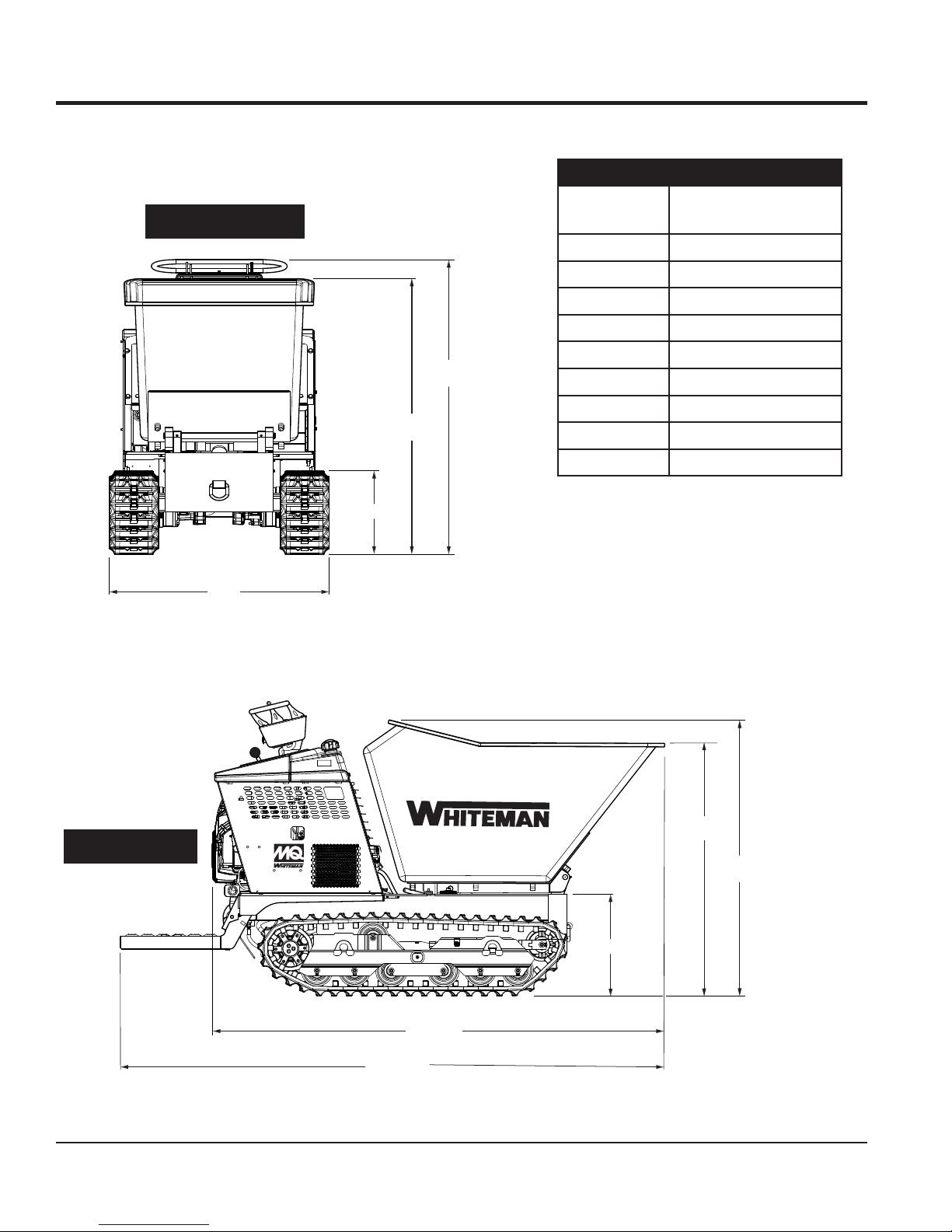
DIMENSIONS
Table 4. Dimensions
FRONT-VIEW
A
Reference
Letter
Dimension
in. (mm)
A 35.50 (902)
B 16.00 (406)
C 52.50 (1,334)
D 56.00 (1,422)
E 19.25 (489)
D
F 47.75 (1,213)
G 52.75 (1,340)
C
H 87.00 (2,210)
I 103.0 (2,616)
B
SIDE-VIEW
WTB16
PAGE 14 — WTB-16 TRACK-DRIVE POWER BUGGY • OPERATION MANUAL — REV. #1 (02/22/19)
F
G
E
H
I
Figure 1. WBT-16 Dimensions
Page 15

GENERAL INFORMATION
The MQ Whiteman Track Power Buggy, WTB-16 is intended
for the transportation of concrete, concrete spreading and
spot pouring. In addition, this power buggy is designed for
landscaping applications, material sub-base distribution,
job site cleanup and material transport.
The Power Buggy is equipped with a 10-inch dump height
which provides clearance and enables the operator to
maneuver over any form height. In addition, it has a unique
polyethylene tub design that reduces concrete splatter.
A low center of gravity has been incorporated into the
design which provides added safety when maneuvering the
buggy in tight areas. A 5.0-gallon (20-liter) fuel tank allows
for extended uninterrupted use. The maximum speed of the
power buggy is rated at 5.1 mph (8.2 km/h).
This buggy employs 16-inch-wide rubber tracks to traverse
the terrain. The tracks allow the buggy to travel over soft
ground such as sand and wet surfaces. The rubber track
design increases the overall traction of the buggy.
Hand and foot controls are provided for ease of dumping
and stopping of the power buggy. Multiple lift points have
been provided to allow for easy access of a forklift when
lifting is required.
The WTB-16 model is powered by a Honda GX690
air-cooled, gasoline engine rated at 22 hp at 3,600 rpm.
The operator controls the forward and reverse machine
travel by manually shifting the control levers which directs
the hydraulic fluid flow to the drive motors. The fluid flow
to the dump cylinder is controlled by a manually operated
control valve.
This hydraulic system incorporates a closed loop
configuration operating at a maximum of 4,300 psi (300 bar).
The hydraulic oil is filtered by a screen-type filter located in
the hydraulic tank, then double-filtered within the system
by a 10-micron cartridge spin-on return filter.
WARNING
All operators must have training before operating the
power buggy. For your safety, warnings are on the
machine and in this manual. Failure to obey these
warnings can cause severe injury or even death.
CAUTION
DO NOT attempt to operate the power
buggy until the Safety Information, General
Information, and Inspection sections of this
manual have been read and thoroughly
understood.
The engine drives a variable displacement hydrostatic axial
piston pump.
WTB-16 TRACK-DRIVE POWER BUGGY • OPERATION MANUAL — REV. #1 (02/22/19) — PAGE 15
Page 16

LIFTING AND TRANSPORTING
LIFTING AND TRANSPORTING THE TRACK BUGGY
The following procedure describes how to lift and transport
the track buggy.
WARNING
NEVER lift the track buggy with personnel standing
underneath the unit. ALWAYS clear the area of
bystanders. DO NOT lift to unnecessary heights or with
the tub loaded with material.
DUMP
A
FORKLIFT
POSITION
1. Place the tub/bucket in the dump position to gain
access to the two lifting points.
2. Attach a strap or chain of appropriate lifting capacity
to the lifting points as shown in Figure 2A.
3. Use a crane or forklift to hoist the track buggy onto a
flatbed truck for transporting.
4. Attach tie-down straps/chains to the tie-down points
on the track buggy as shown in Figure 2B.
WTB16
LIFTING
POINT (2)
FLATBED
TRUCK
TIE-DOWN
POINT (4)
B
PAGE 16 — WTB-16 TRACK-DRIVE POWER BUGGY • OPERATION MANUAL — REV. #1 (02/22/19)
Figure 2. Lifting the Track Buggy
Page 17

NOTES
WTB-16 TRACK-DRIVE POWER BUGGY • OPERATION MANUAL — REV. #1 (02/22/19) — PAGE 17
Page 18

COMPONENTS (BUGGY)
2
1
3
5
4
OFF
FUEL
9
6
7
8
ON
T
A
N
K
P
U
R
G
E
10
21
20
19
18
32
11
12
13
W
T
B
1
6
15
16
14
17
22
23
16
29
27
24
30
16
31
Figure 3. WTB-16 Power Buggy Components
PAGE 18 — WTB-16 TRACK-DRIVE POWER BUGGY • OPERATION MANUAL — REV. #1 (02/22/19)
16
30
28
25
26
20
Page 19

COMPONENTS (BUGGY)
1. Tub or Bucket — Used for the transportation of
material. Tub holds approximately 16 cubic feet
(0.59 cubic yards) of water.
2. Left Track Steering Lever — Controls left side of track
buggy. Reference Table 6 for directional positioning.
Allows the buggy to move in either a forward or reverse
direction.
3. Brake Lamp — When lit, indicates that the parking
brake is set (ON).
4. Oil Alert Lamp — When lit, indicates low engine oil.
This condition will cause the engine to shut down.
5. Right Track Steering Lever — Controls right side
of track buggy. Reference Table 6 for directional
positioning. Allows the buggy to move in either a
forward or reverse direction.
6. Handlebar — Grip this handlebar with both hands
when driving the buggy.
7. Brake Switch Knob — This switch sets and releases
the parking brake.
8. Emergency Stop Button — In the event of an
emergency, press this button to shut down the engine.
9. Fuel Valve Lever — When placed in the ON position
fuel will flow. OFF position stops fuel flow. ALWAYS
place this lever in the ON position when starting the
engine.
10. Charcoal Canister — Charcoal-activated system
that absorbs or traps fuel vapors. Basic component of
evaporative emissions control systems.
11. Documentation Canister — Store and maintain
Operation, Parts and Engine manuals in this container
at all times.
12. Relay/Fuse Panel — Contains one relay (parking
brake solenoid) and two fuses. The 5-amp fuse provides
protection for the parking brake relay. The 15-amp fuse
provides protection for the heat exchanger.
13. Parking Brake Solenoid — When activated, engages
the parking brake.
14. Engine — This machine uses an electric start, 20 hp,
Honda GX690 air-cooled gasoline engine.
15. Engine Oil Drain Plug — Remove plug to drain engine
crankcase oil.
16. Hydraulic Oil Access Port — There are five of these
ports on the machine. Remove the access cover to
clean out the hydraulic oil reservoir.
17. Dump Pedal — Use this pedal to place the tub in the
dump (vertical) position. Press the pedal a second
time to return the tub to the travel (horizontal) position.
18. Rubber Track — Inspect track daily for wear and
tear. DO NOT use the machine if the rubber track is
damaged.
19. Rubber Track Adjustment Bolt — Use this bolt to
adjust tension of the rubber track. Check tension daily.
20. Tie-Down Hook — When transporting of the buggy is
required, attach a strap to these tie-down points (4).
21. Towing Hook — Use this hook to tow the buggy if it
gets stuck on the job site. The machine must be placed
in free-wheel mode before towing, otherwise damage
to drive motors will occur. DO NOT tow on public roads.
22. Fuel Tank/Cap — Remove this cap to add fuel.
Tank holds approximately 5.0 U.S. gallons (20 liters).
DO NOT overfill. Tighten the cap until you hear ‘clicking.’
23. Dump Control Lever — Move this lever forward to
place the tub in the dump (vertical) position. Move the
lever backward to return the tub to the travel (horizontal)
position.
24. Operator Platform — When the buggy is in use, the
operator shall ALWAYS stand on this platform while
holding onto the handlebar.
25. Access Panel — Remove this panel to gain access
to the dump valve.
26. Hydraulic Oil Sight Gauge — Indicates the hydraulic
oil level.
27. Hydraulic Tank/Cap — Remove this cap to add
hydraulic oil. Tank holds approximately 5.3 U.S. gallons
(20.4 liters). DO NOT overfill.
28. Hydraulic Oil Filter — Spin-on type filter, 10-micron.
Filters out contaminants and debris.
29. Tandem Hydraulic Pump — Machine uses an axial
displacement piston pump and gear pump.
30. Lifting Hooks — When lifting of the buggy is required,
attach a strap/chain of adequate lifting capacity
(2,000 lb./907 kg) to these two lifting points.
31. Battery — Always use gloves and eye protection when
handling the battery.
32. Heat Exchanger — Provides cooling for the hydraulic
fluid. Transfers heat from the fluid.
WTB-16 TRACK-DRIVE POWER BUGGY • OPERATION MANUAL — REV. #1 (02/22/19) — PAGE 19
Page 20

BASIC ENGINE COMPONENTS
9
2
1
8
HONDA
GX690
3
4
5
14
10
13
10
7
Figure 4. Honda GX690 Engine Components
6
INITIAL SERVICING
The engine (Figure 4) must be checked for proper
lubrication and filled with fuel prior to operation. Refer to the
manufacturer’s engine manual for instructions and details
on operation and servicing.
1. Muffler — Used to reduce noise and emissions.
WARNING
Engine components can generate extreme
heat. To prevent burns, DO NOT touch
these areas while the engine is running
or immediately after operating. NEVER
operate the engine with the muffler removed.
2. Air Cleaner — Prevents dirt and other debris from
entering the fuel system. Unsnap the air filter cover to
gain access to the filter element.
3. Choke Knob — Used in the starting of a cold engine
or in cold weather conditions. The choke enriches the
fuel mixture.
4. Throttle Lever — Regulates engine speed.
5. Engine ON/OFF Switch — ‘ON’ position permits
engine star ting. ‘OFF’ position stops engine operation.
12
11
7. Oil Filter — Spin-on type, filters oil for contaminants.
8. Spark Plug — Provides spark to the ignition
system. Set the spark plug gap to 0.70–0.80 mm
(0.028–0.031 in.) Clean the spark plug once a week.
9. In-Line Fuel Filter — Filters fuel for contaminants.
10. Engine Lifting Hook — Attach a chain or rope to these
lifting hooks when lifting of the engine is required.
11. Engine Oil Drain Plug — Remove this plug to drain
engine crankcase oil.
12. Starter/Solenoid — Starts the engine when the
ignition key is rotated to the ‘ON’ position.
13. Engine Oil Dipstick — Remove to check the amount
and condition of oil in the crankcase.
14. Engine Oil Filler Cap — Remove to add engine oil.
NOTICE
Operating the engine without an air filter, with a damaged
air filter, or with a filter in need of replacement will allow
dirt to enter the engine, causing rapid engine wear.
6. Hour Meter — Indicates the number of hours the
machine has been in use.
PAGE 20 — WTB-16 TRACK-DRIVE POWER BUGGY • OPERATION MANUAL — REV. #1 (02/22/19)
Page 21

BEFORE STARTING
1. Read safety information at the beginning of the manual.
2. Clean the machine, removing dirt and dust—particularly
the engine cooling air inlet, carburetor and air cleaner.
3. Check the air filter for dirt and dust. If the air filter is
dirty, replace it with a new one.
INSPECTION
Figure 6. Engine Oil Level
4. Check the carburetor for external dirt and dust. Clean
with dry compressed air.
5. Check fastening nuts and bolts for tightness.
ENGINE OIL CHECK
1. To check the engine oil level, place the buggy on
secure, level ground with the engine stopped.
2. Remove the dipstick from its holder (Figure 5) and
wipe it clean.
OIL FILL
CAP
MOTOR OIL
DIPSTICK
6. When checking the engine oil, be sure to check if the oil
is clean. If the oil is not clean, drain the oil by removing
the oil drain plug, and refill with the specified amount
of oil as outlined in the Maintenance section of this
manual. Oil should be warm before draining.
Table 5. Oil Type
Season Temperature Oil Type
Summer 25°C or Higher SAE 10W-30
Spring/Fall 25°C~10°C SAE 10W-30/20
Winter 0°C or Lower SAE 10W-10
GASOLINE CHECK
DANGER
Motor fuels are highly flammable and can
be dangerous if mishandled. DO NOT
smoke while refueling. DO NOT attempt
to refuel the buggy if the engine is hot or
running.
1. Remove the fuel cap (Figure 7) located on top of the
fuel tank.
Figure 5. Engine Oil Dipstick Removal
3. Reinsert the dipstick back into its holder, then remove
it again. Check the oil level shown on the dipstick.
4. If the oil level is low, remove the oil fill cap (Figure 5)
and fill the engine crankcase with lubricating oil through
the oil filler hole. DO NOT overfill.
5. Make sure the buggy is level and verify that the oil level
is maintained between the two notches (Figure 6) as
shown on the dipstick. Reference Table 5 for proper
selection of engine oil.
WTB-16 TRACK-DRIVE POWER BUGGY • OPERATION MANUAL — REV. #1 (02/22/19) — PAGE 21
FUEL CAP
UNLEADED
GASOLINE
FUEL TANK
Figure 7. Fuel Tank
2. Visually inspect to see if the fuel level is low. If the fuel
level is low, replenish with unleaded fuel.
3. When refueling, be sure to use a strainer for filtration.
DO NOT top off fuel. Wipe up any spilled fuel
immediately. Tighten the fuel cap until it clicks.
Page 22

INSPECTION
BATTERY
This unit is of negative ground. DO NOT connect in reverse.
ALWAYS maintain battery fluid level between the specified
marks. Battery life will be shortened if the fluid levels are
not properly maintained. Add only distilled water when
replenishment is necessary. DO NOT overfill.
Check to see whether the battery cables are loose. Poor
contact may result in poor starting or malfunctions.
ALWAYS keep the terminals firmly tightened. Coat the
terminals with an approved battery terminal treatment
compound. Replace the battery with only the recommended
type battery. The battery type used in this power buggy is
BCI Group U1.
The battery is sufficiently charged if the specific gravity
of the battery fluid is 1.28 (at 68°F). If the specific gravity
should fall to 1.245 or lower, it indicates that the battery is
dead and needs to be recharged or replaced.
Before charging the battery with an external electric source,
be sure to disconnect the battery cables.
CAUTION
ALWAYS disconnect the negative terminal FIRST and
reconnect negative terminal LAST.
Battery Cable Installation
ALWAYS be sure the battery cables (Figure 8) are properly
connected to the battery terminals as shown below. The red
cable is connected to the positive terminal of the battery
and the black cable is connected to the negative terminal
of the battery.
NEGATIVE
When connecting the battery do the following:
1. NEVER connect the battery cables to the battery
terminals when the ignition is in the ON (start) position.
2. Place a small amount of battery terminal treatment
compound around both battery terminals. This will
ensure a good connection and will help prevent
corrosion around the battery terminals.
NOTICE
If the battery cable is connected incorrectly, electrical
damage to the power buggy will occur. Pay close attention
to the polarity of the battery when connecting the battery.
CAUTION
Inadequate battery connections may cause poor starting
of the power buggy and create other malfunctions.
RUBBER TRACK CHECK
The rubber tracks installed on the track buggy are very
important for its effective operation.
1. ALWAYS check the rubber tracks (Figure 9) for cuts
and abrasions.
RUBBER
TRACK
EXPOSED
STEEL CORD
MISSING
RUBBER
CRACKED
RUBBER
POSITIVE
Figure 8. Battery Connections
PAGE 22 — WTB-16 TRACK-DRIVE POWER BUGGY • OPERATION MANUAL — REV. #1 (02/22/19)
WORN
RUBBER
Figure 9. Rubber Track Inspection
2. DO NOT operate the track buggy if the rubber track is
deformed or damaged.
3. Check the tension of the rubber track every 50 hours.
Reference the Maintenance section in this manual on
how to check rubber track tension.
Page 23

LINKAGE CHECK
Check and make sure that all linkages within the buggy are
functioning correctly.
DUMP CYLINDER CHECK
1. Check the power buggy’s dump cylinder as outlined in
the maintenance section of this manual.
2. Make sure that both Zerk fittings for the dump cylinder
have been lubricated.
HYDRAULIC OIL CHECK
1. Visually read the hydraulic sight glass (Figure 10) to
see if the hydraulic oil level is low.
2. If the hydraulic oil is low, add enough hydraulic oil to
bring the oil level to a normal, safe operating level.
NORMAL
OPERATING
LEVEL (HOT)
INSPECTION
Figure 10. Hydraulic Sight Glass
WTB-16 TRACK-DRIVE POWER BUGGY • OPERATION MANUAL — REV. #1 (02/22/19) — PAGE 23
Page 24

CAUTION
SWITCH
(ST
DO NOT attempt to operate the power
buggy until the Safety Information, General
Information, and Inspection sections of this
manual have been read and thoroughly
understood.
1. Before attempting to start the power buggy, make
sure that the emergency stop switch (Figure 11)
is not pushed in. The power buggy will not start with
the emergency stop switch engaged. Pull the switch
outward when starting the engine.
CLOSED
(PULL)
CHOKE
KNOB
OPEN
(PUSH)
OPERATION
MAX.
MIN.
CHOKE
ENG
ON
START
OFF
1/10
HOUR
PULL
ART)
EMERGENCY
STOP
Figure 11. Kill Switch (OFF)
2. Place the fuel tank ON/OFF valve (Figure 12) in the ON
position.
Figure 12. Fuel Tank ON/OFF Valve (ON)
3. If starting a cold engine, pull the choke lever outward
(Figure 13) to the CLOSED position.
Figure 13. Engine Choke Lever
NOTICE
The CLOSED position of the choke lever enriches
the fuel mixture for starting a cold engine. The OPEN
position provides the correct fuel mixture for normal
operation after starting, and for restarting a warm
engine.
4. If starting a warm engine or the temperature is warm,
push the choke lever inward (Figure 13) to the OPEN
position.
5. Move the throttle lever halfway between the MIN. and
MAX. position (Figure 14) for starting.
MAX.
MIN.
CHOKE
ENG
ON
THROTTLE
START
OFF
LEVER
PAGE 24 — WTB-16 TRACK-DRIVE POWER BUGGY • OPERATION MANUAL — REV. #1 (02/22/19)
1/10
HOUR
Figure 14. Throttle Lever
Page 25

OPERATION
6. Place the ignition key (Figure 15 ) in the START position
and hold it until the engine starts. When the engine
starts, release the key, allowing it to return back to the
ON position.
MAX.
MIN.
CHOKE
ENG
ON
START
OFF
1/10
HOUR
Figure 15. Engine ON/OFF Switch (Start)
7. Run the engine for several minutes. Check for fuel
leaks and noises that could be associated with a loose
guard or cover.
8. Before operating, place the choke lever (Figure 13) in
the OPEN position.
TRAVELING
1. With the engine running, place the parking brake knob
(Figure 16) in the OFF position.
ON
4. Push both the left and right track levers forward slowly.
Notice that the track buggy begins to move in a forward
direction.
5. Practice maneuvering the track buggy using the
information listed in Table 6.
Table 6. Directional Positioning
TRACK LEVER
DIRECTION
Move LEFT Track
Lever Forward
Move LEFT Track
Lever Backward
Move RIGHT Track
Lever Forward
Move RIGHT Track
Lever Backward
Move BOTH Track
Levers Forward
Causes only the right-side of
the buggy to move forward.
Causes only the right-side of
the buggy to move backward.
Causes the buggy to move forward in a
straight line.
Causes the buggy to move backward in a
straight line.
RESULTS
Causes only the left-side of
the buggy to move forward.
Causes only the left-side of
the buggy to move backward.
OFF
Figure 16. Brake Knob (Off Position)
2. Verify that the parking brake release lamp is OFF.
K
I
R
N
A
P
G
Figure 17. Parking Brake Lamp (OFF)
3. Place the throttle lever (Figure 14) in the MAX. position.
WTB-16 TRACK-DRIVE POWER BUGGY • OPERATION MANUAL — REV. #1 (02/22/19) — PAGE 25
Move BOTH Track
Levers Backward
CAUTION
DO NOT steer the buggy left or right when traveling up
or down on a grade. Travel in a straight path.
CAUTION
Avoid sudden or quick turns. ALWAYS face the controls
when traveling.
Page 26

OPERATION
When traveling on a slope, it is necessary to determine
the grade of the path. The WTB-16 can travel up or down
a maximum grade of 20% (12°). DO NOT travel on steeper
slopes.
100
95
90
85
80
75
70
65
60
55
50
45
PERCENT GRADE
40
35
30
25
20
15
10
5
0
100
95
90
85
80
75
70
65
60
55
50
45
PERCENT GRADE
40
35
30
25
20
15
10
5
0
Figure 18. Determining Grade of Slope
20%
12°
10%
6°
35°
35°
100%
45°
70%
45°
70%
15
10
5
0
100%
10
5
0
25
20
25
DIRECTION
OF TRAVEL
20
15
DIRECTION
OF TRAVEL
45
40
35
30
WTB16
LEVEL BASE LINE
45
40
35
30
LEVEL BASE LINE
65
60
55
50
GRADE (DEGREES)
65
60
55
50
GRADE (DEGREES)
90
85
80
75
70
DISTANCE (D)
% GRADE = 100 (H¸D)
90
85
80
75
70
DISTANCE (D)
% GRADE = 100 (H¸D)
To determine the % grade of your path of travel, use the
formula and graphs as shown in Figure 18.
NOTICE
When going up or down a slope, always travel in the
forward direction (Figure 19).
HEIGHT (H)
HEIGHT (H)
WTB16
Figure 19. Slope Travel Direction
PAGE 26 — WTB-16 TRACK-DRIVE POWER BUGGY • OPERATION MANUAL — REV. #1 (02/22/19)
CORRECT
DIRECTION
FOR TRAVELING
DOWN A SLOPE
CORRECT
DIRECTION
FOR TRAVELING
UP A SLOPE
WTB16
Page 27

OPERATION
LIFT UP TO
TUB (BUCKET) DUMPING
WARNING
DO NOT activate the dump mechanism (tub/bucket) if
the buggy is facing downhill. The possibility exists of
the buggy tipping over causing equipment damage and
severe bodily harm.
NOTICE
Releasing either one (dump control lever or pedal)
before dump is completed will cause the tub to return
to the horizontal position.
TUB (BUCKET)
The hydraulic dump can be controlled by the hand dump
control lever or foot dump pedal.
1. To place the tub in the vertical position, press down
on the dump pedal (Figure 20A) or move the dump
control lever forward (Figure 20B). The tub will move to
the vertical position as long as pressure is continuously
applied to the dump pedal or the dump control lever is
held in the forward position.
2. To return the tub to the horizontal position, simply place
your foot underneath the dump pedal (Figure 20C) and
lift or pull back on the dump control lever (Figure 20D).
DUMP CONTROL LEVER
PUSH FORWARD TO DUMP
DUMP PEDAL
PRESS DOWN
TUB (BUCKET)
DUMP PEDAL
TO DUMP
WTB16
WTB16
TUB DUMP
METHOD 1
TUB RETURN
METHOD 1
A
C
TUB DUMP
METHOD 2
DUMP CONTROL LEVER
PULL BACKWARDS TO PLACE
TUB IN HORIZONTAL POSITION
TUB RETURN
METHOD 2
B
D
WTB-16 TRACK-DRIVE POWER BUGGY • OPERATION MANUAL — REV. #1 (02/22/19) — PAGE 27
Figure 20. Tub Dumping
Page 28

OPERATION
SWITCH
PUSH
SHUTDOWN (NORMAL)
Correct shutdown is important for safe operation. Follow
these general steps:
1. Come to a full stop.
2. Place the parking brake knob in the ON position
(brake set).
ON
OFF
Figure 21. Brake Knob (ON Position)
3. Verify that the parking brake lamp is lit (ON).
6. Place the fuel valve lever (Figure 23) in the OFF
position.
OFF
FUEL
OFF
Figure 23. Fuel Tank ON/OFF Valve (OFF)
7. Cycle the hydraulic controls to eliminate residual
pressure.
8. Remove the ignition key.
EMERGENCY SHUTDOWN
This power buggy is equipped with a safety kill switch. This
switch is located on the right side of the handlebar.
1. Push the EMERGENCY STOP switch (Figure 24).
K
I
R
A
P
Figure 22. Parking Brake Lamp (ON)
N
G
4. Place the throttle lever (Figure 14) in the slow position.
Idle the engine 3–5 minutes for gradual cooling.
5. Place the ignition switch key in the OFF position.
EMERGENCY
STOP
Figure 24. Emergency Stop Switch (Push)
PAGE 28 — WTB-16 TRACK-DRIVE POWER BUGGY • OPERATION MANUAL — REV. #1 (02/22/19)
Page 29

NOTES
WTB-16 TRACK-DRIVE POWER BUGGY • OPERATION MANUAL — REV. #1 (02/22/19) — PAGE 29
Page 30

Table 7. Engine Maintenance Schedule
MAINTENANCE
DESCRIPTION
(3)
OPERATION
BEFORE
EACH
USE
FIRST
MONTH OR
25 HRS.
EVERY 6
MONTHS
OR 100
HRS.
EVERY
YEAR
OR 300
HRS.
Check X
Engine Oil
Change X X
Engine Oil Filter Replace Every 100 hrs.
Check X
Air Cleaner
Clean X (1)
Change X X (*)
Check/Adjust X
Spark Plugs
Replace X
Cooling Fins Clean X
Fuel Filter Replace X (2)
Fuel Tube Check Every 2 years (replace if necessary) (2)
* - Replace the paper filter element only.
(1) Service more frequently when used in DUSTY areas.
EVERY 2
YEARS OR
500 HRS.
(2) These items should be serviced by your service dealer, unless you have the proper tools and are mechanically proficient.
Refer to the Honda Shop Manual for service procedures.
(3) For commercial use, log hours of operation to determine proper maintenance intervals.
Table 8. Power Buggy Maintenance Schedule
Periodic Maintenance Interval
Check Item OPERATION DAILY
Every
25 Hrs
Every
50 Hrs
Every
100 Hrs
Every 500
Hrs
Dump Cylinder Grease X
Swivel Wheels Shaft Grease X
Tub Bearing Pivot Block Grease X
Tub Clean X
Tub for Cracks/Deformations Check X
Rubber Track for Severe Cuts/Wear Check X
Hydraulic Oil Check X 1st time X
Hydraulic Oil Level Check/Replace X X
Parking Brake Check X
Fastners Check X
PAGE 30 — WTB-16 TRACK-DRIVE POWER BUGGY • OPERATION MANUAL — REV. #1 (02/22/19)
Page 31

MAINTENANCE
When performing any maintenance on the power buggy
or engine, follow all safety messages and rules for safe
operation stated at the beginning of this manual.
WARNING
Accidental starts can cause severe injury
or death.
ALWAYS place the ON/OFF switch in the
OFF position.
Disconnect and ground spark plug leads
and disconnect the negative battery cable
from the battery before servicing.
WARNING
Some maintenance operations may
require the engine to be running.
Ensure that the maintenance area
is well ventilated. Exhaust contains
poisonous carbon monoxide gas that
can cause unconsciousness and may
result in DEATH.
CAUTION
ALWAYS allow the engine to cool
before servicing. NEVER attempt any
maintenance on a hot engine.
AIR CLEANER (100 HOURS)
Thoroughly remove dirt and oil from the engine and
control area. Clean or replace the air cleaner elements as
necessary. Check and retighten all fasteners as necessary.
1. Release the latch tabs (Figure 25) on each side of the
air cleaner cover and remove the cover.
NOTICE
Operating the engine with loose or damaged air cleaner
components could allow unfiltered air into the engine,
causing premature wear and failure.
CAUTION
Wear protective equipment such as
approved safety glasses or face shields
and dust masks or respirators when
cleaning air filters with compressed air.
AIR CLEANER
COVER LATCHES
AIR CLEANER
FOAM FILTER
ELEMENT (OUTER)
WING NUT
PAPER FILTER
AIR CHAMBER
ELEMENT (INNER)
AIR CLEANER CASE
NOTICE
Operating the engine with a blocked filter screen,
dirty or plugged cooling fins, and/or cooling shrouds
removed will cause engine damage due to overheating.
DANGER
DO NOT use gasoline as a cleaning solvent to avoid
creating the risk of fire or an explosion.
WTB-16 TRACK-DRIVE POWER BUGGY • OPERATION MANUAL — REV. #1 (02/22/19) — PAGE 31
Figure 25. Air Filter Components
2. Remove the wing nut from the paper filter element.
3. Remove the outer foam filter.
4. Remove the inner paper filter.
5. Inspect both air filter elements and replace them if
necessary.
Page 32

MAINTENANCE
6. To clean the paper air filter (Figure 26), tap the filter
element several times on a hard surface to remove dirt,
or blow compressed air [not to exceed 30 psi (207 kPa,
2.1 kgf/cm²)] through the filter element from the air
cleaner case side.
Figure 26. Cleaning Inner Paper Filter
7. NEVER! try to brush off dirt; brushing will force dirt
into the fibers. If the paper element is excessively dirty,
replace the element.
8. Clean the foam air filter (Figure 27) element in warm,
soapy water, rinse and allow to dry thoroughly, or clean
with a nonflammable solvent and allow to dry. DO NOT
pour any type of oil into the foam element.
CHANGING ENGINE OIL (100 HOURS)
1. Drain the engine oil into a suitable container when the
oil is warm as shown in Figure 28.
Figure 28. Draining Engine Oil
2. Remove the oil drain bolt and sealing washer and allow
the oil to drain into a suitable container.
3. Reinstall the drain bolt with sealing washer and tighten
securely.
4. Replace engine oil with the recommended type oil as
listed in Table 5. For engine oil capacity, see Table 3.
DO NOT overfill.
OIL FILTER (200 HOURS)
Figure 27. Cleaning Foam Element
9. Wipe dirt from the inside of the air cleaner body and
cover using a moist cloth. Be careful not to let any
dirt or debris enter the air chamber that leads to the
carburetor.
10. Reinstall the foam air filter element to the air cleaner
cover, then reinstall the paper air filter element and
cover to the air cleaner case. Securely latch the hook
tabs onto the air cleaner cover.
1. Replace the engine oil filter (Figure 29) every 200 hours.
COAT RUBBER
SEAL WITH THIN
LAYER OF OIL
OIL FILTER
OIL FILTER
MOUNTING BASE
Figure 29. Oil Filter
OIL FILTER\
SOCKET
2. Use an oil filter socket and remove the oil filter.
3. Clean the area around the oil filter mounting base.
PAGE 32 — WTB-16 TRACK-DRIVE POWER BUGGY • OPERATION MANUAL — REV. #1 (02/22/19)
Page 33

MAINTENANCE
4. Coat the rubber seal (gasket) surface of the oil filter with
clean 15W-40 engine oil. See Figure 29.
5. Install the new oil filter first by hand until it makes
contact with the filter head surface. Tighten it another
3/4 turn using the filter socket. Tightening torque is
12 N·m (1.2 kgf·m, 9 lbf·ft).
IN-LINE FUEL FILTER (200 HOURS)
1. Place the fuel tank ON/OFF valve lever (Figure 30) in the
OFF position.
OFF
FUEL
OFF
Figure 30. Fuel Tank Valve Lever (OFF)
2. Replace the engine in-line fuel filter (Figure 31) every 200
hours. When replacing the filter pay close attention to the
orientation of the arrows.
Oil and Fuel Lines
Check the oil and fuel lines and connections regularly
for leaks or damage. Repair or replace as necessary.
Replace the oil and fuel lines every two years to maintain
the lines’ performance and flexibility.
SPARK PLUG ADJUSTMENT
1. Make sure the engine is cool before servicing the
spark plugs.
2. Disconnect the spark plug caps. Check for dirt and
remove any dirt from around the spark plug area.
3. Remove the spark plugs with a 5/8-inch spark plug
wrench.
4. If the spark plugs are damaged, the sealing washer
is in poor condition or the electrode is worn, replace
the spark plugs.
5. Measure the spark plug electrode gap (Figure 33) with
a wire-type feeler gauge. If needed, adjust the gap to
0.70–0.80 mm (0.028–0.031 in.) by carefully bending
the side electrode.
Figure 31. In-Line Fuel Filter
3. Return the fuel tank ON/OFF valve (Figure 32) to the
ON position.
Figure 32. Fuel Tank Valve Lever (ON)
Figure 33. Spark Plug Gap
6. Install the spark plug carefully, by hand, to avoid
cross-threading.
7. After the spark plug is seated, tighten with a 5/8-inch
spark plug wrench to compress the sealing washer.
8. When installing a new spark plug, tighten 1/2 turn, after
the spark plug seats, to compress the washer.
9. When reinstalling the original spark plug, tighten
1/8 to 1/4 turn after the spark plug seats to compress
the washer.
10. Reattach the spark plug caps.
WTB-16 TRACK-DRIVE POWER BUGGY • OPERATION MANUAL — REV. #1 (02/22/19) — PAGE 33
Page 34

ENGINE TUNE-UP
MAINTENANCE
See your engine manual for specific information on tuning up
your engine, checking and gapping the spark plugs, etc.
NOTICE
See the engine manual supplied with your machine
for an appropriate engine maintenance schedule and
a troubleshooting guide for problems.
ADDING HYDRAULIC OIL
1. Check the hydraulic oil level in the hydraulic oil tank
by reading the hydraulic oil sight glass (Figure 34)
mounted on the hydraulic oil tank.
NORMAL
OPERATING
LEVEL
TUB (BUCKET)
DUMP CONTROL
LEVER
DUMP PEDAL
Figure 35. Tub Dump Position
Hydraulic Oil Access
SUPPORT
ROD
5. Use the tub support rod to support the tub, then turn
the engine OFF.
6. Remove the two bolts that secure the access cover
(Figure 36) to the buggy frame.
Figure 34. Hydraulic Oil Sight Glass
2. If the hydraulic oil level is low, fill to the proper level with
EXXON/MOBIL NUTO H68 or equivalent.
3. To gain access to the hydraulic oil tank filler hole, the
tub (Figure 35) must be placed in the dump (vertical)
position.
4. Start the engine as outlined in the starting procedure,
then place the tub in the dumping position.
PAGE 34 — WTB-16 TRACK-DRIVE POWER BUGGY • OPERATION MANUAL — REV. #1 (02/22/19)
REMOVE BOLTS (2)
ACCESS
COVER
LATCH
Figure 36. Access Cover
7. Lift up on the access door and secure the latch
(Figure 36).
Page 35

MAINTENANCE
8. Remove the hydraulic oil filler cap (Figure 37) and add
hydraulic oil as required. Fill to the normal operating
mark as indicated on the hydraulic oil sight gauge.
HYDRAULIC
FLUID
HYDRAULIC TANK
FILLER NECK
HYDRAULIC OIL FILTER REPLACEMENT
1. Replace the hydraulic oil filter (Figure 38A) every 500
hours. Replace with only the recommended type filter.
FILTER
WRENCH
HYDRAULIC
OIL FILTER
A
REMOVE AND
DISCARD FILTER
Figure 37. Adding Hydraulic Oil
NOTICE
In climates where temperatures are below 35°F (1.6°C),
hard starting may occur. In these cases, the hydraulic oil
should be switched to a thinner 15weight hydraulic fluid.
9. Replace hydraulic oil after every 500 hours of operation.
The reservoir capacity is 5.3 gallons (20.4 liters). The
hydraulic oil filter should be changed each time the
hydraulic oil is changed.
B
COAT RUBBER
SEAL WITH THIN
LAYER OF OIL
Figure 38. Hydraulic Oil Filter
2. Using an oil filter wrench (Figure 38A), remove the
hydraulic oil filter.
3. Clean the area around the lubricating hydraulic oil
filter head.
4. Coat the rubber seal (gasket) surface of the oil
filter (Figure 38B) with clean 15W-40 engine oil.
5. Install the new hydraulic oil filter first by hand until it
makes contact with the filter head surface. Tighten it
another 3/4 turn using the filter wrench.
INSTALL
NEW HYDRAULIC
OIL FILTER
WTB-16 TRACK-DRIVE POWER BUGGY • OPERATION MANUAL — REV. #1 (02/22/19) — PAGE 35
6. Run the system and check for leaks.
Page 36

HYDRAULIC DRIVE MOTORS
The hydraulic drive motors (Figure 39) are extremely
reliable and will not need maintenance or repair under
normal conditions.
HYDRAULIC DRIVE MOTOR
LEFT
HYDRAULIC
DRIVE MOTOR
MAINTENANCE
GREASE
GUN
ZERK FITTING
RIGHT
HYDRAULIC
DRIVE MOTOR
Figure 39. Hydraulic Drive Motor
NOTICE
Contact Multiquip’s Service Department should any
problems develop with the hydraulic drive motors.
CHASSIS LUBRICATION
This power buggy is equipped with six Zerk fittings
(Figure 40). Lubricate these Zerk fittings each day before
operating the buggy.
A
B
TUB
BEARING
PIVOT
BLOCK
DUMP
CYLINDER
GREASE
GUN
C
DUMP
CYLINDER
(TOP)
DUMP
CYLINDER
(BOTTOM)
SWIVEL
WHEELS
1. Lubricate with high-grade chassis lubricant at all
lubricating points listed below:
• Tub Bearing Pivot Blocks (Underside of Tub) — Two
Zerk fittings on both sides of the machine (Figure 40A).
• Dump Cylinder Pivots — Two Zerk fittings, top and
bottom of dump cylinder (Figure 40B).
• Swivel Wheels — Two Zerk fittings, both sides of
machine (Figure 40C).
PAGE 36 — WTB-16 TRACK-DRIVE POWER BUGGY • OPERATION MANUAL — REV. #1 (02/22/19)
GREASE
GUN
Figure 40. Lubrication Points
Page 37

MAINTENANCE
PRESSURE TESTING
To ensure optimal performance of your track buggy,
hydraulic pressure checks should be performed periodically.
The following hydraulic pressure checks should be checked:
Dump Valve Pressure
Charge Pressure (Return)
Left-Side Hydraulic Motor (Forward/Reverse)
Right-Side Hydraulic Motor (Forward/Reverse)
Multiquip offers a ‘Special Test Pressure Gauge Kit.’ When
installed, the disconnection of hydraulic hoses is no longer
required.
Simply unscrew the protective cap and insert the pressure
gauge into the test port. Installation of the test pressure kit
makes pressure testing quick and easy.
Charge Pressure (Return)
1. To gain access to the hydraulic oil filter, place the tub
in the dump (vertical) position.
2. Lift up on the access panel to gain entry to the pump
and hydraulic compartment area. Secure the access
panel with the latch.
3. Remove the hydraulic hose connected to the 90° fitting
from port A on the dump valve (Figure 42A).
4. Insert the T-fitting and gauge into the 90° fitting.
5. Start the engine. Prior to testing, warm the hydraulic
system oil until it reaches 100°F.
6. Stop the engine.
7. Reconnect the hydraulic hose back onto the 90° fitting,
port A (top).
8. Remove the hydraulic hose connected to the 90° fitting
(Figure 42B) from port B (bottom) on the hydraulic
pump. This port is for the left-side hydraulic drive motor
forward direction.
9. Insert the test gauge into the 90° fitting port B (bottom).
10. Start the engine and run at high speed. The test gauge
should read 4,350 psi (300 bar).
11. Stop the engine.
12. Reconnect the hydraulic hose back onto the 90° fitting,
port B (bottom).
13. Repeat this procedure for the right-side hydraulic drive
motor (hydraulic pump 2).
Dump Valve Pressure
1. To gain access to the dump valve, remove the three
screws that secure the access cover to the panel.
RETAINING
SCREWS (3)
REMOVE
DUMP VALVE
ACCESS
COVER
6. Increase engine RPMs to high speed. The test gauge
should read 215–216 psi (14–15 bar).
Hydraulic Drive Motors
1. Place the parking knob in the ON position (brake set).
2. Locate the left and right track hydraulic drive motors
at the bottom front of the machine.
3. Remove the hydraulic hose connected to the 90° fitting
(Figure 42B) from port A (top) on the hydraulic pump
(pump 1). This port is for the left-side hydraulic drive
motor reverse direction. Refer to the hydraulic diagram.
4. Insert the test gauge into the 90° fitting (top).
5. Start the engine and run at high speed. Momentarily
push the travel lever to full travel for a few seconds, just
long enough to read the test gauge. The value should
read 4,350 psi (300 bar).
WTB-16 TRACK-DRIVE POWER BUGGY • OPERATION MANUAL — REV. #1 (02/22/19) — PAGE 37
Figure 41. Access Cover
2. Remove the hydraulic hose connected to the 90° fitting
from port A on the dump valve (Figure 42C).
3. Insert the T-fitting and gauge into the 90° fitting.
4. Start the engine and place the dump lever in the dump
position. The tub should be in the vertical position. The
test gauge should read 1,500 psi (110 bar).
5. Stop the engine and reconnect the hydraulic hose back
onto the 90° fitting, port A.
Page 38

MAINTENANCE
1,500 PSI
(110 BAR)
PORT A
90°FITTING
DISCONNECT
OPTIONAL
FITTING
DUMP
VALVE
PRESSURE
HOSE
A
TEST
GAUGE
1
215–216 PSI
(14–15 BAR)
PORT A
90° FITTING
HYDRAULIC
OIL FILTER
CHARGE
PRESSURE
OPTIONAL
DISCONNECT
HOSE
FITTING
1
C
DISCONNECT
HOSES
4 PLACES
4
4,350 PSI
(300 BAR)
NOTES:
1
2
3
4
5
OPTIONAL
1
FITTING
4 PLACES
INCLUDED WITH SPECIAL TEST GAUGE KIT
REFERENCE PARTS MANUAL TO ORDER
TOP 90° FITTING LEFT-SIDE REVERSE (PUMP 1)
BOTTOM 45° FITTING LEFT-SIDE REVERSE (PUMP 1)
TOP 45° FITTING RIGHT-SIDE REVERSE (PUMP 2)
BOTTOM 45° FITTING RIGHT-SIDE REVERSE (PUMP 2)
2
3
PRESSURE
5
MOTOR
DRIVE
Figure 42. Test Port Connections
PAGE 38 — WTB-16 TRACK-DRIVE POWER BUGGY • OPERATION MANUAL — REV. #1 (02/22/19)
B
Page 39

MAINTENANCE
RUBBER TRACK
Rubber Track Removal/Installation
1. Lift the track buggy slightly off the ground.
2. Using a 1-1/8" socket (Figure 43A), loosen the
adjustment bolt until there is sufficient slack in the
rubber track.
3. Remove the track from the adjustment wheel
(Figure 43B).
4. Push the track backwards and remove from the rear
sprocket, then pull outward (Figure 43C) and remove
the rubber track.
TURN
COUNTER
CLOCKWISE
TO LOOSEN
5. Contact your Department of Public Works or recycling
agency in your area to arrange for proper disposal of
the rubber track.
6. To install a new rubber track, align with the front
sprocket and adjustment wheel.
7. Once the rubber track has been properly aligned and
placed onto the sprocket, tighten the adjustment bolt
(Figure 43D) until there is 0.4–0.6 in. (10–15 mm)
tension (Figure 43E) between the center track roller
and the rubber track.
NOTICE
For prolonged use and proper care of the rubber tracks,
reference the Safety Information section in this manual.
A
LIFTING
0.4 - 0.6 in.
(10 - 15 mm)
E
PULL
OUTWARD
TURN
CLOCKWISE
TO TIGHTEN
D
PULL
UPWARD
C
PUSH
INWARD
B
ADJ
WHEEL
Figure 43. Removing Installing Rubber Track
WTB-16 TRACK-DRIVE POWER BUGGY • OPERATION MANUAL — REV. #1 (02/22/19) — PAGE 39
Page 40

LONG-TERM STORAGE/TROUBLESHOOTING (TRACK BUGGY)
LONG-TERM STORAGE
Store the unit with a protective cover in a moisture- and
dust-free location out of direct sunlight.
Drain the fuel tank completely, or add STA-BIL to the fuel.
Rotate the rubber track at least once a month to avoid
Remove the spark plug and pour a few drops of motor
fatigue placed on one point continuously.
oil into the cylinder. Crank the engine 3–4 times so that
oil reaches all internal parts.
Clean the exterior with a cloth soaked in clean oil.
Remove the battery.
CAUTION
NEVER store the power buggy with fuel in the tank for
any extended period of time. ALWAYS clean up spilled
fuel immediately.
Troubleshooting (Track Buggy)
Symptom Possible Problem Solution
Loss of power Engine rpm too low? Adjust engine speed.
Rubber track damaged or loose skipping
sprocket teeth?
Loss of travel
Loss of travel speed
Machine drifts either to the left or right Mechanical travel levers out of adjustment? Adjust levers to neutral position.
Diffi cult to steer or sluggish movement Defective or worn rubber tracks?
Machine does not move or only in one
direction
System operating hot
Slow dumping
Parking brake will not hold Defective parking brake solenoid? Check 5 amp fuse or replace solenoid.
Engine will not start
Parking brake engaged (ON)? Place parking brake knob in OFF position.
System jerky when levers are activated? Air in hydraulic system.
Clogged hydraulic oil fi lter? Replace the fi lter cartridge.
Travel activation control levers out of
adjustment?
Damaged hydraulic pump or motor?
Rubber track is damaged or loose?
Broken or damaged travel lever linkage? Inspect connector ball joints and linkage.
A foreign object is wedged between track and
frame?
Hydraulic oil level is low? Check hydraulic oil level add oil if necessary
Defective heat exchanger?
Low engine speed? Check engine speed adjust if necessary
Dump cylinder may be internally bypassing oil? Inspect for pressure leakage.
Dump valve low pressure?
Low on fuel or empty tank? Add fuel.
Defective emergency stop switch? Check or replace emergency stop switch.
Fuel shutoff valve is closed? Open fuel shutoff valve.
Dead battery? Verify battery and alternator charge condition.
Blown Control Box 30 amp fuse? Check or replace fuse.
Defective diode? Check or replace diode.
Inspect rubber track if necessary adjust
tension or replace.
Inspect levers for full pump stroke.
Inspect rubber track if necessary adjust
tension or replace.
Inspect for proper hydraulic pressure
4300 psi (300 bar).
Inspect rubber track if necessary adjust
tension or replace.
Remove object or debris.
Check 15 amp fuse or replace heat
exchanger.
Check dump valve relief pressure 1500 psi
(110 bar).
PAGE 40 — WTB-16 TRACK-DRIVE POWER BUGGY • OPERATION MANUAL — REV. #1 (02/22/19)
Page 41

Symptom Possible Problem Solution
Diffi cult to start, fuel is available, but no spark at
spark plug.
Diffi cult to start, fuel is available, and spark is
present at the spark plug.
Diffi cult to start, fuel is available, spark is
present and compression is normal.
Diffi cult to start, fuel is available, spark is
present and compression is low.
No fuel present at carburetor.
TROUBLESHOOTING (ENGINE)
Troubleshooting (Engine)
Spark plug bridging? Check gap, insulation or replace spark plug.
Carbon deposit on spark plug? Clean or replace spark plug.
Short circuit due to defi cient spark plug
insulation?
Improper spark plug gap? Set to proper gap.
Spark plug is red? Check transistor ignition unit.
Spark plug is bluish white?
No spark present at tip of spark plug?
No oil? Add oil as required.
Oil pressure alarm lamp blinks upon starting? (if
applicable)
ON/OFF switch is shorted? Check switch wiring, replace switch.
Ignition coil defective? Replace ignition coil.
Improper spark gap, points dirty? Set correct spark gap and clean points.
Condenser insulation worn or short circuiting? Replace condenser.
Spark plug wire broken or short circuiting? Replace defective spark plug wiring.
Wrong fuel type?
Water or dust in fuel system? Flush fuel system.
Air cleaner dirty? Clean or replace air cleaner.
Choke open? Close choke.
Suction/exhaust valve stuck or protruded? Reseat valves.
Piston ring and/or cylinder worn? Replace piston rings and/or piston.
Cylinder head and/or spark plug not tightened
properly?
Head gasket and/or spark plug gasket damaged? Replace head and spark plug gaskets.
No fuel in fuel tank? Fill with correct type of fuel.
Fuel cock does not open properly?
Fuel fi lter/lines clogged? Replace fuel fi lter.
Fuel tank cap breather hole clogged? Clean or replace fuel tank cap.
Air in fuel line? Bleed fuel line.
Check spark plug insulation, replace if worn.
If insuffi cient compression, repair or replace
engine. If injected air leaking, correct leak. If
carburetor jets clogged, clean carburetor.
Check if transistor ignition unit is broken, and
replace defective unit. Check if voltage cord
cracked or broken and replace. Check if spark
plug if fouled and replace.
Check automatic shutdown circuit, "oil sensor".
(if applicable)
Flush fuel system, replace with correct type of
fuel.
Torque cylinder head bolts and spark plug.
Apply lubricant to loosen fuel cock lever,
replace if necessary.
WTB-16 TRACK-DRIVE POWER BUGGY • OPERATION MANUAL — REV. #1 (02/22/19) — PAGE 41
Page 42

Symptom Possible Problem Solution
Weak in power, compression is proper and
does not misfi re.
Weak in power, compression is proper but
misfi res.
Engine overheats
Rotational speed fl uctuates.
Recoil starter malfunctions. (if applicable)
Starter malfunctions.
Burns too much fuel.
Exhaust color is continuously "white".
Exhaust color is continuously "black".
Will not start, no power with key "ON". (if
applicable)
TROUBLESHOOTING (ENGINE)
Troubleshooting (Engine) - continued
Air cleaner dirty? Clean or replace air cleaner.
Improper level in carburetor? Check fl oat adjustment, rebuild carburetor.
Defective spark plug? Clean or replace spark plug.
Improper spark plug? Set to proper gap.
Water in fuel system?
Dirty spark plug? Clean or replace spark plug.
Ignition coil defective? Replace ignition coil.
Wrong type of fuel? Replace with correct type of fuel.
Cooling fi ns dirty? Clean cooling fi ns.
Intake air restricted?
Oil level too low or too high? Adjust oil to proper level.
Governor adjusted incorrectly? Adjust governor.
Governor spring defective? Replace governor spring.
Fuel fl ow restricted? Check entire fuel system for leaks or clogs.
Recoil mechanism clogged with dust and dirt? Clean recoil assembly with soap and water.
Spiral spring loose? Replace spiral spring.
Loose, damaged wiring?
Battery insuffi ciently charged? Recharge or replace battery.
Starter damaged or internally shorted? Replace starter.
Over-accumulation of exhaust products?
Wrong spark plug?
Lubricating oil is wrong viscosity? Replace lubricating oil with correct viscosity.
Worn rings? Replace rings.
Air cleaner clogged? Clean or replace air cleaner.
Choke valve set to incorrect position? Adjust choke valve to correct position.
Carburetor defective, seal on carburetor
broken?
Poor carburetor adjustment, engine runs too
rich?
ON/OFF device not activated ON? Turn on ON/OFF device.
Battery disconnected or discharged?
Ignition switch/wiring defective? Replace ignition switch. Check wiring.
Flush fuel system and replace with correct
type of fuel.
Clear intake of dirt and debris. Replace air
cleaner elements as necessary.
Ensure tight, clean connections on battery
and starter.
Check and clean valves. Check muffl er and
replace if necessary.
Replace spark plug with manufacturer's
suggested type.
Replace carburetor or seal.
Adjust carburetor.
Check cable connections. Charge or replace
battery
PAGE 42 — WTB-16 TRACK-DRIVE POWER BUGGY • OPERATION MANUAL — REV. #1 (02/22/19)
Page 43

J
DUMP
CYLINDER
DUMP
VALVE
K
HYDRAULIC SYSTEM DIAGRAM
B
T
P
A
70 bar
L
DUMP
VALVE
ADJ.
BLUE CIRCLE WITH WHITE LETTERING
DENOTES COMPONENT LOCATION.
REFERENCE HYDRAULIC HOSE LOCATOR
COMPONENT DRAWINGS.
1
NOTE:
E
DRIVE
RIGHT
MOTOR
2
L
1
R
Paux
GEAR
PUMP
F
SUCTION AUX.
H
FILTER
CHARGE
10 micron
Beta10 > 100
I
RIGHT TRACK
X
FORWARD
300 bar
A2
C
BRAKE
PARKING
SOLENOID
PUMP
B
RIGHT-SIDE
X
R
1
LEFT TRACK
LEFT
DRIVE
MOTOR
D
L
2
G
FORWARD
HYD. DRIVE
300 bar
A1
PUMP
LEFT-SIDE
HYD. DRIVE
A
14 bar
300 bar
300 bar
B2
S
T
P
G
COOLER
HYD. OIL
****
T12
T22
1.5 bar
B1
T11
T21
TANK
HYDRAULIC OIL
Suction Strainer
100 micron
WTB-16 TRACK-DRIVE POWER BUGGY • OPERATION MANUAL — REV. #1 (02/22/19) — PAGE 43
3600 RPM
Page 44

LEFT-SIDE HYD.
A
DRIVE PUMP
HYDRAULIC HOSE CONNECTIONS 1
HYDRAULIC OIL
RESERVOIR
“MAIN FRAME”
RIGHT-SIDE HYD.
B
DRIVE PUMP
TANDEM
HYDRAULIC DRIVE
PUMP
LEFT-SIDE HYD.
D
DRIVE MOTOR
1
RIGHT SIDE HYD.
DRIVE MOTOR
PARKING
BRAKE SOLENOID
C
E
NOTE:
HOSE COLORS SHOWN FOR CLARITY ONLY.
1
PAGE 44 — WTB-16 TRACK-DRIVE POWER BUGGY • OPERATION MANUAL — REV. #1 (02/22/19)
Page 45

HYDRAULIC OIL
COOLER
G
HYDRAULIC HOSE CONNECTIONS 2
HYDRAULIC OIL
RETURN FILTER
10 MICRON
H
GEAR PUMP
F
TO
DUMP VALVE
HYDRAULIC
OIL TANK
I
WTB-16 TRACK-DRIVE POWER BUGGY • OPERATION MANUAL — REV. #1 (02/22/19) — PAGE 45
Page 46

HYDRAULIC HOSE CONNECTIONS 3
DUMP
VALVE
CAP
DUMP VALVE
ADJUSTMENT
SCREW
L
GEAR PUMP
F
DUMP
CYLINDER
DUMP
VALVE
K
J
PAGE 46 — WTB-16 TRACK-DRIVE POWER BUGGY • OPERATION MANUAL — REV. #1 (02/22/19)
Page 47

ELECTRICAL COMPONENT LOCATOR DIAGRAM
5
BLK/YEL
WIRE
6
7
MAX.
1
4
L Y
B
B/Y
MIN.
CHOKE
ENG
START
ON
OFF
1/10
HOUR
8
9
10
2
11
3
CONTROL BOX
REAR COVER
68 MM
SPECIAL SCREW
12
30 AMP
FUSE
FUSE COVER
13
17
14
15
OIL FILTER
WTB16
16
19
18
16
20
21
23
22
24
WTB-16 TRACK-DRIVE POWER BUGGY • OPERATION MANUAL — REV. #1 (02/22/19) — PAGE 47
Page 48

1
ENGINE
GND. POINT
2
16
COMBINATION SWITCH
CONTINUITY
GND
IG
BAT LO ST
OFF
ON
ST
1
CONTROL BOX
B/W
ST
B/Y
LO
IGNITION
SWITCH
W
G
BLK
BATT.
GND.
IGN.
3
CONTROL BOX
GND. POINT
HOUR
METER
30 AMP.
FUSE
12
VOLTAGE
REGULATOR
RECTIFER
GRN
G (GRN)
GR
GR
W/Bu
B/Y
W
B
Y (YEL)
BU (BLUE)
B/Y (BLK/YEL)
P1
J1
GRAY
GRAY
BLK/YEL
BLK
ENGINE
GND. POINT
+12VDC WHT
NC
WHT
CONTROL BOX
+12VDC
SIDE
HONDA HARNESS
BU
B/Y
BK
FEMALE
BLK (A)
YEL
5
GR
GR
ELECTRICAL WIRING DIAGRAM
ENGINE
H
BU
Y
+12VDC BLK/YEL
B/Y
BK
EMERGENCY
STOP SWITCH
21
ENGINE
GND. POINT
SPLICE
11
14
SPLICE
SIDE
2 1
BLK (B)
YEL
NC
21
NC
BLK (A)
SPLICE
B/Y
POSITIVE
BATTERY
B/Y
FUEL CUT-OFF
SOLENOID
BLK/WHT
WHT
+12VDC
RED
STARTER
MOTOR
SOLENOID
NEGATIVE
24
CHASSIS
GND.
GND. SIGNAL BLK
BLK/YEL
6
8
M
CHASSIS
GND.
IGN.
START
CHASSIS
GND.
10
B/Y
9
4 7
Y
MALE
BLK (B)
30 87A
17 AMP
CHARGE COIL
BR
13
GND. BLUE
85
K1
HEAT EXCHANGER
RELAY COIL
ENERGIZED
DURING CRANKING
CYCLE ONLY
86
+12VDC RED
DIODE
PAGE 48 — WTB-16 TRACK-DRIVE POWER BUGGY • OPERATION MANUAL — REV. #1 (02/22/19)
SPLICE
SPLICE
BLK/YEL
BLK
+12VDC YEL
GND. BLUE
Page 49

ELECTRICAL WIRING DIAGRAM
BU
Y
B
PARKING BRAKE
SWITCH
20
NC
BR
NO
BR
5 AMP
15
FUSE
BR
BR
Y
UNIT
IGNITION
COIL (RIGHT)
OIL LEVEL
SWITCH
17
CHASSIS
GND.
PARKING BRAKE
LAMP
BLK
OIL ALERT
LAMP
BLK
+12VDC YEL
GND. BLUE
18
WHT
Y
B
UNIT
GND. FROM
19
EMERG. STOP
WHT
BLK
BR
PURPLE
IGNITION
COIL (LEFT)
PARKING BRAKE
SOLENOID
22
1
CHASSIS
GND.
NOTE:
23
BLUE CIRCLE WITH WHITE LETTERING
DENOTES COMPONENT LOCATION.
1
REFERENCE ELECTRICAL LOCATOR
COMPONENT DRAWING.
WTB-16 TRACK-DRIVE POWER BUGGY • OPERATION MANUAL — REV. #1 (02/22/19) — PAGE 49
Page 50

OPERATION MANUAL
HERE’S HOW TO GET HELP
© COPYRIGHT 2019, MULTIQUIP INC.
Multiquip Inc
the MQ logo are registered trademarks of Multiquip Inc. and may not be used, reproduced, or altered without written permission. All other trademarks are the property
of their respective owners and used with permission.
This manual
The information and specifi cations included in this publication were in effect at the time of approval for printing. Illustrations, descriptions, references and technical data contained in
this manual are for guidance only and may not be considered as binding. Multiquip Inc. reserves the right to discontinue or change specifi cations, design or the information published
in this publication at any time without notice and without incurring any obligations.
PLEASE HAVE THE MODEL AND SERIAL
NUMBER ON-HAND WHEN CALLING
UNITED STATES
Multiquip Corporate Offi ce MQ Parts Department
18910 Wilmington Ave.
Carson, CA 90746
Contact : mq@multiquip.com
Service Department Warranty Department
(800) 421-1244
(310) 537-3700
Technical Assistance
(800) 478-1244 Fax: (310) 943-2238
CANADA
Multiquip Multiquip (UK) Limited Head Offi ce
4110 Industriel Boul.
Laval, Quebec, Canada H7L 6V3
Contact : infocanada@multiquip.com
Tel. (800) 421-1244
Fax (310) 537-3927
Tel: (450) 625-2244
Tel: (877) 963-4411
Fax: (450) 625-8664
(800) 427-1244
(310) 537-3700
(800) 421-1244
(310) 537-3700
UNITED KINGDOM
Unit 2, Northpoint Industrial Estate,
Globe Lane,
Dukinfi eld, Cheshire SK16 4UJ
Contact : sales@multiquip.co.uk
Fax: (800) 672-7877
Fax: (310) 943-2249
Tel: 0161 339 2223
Fax: 0161 339 3226
,
MUST accompany the equipment at all times. This manual is considered a permanent part of the equipment and should remain with the unit if resold.
Your Local Dealer is:
 Loading...