


PARTS AND OPERATION MANUAL
WALK-BEHIND TROWEL SCT36 AND SCT46 SERIES
MODEL #
SERIAL #
Revision #4 (04/02/07)
STOWCONSTRUCTION EQUIPMENT |
PARTS DEPARTMENT: |
A DIVISION OF MULTIQUIP INC. |
800-427-1244 |
POST OFFICE BOX 6254 |
FAX: 800-672-7877 |
CARSON, CA 90749 |
SERVICE DEPARTMENT/TECHNICAL ASSISTANCE: |
310-537-3700 • 888-252-SCT SERIES[888-252-7869] |
800-478-1244 |
FAX: 310-537-1986 • FAX:800-556-1986 |
FAX:310-631-5032 |
E-MAIL: stow@multiquip.com • WWW: stowmfg.com |
|
P/N 21220


NOTE PAGE
SCT SERIES WALK-BEHIND TROWEL — PARTS & OPERATION MANUAL — REV. #4 (04/02/07) — PAGE 3

SCT SERIESTROWEL—TABLE OF CONTENTS
Here's How To Get Help ............................................ |
3 |
Table Of Contents ..................................................... |
4 |
Parts Ordering Procedures ....................................... |
5 |
Training Checklist ...................................................... |
6 |
Daily Pre-Operation Checklist ................................... |
7 |
Safety Message Alert Symbols .............................. |
8-9 |
Rules For Safe Operation .................................. |
10-11 |
Operation And Safety Decals.................................. |
12 |
Specifications (Trowel) ............................................ |
13 |
Specifications (Engines).......................................... |
14 |
Specifications (Trowel Weights) .............................. |
14 |
General Information ................................................ |
15 |
SCT SERIESTROWEL |
|
Controls and Components ...................................... |
16 |
Basic Engine ........................................................... |
17 |
Assembly and Installation .................................. |
18-19 |
Pre-Inspection .................................................... |
20-21 |
Initial Start-Up (Gasoline Engine) ...................... |
22-23 |
Operation ................................................................ |
24 |
Options .................................................................... |
25 |
Maintenance (Engine)........................................ |
26-27 |
Maintenance (Trowel)) ....................................... |
28-32 |
Troubleshooting (Trowel) ................................... |
33-34 |
Troubleshooting (Engine) ................................... |
34-35 |
Explanation of Codes in Remarks Column ............. |
36 |
Suggested Spare Parts ........................................... |
37 |
Decal Locator ..................................................... |
38-39 |
Standard Handle Assembly ............................... |
40-41 |
4-Blade Spider Assembly ................................... |
42-43 |
Gearbox Assembly............................................. |
44-45 |
Guard Ring Assembly ........................................ |
46-47 |
Stabilizer Ring Assembly ................................... |
48-49 |
Engines Assembly .............................................. |
50-51 |
Blades & Adjustment Fixture Assembly. ............ |
52-53 |
HONDA GX160K1QX2ENGINE |
|
Air Cleaner Assy................................................. |
54-55 |
Camshaft Assy. .................................................. |
56-57 |
Carburetor Assy. ................................................ |
58-59 |
Control Assy. ...................................................... |
60-61 |
Crankcase Cover Assy. ...................................... |
62-63 |
Crankshaft Assy. ................................................ |
64-65 |
Cylinder Barrel Assy. .......................................... |
66-67 |
Cylinder Head Assy. ........................................... |
68-69 |
Fan Cover Assy. ................................................. |
70-71 |
Flywheel Assy..................................................... |
72-73 |
Fuel Tank Asssembly ......................................... |
74-75 |
Ignition Coil Asssembly ...................................... |
76-77 |
Muffler Asssembly .............................................. |
78-79 |
Piston Asssembly ............................................... |
80-81 |
Recoil Starter Asssembly ................................... |
82-83 |
Gaskets ................................................................... |
85 |
Engine Labels .................................................... |
86-87 |
HONDA GX240K1QA2ENGINE
Air Cleaner Asssembly ....................................... |
88-89 |
Camshaft Asssembly ......................................... |
90-91 |
Carburetor Asssembly ....................................... |
92-93 |
Control Asssembly ............................................. |
94-95 |
Crankcase Cover Asssembly ............................. |
96-97 |
Crankshaft Asssembly ....................................... |
98-99 |
Cylinder Barrel Asssembly ............................. |
100-101 |
Cylinder Head Asssembly .............................. |
102-103 |
Fan Cover Asssembly .................................... |
104-105 |
Flywheel Asssembly....................................... |
106-107 |
Fuel Tank Asssembly ..................................... |
108-109 |
Ignition Coil Asssembly .................................. |
110-111 |
Muffler Asssembly .......................................... |
112-113 |
Piston Asssembly ........................................... |
114-115 |
Recoil Starter Asssembly ............................... |
116-117 |
Engine Labels ................................................ |
118-119 |
Honda GX340K1QAP2 Engine
Air Cleaner Assembly..................................... |
120-121 |
Camshaft Assembly ....................................... |
122-123 |
Carburetor Assembly ..................................... |
124-125 |
Crankcase Cover Assembly........................... |
126-127 |
Control Assembly ........................................... |
128-129 |
Cylinder Barrel Assembly ............................... |
130-131 |
Cylinder Head Assembly ................................ |
132-133 |
Crankshaft Assembly ..................................... |
134-135 |
Fan Cover Assembly ...................................... |
136-137 |
Flywheel Assembly ........................................ |
138-139 |
Fuel Tank Assembly ....................................... |
140-141 |
Ignition Coil Assembly .................................... |
142-143 |
Muffler Assembly ........................................... |
144-145 |
Piston Assembly ............................................. |
146-147 |
Recoil Starter Assembly................................. |
148-149 |
Engine Labels ................................................ |
150-151 |
Terms and Conditions of Sale Parts ..................... |
152 |
PAGE 4 — SCT SERIES WALK-BEHIND TROWEL— PARTS & OPERATION MANUAL — REV. #4 (04/02/07)

SCT SERIESTROWEL— PARTS ORDERING PROCEDURES
When ordering parts,
please supply the following information:
Dealer account number
Dealer name and address
Shipping address (if different than billing address)Return fax number
Applicable model number
Quantity, part number and description of each partSpecify preferred method of shipment:
|
FedEx or UPS Ground |
Note:Unlessotherwiseindicatedbycustomer,all |
|
|
FedEx or UPS Second Day or Third Day |
orders are treated as “Standard Orders”, and will |
|
|
FedEx or UPS Next Day |
ship within 24 hours.We will make every effort to |
|
|
Federal Express Priority One |
ship “Air Shipments” the same day that the order is |
|
received, if prior to 2PM west coast time. “Stock |
|||
|
DHL |
||
Orders” must be so noted on fax or web forms. |
|||
|
|
Truck
Here’s how to get help...
Please have the model and serial number on hand when calling.
STOW MAIN OFFICE |
|
18910 Wilmington Ave. |
800-421-1244 |
Carson, CA 90746 |
FAX: 310-537-3927 |
Email: stow@stowmfg.com |
|
Internet: www.stowmfg.com |
|
SALES DEPARTMENT |
|
310-661-4242 |
Fax: 310-604-9237 |
877-289-7869 (877-BUY-STOW) |
|
PARTS DEPARTMENT |
|
800-427-1244 |
FAX: 800-672-7877 |
310-537-3700 |
FAX: 310-637-3284 |
SERVICE DEPARTMENT |
|
800-478-1244 |
FAX: 310-537-4259 |
310-537-3700 |
|
TECHNICAL ASSISTANCE |
|
800-478-1244 |
FAX: 310-631-5032 |
WARRANTY DEPARTMENT |
|
800-421-1244, EXT. 279 |
FAX: 310-537-1173 |
310-537-3700, EXT. 279 |
|
Place Your Parts Order Via Web or Fax For Even More Savings!
(Domestic USA Dealers Only)
Extra Discounts!
All parts orders which include complete part numbers and are received by our automated web parts order system, or by fax qualify for the following extra discounts:
Ordered |
Standard |
Stock orders |
via |
orders |
($750 list and above) |
|
|
|
Fax |
3% |
10% |
Web |
5% |
10% |
Special freight allowances when you order 10 or more line items via Web or Fax!**
FedEx Ground Service at no charge for freight
No other allowances on freight shipped by any other carrier.
**Common nuts, bolts and washers (all items under $1.00 list price) do not count towards the 10+ line items.
NOTE:DISCOUNTSARESUBJECTTOCHANGE
STOWCONSTRUCTION EQUIPMENT
Direct TOLL-FREE access to our Parts Department:
A DIVISION OF MULTIQUIP INC. |
Toll-free nationwide — 800-427-1244 |
|
POST OFFICE BOX 6254 |
CARSON, CA 90749 |
|
888-252-STOW[888-252-7869] |
310-537-3700 |
Toll-free FAX — 800-6-PARTS-7 (800/672-7877) |
FAX:310-537-1986 |
FAX: 800-556-1986 |
|
E-MAIL: stow@multiquip.com |
INTERNET: www.stowmfg.com |
|
SCT SERIES WALK-BEHIND TROWEL — PARTS & OPERATION MANUAL — REV. #4 (04/02/07) — PAGE 5

SCT SERIESTROWEL—TRAINING CHECKLIST
TRAINING CHECKLIST
This checklist will lists some of the minimum requirements for machine maintenance and operation. Please feel free to detach it and make copies. Use this checklist whenever a new operator is to be trained or it can be used as a review for more experienced operator’s.
TRAINING CHECKLIST
NO. |
DESCRIPTION |
OK? |
DATE |
|
|
|
|
1 |
Read Operator’s Manual completely. |
|
|
|
|
|
|
2 |
Machine layout, location of components, checking of engine and |
|
|
gearbox fluid level. |
|
|
|
|
|
|
|
|
|
|
|
3 |
Fuel system, refueling procedure. |
|
|
|
|
|
|
4 |
Operation of controls (machine not running). |
|
|
|
|
|
|
5 |
Safety controls, safety stop switch operation. |
|
|
|
|
|
|
6 |
Emergency stop procedures. |
|
|
|
|
|
|
7 |
Startup of machine. |
|
|
|
|
|
|
8 |
Maneuvering. |
|
|
|
|
|
|
9 |
Pitching. |
|
|
|
|
|
|
10 |
Concrete finishing techniques. |
|
|
|
|
|
|
11 |
Shutdown of machine. |
|
|
|
|
|
|
12 |
Lifting of machine. |
|
|
|
|
|
|
13 |
Machine transport and storage. |
|
|
|
|
|
|
Operator _________________________________________ Trainee __________________________________________
COMMENTS:
PAGE 6 — SCT SERIES WALK-BEHIND TROWEL— PARTS & OPERATION MANUAL — REV. #4 (04/02/07)

SCT SERIESTROWEL— DAILY PRE-OPERATION CHECKLIST
DAILY PRE-OPERATION CHECKLIST
|
DAILY PRE-OPERATION CHECKLIST |
|
|
|
|
1 |
|
Engine Oil Level. |
|
|
|
2 |
|
Gearbox Fluid Level. |
|
|
|
3 |
|
Condition of Blades. |
|
|
|
4 |
|
Blade Pitch Operation. |
|
|
|
5 |
|
Safety Stop Switch Operation. |
|
|
|
COMMENTS:
SCT SERIES WALK-BEHIND TROWEL — PARTS & OPERATION MANUAL — REV. #4 (04/02/07) — PAGE 7

SCT SERIESTROWEL— SAFETY MESSAGE ALERT SYMBOLS
FORYOUR SAFETY AND THE SAFETY OF OTHERS!
Safety precautions should be followed at all times when operating this equipment. Failure to read and understand the Safety Messages and Operating Instructions could result in injury to yourself and others.
NOTE
This Owner's Manual has been developed to provide complete instructions for the safe and efficient operation of the SCT SERIESWALK-BEHIND TROWEL. For engine maintenance information, please refer to the engine manufacturers instructions for data relative to its safe operation.
Before using this WALK-BEHIND TROWEL, ensure that the operating individual has read and understands all instructions in this manual.
SAFETY MESSAGE ALERT SYMBOLS
The three (3) Safety Messages shown below will inform you about potential hazards that could injure you or others. The Safety Messages specifically address the level of exposure to the operator, and are preceded by one of three words: DANGER,
WARNING, or CAUTION.
DANGER: You WILL be KILLED or SERIOUSLY injured if you DO NOT follow directions.
WARNING: You CAN be KILLED or SERIOUSLY injured if you DO NOT follow directions.
CAUTION: You CAN be injured if you
DO NOT follow directions.
Potential hazards associated with trowel operation will be referenced with "Hazard Symbols" which appear throughout this manual, and will be referenced in conjunction with Safety "Message Alert Symbols".
HAZARD SYMBOLS
Lethal Exhaust Gases
Engine exhaust gases contain poisonous carbon monoxide. This gas is colorless and odorless, and can cause death if inhaled. NEVER operate this equipment in a confined area or enclosed structure that does not provide ample free flow air.
Explosive Fuel
Gasoline is extremely flammable, and its vapors can cause an explosion if ignited. DO NOT start the engine near spilled fuel or combustible fluids. DO NOT fill the fuel tank while the engine is running or hot. DO NOT overfill tank, since spilled fuel could ignite if it comes into contact with hot engine parts or sparks from the ignition system. Store fuel in approved containers, in well-ventilated areas and away from sparks and flames. NEVER use fuel as a cleaning agent.
Burn Hazards
Engine components can generate extreme heat. To prevent burns, DO NOT touch these areas while the engine is running or immediately after operations. NEVER operate the engine with heat shields or heat guards removed.
Rotating Parts
NEVER operate equipment with covers, or guards removed. Keep fingers, hands, hair and clothing away from all moving parts to prevent injury.
PAGE 8 — SCT SERIES WALK-BEHIND TROWEL— PARTS & OPERATION MANUAL — REV. #4 (04/02/07)

SCT SERIESTROWEL— SAFETY MESSAGE ALERT SYMBOLS
Accidental Starting
ALWAYS place the engine ON/OFF switch in the OFF position, when the trowel is not in use.
Respiratory Hazard
ALWAYS wear approved respiratory protection.
Over Speed Conditions |
|
Sight and Hearing hazard |
|
|
|
NEVER tamper with the factory settings of the engine governor or settings. Personal injury and damage to the engine or equipment can result if operating in speed ranges above maximum allowable.
ALWAYS wear approved eye and hearing protection.
Equipment Damage Messages
|
This walk-behind trowel, other |
NOTE |
property, or the surrounding |
|
environment could be damaged if |
|
you do not follow instructions. |
Other important messages are provided throughout this manual to help prevent damage to your trowel, other property, or the surrounding environment.
SCT SERIES WALK-BEHIND TROWEL — PARTS & OPERATION MANUAL — REV. #4 (04/02/07) — PAGE 9

SCT SERIESTROWEL — RULES FOR SAFE OPERATION
CAUTION:
Failure to follow instructions in this manual may lead to serious injury or even death! This equipment is to be operated by trained and qualified personnel only! This equipment is for industrial use only.
The following safety guidelines should always be used when operating the SCT SERIESwalk-behind trowel.
SAFETY
■DO NOT operate or service this equipment before reading this entire manual.
■This equipment should not be operated by persons under 18 years of age.
■NEVER operate the trowel without proper protective clothing, shatterproof glasses, steel-toed boots and other protective devices required by the job.
■NEVER operate this equipment when not feeling well due to fatigue, illness or taking medicine.
■NEVER operate the trowel under the influence or drugs or alcohol.
■NEVER use accessories or attachments, which are not recommended by SCT SERIESfor this equipment. Damage to the equipment and/or injury to user may result.
■Manufacture does not assume responsibility for any accident due to equipment modifications.
■Whenever necessary, replace nameplate, operation and safety decals when they become difficult to read.
■ALWAYS check the trowel for loosened screws, nuts, or bolts before starting.
■NEVER touch the hot exhaust manifold,mufflerorcylinder.Allow these parts to cool before servicing the trowel.
■HighTemperatures – Allow the engine to cool before adding fuel or performing service and maintenance functions. Contact with hot! components can cause serious burns.
■The engine of this trowel requires an adequate free flow of cooling air. NEVER operate the trowel in any enclosed or
narrow area where free flow of the air is restricted. If the air flow is restricted it will cause serious damage to the trowel's engine and may cause injury to people. Remember the trowel's engine gives off DEADLY carbon monoxide gas.
■ALWAYS refuel in a well-ventilated area, away from sparks and open flames.
■ALWAYS use extreme caution when working with flammable liquids. When refueling, stop the engine and allow it to cool.
■NEVER smoke around or near the machine. Fire or explosion could result from fuel vapors, or if fuel is spilled on a hot! engine.
■NEVER operate the trowel in an explosive atmosphere or near combustible materials. An explosion or fire could result causing severe bodily harm or even death.
■Topping-off the fuel tank filler port is dangerous, as it tends to spill fuel.
PAGE 10 — SCT SERIES WALK-BEHIND TROWEL— PARTS & OPERATION MANUAL — REV. #4 (04/02/07)
SCT SERIESTROWEL — RULES FOR SAFE OPERATION
■DO NOT operate this trowel unless all guards and safety devices are attached and in place. See Pages 16 and 17.
■ALWAYS use proper lifting techniques when moving the trowel.
■ALWAYS check to make sure that the operating area is clear before starting the engine.
■ALWAYS test the safety safety stop switch devices before operating the trowel.
■NEVER place your feet or hands inside the guard rings while starting or operating this equipment.
■AVOID wearing jewelry or loose fitting clothing that may snag on the controls or moving parts, this can cause a serious injury.
■ALWAYS keep clear of rotating or moving parts while operating the trowel.
■NEVER leave the machine unattended while running.
■Moving Parts – Shut down the engine before performing service or maintenance functions. Contact with moving parts can cause serious injury.
Maintenance Safety
■Disconnect the spark plug wires before attempting any type of service.
■Securely support any machine components that must be raised.
■NEVER lubricate components or attempt service on a running machine.
■DO NOT use food or plastic containers to dispose of hazardous waste.
■DO NOT pour waste, oil or fuel directly onto the ground, down a drain or into any water source.
■Keep the trowel in proper running condition.
■Make sure that there is no buildup of concrete, grease, oil or debris on the trowel.
■Fix damage to the trowel immediately and always replace broken parts.
■Dispose of hazardous waste properly. Examples of potentially hazardous waste are used motor oil, fuel and fuel filters.
■High Temperatures – Allow the machine and engine to cool before adding fuel or performing service and maintenance functions. Contact with hot! components can cause serious burns.
CAUTION
Emergencies
■ALWAYS know the location of the nearest fire extinguisher and first aid kit. Know the location of the nearest telephone. Also know the phone numbers of the nearest ambulance, doctor and fire department. This information will be invaluable in the case of an emergency.
SCT SERIES WALK-BEHIND TROWEL — PARTS & OPERATION MANUAL — REV. #4 (04/02/07) — PAGE 11
SCT SERIESTROWEL — OPERATION AND SAFETY DECALS
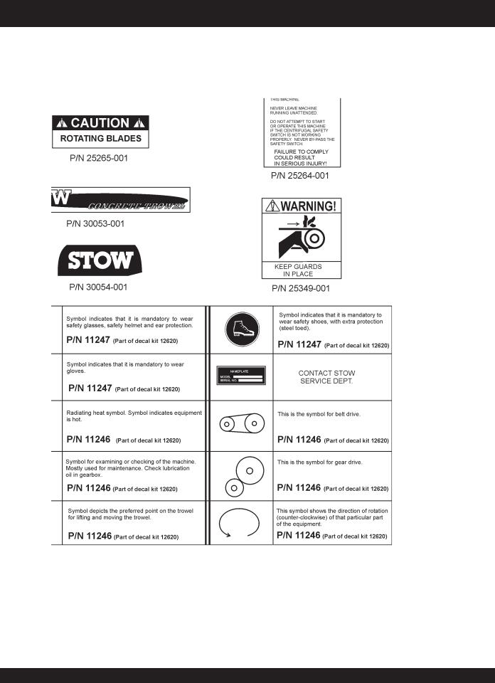
Machine Safety Decals
The SCT SERIESwalk-behind trowel is equipped with a number of safety decals.These decals are provided for operator safety and maintenance information. Figure 1 below illustrates these decals as they appear on the machine. Should any of these decals become unreadable, replacements can be obtained from your dealer.
Figure 1. SCT SERIESTrowel Decals
PAGE 12 — SCT SERIES WALK-BEHIND TROWEL— PARTS & OPERATION MANUAL — REV. #4 (04/02/07)

SCT SERIESTROWEL — SPECIFICATIONS (TROWEL)
SideView
Top View
Figure 2. SCT SERIESTrowel Dimensions
Table 1. STOW Trowel Specifications
MODEL |
SCT36 |
SCT46 |
A– Height (Lifting Hook) |
36.7 in. (931.6 mm) |
34.5 in. (876.2 mm) |
B– Height Engagement Lever) |
41.4 in. (1,044.2 mm) |
41.1 in. (1,044.2 mm) |
C–Width |
36.5 in. (927.1 mm) |
46.0 in. (1,168.4 mm) |
D–Length |
70.5 in. (1,789.4 mm) |
75.2 in. (1,910.1 mm) |
Weight – Operating |
SEE TABLE 3 |
|
Sound Pressure1 |
94 db |
97 db |
Vibration2 |
2.0g (19.6 m/s2) |
2.5g (24.5 m/s2) |
Ring Diameter |
36.5 in. (92.7 cm) |
46 in. (117 cm) |
Number of Blades |
4 |
4 |
Blade Tip Speed – FPM (m/s) |
1,290 fpm (6.5 m/s) |
1,290 fpm (6.5 m/s) |
Rotor – RPM (Gasoline) |
144 @ 3800 rpm |
144 @ 3800 rpm |
Path Width – in. (cm) |
36 in. (91.44 cm) |
46 in. (116.84) |
NOTE:
1.Sound pressure is a weighted measure. Measured at the operators ear position while the walk-behind trowel is operating at full throttle on concrete in a manner most often experienced in “normal” circumstances. Sound pressure may vary depending upon the condition of the concrete. Hearing protection is always recommended.
2.The vibration level indicated is the maximum RMS (Root Mean Square) value obtained at the handle grip while operating the walk-behind trowel on curing concrete in a manner most often experienced in “normal” circumstances. Values were obtained from all three axes of motion. The values shown represent the maximum RMS value from these measurements.
SCT SERIES WALK-BEHIND TROWEL — PARTS & OPERATION MANUAL — REV. #4 (04/02/07) — PAGE 13

SCT SERIESTROWEL— SPECIFICATIONS (ENGINES)
Table 2. Specifications (Engines)
Model |
HONDA GX160QX2 |
HONDA GX240K1QA2 |
HONDA GX340K1QAP2 |
|
|
|
|
|
|
|
Air-cooled 4 stroke, Single |
Air-cooled 4 stroke, Single |
Air-cooled 4 stroke, Single |
|
Type |
Cylinder, OHV, Horizontal Shaft |
Cylinder, OHV, Horizontal Shaft |
Cylinder, OHV, Horizontal Shaft |
|
|
Gasoline Engine |
Gasoline Engine |
Gasoline Engine |
|
|
|
|
|
|
Bore X Stroke |
2.7 in. x 1.8 in. |
2.9 in. x 2.3 in. |
3.2 in. x 2.5 in. |
|
(68 mm x 45 mm) |
(73 mm x 58 mm) |
(82 mm x 64 mm) |
||
|
||||
|
|
|
|
|
Displacement |
9.9 cu-in. (163 cc) |
14.81 cu-in. (242cc) |
20.6 cu-in. (337cc) |
|
|
|
|
|
|
Max Output |
5.5 H.P./4000 R.P.M. |
8.0 H.P./3600 R.P.M. |
11.0 H.P./3600 R.P.M. |
|
|
|
|
|
|
Fuel Tank Capacity |
0.95 U.S. gal. (3.6 liters) |
1.59 U.S. gal. (6 liters) |
1.72 U.S. gal (6.5 liters) |
|
|
|
|
|
|
Fuel |
Unleaded Automobile Gasoline |
Unleaded Automobile Gasoline |
Unleaded Automobile Gasoline |
|
|
|
|
|
|
Lube Oil Capacity |
0.63 U.S. qt. (0.60 liter) |
1.16 U.S. qt. (1.1 liters) |
1.16 U.S. qt. (1.1 liters) |
|
|
|
|
|
|
Speed Control |
Centrifugal Fly-weight Type |
Centrifugal Fly-weight Type |
Centrifugal Fly-weight Type |
|
Method |
||||
|
|
|
||
|
|
|
|
|
Starting Method |
Recoil Start |
Recoil Start |
Recoil Start |
|
|
|
|
|
|
Dimension |
12.0 x 14.3 x 13.2 in. |
14.0 x 16.9 x 16.1 in. |
15.0 x 17.7 x 17.4 |
|
(L x W x H) |
(304 x 362 x 335 mm) |
(355 x 430 x 410 mm) |
(380 x 450 x 443 mm) |
|
|
|
|
|
|
Dry Net Weight |
33.1 lbs. (15.0 Kg) |
55.1 lbs. (25 Kg) |
68.4 lbs. (31 Kg) |
|
|
|
|
|
Table 3. Specifications (Trowel Weights)
MODEL |
POWER SOURCE |
OPERATING WEIGHT |
SHIPPING WEIGHT |
|
(with handle) |
||||
|
|
|
||
|
|
|
|
|
SCT36H55 |
5.5 HP Honda |
190 lbs. (87 Kg) |
230 lbs. (105 Kg) |
|
|
|
|
|
|
SCT36H80 |
8 HP Honda |
214 lbs. (97 Kg) |
254 lbs. (116 Kg) |
|
|
|
|
|
|
SCT46H80 |
8 HP Honda |
242 lbs. (110 Kg) |
292 lbs. (133 Kg) |
|
|
|
|
|
|
SCT46H11 |
11 HP Honda |
295 lbs. (134 Kg) |
355 lbs. (161 Kg) |
|
|
|
|
|
PAGE 14 — SCT SERIES WALK-BEHIND TROWEL— PARTS & OPERATION MANUAL — REV. #4 (04/02/07)

SCT SERIESTROWEL— GENERAL INFORMATION
SCT SERIESWalk-BehindTrowel Familiarization
This walk-behind trowel is designed for the floating and finishing of concrete slabs.
Take a walk around the trowel. Take notice of all the major components (see Figure 3, pages 16 and 17) like the engine, blades, quick adjust control, (on those equiped models), air cleaner, centrifugal stop switch etc. Check that there is always oil in the engine.
Read all the safety instructions carefully.Safety instructions will be found throughout this manual and on the trowel. Keep all safety information in good, readable condition. Operators should be well trained on the operation and maintenance of the trowel.
Before using your trowel, test it on a flat watered down section of finished concrete that is free of any debris and other objects.
This trial test run will increase your confidence in using the trowel and at the same time it will familiarize you with the trowel’s controls. In addition you will understand how the trowel handles under actual conditions.
Engines
The 36" trowel is available with a 5.5 HP HONDA or an 8.0 HP HONDA gasoline engine while the 46" trowel is available with an 8.0 HP HONDA or an 11.0 HP HONDA gasoline engine. Refer to the engine owner’s manual for instructions regarding the operation and maintenance of your engine. The engine manual is included with your trowel at the time of shipment. Please contact your nearest Multiquip Dealer for a replacement should the original manual disappear or become unusable.
Drive System
Power is transferred from the engine to the gearbox input shaft via a V-belt or pulley drive system.The pulley engages using a centrifugal clutch.
Gearbox
The gearbox is located beneath the engine and transfers power to the rotor or spider assembly. The gearbox controls the rotational speed of the trowel and is equipped with two shafts (input and output).
Spider
The vertical output shaft of the gearbox connects to a cast hub called the spider. The spider has 4 arms that extend outward that are used for attachment of blades or other accessories. Remember as the gearbox output shaft rotates so does the spider assembly.
Blades
The blades of the trowel finish the concrete as they are rotated around the surface. Blades are classified as combination (8 inches wide), float (10 or 8 inches wide), and finish (6 inches wide). This trowel comes equipped with four blades per rotor equally spaced in a radial pattern and attached to vertical rotating shaft by means of a spider assembly.
Centrifugal Stop Switch
In the event of a trowel runaway condition, (operator releases the handle), a centrifugal stop switch will stop the engine and bring the trowel to a halt.
CAUTION
NEVER attempt to lift the trowel by yourself. ALWAYS get the assistance of another person to help lift the trowel or use a crane or lifting device to move the trowel.
Moving the SCT SERIESWalk-BehindTrowel
This walk-behind trowel is designed to be moved and handled in several ways. One way to lift the trowel is to use an optional lifting tube. See page 24, Figure 20. When using the lifting tube, always use two persons to lift the trowel.
These models have a lifting bail installed so strap or chain can be attached, allowing a forklift or crane to lift the trowel up onto a slab of concrete. Use a lifting device of adequate lifting capacity to lift the trowel.
Training
For proper training, please use the “TRAINING CHECKLIST” located in the front of this manual (Page 6). This checklist will provide an outline for an experienced operator to provide training to a new operator.
SCT SERIES WALK-BEHIND TROWEL — PARTS & OPERATION MANUAL — REV. #4 (04/02/07) — PAGE 15
SCT SERIESTROWEL— CONTROLS AND COMPONENTS
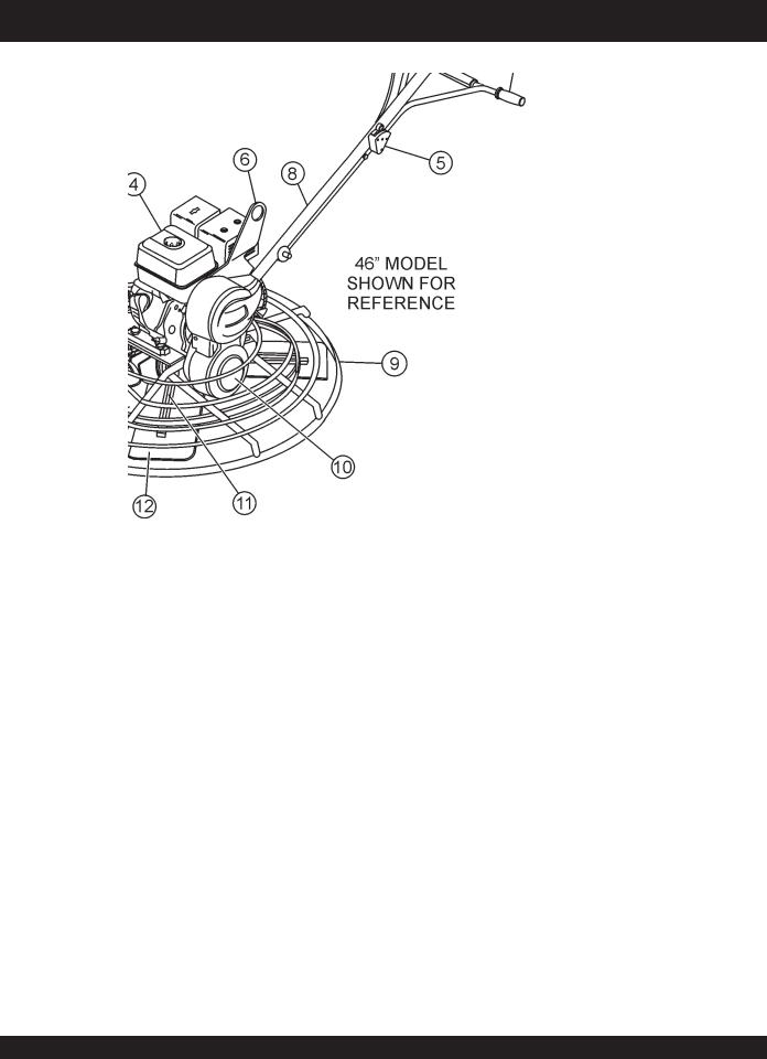
Figure 3. SCT SERIESWalk-Behind Trowels
Figures 3 shows the location of the basic controls or components, for the SCT SERIEStrowel. Listed below is a brief explanation of each control or component
1.Pitch Control -Turn this "StarWheel" clockwise for increase blade pitch, and counter-clockwise for decrease blade pitch
2.Hand Grip/Handle Bar – When operating the trowel, place both hands on each grip to maneuver the trowel. Replace hand grips when they become worn or damaged.
3.Throttle – Controls engine speed.
4.Engine – This trowel uses a Honda gasoline engine.
5.Centrifugal Safety Stop Switch – In the event the operator loses control of the trowel, this switch will shut-down the engine.
6.Trowel Lifting Point – Use a hoist, forklift, or other suitable lifting device to lift the trowel on and off the concrete slab.
7.Engine ON-OFF Switch– Turn to the "ON" position for starting the engine and to the "OFF" position to prevent the engine from starting.
8.MainTube - Houses throttle control and pitch cables.
9.Guard RingNEVER! put hands or feet inside guard ring.
10.V-Belt Cover – Remove this cover to gain access to the V- belt. NEVER operate the trowel with this cover removed.
11.TrowelArm–NEVER operate the trowel with a bent, broken or out of adjustment trowel arm. If the blades show uneven wear patterns or some blades wear out faster than others, the trowel arm may need to be adjusted. Use the trowel arm adjustment tool P/N 1817 to adjust the trowel arms.
12.Blades –This trowel is equipped with combination blades. These blades are versatile and should take care of most troweling needs. In addition float discs can be attached to the trowel arms that will allow the trowel to float on "wet" concrete.
13.Stabilizer Ring – Reduces trowel arm vibration. Helps stabilize trowel arm.
PAGE 16 — SCT SERIES WALK-BEHIND TROWEL— PARTS & OPERATION MANUAL — REV. #4 (04/02/07)

SCT SERIESTROWEL— BASIC ENGINE
|
Figure 4. Engine Controls and Components |
|
||||
INITIAL SERVICING (ENGINE) |
5. |
FuelValve Lever – OPEN to let fuel flow, CLOSE to stop |
||||
The engine (Figure 4) must be checked for proper lubrication and |
|
the flow of fuel. |
|
|||
6. |
Choke Lever – Used in the starting of a cold engine, or in |
|||||
filled with fuel prior to operation. Refer to the manufacturers engine |
||||||
manual for instructions & details of operation and servicing. |
|
cold weather conditions. The choke enriches the fuel |
||||
1. Fuel Filler Cap – Remove this cap to add unleaded |
|
mixture. |
|
|||
7. |
Air Cleaner – Prevents dirt and other debris from entering |
|||||
gasoline to the fuel tank. Make sure cap is tightened |
||||||
securely. DO NOT over fill. |
|
the air intake system. Remove wing-nut on top of air filter |
||||
|
|
|
|
cannister to gain access to filter element. |
||
|
|
|
|
|
Operating the engine without an air |
|
|
|
|
|
|
filter, with a damaged air filter, or a |
|
|
DANGER |
|
|
NOTE |
||
|
|
|
filter in need of replacement will |
|||
|
|
|
|
|
||
|
|
|
|
|
allow dirt to enter the engine, causing |
|
Addingfueltothetankshouldbedoneonlywhen |
|
|
rapid engine wear |
|||
theengineisstoppedandhashadanopportunity |
8. |
Spark Plug – Provides spark to the ignition system. Set |
||||
to cool down. In the event of a fuel spill,DONOT |
||||||
|
|
|
||||
attempttostarttheengineuntilthefuelresiduehasbeencompletely |
spark plug gap to 0.6 - 0.7 mm (0.028 - 0.031 inch) Clean |
|
spark plug once a week. |
||
wiped up, and the area surrounding the engine is dry. |
||
|
2. Throttle Lever – Used to adjust engine RPM speed (lever advanced forward SLOW, lever back toward operator
FAST).
3. Engine ON/OFF Switch – ON position permits engine starting, OFF position stops engine operations.
4. Recoil Starter (pull rope) – Manual-starting method. Pull the starter grip until resistance is felt, then pull briskly and smoothly.
9. Muffler – Used to reduce noise and emissions.
WARNING
Enginecomponentscangenerateextremeheat. To prevent burns, DO NOT touch these areas while the engine is running or immediately after operating. NEVER operate the engine with the muffler removed.
10. Fuel Tank – Holds unleaded gasoline. For additional information refer to engine owner's manual.
SCT SERIES WALK-BEHIND TROWEL — PARTS & OPERATION MANUAL — REV. #4 (04/02/07) — PAGE 17

SCT SERIESTROWEL — ASSEMBLY AND INSTALLATION
Assembly and Installation
Before the trowel can be put into operation there are some components that must be installed before the trowel can be used. This section provided general instructions on how to install those components.
HandleTube Installation
1.Install the handletubeto the gearbox as shown in (Figure 5). The mounting hardware should be contained in the shipping container.
2.Connectthethrottlecabletotheengine.(Figure7). (Theair cleanerhousingmayhavetoberemovedtoprovideaccess for throttle cable installation.) When connecting the cable housing, make sure that no more than 1/4" (6.4mm) of the cable housing protrudes past the housing clamp on the engine.
Figure 7. Throttle Cable Connection
Figure 5. Handle Tube Installation
Throttle Cable Installation
1.Set the throttle (Figure 6) to the idle position (lever away from the operator).
3.Tighten cable clamp screw.
4.After the cable has been installed on the engine, work the throttle lever to verify the throttle cable is at the proper length. Adjust the cable as necessary.
5.Reinstall the air cleaner housing if previously removed.
Figure 6. Throttle
PAGE 18 — SCT SERIES WALK-BEHIND TROWEL— PARTS & OPERATION MANUAL — REV. #4 (04/02/07)
SCT SERIESTROWEL — ASSEMBLY AND INSTALLATION
Safety StopWire
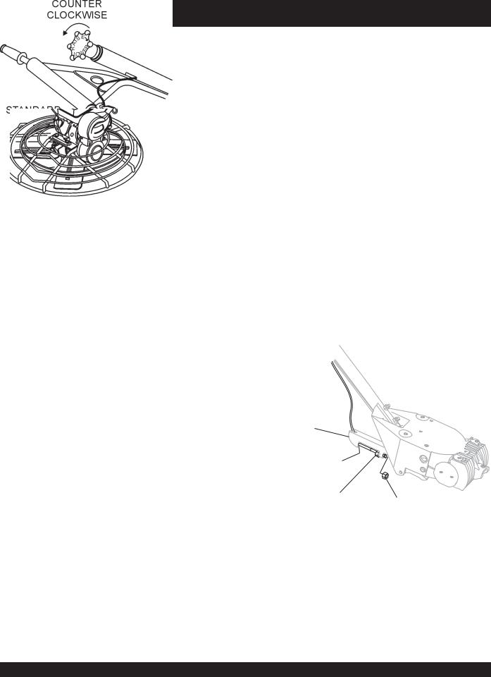
Locate the SAFETY STOP wire protruding from the handle tube (Figure 8) and connect it to the tail wire on the engine.Test the safety stop switch to insure proper operation.
Figure 8. Engine Safety Stop Wire Connection
Pitch Cable Installation
Figure 9. "No Pitch" Position
Figure 10. Blade Pitch Cable
2.Remove one brass set nut from the blade pitch cable end as shown in (Figure 10).
3.Thread the second brass set nut towards the cable as far as possible.
4.Insert the cable end through the yoke eyelet (Figure 11) Tighten the first brass set nut by hand to remove all the slack from the cable.
YOKE |
|
THREAD CABLE END |
|
THROUGH YOKE EYELET |
|
TIGHTEN SECOND |
|
BRASS SET NUT |
USE A WRENCH TO |
AGAINST YOKE BOSS |
TIGHTEN FIRST BRASS |
|
SET NUT AGAINST YOKE BOSS |
Figure 11. CableYoke Attachment
1.Expose the pitch cable to maximum by adjusting the handle pitch to the "no pitch" position. On the standard model turn the pitch control counter-clockwise, (Figure 9).
5.Using a wrench, tighten the second brass set nut up against the yoke boss.This will lock the cable in place.
6.Use a wrench and finish tightening the first brass set nut up against the yoke boss.
SCT SERIES WALK-BEHIND TROWEL — PARTS & OPERATION MANUAL — REV. #4 (04/02/07) — PAGE 19

CAUTION
NEVER operate the trowel in a confined area or enclosed area structure that does not provide ample free flow of air.
ALWAYS wear approved eye and hearing protection before operating the trowel.
NEVER place hands or feet inside the guard rings while the engine is running. ALWAYS shut the engine down before performing any kind of maintenance service on the trowel.
SCT SERIESTROWEL— PRE-INSPECTION
Figure 12. Engine Oil Dipstick (Removal)
3.Insertandremovethedipstickwithoutscrewingitintothefiller neck. Check the oil level shown on the dipstick.
4.If the oil level is low (Figure 13), fill to the edge of the oil filler hole with therecommended oiltype(Table 4). Maximum oil capacity is 400 cc.
It is recommended that the trowel's safety stop switch is used |
|
|
to stop the engine after every use. Doing this will verify that the |
|
|
switch is working properly and presents no danger to the operator. |
Reference manufacturer engine |
|
|
NOTE |
manual for specific servicing |
Before Starting |
instructions. |
|
|
||
1. |
Read safety instructions at the beginning of manual. |
|
2. |
Cleanthetrowel,removingdirtanddust,particularlythe air |
|
|
filterandcarburetor. |
|
3. |
Check theairfilterfor dirtanddust. Ifairfilterisdirty,replace |
|
|
air filter with a new one as required. |
|
4. |
Check carburetor for external dirt and dust. Clean with dry |
|
|
compressedair. |
|
5. Check fastening nuts and bolts for tightness.
Engine Oil Check
1.Tochecktheengineoillevel,placethe trowelonsecurelevel ground with the engine stopped.
2.Remove the filler dipstick from the engine oil filler hole (Figure 12) and wipe it clean.
Figure 13. Engine Oil Dipstick (Oil Level)
Table 4. Oil Type
Season |
Temperature |
Oil Type |
|
|
|
Summer |
25°C or Higher |
SAE 10W-30 |
|
|
|
Spring/Fall |
25°C~10°C |
SAE 10W-30/20 |
|
|
|
Winter |
0°C or Lower |
SAE 10W-10 |
|
|
|
PAGE 20 — SCT SERIES WALK-BEHIND TROWEL— PARTS & OPERATION MANUAL — REV. #4 (04/02/07)
SCT SERIESTROWEL— PRE-INSPECTION
Explosive Fuel
CAUTION
Motor fuels are highly flammable and can be dangerous if mishandled. DO NOT smoke while refueling. DO NOT attempt to refuel the trowel if the engine is hot! or running.
Fuel Check
1.Remove the gasoline cap located on top of fuel tank.
2.Visuallyinspecttoseeiffuellevelislow. Iffuelislow,replenish with unleaded fuel.
3.When refueling, be sure to use a strainer for filtration. DO NOT top-off fuel. Wipe up any spilled fuel.
NEVER! disable or disconnect the NOTE safety stopswitch. It is provided for operator safety.Injury may result if it is disable, disconnected or
improperly maintained.
Gearbox Oil
1.Determine if the gearbox oil is low by viewing the oil sight glass/fill plug located on the side of the gearbox.This plug will be marked by the "check" decal. See (Figure 14).The correct level of the lubrication oil should be to the bottom of the sight glass/fill plug.
GEARBOX
OIL SIGHT/
FILL PLUG
DRAIN
PLUG
Figure 14. Gearbox
V-belt Check
A worn or damaged V-belt can adversely affect the performance of the trowel.If a V-belt is defective or worn simply replace theVbelt as outlined in the maintenance section of this manual.
Blade Check
Check for worn or damaged blades. Check to see if one blade is worn out while the others look new.If this is the case there could be a blade pitch problem. Refer to the maintenance section of this manual for blade pitch adjustment procedure. Always replace any worn or damaged blades.
CONTROLS
Safety Stop Switch
This trowel has been equipped with a safety safety stop switch. Safety stop switches should be tested every time the engine is started.
NEVER! disable or disconnect the safety stopswitch. It is provided for NOTE operator safety.Injury may result if it is disable, disconnected or
improperly maintained.
CentrifugalType Safety Stop Switch
(Figure 15) The switching mechanism of this switch should operate freely and should alwaysbe kept in this condition. With the switch in the "OFF" position, the engine should not start or run.The purpose of this switch is to stop the engine in a runaway situation,(i.e.theoperatorreleasingthehandleduringoperation).
Figure 15. Centrifugal Safety Stop Switch
2.If lubrication oil cannot be seen in the sight glass, fill with type ISO 680 (P/N 10139) gearbox lubricant oil until the oil will show at the center of the oil sight glass when the gearbox is level..
SCT SERIES WALK-BEHIND TROWEL — PARTS & OPERATION MANUAL — REV. #4 (04/02/07) — PAGE 21

SCT SERIE STROWEL — INITIAL START-UP
This section is intended to assist the operator with the initial start-up of the walk-behind trowel. It is extremely important that this section be read carefully before attempting to use the trowel in the field.
DO NOT use your trowel until this section is thoroughly understood.
CAUTION |
DO NOT attempt to operate the trowel until |
|
|
the Safety, General Information and |
|
|
Inspection sections of this manual have |
|
|
been read and |
thoroughly understood. |
|
Depending on |
engine manufacturer, |
|
operating steps may vary. See engine |
|
|
manufactures operating manual. The |
|
|
following start-up procedure makes |
|
reference to a HONDA Gasoline Engine
(Manual Start).
LIFTING THE TROWEL
CAUTION
When lifting of the trowel is required always use two people to lift the trowel onto a slab. If another person is not available attach a crane or lifting device to the trowel's lifting bale.
With one person lifting from the main handle (Figure 16), and another person lifting from the front of the frame, lift the trowel onto a slab.
CAUTION
The trowel must be stabilized by the person carrying the operator’s handle (Figure 16). If it is not stabilized properly the handle may swingaroundandflipthetrowel,thuscausing damage to the trowel and bodily injury.
Lifting Bail
A lifting bail is provided at an optimal lifting point for moving the trowel. A hoist or forklift can be used to lift the trowel up onto a concrete slab. A cranecan be used to lift the trowel onto a building.
Extra care MUST be taken when lifting the machine off the ground. Serious damage to the machine or personal injury could be caused by dropping a trowel.
Starting the Engine
1.Place the engine fuel valve lever (Figure 17) to the "ON" position.
Figure 17. Engine Fuel Valve Lever
2. Make sure the throttle (Figure 18) is in the "idle" position.
Figure 16. Lifting the Trowel
Figure 17. Throttle (Idle Position)
PAGE 22 — SCT SERIES WALK-BEHIND TROWEL— PARTS & OPERATION MANUAL — REV. #4 (04/02/07)

SCT SERIESTROWEL — INITIAL START-UP
3.Placethecentrifugal safetystopswitch (Figure19)inthe "ON"position.
CAUTION
NEVER disable or disconnect the centrifugal safety stop switch. It is provided for the operators’ safety and injury may result if it is disabled, disconnected or improperly maintained.
Figure 19. Centrifugal Safety Stop Switch
4.Place the Choke Lever (Figure 20) in the "CLOSED " position.
Figure 21. Starter Grip
6.If the engine has started, slowly return the choke lever (Figure 20) to the "OPEN" position. If the engine has not started repeat steps 1 through 5.
7.Before the trowel is placed into operation, run the engine for several minutes. Check for fuel leaks, and noises that would associate with a loose guard ring and/or covers.
8.To begin troweling, move the throttle lever (Figure 22) toward the "RUN" position by pulling back toward the operator..
Figure 22. Throttle (Run Position)
Figure 20. Engine Choke Lever
5.Grasp the starter grip (Figure 21) and slowly pull it out.The resistancebecomesthehardestatapositioncorresponding to the compression point. Pull the starter grip briskly and smoothlyforstarting.
SCT SERIES WALK-BEHIND TROWEL — PARTS & OPERATION MANUAL — REV. #4 (04/02/07) — PAGE 23

SCT SERIESTROWEL — OPERATION
The following steps are intended as a basic guide to machine operation, and are not to be considered a complete guide to concrete finishing. We suggest that all operators, (experienced and novice), read “Slabs on Grade” published by the American Concrete Institute, Detroit, Michigan. Read the “Training” section of this manual for more information.
PITCHINGTHE BLADES
1.To pitch the blades upwards using the "Standard" handle, (Figure23)simplyturnthestar-wheelclockwise.Turningthe starwheelcounterclockwise willcausethebladestolayflat.
Figure 23. Pitching the Blades
Figure 24 below illustrates a typical walk-behind trowel application. Practice maneuvering the trowel.The trick is to let the trowel do the work.
Maneuvering the Trowel
1.With a secure foothold and a firm grasp on the handles slowly increase the engine speed until the desired blade speed is obtained.
2.To maneuver the trowel, gently lift up on or press down on the main trowel handle. To move the machine to the operator’s left, lift up on the handle, to move machine to the right, push down on the handle.
3.The best method for finishing concrete is to slowly walk backwards (Figure 24) with the trowel, guiding the trowel from side to side.This will cover all footprints on wet concrete.
4.Remember that if you let go of the trowel, just step away and let the trowel come to a complete stop before trying to recover the trowel.
5.Continuetopracticemaneuveringthetrowel.Trytopractice as if you were finishing a slab of concrete. Practice edging and covering a large area.
WARNING
NEVER place your feet or hands inside the guard rings while starting or operating this equipment. ALWAYS keep clear of rotating or moving parts while operating this equipment.
PAGE 24 — SCT SERIES WALK-BEHIND TROWEL— PARTS & OPERATION MANUAL — REV. #4 (04/02/07)

Blades
Blades should be changed when NOTE they fail to finish concrete in a
satisfactory manner.
Blades are a vital part of finishing concrete. This trowel, or finisher, has been designed to finish concrete and the blades are built to stringent quality standards out of the finest trowel steel. If you need replacement blades, consult your parts list in this manual for part numbers and order them from your Multiquip parts dealer or importer.
Combo Blades
This trowel was equipped with combination float/finish (Figure 25) blades as original equipment. These blades have been designed for optimum performance in both the floating and finishing operations. These blades are versatile and should take care of most troweling needs.
Figure 25. Combination Blade
Finish Blades (Optional)
These blades (Figure 26) have been specifically designed for finish operations with this trowel. They will provide a premium surface finishing capability from your trowel. They should only be used after the concrete has set to the point where the trowel does not sink into the concrete when placed on it.
Figure 26. Finish Blade
SCT SERIESTROWEL — OPTIONS
Clip-On Float Blades (Optional)
These blades will clip on to an existing installed blade, (Figure 27), allowing the finisher to "float" on “wet” concrete so that the troweling operation can begin as early as possible. They can be easily removed, so when the concrete is sufficiently cured, the troweling operation can continue.
Figure 27. Clip-On Float Blade
Float Discs (Optional)
These round discs (Figure 28) attach to the spiders and allow the machine to “float” on “wet” concrete. The disc design allows early floating and easy movement from wet to dry areas.They are also very effective in embedding large aggregates and surface hardeners.
Figure 28. Float Disk
Trowel Arm Adjustment Tool
If blades show uneven wear patterns or some tend to wear out faster than others, the trowel arms may need to be adjusted. A special tool P/N 1817, (Figure 29) is available that can be used to adjust all of the trowel arms consistently.
See page 33 for Trowel Arm Adjustment procedures using this tool.
Figure 29.Trowel Arm Adjustment Fixture
SCT SERIES WALK-BEHIND TROWEL — PARTS & OPERATION MANUAL — REV. #4 (04/02/07) — PAGE 25

SCT SERIESTROWEL — MAINTENANCE (ENGINE)
Engine Maintenance
Perform engine maintenance procedures as referenced by
Table 5 below:
Table 5. Engine Maintenance Schedule
|
|
|
FIRST |
|
EVERY |
EVERY |
EVERY |
EVERY |
DESCRIPTION (3) |
OPERATION |
BEFORE |
MONTH |
|
3 MONTHS |
6 MONTHS |
YEAR |
2 YEARS |
OR |
|
OR |
OR |
OR |
OR |
|||
|
|
|
|
|||||
|
|
|
10 HRS. |
|
25 HRS. |
50 HRS. |
100 HRS. |
200 HRS. |
|
|
|
|
|
|
|
|
|
Engine Oil |
CHECK |
X |
|
|
|
|
|
|
|
|
|
|
|
|
|
|
|
CHANGE |
|
X |
|
|
|
|
|
|
|
|
|
|
|
|
|
||
|
|
|
|
|
|
|
|
|
Air Cleaner |
CHECK |
X |
|
|
|
|
|
|
|
|
|
|
|
|
|
|
|
CHANGE |
|
|
|
X (1) |
|
|
|
|
|
|
|
|
|
|
|
||
|
|
|
|
|
|
|
|
|
All Nuts & Bolts |
Re-tighten If |
X |
|
|
|
|
|
|
Necessary |
|
|
|
|
|
|
||
|
|
|
|
|
|
|
|
|
|
|
|
|
|
|
|
|
|
Spark Plug |
CHECK-CLEAN |
|
|
|
|
X |
|
|
|
|
|
|
|
|
|
|
|
REPLACE |
|
|
|
|
|
|
X |
|
|
|
|
|
|
|
|
||
|
|
|
|
|
|
|
|
|
Cooling Fins |
CHECK |
|
|
|
|
X |
|
|
|
|
|
|
|
|
|
|
|
Spark Arrester |
CLEAN |
|
|
|
|
|
X |
|
|
|
|
|
|
|
|
|
|
Fuel Tank |
CLEAN |
|
|
|
|
|
X |
|
|
|
|
|
|
|
|
|
|
Fuel Filter |
CHECK |
|
|
|
|
|
X |
|
|
|
|
|
|
|
|
|
|
Idle Speed |
CHECK-ADJUST |
|
|
|
|
|
X (2) |
|
|
|
|
|
|
|
|
|
|
Valve Clearance |
CHECK-ADJUST |
|
|
|
|
|
|
X (2) |
|
|
|
|
|
|
|
|
|
Fuel lines |
CHECK |
|
|
Every 2 years (replace if necessary) (2) |
|
|||
|
|
|
|
|
|
|
|
|
(1)Service more frequently when used in DUSTY areas.
(2)These items should be serviced by your servic dealer, unless you have the proper tools and are mechanically proficient. Refer to the HONDA shop Manual for service procedures
(3)For commercial use, log hours of operation to determine proper maintenance intervals.
Reference manufacturer engine manual for specific servicing instructions.
PAGE 26 — SCT SERIES WALK-BEHIND TROWEL— PARTS & OPERATION MANUAL — REV. #4 (04/02/07)

SCT SERIESTROWEL — MAINTENANCE (ENGINE)
Maintenance
Performtheenginemaintenanceproceduresasindicatedbelow:
DAILY
■Thoroughly remove dirt and oil from the engine and control area.Clean or replace the air cleaner elements as necessary. Check and retighten all fasteners as necessary. Check the spring box and bellows for oil leaks. Repair or replace as needed.
WEEKLY
■Remove the fuel filter cap and clean the inside of the fuel tank.
■Remove or clean the filter at the bottom of the tank.
■Remove and clean the spark plug (Figure 30), then adjust the spark gap to 0.028 ~0.031 inch (0.6~0.7 mm).This unit has electronic ignition, which requires no adjustments.
Figure 30. Spark Plug Gap
ENGINEOIL
1.Drain the engine oil when the oil is warm as shown in Figure 31.
2.Remove the oil drain bolt and sealing washer and allow the oil to drain into a suitable container.
3.Replace engine oil with recommended type oil as listed in Table 4. DO NOT overfill. See Table 2 for oil capacity.
4.Install drain bolt with sealing washer and tighten securely.
DANGER :
DO NOT use gasoline as a cleaning solvent, because that would create a risk of fire or explosion.
ENGINEAIRCLEANER
1.Remove the air cleaner cover and foam filter element as shown in Figure 32.
2.Tap the paper filter element (Figure 32) several times on a hard surface to remove dirt, or blow compressed air [not exceeding 30 psi (207 kPa, 2.1 kgf/cm2)] through the filter elementfromtheaircleanercaseside.NEVER brushoffdirt. Brushingwillforcedirtintothefibers.Replacethepaperfilter element if it is excessively dirty.
3.Cleanfoamelementinwarm,soapywaterornonflammable solvent. Rinse and dry thoroughly. Dip the element in clean engineoilandcompletelysqueezeouttheexcessoilfromthe element before installing.
Figure 32. Engine Air Cleaner
Figure 31. Engine Oil (Draining)
SCT SERIES WALK-BEHIND TROWEL — PARTS & OPERATION MANUAL — REV. #4 (04/02/07) — PAGE 27

SCT SERIESTROWEL — MAINTENANCE
Seetheenginemanualsuppliedwith NOTE your machine for appropriate engine maintenance schedule and troubleshooting guide for problems.
At the front of the book (Page 7) there is a “Daily Pre-Operation Checklist ”. Make copies of this checklist and use it on a daily basis.
CAUTION!
ALWAYS allow the engine to cool before servicing. NEVER attempt any maintenance work on a hot! engine.
MAINTENANCE SCHEDULE
Daily (8-10 Hours)
1.Check the oil level in the engine crankcase and gear box, fill as necessary.
2.CheckV-belt.
Weekly (50-60 Hours)
1.Relube arms, thrust collar and clutch.
2.Replace blades if necessary.
3.Check and clean or replace the engine air filter as necessary.
4.Replace engine oil and filter as necessary, see engine manual.
Monthly (200-300 Hours)
1.Remove, clean, reinstall and relube the arms and thrust collar.
2.Adjust the blade arms.
Yearly (2000-2500 Hours)
1.Check and replace if necessary the arm bushings, thrust collar bushings and shaft seals.
2.Check pitch control cables for wear.
3.Adjust blade speed.
Trowel Arm Adjustment Procedure
The following procedure should be NOTE followed to adjust trowel arms when it becomes apparent that the trowel is finishing poorly or in need of
routine maintenance.
A level, clean area to test the trowel prior to and after is essential. Any unlevel spots in the floor or debris under the trowel blades will give an incorrect perception of adjustment. Ideally, a 5 x 5" three-quarter inch thick flat steel plate should be used for testing.
1.To determine which blades need adjustment, place the trowelinthetestarea(three-quarterinchthickplate)andlook for the following conditions:
■Pitch the blades as flat as possible and look at the adjustment bolts.They should all barely make contact with the lower wear plate on the spider. If you can see that one of them is not making contact, some adjustment will be necessary.
■Is the machine wearing out blades unevenly (i.e. one blade is completely worn out while the others look new)?
Figure 33 below illustrates a "worn spider bushings or bent trowel arms". Check to see that adjustment bolt is barely touching (0.10" max. clearance) lower wear plate. All alignment bolts should be spaced the same distance from the lower wear plate.
Figure 33. Worn Spider Plate
Figure 34 below illustrates the "correct alignment " for a spider plate (as shipped from the factory).
Figure 34. Correct Spider Plate Alignment
PAGE 28 — SCT SERIES WALK-BEHIND TROWEL— PARTS & OPERATION MANUAL — REV. #4 (04/02/07)
SCT SERIESTROWEL — MAINTENANCE
2.Start engine, and bring trowel blades up to full speed and look for the following conditions:
■Does the trowel have a perceived rolling or bouncing motion when in use?
■Look at the trowel while it is running, does the guard ring “rock up and down” relative to the ground?
Spider Removal
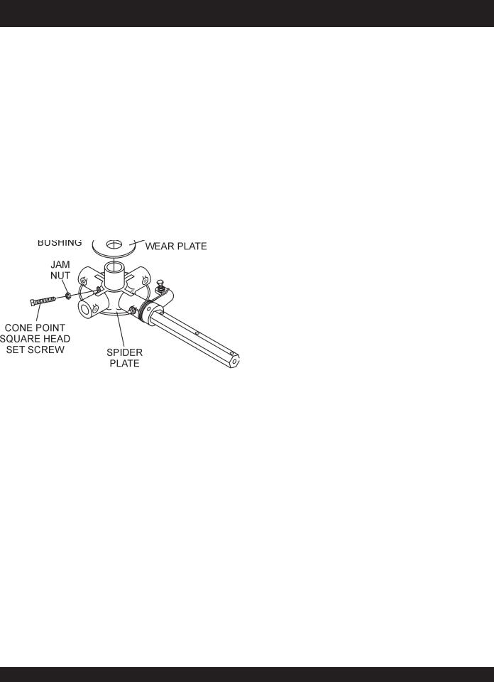
1.Onceitisdeterminedthatanadjustmentisrequired,remove the spider assembly from the gearbox shaft as follows:
a.Locate the cone point square head set screw (Figure 35) and attached jam nut found on the side of the spider assembly.
b.Loosen the jam nut and cone point square head set screw, and carefully lift the uppertrowelassemblyoff ofthespiderassembly. Aslighttapwitharubbermallet maybe necessary todislodge the spider fromthe main shaft of the gearbox.
c.If the trowel is equipped with an outer stabilizer ring (Figure 36), remove the four bolts at the end of each spiderarm.
Figure 36. Stabilizer Ring
d.Examine stabilizer ring for out of round or bends. If ring isdamaged,replacering.Ifringisfoundtobecorrectwith no damage, set aside.
Trowel Arm Removal
1.Each trowel arm is held in place at the spider plate by a hex headbolt (zerkgreasefitting)andarollpin.Removeboththe hex head bolt and the roll pin (Figure 37) from the spider plate.
2.Remove the trowel arm from the spider plate.
Figure 35. Spider/Gearbox Removal
Figure 37. Removing Roll Pin
and Zerk Grease Fitting
SCT SERIES WALK-BEHIND TROWEL — PARTS & OPERATION MANUAL — REV. #4 (04/02/07) — PAGE 29

SCT SERIESTROWEL — MAINTENANCE
3.Should the trowel arm inserts (bronze bushing ) come out withthetrowelarm,removethebushingfromthetrowelarm andset asideinasafeplace. If thebushingisretained inside the spider plate, carefully remove the bushing.
4.Examine the bronze trowel arm bushing insert (Figure 38), andcleanifnecessary. Replacethebushing ifout-of-round or worn.
Figure 38. Bronze Bushings
Trowel Blade Removal
1.Remove the trowel blades from the trowel arm by removing the hex head bolts (Figure 39) from the trowel arm. The 36" modelwillhavetwohexheadboltsperarmandthe 46"model will have three hex head bolts per arm. Set blades aside.
Trowel Arm FlatnessTest
1.Usingapieceof3/4inchthicksteelplateoranysurfacewhich is true and flat, check all six sides of each trowel arm for flatness.
2.Check each of the six sides of the trowel arm (hex section only) using a ten thousands of an inch (max.) feeler gauge (Figure 40) between the flat of the trowel arm and an ex- tremely flat test surface.
|
Figure 40. Trowel Arm FlatnessTest |
3. |
If the trowel arm is found to be uneven or bent, replace the |
|
trowel arm. A bent trowel will not allow the trowel to operate |
|
in a smooth fluid rotation. |
4. |
Next,checkeachofthesixsidesof theroundmachinedshaft |
|
sectionofthetrowelarm.Eachsectionshouldhavethesame |
Figure 39. Trowel Blades |
clearance betweentheroundofthetrowelarmshaftandthe |
testsurface. |
2.Wirebrushanybuild-upofconcretefromallsixsidesofthe trowel arm. Repeat this for the remaining three arms.
Trowel arms can be damaged by rough handling or by striking NOTE exposed plumbing or forms while in operation. ALWAYS look-out for objects which might cause damage
to the trowel arms.
PAGE 30 — SCT SERIES WALK-BEHIND TROWEL— PARTS & OPERATION MANUAL — REV. #4 (04/02/07)
 Loading...