

Page 1

OPERATION AND PARTS MANUAL
SERIES
MODEL HTN-31VTCSL5
MODEL HTO-31VTCSL5
RIDE-ON POWER TROWEL
(B &S VANGUARD GASOLINE ENGINE)
Revision #6 (07/09/07)
To find the latest revision of this
publication, visit our website at:
www.multiquip.com
THIS MANUAL MUST ACCOMPANY THE EQUIPMENT AT ALL TIMES.
P/N 12899
Page 2

HTN/HTO-31V — PROPOSITION 65 WARNING
Engine exhaust and some of
its constituents, and some dust created
by power sanding, sawing, grinding,
drillingandotherconstructionactivities
contains chemicals known to the State
of California to cause cancer, birth
defects and other reproductive harm.
Some examples of these chemicals are:
Leadfromlead-basedpaints.
Crystallinesilicafrombricks.
Cementandothermasonryproducts.
Arsenicandchromiumfrom chemically
treatedlumber.
Your risk from these exposures varies,
dependingonhowoftenyoudothistype
of work. To reduce your exposure to
these chemicals: work in aALWAYS
well ventilated area, and work with
approved safety equipment, such as
dust masks that are specially designed
to filter out microscopic particles.
PAGE 2 — HTN 31V
HTN/HTO-31V • RIDE-ON POWER TROWEL — OPERATION AND PARTS MANUAL — REV. #6 (07/09/07) — PAGE 2
Page 3
HTN/HTO-31V — SILICOSIS/RESPIRATORY HAZARDS
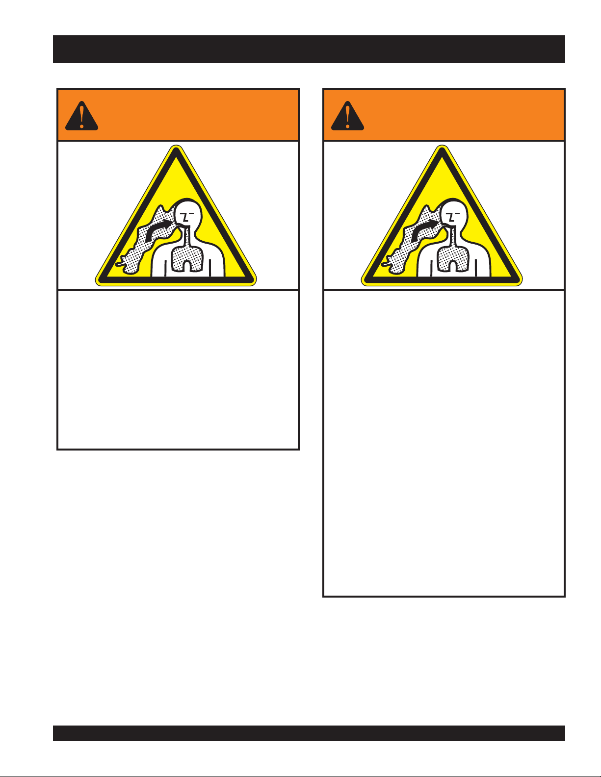
WARNING
SILICOSIS WARNING RESPIRATORY HAZARDS
Grinding/cutting/drilling of masonry, concrete, metal and
other materials with silica in their composition may give
off dust or mists containing crystalline silica. Silica is a
basic component of sand, quartz, brick clay, granite and
numerous other minerals and rocks. Repeated and/or
substantial inhalation of airborne crystalline silica can
cause serious or fatal respiratory diseases, including
silicosis. In addition, California and some other
authorities have listed respirable crystalline silica as a
substance known to cause cancer. When cutting such
materials, always follow the respiratory precautions
mentioned above.
WARNING
Grinding/cutting/drilling of masonry, concrete, metal and
other materials can generate dust, mists and fumes
containing chemicals known to cause serious or fatal
injury or illness, such as respiratory disease, cancer,
birth defects or other reproductive harm. If you are
unfamiliar with the risks associated with the particular
process and/or material being cut or the composition of
the tool being used, review the material safety data
sheet and/or consult your employer, the material
manufacturer/supplier, governmental agencies such as
OSHA and NIOSH and other sources on hazardous
materials. California and some other authorities, for
instance, have published lists of substances known to
cause cancer, reproductive toxicity, or other harmful
effects.
Control dust, mist and fumes at the source where
possible. In this regard use good work practices and
follow the recommendations of the manufacturers or
suppliers, OSHA/NIOSH, and occupational and trade
associations. Water should be used for dust
suppression when wet cutting is feasible. When the
hazards from inhalation of dust, mists and fumes cannot
be eliminated, the operator and any bystanders should
always wear a respirator approved by NIOSH/MSHA for
the materials being used.
HTN/HTO- 31V • RIDE-ON POWER TROWEL — OPERATION AND PARTS MANUAL — REV. #6 (07/09/07) — PAGE 3
Page 4

HTN/HTO-31V — TABLE OF CONTENTS
MQ WHITEMAN — HTN/HTO-31V
RIDE-ON POWER TROWEL
(VANGUARD ENGINE)
California Proposition 65 Warning ............................. 2
Silicosis/Respiratory Warnings .................................. 3
Table Of Contents ..................................................... 4
Parts Ordering Procedures ....................................... 5
Training Checklist ...................................................... 6
Daily Pre-Operation Checklist ................................... 8
Safety Message Alert Symbols ............................ 9-10
Rules For Safe Operation .................................. 11-14
Dimensions/Specifications (Trowel) ........................ 15
Specifications (Engine) ........................................... 16
General Information ................................................ 17
Controls and Indicators ...................................... 18-19
Engine Components ............................................... 20
Setup ....................................................................... 21
Inspection ................................................................ 22
Operation ........................................................... 23-24
Maintenance (Engine)........................................ 25-26
Maintenance (Trowel) ........................................ 27-35
Troubleshooting (Trowel) ................................... 36-37
Troubleshooting (Engine) ................................... 38-39
Explanation Of Codes In Remarks Column ............ 40
Suggested Spare Parts ........................................... 41
COMPONENT DRAWINGS
Nameplate and Decals Assembly ...................... 42-43
Pivot Assembly .................................................. 44-45
Steering Handles Assembly ............................... 46-47
Steering Assist Control Assembly ...................... 48-49
Twin Pitch Assy. (Left/Right) ............................... 50-51
Twin Pitch and Mitre Box Assy. (Left/Right)........ 52-53
Engine Mounting Bracket Assembly .................. 54-55
Muffler Assy. S/N CC020199 and Below ............ 56-57
Muffler Assy. S/N CC020200 and Above ........... 58-59
Fuel Tank Assembly .......................................... 60-61
Clutch Assembly ................................................ 62-63
Radiator Guard/Overflow Bracket Assy. ............ 64-65
V-Belt Guard Assembly ...................................... 66-67
Engine Service Parts .......................................... 68-69
Gearbox Assembly (Left-Side) ........................... 70-73
Gearbox Assembly (Right-Side) ........................ 74-77
Drive Assembly .................................................. 78-79
5-Blade Spider Assembly (Left-Side) ................ 80-81
5-Blade Spider Assembly (Right-Side) ............. 82-83
Seat and Frame Assembly ................................. 84-85
Frame and Components Assembly ................... 86-87
Foot Pedals Assembly........................................ 88-89
Throttle Assembly .............................................. 90-91
Battery Assembly ............................................... 92-93
Spray Assembly ................................................. 94-95
Control Panel Assembly ..................................... 96-97
E-Z Mover and Lift Handle Assembly ................ 98-99
Terms and Conditions Of Sale .............................. 100
Specifications and
NOTE
HTN/HTO-31V • RIDE-ON POWER TROWEL — OPERATION AND PARTS MANUAL — REV. #6 (07/09/07) — PAGE 4
part numbers are
subject to change
without notice.
PAGE 4 — HTN 31V
Page 5

PARTS ORDERING PROCEDURES
Ordering parts has never been easier!
Choose from three easy options:
Effective:
January 1
st
, 2006
Best Deal!
Order via Internet
(Dealers Only)
Order parts on-line using Multiquip’s SmartEquip website!
■
View Parts Diagrams
■
Order Parts
■
Print Specification Information
Goto www.multiquip.com and click on
Order Parts
Order via Fax
to log in and save!
(Dealers Only)
All customers are welcome to order parts via Fax.
Domestic (US) Customers dial:
1-800-6-PARTS-7 (800-672-7877)
Non-Dealer Customers:
Contact your local Multiquip Dealer for
parts or call 800-427-1244 for help in
locating a dealer near you.
:
:
Order via Phone:
If you have an MQ Account, to obtain a
Username and Password, E-mail us at:
parts@multiquip.com.
To obtain an MQ Account, contact your
District Sales Manager for more information.
internet
Use the
on
Standard orders
and qualify for a 5% Discount
for all orders which include
complete part numbers.*
Fax
your order in and qualify for a 2% Discount
on
Standard orders
for all orders which include
complete part numbers.*
Domestic (US) Dealers Call:
1-800-427-1244
International Customers
their local Multiquip Representatives for
Parts Ordering information.
Note: Discounts Are Subject To Change
Note: Discounts Are Subject To Change
should contact
When ordering parts, please supply:
❒❒
Dealer Account Number
❒
❒❒
❒❒
❒
Dealer Name and Address
❒❒
❒❒
❒
Shipping Address (if different than billing address)
❒❒
❒❒
Return Fax Number
❒
❒❒
❒❒
Applicable Model Number
❒
❒❒
❒❒
Quantity, Part Number and Description of Each Part
❒
❒❒
All orders are treated as
NOTE
and will ship the same day if received prior
to 3PM PST.
www.multiquip.com
WE ACCEPT ALL MAJOR CREDIT CARDS!
HTN/HTO- 31V • RIDE-ON POWER TROWEL — OPERATION AND PARTS MANUAL — REV. #6 (07/09/07) — PAGE 5
❒❒
❒
Specify Preferred Method of Shipment:
❒❒
✓
UPS/Fed Ex
■
■
■ Next Day
■
Standard Orders
Priority One
Ground
Second/Third Day
✓ DHL
✓
Tr u ck
Page 6

HTN/HTO-31V — TRAINING CHECKLIST
TRAINING CHECKLIST
This checklist will lists some of the minimum requirements for machine maintenance and operation. Please feel free to detach it and
make copies. Use this checklist whenever a new operator is to be trained or it can be used as a review for more experienced
operator’s.
TSILKCEHCGNINIART
.ON NOITPIRCSED ?KO ETAD
1
2 .slevelliociluardyhdna,lioenignefognikcehc,stnenopmocfonoitacol,tuoyalenihcaM
3 erudecorpgnileufer,metsysleuF
4 .sthgildnayarpsfonoitarepO
5 .)gninnurtonenihcam(slortnocfonoitarepO
6 .noitarepohctiwslliktaes,slortnocytefaS
7 .serudecorppotsycnegremE
8 .enihcamfoputratS
9 .revohagniniatniaM
01 gnirevuenaM
11 gnihctiP
21 .™hctiPniwT.hctipedalbgnihctaM
31 .seuqinhcetgnihsinifetercnoC
41 .enihcamfonwodtuhS
.yletelpmoclaunaMs’rotarepOdaeR
51 .)spooltfil(enihcamfognitfiL
61 .egarotsdnatropsnartenihcaM
Operator _________________________________________ Trainee __________________________________________
COMMENTS:
PAGE 6 — HTN 31V
HTN/HTO-31V • RIDE-ON POWER TROWEL — OPERATION AND PARTS MANUAL — REV. #6 (07/09/07) — PAGE 6
Page 7

NOTE PAGE
HTN/HTO- 31V • RIDE-ON POWER TROWEL — OPERATION AND PARTS MANUAL — REV. #6 (07/09/07) — PAGE 7
Page 8

HTN/HTO-31V — DAILY PRE-OPERATION CHECKLIST
DAILY PRE-OPERATION CHECKLIST
TSILKCEHCNOITAREPO-ERPYLIAD
1
2
3 .leveLtnalooCrotaidaR
4 sedalBfonoitidnoC
5 .noitarepOhctiPedalB
6 .noitarepOhctiwSpotS-ytefaS
7 .noitarepOlortnoCgnireetS
8 .stleBfonoitidnoC
COMMENTS:
diulFxobraeGleveL
.leveLliOenignE
.
.
PAGE 8 — HTN 31V
HTN/HTO-31V • RIDE-ON POWER TROWEL — OPERATION AND PARTS MANUAL — REV. #6 (07/09/07) — PAGE 8
Page 9
HTN/HTO-31V — SAFETY MESSAGE ALERT SYMBOLS
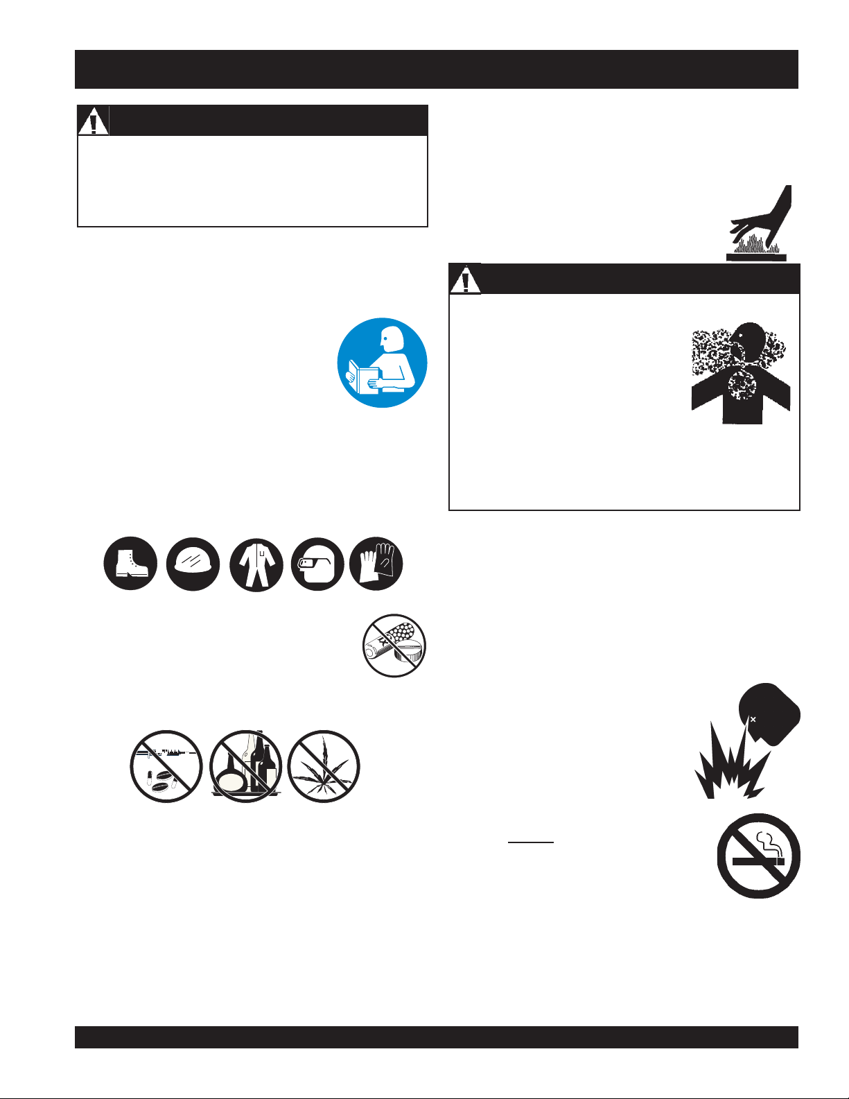
FOR YOUR SAFETY AND THE SAFETY OF OTHERS!
Safety precautions should be followed at all times when
operating this equipment. Failure to read, understand and
comply with the Safety Messages and Operating Instructions
could result in injury to yourself and others.
This Operation Manual has been developed
to provide instructions for the safe and efficient
operation of the Ride-On Trowel. For engine
maintenance information, please refer to the
engine manufacturer's instructions for data
relative to its safe operation.
Before using this Ride-On Trowel, ensure that the operating
individual has read, understands, and complies with all
instructions in this manual.
SAFETY MESSAGE ALERT SYMBOLS
The three (3) Safety Messages shown below will inform you
about potential hazards that could injure you or others. The
Safety Messages specifically address the level of exposure to
the operator, and are preceded by one of three words: DANGER,
WARNING, or CAUTION.
HAZARD SYMBOLS
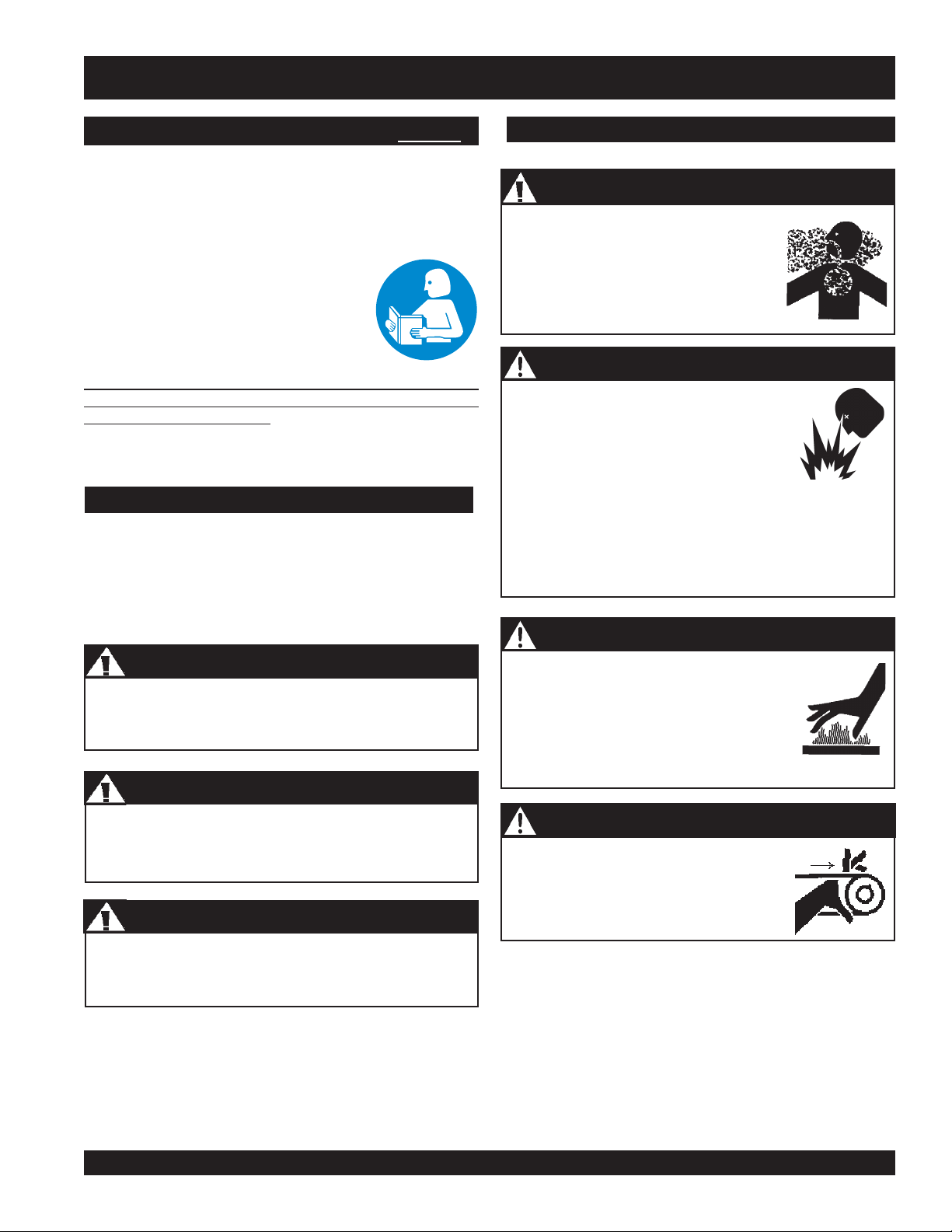
WARNING - Lethal Exhaust Gases
Engine exhaust gases contain poisonous
carbon monoxide. This gas is colorless
and odorless, and can cause death if
inhaled. NEVER operate this equipment
in a confined area or enclosed structure
that does not provide ample free flow air.
DANGER - Explosive Fuel
Diesel Fuel is extremely flammable, and
its vapors can cause an explosion if ignited.
DO NOT start the engine near spilled fuel
or combustible fluids.
DO NOT fill the fuel tank while the engine is running or
hot. DO NOT overfill tank, since spilled fuel could ignite if
it comes into contact with hot engine parts or sparks from
the ignition system. Store fuel in approved containers, in
well-ventilated areas and away from sparks and flames.
WARNING - Burn Hazards
DANGER
You WILL be
NOT follow directions.
You CAN be KILLED or
NOT follow directions.
You CAN be
Potential hazards associated with trowel operation will be
referenced with Hazard Symbols which appear throughout this
manual, and will be referenced in conjunction with Safety
Message Alert Symbols.
KILLED
WARNING
WARNINGWARNING
WARNING
WARNINGWARNING
CAUTION
WARNINGWARNING
WARNING
WARNINGWARNING
INJURED
or
SERIOUSLY INJURED
SERIOUSLY INJURED
if you DO NOT follow directions.
if you DO
if you DO
Engine components can generate extreme
heat. To prevent burns, DO NOT touch
these areas while the engine is running or
immediately after operations. Never
operate the engine with heat shields or heat
guards removed.
CAUTION - Rotating Parts
NEVER operate equipment with covers,
or guards removed. Keep fingers, hands,
hair and clothing away from all moving
parts to prevent injury.
HTN/HTO- 31V • RIDE-ON POWER TROWEL — OPERATION AND PARTS MANUAL — REV. #6 (07/09/07) — PAGE 9
Page 10
HTN/HTO-31V — SAFETY MESSAGE ALERT SYMBOLS
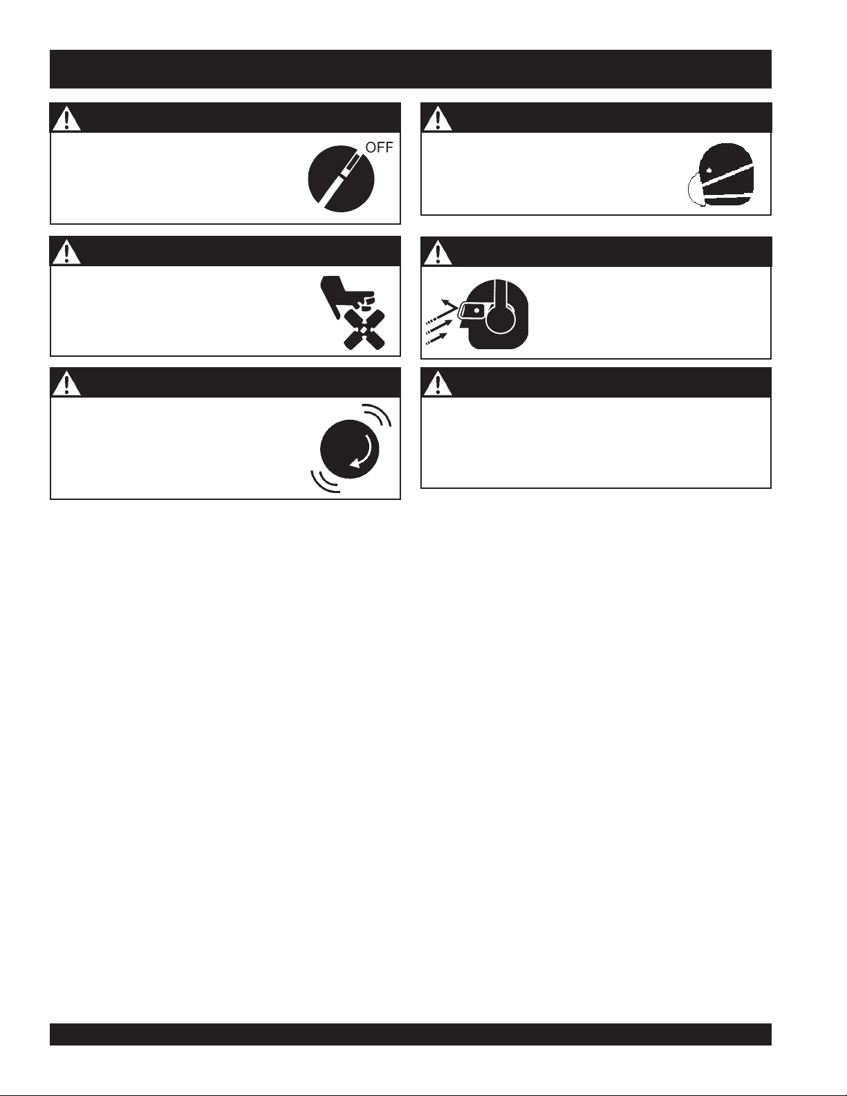
CAUTION - Accidental Starting
ALWAYS place the engine ON/OFF
switch in the OFF position, when
equipment is not in use.
CAUTION - Rotating Blades
ALWAYS keep hands and loose clothing
from rotating blades.
WARNING - Over Speed
NEVER tamper with the factory settings of
the engine governor or settings. Personal
injury and damage to the engine or
equipment can result if operating in speed
ranges above maximum allowable
CAUTION - Respiratory Hazard
ALWAYS wear approved
protection when required.
CAUTION - Sight and Hearing Hazards
ALWAYS wear approved eye and
hearing protection.
CAUTION - Equipment Damage Messages
Other important messages are provided throughout this
manual. Your equipment, other property, or the surrounding
environment could be damaged if you do not follow
instructions.
respiratory
PAGE 10 — HTN 31V
HTN/HTO-31V • RIDE-ON POWER TROWEL — OPERATION AND PARTS MANUAL — REV. #6 (07/09/07) — PAGE 10
Page 11
HTN/HTO-31V — RULES FOR SAFE OPERATION
■
WARNING - Read this Manual
Failure to follow instructions in this manual may lead to serious
injury or even death! This equipment is to be operated by
trained and qualified personnel only! This equipment is for
industrial use only.
The following safety guidelines should always be used when
operating the Ride-On Trowel.
Replace nameplate, operation and safety decals when they
become difficult to read.
■
ALWAYS check for loosened hardware such as nuts and
bolts before starting.
■
NEVER touch the hot exhaust manifold, muffler
or cylinder. Allow these parts to cool before
servicing the equipment. Contact with
components can cause serious burns.
DANGER - Lethal Exhaust Gases
hot
SAFETY
■
DO NOT operate or service this
equipment before you read, understand,
and comply with all safety messages in
this manual. The manual must be kept
available and accessible to the operator.
■
This equipment should not be operated by persons under the
minimum statutory age limit.
■
NEVER operate this equipment without proper protective
clothing, shatterproof glasses, steel-toed boots and other
protective devices required for the job.
■
NEVER operate this equipment when not
feeling well due to fatigue, illness or taking
medicine.
■
NEVER operate the saw under the influence or drugs or
alcohol.
■
■
■
■
■
NEVER operate the equipment in any
enclosed or narrow area where free
flow of the air is restricted. If the air flow
is restricted, it will cause serious
damage to the engine and may cause
injury to people. Remember the engine
gives off
gas. When operating equipment in
confined spaces such as tunnels,
buildings or similar areas, ensure proper air flow to move
engine exhaust away from the operator.
ALWAYS refuel in a well-ventilated area, away from sparks
and open flames.
Topping-off to filler port is dangerous, as it tends to spill fuel.
NEVER use fuel as a cleaning agent.
ALWAYS use extreme caution when working with flammable
liquids. When refueling, STOP the engine. Allow the engine
to cool before adding fuel or performing service and
maintenance functions.
NEVER operate the equipment in an
explosive atmosphere where fumes
are present, or near combustible
materials. An explosion or fire could
result in severe
DEADLY
carbon monoxide
bodily harm or even
death.
■
NEVER use accessories or attachments which are not
recommended by the manufacturer for this equipment.
Damage to the equipment and/or injury to user may result.
■
Manufacturer does not assume responsibility for any accident
due to equipment modifications. Unauthorized equipment
modification will void all warranties. Any modification which
could lead to a change in the original characteristics of the
machine should be made only by the manufacturer who shall
confirm that the machine is in conformity with appropriate
safety regulations.
HTN/HTO- 31V • RIDE-ON POWER TROWEL — OPERATION AND PARTS MANUAL — REV. #6 (07/09/07) — PAGE 11
■
NEVER
Fire or explosion could result from
vapors
■
■
smoke
around or near the machine.
fuel
, or if fuel is spilled on a
NEVER run engine without air filter. Severe engine damage
may occur. Service air filter frequently to prevent carburetor
malfunction.
NEVER place your
while starting or operating this equipment.
feet
or
hot
engine.
hands
inside the guard rings
Page 12

HTN/HTO-31V — RULES FOR SAFE OPERATION
WARNING - Clear Operating Area
ALWAYS make sure that the operating area is clear before
starting the engine.
■
AVOID wearing jewelry or loose fitting clothing that may snag
on the controls or moving parts as this can cause a serious
injury.
■
ALWAYS keep clear of
operating the equipment. Shut down the engine before
performing service or maintenance functions. Contact with
moving parts can cause serious injury.
■
NEVER leave the machine
running.
■
ALWAYS be sure the operator is familiar with proper safety
precautions and operations techniques before using
equipment.
■
ALWAYS keep the work area well organized.
■
ALWAYS clear the work area of any debris, tools, etc. that
would constitute a hazard while the equipment is in operation.
■
No one other than the operator is to be in the working area
when the equipment is in operation.
■
NEVER store the trowel with fuel in the tank for any extended
period of time. Always clean up spilled fuel immediately.
■
NEVER allow passengers or riders on the trowel during
operation.
■
ALWAYS observe all applicable compulsory regulations
relevant to environmental protection, especially, fuel storage,
the handling of hazardous substances, and the wearing of
protective clothing and equipment. Instruct the user as
necessary, or as the user, request this information and
training.
rotating
or
unattended
moving parts
while the engine is
while
Additional Safety Information
A handy safety manual for operating and maintenance personnel
of concrete power trowels produced by the Association of
Equipment Manufacturers (AEM)
can be obtained for a fee by
ordering through their website at
www.aem.org.
Order FORM PT-160.
Lifting the Ride-On Trowel
This ride-on trowel is very
around. Use proper heavy lifting procedures and DO NOT
attempt to lift the ride-on trowel by the guard rings.
This Ride-On Power Trowel is designed to be moved and
handled several ways.
The easiest way to lift the trowel is to utilize the lift loops that are
welded to the frame. These lift loops are located to the left and
right sides of the operator’s seat.
A strap or chain can be attached to these lift loops, allowing a
forklift or crane to lift the trowel up onto and off of a slab of concrete.
The strap or chain should have a minimum 2,000 pounds (1000
kg) lifting capacity and the lifting gear must be capable of lifting
at least this amount.
NEVER stand under or allow anyone else to
stand under the trowel while it is being lifted.
CAUTION - Heavy Lifting
heavy
DANGER - Lifting Trowel
and awkward to move
■
ALWAYS disconnect spark plug wires and battery cables
before attempting any service or maintenance on the ride-on
trowel
■
Reference engine manual for specific information on tuning
up your engine, checking and gaping the spark plugs, etc.
■
ALWAYS store equipment properly when it is not being used.
Equipment should be stored in a clean, dry location out of
the reach of children.
PAGE 12 — HTN 31V
HTN/HTO-31V • RIDE-ON POWER TROWEL — OPERATION AND PARTS MANUAL — REV. #6 (07/09/07) — PAGE 12
Transporting
■
ALWAYS shutdown engine before transporting.
■
Tighten fuel tank cap securely and close fuel cock to prevent
fuel from spilling.
■
Drain fuel when transporting equipment for long distances
or over bad roads.
■
When placing the equipment on a truck-bed for transport,
always
■
If the equipment is being transported via a trailer, make sure
the trailer complies with all local and state safety
transportation laws. Refer to the following "
Precautions"
tie-down the equipment.
Towing Safety
for basic towing techniques.
Page 13

HTN/HTO-31V — RULES FOR SAFE OPERATION
Towing Safety Precautions
CAUTION - Transporting
Conform to
trowel on public roads.
To reduce the possibility of an accident while transporting the
equipment on public roads, always make sure the trailer that
supports the equipment and the towing vehicle are in good
operating condition and that both units are mechanically sound.
The following list of suggestions should be used when towing
your trowel:
■
Make sure the hitch and coupling of the towing vehicle are
rated equal to or greater than the trailer "gross vehicle weight
rating" (GVWR) of 6,000 lbs.
■
ALWAYS inspect the hitch and coupling for wear. NEVER
tow a trailer with defective hitches, couplings, chains, etc.
■
Check the tire air pressure on both towing vehicle and trailer.
Safety Towing Regulations
Trailer tires should be inflated to 50 psi cold
the tire tread wear on both vehicles.
■
ALWAYS make sure the trailer is equipped with "Safety
Chains ".
■
ALWAYS attach trailer's safety chains to towing vehicle
properly.
■
ALWAYS make sure the vehicle and trailer directional,
backup, brake, and trailer lights are connected and working.
■
DO NOT exceed the recommended highway speed when
towing. Unless posted otherwise, do not exceed 45 MPH
highway, and 10 MPH off-road.
■
Use chock-blocks at each wheel when parked to prevent
trailer from rolling.
■
Use the trailer's swivel jack to adjust the trailer height to a
level position while parked.
before transporting
. Also check
Battery
The battery contains acids that can cause injury to the eyes and
skin. To avoid eye irritation,
shielding. Use well-insulated gloves when picking up the battery.
Use the following guidelines when handling the battery.
■
DO NOT drop the battery. Any impact to the battery may
cause it to explode.
■
DO NOT expose the battery to open flames,
sparks, lit cigarettes etc. The battery
contains combustible gases and liquids. If
these gases and liquids come in contact
with a flame or spark an explosion can occur.
■
ALWAYS keep the battery charged. If the
battery is not charged, a buildup of
combustible gas will occur.
■
ALWAYS keep battery cables in good working condition.
Repair or replace all worn cables.
■
ALWAYS disconnect the
performing service on the equipment.
■
Inadequate battery connections may cause poor starting
of the trowel, and create other malfunctions.
■
ALWAYS recharge the battery in a vented air environment
to avoid risk of a dangerous concentration of combustible
gases.
■
DO NOT charge battery if frozen. Battery can explode. When
frozen, warm battery to at least 61°F (16°C).
■
If the battery liquid (dilute sulfuric acid) comes in contact with
clothing or skin
plenty of water.
■
If the battery liquid (dilute sulfuric acid) comes in contact with
your
contact the nearest doctor or hospital and seek medical
attention.
always
wear safety glasses or face
negative battery terminal
, rinse skin or clothing immediately with
eyes
, rinse eyes immediately with plenty of water, then
before
■
Avoid sudden stops and starts. This can cause the trailer to
skid or jack-knife. Smooth, gradual starts and stops will
improve towing.
■
Avoid sharp turns.
■
Trailer should be adjusted to a level position at all times
when towing.
■
Raise and lock trailer wheel stand in the "UP" position when
transporting.
■
Safety towing regulations require to connect and test electric
brake operation and to secure portable power cables in cable
tray with tie wraps.
HTN/HTO- 31V • RIDE-ON POWER TROWEL — OPERATION AND PARTS MANUAL — REV. #6 (07/09/07) — PAGE 13
Page 14

HTN/HTO-31V — RULES FOR SAFE OPERATION
Maintenance Safety
■
ALWAYS shut down the engine and disconnect battery before
performing service or maintenance functions. Contact with
moving parts can cause serious injury.
■
Securely support any equipment components that must be
raised.
■
NEVER lubricate components or attempt service on a running
equipment.
■
ALWAYS allow the equipment a proper amount of time to
cool before servicing.
■
Keep the trowel in proper running condition.
■
Make sure that there is no buildup of concrete, grease, oil or
debris on the machine.
■
Repair damage to the trowel immediately and always replace
broken parts.
■
Dispose of hazardous waste properly. Examples of potentially
hazardous waste are used motor oil, fuel and fuel filters.
■
DO NOT use plastic food containers to dispose of hazardous
waste.
Emergencies
■
■
■
ALWAYS know the location of
the nearest
ALWAYS know the location of the
nearest
Know the phone numbers of the nearest
ambulance, doctor
that a phone or radio is readily available at the
jobsite. If this is not possible, know the location of
the nearest phone. This information will be
invaluable in the event of an emergency.
fire extinguisher
first aid kit
.
and
.
fire department
. Ensure
■
DO NOT pour waste oil or fuel directly onto the ground, down
a drain or into any water source.
■
NEVER store equipment with fuel in the tank for any extended
period of time. Always clean up spilled fuel immediately.
PAGE 14 — HTN 31V
HTN/HTO-31V • RIDE-ON POWER TROWEL — OPERATION AND PARTS MANUAL — REV. #6 (07/09/07) — PAGE 14
Page 15

HTN/HTO-31V — DIMENSIONS/SPECIFICATIONS (TROWEL)
Figure 1. HTN/HTO Dimension Specifications
RETEMARAPNOITACIFICEPS )DRAUGNAV(V13-NTH )DRAUGNAV(V13-OTH
)mc(.ni–htgneL–A )4.642(00.79 )9.432(5.29
)mc(.ni–htdiW–B )721(0.05 )721(0.05
1
)mc(.ni–thgieH–C
gnitarepO).sgk(.sbl–thgieW )354(000,1 )774(240,1
gnippihS).sgk(.sbl–thgieW )445(002,1 )555(422,1
2
ABd–erusserPdnuoS
2
3
s/tf–noitarbiV
s/m(2)
)s/m(MPF–deepSpiTedalB )2.6(6121 )2.6(6121
.P.H–enignE 13 13
)sretil(snollag–knaTleuF )91(5 )91(5
MPR–rotoR 541ot06 541ot06
)mc(.ni–htdiWhtaP )132(19 )422(88
4
liOciluardyH
NOTE:
1. This value does not include seat height. To obtain total
height (seat ) add 4 inches (10.2 cm.).
2. Sound pressure is "A" weighted . Measured at the
operators ear position while the ride-on trowel is operating
at full throttle on concrete in a manner most often
experienced in “
normal
” circumstances. Sound pressure
may vary depending upon the condition of the concrete.
Hearing protection is always recommended.
snoitacificepSseireSOTH/NTH.1elbaT
)711(0.64 )711(0.64
59 59
)5.2(0.8< )5.2(0.8<
086OSIr093101N/PnametihW 086OSIr093101N/PnametihW
3. The vibration level indicated is the maximum RMS (Root
Mean Square) value obtained at the handle grip while
operating the ride-on trowel on curing concrete in a manner
most often experienced in “
normal
” circumstances.
Values were obtained from all three axes of motion. The
values shown represent the maximum RMS value from
these measurements.
HTN/HTO- 31V • RIDE-ON POWER TROWEL — OPERATION AND PARTS MANUAL — REV. #6 (07/09/07) — PAGE 15
Page 16

HTN/HTO-31V — SPECIFICATIONS (ENGINE)
snoitacificepSenignEV13-OTH/NTH.2elbaT
ledoM
epyTenignEenilosaG
srednilyC3
rewoPmpr0063@)Wk1.32(PH13
euqroTmumixaM mpr002
tnemecalpsiD)cc259(.ni.uc1.85
eroB)mm27(.ni9.2
ekortS)mm87(.ni1.3
yticapaCliOenignE)sret
thgieWyrD)gK3.27(.sbl951
)HxWxL(snoisnemiD
nottartS&sggirB
G059draugnaV
2@)mN1.07(.sbltf7.15
il3(.tq2.3
.ni7.91x.ni1.71x.ni6.51
)mm4.105xmm2.344xmm3.134(
PAGE 16 — HTN 31V
HTN/HTO-31V • RIDE-ON POWER TROWEL — OPERATION AND PARTS MANUAL — REV. #6 (07/09/07) — PAGE 16
Page 17

HTN/HTO-31V — GENERAL INFORMATION
HTN/HTO Ride-On Trowel Familarization
The HTN/HTO series Ride-On Power Trowels are designed for
the floating and finishing of concrete slabs. These ride-on trowels
are available in non-overlapping (HTN), and overlapping (HTO)
configurations.
Take a walk around the HTN/HTO Ride-On Power Trowel. Take
note of all the major components like the engine, blades, air
cleaner, fuel system, fuel shut-off valve, ignition switch etc. Check
that there is always oil in the engine, and gear oil in the gear box
assembly.
Read all the safety instructions carefully. Safety instructions will
be found throughout this manual and on the machine. Keep all
safety information in good, readable condition. Operators should
be well trained on the operation and maintenance of the HTN/
HTO Ride-On Power Trowels.
Look at the operator control levers. Grab the control levers and
move them around a bit. Look to see how moving the control
levers causes the gearboxes and frame to move.
Notice the foot pedal which controls the engine speed. Also take
a look at the main driveline of the trowel. Take note and reference
how the belts look, this is the way the belts should look when
adjusted properly.
Before using your HTN/HTO Ride-On Power Trowel, test it on
a flat watered down section of finished concrete. This trial test
run will increase your confidence in using the trowel and at
the same time it will familiarize you with the trowel’s controls
and indicators. In addition you will understand how the trowel
will handle under actual conditions.
Engine
Gearboxes
The HTN/HTO Ride on Power Trowel consist of two separate
gearbox assemblies that are enclosed in rugged cast aluminum
gear cases. The main gear is a high quality bronze and steel
composite. The worm gear is composed of hardened steel.
Cooling fins and fans are integrated into the gearbox to provide
maximum cooling for the gearbox oil. The gearbox casing holds
50% more oil capacity than competitors, which allows more
lubrication to be provided to critical points.
Steering Assist
Dual control levers located in front of the operator's seat are
provided for steering the HTN/HTO Ride on Power Trowel. The
control levers are linked to two spring loaded cylinders.
Push the left control lever forward and pull the right control
lever backward and the trowel will rotate clockwise on
approximately a center axis. Pull the left control lever backward
and push the right control lever forward and the trowel will
rotate counterclockwise.
Constant Velocity Joints (CV-Joints)
Constant velocity joints insure the efficient transfer of power to
the drive shaft and maintains the timing of the gearboxes without
any chance of slippage.
Training
For proper training, please use the “TRAINING CHECKLIST”
located in the front of this manual. This checklist will provide an
outline for an experienced operator to provide training to a new
operator.
The HTN/HTO Ride-On Power Trowel is equipped with a liquid
cooled 31 HP Vanguard gasoline engine. Refer to the engine
owner’s manual for specific instructions regarding engine
operation. This manual is included with the ride-on trowel at the
time of shipping from Whiteman. Please contact your nearest
Multiquip Dealer for a replacement should the original manual
disappear.
Blades
The blades of the ride-on power trowel finish the concrete as
they are swirled around the surface. Blades are classified as
combination (10 or 8 inches wide), finish (6 inches wide). The
HTN/HTO ride-on power trowels are equipped with five blades
per rotor equally spaced in a radial pattern and attached to a
vertical rotating shaft by means of a
HTN/HTO- 31V • RIDE-ON POWER TROWEL — OPERATION AND PARTS MANUAL — REV. #6 (07/09/07) — PAGE 17
spider assembly.
Page 18
HTN/HTO-31V — CONTROLS AND INDICATORS
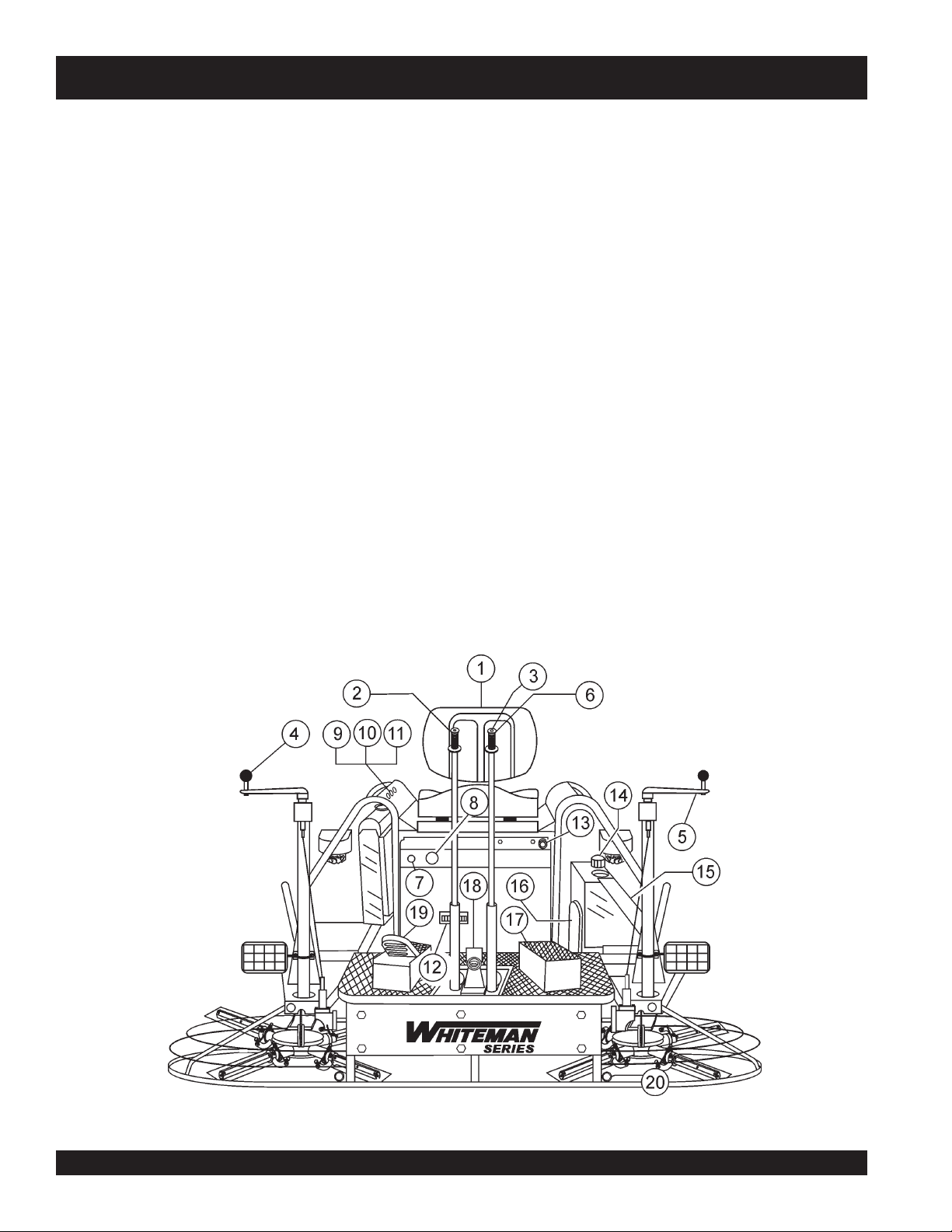
Figures 2 and 3 show the location of the controls, indicators and
general maintenance parts. Each control may perform more than
one function. The functions of each control or indicator is
described below and on the next page.
1. Seat – Place for operator to sit. Engine will not start unless
operator is seated. Seat is adjustable, fore and aft for
operator comfort.
2. Steering Control Lever (right side) -Allows the unit to
move in either a forward, reverse left or right direction.
3. Retardant Spray Control Button – When pressed allows
retardant spray to flow through the spray nozzle located
at the front of the machine.
4. Twin Pitch Control – Adjusts the blade pitch for right side
of the trowel. Turn the crank as marked on its top surface to
increase or decrease blade pitch.
5. Twin Pitch Control – Adjusts the blade pitch for left side
of the trowel. Turn the crank as marked on its top surface to
increase or decrease blade pitch.
6. Steering Control Lever (left side) -Allows the unit to move
in either a forward, reverse left or right direction.
7. Light Switch – When activated, turns on four halogen
lights. Lights offer better visibility when working indoors.
9. Oil Indicator Light - Lights red when oil pressure is low.
10. Water Indicator Light - Lights red when water
temperature is high.
11. Charge Indicator - Lights red when electrical system is
not charging properly.
12. Hour Meter - Indicates number of hours machine has
been in use or hours engine was run.
13. Choke Control Lever. - In cold weather pull this lever
forward about half way to start engine. After engine warms
push knob all the way in.
14. Fuel Gauge/Filler Cap - Indicates the amount of fuel in
the fuel tank. Remove this cap to add fuel.
15. Fuel Tank - Holds 5 gallons of unleaded gasoline.
16. Spare Belt Carrier - Contains 2 spare belts. Belts are
used on the drive pulley.
17. Left Foot Riser – Operator foot rest pedal.
18. Spray Nozzle – Spray nozzle for retardant.
19. Right Foot Pedal – Controls blade speed. Slow blade
speed is accomplished by slightly depressing the foot pedal.
Maximum blade speed is accomplished by fully depressing
the foot pedal.
8. Ignition Switch – With key inserted turn clockwise to
start engine.
20. EZ- Mover Boss – Front -side insertion point for EZ Mover.
Used when the transporting of the trowel is required.
Figure 2. HTN/HTO Controls and Indicators (Front)
PAGE 18 — HTN 31V
HTN/HTO-31V • RIDE-ON POWER TROWEL — OPERATION AND PARTS MANUAL — REV. #6 (07/09/07) — PAGE 18
Page 19
HTN/HTO-31V — CONTROLS AND INDICATORS
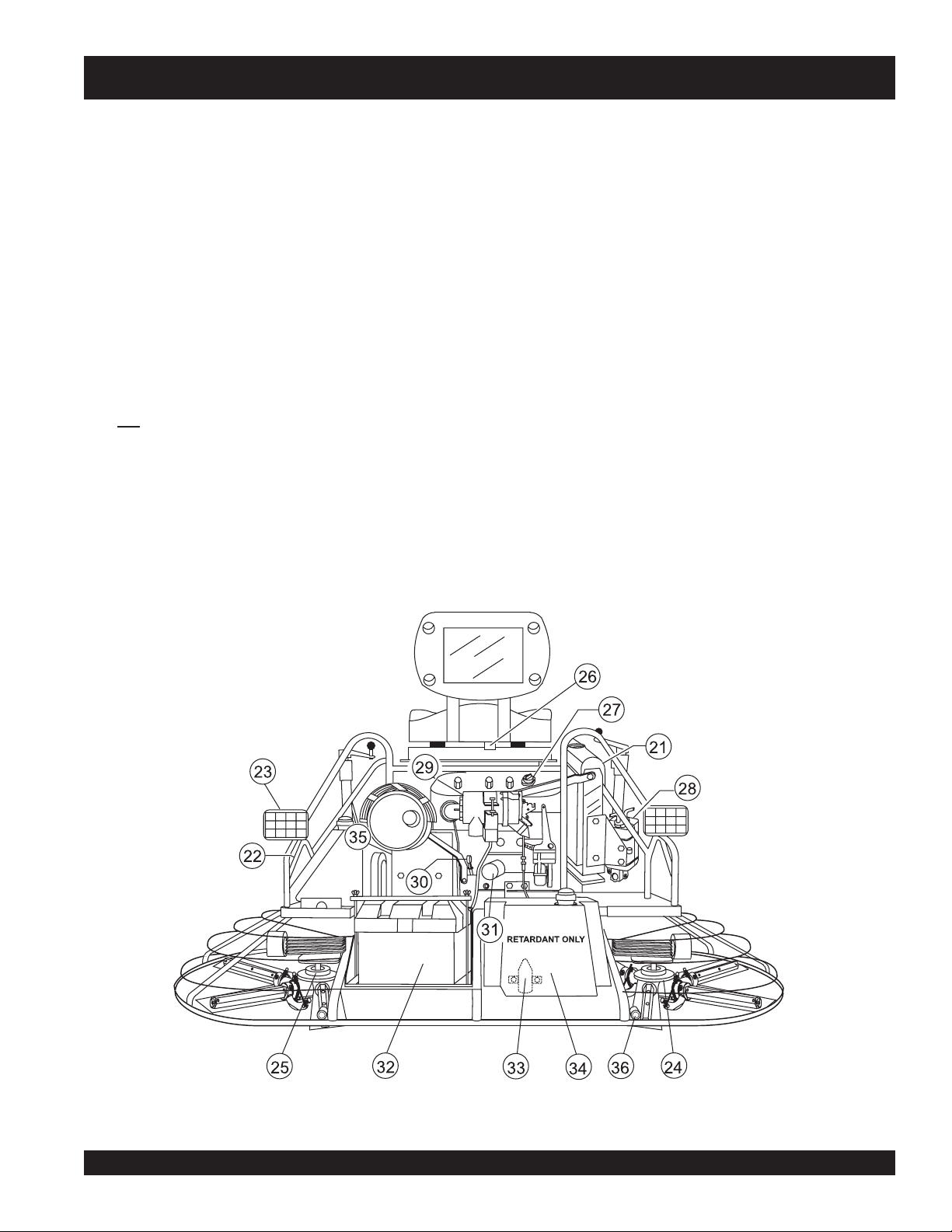
21. Radiator/Filler Cap – Holds coolant or water necessary to
keep engine at a safe operating temperature. Remove this
cap to add water or antifreeze.
22. Lift Loops – Located on both the left and right sides of the
main frame. Used when the trowel must be lifted onto a
concrete slab.
23. Lights – Four 12 volt halogen lights are provided with this
unit.
24. Right-Side Spider – Consists (basic) of trowel arms,
blades, wear plate, and thrust collar etc.
25. Left-Side Spider – Consists (basic) of trowel arms, blades,
wear plate, and thrust collar etc.
26. Safety Kill Switch – Shuts down engine when operator is
not sitting in seat.
27. Engine Oil Filler Cap - Remove this cap to add engine oil.
28. Overflow Bottle - Supplies coolant to the radiator when
radiator coolant level is low. Fill to indicated level as
shown on bottle.
29. Engine Air Filter – Prevents dirt and other debris from
entering the fuel system. Lift locking latch on air filter
cannister to gain access to filter element.
30. Engine Dip Stick – Indicates engine oil level. Add oil as
31. Oil Filter – Provides oil filtering for the engine.
32. Battery – Provides +12V DC power to the electrical system
33. Retardant Spray Motor – Used in conjunction with the
34. Retardant Spray Tank – Holds 5 gallons of retardant.
35. Belt Guard – Encloses V-belts used in conjunction with
36. EZ- Mover Boss – Back- side insertion point for EZ Mover.
The following section is intended as a basic guide to the ride-on
trowel operation, and is not to be considered a complete guide
to concrete finishing. It is strongly suggested that all operators
(experienced and novice) read “
the American Concrete Institute, Detroit Michigan.
required.
left spray control button.
clutch.
Used when the transporting of the trowel is required.
Slabs on Grade
” published by
Figure 3. HTN/HTO Controls and Indicators (Rear)
HTN/HTO- 31V • RIDE-ON POWER TROWEL — OPERATION AND PARTS MANUAL — REV. #6 (07/09/07) — PAGE 19
Page 20
HTN/HTO-31V — ENGINE COMPONENTS
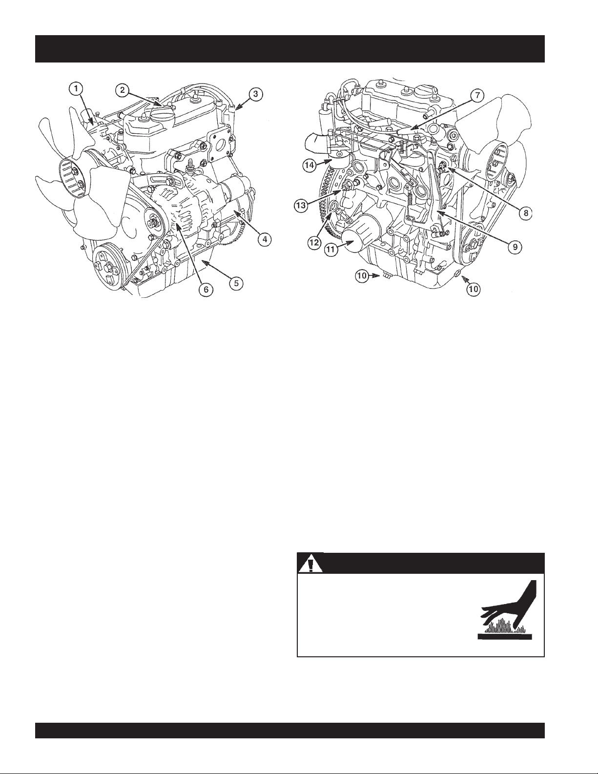
Figure 4. Engine Components
The following refer to the basic engine components for reference
(Figure 4). Refer to the manufacturer's engine manual for instructions
and details of operation and servicing. The engine shown above is
a Briggs & Stratton Vanguard gasoline engine. Operation for
other types of engines may vary somewhat.
1. Thermostat-– Regulates the temperature of the engine
coolant.
2. Oil Filler Cap – Remove to add engine oil.
3. Ignition Coil -– Regulates coolant temperature.
4. Electric Starter – Starts engine when ignition key is rotated
to the "ON" position.
5. Oil Pan – Holds a maximum of 3.2 quarts (3.0 liters) of
motor oil.
6. Alternator - Provides current to the electrical system and
charges the battery.
7. Spark Plug – Provides spark to the ignition system. Set
spark plug gap to 0.028 ~ 0.031 inch (0.6~0.7 mm). Clean
spark plug once a week.
8. Coolant Temperature Sending Unit - Device that
measures coolant temperature.
9. Governor Lever – This lever restricts engine speed (high
idle or low idle) through a speed control device linked to
the accelerator system.
10. Oil Drain – Used to drain crankcase oil. Always dispose of
used oil and oil filters in an environmentally safe manner.
DO NOT allow used oil to drain onto the ground or into a
water runoff drain.
11. Oil Filter – Prevents dirt and other debris from entering the
engine oil.
12. Oil Dip Stick – Remove to check amount and condition of
oil in crankcase.
13. Oil Pressure Sending Unit – Device that measures
engine oil pressure.
14. Carburetor – Low-emission carburetor equipped with an
idle mixture valve with a limiter which allows adjustment.
Engine components can generate extreme heat.
To prevent burns, DO NOT touch these areas
while the engine is running or immediately after
operating. NEVER operate the engine with the
muffler removed.
WARNING - Hot Engine
WARNINGWARNING
WARNING
WARNINGWARNING
PAGE 20 — HTN 31V
HTN/HTO-31V • RIDE-ON POWER TROWEL — OPERATION AND PARTS MANUAL — REV. #6 (07/09/07) — PAGE 20
Page 21
HTN/HTO-31V — SETUP
Trowel Setup Instructions
The purpose of this section is to assist the user in the setting up
of a
NEW
trowel. If your trowel is already assembled (seats,
handles, knobs and battery, then this section can be skipped.
The new ride-on trowel cannot be
put into service until the setup
NOTE
Before packaging and shipping this Whiteman Ride-On Power
Trowel was run and tested at the factory. If there are problems,
please let us know.
Control Handle Assembly
The steering control handles are not attached to the trowel's two
lower handles at the time of shipment. To attach the steering
control handles to the two lower handle assemblies perform the
following:
1. Remove the bolts from the plastic bag tied to the control
towers.
2. Remove all protective wrapping and straps from the control
handles.
3. Slip the top (loose) piece into the base of the
corresponding handle, making sure to line up the holes.
4. Install the bolt through the lined up holes and tighten the
acorn nut onto the threaded end.
5. Pay close attention to any wires that may be inside the control
handles. DO NOT pinch or cut any wires during installation.
6. Inside the plastic bag of parts are two knobs for the pitch
control tower cranks. Install these two knobs onto the tower
crank levers.
Seat Assembly
The seat is not installed on the trowel for shipping purposes.
To attach the seat perform the following:
1. Remove the seat from the protective wrapping.
2. Remove the bolts on the bottom of the seat, and place seat
on the seat mounting plate, then insert the bolts through the
holes or slots on the seat mounting plate and tighten. Attach
wires to seat.
installation instructions are
completed. These pre-setup
instructions only need to be
performed at the time of unpacking
NEW
trowel.
a
NOTE
on tracks, similar to an automobile seat. This seat can be adjusted
fore and aft via the control lever under the front of the seat.
Battery Setup
This trowel was shipped with a wet charged battery. This battery
may need to be charged for a brief period of time as per the
manufacturer instructions.
Use all safety precautions specified by the battery
manufacturer when working with the battery.
Flammable, explosive gas. (produces
hydrogen gas while charging or during
operation). Keep area around battery well
ventilated and keep from any fire source.
Shock or Fire due to electric shortcircuit. Disconnect battery cables
before inspecting electrical system
and never "spark" battery terminals to
test for charge.
To install the battery on the trowel, make sure that the battery is
well seated in the battery box and the terminals are properly
connected. Close the plastic battery box cover and secure the
NOTE
There are two types of seats,
depending on what type of trowel
you have. J and B series trowels
have slots on the seat mounting
plate that allow fore and aft
adjustment of the seat. H-series
trowels have a seat that is mounted
WARNING - Battery Safety
Battery electrolyte contains corrosive,
toxic chemical. (dilute sulfuric acid).
Avoid contact with eyes and skin.
battery box.
ALWAYS be sure the battery
cables are properly connected to
the battery terminal. The RED cable
is connected to the positive terminal
of the battery, and the BLACK cable
is connected to the negative
terminal of the battery.
HTN/HTO- 31V • RIDE-ON POWER TROWEL — OPERATION AND PARTS MANUAL — REV. #6 (07/09/07) — PAGE 21
Page 22
HTN/HTO-31V — INSPECTION
1. Check and clean battery terminals for corrosion.
2. Check and keep battery electrolyte between upper and
lower limits indicated on the battery. Never operate or
recharge without sufficient fluid in the battery.
3. Never attempt to charge a battery that is frozen. The battery
can explode unless first allowed to thaw.
4. Disconnect the negative terminal ( - ) of the battery during
storage. If unit will be stored where ambient temperature
will drop to -15
warm, dry place.
This section is intended to assist the operator with the initial
start-up of the HTN/HTO series Ride-On Power trowel. It is
extremely important that this section be read carefully before
attempting to use the trowel in the field.
DO NOT use your ride-on power trowel until this section is
thoroughly understood.
WARNING - Damage and Injury
WARNINGWARNING
WARNING
WARNINGWARNING
Failure to understand the operation of the HTN/HTO-31V
Ride-On Power Trowel could result in severe damage to the
trowel or personal injury.
o
C or less, remove and store battery in a
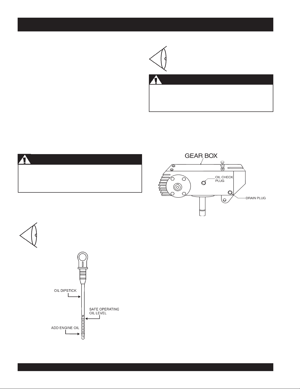
Gearbox Oil Level
Use caution when removing plugs on the gearbox, there are
two of them. Removal of the bottom most plug (Drain Plug) will
drain the oil in the gearbox.
2. The level of oil in the gearbox should just reach the bottom
of the fill plug hole. The fill hole plug is located
approximately half way up the side of the gearbox. If
needed, refill with specially formulated Whiteman gearbox
lubricant P/N 10139 or ISO 680 oil.
1. Check the gearbox oil level in both gearboxes
by removing the plug located on the side of
the gearbox. See Figure 6.
CAUTION - Gearbox Plugs
WARNINGWARNING
WARNING
WARNINGWARNING
See Figures 2 and 3 for the location of any control or indicator
referenced in this manual.
Engine Oil Level
1. Pull the engine oil dipstick from its holder.
2. Determine if engine oil is low (Figure 5), add
correct amount of engine oil to bring oil level
to a normal safe level.
Fuel
To determine if the engine fuel is low, remove the cap from the
fuel tank and visually inspect the fuel level. If fuel level is low, fill
with unleaded gasoline. Handle fuel safely. Motor fuels are highly
flammable and can be dangerous if mishandled. DO NOT smoke
while refueling. Do not attempt to refuel the ride-on trowel if the
engine is hot or running.
Figure 6. Gearbox Oil Plugs
Figure 5. Engine Oil Dipstick
PAGE 22 — HTN 31V
HTN/HTO-31V • RIDE-ON POWER TROWEL — OPERATION AND PARTS MANUAL — REV. #6 (07/09/07) — PAGE 22
Page 23

HTN/HTO 31V — OPERATION
Important Information Before You Start
1. This
ride-on trowel
switch"
Remember the engine will not start unless an operator is
sitting in the operator’s seat. The weight of an operator
depresses an electrical switch which will allow the engine
to start.
. This switch is located beneath the seat assembly.
CAUTION - Kill Switch
WARNINGWARNING
WARNING
WARNINGWARNING
is equipped with a safety
"safety stop
2. Keep your foot OFF the gas pedal. If the engine is cold,
adjust the choke but in all circumstances, start the engine
at idle (without touching gas pedal).
3. Insert the
4. Turn the ignition key clockwise to the (start) position. The
oil
NEVER disable or disconnect the "safety stop switch".
It is provided for the operator's safety and injury or death
may result if it is disabled, disconnected or improperly
maintained.
2. The safety stop switch should be used to stop the engine
after every use. Doing this will verify the switch is working
properly thus providing safety for the operator. Remember
to turn the key to the “OFF” position after stopping the
machine. Not doing so will drain the battery.
3. The right foot pedal (Figure 7) controls blade and engine
speed. The position of the foot pedal determines the blade
speed. Slow blade speed is obtained by slightly depressing
the pedal. Maximum blade speed is obtained by fully
depressing the pedal.
Figure 8. Oil and Charge Indicator Lights
5. Turn ignition key fully clockwise and listen for engine to
start. Once engine has started release ignition key.
6. If the engine fails to start in this manner, consult the engine
owner's manual supplied with the trowel.
ignition key
and charge indicator lights (Figure 8) should be on.
into the ignition switch .
7. Test the safety kill switch by standing up briefly. The switch
under the seat should cause the engine to stop. If the kill
switch fails to shut down the engine. Turn off the engine
with the key switch and fix the safety kill switch. See
Troubleshooting Chart for possible problems.
8. Repeat this section a few times to get fully acquainted with
the engine starting procedure.
Figure 7. Blade Speed Control Foot Pedal
Starting the Engine
1. With one foot on the ground and the other foot placed on
the trowel's platform, grab the frame near the seat and lift
yourself onto the trowel. Sit in the operator's seat and ensure
the control handles, foot pedal and control panel items can
be comfortably accessed.
9. Let the engine idle for 3-5 minutes. If choke is applied,
push the choke to the open position as soon as the engine
will run smoothly.
HTN/HTO- 31V • RIDE-ON POWER TROWEL — OPERATION AND PARTS MANUAL — REV. #6 (07/09/07) — PAGE 23
Page 24
HTN/HTO-31V — OPERATION
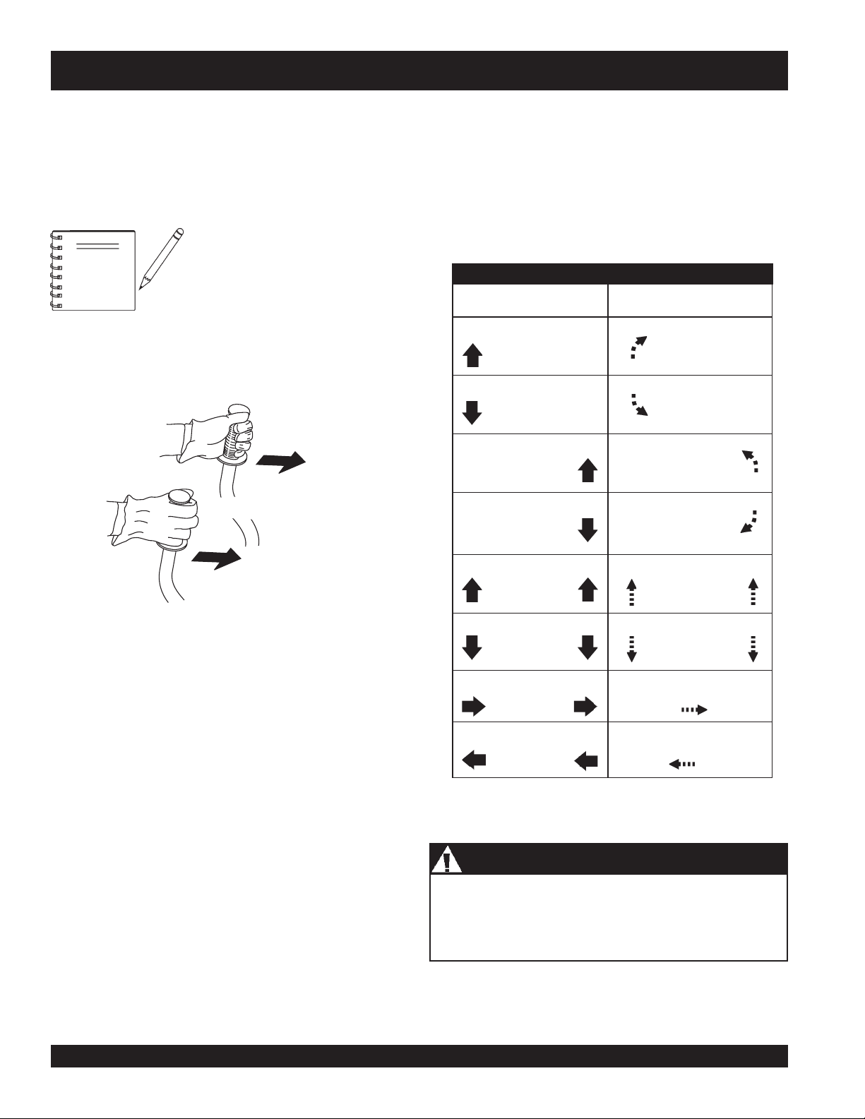
Steering
Two control levers located in front of the operator’s seat
provide directional control for the trowel. Table 3 illustrates
the various directional positions of the joysticks and their
effect on the ride-on trowel.
6. Try adjusting the pitch of the blades. This can be done with
the ride-on trowel stopped or while the trowel is moving,
whatever feels comfortable. Test the operation of optional
equipment like retardant spray and lights if equipped.
7. Push both the left and right joysticks backward and repeat
steps 3 through 6 while substituting the word reverse for
forward.
All directional references with respect
NOTE
to the steering control levers are from
the
operator’s
seat position.
Table 3. Control Lever Directional Positioning
CONTROL LEVER
Move Control Lever
1. Push both the left and right control levers forward. See
Figure 9.
LEFT CONTROL LEVER
FORWARD DIRECTION
RIGHT CONTROL LEVER
Figure 9. Left and Right Control Levers
Move Control Lever
Move Control Lever
Move Control Lever
Move Control Levers
Move Control Lever
& DIRECTION
LEFT
FORWARD
LEFT
BACKWARD
RIGHT
FORWARD
RIGHT
BACWARD
BOTH
FORWARD
BOTH
BACKWARD
RESULT
Causes only the
leftsideofthe
ride-on trowel to
move forward.
Causes only the
leftsideofthe
ride-on trowel to
move backward.
Causes only the
right side of the
ride-on trowel to
move forward.
Causes only the
right side of the
ride-on trowel to
move backward.
Causes the ride-on trowel
to move forward in
a straight line.
Causes the ride-on trowel
to move backard in
a straight line.
2. With your right foot quickly depress the right foot pedal
halfway. Notice that the ride-on power trowel begins to
BOTH
to the RIGHT
Causes the ride-on trowel
to move to the right.
Move Control Levers
move in a forward direction. Return both joystick
controls to their neutral position to stop forward
movement, then remove your right foot from the right
BOTH
to the LEFT
Causes the ride-on trowel
to move to the left.
Move Control Levers
foot pedal.
3. Practice holding the machine in one place as you
increase blade speed. When about 75% of maximum
blade speed has been reached, the blade will be moving
at proper finishing speed. The machine may be difficult
CAUTION
- Obstructions
to keep in one place. Trying to keep the ride-on trowel
stationary is a good practice for operation.
Trowel arms can be damaged by rough handling or by
striking exposed plumbing or forms while in operation.
4. Practice maneuvering the ride-on trowel using the
information listed in Table 3. Try to practice controlled
ALWAYS
look-out for objects which might cause damage
to the trowel arms.
motions as if you were finishing a slab of concrete.
Practice edging and covering a large area
HTN/HTO-31V • RIDE-ON POWER TROWEL — OPERATION AND PARTS MANUAL — REV. #6 (07/09/07) — PAGE 24
.
PAGE 24 — HTN 31V
Page 25
HTN/HTO-31V — MAINTENANCE (ENGINE)
MAINTENANCE
When performing any maintenance on the trowel or engine,
follow all safety messages and rules for safe operation stated at
the beginning of this manual.
At the front of the book there is a “Daily Pre-Operation Checklist”.
Make copies of this checklist and use it on a daily basis.
Daily Maintenance
Thoroughly remove dirt and oil from the engine and control area.
Clean or replace the air filter element as necessary. Check and
retighten all fasteners as necessary.
Perfor m the engine maintenance procedures as indicated on the
preceeding pages.
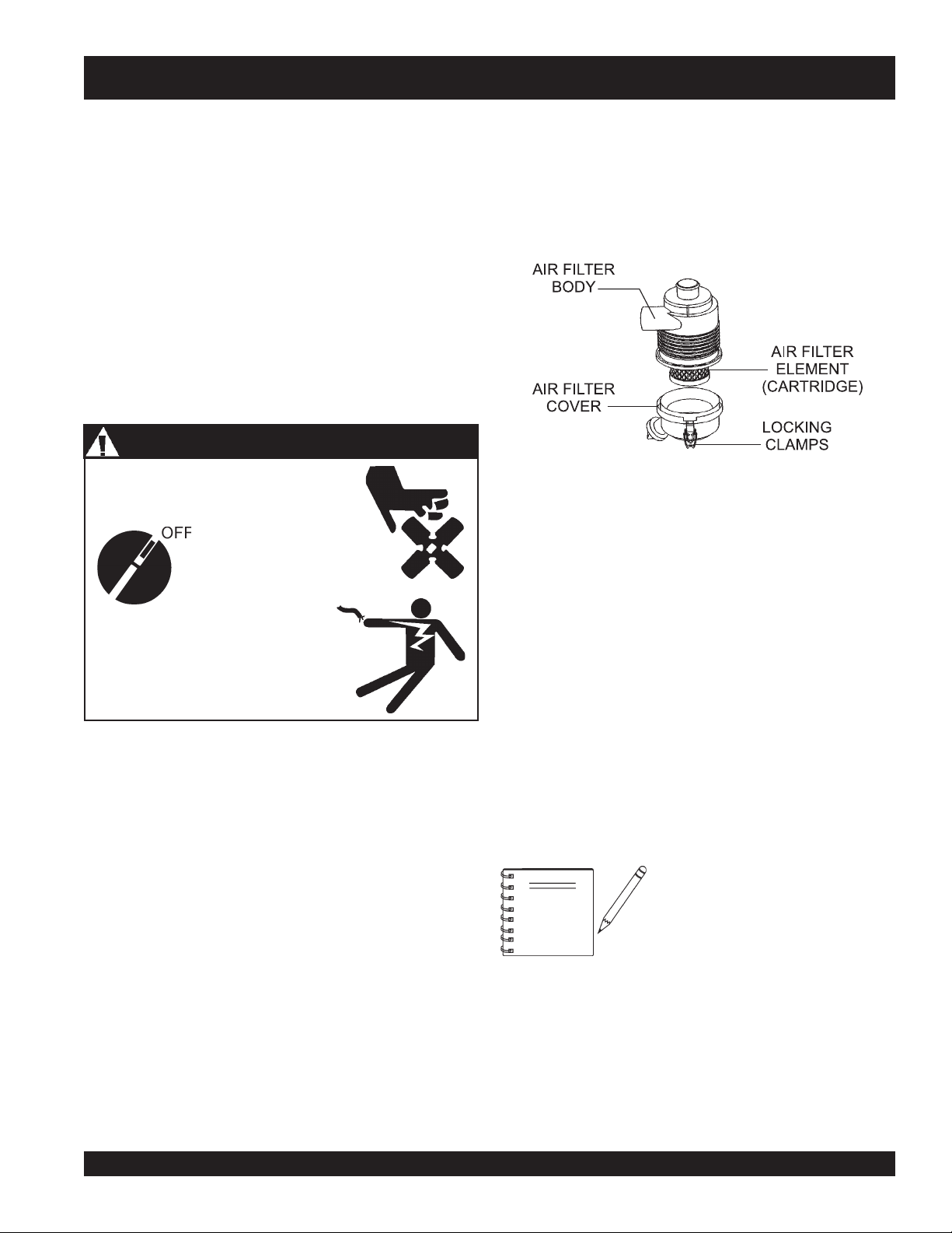
WARNING
Accidental starts can cause severe injury
or death.
- Accidental Starting
ALWAYS place the ON/OFF
switch in the OFF position.
Air Filter (As Required)
Thoroughly remove dirt and oil from the engine and control area.
Clean or replace the air cleaner elements as necessary. Check
and retighten all fasteners as necessary.
1. Release the two latch clamps (Figure 10) from the air
cleaner cover, and remove the cover.
Figure 10. Air Cleaner Components
2. Remove the air filter cartridge from the cover.
3. Inspect the air filter element, replace if necessary.
4. To clean the air filter element (cartridge), blow compressed
air (not to exceed 30 psi (207 kPa, 2.1 kgf/cm
filter element from the air cleaner case side.
2
) through the
5.
NEVER!
Disconnect and ground spark plug
leads and disconnect negative
battery cable from battery before
servicing.
Maintenance Schedule
1. Check and retighten all fasteners as necessary.
fibers. If the air filter element (cartridge) is excessively dirty,
replace element.
6. Wipe dirt from the inside of the air cleaner body and cover,
using a moist cloth. Be careful not to let any dirt or debris to
enter the air chamber that leads to the carburetor.
7. Reinstall the air filter element (cartridge) back into the air
cleaner cover. Securely latch the two locking clamps on
the air cleaner cover
Daily (8-10 Hours)
1. Check the fluid levels in the engine and gearboxes, fill
as necessary. Check air filter. See section on air filter
servicing.
Weekly (30-40 Hours)
NOTE
1. Relube arms, thrust collar and steering links.
2. Replace blades if necessary.
3. Check and clean or replace the engine air filter as
necessary. (See following section on air Filter
Maintenance.)
4. Replace engine oil and filter as necessary. (See following
section on Oil and Filter.)
try to brush off dirt; brushing will force dirt into the
If trowel is used is in severe windy or
dusty areas, service air filter more
frequently to prevent damage to the
engine.
HTN/HTO- 31V • RIDE-ON POWER TROWEL — OPERATION AND PARTS MANUAL — REV. #6 (07/09/07) — PAGE 25
Page 26
HTN/HTO-31V— MAINTENANCE (ENGINE)
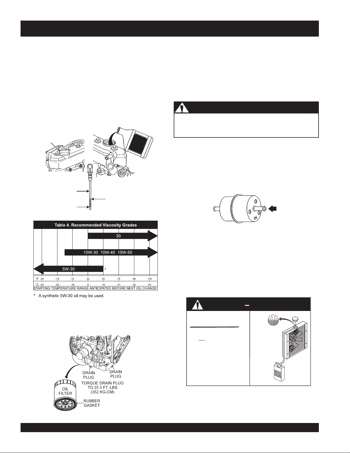
Changing Engine Oil (200 Hours)
1. Change the engine oil after the first 50 hours of use,
then change every 6 months or 200 hours. Drain oil
while engine is warm.
2. Remove the oil filler cap (Figure 11), and fill engine
Oil And Fuel Lines
■
Check the oil and fuel lines and connections regularly for
leaks or damage. Repair or replace as necessary.
■
Replace the oil and fuel lines every two years to maintain
the line's performance and flexibility.
crankcase with recommended type oil as listed in Table 4.
Fill to the upper limit (F) of dipstick.
Fuel Filter (600 Hours)
3. Reinstall oil filler cap, start engine and run at idle for 5
minutes. Stop engine. Recheck oil level. Add oil if
necessary. DO NOT over-fill.
OIL FILLER
CAP
MOTOR
OIL
Drain fuel tank or close fuel shut-off valve before replacing
fuel filter.
1. Replace the engine fuel filter (Figure 13) every 600
hours.
2. To prevent the spillage of fuel which could cause a fire
or an explosion. Always make sure fuel hose clamps
are secured tightly and that fuel flows in the correct
ENGINE OIL
DIPSTICK
ADD ENGINE
OIL
F
L
SAFE OPERATING
ENGINE OIL LEVEL
Figure 11. Adding Engine Oil
direction as indicated by arrow.
CAUTION - Fuel Filter Replacement
WARNINGWARNING
WARNING
WARNINGWARNING
Coolant (Antifreeze/Summer Coolant/Water)
1. Briggs and Stratton recommends antifreeze/summer
coolant for use in their engines, which can be purchased
in concentrate (and mixed with 50% demineralized
water) or pre-diluted.
2. Check coolant level daily (Figure 14) and change yearly.
1. Change the engine oil filter (Figure 12) after the first 50
hours of use, then change every 6 months or 200 hours.
2. Be sure to coat the
with clean engine oil.
rubber gasket
of the new oil filter
CHECK DAILY
1. Maintain water/coolant level
2. Maintain reserve tank water/
3. Add coolant when reserve
Figure 13. Fuel Filter
CAUTION
at of radiator coils.
top
coolant level between H and
L mark. Use a mixture of
50/50 Anti-Freeze/Water.
tank is low (L). Fill to the H
mark with Anti-Freeze/Water.
Check Coolant
WATER
COOLANT
LEVEL
H
RESERVOIR
L
TANK
Figure 14. Check Coolant Level
Figure 12. Engine Oil FIlter
PAGE 26 — HTN 31V
HTN/HTO-31V • RIDE-ON POWER TROWEL — OPERATION AND PARTS MANUAL — REV. #6 (07/09/07) — PAGE 26
Page 27
HTN/HTO-31V — MAINTENANCE (ENGINE/TROWEL)
Radiator/Cooling System
1. Check and clean radiator fins.
2. Check cooling water.
3. Check radiator hoses for fatigue or cracking.
4. Check radiator cap sea.
Refer to your engine manual for additional information.
Checking Drive V-Belts
WARNING - BURN HAZARDS
If adding coolant/antifreeze mix to the
radiator, DO NOT remove the radiator cap
until the unit has completely cooled. The
hot!
possibility of
coolant exists which
can cause severe burns.
Day-to-day addition of coolant is done from the reservoir
tank. When adding coolant to the radiator, DO NOT remove
the radiator cap until the unit has completely cooled. Make
sure the coolant level in the reservoir tank is always between
the "H" and the "L" markings.
In order to inspect the the drive V-belts for signs of wear or,
belt adjustment the V-belt guard cover (Figure 17) must be
removed.
CAUTION - Rotating Parts/V-Belt Safety
NEVER perform service on the trowel or
insert hands or tools into the belt area
while the engine is running.
Figure 16. Spark Plug Gap
Engine Fan Belt (Yearly)
1. Check the condition of the fan belt periodically, if worn
or damage replace immediately.
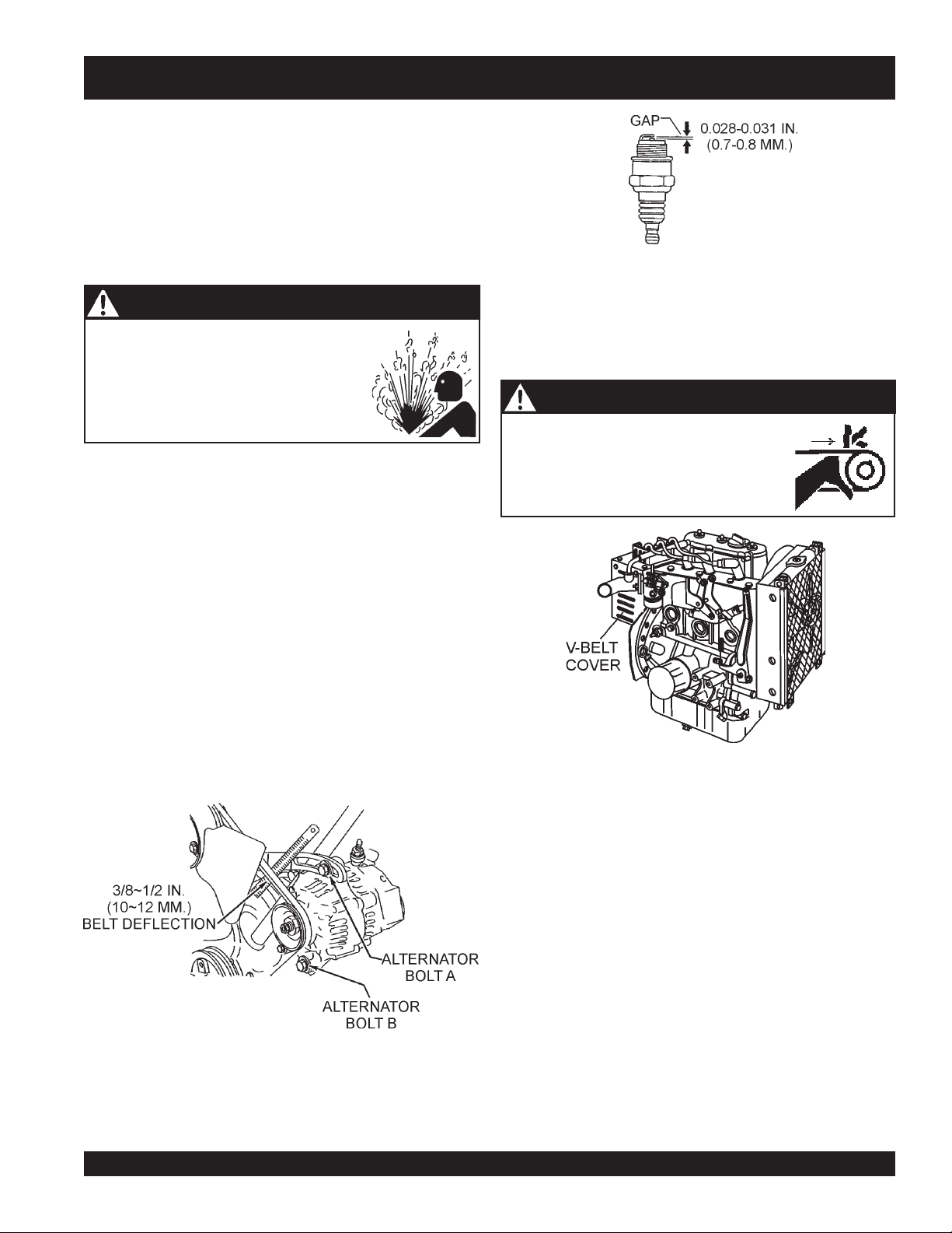
2. For long lasting V-belt life, check fan belt (Figure 15)
for correct tension. There should be between 3/8~1/2inch (10~12 mm) deflection at the center point of the Vbelt between the fan and the alternator.
3. Torque alternator bolt A to 14 ft-lbs (195 kg-cm) and
torque alternator bolt B to 45 ft-lbs (622 kg-cm).
The first indication of belt wear is reduced blade speed despite
the engine running at full speed. Visually inspect the belts
for signs of damage or excessive wear.
Always replace the belt guard after inspecting, adjusting or
replacing the belts.
Drive Belt Tension Adjustment Procedure
Belt tension is adjusted by sliding the entire engine fore and
aft on the trowel, The motor mount plate is slotted to allow
this motion.
Figure 17. V-belt Cover Removal
Figure 15. V-Belt Deflection
To adjust the belt tension, loosen the four engine mounting
bolts, slide the engine forward to tighten the belts or slide
Spark Plug (Yearly)
1. Remove and clean the spark plug (Figure 16), then adjust
the spark gap to 0.028 ~0.031 inch (0.6~0.7 mm).
HTN/HTO- 31V • RIDE-ON POWER TROWEL — OPERATION AND PARTS MANUAL — REV. #6 (07/09/07) — PAGE 27
the engine towards the rear of the machine to loosen the
belts. Make sure to tighten the engine mounting bolts after
setting the belt tension.
Page 28
HTN/HTO-31V — MAINTENANCE (TROWEL)
Belt Changing Procedure
The belts need to be changed as soon as they show signs
of wear. Remember that all belts should be changed at the
same time. Do not reuse a belt under any circumstances.
Indications of excessive belt wear are fraying, squealing
when in use, belts that emit smoke or a burning rubber smell
when in use.
Under normal operating conditions, a set of belts may last
approximately six months. If you trowel is not reaching this
kind of life span for belts, there are some things to check
when you replace a set of belts.
Check to ensure that the belts are tensioned correctly. Next,
check to make sure that the lower drive pulley (Figure 18) is
aligned properly.
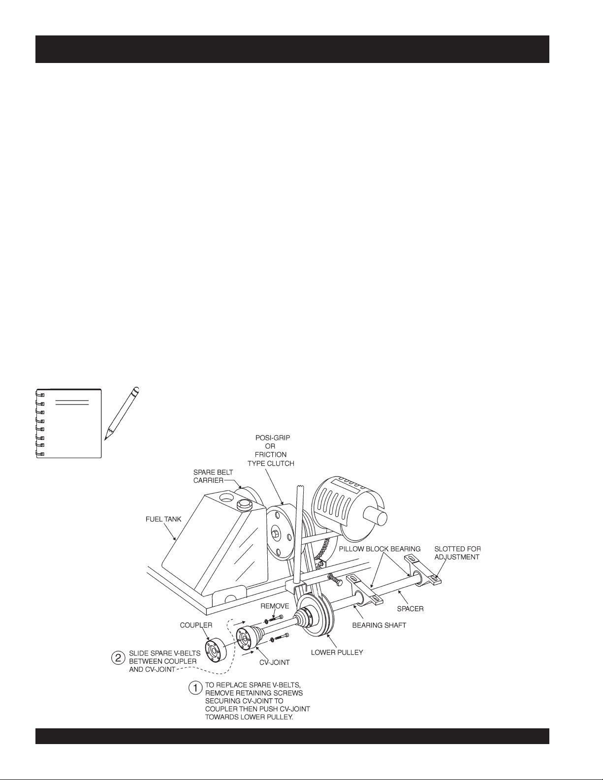
Your machine is equipped with a spare belt carrier (Figure 18). It
is located opposite the clutch, mounted on the fuel tank. Make
sure that there are belts in the carrier before the trowel is placed
on a slab to finish concrete.
To install new belts from the spare belt carrier, first cut off
the old belts. Next, remove the spare belt carrier by
unscrewing the two bolts that attach it to the fuel tank.
Make sure that there are belts in
NOTE
the belt carrier before the trowel is
placed on a slab to finish concrete.
The next step is to loosen the four engine mounting bolts
and slide the engine toward the rear of the trowel. Slide the
first belt over the clutch and place it on the upper drive pulley,
then pull it down and place it on the lower drive pulley. Repeat
this procedure for the second belt.
Realign the engine as described in the Belt Tension
Adjustment Procedure, and replace the belts in the spare
belt carrier.
Replacing Spare Belts
.
After the spare set of belts has been installed on the clutch
pulley, it will be necessary to replace the spare set of belts
that were in the spare belt carrier.
To replace a spare set of belts, be prepared to disassemble
driveline
the
The driveline is located directly under the spare belt carrier.
There are three bolts that need to be removed that will
disconnect the CV-joint from the gearbox coupler. Reference
Figure 18.
Once the CV-joint has been separated from the gearbox
coupler, push the CV-joint inward so that a gap exist between
the coupler and the CV-joint. Slide the replacement belts
between this gap, and place them onto the spare belt carrier.
Secure the spare belt carrier to the fuel tank.
.
Figure 18. Belt Changing Diagram
PAGE 28 — HTN 31V
HTN/HTO-31V • RIDE-ON POWER TROWEL — OPERATION AND PARTS MANUAL — REV. #6 (07/09/07) — PAGE 28
Page 29
HTN/HTO-31V — MAINTENANCE (TROWEL)
■
WARNING - BURN HAZARDS
ALWAYS allow the engine to cool before
servicing. NEVER attempt any maintenance
hot!
work on a
engine.
Trowel Maintenance Schedules
Weekly (50-60 Hours)
1. Relube arms, thrust collar and clutch.
2. Replace blades if necessary.
Monthly (200-300 Hours)
1. Remove, clean, reinstall and relube the arms and thrust
collar. Adjust the blade arms.
2. Replace gearbox lubricant after the first 100 hours of
operation. Replace every 500-600 hours thereafter.
3. Check drive belt for excessive wear. (Refer to following
section on Drive Belt maintenance.)
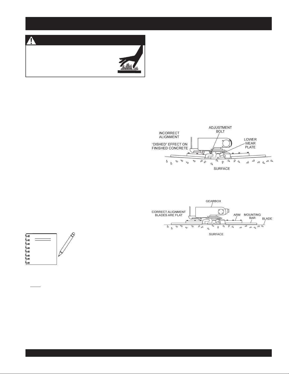
Pitch the blades as flat as possible and look at the
adjustment bolts
the
lower wear plate
them is not making contact, some adjustment will be
necessary.
■
Is the machine wearing out blades unevenly (i.e. one blade
is completely worn out while the others look new)?
Figure 19 below illustrates a "
trowel arms
touching (0.10" max. clearance) lower wear plate. All alignment
bolts should be spaced the same distance from the lower wear
plate.
. They should all barely make contact with
on the spider. If you can see that one of
worn spider bushings or bent
". Check to see that adjustment bolt is barely
4. Remove, clean, reinstall clutch.
Yearly (2000-2500 Hours)
1. Check and replace if necessary the arm bushings, and
thrust collar bushings, shaft seals and belts.
Figure 20 below illustrates the "
plate (as shipped from the factory).
2. Check pitch control cables for wear.
3. Replace gearbox lubricant.
Trowel Arm Adjustment Procedure
The following procedure should be
followed to adjust trowel arms when
NOTE
it becomes apparent that the trowel
is finishing poorly or in need of
routine maintenance.
Start engine, and bring trowel blades up to full speed and look
for the following conditions:
■
Does the trowel have a perceived rolling or bouncing
motion when in use?
A
level
, clean area to test the trowel prior to and after is
essential. Any uneven
spots
in the floor or debris under the
■
Look at the trowel while it is running, does the guard ring
“rock up and down” relative to the ground?
trowel blades will give an incorrect perception of adjustment.
Ideally, a 5-foot by 5 foot three-quarter inch thick
flat
steel
plate should be used for testing.
Figure 19. Worn Spider Plate
correct alignment
Figure 20. Correct Spider Plate Alignment
" for a spider
To determine which blades need adjustment, place the trowel
in the test area (three-quarter inch thick plate) and look for
the following conditions:
HTN/HTO- 31V • RIDE-ON POWER TROWEL — OPERATION AND PARTS MANUAL — REV. #6 (07/09/07) — PAGE 29
Page 30
HTN/HTO-31V — MAINTENANCE (TROWEL)
Spider Removal (Disassembly)
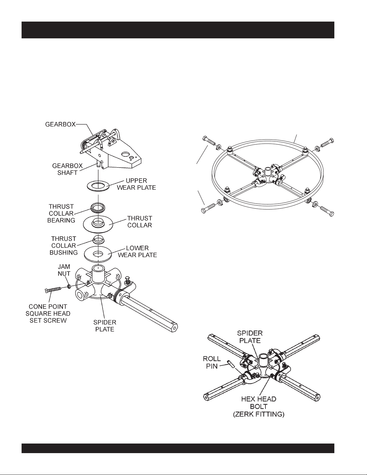
b. Loosen the jam nut and cone point square head set
1. Once it is determined that an adjustment is required,
remove the spider assembly from the gearbox shaft as
follows:
a. Locate cone point square head set screw (Figure 21)
and attached jam nut found on the side of the spider
c. If the trowel is equipped with an outer stabilizer ring
assembly.
REMOVE
TO FREE
SPIDER
ASSEMBLY
screw, and carefully lift the
upper trowel assembly
off
of the spider assembly. A slight tap with a rubber mallet
may be necessary to dislodge the spider from the main
shaft of the gearbox.
(Figure 21), remove the four bolts at the end of each
spider arm.
STABILIZER
RING
Figure 21. Spider/Gearbox Removal
Figure 22. Stabilizer Ring
d. Examine stabilizer ring for out of round or bends. If ring
is damaged, replace ring. If ring is found to be correct with
no damage, set aside.
Trowel Arm Removal
1. Each trowel arm is held in place at the spider plate by a hex
head bolt (zerk grease fitting) and a roll pin. Remove both the
hex head bolt and the roll pin (Figure 23) from the spider
plate.
2. Remove the trowel arm from the spider plate.
Figure 23. Removing Roll Pin
and Zerk Grease Fitting
PAGE 30 — HTN 31V
HTN/HTO-31V • RIDE-ON POWER TROWEL — OPERATION AND PARTS MANUAL — REV. #6 (07/09/07) — PAGE 30
Page 31

HTN/HTO-31V — MAINTENANCE (TROWEL)
3. Should the trowel arm inserts (bronze bushing ) come out
with the trowel arm, remove the bushing from the trowel arm
and set aside in a safe place. If the bushing is retained inside
the spider plate, carefully remove the bushing.
4. Examine the bronze trowel arm bushing insert (Figure 24),
clean if necessary. Replace bushing if out-of-round or worn.
Trowel Arm Flatness Test
1. Using a piece of 3/4 inch thick steel plate or any surface which
true
Figure 24. Bronze Bushings
Trowel Blade Removal
1. Remove the trowel blades from the trowel arm by removing
the three hex head bolts (Figure 25) from the trowel arm. Set
blades aside.
is
flatness.
2. Check each of the six sides of the trowel arm (hex section).
A feeler gauge of .004" (0.10 mm) should not pass between
the flat of the trowel arm and the test surface along its length
on the test surface (Figure 46, A) .
Figure 26. Typical Trowel Arm
and
flat
, check all
six sides
of each trowel arm for
Figure 25. Trowel Blades
2.
Wire brush
trowel arm. Repeat this for the remaining three arms.
any build-up of concrete from all six sides of the
Figure 27. Trowel Arm Flatness Test
3. Next, check the clearance between the round shaft and
Checking Trowel Arm Straightness
Trowel arms can be damaged by rough handling, (such as
dropping the trowel on the pad), or by striking exposed
plumbing, forms, or rebar while in operation. A bent trowel
arm will not allow the trowel to operate in a smooth fluid
rotation. If bent trowel arms are suspect, check for flatness
as follows, refer to Figures 26 and 27.
HTN/HTO- 31V • RIDE-ON POWER TROWEL — OPERATION AND PARTS MANUAL — REV. #6 (07/09/07) — PAGE 31
the test surface as one of the flat hex sections of the arm
rests on the test surface. Rotate the arm to each of the
flat hex sections and check the clearance of the round
shaft. Use a feeler gauge of .005" (0.127 mm). Each
section should have the
same clearance
between the
round of the trowel arm shaft and the test surface (Figure
27, B) .
Page 32

HTN/HTO-31V — MAINTENANCE (TROWEL)
Trowel Arm Adjustment
Shown in Figure 28 is the adjustment fixture with a trowel arm
NOTE
inserted. As each trowel arm is locked into the fixture, the
arm bolt is adjusted to where it contacts a stop on the fixture.
This will consistently adjust all of the trowel arms, keeping
the finisher as flat and evenly pitched as possible.
1. Locate the trowel arm adjustment tool P/N 9177.
2. Ensure the fixture arm is in the proper position (up or
down) for your trowel arm rotation as shown in Figure 29.
Arms with CLOCK-WISE blade rotation use
the fixture arm in the UP position (A in Figure
39). Arms with COUNTER CLOCK-WISE
blade rotation use the fixture with the fixture
arm in the DOWN position. (B in Figure 29)
3. Un-screw the locking bolts on the adjustment tool, and
place the trowel arm into the adjustment fixture channel
as shown in Figure 28. A
cover the blade holes on the trowel arm. Make sure to
align the trowel adjustment bolt with the fixture adjustment bolt.
4. Adjust the bolt "distance" shown in Figure 28 to match
one of the arms. The other arms will be adjusted to match
Figure 28. Trowel Arm
Adjustment Tool
this distance.
5. Using an allen wrench, tighten the locking bolts on the
adjustment tool and securely lock the trowel arm in
place.
HTN/HTO trowels manufactured
prior to June of 1982 require that
NOTE
the distance from the end of the
adjusting bolt and the fixture arm
must be 7/8" (Figure 28).
Conversely, trowels manufactured
after June of 1982 require that the
distance from the end of the adjusting bolt and the fixture
arm must be 1/2".
6. Loosen the locking nut on the trowel arm lever, then turn
the trowel arm adjusting bolt until it barely touches
(.010") the adjusting bolt on the fixture.
7. After the correct adjustment has been made, tighten lock
nut on trowel arm lever to lock in place.
8. Loosen locking bolts on adjustment fixture, and remove
trowel arm from fixture.
Figure 29. Trowel Arm Adjustment Setup
thin shim
may be required to
9. Repeat steps 2-8 for the remaining trowel arms.
PAGE 32 — HTN 31V
HTN/HTO-31V • RIDE-ON POWER TROWEL — OPERATION AND PARTS MANUAL — REV. #6 (07/09/07) — PAGE 32
Page 33

HTN/HTO-31V — MAINTENANCE (TROWEL)
Re-Assembly
1. Clean and examine the upper/lower wear plates and
thrust collar. Examine the entire spider assembly. Wire
brush any concrete or rust build-up. If any of the spider
components are found to be damaged or out of round,
replace them.
2. Make sure that the bronze trowel arm bushing is not
damage or out of round. Clean the bushing if necessary.
If the bronze bushing is damage or worn, replace it.
3. Reinstall bronze bushing onto trowel arm.
4. Repeat steps 2 -3 for each trowel arm.
5. Make sure that the spring tensioner is in the correct
position to exert tension on the trowel arm.
6. Insert all trowel arms with levers into spider plate (with
bronze bushing already installed) using care to align
grease hole on bronze bushing with grease hole fitting on
spider plate.
7. Lock trowel arms in place by tightening the hex head zerk
grease fitting and jam nut.
8. Re-install the blades back onto the trowel arms
8. Install stabilizer ring onto spider assembly.
9. Reinstall lower wear plate,
wear ring
assembled onto the spider shaft. Make sure that there is
little or no lateral movement between the thrust collar and
the spider shaft.
10. Lubricate all grease points (zerk fittings) with premium
"
Lithum 12"
#2 consistency.
Blade Pitch Overview
Sometimes it may be necessary to match blade pitch
between the two sets of blades. There are some signs that
this may be necessary. For example, the differences in pitch
could cause a noticeable difference in finish quality between
the two sets of blades. Or, the difference in blade pitch could
make the machine difficult to control. This is due to the surface
area in contact with the concrete (the blade set with the
greater contact area tends to stick to the concrete more).
The maintenance adjustment of blade pitch is an adjustment
that is made by a bolt (Figure 30) on the arm of the trowel
blade finger.
in the
reverse order
based grease, conforming to NLG1 Grade
thrust collar
that they were dis-
and
upper
This bolt is the contact point of the trowel arm to the lower
wear plate on the thrust collar. The goal of adjustment is to
promote consistent blade pitch and finishing quality.
Figure 30. Blade Pitch Adjustment Bolt
There are some things to look for when checking to see if
adjustment is necessary. Is the machine wearing out blades
unevenly (i.e. one blade is completely worn out while the
others look new)? Does the machine have a perceptible
rolling or bouncing motion when in use? Look at the machine
while it is running, do the guard rings “rock up and down”
relative to the ground? Do the pitch control towers rock back
and forth? These are some of the indications that the blade
pitch may need to be adjusted using the adjustment bolts
on the trowel blade finger.
The easiest and most consistent way to make this adjustment
is to use the Trowel Arm Adjustment Fixture (P.N. 9177).
See Figure 30. This fixture will allow consistent adjustment
of the trowel arm fingers. It comes with all the hardware
necessary to properly accomplish this maintenance and
instructions on how to properly utilize this tool. Adjusting
the trowel arm fingers without a fixture requires a special
talent.
If a trowel arm adjustment fixture is not available and
immediate adjustment is necessary; we suggest the following
procedure. If you can see or feel which blade is pulling harder,
adjust the bolt that corresponds to that blade.
Another way to determine which blades need adjustment is
to place the machine on a flat surface and pitch the blades
as flat as possible. Now, look at the adjustment bolts. They
should all barely make contact with the lower wear plate on
the spider. If you can see that one of them is not making
contact; some adjustment will be necessary.
It will be possible to adjust the “high” bolts down to the level
of the one that is not touching, or adjust the “low” bolt up to
the level of the higher ones. If possible, adjust the low bolt
up to the level of the rest of the bolts. This is the fastest
way, but may not always work. Verify that after adjustment,
the blades pitch correctly.
HTN/HTO- 31V • RIDE-ON POWER TROWEL — OPERATION AND PARTS MANUAL — REV. #6 (07/09/07) — PAGE 33
Page 34

HTN/HTO-31V — MAINTENANCE
Often times, if the blades are incorrectly adjusted, they will
not be able to pitch flat. This occurs when the adjusting
bolts have been raised too high. Conversely, sometimes the
adjusting bolts are too low and the blades cannot be pitched
high enough for finishing operations.
Matching Blade Pitch for Both Sets of Blades
The HTN/HTO trowels are equipped with Twin Pitch
controls and may need to have blade pitch between the two
sets of blades "
syncronized
". If the blades need to be
syncronized this is easily accomplished by performing the
following. Refer to Figure 31.
1. Lift the pitch adjustment handle on either side. Once
lifted, that side is now disconnected from the Twin
PitchTM system.
2. Adjust to match the opposite side.
3. When adjusted, lower the handle to Twin Pitch
operating position
On a Twin Pitch
™™
™
trowel, the
™™
operator must lift up on one of
NOTE
the pitch control handles,
Changing a Blade
It is recommended that all blades on the trowel be changed
at the
same time
changed at one time, the machine will not finish concrete
consistently and the machine may wobble or bounce.
1. Place the machine on a flat, level surface. Adjust the
TM
blade pitch control to make the blades as flat as
possible. Note the blade orientation on the trowel arm.
This is important for ride-on trowels as the two sets of
blades counter-rotate. Lift the machine up, placing
blocks under the main guard ring to support it.
2. Remove the bolts and lock washers on the trowel arm,
(Figure 32) and then remove the blade.
3. Scrape all concrete and debris from the trowel arm.
This is important to properly seat the new blade.
TM
4. Install the new blade, maintaining the proper orientation
for direction of rotation.
5. Affix the bolts and lock washers.
6. Repeat steps 2-5 for all remaining blades.
disengaging the linkage between
the towers. Once this is done, a
pitch control crank can be turned
to adjust the difference. Make sure to lock the linkage back
in place when finished with the adjustments.
. If only one or some of the blades are
Figure 32. Changing Blades
NEVER allow concrete to
harden on the trowel or blades.
NOTE
Immediately after each use
wash any concrete off the
trowel or blades with water, be
careful not to spray the water.
An old paint brush or broom
may help loosen any concrete
that has started to harden.
Figure 31. Pitch Towers
PAGE 34 — HTN 31V
HTN/HTO-31V • RIDE-ON POWER TROWEL — OPERATION AND PARTS MANUAL — REV. #6 (07/09/07) — PAGE 34
Page 35

HTN/HTO-31V — MAINTENANCE
Installing Pans Onto Finisher Blades
These round discs sometimes referred to as "pans" attach to the
spiders arms and allow early floating on wet concrete and easy
movement from wet to dry areas. They are also very effective in
embedding large aggregates and surface hardeners.
3. Attach the blade tie-downs (Item #3) to the far side of
the Z-Clip brackets (Item #4) with tie-down knobs (Item
#2) as shown in Figure 33.
4. Check to make certain that the blade edges are secured
under the Z-Clips and the tie-downs are secured completely over the edges of the blade bar before the
machine is put back into operation.
Long Term Storage
For storage of the trowel for over 30 days, the following is
required:
■
Run the engine until the fuel in the carburetor is
completely consumed.
■
CAUTION
ALWAYS install pans either on the work area or on an area
that is next to and level with the work area. DO NOT lift the
trowel when the pans are attached.
- Installing Float/Finishing Pans
Remove the battery.
■
Completely drain fuel from fuel tank, fuel line and
carburetor.
■
Completely drain used oil from the engine crankcase and
fill with fresh clean oil, then follow the procedures
Refer to Figure 33 when installing pans onto finisher blades.
described in the engine manual for engine storage.
■
Remove spark plug and add 1 oz. (30 ml) of motor oil
into cylinder. Crank engine 3 to 4 times so that oil reaches
all internal parts.
■
Clean exterior with a cloth soaked in clean oil.
2
3
■
Clean dirt and debris from engine body and muffler areas.
■
Store unit covered with plastic sheet in moisture and
dust-free location out of direct sunlight.
Decommissioning Trowel/Components
Decommissioning is a controlled process used to safely
retire a piece of equipment that is no longer serviceable. If
4
1
the equipment poses an unacceptable and unrepairable
safety risk due to wear or damage or is no longer cost
effective to maintain, (beyond life-cycle reliability) and is to
Figure 33. Z-Clip Finisher Pan Installation
be decommissioned, (demolition and dismantlement), the
following procedure must take place:
1. Drain all fluids completely. These may include oil,
gasoline, hydraulic oil and antifreeze. Dispose of prop-
1. Lift trowel just enough to slide pan under blades. Lower
finisher onto pan with blades (Item #1) adjacent to ZClips (Item #4).
2. Rotate blades into position under Z-Clips. Ensure that
the blades are rotated in the direction of travel when the
machine is in operation or use the engine to rotate the
blades into position.
erly in accordance with local and governmental regulations.
Never pour on ground or dump down drains or sewers.
2. Remove battery and bring to appropriate facility for lead
reclamation. Use safety precautions when handling
batteries that contain sulfuric acid, reference "Rules for
Safe Operation", battery section.
3. The remainder can be brought to a salvage yard or metal
reclamation facility for further dismantling.
HTN/HTO- 31V • RIDE-ON POWER TROWEL — OPERATION AND PARTS MANUAL — REV. #6 (07/09/07) — PAGE 35
Page 36

HTN/HTO-31V — TROWEL TROUBLESHOOTING
GNITOOHSELBUORTLEWORT.5ELBAT
MOTPMYS MELBORPELBISSOP NOITULOS
?noitcnuflamhctiwslliK
.lla
tatonrohguorgninnurenignE
?leuF
?noitingI
?smelborprehtO .launams’rerutcafunamenignetlusnoC
.gninoitcnuftonhctiwsllikytefaS
?stcatnocdaB .hctiwsecalpeR
?sedalB
?redipS
?snoitcennoceriwesooL .yrassecensaecalpeR.gniriwkcehC
?smraleworttneB
.yltcerrocgninoitcnuf
.yrassecenfihctiwsecalper;detaes
.rabedalbehtotlellarapdna
.yletaidemmitiecalper,tnebylthgilsnevesismra
sirotarepoehtnehwgninoitcnufsihctiwsllikehttahterusekaM
otdeilppusgniebleufsierehterusekaM.metsysleufehttakooL
.deggolctonsiretlifleufehttahterusneotkcehC.enigneeht
sidnarewopsahhctiwsnoitingiehttahterusneotkcehC
.nrowylevissecxeton,noitidnocdoognierasedalbniatrecekaM
ehtmorf)mm05("2nahtsselonerusaemdluohssedalbhsiniF
onerusaemdluohssedalbobmoc,egdegniliartehtotrabedalb
thgiartsebdluohsedalbfoegdegniliarT.)mm98("5.3tahtssel
saelgnahctipemasehttateserasedalbllatahtkcehC
rofelbaliavasiloottnemtsujdadleifA.redipsehttaderusaem
.)tnempiuqElanoitpOees(smralewortehtfotnemtsujdathgieh
ehtfoenofI.smraleworttnebrofylbmessaredipsehtkcehC
sllor,secnuob“lewortfI
nevenusekamro,etercnoc
.”etercnocnislriws
?hctipedalB
?tfahsniaM
elbitpecrepasahenihcaM
.gninnurelihwnoitomgnillor
?ekoY
?sedalB
?sgnihsubmraleworT
?ralloctsurhT
?gnihsubralloctsurhT
?nrowgniraebtsurhT
.yrassecenfisnoitcurtsni
.tnioptnemhcatta
.sedalbrehtollasahctip
.ralloctsurhtehtnignihsubehtecalper
.yrassecenfiecalper,pactsurhT
.yrassecensaekoyecalpeR.pacraeweht
ybenodebnacsihT.ssenthgitrofsgnihsubmralewortehtkcehC
"8/1nahteromsierehtfI.nwoddnapusmralewortehtgnivom
ebdluohssgnihsubeht,mraehtfopitehttalevartfo)mm2.3(
.emitemasehttadecalperebdluohssgnihsubllA.decalper
.redipsehtnotignitatorybralloctsurhtehtfossentalfehtkcehC
.ralloctsurhtehtecalper)mm5.0("20.0nahteromybseiravtifI
tlitnactifI.redipsehtnotignikcorybralloctsurhtehtkcehC
,].D.Oralloctsurhtehttaderusaemsa[)mm4.2("23/3nahterom
:etoN.eerfgninnipssititahteesotgniraebtsurhtehtkcehC
noitcesecnanetniaMreptsujdA.hctiptnetsisnocrofsedalbkcehC
ebdluohsylbmessaxobraegehtfotfahstuptuoniamehT
dnathgiartsnurtsumtfahsniamehT.ssenthgiartsrofdekcehc
redipsehttadnuorfotuo)mm80.0("300.0nahteromebtonnac
noylnevesserpekoyehtfosregnifhtobtahterusekamotkcehC
emasehtevahotdetsujdasiedalbhcaetahterusneotkcehC
PAGE 36 — HTN 31V
HTN/HTO-31V • RIDE-ON POWER TROWEL — OPERATION AND PARTS MANUAL — REV. #6 (07/09/07) — PAGE 36
Page 37

HTN/HTO-31V — TROWEL TROUBLESHOOTING
MOTPMYS MELBORPELBISSOP NOITULOS
.gnikrowtonsthgiL
.gnikrowtonyarpstnadrateR
rohgihootsitroffegnireetS
.evisnopsernu
?gniriW
?sthgiL .nekorbfiecalpeR.doogllitserasblubthgilfieesotkcehC
?tnadrateR
?gniriW
?hctiwsdaB
?pmupyarpsdaB
fotuosegaknilgnireetS
?tnemtsujda
?stnenopmocnroW .tneberatahtstrapllaecalpeR
.yrassecen
)DEUNITNOC(GNITOOHSELBUORTLEWORT.5ELBAT
hctiwsffo/noretsamehtgnidulcni,snoitcennoclacirtcelellakcehC
.strohsonhtiwnoitidnocdoognisigniriwfieesotkcehcdna
.yrassecensaecalpeR
saknatlliF.tneserpsitnadratererusekamotknatehtkcehC
hctiwsffo/noretsamgnidulcni,snoitcennoclacirtcelellakcehC
.yrassecensagniriwdnastnenopmocecalpeR.snoitcennoc
.nekorbfiecalpeR.hctiwsffo/noretsamfoytiunitnocehtkcehC
tub,nodenrutsihctiwsehtnehwtneserpegatlovasahpmupfI
erapmupehtotsnoitcennoclacirtcelednaetarepotonseod
.pmupehtecalper,doog
.eldnahehtfoesabehttadnuofegaknilgntcennocehttsujdA
?stovipxobraeG .sexobraegfotnemevomeerferusneotkcehC
sinoitisopgnitarepO
.elbatrofmocnu
esolcooteraseldnahlortnoC
.traparafootrorehtegot
hsiggulsrognippilshctulC
otgnidnopsernehwesnopser
.deepsenigne
tonhctiPniwTnoegakniL
.gnikrow
.tsafoottuogniraewstleB
?tnemtsujda
?noisnettleB ?noisnettlebehttsujdA
?stlebnroW .ecalpeR
?hctulCytriD .hctulcehtnaelcdnaelbmessasiD
?xobraeg
?seldnahknarC
?trapnekorB .yletaidemmistrapnekorbllaecalpeR
?noisneT .denoisnetylreporperastlebtahterusneotkcehC
?rotareporoftsujdataeS .taesehtfotnorfehtnodetacolrevelhtiwtaestsujdA
fotuosegaknilgnireetS
?seldnahlortnoctneB tneberatahtstrapllaecalpeR
?hctulCtuonroW .hctulceritneecalper,pirG-isoP.hctulcnoitcirfnoseohsecalpeR
?xobraegnisgniraeBnroW
nisraegnekorbronroW
sgniraebtfahsevirdnroW .yrassecenfiecalper,sgniraebenilevirdtcepsnI
?tnemngilayellupevirD
.tnemtsujdagnireetsnonoitceseeS
,ytluciffidhtiwsetatortfahsfI.dnahybtfahstupnixobraegetatoR
.yrassecenfiecalpeR.sgniraebtfahstuptuodnatupniehtkcehc
setatortfahstuptuoxobraegehttahtyfirevotralucitrapnikcehC
dnaraegmrowehthtobecalpeR.detatorsitfahstupniehtnehw
.tesasamrow
sarafsanwoddehsuperaseldnahknarchtobtahterusekaM
.degagnesiegaknilehttahtserusnesihtgnioD.elbissop
ehthtiwdengilayltcerrocsiyellupevirdrewolfieesotkcehC
.hctulc
HTN/HTO- 31V • RIDE-ON POWER TROWEL — OPERATION AND PARTS MANUAL — REV. #6 (07/09/07) — PAGE 37
Page 38

HTN/HTO-31V8-TC — ENGINE TROUBLESHOOTING
GNITOOHSELBUORTENIGNE.6ELBAT
MOTPMYS MELBORPELBISSOP NOITULOS
.ytpmesiknatleuF .knatleuflliF
.desolcsievlavffo-tuhS .evlavffo-tuhsleufnepO
rokaelnoitcussahenilleuF
leufro,retlifleuF.detcirtsersi
.detcurtsbositnevpacknat
.detanimatnocsiylppusleuF htiwlliferdnaknatnaelc,knatleufnaelcdnaniarD
tuBsknarCenignE
tratStoNlliW
.detcennocsid
hctiwspotsytefaS
.noitnuflam
.ytpmesiknatleuF .knatleuflliF
tuBstratSenignE
eunitnoCtoNlliW
gninnuR
.dekcolbsitnev
siroterubrac,deterubracfI
.dekohcrevorodekohcrednu
,deluofsigulpkrapS
ro,deppagylreporpmi
sdaelgulpkrapS.degamad
.desolcsievlavffo-tuhS .evlavffo-tuhsleufnepO
rokaelnoitcussahenilleuF
siretlifleuF.detcirtsersi
packnatleufro,detcurtsbo
.leuf
.rehtaewmraw
.yrassecensa
.detcennocsid
.yrassecen
cenfiecalperdnanoitcirtserrof
cenfiecalperdnanoitcirtserrof
.spmalcenilleufdnanoitidnocenilleufkcehC
retlifleufkcehC.dekniktonsienilleuftahterusnE
leufkcehC.yrasse
.yrassecensaecalperronaelcdnatnevpac
dnadlocrofekohcfotnuomadednemmocerylppA
dna,pagkcehc,gniluofrofgulpkrapskcehC
gulpkrapsecalperronaelC.egamadroftcepsni
fisdaelgulpkrapshcattaeR
gninoitcnufsihctiwSpotSytefaSehttahterusnE
fihctiwsecalper;detaessirotarepoehtnehw
.spmalcenilleufdnanoitidnocenilleufkcehC
retlifleufkcehC.dekniktonsienilleuftahterusnE
leufkcehC.yrasse
.yrassecensaecalperronaelcdnatnevpac
,deterubracsienignefI
rodekohcrednusiroterubrac
.dekohcrevo
rohctiwsnoitingiytluaF
.retrats
.deziessienignE .enigneecalperroriapeR
.rehtaewmraw
.retratsrohctiwsevitcefedecalpeR
dnadlocrofekohcfotnuomadednemmocerylppA
PAGE 38 — HTN 31V
HTN/HTO-31V • RIDE-ON POWER TROWEL — OPERATION AND PARTS MANUAL — REV. #6 (07/09/07) — PAGE 38
Page 39

HTN/HTO-31V8-TC — ENGINE TROUBLESHOOTING
MOTPMYS MELBORPELBISSOP NOITULOS
.detcurtsbosiretlifriA .retlifriaecalpeR
)DEUNITNOC(GNITOOHSELBUORTENIGNE.6ELBAT
ewoPr
fossol%3sesuacedutitlA
.edutitla
skcaLenignE
.detcennocsid
detaehrevosienignE foesuacriaperdnadniF.loocotenignewollA
.detcirtsersitsuahxE .noitcirtserriaperroevomeR
foteef0001reprewopesroh
.desolcyllaitrapsiekohC .ekohcnepO
krapsrosgulpkrapsytluaF
daelgulpkrapS.sdaelgulp
.detanimatnocsileuF .leufnaelchtiwllifeR.knatleufnaelcdnaniarD
.noitacirbulfokcalasierehT .lioenignekcehC
.tcerrocnignimitnoitingI s'rerutcafunamotgnimitnoitingienigneteS
.tcerrocnignimitnoitingI s'rerutcafunamotgnimitnoitingienigneteS
.naelootsierutximleuF skaelynariapeR.kaelmetsysekatnirofkooL
.detcennocsidfidaelgulpkrapshcattaeR
.gnitaehrevo
.noitacificeps
.noitacificeps
.dnuof
.roterubracnistejedutitlahgihllatsni,elbaliavafI
.ytluaffisdaelgulpkrapsrosgulpkrapsecalpeR
.detcirtsersitsuahxE .noitcirtserriaperroevomeR
staehrevOenignE
.gnissimro
.wolsileveltnalooC noenilllifottnaloocddA.loocnehwrotaidarlliF
.evitcefed
toNlliWenignE
.snoitcennoc
nekorbsinafroduorhsnaF
.riovreser
levellioesacknarciHrowoL .dellifrevofiniard,wolfilliF.lioenignekcehC
rodegrahcsidsiyrettaB
roseriwytluafroesooL
.seriw
.duorhsnafecalpeR
.evitcefedfiecalpeR.yrettabtsetdnaegrahC
rosnoitcennocdabynariaper,gniriwtcepsnI
knarC
.retrats
rohctiwsnoitingiytluaF
.deziessienignE .enigneecalperroriapeR
.retratsrohctiwsevitcefedecalpeR
HTN/HTO- 31V • RIDE-ON POWER TROWEL — OPERATION AND PARTS MANUAL — REV. #6 (07/09/07) — PAGE 39
Page 40

HTN/HTO-31V — EXPLANATION OF CODE IN REMARKS COLUMN
The following section explains the different symbols and remarks
used in the Parts section of this manual. Use the help numbers
found on the back page of the manual if there are any questions.
The contents and part numbers listed in the parts section are
subject to change
guarantee the availibility of the parts listed.
Sample Parts List:
NO. PART NO. PART NAME QTY. REMARKS
1 12345 BOLT .......................1.... INCLUDES ITEMS W/
2
*
2*12347 WASHER, 3/8 IN. .... 1 ....
3 12348 HOSE .................... A/R .. MAKE LOCALLY
4 12349 BEARING ................1 .... S/N 2345B AND ABOVE
NO. Column
Unique Symbols - All items with same unique symbol
, #, +, %, or >) in the number column belong to the same
(
*
assembly or kit, which is indicated by a note in the “Remarks”
column.
Duplicate Item Numbers - Duplicate numbers indicate
multiple part numbers are in effect for the same general item,
such as different size saw blade guards in use or a part that
has been updated on newer versions of the same machine.
NOTE
without notice
WASHER, 1/4 IN. ...........
When ordering a part that has more
than one item number listed, check
the remarks column for help in
determining the proper part to order.
. Multiquip does not
NOT SOLD SEPARATELY
MQ-45T ONLY
QTY. Column
Numbers Used - Item quantity can be indicated by a number,
a blank entry, or A/R.
A/R (As Required) is generally used for hoses or other parts
that are sold in bulk and cut to length.
A blank entry generally indicates that the item is not sold
separately. Other entries will be clarified in the “Remarks”
Column.
REMARKS Column
Some of the most common notes found in the “Remarks”
*
Column are listed below. Other additional notes needed to
describe the item can also be shown.
Assembly/Kit
symbol will be included when this item is purchased.
Indicated by:
“INCLUDES ITEMS W/(unique symbol)”
Serial Number Break
range where a particular part is used.
Indicated by:
“S/N XXXXX AND BELOW”
“S/N XXXX AND ABOVE”
“S/N XXXX TO S/N XXX”
Specific Model Number Use
only with the specific model number or model number variant
listed. It can also be used to show a part is NOT used on a
specific model or model number variant.
Indicated by:
“XXXXX ONLY”
“NOT USED ON XXXX”
- All items on the parts list with the same unique
- Used to list an effective serial number
- Indicates that the part is used
PART NO. Column
Numbers Used - Part numbers can be indicated by a number,
a blank entry, or TBD.
TBD (To Be Determined) is generally used to show a part that
has not been assigned a formal part number at time of
publication.
A blank entry generally indicates that the item is not sold
separately or is not sold by Multiquip. Other entries will be
clarified in the “Remarks” Column.
PAGE 40 — HTN 31V
HTN/HTO-31V • RIDE-ON POWER TROWEL — OPERATION AND PARTS MANUAL — REV. #6 (07/09/07) — PAGE 40
purchased at any hardware shop or made out of available
items. Examples include battery cables, shims, and certain
washers and nuts.
“Not Sold Separately”
purchased as a separate item and is either part of an
assembly/kit that can be purchased, or is not available for
sale through Multiquip.
“Make/Obtain Locally”
- Indicates that the part can be
- Indicates that an item cannot be
Page 41

HTN/HTO-31V — SUGGESTED SPARE PARTS
31 VANGUARD ENGINE
1 to 3 Units
Qty. P/N Description
1 ................ 11792 ............ ACCESSORY SOLENOID
5 ................ 2829 .............. ARMS
4 ................ 10937 ............ BELT (B-37)
2 ................ 11693 ............ BOLT BATTERY
2 ................ 8381 .............. BOOT, TOGGLE SWITCH
2 ................ 11692 ............ BRACKET BATTERY
1 ................ 11771 ............ BRACKET ENGINE THROTTLE CABLE
11 .............. 12771 ............ BRONZE GEAR (L.S. FOR 1-1/4 SHAFT)
1 ................ 12772 ............ BRONZE GEAR (R.S. FOR 1-1/4 SHAFT)
5 ................ 11039 ............ BUSHING
2 ................ 12460 ............ CABLE, PITCH
20 .............. 1162A ........... CAP GREASE FITTING
2 ................ 2108 .............. CAP SPRAY TANK
1 ................ 2580 .............. CHOKE CABLE
1 ................ 2673 .............. CIRCUIT BREAKER 30 AMP, 12V
1 ................ 10434 ............ CLAMP
1 ................ 10463 ............ CLAMP
2 ................ 820263 .......... ELEMENT, AIR CLEANER
2 ................ 821075 .......... FAN BELT
2 ................ 29509 ............ FUEL CAP STEEL TANK
2 ................ 11418 ............ FUEL CAP/GUAGE PLASTIC TANK
1 ................ 820026 .......... FUEL FILTER
2 ................ 2618 .............. GASKET KIT
1 ................ 9032 .............. GEAR WORM
4 ................ 189 ............... HANDLE GRIP
4 ................ 2267 .............. HANDLE GRIP (RIGHT SIDE)
1 ................ 12849 ............ HEADER PIPE
2 ................ 825557 .......... HOSE
2 ................ 825133 .......... HOSE
2 ................ 29640 ............ HOUR METER (NEW STYLE)
2 ................ 2655 .............. HOUR METER (OLD STYLE)
20 .............. 1876 .............. JAM NUT
1 ................ 2323 .............. KEY 1/4 X 1/4 13/16
4 ................ 11078 ............ KEYS, IGNITION (SWITCH)
2 ................ 12833 ............ KIT, BEARING (1-1/4 SHAFT)
2 ................ 2737 .............. KNOB ASSY.
1 ................ 10922 ............ LEFT-SIDE FAN
1 ................ 1617 .............. LEVER ASSY. TROWEL ADJUSTMENT
2 ................ 9005 .............. LEVER TROWEL ARM (L.S.)
2 ................ 1986 .............. LEVER TROWEL ARM (R.S.)
1 ................ 12764 ............ MAIN SHAFT, 1-1/4 DIAMETER
1 ................ 10208 ............ MUFFLER W/CLAMP
20 .............. 1456 .............. NUT (3/8 -16)
2 ................ 491056 .......... OIL FILTER
1 ................ 9028 .............. PIN YOKE
1 ................ 10921 ............ RIGHT-SIDE FAN
Qty. ............ P/N ............... Description
2 ................ 21870 ............ SAFETY KILL SWITCH
20 .............. 0164B ........... SCREW
20 .............. 4514 .............. SCREW (HHC 1/4-20 X 5/8)
20 .............. 16602 ............ SCREW (HHC 3/8 -16 X 3/8)
20 .............. 12097 ............ SCREW (SQH 3/8-16 X 1 3/4 CONE)
20 .............. 1322 .............. SCREW ASSY., ARM RETAINING
1 ................ 21861 ............ SEAT
1 ................ 12586 ............ SHAFT GEARBOX INPUT W/FAN
3 ................ 496018S ....... SPARK PLUG
2 ................ 12787 ............ SPIDER, 1-1/4 DIA. MAINSHAFT
2 ................ 12548 ............ SPRAY PUMP
2 ................ 9111 .............. SPRING (L.S.)
2 ................ 2143 .............. SPRING (R.S.)
1 ................ 11430 ............ SWITCH
2 ................ 10958 ............ SWITCH, IGNITION
1 ................ 19301 ............ TERMINAL STRIP (10-POLE)
2 ................ 2124 .............. THROTTLE CABLE
2 ................ 20938 ............ THRUST COLLAR KIT
2 ................ 4682 .............. TOGGLE SWITCH
20 .............. 0166A ........... WASHER
20 .............. 1875 .............. WASHER
20 .............. 0181B ........... WASHER 1/4 IN
10 .............. 10031 ............ WASHER 1/4 IN.
6 ................ 2509 .............. WING NUT
1 ................ 1139 .............. WOODRUFF KEY
1 ................ 9027 .............. YOKE
Part numbers on this
Suggested Spare Parts
NOTE
List may supercede/
replace the P/N shown in
the text pages of this
book.
HTN/HTO- 31V • RIDE-ON POWER TROWEL — OPERATION AND PARTS MANUAL — REV. #6 (07/09/07) — PAGE 41
Page 42

NAMEPLATE AND DECALS ASSY.
P/N35168
P/N35168
20947
HTN/HTO-31V — NAMEPLATE AND DECALS ASSY.
BLADE
PITCH
15
RH
DOWN
7
17
20
OIL WATER CHARGE
WARNING
Toavoid injury,
youMUST read
andunderstand
operator’smanual
beforeusing this
machine.
Thismachine to
beoperated by
qualified
personnelonly.
Askfor training
asneeded.
BLADE
PITCH
LH
16
DOWN
UP
12
P/N35137
18
1F
8
4
11
MODEL
SERIAL NO.
WARNING
5
ROTATINGBLADE
HAZARD
Keephands
andfeet clear
ofguard rings.
Stopengine
beforeservicing.
P/N35168
1C
UP
Engine exhaust and some of
itsconstituents,andsome dustcreated
13
bypower sanding,sawing, grinding,
drillingandotherconstructionactivities
containschemicalsknown to the State
of California to cause cancer, birth
defectsand other reproductiveharm.
Someexamplesofthese chemicalsare:
Leadfromlead-basedpaints.
Crystallinesilicafrombricks.
Cementandothermasonryproducts.
Arsenicandchromiumfromchemically
treatedlumber.
Yourriskfrom these exposures varies,
dependingonhowoftenyoudothis type
ofwork.To reduceyour exposureto
thesechemicals: workin aALWAYS
well ventilated area, and work with
approvedsafety equipment,such as
dustmasksthat are speciallydesigned
tofilterout microscopicpar ticles.
3
HTN
HTO
WARNING
10
14
DANGER
DONOT DISASSEMBLE
SPRINGINSIDE IS
UNDERCOMPRESSION
5
ROTATINGBLADE
HAZARD
Keephands
andfeet clear
ofguard rings.
Stopengine
beforeservicing.
P/N35168
9
1C
1F
2
DANGER
DONOT DISASSEMBLE
SPRINGINSIDE IS
UNDERCOMPRESSION
9
14
1H
19
ENGINE FUEL ONLY
1E
6
1D
RETARDANT ONLY
1E
6
1G
1B
1B
1A
PAGE 42 — HTN 31V
HTN/HTO-31V • RIDE-ON POWER TROWEL — OPERATION AND PARTS MANUAL — REV. #6 (07/09/07) — PAGE 42
Page 43

HTN/HTO-31V — NAMEPLATE AND DECALS ASSY.
NAMEPLATE AND DECALS ASSY.
NO. PART NO. PART NAME QTY. REMARKS
1 11246 DECAL SET, INTERNATIONAL STDS ...................... 1 ...... INCLUDES ITEMS W/#
1A# DECAL, BELT DRIVE 1
1B# DECAL, GEAR DRIVE 2
1C# DECAL, CHECK OIL 2
1D# DECAL, HOT SURFACE 1
1E# DECAL, LIFT POINT 2
1F# DECAL, LUBRICATION 4
1G# DECAL, CLOCKWISE ROTATION 1
1H# DECAL, COUNTER-CLOCKWISE ROTATION 1
2 13118 DECAL, POWDER COATED 1
3 21589 DECAL, WHITEMAN SERIES 4.76 X 21.82 1
4 11092 DECAL, “CE” 1
5 35168 DECAL,ROTATING BLADE HAZARD,2.0 x 4.3 2
6 21455 DECAL,LIFTING/CRUSH HAZARD 2
7 36091 DECAL, HOT COOLANT 3.5 X 1.75 WRSDPU 1
8 36099 DECAL, PROTECTIVE CLOTHING 1
9 1499 DECAL, WHITEMAN 2
10 21796 DECAL, HTN, 1.73" x 5.09" 1
10 21797 DECAL, HTO SERIES 1
11 21600 DECAL,SERIAL PLATE-RIDER,3.13 x 2.25 1
12 35137 DECAL,READ MANUAL, ASK FR TRAINING 2.75" 1
13 20525 DECAL, WARNING “PROP 65”, 3.25 x 4.25 1
14 2634 DECAL, SPRING SAFETY 2
15 2300 DECAL, AL. PITCH, RH 1
16 2332 DECAL, AL PITCH, LH 1
17 2814 DECAL, CONTR PNL 1
18 36090 DECAL, VENTILATION 1
19 22088 DECAL,”ENGINE FUEL ONLY” 1.50" x 8.00" 1
20 12571 DECAL, INSTRUMENT LITES (31V) 1
HTN/HTO- 31V • RIDE-ON POWER TROWEL — OPERATION AND PARTS MANUAL — REV. #6 (07/09/07) — PAGE 43
Page 44

PIVOT ASSY.
HTN/HTO-31V — PIVOT ASSY.
10
3
1
11
8
11
6
12
3
10
5
1
9
10
2
RIGHT SIDE
2
3
4
1
1
4
10
7
LEFT SIDE
PAGE 44 — HTN 31V
HTN/HTO-31V • RIDE-ON POWER TROWEL — OPERATION AND PARTS MANUAL — REV. #6 (07/09/07) — PAGE 44
12
1
Page 45

HTN/HTO-31V — PIVOT ASSY.
PIVOT ASSY.
NO PART NO PART NAME QTY. REMARKS
1 0166 A WASHER, LOCK, 3/8 MED. 20
2 10138 SCREW, SHS 1/4-20 X 1/2, N.P. 4
3 1023 SCREW, HHC 3/8-16 X 1 1/4 16
4 11248 PLATE, GEARBOX ADAPTOR 2
5 12412 ARM, PIVOT RIGHT HTN 1
5 12414 ARM, PIVOT RIGHT HTO 1
6 12413 ARM, PIVOT LEFT HTN 1
6 12415 ARM, PIVOT LEFT HTO 1
7 1394 SCREW, FHSC 3/8-16 X 1 4
8 2145 PIVOT JOINT, SINGLE ROCKER 1
9 2146 PIVOT, DOUBLE ROCKER 1
10 2304 ROCKER BLOCK 4
11 2312 ROCKER BLOCK 2
12 4196 SCREW, HHC 3/8-16 X 3/4 4
HTN/HTO- 31V • RIDE-ON POWER TROWEL — OPERATION AND PARTS MANUAL — REV. #6 (07/09/07) — PAGE 45
Page 46

STEERING HANDLES ASSY.
HTN/HTO-31V — STEERING HANDLES ASSY.
PAGE 46 — HTN 31V
HTN/HTO-31V • RIDE-ON POWER TROWEL — OPERATION AND PARTS MANUAL — REV. #6 (07/09/07) — PAGE 46
Page 47

HTN/HTO-31V — STEERING HANDLES ASSY.
CONTROL STEERING (ASSIST)
NO PART NO PART NAME QTY. REMARKS
2 0189 GRIP, HANDLE 1
3 0447 WASHER, FLAT, 1/2 SAE 2
4 0735 BEARING, CONE, TIMKEN #A6075 4
5 0735 A BEARING, CUP, TIMKEN #A6157 4
9 10176 NUT, NYLOC 1/2-13 4
12 11138 BEARING, P-BLOCK HOUSING 47MPB 4
14 11141 SPACER, ROD END 5
15 11142 ROD END, 1/2-20 MALE RH 2
16 11143 ROD END, 1/2-20 FEMALE RH 2
17 11144 SCREW, SHC 1/2-20 X 2 PLTD 1
18 11145 SCREW. SHC 1/2-20 X 3 PLTD 1
19 11146 NUT, HEX JAM 1/2-20 4
20 11149 BEARING, SB-204-12 4
23 11173 THREADPIECE, 1/2-20 X 2 PLTD 1
24 11177 HANDLE TUBE, UPPER 2
27 12200 ASSIST ASM, STEERING SPRING 2
28 12374 STEERING CONTROL W/A RS ASSIST 1
29 12375 STEERING CONTROL W/A LS ASSIST 1
30 12425 HANDLE , LOWER W/A 2
31 12426 NUT, SLOTTED 3/4-16 PLATED 2
32 2197 NUT, ACORN 1/4-20 2
33 2219 PIN, COTTER 1/8 X 1 1/2 2
35 5277 SCREW, HHC 1/4-20 X 1 1/2 2
36 EM963105 SCREW, HHC 1/2-13 X 2 4
37 8151 WASHER, FLAT, 3/4 SAE 4
38 2267 GRIP HANDLE, RIGHT 1
39 11430 SWITCH, PUSHBUTTON 1
HTN/HTO- 31V • RIDE-ON POWER TROWEL — OPERATION AND PARTS MANUAL — REV. #6 (07/09/07) — PAGE 47
Page 48

HTN/HTO-31V — STEERING ASSIST CONTROL ASSY.
STEERING ASSIST CONTROL ASSY.
PAGE 48 — HTN 31V
HTN/HTO-31V • RIDE-ON POWER TROWEL — OPERATION AND PARTS MANUAL — REV. #6 (07/09/07) — PAGE 48
Page 49

HTN/HTO-31V — STEERING ASSIST CONTROL ASSY.
STEERING ASSIST CONTROL ASSY.
NO PART NO PART NAME QTY. REMARKS
1 0131 A SCREW, HHC 1/4-20 X 3/4 12
3 0447 WASHER, FLAT, 1/2 SAE 12
6 10024 NUT, NYLOC 1/4-20 12
7 10133 NUT, NYLOC 3/8-16 8
8 10136 WASHER, FLAT,3/8 SAE 16
9 10176 NUT, NYLOC 1/2-13 9
10 1023 SCREW, HHC 3/8-16 X 1 1/4 8
11 11127 LEVER, STEERING CONTROL W/A 2
13 11139 BEARING, FLANGE HOUSING 40M-2 6
15 11142 ROD END, 1/2-20 MALE RH 7
16 11143 ROD END, 1/2-20 FEMALE RH 5
19 11146 NUT, HEX JAM 1/2-20 7
21 11150 BEARING, SB-201-8 6
22 8136 SCREW, HHC 1/2-20 X 1.1/2” .................... 2 .............REPLACES 11170
25 11205 HTN - ROD, L/R MOTION 1
25 11172 HTO - L/R MOTION 1
26 12193 LEVER, L/R CONTROL W/A 1
34 5054 A WASHER, LOCK, 1/2 MED. 2
36 6159 A SCREW, HHC 1/2-13 X 2 9
1 0166A WASHER, LOCK, 3/8 MED 2
2 0183 PIN, COTTER 1/8 X 1 1/4 4
3 0202 SCREW, HHC 1/16-18 X 1 1
4 0448 WASHER, FLAT, 7/16 SAE 4
5 11648 SHAFT, YOKE PIVOT 2
6 11699 HOSE, BLACK 52. 1/2, 3/8ID 2
7 11972 CONNECTOR ROD END, 3/4 MALE 2
8 12030 YOKE, STH PITCH LONG ARM 1
9 12079 HOSE ASM, 3/8 X 17 STR ENDS 2
10 12096 BELLOWS, PITCH CYLINDER 2
HTN/HTO- 31V • RIDE-ON POWER TROWEL — OPERATION AND PARTS MANUAL — REV. #6 (07/09/07) — PAGE 49
Page 50

TWIN PITCH ASSY. (LEFT/RIGHT)
HTN/HTO-31V — TWIN PITCH ASSY. (LEFT/RIGHT)
PAGE 50 — HTN 31V
HTN/HTO-31V • RIDE-ON POWER TROWEL — OPERATION AND PARTS MANUAL — REV. #6 (07/09/07) — PAGE 50
Page 51

HTN/HTO-31V — TWIN PITCH ASSY. (LEFT/RIGHT)
TWIN PITCH ASSY. (LEFT/RIGHT)
NO PART NO PART NAME QTY. REMARKS
1#$ 4403 KNOB, SHIFT 1
2#$ 3231 SPACER 1
3# 1615 CRANK LEVER 1
4#$ 1733 HARDENED WASHER 1
5#$ 1616 SHOULDER BOLT 1
6+% 2620 SCREW, BHC 10 – 24 X 5/8 4
7 10114 WASHER, EXT. SHKP, #8 4
8# 2621 FITTING GREASE 1
9# 1162 A CAP, GREASE ZERK/2 1
10 4014 SCREW, 2–3/16 P-K TYPE U-DRIVE 2
11 2300 DECAL, AL PITCH, RH ..................................... 1 ............ RIGHT-SIDE ONLY
12# 1528 SCREW, SHSS 1/4–20 X 5/16" 2
13# 0185 SCREW, SHSS 3/8–16 X 3/8" 1
14+% 2649 COVER, PITCH CONT HOUSING 1
15+% 1579 SCREW, HHC 1/4–20 X 1/2 1
16+% 0181 B WASHER, LOCK, 1/4 MED 4
17+% 0948 WASHER, FLAT, 1/4 SAE 1
18+% 1530 GEAR, SLAVE, TPC 1
19+% 1733 WASHER, 1/32 X 1/2 HARDENED 8
20+% 1529 GEAR, MASTER, TPC 1
21+% 0161 C WASHER, LOCK 5/16 MED 1
22+% 0655 SCREW, HHC 5/16 –18 X 3/4 1
23+% 10546 HOUSING, PITCH CONTROL, 1–3/4 1
24+% 2621 ZERK, GREASE STR 1/4–28 1
25+% 1162 A CAP, GREASE ZERK 1
26 1617 LEVER ASSY, TROWEL ADJUSTMENT.......... 1 ............ INCLUDES ITEMS W/#
27 2737 KNOB, KIT ........................................................ 1 ............ INCLUDES ITEMS W/$
28 2332 DECAL, AL PITCH, LH ..................................... 1 ............ LEFT SIDE ONLY
29 12386 TOWER ASSEMBLY, LEFT TPC....................... 1 ............ INCLUDES ITEMS W/+
29 12385 TOWER ASSEMBLY, RIGHT TPC .................... 1 ............ INCLUDES ITEMS W/%
30+% 10512 RING, SNAP, TRUARC 5160 – 75 1
31+% 2170 BEARING, RACE, TORR #TRA 1220 3
32+% 1604 BEARING, BALL THRUST 1
33+% 1612 BEARING, ALUM – PITCH CONTR 1
34+% 2169 BEARING, THRUST, TORR #NTA 1220 1
35+% 2367 SET COLLAR .................................................... 1 ............ INCLUDES ITEM W/
36+%■0685 SCREW, SHS 5/16 - 18 X 5/16 1
37+% 0126 KEY, WOODRUFF #9 1
38+ 10511 SHAFT, PITCH CONTROL, LH TPC ................. 1 ............ LEFT SIDE ONLY
39% 10510 SHAFT, PITCH CONTROL, RH TPC ................. 1 ............ RIGHT SIDE ONLY
40+% 1733 WASHER, 1/32 X 1/2 HARDENED 4
41+% 2007 SHAFT 1
42+% 1578 KEY, WOODRUFF, #3 1
43+% 11654 PIN, ROLL 1/8 X 1 PLATED 1
44+% 2311 SPACER, 3/4 X 1/2 X 0.8L 1
45+% 11583 U-JOINT, PITCH CONTROL 1
46+% 1586 PIN, ROLL 1/8 X 3/4 1
47+% 12365 SHAFT, PITCH CONTROL 1
48+ 10722 SLIDE BLOCK, LH PITCH CONTROL .............. 1 ............ LEFT SIDE ONLY
49 % 10721 SLIDE BLOCK, RH PITCH CONTROL .............. 1 ............ RIGHT SIDE ONLY
50+% 10382 BOLT, SHOULDER 3/8 X 3/8 LONG 1
51+% 10723 PIN, SPIROL 3/16 X 1 3/8 HD 1
52+% 12460 CABLE, PITCH ASSEMBLY 1
53+% 1116 NUT, BRASS JAM 5/16 –18 2
NOTE: INDICATED QUANTITIES ARE FOR ONE PITCH TOWER. IF ORDERING FOR TWO PITCH TOWERS DOUBLE QUANTITY.
■
HTN/HTO- 31V • RIDE-ON POWER TROWEL — OPERATION AND PARTS MANUAL — REV. #6 (07/09/07) — PAGE 51
Page 52

HTN/HTO-31V — TWIN PITCH AND MITER BOX ASSY. (LEFT/RIGHT)
TWIN PITCH MITER BOX ASSY. (LEFT/RIGHT)
CONTINUED FROM , ITEM 53
SEE TWIN PITCH ASSY.
PART OF LEFT SIDE TWIN
PITCH TOWER ASSEMBLY
24
5
11
A
CONTINUED FROM , ITEM 47
SEE TWIN PITCH ASSY.
B
B
8
A
9
6
4
5
1
6
TYPICAL BOTH LEFT
AND RIGHT SIDES
COMPLETE MITER
BOX ASSEMBLY
19
2
18
15
6
12
5
LONG
TO RIGHT
SIDE MITER
BOX
19
2
MITER BOX ASSY., ITEM 24
INCLUDES ITEMS WITHIN
1
ITEM 19 (LONG SHAFT) CONNECTS
2
THE RIGHT SIDE MITER BOX ASSY.
ITEM 14, U-JOINT SLEEVE COUPLES
THE LEFT AND RIGHT SIDES OF THE
3
TWIN PITCH CONTROLS.
ITEM 21 (SHORT SHAFT) COUPLES
4
THE LEFT SIDE MITER BOX ASSY.
BOTH RIGHT AND LEFT T.P. MITER BOX
ASSY’S. ARE IDENTICAL, UNLESS OTHERWISE
5
NOTED. INCLUDES ITEMS WITHIN .HEAVY OUTLINE
.LIGHT OUTLINE
SLEEVE
14
3
SHORT
21
4
13
1
23
7
17
6
20
13
1
17
22
7
1
15
16
7
20
7
LEFT-SIDE
MITER BOX
10
3
PAGE 52 — HTN 31V
HTN/HTO-31V • RIDE-ON POWER TROWEL — OPERATION AND PARTS MANUAL — REV. #6 (07/09/07) — PAGE 52
Page 53

HTN/HTO-31V — TWIN PITCH AND MITER BOX ASSY. (LEFT/RIGHT)
TWIN PITCH MITER BOX ASSY. (LEFT/RIGHT)
NO PART NO PART NAME QTY. REMARKS
1
*
2
*
3
*
4 10548 TUBE, PITCH CONTROL 1
5
*
6
*
7
*
8 2012 SLEEVE, ADJ – LONG, RIDER 1
9 2156 SPRING, COIL 1
10
*
11 0202 SCREW, HHC 5/16 –18 X 1 4
12 0300 B WASHER, FLAT, 5/16 SAE 4
13
*
14
*
15
*
16
*
17
*
18
*
19
*
20
*
21
*
21
*
22
*
23 5283 NUT, NYLOC 5/16 –18 4
24 11655 MITER BOX ASSEMBLY, (HTN) ................................ 1 ............ INCLUDES ITEMS W/
24 12456 MITER BOX ASSEMBLY, (HTO) ................................ 1 ............ INCLUDES ITEMS W/
0181 B WASHER, LOCK, 1/4 MED 10
11583 U-JOINT, PITCH CONTROL 1
1162 A CAP, GREASE ZERK 1
11654 PIN, ROLL 1/8 X 1" 3
1578 KEY, WOODRUFF, #3 6
1733 WASHER, 1/32 X 1/2 HARDENED 6
2621 ZERK, GREASE STR 1/4 – 28 1
0730 SCREW, HHC 1/4 –20 X 1 8
11653 SLEEVE, W/U-JOINT 1
1577 SET COLLAR, 1/2 1
1987 MITER BOX, PITCH CONTROL 1
1988 MITER BOX, BEARING CAP RIDERS 1
2021 SHAFT, MITER VERTICAL 1
2022 SHAFT, MITER 2
2062 GEAR, MITER 1
2845 SHAFT, MITER BOX HORIZ, (HTN)1
2049 SHAFT, MITER BOX HORIZ, (HTO)1
4514 SCREW, HHC 1/4 –20 X 5/8 4
*
*
NOTE:
Indicated quanties are for one pitch tower. If ordering for two pitch towers, double the quanity unless otherwise noted.
HTN/HTO- 31V • RIDE-ON POWER TROWEL — OPERATION AND PARTS MANUAL — REV. #6 (07/09/07) — PAGE 53
Page 54

HTN/HTO 31V — ENGINE MOUNTING BRACKETS ASSY.
ENGINE MOUNTING BRACKETS ASSY.
PAGE 54 — HTN 31V
HTN/HTO-31V • RIDE-ON POWER TROWEL — OPERATION AND PARTS MANUAL — REV. #6 (07/09/07) — PAGE 54
Page 55

HTN/HTO 31V — ENGINE MOUNTING BRACKETS ASSY.
ENGINE MOUNTING BRACKETS ASSY.
NO PART NO PART NAME QTY. REMARKS
1 0202 SCREW, HHC 5/16-18 X 1 2
2 0300 B WASHER, FLAT, 5/16 SAE 4
3 21628 BRACKET, ENGINE MOUNT LEFT ................... 1 ......................S/N CC0202200 AND ABOVE
4 1023 SCREW, HHC 3/8-16 X 1 1/4 4
5 10136 WASHER, FLAT, 3/8 SAE 8
6 10133 NUT, NYLOC 3/8-16 4
7 11155 SCREW, HHC, FT, 5/16-24 X 4” 1
8 6014 C NUT, HEX FINISH 5/16-24 1
9 11153 CAP, ENGINE ADJUST BOLT 1
10 5283 NUT, NYLOC 5/16-18 2
11 2866 SCREW, HHC M8 1.25 X 20 MM GR 8.8 8
12 0161 C WASHER, LOCK, 5/16 MED. 8
13 11753 MOUNT, ENGINE FRONT W/A (RIGHT) 1
14 19468 GROMMET, MINOR PN Z-4004 2
15 0183 PIN, COTTER 1/8D X 1-1/4 2
16 0447 WASHER, FLAT SAE1/2 2
17 11292 ENGINE, BRIGGS 31 HP,DM950G 1
HTN/HTO- 31V • RIDE-ON POWER TROWEL — OPERATION AND PARTS MANUAL — REV. #6 (07/09/07) — PAGE 55
Page 56

HTN/HTO 31V — MUFFLER ASSY. S/NCC020199 AND BELOW
MUFFLER ASSEMBLY S/NCC0202199 AND BELOW
PAGE 56 — HTN 31V
HTN/HTO-31V • RIDE-ON POWER TROWEL — OPERATION AND PARTS MANUAL — REV. #6 (07/09/07) — PAGE 56
Page 57

HTN/HTO 31V — MUFFLER ASSY. S/NCC020199 AND BELOW
MUFFLER ASSEMBLY S/NCC0202199 AND BELOW
NO PART NO PART NAME QTY. REMARKS
1 10463 CLAMP, 7” HOSE, SIZE 104 2
2 10208 MUFFLER W/ CLAMP 1
3 12194 HEAT SHIELD W/A, MUFFLER 1
4% 10434 CLAMP, 2” HOSE 2
5 10855 CLAMP, 1-1/2 MUFFLER 1
6% 60025 TAPE, 1/8 X 2 FIBERGLASS HI TEMP ........ 13 FT. ........ SOLD BY THE FOOT. 13 FT. REQD.
7% 12848 EXHAUST FLANGE NUT 4
8% 12847 EXHAUST GASKET 1
9% 12781 EXHAUST W/A 1
10 0300 B WASHER, FLAT, 5/16 SAE 1
11 0161 C WASHER, LOCK, 5/16 MED. 1
12 1456 NUT, HEX FINISH 3/8-16 1
13 5283 NUT, NYLOC 5/16-18 1
14 0202 SCREW, HHC 5/16-18 X 1 1
15 12849 EXHAUST KIT ................................................. 1 ............. INCLUDES ITEMS W/
16 12226 BRACKET MUFFLER SUPPORT 1
%
HTN/HTO- 31V • RIDE-ON POWER TROWEL — OPERATION AND PARTS MANUAL — REV. #6 (07/09/07) — PAGE 57
Page 58

HTN/HTO 31V — MUFFLER ASSY. S/NCC020200 AND ABOVE
MUFFLER ASSEMBLY S/NCC0202200 AND ABOVE
PAGE 58 — HTN 31V
HTN/HTO-31V • RIDE-ON POWER TROWEL — OPERATION AND PARTS MANUAL — REV. #6 (07/09/07) — PAGE 58
Page 59

HTN/HTO 31V — MUFFLER ASSY. S/NCC020200 AND ABOVE
MUFFLER ASSEMBLY S/NCC0202200 AND ABOVE
NO PART NO PART NAME QTY. REMARKS
1 10463 CLAMP, 7” HOSE, SIZE 104 ............................ 2 ............. MARCH 27, 2007 AND BELOW
2 10208 MUFFLER W/ CLAMP ...................................... 1 ............. MARCH 27, 2007 AND BELOW
3 12194 HEAT SHIELD W/A, MUFFLER ....................... 1 ............. MARCH 27, 2007 AND BELOW
4 10855 CLAMP, 1-1/2 MUFFLER ................................ 1 ............. MARCH 27, 2007 AND BELOW
5
% 10434 CLAMP, 2” HOSE ............................................. 2 ............. MARCH 27, 2007 AND BELOW
% 60025 TAPE, 1/8 X 2 FIBERGLASS HI TEMP ........ 13 FT. ........ SOLD BY THE FOOT. 13 FT. REQD.
6
.......................................................................................... MARCH 27, 2007 AND BELOW
7% 12848 EXHAUST FLANGE NUT 4
8
% 12847 EXHAUST GASKET 1
% 12781 EXHAUST W/A................................................. 1 ............. MARCH 27, 2007 AND BELOW
9
10 12917 BRACKET, MUFFLER SUPPORT ................... 1 ............. MARCH 27, 2007 AND BELOW
11 0161 C WASHER, LOCK, 5/16 MED. ........................... 1 ............. MARCH 27, 2007 AND BELOW
12 1456 NUT, HEX FINISH 3/8-16 ................................ 1 ............. MARCH 27, 2007 AND BELOW
13 21629 BRACKET, MUFFLER SUPPORT ................... 1 ............. MARCH 27, 2007 AND BELOW
14 1605 SCREW, HHC M8-1.25 X 25mm ...................... 1 ............. MARCH 27, 2007 AND BELOW
15 12849 EXHAUST KIT ................................................. 1 ............. INCLUDES ITEMS W/
.......................................................................................... MARCH 27, 2007 AND BELOW
16 20908 MUFFLER ........................................................ 1 ............. MARCH 28, 2007 AND ABOVE
17 0655 SCREW, HHC 5/16-18 X 3/4 2
18 0300 B WASHER, FLAT 5/16 SAE 2
%
HTN/HTO- 31V • RIDE-ON POWER TROWEL — OPERATION AND PARTS MANUAL — REV. #6 (07/09/07) — PAGE 59
Page 60

FUEL TANK ASSY.
HTN/HTO 31V — FUEL TANK ASSY.
PAGE 60 — HTN 31V
HTN/HTO-31V • RIDE-ON POWER TROWEL — OPERATION AND PARTS MANUAL — REV. #6 (07/09/07) — PAGE 60
Page 61

HTN/HTO 31V — FUEL TANK ASSY.
FUEL TANK ASSY.
NO PART NO PART NAME QTY. REMARKS
1 4514 SCREW, HHC 1/4-20 X 5/8 4
2 0181 B WASHER, LOCK, 1/4 MED. 6
3 0948 WASHER, FLAT, 1/4 SAE 8
4 12404 TANK, HTO/N 5 GAL., PLASTIC...................... 1 ............. MARCH 14, 2007 AND BELOW
4 12404 TANK, FUEL, STEEL ....................................... 1 ............. MARCH 15, 2007 AND ABOVE
5 11418 FUEL CAP/GAUGE (10.5”), PLASTIC TANK .... 1 ............. MARCH 14, 2007 AND BELOW
5 29509 FUEL CAP/GAUGE, STEEL TANK .................. 1 ............. MARCH 15, 2007 AND ABOVE
6 19633 BUSHING, RUBBER FUEL DAPCO10672 ....... 1 ............. MARCH 14, 2007 AND BELOW
7 19661 VALVE, FUEL DRAIN DAPCO 11478 .............. 1 ............. MARCH 14, 2007 AND BELOW
8 19473 CLAMP, WORM HOSE, #4 (1/4-5/8) ................ 6 ............. DECEMBER 27, 2006 AND BELOW
8 22067 CLAMP, STEPLESS EAR 1/4" ........................ 6 ............. DECEMBER 28, 2006 AND ABOVE
9 11984 IN-LINE FUEL FILTER 5/16 1
10 0131 A SCREW, HHC 1/4-20 X 3/4 2
11 825232 FUEL PUMP 1
12 10024 NUT, NYLOC 1/4-20 2
13 0948 WASHER, FLAT, 1/4 SAE 8
14 60013 HOSE, .25 ID RUBBER FUEL LINE ................ 3 FT ........ SOLD BY THE FOOT. 3 FT. REQD.
15 20795 VALVE SHUTOFF 4MBARB X6SBARB ........... 1 ............. JULY 17, 2001~ MAR., 14, 2007
16 22081 VALVE SHUTOFF 1/4 NPT, 1/4 HOSE ............ 1 ............. MARCH, 15, 2007 AND ABOVE
17 16185 FITTING, PLUG 1/4" SQ. HD. .......................... 1 ............. MARCH, 15, 2007 AND ABOVE
HTN/HTO- 31V • RIDE-ON POWER TROWEL — OPERATION AND PARTS MANUAL — REV. #6 (07/09/07) — PAGE 61
Page 62

CLUTCH ASSY.
HTN/HTO 31V — CLUTCH ASSY.
PAGE 62 — HTN 31V
HTN/HTO-31V • RIDE-ON POWER TROWEL — OPERATION AND PARTS MANUAL — REV. #6 (07/09/07) — PAGE 62
Page 63

HTN/HTO 31V — CLUTCH ASSY.
CLUTCH ASSY.
NO PART NO PART NAME QTY. REMARKS
1 12417 SCREW, HHC 5/8-18 X 2 1
2 4703 WASHER, LOCK, 5/8 MED. 1
3 12188 RETAINER, 1-7/16 BLM CLUTCH 1
4 11994 CLUTCH, F74H-3080 X 1-7/16” 1
5 10937 BELT, B37 GATES HP 11 2
6 11758 ADAPTOR, CLUTCH, 31HP. VANGUARD 1
7 12463 SHOES/SPRINGS KIT 1
HTN/HTO- 31V • RIDE-ON POWER TROWEL — OPERATION AND PARTS MANUAL — REV. #6 (07/09/07) — PAGE 63
Page 64

HTN/HTO 31V — RADIATOR GUARD/ OVERFLOW BRACKET ASSY.
RADIATOR GUARD/OVERFLOW BRACKET ASSY.
1
2
4
3
4
NOTES:
ITEMS WITHIN DASHED LINE
ARE INCLUDED WITH ENGINE.
4
REFER TO ENGINE PARTS MANUAL.
PAGE 64 — HTN 31V
HTN/HTO-31V • RIDE-ON POWER TROWEL — OPERATION AND PARTS MANUAL — REV. #6 (07/09/07) — PAGE 64
Page 65

HTN/HTO 31V — RADIATOR GUARD/ OVERFLOW BRACKET ASSY.
RADIATOR GUARD/OVERFLOW BRACKET ASSY.
NO PART NO PART NAME QTY. REMARKS
1 60049 TRIM EDGE, 1/32 (62B3-1/32) 1.5 FT
2 12450 GUARD, RADIATOR (31 VAN) 1
3 11900 MOUNT, RADIATOR OVERFLOW 1
4 12464 SCREW, HHC M6-1.0 X 16mm 3
HTN/HTO- 31V • RIDE-ON POWER TROWEL — OPERATION AND PARTS MANUAL — REV. #6 (07/09/07) — PAGE 65
Page 66

V-BELT GUARD ASSY.
HTN/HTO 31V — V-BELT GUARD ASSY.
PAGE 66 — HTN 31V
HTN/HTO-31V • RIDE-ON POWER TROWEL — OPERATION AND PARTS MANUAL — REV. #6 (07/09/07) — PAGE 66
Page 67

HTN/HTO 31V — V-BELT GUARD ASSY.
V-BELT GUARD ASSY.
NO PART NO PART NAME QTY. REMARKS
1 11819 SCREW, HHC 1/4-20 X 3/4 W/WASH 7
2 1605 SCREW, HHC M8-1.25 X 25mm 4
3 0161 C WASHER, LOCK, 5/16 MED. 4
4 12542 BELT GUARD/MUFFLER SPPT W/A ...... 1 ............. MARCH 27, 2007 AND BELOW
4 21036 BELT GUARD/MUFFLER SPPT W/A ...... 1 ............. MARCH 28, 2007 AND ABOVE
5 12545 PLATE, BELT GUARD SIDE ................... 1 ............. MARCH 27, 2007 AND BELOW
5 21190 PLATE, BELT GUARD SIDE ................... 1 ............. MARCH 28, 2007 AND ABOVE
6 11534 NUT, “U” TYPE, 1/4-20 7
7 12544 PLATE, BELT GUARD REAR .................. 1 ............. MARCH 16, 2004 AND BELOW
7 21633 PANEL, BELT GUARD REAR ................. 1 ............. MARCH 17, 2004 TO MARCH 27, 2007
7 21197 PANEL, BELT GUARD REAR ................. 1 ............. MARCH 28, 2007 AND ABOVE
8 20178 MUFFLER HEAT SHIELD ....................... 1 ............. MARCH 28, 2007 AND ABOVE
HTN/HTO- 31V • RIDE-ON POWER TROWEL — OPERATION AND PARTS MANUAL — REV. #6 (07/09/07) — PAGE 67
Page 68

ENGINE SERVICE PARTS
HTN/HTO 31V — ENGINE SERVICE PARTS
PAGE 68 — HTN 31V
HTN/HTO-31V • RIDE-ON POWER TROWEL — OPERATION AND PARTS MANUAL — REV. #6 (07/09/07) — PAGE 68
Page 69

HTN/HTO 31V — ENGINE SERVICE PARTS
ENGINE SERVICE PARTS
NO PART NO PART NAME QTY. REMARKS
1 496018S SPARK PLUG 1
2 821075 FAN BELT 1
3 491056 OIL FILTER 1
4 825557 HOSE 1
5 825133 HOSE 1
6 820026 FUEL FILTER 1
7 820263 ELEMENT, AIR CLEANER 1
HTN/HTO- 31V • RIDE-ON POWER TROWEL — OPERATION AND PARTS MANUAL — REV. #6 (07/09/07) — PAGE 69
Page 70

GEARBOX ASSY (LEFT-SIDE)
HTN/HTO-31V — GEARBOX ASSY. (LEFT-SIDE)
PAGE 70 — HTN 31V
HTN/HTO-31V • RIDE-ON POWER TROWEL — OPERATION AND PARTS MANUAL — REV. #6 (07/09/07) — PAGE 70
Page 71

HTN/HTO-31 V— GEARBOX ASSY. (LEFT-SIDE)
GEARBOX ASSY (LEFT-SIDE)
NO. PART NO. PART NAME QTY. REMARKS
1% 12586 SHAFT, GEARBOX INPUT W/FAN ...................... 1............. OCT. 07, 1999 AND BELOW
1% 12906 SHAFT, GEARBOX INPUT W/FAN ...................... 1............. OCT. 08, 1999 AND ABOVE
2% 5031 A SCREW, RHM 1/4-20 X1/2 4
3% 0948 WASHER, FLAT, 1/4 SAE .................................... 1............. OCT. 07, 1999 AND BELOW
3% 0948 WASHER, FLAT, 1/4 SAE .................................... 5............. OCT. 08, 1999 AND ABOVE
4% 12982 SHROUD, GB FIN COVER, LEFT 1
5% 12765 GEAR BOX HD RIDER 1-1/4 SHAFT .................. 1............. HOUSING ONLY
6% 0121 A FITTING, PLUG 3/8MP SQUARE HEAD 3
7% 10989 STUD, N10 - 32 X 3/4 1
8% 1993 LEFT HAND WORM ............................................ 1............. OCT. 07, 1999 AND BELOW
8% 12907 LEFT HAND WORM ............................................ 1............. OCT. 08, 1999 AND ABOVE
9% 1132 VENT, AIR 1
10% 12583 SPACER, 1.380D X 1.015 X 1.168L 1
11*% 9045 BEARING, CONE TIMKEN #1986 2
12*% 0232 A BEARING, CUP, TIMKEN #1932 2
13+% 2309 O-RING, 2 -13/16” VINTON 2
15% 2307 FLANGE, COUNTERSHAFT 2
16% 0133 W WASHER, FLAT 9/16 COPPER ........................... 8............. OCT. 17, 2000 AND BELOW
16% 10031 WASHER, EXT SHKP 1/4 ................................... 8 ............. OCT. 18, 2000 AND ABOVE
17% 0730 SCREW, HHC 1/4-20 X 1 ..................................... 8............. OCT. 17, 2000 AND BELOW
17% 2295 SCREW, HHC 1/4-20 X 7/8 .................................. 8............. OCT. 18, 2000 AND ABOVE
18%+ 9044 SEAL, OIL, NATIONAL #471413 ......................... 2............. OCT. 07, 1999 AND BELOW
18%+ 12909 SEAL, OIL, NATIONAL #471689V ....................... 2............. OCT. 08, 1999 AND ABOVE
19% 10922 FAN, LEFT (CCW) 1
20% 0424 SCREW, HHC 1/4-X0 X 1-1/4 .............................. 1 ............. DEC. 26, 2001 AND BELOW
20% 0730 SCREW, HHC 1/4-20 X 1 ..................................... 1............. DEC. 27, 2001 AND ABOVE
21% 19477 SCREW, HHC, WASHER 10-32 X 1/2 1
22% 2203 WASHER, FLAT #10 SAE 4
23% 10019 NUT, NYLOC 10-32 1
24% 10893 LEFT-SIDE FAN COVER 1
25 12789 GEAR BOX ASSY., COMPLETE LEFT-SIDE ...... 1 ............. INCLUDES ITEMS W/%
HTN/HTO- 31V • RIDE-ON POWER TROWEL — OPERATION AND PARTS MANUAL — REV. #6 (07/09/07) — PAGE 71
Page 72

GEARBOX ASSY (LEFT-SIDE)
HTN/HTO-31V — GEARBOX ASSY. (LEFT-SIDE)
PAGE 72 — HTN 31V
HTN/HTO-31V • RIDE-ON POWER TROWEL — OPERATION AND PARTS MANUAL — REV. #6 (07/09/07) — PAGE 72
Page 73

HTN/HTO-31 V— GEARBOX ASSY. (LEFT-SIDE)
GEARBOX ASSY (LEFT-SIDE)
NO. PART NO. PART NAME QTY. REMARKS
26 2618 GASKET KIT ....................................................... 1............. INCLUDES ITEMS W/+
27% 12833 BEARING KIT ..................................................... 1 ............. INCLUDES ITEMS W/
28% 1313 SCREW, FHSC 3/8 - 24 X 3/4 PLAIN 1
29% 9120 RETAINER, DRIVEN PULLEY 1
30% 2048 COUPLER - 7/8” ID 1
31% 2323 KEY, 1/4 X1/4 X13/16 1
32% 10450 SCREW, SHS 10-32 X1/4 1
33% 1139 KEY, WOODRUFF #21 HARDENED 1
34+% 9041 SEAL, OIL LIP DUAL VITON TCM BRAND ......... 1............. JUNE 17, 2002 AND BELOW
34+% 12769 SEAL, 1-1/4 DIA NAT # 471766V ........................ 1............. JUNE 18, 2002 AND ABOVE
35% 1146 SCREW, FHSC 5/16-18 ....................................... 4 ............. JUNE 17, 2002 AND BELOW
35% 20875 SCREW, FHS 5/16 -18 X 3/4 ............................... 4 ............. JUNE 18, 2002 AND ABOVE
36% 12770 RING, SNAP TRUARC #5100 - 125 1
37% 12766 COVER, HD GEARBOX 1-1/4 SHAFT 1
38+% 9038 O-RING, A - 264 VITON 1
39*% 12768 BEARING, CONE TIMKEN #15126 2
40*% 12767 BEARING, CUP, TIMKEN #15245 2
41% 12764 SHAFT, MAIN HD RIDER 1-1/4 SHAFT 1
42% 9180 KEY, 5/16 X 2 -1/4 HRDND 1
43% 12771 GEAR, WORM LH. HT 1-1/4 1
49% 10138 SCREW, SHS 1/4-20 X 1/2, N.P. 1
50% 9043 SPACER, 1-1/4 X 1 X 1.375L .............................. 2............. UP TO OCT. 07, 1999
51% 2116 O-RING, SIZE -022, BUNA-N .............................. 2............. UP TO OCT. 07, 1999
52% 12582 RING, SNAP TRUARC 5160-98 ........................... 1............. UP TO OCT. 07, 1999
54% 10930 WASHER, FENDER 1/4 X 1-1/4 .......................... 1 ............. UP TO OCT. 07, 1999
55% 10235 WASHER, C/S EXT. SHKP, 5/16 ......................... 4............. UP TO JUNE 17, 2002
56% 10989 STUD, 10-32 X 3/4 1
57 20111 OIL, MOBIL SYNTHETIC 22 OZ (651 ML) ..........1 ............. REQUIRES 69 OZ (2.0 LITERS)
*
HTN/HTO- 31V • RIDE-ON POWER TROWEL — OPERATION AND PARTS MANUAL — REV. #6 (07/09/07) — PAGE 73
Page 74

GEARBOX ASSY (RIGHT-SIDE)
HTN/HTO-31V — GEARBOX ASSY. (RIGHT-SIDE)
PAGE 74 — HTN 31V
HTN/HTO-31V • RIDE-ON POWER TROWEL — OPERATION AND PARTS MANUAL — REV. #6 (07/09/07) — PAGE 74
Page 75

HTN/HTO-31V — GEARBOX ASSY. (RIGHT-SIDE)
GEARBOX ASSY (RIGHT-SIDE)
NO. PART NO. PART NAME QTY. REMARKS
1% 12586 SHAFT, GEARBOX INPUT W/ FAN ........................ 1 .................. OCT. 07, 1999 AND BELOW
1% 12906 SHAFT, GEARBOX INPUT W/FAN .........................1 .................. OCT. 08, 1999 AND ABOVE
2% 5031 A SCREW, RHM 1/4-20 X1/2 4
3% 0948 WASHER, FLAT, 1/4 SAE ....................................... 1 .................. OCT. 07, 1999 AND BELOW
3% 0948 WASHER, FLAT, 1/4 SAE ....................................... 5 .................. OCT. 08, 1999 AND ABOVE
4% 12981 SHROUD, GB FIN COVER, RIGHT 1
5% 12765 GEAR BOX HD RIDER 1-1/4 SHAFT .....................1 .................. HOUSING ONLY
6% 0121 A FITTING, PLUG 3/8MP SQUARE HEAD 3
7% 10989 STUD, N10 - 32 X 3/4 1
8% 9032 RIGHT HAND WORM ............................................. 1 .................. OCT. 07, 1999 AND BELOW
8% 12908 RIGHT HAND WORM .............................................1 .................. OCT. 08, 1999 AND ABOVE
9% 1132 VENT, AIR 1
10% 12583 SPACER, X 11D X 1.168L 1
11
% 9045 BEARING, CONE TIMKEN #1986 2
*
12*% 0232 A BEARING, CUP, TIMKEN #1932 2
13+% 2309 O-RING, 2 -13/16” VINTON 2
15% 2307 FLANGE, COUNTERSHAFT 2
16% 0133 W WASHER, FLAT 9/16 COPPER .............................. 8 .................. OCT. 17, 2000 AND BELOW
16% 10031 WASHER, EXT SHKP 1/4 ...................................... 8 .................. OCT. 18, 2000 AND ABOVE
17% 0730 SCREW, HHC 1/4-20 X 1 ........................................8 .................. OCT. 17, 2000 AND BELOW
17% 2295 SCREW, HHC 1/4-20 X 7/8 .....................................8 .................. OCT. 18, 2000 AND ABOVE
18%+ 9044 SEAL, OIL, NATIONAL #471413 ............................2 .................. OCT. 07, 1999 AND BELOW
18%+ 12909 SEAL, OIL, NATIONAL #471689V .......................... 2 .................. OCT. 08, 1999 AND ABOVE
19% 10921 FAN, RIGHT (CW) 1
20% 0424 SCREW, HHC 1/4-20 X 1-1/4 ..................................1 .................. DEC. 26, 2001 AND BELOW
20% 0730 SCREW, HHC 1/4-20 X 1 ........................................1 .................. DEC. 27, 2001 AND ABOVE
21% 19477 SCREW, HHC, WASHER 10-32 X 1/2 1
22% 2203 WASHER, FLAT #10 SAE 4
23% 10019 NUT, NYLOC 10-32 1
24% 10894 RIGHT-SIDE FAN COVER 1
25 12788 GEAR BOX ASSY., COMPLETE RIGHT-SIDE ....... 1 .................. INCLUDES ITEMS W/%
HTN/HTO- 31V • RIDE-ON POWER TROWEL — OPERATION AND PARTS MANUAL — REV. #6 (07/09/07) — PAGE 75
Page 76

GEARBOX ASSY (RIGHT-SIDE)
HTN/HTO-31V — GEARBOX ASSY. (RIGHT-SIDE)
PAGE 76 — HTN 31V
HTN/HTO-31V • RIDE-ON POWER TROWEL — OPERATION AND PARTS MANUAL — REV. #6 (07/09/07) — PAGE 76
Page 77

HTN/HTO-31V — GEARBOX ASSY. (RIGHT-SIDE)
GEARBOX ASSY (RIGHT-SIDE)
NO. PART NO. PART NAME QTY. REMARKS
26 2618 GASKET KIT .......................................................1 ............... INCLUDES ITEMS W/+
27% 12833 BEARING KIT ..................................................... 1 ............... INCLUDES ITEMS W/
28% 1313 SCREW, FHSC 3/8 - 24 X 3/4 PLAIN 1
29% 9120 RETAINER, DRIVEN PULLEY 1
30% 2048 COUPLER - 7/8” ID 1
31% 2323 KEY, 1/4 X1/4 X13/16 1
32% 10450 SCREW, SHS 10-32 X1/4 1
33% 1139 KEY, WOODRUFF #21 HARDENED 1
34+% 9041 SEAL, OIL LIP DUAL VITON TCM BRAND ......... 1 ...............JUNE 17, 2002 AND BELOW
34+% 12769 SEAL, 1-1/4 DIA NAT # 471766V ........................ 1 ...............JUNE 18, 2002 AND ABOVE
35% 1146 SCREW, FHSC 5/16-18X1, NYLOC, NP ............. 4 ...............JUNE 17, 2002 AND BELOW
35% 20875 SCREW, FHS 5/16 -18 X 3/4 ...............................4 ...............JUNE 18, 2002 AND ABOVE
36% 12770 RING, SNAP TRUARC #5100 - 125 1
37% 12766 COVER, HD GEARBOX 1-1/4 SHAFT 1
38+% 9038 O-RING, A - 264 VITON 1
39*% 12768 BEARING, CONE TIMKEN #15126 2
40*% 12767 BEARING, CUP, TIMKEN #15245 2
41% 12764 SHAFT, MAIN HD RIDER 1-1/4 SHAFT 1
42% 9180 KEY, 5/16 X 2 -1/4 HRDND 1
43% 12772 GEAR, WORM RH. HT 1-1/4 1
49% 10138 SCREW, SHS 1/4-20 X 1/2, N.P. 1
50% 9043 SPACER, 1-1/4 X 1 X 1.375L ..............................2 ...............UP TO OCT. 07, 1999
51% 2116 O-RING, SIZE -022, BUNA-N .............................. 2 ...............UP TO OCT. 07, 1999
52% 12582 RING, SNAP TRUARC 5160-98 ...........................1 ...............UP TO OCT. 07, 1999
54% 10930 WASHER, FENDER 1/4 X 1-1/4 .......................... 1 ...............UP TO OCT. 07, 1999
55% 10235 WASHER, C/S EXT. SHKP, 5/16 .........................4 ............... UP TO JUNE 17, 2002
56% 10989 STUD, 10-32 X 3/4 1
57 20111 OIL, MOBIL SYNTHETIC 22 OZ (651 ML) ..........1 ............... REQUIRES 69 OZ (2.0 LITERS)
*
HTN/HTO- 31V • RIDE-ON POWER TROWEL — OPERATION AND PARTS MANUAL — REV. #6 (07/09/07) — PAGE 77
Page 78

DRIVE ASSY.
HTN/HTO-31V — DRIVE ASSY.
22
23
24
LEFT SIDE
2
20
4
6
4
18
15
16
3
1
19
2
8
10
16
15
25
17
9
7
5
16
20
8
1
16
18
15
RIGHT SIDE
2
12
6
15
13
21
14
11
21A
04/11/2000
AND ABOVE
6
2
18
27
4
3
NOTE: PROVIDES 145 RPM BLADE SPEED
PAGE 78 — HTN 31V
HTN/HTO-31V • RIDE-ON POWER TROWEL — OPERATION AND PARTS MANUAL — REV. #6 (07/09/07) — PAGE 78
Page 79

HTN/HTO-31V — DRIVE ASSY.
DRIVE ASSY.
NO PART NO PART NAME QTY. REMARKS
1 0126 KEY, WOODRUFF #9 4
2 0161 C WASHER, LOCK, 5/16 MED 12
3 10133 NUT, NYLOC 3/8-16 4
4 10136 WASHER, FLAT 3/8 SAE ............................. 8 ........ APRIL 10, 2001 AND BELOW
4 10136 WASHER, FLAT 3/8 SAE ............................. 4 ........ APRIL 11, 2001 AND ABOVE
5 10138 SCREW, SHS 1/4-20 X 1/2, N.P. 1
6 10337 BEARING, P-BLOCK, FAF YAK-1 ............... 2 ........ INCLUDES ITEMS W/@
7 10514 SPACER, BEARING SHAFT 1
8 10748 HTN, SHAFT, CV JOINT 1
8 2122 HTO, SHAFT, CV JOINT 1
9 10909 KEY, 3/16" SQ X 11/16 1
10 11171 PULLEY, "B" 6-1/2 OD (145 RPM) 1
11 1146 SCREW, FHSC 5/16-18X1, NYLOC, NP 1
12 1284 SCREW, HHC 3/8-16 X 1-1/2 ....................... 4 ........ APRIL 10, 2001 AND BELOW
13 2029 COUPLER - 1" ID- RIDER 1
14 2037 WASHER, RETAINING 1
15 2052 JOINT, CV (W/BOOT) 4
16 2090 RING, SNAP, TRUARC #5100106 4
17 2129 SHAFT, BEARING ASM 1
18 2186 SCREW, SHC 5/16-18 X 2-1/4 PLTD 9
19 2187 SCREW, SHC 5/16-18 X 2-1/2 PLTD 3
20 2218 CAP PLUG, 1/8"-RIDER .............................. 12 ...... APRIL 10, 2001 AND BELOW
21 20186 PLATE, BEARING MOUNT W/A .................. 2 ........ APRIL 11, 2001 AND ABOVE
................................................................................. INCLUDES ITEM W/#
21A# 20187 SCREW, HHC 3/8-16 X 1-1/2 SS ................. 4 ........ APRIL 11, 2001 AND ABOVE
22 2259 BOOT, CV JOINT 4
23 11108 GASKET, CV JOINT BOOT 4
24 392052 JOINT, CV 4
25 10904 COUPLER, BEARING SHAFT 1
27@ 11773 SHIM, TRUNNION, .031" THICK .................. 2 ........ APRIL 06, 2001 AND ABOVE
HTN/HTO- 31V • RIDE-ON POWER TROWEL — OPERATION AND PARTS MANUAL — REV. #6 (07/09/07) — PAGE 79
Page 80

HTN/HTO-31V — 5-BLADE SPIDER ASSY. (LEFT-SIDE)
PAGE 80 — HTN 31V
HTN/HTO-31V • RIDE-ON POWER TROWEL — OPERATION AND PARTS MANUAL — REV. #6 (07/09/07) — PAGE 80
Page 81

HTN/HTO-31V — 5-BLADE SPIDER ASSY. (LEFT-SIDE)
5-BLADE SPIDER ASSY. (LEFT)
NO PART NO PART NAME QTY. REMARKS
1 12791 SPIDER ASM, LEFT SIDE (1-1/4) ..................... 1 ........... INCLUDES ITEMS W/%
2% 2829 ARM, TROWEL EXTENDED 5
3% 9005 LEVER, TROWEL ARM LEFT SIDE 5
4% 0166 A WASHER, LOCK, 3/8 MED 5
5% 1876 NUT, HEX JAM 3/8 5
6% 0164 B SCREW, HHC 5
7% 9006 PIN, ROLL 5/16 X 2 5
8% 11039 BUSHING, ARM 2 PIECE 10
9% 9111 SPRING, LEFT TROWEL 5
10% 1875 WASHER, INT SHKP 3/8 5
11% 1322 SCREW ASSY, ARM RETAINING 5
12% 12787 SPIDER KIT, 5 BLADE (1-1/4) ........................... 1 ........... INCLUDES ITEM W/ >
13% 1162 A CAP, GREASE ZERK / 2 5
14% > 11602 SCREW, HHC 3/8-16 X 3/8 5
15 1456 NUT, HEX FINISH 3/8 -16 2
16 12097 SCREW, SQHS 3/8-16 X 1-3/4 CONE 8 2
17
18
19+*11464 BUSHING, THRUST COLLAR 1
20
21
22 12101 KEY, 5/16 X 2-5/8 HRDND 1
26 0105 SCREW, HHCS 5/16-18 X 11/2" 15
27 0161C Lock Washer 5/16" 15
29 20938 THRUST COLLAR KIT ....................................... 1 ........... INCLUDES ITEMS W/
30 BLADE ASSEMBLY ........................................... 5 ........... CONTACT UNIT SALES
31 12779 BEARING 1
11419 PLATE, WEAR 1
*
11431 THRUST COLLAR .............................................. 1 ........... INCLUDES ITEM W/+
*
2621 FITTING, GREASE 1
*
1162 A CAP, GREASE ZERK 1
*
*
HTN/HTO- 31V • RIDE-ON POWER TROWEL — OPERATION AND PARTS MANUAL — REV. #6 (07/09/07) — PAGE 81
Page 82

HTN/HTO-31V — 5-BLADE SPIDER ASSY. (RIGHT-SIDE)
PAGE 82 — HTN 31V
HTN/HTO-31V • RIDE-ON POWER TROWEL — OPERATION AND PARTS MANUAL — REV. #6 (07/09/07) — PAGE 82
Page 83

HTN/HTO-31V — 5-BLADE SPIDER ASSY. (RIGHT-SIDE)
5-BLADE SPIDER ASSY. (LEFT)
NO PART NO PART NAME QTY. REMARKS
1 12792 SPIDER ASM, LEFT SIDE (1-1/4) ..................... 1 ........... INCLUDES ITEMS W/%
2% 2829 ARM, TROWEL EXTENDED 5
3% 1986 LEVER, TROWEL ARM LEFT SIDE 5
4% 0166 A WASHER, LOCK, 3/8 MED 5
5% 1876 NUT, HEX JAM 3/8 5
6% 0164 B SCREW, HHC 5
7% 9006 PIN, ROLL 5/16 X 2 5
8% 11039 BUSHING, ARM 2 PIECE 10
9% 2143 SPRING, LEFT TROWEL 5
10% 1875 WASHER, INT SHKP 3/8 5
11% 1322 SCREW ASSY, ARM RETAINING 5
12% 12787 SPIDER KIT, 5 BLADE (1-1/4) ........................... 1 ........... INCLUDES ITEM W/ >
13% 1162 A CAP, GREASE ZERK / 2 5
14% > 11602 SCREW, HHC 3/8-16 X 3/8 5
15 1456 NUT, HEX FINISH 3/8 -16 2
16 12097 SCREW, SQHS 3/8-16 X 1-3/4 CONE 8 2
17
18
19+*11464 BUSHING, THRUST COLLAR 1
20
21
22 12101 KEY, 5/16 X 2-5/8 HRDND 1
26 0105 SCREW, HHCS 5/16-18 X 11/2" 15
27 0161C LOCK WASHER 5/16" 15
29 20938 THRUST COLLAR KIT ....................................... 1 ........... INCLUDES ITEMS W/
30 BLADE ASSEMBLY ........................................... 5 ........... CONTACT UNIT SALES
31 12779 BEARING 1
11419 PLATE, WEAR 1
*
11431 THRUST COLLAR .............................................. 1 ........... INCLUDES ITEM W/+
*
2621 FITTING, GREASE 1
*
1162 A CAP, GREASE ZERK 1
*
*
HTN/HTO- 31V • RIDE-ON POWER TROWEL — OPERATION AND PARTS MANUAL — REV. #6 (07/09/07) — PAGE 83
Page 84

SEAT AND FRAME ASSY.
(VIEW FROM OPERATOR'S SEAT)
HTN/HTO-31V — SEAT AND FRAME ASSY.
PAGE 84 — HTN 31V
HTN/HTO-31V • RIDE-ON POWER TROWEL — OPERATION AND PARTS MANUAL — REV. #6 (07/09/07) — PAGE 84
Page 85

HTN/HTO-31V — SEAT AND FRAME ASSY.
SEAT AND FRAME ASSY.
NO PART NO PART NAME QTY. REMARKS
1 12109 FRAME, HTN SEAT W/A VAN 1
1 11829 FRAME, HTO SEAT W/A VAN 1
2 11660 PLATE, SEAT W/A HTN/HTO 1
3 21597 BUMPER, STEM ......................................... 3 ...........MAR. 27, 2006 AND ABOVE
4 21507 PLUG, PANEL 11/16 DIA. 1
5 5283 NUT, NYLOC 5/16-18 4
6 0300 B WASHER, FLAT, 5/16 SAE 4
7 19468 GROMMET, MINOR Z-4004 ......................... 2 ........... MAR. 27, 2006 AND ABOVE
8 21936 CONNECTOR, BODY 2-PIN ......................... 1 ...........MAR. 27, 2006 AND ABOVE
9 21938 WIRE ASSY., KILL SWITCH 37" ................. 1 ...........MAR. 27, 2006 AND ABOVE
10 21861 SEAT, ADJUSTABLE W/O ARMS ................ 1 ...........MAR. 27, 2006 AND ABOVE, SEE NOTE
11 8081 PIN, CLEVIS 1/2X2 3/4 2
12 0183 PIN, COTTER 1/8X1 1/4 2
13 5218 SCREW, HHC 1/2-13X1 1/2 8
14 5054A WASHER, LOCK, 1/2 MED. 8
15 4684 WASHER, FLAT, 5/8 PLD ............................. 1 ........... MAR. 26, 2006 AND BELOW
16 11593 SPRING, SEAT ............................................ 1 ...........MAR. 26, 2006 AND BELOW
17 8156 SCREW, HHC 3/8-16X2 1/2 ......................... 1 ...........MAR. 26, 2006 AND BELOW
18 4001 WASHER, FLAT, 3/8 USS PLD .................... 1 ...........MAR. 26, 2006 AND BELOW
19 10133 NUT, NYLOC 3/8-16 ..................................... 1 ...........MAR. 26, 2006 AND BELOW
20 12005 SWITCH, KILL ............................................. 1 ........... MAR. 26, 2006 AND BELOW
21 12307 BULB, INDICATOR LIGHT 3
22 12305 PLUG INDICATOR LIGHT 3
23 21870 SEAT KILL SWITCH .................................... 1 ...........MAR. 26, 2006 AND ABOVE
24 20989 SEAT, ADJUSTABLE .................................... 1 ...........MAR. 26, 2006 AND BELOW,
....................................................................................SEE NOTE
NOTE
HTN/HTO- 31V • RIDE-ON POWER TROWEL — OPERATION AND PARTS MANUAL — REV. #6 (07/09/07) — PAGE 85
WHEN OLD STYLE SEAT, PARTS ORDER STOCK HAS BEEN DEPLETED (ITEM 24). NEW STYLE
SEAT MUST BE ORDERED (ITEM 10).
Page 86

FRAME AND COMPONENTS
VIEW FROM OPERATOR’S SEAT
HTN/HTO-31V — FRAME AND COMPONENTS ASSY.
FUEL TANK
3
REFERENCE
ONLY
NAMEPLATE
REFERENCE
ONLY
1
2
4
8
7
5
6
7
9
10
11
12
12
15
14
13
13
PAGE 86 — HTN 31V
HTN/HTO-31V • RIDE-ON POWER TROWEL — OPERATION AND PARTS MANUAL — REV. #6 (07/09/07) — PAGE 86
Page 87

HTN/HTO-31V — FRAME AND COMPONENTS ASSY.
FRAME AND COMPONENTS
NO PART NO PART NAME QTY. REMARKS
1 12345 FRAME HTN-V 1
1 12453 FRAME HTO-V 1
2 4014 SCREW, 2-3/16 P-K TYPE U DRIVE 2
3 5065B SCREW, RHM 10-32X1/2 1
4 2203 WASHER, FLAT, #10 1
5 8126 CLAMP, HOSE SUPPORT 1/2” SMALL 1
6 4514 SCREW, HHC 1/4-20X5/8 2
7 0948 WASHER, FLAT, 1/4 SAE 9
8 2429 HOLDER, SPARE BELT 1
9 11534 NUT “U” TYPE, 1/4-20 6
10 4514 SCREW, HHC 1/4-20X5/8 6
11 11223 PANEL, FRONT (HTN) ............................... 1 .......... UP TO ~DEC 17, 2001
11 20947 PANEL, FRONT (HTN) ............................... 1 .......... DEC 18, 2001 AND ABOVE
11 11241 PANEL, FRONT (HTO) ............................... 1 .......... UP TO ~DEC 17, 2001
11 20945 PANEL, FRONT (HTO) ............................... 1 .......... DEC 18, 2001 AND ABOVE
12 0683 PIN COTTER 3/32X3/4 4
13 10136 WASHER, FLAT, 3/8 SAE 4
14 12100 YOKE, HTO/HTN-V 2
15 9028 PIN, YOKE 2
HTN/HTO- 31V • RIDE-ON POWER TROWEL — OPERATION AND PARTS MANUAL — REV. #6 (07/09/07) — PAGE 87
Page 88

FOOT PEDALS ASSY.
HTN/HTO-31V — FOOT PEDALS ASSY.
PAGE 88 — HTN 31V
HTN/HTO-31V • RIDE-ON POWER TROWEL — OPERATION AND PARTS MANUAL — REV. #6 (07/09/07) — PAGE 88
Page 89

HTN/HTO-31V — FOOT PEDALS ASSY.
FOOT PEDALS ASSY.
NO PART NO PART NAME QTY. REMARKS
1 0202 SCREW, HHC 5/16-18X1 .............................................. 4 ..... UP TO ~JAN 01, 2007
2 0300B WASHER, FLAT, 5/16 SAE 4
3 10136 WASHER, FLAT, 3/8 SAE 2
4 2086 PEDAL, ACCELERATOR 1
5 2772 PIN, ACC MOUNT 1
6 5283 NUT, NYLOC 5/16-18 4
7 6014B PIN, COTTER 3/32X1 2
8 12635 LEFT SIDE FOOT REST (TALL) ................................... 1 ..... UP TO ~JAN 01, 2007
8 22035 FOOT RISER W/A RIDER LEFT SIDE ......................... 1 ..... JAN 02, 2007 AND ABOVE
9 12637 RIGHT SIDE FOOT REST (TALL) ................................. 1 ..... UP TO ~JAN 01, 2007
9 22037 FOOT RISER W/A, RIDER ACCELERATOR SIDE ....... 1 ..... JAN 02, 2007 AND ABOVE
10 3233 WASHER, FENDER, 1.5" OD X3/8" ID 4
11 3083 SPACER 1
HTN/HTO- 31V • RIDE-ON POWER TROWEL — OPERATION AND PARTS MANUAL — REV. #6 (07/09/07) — PAGE 89
Page 90

THROTTLE FOOT PEDAL ASSY.
HTN/HTO-31V — THROTTLE ASSY.
5
4
3
2
1
15
3
7
1
6
8
9
2
10
11
12
13
14
1
15
3
5
NOTES:
1
SEE FOOT PEDALS ASSEMBLY.
16
1
5
BRACKET, ENGINE THROTTLE
2
CABLE. MOUNT TO ENGINE.
REMOVE ITEM 1 P/N 937 AND REPLACE
3
WITH ITEM 15, P/N 10019 ON UNITS MADE
AFTER MAY 16, 2000
PAGE 90 — HTN 31V
HTN/HTO-31V • RIDE-ON POWER TROWEL — OPERATION AND PARTS MANUAL — REV. #6 (07/09/07) — PAGE 90
Page 91

HTN/HTO-31V — THROTTLE ASSY.
THROTTLE FOOT PEDAL ASSY.
NO PART NO PART NAME QTY. REMARKS
1 0937 NUT, HEX 10-32 ........................................................ 3 ........... UP TO MAY 15, 2000
1 0937 NUT, HEX 10-32 ........................................................ 2 ........... MAY16, 2000 AND ABOVE
2 10237 WASHER, EXT. SHKP, 5/16 ...................................... 1 ........... UP TO MAY,15 2000
3 2153 ROD END, 10-32 FEMALE RH 2
4 0300 B WASHER, FLAT, 5/16 SAE ....................................... 1 ...........UP TO MAY 15, 2000
4 2203 WASHER, FLAT, #10 ................................................. 1 ........... MAY16, 2000 AND ABOVE
5 2203 WASHER, FLAT, #10 4
6 8133 SCREW, RHM 10-32 X 3/4 ........................................ 1 ........... UP TO MAY 15, 2000
6 3513 SCREW, HHF 10-32 X 1 ........................................... 1 ...........MAY16, 2000 AND ABOVE
7 11710 SPACER, ENGINE THROTTLE 1
8 11771 BRACKET, ENGINE THROTTLE CABLE 1
9 0161 C WASHER, LOCK, 5/16 MED. 2
10 0730 SCREW, HHC 1/4-20 X 1 2
11 2124 CABLE, THROTTLE (RT) 1
12 2754 ADAPTOR, THROTTLE RET. SPRING LONG ........... 1 ........... JAN 01, 2007 AND BELOW
12 22042 SPACER, THROTTLE SPRING 1.0 X.5 X3.0 ............ 1 ........... JAN 02, 2007 AND ABOVE
13 2753 SPRING, THROTTLE RETURN, LOWER 1
14 2755 ADAPTOR, THROTTLE RET. SPRING SHORT 1
15 10019 NUT, NYLOC 10-32 ................................................... 1 ........... UP TO MAY 15, 2000
15 10019 NUT, NYLOC 10-32 ................................................... 2 ........... MAY16, 2000 AND ABOVE
16 10018 SCREW, SHC 10-32X1 NO PLATE 1
HTN/HTO- 31V • RIDE-ON POWER TROWEL — OPERATION AND PARTS MANUAL — REV. #6 (07/09/07) — PAGE 91
Page 92

BATTERY ASSY.
HTN/HTO-31V — BATTERY ASSY.
13
5
15
11
STARTER
RED CABLE
(POSITIVE)
7
POS (+)
8
NEG (-)
BATTERY
12
CONNECT TO
ENGINE
(CHASSIS GROUND)
9
BLACK CABLE
(NEGATIVE)
6
9
3
2
1
10
2
12
4
PAGE 92 — HTN 31V
HTN/HTO-31V • RIDE-ON POWER TROWEL — OPERATION AND PARTS MANUAL — REV. #6 (07/09/07) — PAGE 92
14
3
Page 93

HTN/HTO-31V — BATTERY ASSY.
BATTERY ASSY.
NO PART NO PART NAME QTY. REMARKS
1 0730 SCREW, HHC 1/4-20X1 4
2 0948 WASHER, FLAT, 1/4SAE 8
3 0949 NUT, HEX FINISH 1/4-20 4
4 10024 NUT, NYLOC 1/4-20 4
5 10031 WASHER, EXT SHKP, 1/4 2
6 10313 CABLE, NEG BATTERY BLACK 20” 1
7 19303 CABLE, POS BATTERY RED 48” 1
8 10315 BATTERY, 12V WET GROUP 22 1
9 10318 BATTERY BOX, GROUP 24, W/LID 1
10 11362 BATTERY FRAME BOX 1
11 11692 BRACKET, BATTERY BOX HOLD DOWN 1
12 11693 BOLT, BATTERY BRKT 2
13 2509 NUT, WING 1/4-20 PLATED 2
14 181B WASHER, LOCK 1/4 MED 2
15 2866 SCREW, HHC M8 1.25 X 20 MM GR 8.8 1
HTN/HTO- 31V • RIDE-ON POWER TROWEL — OPERATION AND PARTS MANUAL — REV. #6 (07/09/07) — PAGE 93
Page 94

SPRAY ASSY.
HTN/HTO-31V — SPRAY ASSY.
15
19
5
20
42” APPROX.
1
2
3
24
16
18
18
4
17
21
8” APPROX.
NOTES:
SEE WIRING DIAGRAM
1
21
17
1
9
17
1
17
3
8” APPROX.
12
OLD
STYLE
7
8
6
10
22
11
10
10
25
NEW
STYLE
PAGE 94 — HTN 31V
HTN/HTO-31V • RIDE-ON POWER TROWEL — OPERATION AND PARTS MANUAL — REV. #6 (07/09/07) — PAGE 94
Page 95

HTN/HTO-31V — SPRAY ASSY.
SPRAY ASSY.
NO PART NO PART NAME QTY. REMARKS
1 0131A SCREW, HHC 1/4-20X3/4 4
2 0181B WASHER, LOCK, 1/4 MED. 4
3 0948 WASHER, FLAT, 1/4 SAE 4
4 10022 FITTING, PLASTIC 6BARB-4BARB 1
5 11222 MOUNT, SPRAY NOZZLE 1
6 12008 FITTING, 90° 6BARB-4BARB ..........................................1 ............ UP TO APRIL 08, 2005
7 12009 SCREEN, FILTER DAPCO 11604 .....................................1 ............ UP TO APRIL 08, 2005
8 12036 TANK, RETARDANT 5 GALLON 1
9 10043 PUMP, SPRAY, SHURFLO 100-000-21 1
10 19633 BUSHING, RUBBER DAPCO 10672 2
11 19661 VALVE, DRAIN DAPCO 11478 1
12 2108 CAP, SPRAY TANK 1
15 2898 WASHER, BONDED NEOPRENE 1”X1/2” 1
16 2912 FITTING, 90 4BARB-1/4FP 1
17 2918 CLAMP, HOSE, .475-.536 I.D. 4
18 2930 CLAMP, HOSE, .360-.410 I.D. 2
19 392292 NOZZLE, SPRAY 1
20 60001 HOSE, .25 ID X.375 OD TYGON .................................... 3.5 FT. ..... APPROX. LENGTH
21 60002 HOSE, .375 ID X.5 OD TYGON ..................................... 1.5 FT. ..... APPROX. LENGTH
22 60058 HOSE, 1/4X3/8 PVC YELLOW (1-1/4 INCH LONG) .........1 ............ UP TO APRIL 08, 2005
24 8128 CLAMP, HOSE SUPPORT, 5/16” 1
25 29677 FITTING, 90° BARB X 4BARB TRUTANK SCREEN ......... 1 ............ APRIL 09, 2005 AND ABOVE
HTN/HTO- 31V • RIDE-ON POWER TROWEL — OPERATION AND PARTS MANUAL — REV. #6 (07/09/07) — PAGE 95
Page 96

FRONT PANEL ASSY.
HTN/HTO-31V — CONTROL PANEL ASSY.
19
22
25
26
20
8
DATCON
0
0
H
O
9
7
3
16
14
5
15
1
2
3
6
ECU
13
23
23
24
0
0
0
U
8
R
S
1
/10
4
14
1
2
24
S/N HC61130 AND BELOW
29
12
28
20
29
14
23
11
28
S/N HC61131 AND ABOVE
17
21
NOTES:
CHOKE CABLE ASSY. CONNECT
1
TO CARBURETOR LINKAGE
ELECTRONIC CONTROL UNIT (ECU)
2
IS INCLUDED WITH ENGINE, SEE
VANGUARD ENGINE OWNER’S MANUAL.
PAGE 96 — HTN 31V
HTN/HTO-31V • RIDE-ON POWER TROWEL — OPERATION AND PARTS MANUAL — REV. #6 (07/09/07) — PAGE 96
Page 97

HTN/HTO-31V — CONTROL PANEL ASSY.
FRONT PANEL ASSY.
NO PART NO PART NAME QTY. REMARKS
1 0202 SCREW, HHC 5/16-18 X 1 2
2 0300B WASHER, FLAT, 5/16 SAE 2
3 10019 NUT, NYLOC 10-32 8
4 10114 WASHER, EXT. SHKP, #8 2
5 10958 SWITCH, IGNITION VAN W/KEYS 1
6 11098 CIRCUIT BREAKER, 40A, 12V 1
7 11534 NUT, “U” TYPE, -20 4
8 11819 SCREW, HHC -20 X 3/4 W/WASH 4
9 21319 PANEL, HTO/N VANGUARD CONTROL .......... 1 .........REPLACES P/N 11861
11 12017 RELAY, KILL 1
12 12018 CONNECTOR, RELAY .................................... 1 .........S/N HC61131 AND ABOVE
13 19301 TERMINAL STRIP .5
14 2203 WASHER, FLAT, #10 4
15 2580 CABLE, CHOKE 1
16 2673 CIRCUIT BREAKER, 30A, 12V 1
17 3233 WASHER, FENDER, 1.5od X 3/8id 2
19 4682 SWITCH, TOGGLE 1
20 5065 B SCREW, RHM 10-32 X 1/2 4
21 5283 NUT, NYLOC 5/16-18 2
22 8381 BOOT, TOGGLE SWITCH 1
23 10024 NUT, NYLOC 1/4 20 4
24 11792 ACCESSORY SOLENOID .............................. 1 .........S/N HC61130 AND BELOW
24 11912 ACCESSORY RELAY ..................................... 1......... S/N HC61131 AND ABOVE
25 11078 KEY, IGNITION SWITCH 1
26 11694 HOUR METER, DATCON ................................ 1 ......... OLD STYLE
26 29640 HOUR METER, FLUSH MOUNT..................... 1.........NEW STLE
28 0948 FLAT WASHER 1/4" 4
29 12287 SCREW, THP 1/4-20 X 3/4-SS 4
HTN/HTO- 31V • RIDE-ON POWER TROWEL — OPERATION AND PARTS MANUAL — REV. #6 (07/09/07) — PAGE 97
Page 98

HTN/HTO-31V — E-Z MOVER AND LIFT HANDLE ASSY.
E-Z MOVER (EMR2) AND LIFT HANDLE
1
2
3
12
4
6
14
14
13
13
10
12
6
5
5
11
15
7
9
8
13
7
15
8
9
PAGE 98 — HTN 31V
HTN/HTO-31V • RIDE-ON POWER TROWEL — OPERATION AND PARTS MANUAL — REV. #6 (07/09/07) — PAGE 98
Page 99

HTN/HTO-31V — E-Z MOVER AND LIFT HANDLE ASSY.
E-Z MOVER (EMR2) AND LIFT HANDLE
NO PART NO PART NAME QTY. REMARKS
1 0189 HAND GRIP 2
2 2336 UPPER HANDLE 1
3 1869 SNAP PIN 1
4 7170 CLIP 4
5 11684 DOLLY AXLE 4
6 10440 WHEEL & TIRE 4
7 0655 SCREW, HHCS 5/16-18 x 3/4" 2
8 0300B FLAT WASHER 5/16" 2
9 2364 WHEEL 2
10 10445 FRAME 1
11 4684 FLAT WASHER 5/8" 2
12 0183 COTTER PIN 4
13 10446 FLAT WASHER 3/4" 8
14 8151 FLAT WASHER 3/4" SAE 8
15 0161C LOCK WASHER 5/16" 2
EMR-2 E-Z MOVER ASSY — PURCHASE THROUGH MQ UNIT SALES DEPT.
HTN/HTO- 31V • RIDE-ON POWER TROWEL — OPERATION AND PARTS MANUAL — REV. #6 (07/09/07) — PAGE 99
Page 100

Effective: February 22, 2006
TERMS AND CONDITIONS OF SALE — PARTS
PAYMENT TERMS
Terms of payment for parts are net 30 days.
FREIGHT POLICY
All parts orders will be shipped collect or
prepaid with the charges added to the invoice.
All shipments are F.O.B. point of origin.
Multiquip’s responsibility ceases when a signed
manifest has been obtained from the carrier,
and any claim for shortage or damage must be
settled between the consignee and the carrier.
MINIMUM ORDER
The minimum charge for orders from Multiquip is $15.00 net. Customers will be asked
for instructions regarding handling of orders
not meeting this requirement.
RETURNED GOODS POLICY
Return shipments will be accepted and credit
will be allowed, subject to the following provisions:
1. A Returned Material Authorization must
be approved by Multiquip prior to shipment.
2. To obtain a Return Material Authorization,
a list must be provided to Multiquip Parts
Sales that defines item numbers, quantities, and descriptions of the items to be
returned.
a. The parts numbers and descriptions
must match the current parts price
list.
b. The list must be typed or computer
generated.
c. The list must state the reason(s) for
the return.
d. The list must reference the sales
order(s) or invoice(s) under which the
items were originally purchased.
e. The list must include the name and
phone number of the person requesting the RMA.
3. A copy of the Return Material Authorization must accompany the return shipment.
4. Freight is at the sender’s expense. All
parts must be returned freight prepaid to
Multiquip’s designated receiving point.
5. Parts must be in new and resalable con-
6. The following items are not returnable:
7. The sender will be notified of any material
8. Such material will be held for five working
9. Credit on returned parts will be issued at
10. In cases where an item is accepted, for
11. Credit issued will be applied to future
PRICING AND REBATES
Prices are subject to change without prior
notice. Price changes are effective on a specific date and all orders received on or after that
date will be billed at the revised price. Rebates
for price declines and added charges for price
increases will not be made for stock on hand
at the time of any price change.
Multiquip reserves the right to quote and sell
dition, in the original Multiquip package (if
any), and with Multiquip part numbers
clearly marked.
a. Obsolete parts. (If an item is in the
price book and shows as being replaced by another item, it is obsolete.)
b. Any parts with a limited shelf life
(such as gaskets, seals, “O” rings,
and other rubber parts) that were purchased more than six months prior to
the return date.
c. Any line item with an extended dealer
net price of less than $5.00.
d. Special order items.
e. Electrical components.
f. Paint, chemicals, and lubricants.
g. Decals and paper products.
h. Items purchased in kits.
received that is not acceptable.
days from notification, pending instructions. If a reply is not received within five
days, the material will be returned to the
sender at his expense.
dealer net price at time of the original
purchase, less a 15% restocking charge.
which the original purchase document
can not be determined, the price will be
based on the list price that was effective
twelve months prior to the RMA date.
purchases only.
direct to Government agencies, and to Original
Equipment Manufacturer accounts who use
our products as integral parts of their own
products.
SPECIAL EXPEDITING SERVICE
A $35.00 surcharge will be added to the invoice
for special handling including bus shipments,
insured parcel post or in cases where Multiquip
must personally deliver the parts to the carrier.
LIMITATIONS OF SELLER’S LIABILITY
Multiquip shall not be liable hereunder for
damages in excess of the purchase price of the
item with respect to which damages are
claimed, and in no event shall Multiquip be
liable for loss of profit or good will or for any
other special, consequential or incidental dam-
ages.
LIMITATION OF WARRANTIES
No warranties, express or implied, are made
in connection with the sale of parts or trade
accessories nor as to any engine not manufac-
tured by Multiquip. Such warranties made in
connection with the sale of new, complete units
are made exclusively by a statement of war-
ranty packaged with such units, and Multiquip
neither assumes nor authorizes any person to
assume for it any other obligation or liability
whatever in connection with the sale of its
products. Apart from such written statement of
warranty, there are no warranties, express,
implied or statutory, which extend beyond the
description of the products on the face hereof.
PAGE 100 — HTN 31V
HTN/HTO-31V • RIDE-ON POWER TROWEL — OPERATION AND PARTS MANUAL — REV. #6 (07/09/07) — PAGE 100
 Loading...