

Page 1

OPERATION AND PARTS MANUAL
SERIES
MODEL HHN-31VMODEL HHN-31V
MODEL HHN-31V
MODEL HHN-31VMODEL HHN-31V
RIDE-ON POWER TROWEL
(B & S VANGUARD GASOLINE ENGINE)
Revision # 5 (03/02/07)
To find the latest revision of this
publication, visit our website at:
www.multiquip.com
THIS MANUAL MUST ACCOMPANY THE EQUIPMENT AT ALL TIMES.
P/N 20382
Page 2

Engine exhaust and some of
its constituents, and some dust created
by power sanding, sawing, grinding,
drillingand other constructionactivities
contains chemicals known to the State
of California to cause cancer, birth
defects and other reproductive harm.
Some examples of these chemicals are:
Leadfromlead-based paints.
Crystallinesilica frombricks.
Cementand other masonryproducts.
Arsenicandchromiumfromchemically
treatedlumber.
Your risk from these exposures varies,
dependingon howoftenyoudo thistype
of work. To reduce your exposure to
these chemicals: work in aALWAYS
well ventilated area, and work with
approved safety equipment, such as
dust masks that are specially designed
to filter out microscopic particles.
Page 3
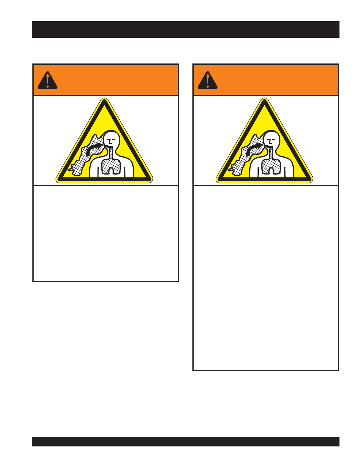
WARNING
SILICOSIS WARNING RESPIRATORY HAZARDS
Grinding/cutting/drilling of masonry, concrete, metal and
other materials with silica in their composition may give
off dust or mists containing crystalline silica. Silica is a
basic component of sand, quartz, brick clay, granite and
numerous other minerals and rocks. Repeated and/or
substantial inhalation of airborne crystalline silica can
cause serious or fatal respiratory diseases, including
silicosis. In addition, California and some other
authorities have listed respirable crystalline silica as a
substance known to cause cancer. When cutting such
materials, always follow the respiratory precautions
mentioned above.
WARNING
Grinding/cutting/drilling of masonry, concrete, metal and
other materials can generate dust, mists and fumes
containing chemicals known to cause serious or fatal
injury or illness, such as respiratory disease, cancer,
birth defects or other reproductive harm. If you are
unfamiliar with the risks associated with the particular
process and/or material being cut or the composition of
the tool being used, review the material safety data
sheet and/or consult your employer, the material
manufacturer/supplier, governmental agencies such as
OSHA and NIOSH and other sources on hazardous
materials. California and some other authorities, for
instance, have published lists of substances known to
cause cancer, reproductive toxicity, or other harmful
effects.
Control dust, mist and fumes at the source where
possible. In this regard use good work practices and
follow the recommendations of the manufacturers or
suppliers, OSHA/NIOSH, and occupational and trade
associations. Water should be used for dust
suppression when wet cutting is feasible. When the
hazards from inhalation of dust, mists and fumes cannot
be eliminated, the operator and any bystanders should
always wear a respirator approved by NIOSH/MSHA for
the materials being used.
Page 4

TABLE OF CONTENTS
MQ WHITEMAN — HHN-31V
GASOLINE POWERED RIDE-
ON TROWEL
Proposition 65 Warning ............................................ 2
Silicosis/Respiratory Warnings ................................. 3
Table Of Contents .................................................... 4
Training Checklist ..................................................... 5
Daily Pre-Operation Checklist .................................. 6
Parts Ordering Procedures ...................................... 7
Rules For Safe Operation .....................................8-9
Operation And Safety Decals ................................. 10
Specifications ......................................................... 11
General Information ............................................... 12
Controls and Indicators ..................................... 13-14
New Machine Setup Instructions ........................... 15
Initial Start-Up ...................................................16-18
Maintenance ..................................................... 19-24
Troubleshooting ................................................25-26
Explanation Of Codes In Remarks Column ........... 27
Suggested Spare Parts .......................................... 28
Name Plate And Decals ....................................30-31
Pivot/Gear Box-Right-Side Assy. ....................... 32-33
Pivot/Gear Box-Left-Side Assy. .........................34-35
Gearbox Assy. ................................................... 36-37
Control Steering (Assist) Assy........................... 38-41
Twin Pitch Assy. (Left/Right) ..............................42-45
Drive Assy. ........................................................ 58-59
5-Blade Spider Assy. (Left) ............................... 60-61
5-Blade Spider Assy. (Right) .............................62-63
Stabilizer Ring Assy. ........................................... 64-65
Seat and Frame Assy. ........................................ 66-67
Frame and Components .................................... 68-69
Foot Pedals Assy. ............................................... 70-71
Throttle Foot Pedal Assy. ................................... 72-73
Battery Assy. ...................................................... 74-75
Spray Assy. ........................................................ 76-77
Front Panel Assy. ............................................... 78-79
Top Right Panel Assy.......................................... 80-81
E-Z Mover and Lift ............................................. 82-83
Wiring Diagram ....................................................... 84
Terms and Conditions Of Sale — Parts .................. 85
NOTE
Specifications and part
numbers are subject to
change without notice.
HHN 31V • RIDE-ON POWER TROWEL — OPERATION & PARTS MANUAL — REV. #5 (03/02/07) — PAGE 4
PAGE 4 — HTN 31V
Page 5
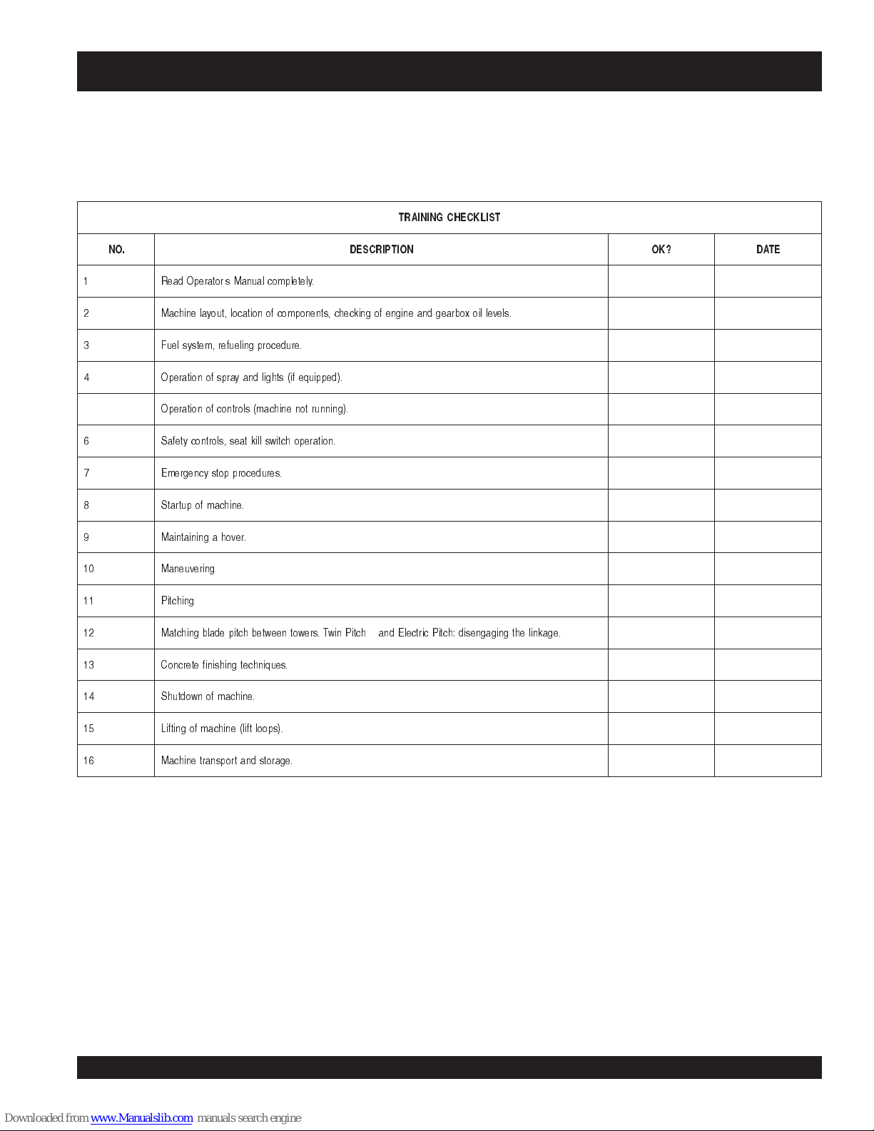
TRAINING CHECKLIST
TRAINING CHECKLIST
This checklist will lists some of the minimum requirements for machine maintenance and operation. Please feel free to detach it and
make copies. Use this checklist whenever a new operator is to be trained or it can be used as a review for more experienced
operator’s.
TSILKCEHCGNINIART
.ON NOITPIRCSED ?KO ETAD
! "#$
"$
% &'
( )
* '
+
,
-
.-)-&0&&
#1
! &'
2 "$3
%
Operator _________________________________________ Trainee __________________________________________
COMMENTS:
HHN 31V • RIDE-ON POWER TROWEL — OPERATION & PARTS MANUAL — REV. #5 (03/02/07) — PAGE 5
Page 6

DAILY PRE-OPERATION CHECKLIST
1 .levellioenignE
2 .levellioxobraeG
3 .leveltnaloocrotaidaR
4 .sedalbfonoitidnoC
5 .noitarepohctipedalB
6 .noitarepo)taes(hctiwslliK
7 .noitarepolortnocgnireetS
8 stlebfonoitidnoC
COMMENTS:
DAILY PRE-OPERATION CHECKLIST
TSILKCEHCNOITAREPO-ERPYLIAD
HHN 31V • RIDE-ON POWER TROWEL — OPERATION & PARTS MANUAL — REV. #5 (03/02/07) — PAGE 6
PAGE 6 — HTN 31V
Page 7

Effective: January 1st, 2006
Ordering parts has never been easier!
PARTS ORDERING PROCEDURES
Choose from three easy options:
Best Deal!
Order via Internet (Dealers Only):
Order parts on-line using Multiquip’s SmartEquip website!
■
View Parts Diagrams
■
Order Parts
■
Print Specification Information
Goto www.multiquip.com and click on
Order Parts
to log in and save!
Order via Fax (Dealers Only):
All customers are welcome to order parts via Fax.
Domestic (US) Customers dial:
1-800-6-PARTS-7 (800-672-7877)
Order via Phone:
Non-Dealer Customers:
Contact your local Multiquip Dealer for
parts or call 800-427-1244 for help in
locating a dealer near you.
If you have an MQ Account, to obtain a
Username and Password, E-mail us at:
parts@multiquip.com.
To obtain an MQ Account, contact your
District Sales Manager for more information.
internet
Use the
on
Standard orders
complete part numbers.*
Fax
your order in and qualify for a 2% Discount
on
Standard orders
complete part numbers.*
Domestic (US) Dealers Call:
1-800-427-1244
and qualify for a 5% Discount
for all orders which include
for all orders which include
International Customers
their local Multiquip Representatives for
Parts Ordering information.
Note: Discounts Are Subject To Change
Note: Discounts Are Subject To Change
should contact
When ordering parts, please supply:
❒❒
❒
Dealer Account Number
❒❒
❒❒
❒
Dealer Name and Address
❒❒
❒❒
❒
Shipping Address (if different than billing address)
❒❒
❒❒
❒
Return Fax Number
❒❒
❒❒
❒
Applicable Model Number
❒❒
❒❒
❒
Quantity, Part Number and Description of Each Part
❒❒
NOTE
www.multiquip.com
All orders are treated as
and will ship the same day if received prior
to 3PM PST.
WE ACCEPT ALL MAJOR CREDIT CARDS!
HHN 31V • RIDE-ON POWER TROWEL — OPERATION & PARTS MANUAL — REV. #5 (03/02/07) — PAGE 7
❒❒
❒
Specify Preferred Method of Shipment:
❒❒
✓
UPS/Fed Ex
■
■
■ Next Day
■
Standard Orders
Priority One
Ground
Second/Third Day
✓ DHL
✓
Tr u c k
Page 8
HHN-31V— RULES FOR SAFE OPERATION
■
CAUTION:
Failure to follow instructions in this manual may
lead to serious injury or even death! This
equipment is to be operated by trained and
qualified personnel only! This equipment is for
industrial use only.
The following safety guidelines should always be used when
operating the trowel.
GENERAL SAFETY
■
DO NOT operate or service this equipment
before reading this entire manual.
■
This equipment should not be operated by persons under
18 years of age.
■
NEVER operate this equipment without
proper protective clothing, shatterproof
glasses, steel-toed boots and other
protective devices required by the job.
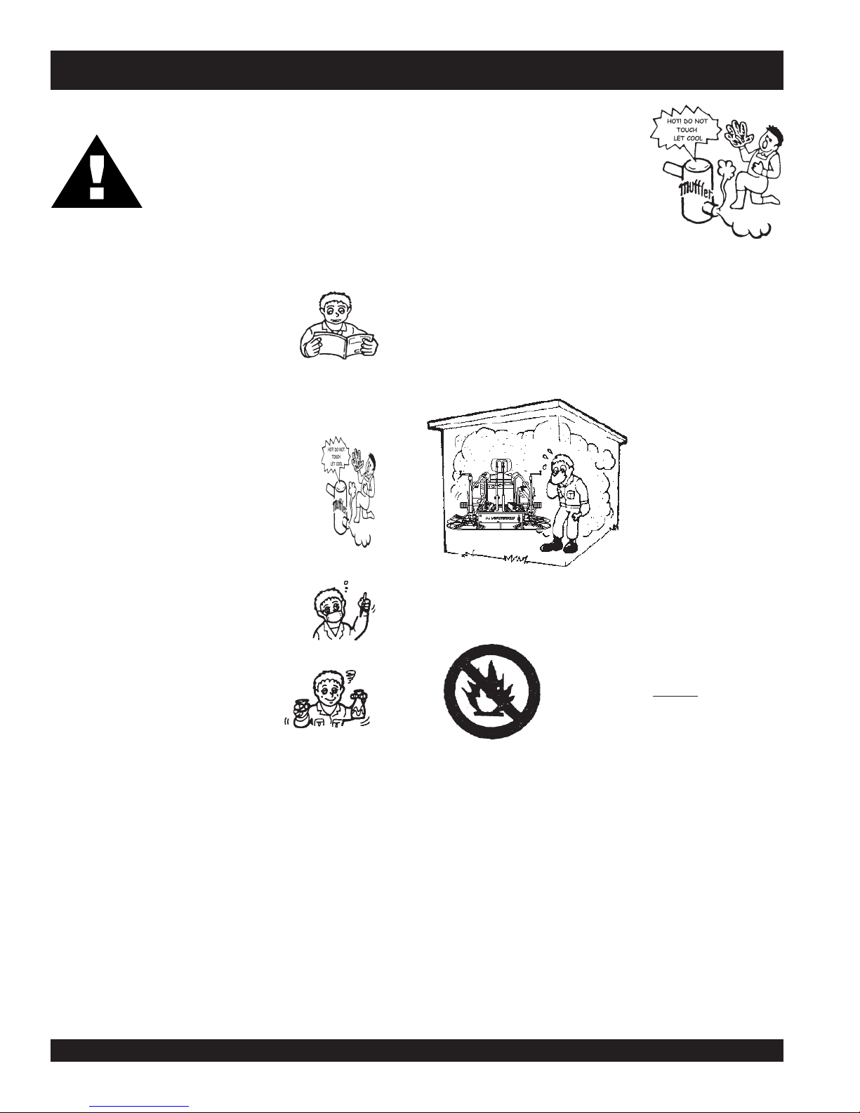
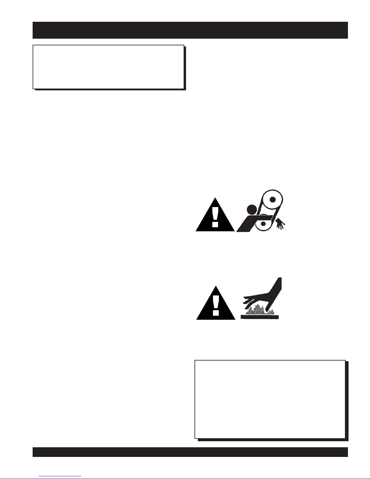
NEVER touch the hot exhaust
manifold, muffler or cylinder. Allow
these parts to cool before servicing
engine or trowel.
■
High Temperatures – Allow the engine to cool before adding
fuel or performing service and maintenance functions. Contact
hot
with
■
The ride-on trowel engine requires an adequate free flow of
cooling air. Never operate the ride-on trowel in any enclosed
or narrow area where free flow of the air is restricted. If the air
components can cause serious burns.
flow is restricted it will
cause serious damage to
the trowel or engine and
may cause injury to
people. Remember the
trowel's engine gives off
DEADLY carbon monoxide
gas.
■
NEVER operate this equipment when not
feeling well due to fatigue, illness or
taking medicine.
■
NEVER operate this equipment under
the influence or drugs or alcohol.
■
NEVER use accessories or attachments, which are not
recommended by Multiquip for this equipment. Damage to
the equipment and/or injury to user may result.
■
Manufacturer does not assume responsibility for any accident
due to equipment modifications.
■
Whenever necessary, replace nameplate, operation and
safety decals when they become difficult read.
■
Always check the machine for loosened threads or bolts
before starting.
■
■
■
Always refuel in a well-ventilated area, away from sparks
and open flames.
n Always use extreme caution when
working with flammable liquids. When
refueling, stop the engine and allow it
to cool. DO NOT
the trowel. Fire or explosion could result
from fuel vapors, or if fuel is spilled on a
hot engine.
NEVER operate the trowel in an explosive atmosphere or
near combustible materials. An explosion or fire could result
causing severe
Topping-off to filler port is dangerous, as it tends to spill fuel.
bodily harm or even death.
smoke around or near
HHN 31V • RIDE-ON POWER TROWEL — OPERATION & PARTS MANUAL — REV. #5 (03/02/07) — PAGE 8
PAGE 8 — HTN 31V
Page 9

HHN-31V— RULES FOR SAFE OPERATION
The following safety guidelines should always be used when
operating the HHN Ride-on Power Trowel:
GENERAL SAFETY
■
DO NOT operate this equipment unless all guards and safety
devices are attached and in place.
■
Always use proper heavy lifting techniques when moving
equipment. This ride-on trowel is very heavy. It should be
lifted only with a lifting device (i.e. crane, forklift, etc.) with a
lifting capacity of at least one ton.
■
Always check to make sure that the operating area is clear
before starting the engine.
■
Always test the safety kill switch before operating the
equipment.
■
NEVER place your feet inside the guard rings while starting
or operating this equipment.
■
Always keep clear of rotating or moving parts while operating
this equipment.
■
NEVER leave the machine unattended while running.
■
Always refuel in a well-ventilated area, away from sparks
and open flames.
MAINTENANCE SAFETY
■
Disconnect the battery and spark plug wires before attempting
any type of service.
■
Securely support any machine components that must be
raised.
■
NEVER lubricate components or attempt service on a running
machine.
■
Always allow the machine a proper amount of time to cool
before servicing.
■
Keep the machinery in proper running condition.
■
Make sure that there is no buildup of concrete, grease, oil or
debris on the machine.
■
Fix damage to the machine immediately and always replace
broken parts.
■
Dispose of hazardous waste properly. Examples of potentially
hazardous waste are used motor oil, fuel and fuel filters.
■
DO NOT use food or plastic containers to dispose of
hazardous waste.
■
DO NOT pour waste, oil or fuel directly onto the ground,
down a drain or into any water source.
■
Moving Parts - Shut down the engine and disconnect battery
before performing service or maintenance functions. Contact
with moving parts can cause serious injury.
Moving the Ride-On Trowel
CAUTION:
CAUTION:
Temperatures
■
High Temperatures – Allow the machine
and engine to cool before adding fuel or
performing service and maintenance functions.
hot
Contact with
serious burns.
CAUTION:
Emergencies
■
extinguisher
location of the nearest telephone. Also know
the phone numbers of the nearest
doctor
will be invaluable in the case of an emergency.
Always know the location of the nearest
and
components can cause
and
first aid kit
fire department
. Know the
ambulance
. This information
The HHN series Ride-on Power Trowel is designed to be moved
and handled several ways.
The easiest way to lift the ride-on trowel is to utilize the lift loops
that are welded to the frame. These lift loops are located to the
left and right sides of the operator’s seat (Figure 3, Page 11).
fire
A strap or chain can be attached to these lift loops, allowing a
forklift or crane to lift the ride-on trowel up onto a slab of concrete.
The strap or chain should have a minimum 2,000 pounds (1000-
,
kg) lifting capacity and the lifting gear must be capable of lifting
at least this amount.
This ride-on trowel is very
awkward to move around. Use proper heavy
lifting procedures and DO NOT attempt to lift
the ride-on trowel by the guard rings.
heavy
and
HHN 31V • RIDE-ON POWER TROWEL — OPERATION & PARTS MANUAL — REV. #5 (03/02/07) — PAGE 9
Page 10

HHN-31V— OPERATION AND SAFETY DECALS
Machine Safety Decals
The HHN series Ride-on Power Trowel is equipped with a number of safety decals. These decals are provided for operator safety
and maintenance information. Table 1 below illustrates these decals as they appear on the machine. Should any of these decals
become unreadable, replacements can be obtained from your dealer.
HHN 31V • RIDE-ON POWER TROWEL — OPERATION & PARTS MANUAL — REV. #5 (03/02/07) — PAGE 10
PAGE 10 — HTN 31V
Page 11

HHN -31V — SPECIFICATIONS
Figure 1. HHN Dimension Specifications
snoitacificepSNNH.2elbaT s
RETEMARAPNOITACIFICEPS )DRAUGNAV(V13-NNH
)mc(.ni–htgneL–A )4.642(0.79
)mc(.ni–htdiW–B )721(0.05
1
)mc(.ni–thgieH–C
gnitarepO).sgk(.sbl–thgieW )774(240,1
gnippihS).sgk(.sbl–thgieW )555(422,1
2
ABd–erusserPdnuoS
2
s/tf–noitarbiV
3
s/m(2)
.P.H–enignE 13
)sretil(snollag–knaTleuF )91(5
MPR–rotoR 061ot06
)mc(.ni–htdiWhtaP )132(19
liOnoitacirbuL PE5RG022OSI
yticapaCliOxoBraeG .ZO441
)daoLlluF(noitpmusnoCleuF RH-PHB/BL45.0
yticapaCrotaidaR .LAG0.1
NOTE:
1. This value does not include seat height. To obtain total
height (seat ) add 4 inches (10.2 cm.).
2. Sound pressure is "A" weighted . Measured at the operators
ear position while the ride-on trowel is operating at full
throttle on concrete in a manner most often experienced in
normal
“
” circumstances. Sound pressure may vary
depending upon the condition of the concrete. Hearing
3. The vibration level indicated is the maximum RMS (Root
Mean Square) value obtained at the handle grip while
operating the ride-on trowel on curing concrete in a
manner most often experienced in “
circumstances. Values were obtained from all three axes
of motion. The values shown represent the maximum RMS
value from these measurements.
protection is always recommended.
)711(0.64
59
)5.2(0.8<
normal
”
HHN 31V • RIDE-ON POWER TROWEL — OPERATION & PARTS MANUAL — REV. #5 (03/02/07) — PAGE 11
Page 12

HHN -31V — GENERAL INFORMATION
HHN RIDE-ON TROWEL FAMILIARIZATION
The HHN series Ride-On Power Trowel is designed for the
floating and finishing of concrete slabs.
Take a walk around the HHN Ride-On Power Trowel. Take notice
of all the major components (see Figures 2 and 3, pages 13 and
14) like the engine, blades, air cleaner, fuel system, fuel shut-off
valve, ignition switch etc. Check that there is always oil in the
engine, and gear oil in the gear box assembly.
Read all the safety instructions carefully. Safety instructions will
be found throughout this manual and on the machine. Keep all
safety information in good, readable condition. Operators should
be well trained on the operation and maintenance of the HHN
Ride-On Power Trowels.
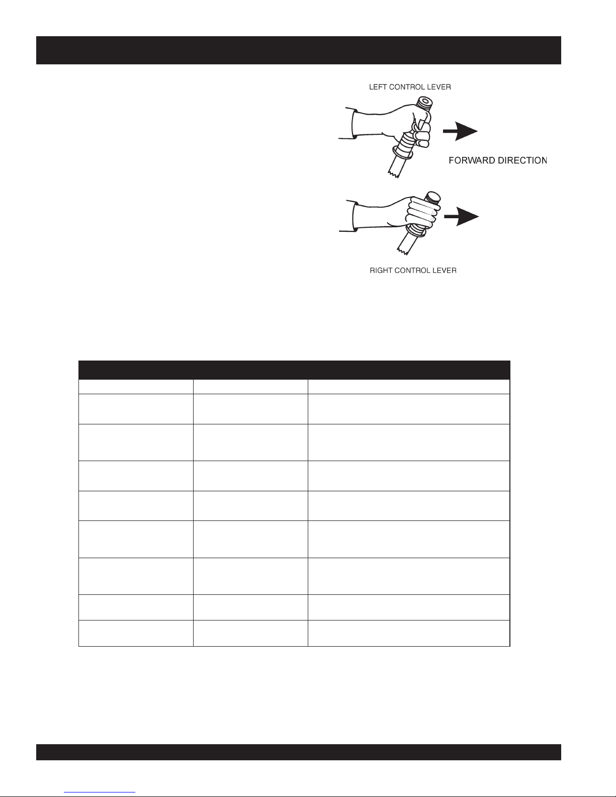
Look at the operator control levers. Grab the control levers and
move them around a bit. Look to see how moving the control
levers causes the gearboxes and frame to move.
Notice the foot pedal which controls the engine speed. Also take
a look at the main driveline of the trowel. Take note and reference
how the belts look, this is the way the belts should look when
adjusted properly.
Before using your HHN Ride-On Power Trowel, test it on a flat
watered down section of finished concrete. This trial test run will
increase your confidence in using the trowel and at the same
time it will familiarize you with the trowel’s controls and indicators.
In addition you will understand how the trowel will handle under
actual conditions.
Engine
Gearboxes
The HHN Ride on Power Trowel consist of two separate gearbox
assemblies that are enclosed in rugged cast aluminum gear
cases.
The gearbox casing holds 50% more oil capacity than
competitors, which allows more lubrication to be provided to
critical points.
Steering Assist
Dual control levers located in front of the operator's seat are
provided for steering the HHN Ride on Power Trowel. The control
levers are linked to two spring loaded cylinders.
Push the left control lever forward and pull the right control lever
backward and the trowel will rotate clockwise on approximately
a center axis. Pull the left control lever backward and push the
right control lever forward and the trowel will rotate
counterclockwise. See Table 3 on page 15 for a complete
description on the control levers directional positioning.
Constant Velocity Joints (CV-Joints)
Constant velocity joints insure the efficient transfer of power to
the drive shaft and maintain the timing of the gearboxes without
any chance of slippage.
Training
For training, please use the “TRAINING CHECKLIST” located
in the front of this manual (Page 5). This checklist is not intended
to be a substitute for proper training but will provide an outline
for an experienced operator to provide training to a new operator.
The HHN Ride-On Power Trowel is equipped with a liquid cooled
31 HP Vanguard gasoline engine. Refer to the engine owner’s
manual for specific instructions regarding engine operation. This
manual is included with the ride-on trowel at the time of shipping
from Whiteman. Please contact your nearest Multiquip Dealer
for a replacement should the original manual disappear.
Blades
The blades of the ride-on power trowel finish the concrete as
they are swirled around the surface. Blades are classified as
combination (10 or 8 inches wide) and finish (6 inches wide).
The HHN ride-on power trowels are equipped with five blades
per rotor equally spaced in a radial pattern and attached to a
vertical rotating shaft by means of a
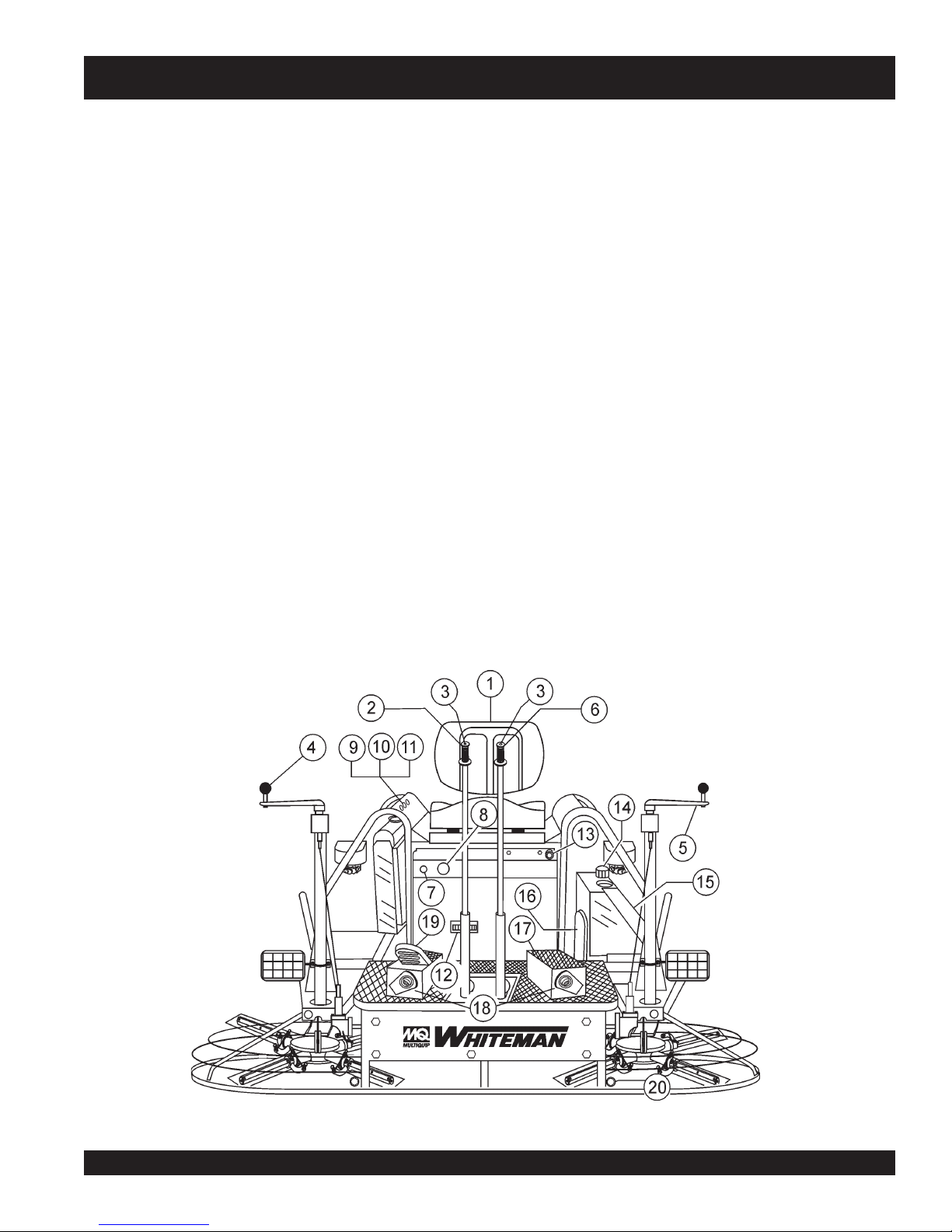
Figures 2 and 3 show the location of the controls, indicators and
general maintenance parts. Each control may perform more than
one function. The functions of each control or indicator is on
pages 13 and 14.
HHN 31V • RIDE-ON POWER TROWEL — OPERATION & PARTS MANUAL — REV. #5 (03/02/07) — PAGE 12
spider assembly.
PAGE 12 — HTN 31V
Page 13
HHN -31V — CONTROLS AND INDICATORS
1. Seat – Place for operator to sit. Engine will not start unless
operator is seated. Seat is adjustable, fore and aft for
operator comfort.
2. Steering Control Lever (right side) -Allows the unit to
move in either a forward, reverse left or right direction.
3. Retardant Spray Control Buttons – When pressed
allows retardant spray to flow through the spray nozzle
located at the front of the machine.
4. Twin Pitch Control – Adjusts the blade pitch for right side
of the trowel. Turn the crank as marked on its top surface to
increase or decrease blade pitch.
5. Twin Pitch Control – Adjusts the blade pitch for left side
of the trowel. Turn the crank as marked on its top surface to
increase or decrease blade pitch.
6. Steering Control Lever (left side) -Allows the unit to move
in either a forward, reverse left or right direction.
7. Light Switch – When activated, turns on four halogen
lights. Lights offer better visibility when working indoors.
8. Ignition Switch – With key inserted turn clockwise to
start engine.
9. Oil Indicator Light - Lights red when oil pressure is low.
10. Water Indicator Light - Lights red when water temperature
is high.
11. Charge Indicator - Lights red when electrical system is
not charging properly.
12. Hour Meter - Indicates number of hours the key switch is
in the "ON" position.
13. Choke Control Lever. - In cold weather pull this lever
forward about half way to start engine. After engine warms
push knob all the way in.
14. Fuel Gauge/Filler Cap - Indicates the amount of fuel in
the fuel tank. Remove this cap to add fuel.
15. Fuel Tank - Holds 5 gallons of unleaded gasoline.
16. Spare Belt Carrier - Contains a spare belt. Belt is used on
the drive pulley.
17. Left Foot Riser – Operator foot rest pedal.
18. Spray Nozzles – Spray nozzle for retardant.
19. Right Foot Pedal – Controls blade speed. Slow blade
speed is accomplished by slightly depressing the foot pedal.
Maximum blade speed is accomplished by fully depressing
the foot pedal.
20. EZ- Mover Boss – Front -side insertion point for EZ Mover.
Used when the transporting of the trowel is required.
HHN 31V • RIDE-ON POWER TROWEL — OPERATION & PARTS MANUAL — REV. #5 (03/02/07) — PAGE 13
Figure 2. HHN Controls and Indicators (Front)
Page 14
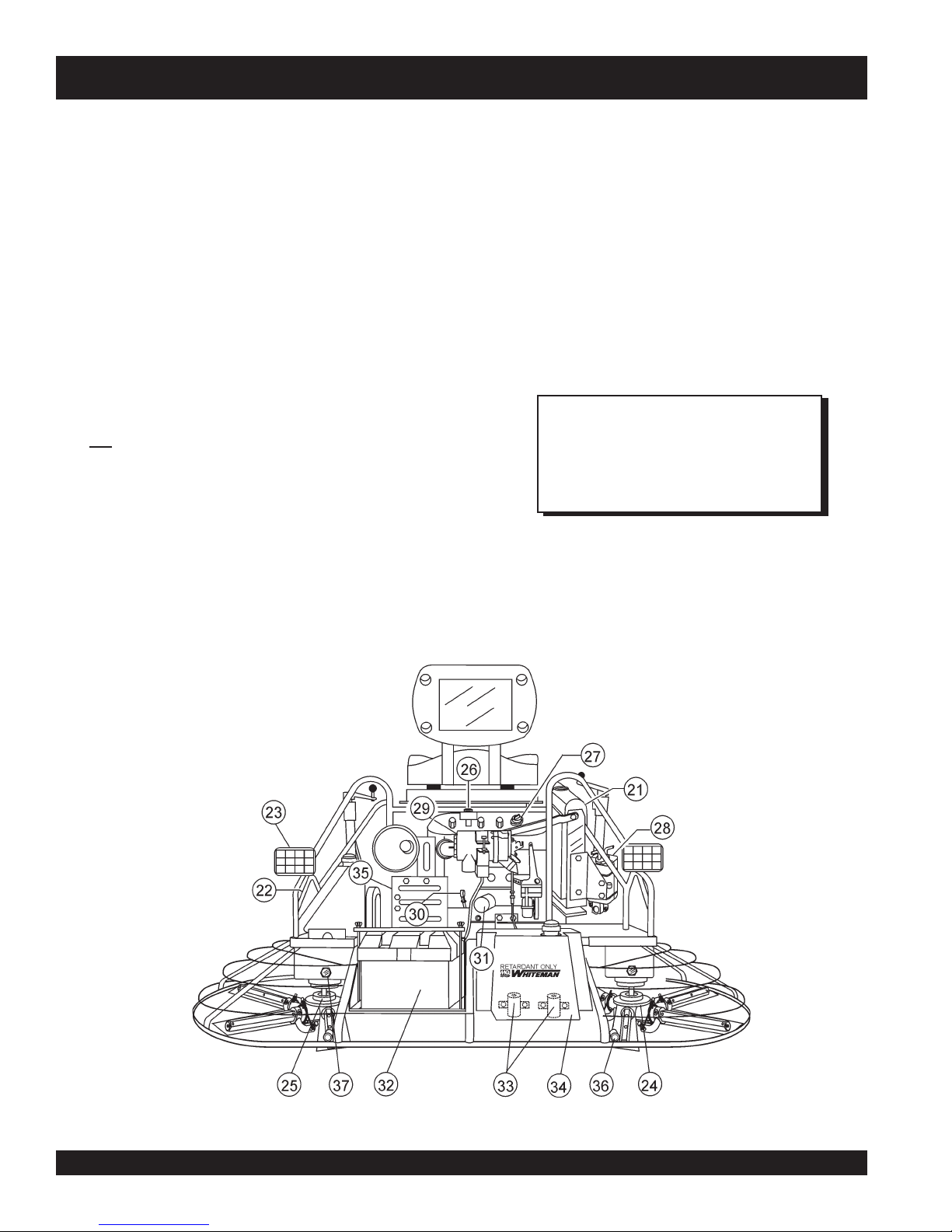
HHN -31V — CONTROLS AND INDICATORS
21. Radiator/Filler Cap – Holds coolant or water necessary to
keep engine at a safe operating temperature. Remove this
cap to add water or antifreeze. DO NOT revove this cap
when the engine is warm.
22. Lift Loops – Located on both the left and right sides of the
main frame. Used when the trowel must be lifted onto a
concrete slab.
23. Lights – Four 12 volt halogen lights are provided with this
unit.
24. Right-Side Spider – Consists (basic) of trowel arms,
blades, wear plate, and thrust collar etc.
25. Left-Side Spider – Consists (basic) of trowel arms, blades,
wear plate, and thrust collar etc.
26. Safety Kill Switch – Shuts down engine when operator is
not sitting in seat.
27. Engine Oil Filler Cap - Remove this cap to add engine oil.
28. Overflow Bottle - Supplies coolant to the radiator when
radiator coolant level is low. Fill to indicated level as shown
on bottle.
29. Engine Air Filter – Prevents dirt and other debris from
entering the fuel system. Lift locking latch on air filter
cannister to gain access to filter element.
30. Engine Dip Stick – Indicates engine oil level. Add oil as
required.
31. Oil Filter – Provides oil filtering for the engine.
32. Battery – Provides +12V DC power to the electrical system
33. Retardant Spray Motors – Used in conjunction with the
34. Retardant Spray Tank – Holds 5 gallons of retardant.
35. Belt Guard – Encloses drive belt used in conjunction with
36. EZ- Mover Boss – Back- side insertion point for EZ Mover.
37. Oil Sight Glass - Indicates the level of the hydraulic oil in
The following section is intended as a basic guide to the rideon trowel operation, and is not to be considered a complete
guide to concrete finishing. It is strongly suggested that all
operators (experienced and novice) read “
published by the American Concrete Institute, Detroit Michigan.
left and right spray control buttons.
clutch.
Used when the transporting of the trowel is required.
the gear box.
NOTE
Read this entire instruction manual
completely before attempting to
operate trowel.
Slabs on Grade
”
Figure 3. HHN Controls and Indicators (Rear)
HHN 31V • RIDE-ON POWER TROWEL — OPERATION & PARTS MANUAL — REV. #5 (03/02/07) — PAGE 14
PAGE 14 — HTN 31V
Page 15

HHN -31V — NEW MACHINE SETUP INSTRUCTIONS
Trowel Pre-Set-Up Instructions
The purpose of this section is to assist the user in setting up a
NEW
trowel. If your trowel is already assembled (seats, handles,
knobs and battery, then this section can be skipped.
NOTE
The new ride-on trowel cannot be put into service
until the pre-setup installation instructions are
completed. These pre-setup instructions only need
to be performed at the time of unpacking a
trowel.
Before packaging and shipping this Whiteman Ride-On Power
Trowel was run and tested at the factory. If there are problems,
please let us know.
Control Handle Assembly
The steering control handles are not attached to the trowel's two
lower handles at the time of shipment. To attach the steering
control handles to the two lower handle assemblies perform the
following:
1. Remove the bolts from the plastic bag tied to the control
towers.
2. Remove all protective wrapping and straps from the control
handles.
3. Slip the top (loose) piece into the base of the corresponding
handle, making sure to line up the holes.
4. Install the bolt through the lined up holes and tighten the
acorn nut onto the threaded end.
NEW
Seat Assembly
The seat is not installed on the trowel for shipping purposes.
To attach the seat perform the following:
There are two types of seats, depending on what type
of trowel you have. J and B series trowels have slots
on the seat mounting plate that allow fore and aft
adjustment of the seat. H-series trowels have a seat
that is mounted on tracks, similar to an automobile
seat. This seat can be adjusted fore and aft via the
control lever under the front of the seat.
1. Remove the seat from the protective wrapping.
2. Remove the bolts on the bottom of the seat, and place seat
on the seat mounting plate, then insert the bolts through
the holes or slots on the seat mounting plate and tighten.
Battery Setup
This trowel was shipped with a wet charged battery. This battery
may need to be charged for a brief period of time as per the
manufacturer instructions.
CAUTION:
NOTE
Use all safety precautions specified by the
battery manufacturer when working with the
battery.
NOTE
Some models are equipped with
adjustable height handles. Adjust the
height by placing the bolt through the
set of holes that corresponds to the
most comfortable height.
5. Pay close attention to any wires that may be inside the
control handles. DO NOT pinch or cut any wires during
installation.
6. Inside the plastic bag of parts are two knobs for the pitch
control tower cranks. Install these two knobs onto the tower
crank levers.
HHN 31V • RIDE-ON POWER TROWEL — OPERATION & PARTS MANUAL — REV. #5 (03/02/07) — PAGE 15
To install the battery on the trowel, make sure that the battery is
well seated in the battery box and the terminals are properly
connected. Close the plastic battery box cover and secure the
battery box.
Page 16
HHN -31V — INITIAL START-UP
This section is intended to assist the operator with the initial
start-up of the HHN series Ride-On Power trowel. It is extremely
important that this section be read carefully before attempting to
use the trowel in the field.
DO NOT use your ride-on power trowel until this section is
thoroughly understood.
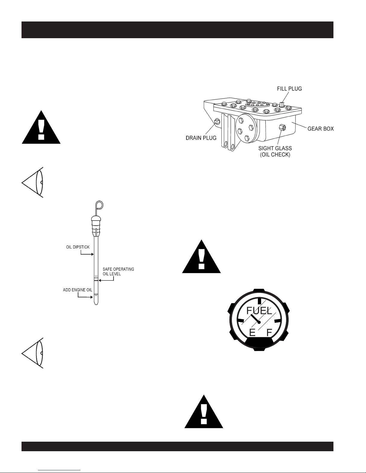
2. The oil level of the gear box should be at the half-way point
of the sight glass (Figure 5). The gear box oil capacity is
144 oz. If additional oil is required, unscrew the oil fill plug
located on top of the gearbox, and refill with ISO 220 A
GMA GR 5 EP oil.
CAUTION:
Failure to understand the operation of the HHN
Ride-ON Power Trowel could result in severe
damage to the trowels or personal injury.
See Figures 2 and 3 (Pages 13 and 14) for
the location of any control or indicator
referenced in this manual.
Engine Oil Level
1. Pull the engine oil dipstick from its holder.
2. Determine if engine oil is low (Figure 4), add
correct amount of engine oil to bring oil level
to a normal safe level.
Figure 5. Gearbox Oil Plugs/Sight Glass
Fuel
1. Determine if the engine fuel is low (Figure 6). If fuel level is
low, remove the fuel filler cap and fill with unleaded gasoline.
Figure 4. Engine Oil Dipstick
Gearbox Oil Level
1. Check the gearbox oil level in both gearboxes
by viewing the sight glass at the rear of the
gearbox. See Figure 5.
CAUTION:
Handle fuel safely. Motor fuels are highly
flammable and can be dangerous if
mishandled. DO NOT smoke while
refueling. DO NOT attempt to refuel the ride-
on trowel if the engine is hot or running.
Figure 6. Fuel Gauge
CAUTION:
Never store the ride-on trowel with fuel in the
tank for any extended period of time. Always
clean up spilled fuel immediately.
HHN 31V • RIDE-ON POWER TROWEL — OPERATION & PARTS MANUAL — REV. #5 (03/02/07) — PAGE 16
PAGE 16 — HTN 31V
Page 17

HHN 31V-TC — INITIAL START-UP
Starting the Engine
1. With one foot on the ground and the other foot placed on
the trowel's platform, grab hold of any part of the frame and
lift yourself onto the trowel. Then sit down in the operator's
seat.
2. The Whiteman Ride-On Power trowel is equipped with a
kill switch
safety
assembly. Remember the engine will not start unless an
operator is sitting in the operator’s seat. The weight of an
operator depresses an electrical switch, which will allow
the engine to start.
. This switch is located beneath the seat
CAUTION:
NEVER disable or disconnect the kill switch. It
is provided for the operator's safety and injury
may result if it is disabled, disconnected or
improperly maintained.
3. It is recommended that the kill switch be used to stop the
engine after every use. Doing this will verify that the switch
is working properly and presents no danger to the operator.
Remember to turn the key to the “OFF” position after
stopping the machine. Not doing so may drain your units’
battery.
4. The right foot pedal (Figure 7) controls blade and engine
speed. The position of the foot pedal determines the blade
speed. Slow blade speed is obtained by slightly depressing
the pedal. Maximum blade speed is obtained by fully
depressing the pedal.
7. Turn the ignition key clockwise to the (start) position. The
oil
Figure 8. Oil and Charge Indicator Lights
8. Turn ignition key fully clockwise and listen for engine to
start. Once engine has started release ignition key.
9. If the engine fails to start in this manner, consult the engine
owner's manual supplied with the trowel.
10. Test the safety kill switch by standing up briefly. The switch
under the seat should cause the engine to stop. If the kill
switch fails to shut down the engine. Turn off the engine
with the key switch and fix the safety kill switch. See Table
4 (Troubleshooting ) for possible problems.
11. Repeat this section a few times to get fully acquainted with
the engine starting procedure.
Steering
Two control levers located in front of the operator’s seat provide
directional control for the HHN Ride-On Power Trowel. Table 3
(Page 18) illustrates the various directional positions of the
joysticks and their effect on the ride-on trowel.
and charge indicator lights (Figure 8) should be on.
Figure 7. Blade Speed Control Foot Pedal
5. Keep your foot OFF the gas pedal (right foot pedal). If the
engine is cold, adjust the choke but in all circumstances,
start the engine at idle (without touching the gas pedal).
6. Insert the
HHN 31V • RIDE-ON POWER TROWEL — OPERATION & PARTS MANUAL — REV. #5 (03/02/07) — PAGE 17
ignition key
into the ignition switch .
NOTE
All directional references with respect
to the steering control levers are from
operator’s
the
2. Push both the left and right control levers forward. See
Figure 9.
3. With your right foot quickly depress the right foot pedal
halfway. Notice that the ride-on power trowel begins to move
in a forward direction. Return both joystick controls to their
neutral position to stop forward movement, then remove
your right foot from the right foot pedal.
seat position.
Page 18
4. Practice holding the machine in one place as you increase
blade speed. When about 75% of maximum blade speed
has been reached, the blade will be moving at proper
finishing speed. The machine may be difficult to keep in
one place. Trying to keep the ride-on trowel stationary is a
good practice for operation.
5. Practice maneuvering the ride-on trowel using the
information listed in Table 3. Try to practice controlled
motions as if you were finishing a slab of concrete. Practice
edging and covering a large area.
6. Try adjusting the pitch of the blades. This can be done with
the ride-on trowel stopped or while the trowel is moving,
whatever feels comfortable. Test the operation of optional
equipment like retardant spray and lights if equipped.
7. Push both the left and right joysticks backward and repeat
steps 3 through 6 while substituting the word reverse for
Figure 9. Left and Right Control Levers
forward.
HHN -31V — INITIAL START-UP
REVELLORTNOC NOITCERID STLUSER
tfeL
tfeL
thgiR
thgiR
thgiRdnatfeL
thgiRdnatfeL
thgiRdnatfeL
thgiRdnatfeL
reveLlortnoCevoM
drawroF
reveLlortnoCevoM
drawkcaB
reveLlortnoCevoM
drawroF
reveLlortnoCevoM
drawkcaB
htoBevoM
drawroFsreveLlortnoC
htoBevoM
drawkcaBsreveLlortnoC
htoBevoM
thgiRehtotsreveLlortnoC
htoBevoM
tfeLehtotsreveLlortnoC
gninoitisoPlanoitceriDreveLlortnoC.3elbaT
otlewortno-edirehtsesuaC
.thgirehtotdnadrawrofevom
otlewortno-edirehtsesuaC
.tfelehtotdnadrawkcabevom
otlewortno-edirehtsesuaC
.tfelehtotdnadrawrofevom
otlewortno-edirehtsesuaC
.thgirehtotdnadrawkcabevom
lewortno-edirehtsesuaC
nidrawrofevomot
.enilthgiartsa
lewortno-edirehtsesuaC
drawkcabevomot
.enilthgiartsani
lewortno-edirehtsesuaC
.thgirehtotevomot
lewortno-edirehtsesuaC
tfelehtotevomot
HHN 31V • RIDE-ON POWER TROWEL — OPERATION & PARTS MANUAL — REV. #5 (03/02/07) — PAGE 18
PAGE 18 — HTN 31V
Page 19
MAINTENANCE PROCEDURES
.
See the engine manual supplied with your machine for
appropriate engine maintenance schedule and
troubleshooting guide for problems.
At the front of the book (Page B) there is a “Daily Pre-Operation
Checklist”. Make copies of this checklist and use it on a daily
basis.
Disconnect spark plug wires and battery cables before
attempting any service or maintenance on the ride-on trowel.
MAINTENANCE SCHEDULE
Daily (8-10 Hours)
NOTE
Checking The Drive Belt
The drive belt needs to be changed as soon as it begins to show
signs of wear. DO NOT reuse a belt under any circumstances.
Indications of excessive belt wear are fraying, squealing when
in use, belts that emit smoke or a burning rubber smell when in
use.
Under normal operating conditions, a drive belt may last
approximately 150 hours. If your trowel is not reaching this kind
of life span for drive belt wear, check the drive belt for proper
pulley alignment and spacing .
To gain access to the drive belt, remove the drive belt guard
cover, then visually inspect the drive belt for signs of damage or
excessive wear. If thedrive belt is worn or damaged, replace the
drive belt.
HHN -31V — MAINTENANCE
1. Check the fluid levels in the engine and gearboxes, fill as
necessary.
Weekly (30-40 Hours)
1. Relube arms, thrust collar and steering links.
2. Replace blades if necessary.
3. Check and clean or replace the engine air filter as
necessary.
4. Replace engine oil and filter as necessary, see engine
manual.
Monthly (100-125 Hours)
1. Remove, clean, reinstall and relube the arms and thrust
collar. Adjust the blade arms.
2. Replace gearbox lubricant after the first 100 hours of
operation. Then replace every 500-600 hours.
3. Check drive belt fro excessive wear.
Yearly (500-600 Hours)
1. Check and replace if necessary the arm bushings, and
thrust collar bushings, shaft seals and belts.
2. Check pitch control cables for wear.
WARNING:
DO NOT attempt to insert hands or tools into the belt area while
the engine is running and the safety guard has been removed.
Keep fingers, hands, hair and clothing away from all moving
parts to prevent bodily injury.
WARNING:
DO NOT remove the V-belt guard cover until the muffler has
cooled. Allow the entire trowel to cool down before performing
this procedure.
3. Replace gearbox lubricant.
HHN 31V • RIDE-ON POWER TROWEL — OPERATION & PARTS MANUAL — REV. #5 (03/02/07) — PAGE 19
NOTE
zz
z
Leave the existing drive belt intact until instructed
zz
to cut it.
zz
z
Leave the engine in place for this procedure. It is
zz
not necessary to slide the engine to replace the
drive belt.
zz
z
Have a 3/4 X 1 X 3.25 inch wooden block available.
zz
Page 20
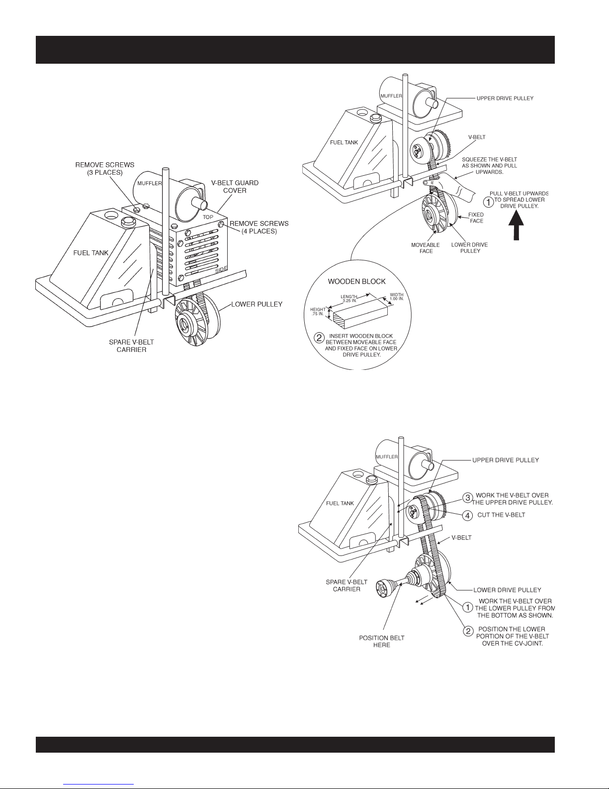
Removing the V-belt
1. Remove the seven HHC screws that secure the V-belt
guard cover as shown in Figure 10. Please note that the
screw under the muffler is some what difficult to remove.
2. Remove the drive belt guard cover from the trowel and set
aside.
.
HHN -31V — MAINTENANCE
Figure 11. Lower Drive Pulley
Figure 10. Drive Belt Guard Cover
3. Once the drive belt "Guard Cover" has been removed,
squeeze the drive belt as shown in Figure 11, and pull the
V-belt upwards. This will spread open the faces of the
drive pulley.
4.
Insert
the 3/4" X 1" X 3.25" block between the moveable
face and the fixed face of the lower drive pulley. This block
will help keep the lower drive pulley faces open while
installing the new V-belt.
5. Work the drive belt over the lower drive pulley as shown in
Figure 12, position it over the CV-joint boot, then pull the
belt over the upper drive pulley also shown in Figure 12.
6. Once drive belt is free from both the upper and lower pulley's
CUT
the drive belt.
lower
HHN 31V • RIDE-ON POWER TROWEL — OPERATION & PARTS MANUAL — REV. #5 (03/02/07) — PAGE 20
Figure 12. Drive Belt Removal
PAGE 20 — HTN 31V
Page 21
HHN -31V — MAINTENANCE
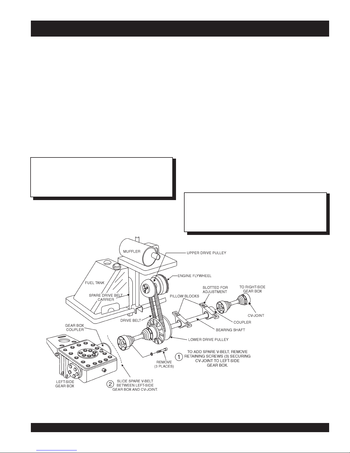
Installing the Replacement Drive Belt
The HHN trowel is equipped with a replacement drive belt (spare)
carrier (Figure 13), which is mounted on the back-side of the fuel
tank opposite the clutch. Make sure that there is ALWAYS a spare
drive belt in the drive belt carrier before the trowel is placed on a slab
to finish concrete.
1. To add a replacement drive belt for use on the upper and
lower drive pulleys, remove the 2 screws that secure the
spare drive belt carrier.
2. Remove the spare drive belt carrier from the trowel, and
free the replacement drive belt.
3. Slide the replacement drive belt over the upper and lower
pulleys reversing steps 1 thru 5 on page 20.
NOTE
It will be necessary to disconnect the CV-Joint from the
left-side gear box coupler. This means the removal of the
three screws that secure the CV-Joint to the gear box.
Spare Drive Belt Replacement
To replace a spare drive belt, be prepared to disconnect the CVjoint from the left-side gear box.
1. Place the HHN trowel on jack stands, and observe all safety
precautions.
2. Remove the three screws that secure the CV-joint to the
left-side gear box coupler.
3. Once the CV-joint has been separated from the left-side
gearbox, push the CV-joint inward so that a gap exist
between the gearbox and the CV-joint (Figure 13). Slide
the spare V-belt between the gear box coupler and the CVjoint. If any grease or oil is present on the replacement
drive belt, remove it.
4. Place the spare drive belt inside the drive belt carrier, and
secure the spare belt carrier to the back-side of fuel tank.
5. Install the three screws that secure the CV-joint to the leftside gear box coupler.
It may be necessary to disconnect the CV-Joint from the
lower pulley coupler. This means the removal of the three
screws that secure the CV-Joint to the pulley.
NOTE
Figure 13. Spare V-Belt Replacement
HHN 31V • RIDE-ON POWER TROWEL — OPERATION & PARTS MANUAL — REV. #5 (03/02/07) — PAGE 21
Page 22
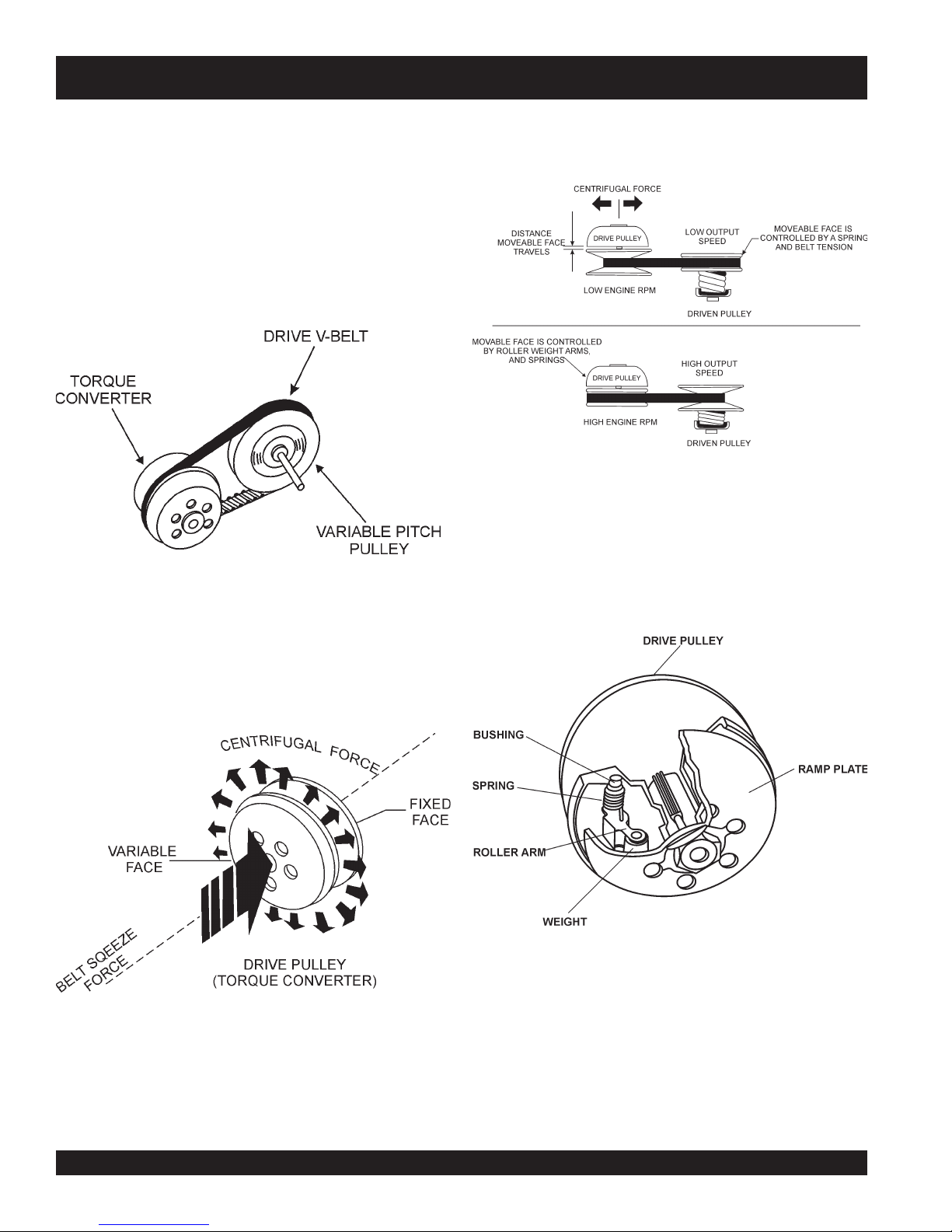
HHN -31V — MAINTENANCE
The HHN trowel is equipped with a "Torque Converter" which
supplies torque to both the left and right gear boxes.
The function of the a torque converter is to automatically deliver the
correct amount of torque required by the trowel under all load
conditions. This enables the trowel to deliver the necessary torque
for float pan applications and the high rotor speeds required for
burnishing concrete.
The torque converter used in the HHN series trowels is of the
variable pitch pulley type (Figure 14) connected by a drive belt.
Fig. 14. Torque Converter/Variable Pitch Pulley
As shown in Figure 16, centrifugal force pushes the roller arms (see
Figure 17 below) against the ramp plate, forcing moveable face
toward fixed face squeezing belt.
The "Variable Pitch Pulleys" have one
. The
face
is controlled by roller weight arms and springs, which change
position according to engine speed. The
is controlled by a spring and belt tension.
face
Fig. 16. Pulley Interaction
fixed face
drive
pulley ( torque converter, Figure 17) moveable face
, and one
driven
pulley
moveable
moveable
Drive Pulley
The "Drive Pulley" uses centrifugal force (Figures 15 and 16)
to create a belt squeeze force transmitted at the pulley faces.
This condition functions as an automatic clutch.
Figure 15. Torque Converter (Centrifugal Force)
Fig. 17. Variable Pitch Pulley
HHN 31V • RIDE-ON POWER TROWEL — OPERATION & PARTS MANUAL — REV. #5 (03/02/07) — PAGE 22
PAGE 22 — HTN 31V
Page 23
HHN -31V — MAINTENANCE
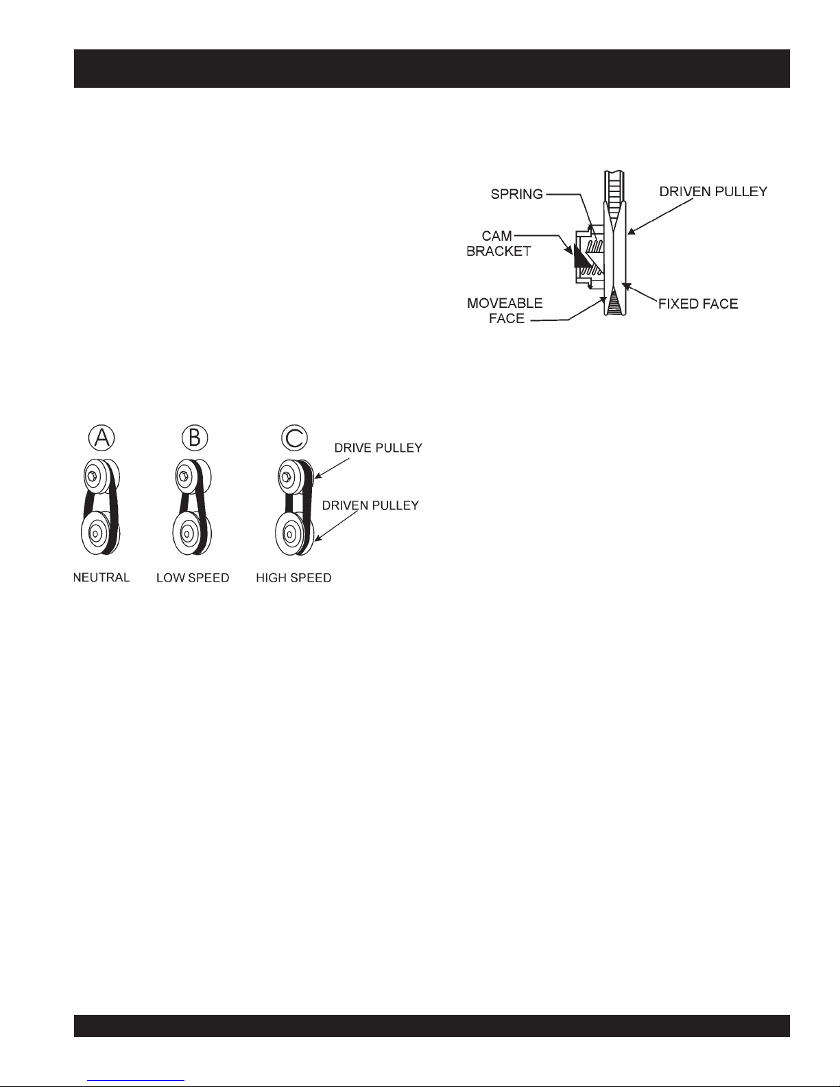
How It Works (Figure 17)
Condition A:
Condition B:
Condition C:
zz
z
Engine Idling
zz
zz
z
Drive Pulley: Small
zz
zz
z
Driven Pulley: Large
zz
zz
z
Belt: Loose and Stationary
zz
zz
z
Engine Accelerating
zz
zz
z
Drive Pulley: Small But Increasing
zz
zz
z
Driven Pulley: Large But Decreasing
zz
zz
z
Belt: Approaching Tightness
zz
zz
Engine At High Speed
z
zz
zz
z
Drive Pulley: Large
zz
zz
z
Driven Pulley: Small
zz
zz
z
Belt: Tight
zz
Figure 17. Pulley Conditions
The torque sensitive pulley (Figure 18) utilizes a spring and cam
bracket. Peak performance results from proper interaction between
the driven pulley spring and the ramp angle of the cam bracket.
Figure 18. Pulley Spring and Cam Bracket
Blade Pitch
Matching Blade Pitch for Both Sets of Blades
Sometimes it may be necessary to match blade pitch between
the two sets of blades. There are some signs that this may be
necessary. For example, the differences in pitch could cause a
noticeable difference in finish quality between the two sets of
blades. Or, the difference in blade pitch could make the machine
difficult to control. This is due to the surface area in contact with
the concrete (the blade set with the greater contact area tends to
stick to the concrete more).
™™
Single Pitch
™
™™
Clutch
This clutch system provides a high pulley ratio (a low gear- so to
speak) to start out and a low pulley ratio ( a high gear- so to
speak) for a high speed operation, with infinite variation between
the two.
This means that it will not be necessary to give
order to "break the blades/pans loose". The machine can slowly
be brought up to speed.
HHN 31V • RIDE-ON POWER TROWEL — OPERATION & PARTS MANUAL — REV. #5 (03/02/07) — PAGE 23
full throttle
On a Single Pitch™ trowel each spider assembly can be pitched
individually, forcing the operator to constantly make adjustments
on each pitch tower.
in
Page 24
HHN -31V — MAINTENANCE
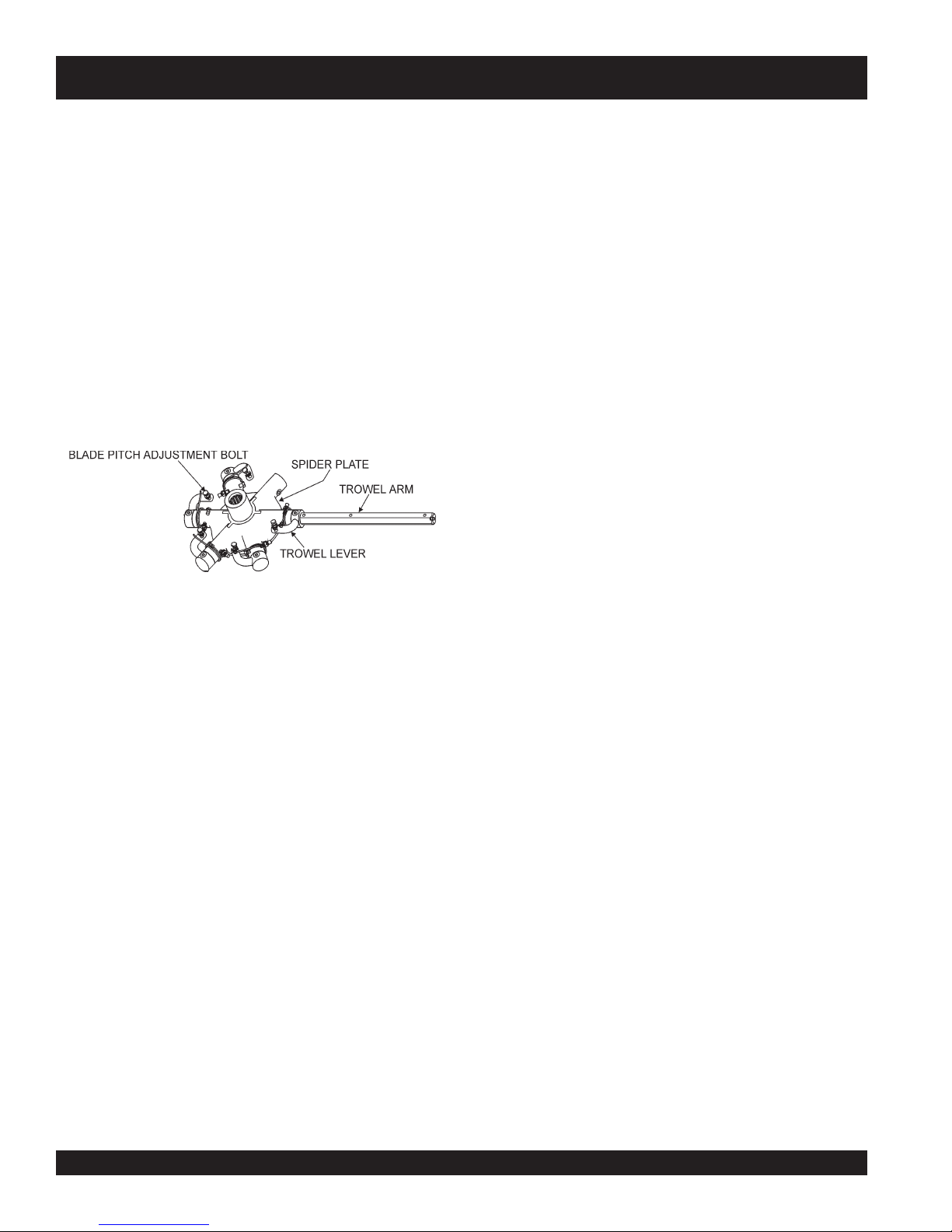
Blade Pitch Adjustment Procedure
The maintenance adjustment of blade pitch is an adjustment
that is made by a bolt (Figure 19) on the arm of the trowel blade
finger. This bolt is the contact point of the trowel arm to the lower
wear plate on the thrust collar. The goal of adjustment is to promote
consistent blade pitch and finishing quality.
There are some things to look for when checking to see if
adjustment is necessary. Is the machine wearing out blades
unevenly (i.e. one blade is completely worn out while the others
look new)? Does the machine have a perceptible rolling or
bouncing motion when in use? Look at the machine while it is
running, do the guard rings “rock up and down” relative to the
ground? Do the pitch control towers rock back and forth? These
are some of the indications that the blade pitch may need to be
adjusted using the adjustment bolts on the trowel blade finger.
It will be possible to adjust the “high” bolts down to the level of
the one that is not touching, or adjust the “low” bolt up to the level
of the higher ones. If possible, adjust the low bolt up to the level
of the rest of the bolts. This is the fastest way, but may not always
work. Verify that after adjustment, the blades pitch correctly.
Often times, if the blades are incorrectly adjusted, they will not
be able to pitch flat. This occurs when the adjusting bolts have
been raised too high. Conversely, sometimes the adjusting bolts
are too low and the blades cannot be pitched high enough for
finishing operations.
Changing A Blade
Whiteman recommends that all the blades on the entire machine
be changed at the same time. If only one or some of the blades
are changed at one time, the machine will not finish concrete
consistently and the machine may wobble or bounce.
1. Place the machine on a flat, level surface. Adjust the blade
pitch control to make the blades as flat as possible. Note
the blade orientation on the trowel arm. This is important
for ride-on trowels as the two sets of blades counter-rotate.
Lift the machine up, placing blocks under the main guard
ring to support it.
Figure 19. Blade Pitch Adjustment Bolt
The easiest and most consistent way to make this adjustment is
to use the Trowel Arm Adjustment Fixture (P.N. 9177) . This fixture
will allow consistent adjustment of the trowel arm fingers. It comes
with all the hardware necessary to properly accomplish this
maintenance and instructions on how to properly utilize this tool.
Adjusting the trowel arm fingers without a fixture requires a special
talent.
If a trowel arm adjustment fixture is not available and immediate
adjustment is necessary; we suggest the following procedure. If
you can see or feel which blade is pulling harder, adjust the bolt
that corresponds to that blade.
Another way to determine which blades need adjustment is to
place the machine on a flat surface and pitch the blades as flat
as possible. Now, look at the adjustment bolts. They should all
barely make contact with the lower wear plate on the spider. If
you can see that one of them is not making contact; some
adjustment will be necessary.
2. Remove the bolts and lock washers on the trowel arm, and
then remove the blade.
3. Scrape all concrete and debris from the trowel arm. This is
important to properly seat the new blade.
4. Install the new blade, maintaining the proper orientation
for direction of rotation.
5. Affix the bolts and lock washers.
6. Repeat steps 2-5 for all remaining blades.
Steering Adjustment
The steering assist adjustment is to be performed only by
qualified service technicians. For HHN steering adjustment
instructions, reference MQ Whiteman service bulletin 200925
Clean-Up
Never allow concrete to harden on the power trowel. Immediately
after use wash any concrete off the trowel with water, be careful
not to spray a hot engine or muffler. An old paint brush or broom
may help loosen any concrete that has started to harden.
Ttt
HHN 31V • RIDE-ON POWER TROWEL — OPERATION & PARTS MANUAL — REV. #5 (03/02/07) — PAGE 24
PAGE 24 — HTN 31V
Page 25

NOTE PAGE
HHN 31V • RIDE-ON POWER TROWEL — OPERATION & PARTS MANUAL — REV. #5 (03/02/07) — PAGE 25
Page 26

HHN -31V — TROUBLESHOOTING
GNITOOHSELBUORT.4ELBAT
MOTPMYS MELBORPELBISSOP NOITULOS
?noitcnuflamhctiwslliK
.lla
tatonrohguorgninnurenignE
?leuF
?noitingI
?smelborprehtO .launams’rerutcafunamenignetlusnoC
.gninoitcnuftonhctiwsllikytefaS
?stcatnocdaB .hctiwsecalpeR
?sedalB
?redipS
?snoitcennoceriwesooL .yrassecensaecalpeR.gniriwkcehC
?smraleworttneB
gneeht
.yltcerrocgninoitcnuf
iniF
.yrassecenfihctiwsecalper;detaes
.rabedalbehtotlellarapdna
.yletaidemmitiecalper,tnebylthgilsnevesismra
sirotarepoehtnehwgninoitcnufsihctiwsllikehttahterusekaM
otdeilppusgniebleufsierehterusekaM.metsysleufehttakooL
.deggolctonsiretlifleufehttahterusneotkcehC.eni
sidnarewopsahhctiwsnoitingiehttahterusneotkcehC
.nrowylevissecxeton,noitidnocdoognierasedalbniatrecekaM
ehtmorf)mm05("2nahtsselonerusaemdluohssedalbhs
onerusaemdluohssedalbobmoc,egdegniliartehtotrabedalb
thgiartsebdluohsedalbfoegdegniliarT.)mm98("5.3tahtssel
saelgnahctipemasehttateserasedalbllatahtkcehC
rofelbaliavasiloottnemtsujdadleifA.redipsehttaderusaem
tnempiuqElanoitpOees(smralewortehtfotnemtsujdathgieh
.)
ehtfoenofI.smraleworttnebrofylbmessaredipsehtkcehC
sllor,secnuob“lewortfI
nevenusekamro,etercnoc
.”etercnocnislriws
?hctipedalB
?tfahsniaM
elbitpecrepasahenihcaM
.gninnurelihwnoitomgnillor
?ekoY
?sedalB
?sgnihsubmraleworT
er
?ralloctsurhT
?gnihsubralloctsurhT
?nrowgniraebtsurhT
.yrassecen
.yrassecenfisnoitcurtsni
.tnioptnemhcatta
.sedalbrehtollasahctip
.ralloctsurhtehtnignihsubehtecalper
.yrassecensaekoyecalpeR.gniraebtsurhteht
ybenodebnacsihT.ssenthgitrofsgnihsubmralewortehtkcehC
"8/1nahteromsierehtfI.nwoddnapusmralewortehtgnivom
ebdluohssgnihsubeht,mraehtfopitehttalevartfo)mm2.3(
.emitemasehttadecalperebdluohssgnihsubllA.decalp
.redipsehtnotignitatorybralloctsurhtehtfossentalfehtkcehC
.ralloctsurhtehtecalper)mm5.0("20.0nahteromybseiravtifI
tlitnactifI.redipsehtnotignikcorybralloctsurhtehtkcehC
,].D.Oralloctsurhtehttaderusaemsa[)mm4.2("23/3nahterom
fiecalpeR.eerfgninnipssititahteesotgniraebtsurhtehtkcehC
noitcesecnanetniaMreptsujdA.hctiptnetsisnocrofsedalbkcehC
ebdluohsylbmessaxobraegehtfotfahstuptuoniamehT
dnathgiartsnurtsumtfahsniamehT.ssenthgiartsrofdekcehc
dipsehttadnuorfotuo)mm80.0("300.0nahteromebtonnac
re
noylnevesserpekoyehtfosregnifhtobtahterusekamotkcehC
emasehtevahotdetsujdasiedalbhcaetahterusneotkcehC
HHN 31V • RIDE-ON POWER TROWEL — OPERATION & PARTS MANUAL — REV. #5 (03/02/07) — PAGE 26
PAGE 26 — HTN 31V
Page 27

HHN -31V — TROUBLESHOOTING
)DEUNITNOC(GNITOOHSELBUORT.4ELBAT
MOTPMYS MELBORPELBISSOP NOITULOS
hctiwsffo/noretsamehtgnidulcni,snoitcennoclacirtcelellakcehC
.gnikrowton)lanoitpo(sthgiL
ton)lanoitpo(yarpstnadrateR
.gnikrow
rohgihootsitroffegnireetS
.evisnopsernu
?gniriW
?sthgiL .nekorbfiecalpeR.doogllitserasblubthgilfieesotkcehC
?tnadrateR
?gniriW
?hctiwsdaB
?pmupyarpsdaB
fotuosegaknilgnireetS
?tnemtsujda
?stnenopmocnroW .nrowrotneberatahtstrapllaecalpeR
.yrassecensaecalpeR
.yrassecen
.pmupehtecalper,doog
.strohsonhtiwnoitidnocdoognisigniriwfieesotkcehcdna
saknatlliF.tneserpsitnadratererusekamotknatehtkcehC
hctiwsffo/noretsamgnidulcni,snoitcennoclacirtcelellakcehC
.yrassecensagniriwdnastnenopmocecalpeR.snoitcennoc
.nekorbfiecalpeR.hctiwsffo/noretsamfoytiunitnocehtkcehC
tub,nodenrutsihctiwsehtnehwtneserpegatlovasahpmupfI
erapmupehtotsnoitcennoclacirtcelednaetarepotonseod
eeS.eldnahehtfoesabehttadnuofegaknilgntcennocehttsujdA
.529002nitelluBecivreS,"snoitcurtsnItnemtsujdAgnireetS"
?stovipxobraeG .sexobraegfotnemevomeerferusneotkcehC
sinoitisopgnitarepO
.elbatrofmocnu
esolcooteraseldnahlortnoC
.traparafootrorehtegot
hsiggulsrognippilshctulC
otgnidnopsernehwesnopser
.deepsenigne
hctiPniwTnoegakniL
.gnikrowton)lanoitpo(
.tsafoottuogniraewstleB
?tnemtsujda
?noisnettleB
?stlebnroW .ecalpeR
?hctulCytriD .hctulcehtnaelcdnaelbmessasiD
?xobraeg
?seldnahknarC
?trapdegamaD .yletaidemmistrapdegamadllaecalpeR
?noisneT
?rotareporoftsujdataeS .taesehtfotnorfehtnodetacolrevelhtiwtaestsujdA
fotuosegaknilgnireetS
?seldnahlortnoctneB .tneberatahtstrapllaecalpeR
?hctulCtuonroW .hctulceritneecalper,pirG-isoP.hctulcnoitcirfnoseohsecalpeR
?xobraegnisgniraeBnroW
nisraegnekorbronroW
sgniraebtfahsevirdnroW .yrassecenfiecalper,sgniraebenilevirdtcepsnI
?tnemngilayellupevirD
.tnemtsujdagnireetsnonoitceseeS
tlebevirdehtnidetonsaecnatsidretnectlebehttsujdA
.noitcestnemtsujda
,ytluciffidhtiwsetatortfahsfI.dnahybtfahstupnixobraegetatoR
tupniehtkcehc
.tesasamrow
.hctulc
.tcerrocsi
.yrassecenfiecalpeR.sgniraebtfahstuptuodna
setatortfahstuptuoxobraegehttahtyfirevotralucitrapnikcehC
dnaraegmrowehthtobecalpeR.detatorsitfahstupniehtnehw
sarafsanwoddehsuperaseldnahknarchtobtahterusekaM
.degagnesiegaknilehttahtserusnesihtgnioD.elbissop
ehthtiwdengilayltcerrocsiyellupevirdrewolfieesotkcehC
ecnatsidretnecenilevirdottfahsknarcehttahterusneotkcehC
HHN 31V • RIDE-ON POWER TROWEL — OPERATION & PARTS MANUAL — REV. #5 (03/02/07) — PAGE 27
Page 28

EXPLANATION OF CODE IN REMARKS COLUMN
The following section explains the different symbols and remarks
used in the Parts section of this manual. Use the help numbers
found on the back page of the manual if there are any questions.
The contents and part numbers listed in the parts section are
subject to change
guarantee the availibility of the parts listed.
Sample Parts List:
NO. PART NO. PART NAME QTY. REMARKS
1 12345 BOLT ....................... 1 .... INCLUDES ITEMS W/
2
*
2*12347 WASHER, 3/8 IN. ....1 ....
3 12348 HOSE .................... A/R .. MAKE LOCALLY
4 12349 BEARING ................ 1 .... S/N 2345B AND ABOVE
NO. Column
Unique Symbols - All items with same unique symbol
, #, +, %, or >) in the number column belong to the same
(
*
assembly or kit, which is indicated by a note in the “Remarks”
column.
Duplicate Item Numbers - Duplicate numbers indicate
multiple part numbers are in effect for the same general item,
such as different size saw blade guards in use or a part that
has been updated on newer versions of the same machine.
NOTE
without notice
WASHER, 1/4 IN. ...........
When ordering a part that has more
than one item number listed, check
the remarks column for help in
determining the proper part to order.
. Multiquip does not
NOT SOLD SEPARATELY
MQ-45T ONLY
QTY. Column
Numbers Used - Item quantity can be indicated by a number,
a blank entry, or A/R.
A/R (As Required) is generally used for hoses or other parts
that are sold in bulk and cut to length.
A blank entry generally indicates that the item is not sold
separately. Other entries will be clarified in the “Remarks”
Column.
REMARKS Column
Some of the most common notes found in the “Remarks”
*
Column are listed below. Other additional notes needed to
describe the item can also be shown.
Assembly/Kit
symbol will be included when this item is purchased.
Indicated by:
“INCLUDES ITEMS W/(unique symbol)”
Serial Number Break
range where a particular part is used.
Indicated by:
“S/N XXXXX AND BELOW”
“S/N XXXX AND ABOVE”
“S/N XXXX TO S/N XXX”
Specific Model Number Use
only with the specific model number or model number variant
listed. It can also be used to show a part is NOT used on a
specific model or model number variant.
Indicated by:
“XXXXX ONLY”
“NOT USED ON XXXX”
- All items on the parts list with the same unique
- Used to list an effective serial number
- Indicates that the part is used
PART NO. Column
Numbers Used - Part numbers can be indicated by a number,
a blank entry, or TBD.
TBD (To Be Determined) is generally used to show a part that
has not been assigned a formal part number at time of
publication.
A blank entry generally indicates that the item is not sold
separately or is not sold by Multiquip. Other entries will be
clarified in the “Remarks” Column.
HHN 31V • RIDE-ON POWER TROWEL — OPERATION & PARTS MANUAL — REV. #5 (03/02/07) — PAGE 28
“Make/Obtain Locally”
purchased at any hardware shop or made out of available
items. Examples include battery cables, shims, and certain
washers and nuts.
“Not Sold Separately”
purchased as a separate item and is either part of an
assembly/kit that can be purchased, or is not available for
sale through Multiquip.
PAGE 28 — HTN 31V
- Indicates that the part can be
- Indicates that an item cannot be
Page 29

HHN -31V — SUGGESTED SPARE PARTS
31 VANGUARD ENGINE
1 to 3 Units
Qty. P/N Description
4 ............ 0189 ................. HANDLE GRIP
4 ............ 2267 ................. HANDLE GRIP (RIGHT SIDE)
1 ............ 11430 ............... SWITCH
2 ............ 12460 ............... CABLE, PITCH
1 ............ 1617 ................. LEVER ASSY. TROWEL ADJUSTMENT
2 ............ 2737 ................. KNOB ASSY.
1 ............ 10208 ............... MUFFLER W/CLAMP
1 ............ 10434 ............... CLAMP
1 ............ 10463 ............... CLAMP
4 ............ 10937 ............... BELT (B-37)
1 ............ 11771 ............... BRACKET ENGINE THROTTLE CABLE
1 ............ 12168 ............... HEADER PIPE
1 ............ 2124 ................. THROTTLE CABLE
5 ............ 2829 ................. ARMS
2 ............ 9005 ................. LEVER TROWEL ARM (L.S.)
20 .......... 0166A .............. WASHER
20 .......... 1876 ................. JAM NUT
20 .......... 0164B .............. SCREW
5 ............ 11039 ............... BUSHING
2 ............ 9111 ................. SPRING (L.S.)
20 .......... 1875 ................. WASHER
20 .......... 1322 ................. SCREW ASSY., ARM RETAINING
2 ............ 12611 ............... SPIDER PLATE
20 .......... 1162A .............. CAP GREASE FITTING
20 .......... 16602 ............... SCREW (HHC 3/8 -16 X 3/8)
20 .......... 1456 ................. NUT (3/8 -16)
20 .......... 12097 ............... SCREW (SQH 3/8-16 X 1 3/4 CONE)
2 ............ 2143 ................. SPRING (R.S.)
2 ............ 1986 ................. LEVER TROWEL ARM (R.S.)
2 ............ 12005 ............... SAFETY KILL SWITCH
20 .......... 0181B .............. WASHER 1/4 IN
2 ............ 11418 ............... FUEL CAP/GUAGE
20 .......... 4514 ................. SCREW (HHC 1/4-20 X 5/8)
Qty. P/N Description
2 ............ 2124 ...................... CABLE THROTTLE (RT)
10 .......... 10031 .................... WASHER 1/4 IN.
2 ............ 11692 .................... BRACKET BATTERY
2 ............ 11693 .................... BOLT BATTERY
6 ............ 2509 ...................... WING NUT
2 ............ 12548 .................... SPRAY PUMP
2 ............ 2108 ...................... CAP SPRAY TANK
2 ............ 10958 .................... SWITCH, IGNITION
1 ............ 19301 .................... TERMINAL STRIP (10-POLE)
1 ............ 2580 ...................... CHOKE CABLE
1 ............ 2673 ...................... CIRCUIT BREAKER 30 AMP, 12V
2 ............ 4682 ...................... TOGGLE SWITCH
2 ............ 8381 ...................... BOOT, TOGGLE SWITCH
1 ............ 11792 .................... ACCESSORY SOLENOID
4 ............ 11078 .................... KEYS, IGNITION (SWITCH)
2 ............ 2655 ...................... HOUR METER
NOTE
Part numbers on this Suggested
Spare Parts List may supercede/
replace the P/N shown in the text
pages of this book.
HHN 31V • RIDE-ON POWER TROWEL — OPERATION & PARTS MANUAL — REV. #5 (03/02/07) — PAGE 29
Page 30

NAME PLATE AND DECALS
HHN -31V — NAME PLATE AND DECALS
HHN 31V • RIDE-ON POWER TROWEL — OPERATION & PARTS MANUAL — REV. #5 (03/02/07) — PAGE 30
PAGE 30 — HTN 31V
Page 31

HHN -31V — NAME PLATE AND DECALS
NAME PLATE AND DECALS
NO PART NO PART NAME QTY. REMARKS
1 11246 DECAL: LIFT .................................................. 2............ PART OF DECAL KIT12620
2 1499 DECAL: MQ WHITEMAN (RED/TOWER) 2
3 2634 DECAL: DANGER (COMPRESSION) 2
4 11246 DECAL: LUBRICATION .................................. 4 ............ PART OF DECAL KIT12620
5 12571 DECAL: OPERATING LIGHTS 1
6 11247 DECAL: HELMET, HAND AND FOOT ............ 1 ............ PART OF DECAL KIT12620
7 11246 DECAL: RADIATING HEAT ............................. 1 ............ PART OF DECAL KIT12620
8 20198 DECAL: HHN SERIES 1
9 13118 DECAL: POWDER COATED 1
10 10818 DECAL: MQ WHITEMAN (WHITE/PANEL) .....1
11 DECAL: NAME PLATE .................................... 1 ............ CONTACT MQ SERVICE DEPT W/ MODEL & S/N
12 11246 DECAL: CHECK HYDRAULIC OIL.................. 2............ PART OF DECAL KIT12620
13 11246 DECAL: GEAR DRIVE ....................................2 ............ PART OF DECAL KIT12620
14 11246 DECAL: BELT DRIVE ...................................... 1 ............ PART OF DECAL KIT12620
SEE DECAL ILLUSTRATIONS ON PAGE 10.
HHN 31V • RIDE-ON POWER TROWEL — OPERATION & PARTS MANUAL — REV. #5 (03/02/07) — PAGE 31
Page 32

HHN -31V — PIVOT/GEAR BOX-RIGHT SIDE ASSY.
PIVOT/GEAR BOX- RIGHT SIDE ASSY.
VIEW FROM OPERATOR’S SEAT
1
2
R
E
D
W
O
P
D
E
T
C
A
O
3
1
5
4
3
1
5
6
4
8
RIGHT-SIDE
GEARBOX
9
NOTES:
SCREWS ARE PART OF
RIGHT-SIDE GEAR BOX
ASSEMBLY. TO ORDER
1
HHN 31V • RIDE-ON POWER TROWEL — OPERATION & PARTS MANUAL — REV. #5 (03/02/07) — PAGE 32
PAGE 32 — HTN 31V
Page 33

HHN -31V — PIVOT/GEAR BOX-RIGHT SIDE ASSY.
PIVOT/GEAR BOX- RIGHT SIDE ASSY.
NO PART NO PART NAME QTY. REMARKS
1 1023 SCREW, HHC 3/8 -16 X 1-1/4 8
2 0166A WASHER, LOCK 3/8 MED 8
3 9154 SCREW 4 PART OF GEAR BOX
4 12713 ROCKER BLOCK 2
5 12725 BLOCK, ROCKER 2
6 12716 TRUNNION W/A 1
7 12704 GEARBOX, COMPLETE 1
8 12859 PLATE G.B. SPACER 1
9 12856 BRACKET, DIRECTION CONTROL 1
HHN 31V • RIDE-ON POWER TROWEL — OPERATION & PARTS MANUAL — REV. #5 (03/02/07) — PAGE 33
Page 34

PIVOT/GEAR BOX- LEFT SIDE ASSY.
VIEW FROM OPERATOR’S SEAT
HHN -31V — PIVOT-LEFT SIDE ASSY.
1
2
R
E
D
W
O
P
D
E
T
C
A
O
1
3
1
3
5
1
4
3
1
8
LEFT-SIDE
GEARBOX
9
2
10
2
6
5
NOTES:
SCREWS ARE PART OF
1
LEFT-SIDE GEAR BOX
ASSEMBLY. TO ORDER
SCREWS USE P/N 9154.
USE ITEMS 9, 10 AND 11
TO MOUNT RIGHT-SIDE
2
GEAR BOX.
11
2
HHN 31V • RIDE-ON POWER TROWEL — OPERATION & PARTS MANUAL — REV. #5 (03/02/07) — PAGE 34
PAGE 34 — HTN 31V
Page 35

HHN -31V — PIVOT-LEFT SIDE ASSY.
PIVOT/GEAR BOX- LEFT SIDE ASSY.
NO PART NO PART NAME QTY. REMARKS
1 1023 SCREW, HHC 3/8 -16 X 1-1/4 8
2 0166A WASHER, LOCK 3/8 MED 8
3 9154 SCREW 4 PART OF GEAR BOX
4 12719 PIVOT, GEAR BOX W/A 1
5 12725 BLOCK, ROCKER 2
6 12859 PLATE G.B. SPACER 1
7 12703 GEARBOX, COMPLETE 1
8 12856 BRACKET, DIRECTION CONTROL 1
9 0176 NUT, NYLOC 1/2-13 2 USE ON RS GEAR BOX
10 0447 WASHER, FLAT 1/2 SAE 2 USE ON RS GEAR BOX
11 2549 SCREW, HHC 1/2-13 X3 2 USE ON RS GEAR BOX
HHN 31V • RIDE-ON POWER TROWEL — OPERATION & PARTS MANUAL — REV. #5 (03/02/07) — PAGE 35
Page 36

GEARBOX ASSY.
HHN -31V — GEAR BOX ASSY.
15
44
41
21
31
11
35
1
20
4
45
30
29
17
14
36
9
3
1
5
24
39
32
7
28
20
13
30
4
23
42
21
31
4
2
22
10
24
25
3
18
6
26
32
43
16
8
37
27
33
2
38
1
18
4
24
43
12
19
2
4
USE SILICONE SEALANT
1
UNDER RETAINER; LOCTITE #30518.
TORQUE TO 30 FT-LBS.
2
USE SILICONE SEALANT
3
AT SPLICE; LOCTITE #30518.
BEARING CONE FOR OLD STYLE
4
GEARBOX IS NOT INCLUDED IN KIT.
19
HHN 31V • RIDE-ON POWER TROWEL — OPERATION & PARTS MANUAL — REV. #5 (03/02/07) — PAGE 36
PAGE 36 — HTN 31V
Page 37

HHN -31V — GEAR BOX ASSY.
GEARBOX ASSY.
NO PART NO PART NAME QTY. REMARKS
1$ 0166 A WASHER, LOCK 3/8 MED 16
2$ 0181 B WASHER, LOCK 1/4 MED 8
3$ 0205 SCREW, HHC 3/8-16 X 1 8
4$ 0730 SCREW, HHC 1/4-20 X 1 8
5$ 10136 WASHER, FLAT, 3/8 SAE 8
6$ 11584 SIGHT GLASS, 3/4 MALE PIPE 1
7$ 11682 FITTING, PLUG, 1/8 MP SQ HEAD 1
8$ 12599 CASE, GEAR MACHINED 1
9$ 12600 COVER, GEAR BOX 1
10$ 12601 CAP, GEARBOX INPUT 1
11$ 12602 CAP, GEARBOX IDLER 2
12$% HUB, INPUT SHAFT ............................................ 1 ................... NOT AVAILABLE SEPARATELY
13$+ GEAR, 85T HELICAL........................................... 1 ................... NOT AVAILABLE SEPARATELY
14$
*
15$
*
16$% PINION, 15T BEVEL ............................................ 1 ................... NOT AVAILABLE SEPARATELY
17$+ SHAFT, OUTPUT ................................................ 1 ................... NOT AVAILABLE SEPARATELY
18 12691 BEARING, CONE TIMKEN #M84249 .................. 2 ................... OLD STYLE GEARBOX
18$% 21803 BEARING, CONE SKF 32305 J2 ....................... 2 ................... NEW STYLE GEARBOX
19 12692 BEARING, CUP TIMKEN #M84210..................... 2 ................... OLD STYLE GEARBOX
20 12693 BEARING, CONE TIMKEN #2793 ....................... 2 ................... OLD STYLE GEARBOX
20$
21 12694 BEARING, CUP TIMKEN #2729 .......................... 2 ................... OLD STYLE GEARBOX
22$% 12696 COUPLER, GEARBOX 1
23$ 12697 PIN, DOWEL 0.375/.3752 X 3/4 2
24$%# 12698 O RING, SIZE - 151 BUNA N 4
25$# 12700 SEAL, CASE 0-RING HHN 0.103 X 46. 38 1
26$%# 12701 SEAL, NATIONAL #471424 1
27$# 12702 SEAL, NATIONAL #470682 1
28$
29$+ 12736 KEY, HARDENED 3/8 X 1-1/2 1
30 12796 BEARING, CONE TIMKEN #26882 ..................... 2 ................... OLD STYLE GEARBOX
30$+ 21801 BEARING, CONE SKF 33109 Q ......................... 2 ................... NEW STYLE GEARBOX
31 12797 BEARING, CUP TIMKEN #26823 ........................ 2 ................... OLD STYLE GEARBOX
32$ 20932 SHIM, INPUT. 0.002 THICK 3
33$% 1313 SCREW, FHSC 3/8 - 24 X 3/4 PLAIN 1
34$% 26034 KEY, 3/16 X 17/32 1
35$ 4196 SCREW, HHC 3/8 - 16 X 3/4 8
36$ 911064 FITTING, PLUG 1/2 MP SQ HEAD 1
37$ 911329 FITTING, PLUG 3/8 MP MAGNETIC 2
38$% 9120 RETAINER, DRIVEN PULLEY 1
39$ 9154 SCREW, HHC 3/8 - 16 X 1-3/4 4
40 20933 KIT, BEARING/SEAL HHN HELICAL ................... 1 ................... INCLUDES ITEMS W/ #
41 21854 GEARBOX ASSY., RIGHT ................................... 1 ................... INCLUDES ITEMS W/ $
42 21853 GEARBOX ASSY., LEFT ...................................... 1 ................... INCLUDES ITEMS W/ $
43 21853854INPUT KIT, INPUT PINION/HUB/COUPLER .................. 1 ................... INCLUDES ITEMS W/ %
44 21853854INTER KIT, INTER PINION/GEAR .................................. 1 ................... INCLUDES ITEMS W/
45 21853854OUTER KIT, OUTPUT SHAFT/GEAR .............................. 1 ................... INCLUDES ITEMS W/ +
21802 BEARING, CONE SKF 32307 J2 ........................ 2 ................... NEW STYLE GEARBOX
*
12735 KEY, 3/8 X 3/4 1
*
PINION, 17T HELICAL ........................................ 1 ................... NOT AVAILABLE SEPARATELY
GEAR, 60T HELICAL ........................................... 1 ................... NOT AVAILABLE SEPARATELY
*
HHN 31V • RIDE-ON POWER TROWEL — OPERATION & PARTS MANUAL — REV. #5 (03/02/07) — PAGE 37
Page 38

HHN -31V — CONTROL STEERING (ASSIST)
HHN 31V • RIDE-ON POWER TROWEL — OPERATION & PARTS MANUAL — REV. #5 (03/02/07) — PAGE 38
PAGE 38 — HTN 31V
Page 39

HHN -31V — CONTROL STEERING (ASSIST)
CONTROL STEERING (ASSIST)
NO PART NO PART NAME QTY. REMARKS
1 0131 A SCREW, HHC 1/4-20 X 3/4 12
3 0447 WASHER, FLAT, 1/2 SAE 12
6 10024 NUT, NYLOC 1/4-20 16
7 10133 NUT, NYLOC 3/8-16 8
8 10136 WASHER, FLAT,3/8 SAE 16
9 10176 NUT, NYLOC 1/2-13 13
10 1023 SCREW, HHC 3/8-16 X 1 1/4 8
11 11127 LEVER, STEERING CONTROL W/A 2
13 11139 BEARING, FLANGE HOUSING 40M-2 6
14 11141 SPACER, ROD END 5
15 11142 ROD END, 1/2-20 MALE RH 9
16 11143 ROD END, 1/2-20 FEMALE RH 7
19 11146 NUT, HEX JAM 1/2-20 11
21 11150 BEARING, SB-201-8 6
22 11170 SCREW, HHC 1/2-20 X 1.1/2” 2
25 11205 ROD, L/R MOTION 1
26 12193 LEVER, L/R CONTROL W/A 1
34 5054 A WASHER, LOCK, 1/2 MED. 2
36 6159 A SCREW, HHC 1/2-13 X 2 13
HHN 31V • RIDE-ON POWER TROWEL — OPERATION & PARTS MANUAL — REV. #5 (03/02/07) — PAGE 39
Page 40

HHN -31V — CONTROL STEERING (ASSIST)
HHN 31V • RIDE-ON POWER TROWEL — OPERATION & PARTS MANUAL — REV. #5 (03/02/07) — PAGE 40
PAGE 40 — HTN 31V
Page 41

HHN -31V — CONTROL STEERING (ASSIST)
CONTROL STEERING (ASSIST)
NO PART NO PART NAME QTY. REMARKS
2 2267 GRIP HANDLE, LEFT-RIGHT 2
3 0447 WASHER, FLAT, 1/2 SAE 12
4 0735 BEARING, CONE, TIMKEN #A6075 4
5 0735 A BEARING, CUP, TIMKEN #A6157 4
8 10136 WASHER, FLAT,3/8 SAE 16
9 10176 NUT, NYLOC 1/2-13 13
12 11138 BEARING, P-BLOCK HOUSING 47MPB 4
14 11141 SPACER, ROD END 5
15 11142 ROD END, 1/2-20 MALE RH 9
16 11143 ROD END, 1/2-20 FEMALE RH 7
17 11144 SCREW, SHC 1/2-20 X 2 PLTD 1
18 11145 SCREW. SHC 1/2-20 X 3 PLTD 1
19 11146 NUT, HEX JAM 1/2-20 11
20 11149 BEARING, SB-204-12 4
22 11170 SCREW, HHC 1/2-20 X 1.1/2” 2
23 11173 THREADPIECE, 1/2-20 X 2 PLTD 1
24 11177 HANDLE TUBE, UPPER 2
27 12200 ASSIST ASM, STEERING SPRING 2
28 12904 STEERING CONTROL W/A RS ASSIST 1
29 12903 STEERING CONTROL W/A LS ASSIST 1
30 12425 HANDLE , LOWER W/A 2
31 12426 NUT, SLOTTED 3/4-16 PLATED 2
32 2197 NUT, ACORN 1/4-20 2
33 2219 PIN, COTTER 1/8 X 1 1/2 2
34 5054 A WASHER, LOCK, 1/2 MED. 2
35 5277 SCREW, HHC 1/4-20 X 1 1/2 2
36 6159 A SCREW, HHC 1/2-13 X 2 13
37 8151 WASHER, FLAT, 3/4 SAE 4
38 11430 SWITCH, PUSHBUTTON 1
4
1 0166A WASHER, LOCK, 3/8 MED 2
2 0183 PIN, COTTER 1/8 X 1 1/4 4
HHN 31V • RIDE-ON POWER TROWEL — OPERATION & PARTS MANUAL — REV. #5 (03/02/07) — PAGE 41
Page 42

HHN -31V — TWIN PITCH ASSY. (LEFT/RIGHT)
HHN 31V • RIDE-ON POWER TROWEL — OPERATION & PARTS MANUAL — REV. #5 (03/02/07) — PAGE 42
PAGE 42 — HTN 31V
Page 43

HHN -31V — TWIN PITCH ASSY. (LEFT/RIGHT)
TWIN PITCH ASSY. (LEFT/RIGHT)
NO PART NO PART NAME QTY. REMARKS
+% 0126 B KEY, WOODRUFF #9 1
1
2+% 0161C WASHER, LOCK 5/16 MED 1
3
+% 0181 B WASHER, LOCK, 1/4 MED 4
*
+% 0655 SCREW, HHC 5/16 – 18 X 3/4 1
4
5+% 0685 SCREW, SHS 5/16 – 18 X 5/16 1
6
+% 0948 WASHER, FLAT, 1/4 SAE 1
+% 10382 BOLT, SHOULDER, 3/8 X 3/8 LONG 1
7
8+ 10511 SHAFT, PITCH CONTROL, LH TPC .................. 1 ..................... LEFT SIDE ONLY
9
+% 10512 RING, SNAP, TRUARC 5160 – 75 1
+% 10546 HOUSING, PITCH CONTROL, 1-3/4 1
10
11
+ 10722 SLIDE BLOCK, LH PITCH CON ......................... 1 ..................... LEFT SIDE ONLY
12+% 10723 PIN, SPIROL 3/16 X 1 3/8 HD 1
+% 1116 NUT, BRASS JAM 5/16 – 18 2
13
14
+% 11583 U-JOINT, PITCH CONTROL 2
*
15
+% 1162 A CAP, GREASE ZERK 2
*
+% 12460 CABLE, PITCH ASM 1
16
19
+% 20005 SHAFT, TWIN PITCH 1
20
+% 11654 PIN, ROLL 1/8 X 1 PLATED ............................... 5 ..... QTY. INCLUDES USAGE ON BOTH TWIN PITCH
*
22+% 1529 GEAR, MASTER, TPC 1
23+% 1530 GEAR, SLAVE, TPC 1
24
+% 1578 KEY, WOODRUFF, #3......................................... 9 ..... QTY. INCLUDES USAGE ON BOTH TWIN PITCH
*
25+% 1579 SCREW, HHC 1/4 – 20 X 1/2 1
26+% 1586 PIN, ROLL 1/8 X 3/4 1
27+% 1604 BEARING, BALL 1
28+% 1612 BEARING, ALUM – PITCH CONTR 1
29
+% 1733 WASHER, 1/32 X 1/2 HARDENED 8
*
30+% 2007 SHAFT 1
33+% 2169 BEARING, THRUST, TORR #NTA 1220 1
34+% 2170 BEARING, RACE, TORR #TRA 1220 3
35+% 2311 SPACER, 3/4 X 1/2 X 0.8L 1
36+% 2367 SET COLLAR ..................................................... 1 ..................... INCLUDES ITEM 5
37+% 2620 SCREW, BHC 10 – 24 X 5/8 4
38
+% 2621 ZERK, GREASE STR 1/4 – 28 2
*
40+% 2649 COVER, PITCH CONT HOUSING 1
57 1617 LEVER ASSY, TROWEL ADJUSTMENT ............ 1 ..................... INCLUDES ITEMS W/#
58 2300 DECAL, AL PITCH, RH 1
59 2332 DECAL, AL PITCH, LH 1
60# 4014 SCREW, 2-3/16 P-K TYPE U DRIVE 2
61#$ 4403 CRANK KNOB 1
62#$ 3231 SPACER 1
63# 1615 CRANK LEVER 1
64#$ 1733 HARDENED WASHER 1
65#$ 1616 SHOULDER BOLT 1
66# 0185 SCREW, SHSS 3/8 – 16 X 3/8" 1
67# 1528 SCREW, SHSS 1/4 – 20 X 5/16" 1
68% 10510 SHAFT, PITCH CONTROL, RH TPC .................. 1 ..................... RIGHT SIDE ONLY
69% 10721 SLIDE BLOCK, RH PITCH CONTROL ............... 1 ..................... RIGHT SIDE ONLY
70 10114 WASHER, EXT. SHKP, #8 4
71 1162A CAP, GREASE ZERK/2 1
72 2621 FITTING GREASE 1
73 2737 KNOB, KIT .......................................................... 1 ..................... INCLUDES ITEMS W/$
.................................................................................... ASSEMBLIES, AND MITER BOX SHAFTS
.................................................................................... ASSEMBLIES, AND MITER BOX SHAFTS
NOTE:
Indicated quanties are for one pitch tower. If ordering for two pitch towers double the quantity.
HHN 31V • RIDE-ON POWER TROWEL — OPERATION & PARTS MANUAL — REV. #5 (03/02/07) — PAGE 43
Page 44

HHN -31V — TWIN PITCH ASSY. (LEFT/RIGHT)
HHN 31V • RIDE-ON POWER TROWEL — OPERATION & PARTS MANUAL — REV. #5 (03/02/07) — PAGE 44
PAGE 44 — HTN 31V
Page 45

HHN -31V — TWIN PITCH ASSY. (LEFT/RIGHT)
TWIN PITCH ASSY. (LEFT/RIGHT)
NO PART NO PART NAME QTY. REMARKS
+% 0181 B WASHER, LOCK, 1/4 MED 4
3
*
14
+% 11583 U-JOINT, PITCH CONTROL 2
*
15
+% 1162 A CAP, GREASE ZERK 2
*
+% 12460 CABLE, PITCH ASM 1
16
17 10548 TUBE, PITCH CONTROL W/A 1
20
+% 11654 PIN, ROLL 1/8 X 1 PLATED ............................... 5 ..... QTY. INCLUDES USAGE ON BOTH TWIN PITCH
*
21 1499 DECAL, WHITEMAN 1
22+% 1529 GEAR, MASTER, TPC 1
+% 1530 GEAR, SLAVE, TPC 1
23
24
+% 1578 KEY, WOODRUFF, #3......................................... 9 ..... QTY. INCLUDES USAGE ON BOTH TWIN P ITCH
*
29
+% 1733 WASHER, 1/32 X 1/2 HARDENED 8
*
31 2012 SLEEVE, ADJ – LONG, RIDER 1
32 2156 SPRING, COIL 1
38
+% 2621 ZERK, GREASE STR 1/4 – 28 2
*
39 2634 DECAL, PITCH TOWER 1
41 0202 SCREW, HHC 5/16 – 18 X 1 4
42 0300 B WASHER, FLAT, 5/16 SAE 4
43
44
45
46
47
48
49
51
52
53 5283 NUT, NYLOC 5/16 – 18 4
56 11655 MITER BOX ASSY (HHN) ................................... 1 ..................... INCLUDES ITEMS W/
0730 SCREW, HHC 1/4 – 20 X 1 8
*
11653 SLEEVE W/U JOINT 1
*
1577 SET COLLAR, 1/2 2
*
1987 MITER BOX, PITCH CONTROL 1
*
1988 MITER BOX, BEARING CAP RIDERS 2
*
2021 SHAFT, MITER VERT 1
*
2022 SHAFT, MITER VERTICAL .................................3 ..... QTY. INCLUDES USAGE ON BOTH TWIN PITCH
*
2845 SHAFT, MITER BOX HORIZ (HNN)1
*
4514 SCREW, HHC 1/4 – 20 X 5/8 4
*
.................................................................................... ASSEMBLIES, AND MITER BOX SHAFTS
.................................................................................... ASSEMBLIES, AND MITER BOX SHAFTS
.................................................................................... ASSEMBLIES, AND MITER BOX SHAFTS
*
HHN 31V • RIDE-ON POWER TROWEL — OPERATION & PARTS MANUAL — REV. #5 (03/02/07) — PAGE 45
Page 46

ENGINE (VANGUARD)
HHN 31V-31V-TC — ENGINE (VANGUARD)
HHN 31V • RIDE-ON POWER TROWEL — OPERATION & PARTS MANUAL — REV. #5 (03/02/07) — PAGE 46
PAGE 46 — HTN 31V
Page 47

HHN 31V-31V-TC — ENGINE (VANGUARD)
ENGINE (VANGUARD)
NO PART NO PART NAME QTY. REMARKS
1 0937 NUT, HEX 10-32 2
2 10237 WASHER, EXT. SHKP. #10 1
3 11710 SPACER, ENG THROTTLE 1
4 8133 SCREW, RHM 10-32 X 3/4 1
5 2203 WASHER, FLAT #10 1
6 2153 ROD END, 10-32 FEMALE RH 1
7 11771 BRACKET, ENGINE THROTTLE CABLE 1
8 0161 C WASHER, LOCK, 5/16 MED. 8
9 2299 SCREW, HHC M8-1.25 X 16mm 3
10 2124 CABLE, THROTTLE (RT) 1
11 10087 NUT, NYLOC 1/2-20 THIN 1
12 0447 WASHER, FLAT 1/2 SAE 1
13 0202 SCREW, HHC 5/16-18 X 1 3
14 0300 B WASHER, FLAT, 5/16 SAE 2
15 5283 NUT, NYLOC 5/16-18 3
16 2866 SCREW, HHC M8-1.25 X 20mm 4
17 12844 MOUNT, 31V ENGINE W/A 1
18 19468 GROMMET, MINOR PN Z-4004 2
19 12199 WASHER, FLAT 2
20 0183 COTTER OIN 2
HHN 31V • RIDE-ON POWER TROWEL — OPERATION & PARTS MANUAL — REV. #5 (03/02/07) — PAGE 47
Page 48

ENGINE (VANGUARD)
37 12225 HOSE , AIR CLEANER MT
1
HHN -31V — ENGINE (VANGUARD)
HHN 31V • RIDE-ON POWER TROWEL — OPERATION & PARTS MANUAL — REV. #5 (03/02/07) — PAGE 48
PAGE 48 — HTN 31V
Page 49

HHN -31V— ENGINE (VANGUARD)
ENGINE (VANGUARD)
NO PART NO PART NAME QTY. REMARKS
1 10434 CLAMP, 2” HOSE 2
2 12225 HOSE , AIR CLEANER MT 1
3 0948 WASHER, FLAT, 1/4 SAE 8
4 0161 C WASHER, LOCK, 5/16 MED. 6
5 0730 SCREW, HHC 1/4-20 X 1 2
6 12464 SCREW, HHC M6-1.0 X 16mm 3
7 11900 MOUNT, RADIATOR OVERFLOW 1
8 12102 MOUNT, AIR CLEANER W/A 1
9 19266 BLIND NUT 2
10 12103 CLAMP, 31V AIR CLEANER ASM 1
HHN 31V • RIDE-ON POWER TROWEL — OPERATION & PARTS MANUAL — REV. #5 (03/02/07) — PAGE 49
Page 50

ENGINE (VANGUARD)
HHN -31V — ENGINE (VANGUARD)
HHN 31V • RIDE-ON POWER TROWEL — OPERATION & PARTS MANUAL — REV. #5 (03/02/07) — PAGE 50
PAGE 50 — HTN 31V
Page 51

HHN -31V — ENGINE (VANGUARD)
ENGINE (VANGUARD)
NO PART NO PART NAME QTY. REMARKS
1 20089 MUFFLER, 31V 1
2 12848 EXHAUST FLANGE NUT 4
3 12847 EXHAUST GASKET 1
4 10114 WASHER, EXT. SHKP, #8 2
5 0655 SCREW, HHC 5/16-18 X 3/4 2
6 11819 SCREW, HHC 1/4-20 X 3/4 W/WASH 7
7 12545 PLATE, BELT GUARD SIDE 1
8 11534 NUT, “U” TYPE, 1/4-20 8
9 0161 C WASHER, LOCK, 5/16 MED. 4
10 1605 SCREW, HHC M8-1.25 X 25mm 4
11 20082 BELT GUARD/MUFFLER SUPPORT W/COMET 1
12 20098 PLATE, BELT GUARD REAR 1
11
1
HHN 31V • RIDE-ON POWER TROWEL — OPERATION & PARTS MANUAL — REV. #5 (03/02/07) — PAGE 51
Page 52

ENGINE (VANGUARD)
HHN -31V — ENGINE (VANGUARD)
HHN 31V • RIDE-ON POWER TROWEL — OPERATION & PARTS MANUAL — REV. #5 (03/02/07) — PAGE 52
PAGE 52 — HTN 31V
Page 53

HHN -31V — ENGINE (VANGUARD)
ENGINE (VANGUARD)
NO PART NO PART NAME QTY. REMARKS
1 20138 BELT, CVT-VANGUARD COMET....................................... 2 ........................... ORDER 2 BELTS FOR SPARES
2 60049 TRIM EDGE, 1/32 (62B3-1/32) 1.50 FT.
3 12450 GUARD, RADIATOR (31 VAN) 1
4 SCREW ............................................................................. 2 .......................... INCLUDED W/RADIATOR
5 SCREW ............................................................................. 2 .......................... INCLUDED W/RADIATOR
6 WASHER ........................................................................... 2 .......................... INCLUDED W/RADIATOR
7 3911758 ADAPTOR, CLUTCH 31 HP VANGUARD 1
8 20046 SCREW, HHC M8 125 X 25 MM GRADE 10.9 5
9 12878 CLUTCH, CVT 1-7/16 COMET 1
10 20215 .415 OD X 21/32 ID X 2-1/16L 1
11 4703 WASHER, LOCK, 5/8 MED 1
12 20057 SCREW, HHC 5/8-18 X4 1
13 11292 ENGINE, BRIGGS 31 HP,DM950G 1
HHN 31V • RIDE-ON POWER TROWEL — OPERATION & PARTS MANUAL — REV. #5 (03/02/07) — PAGE 53
Page 54

HHN -31V — ENGINE (VANGUARD)
ENGINE (VANGUARD)
HHN 31V • RIDE-ON POWER TROWEL — OPERATION & PARTS MANUAL — REV. #5 (03/02/07) — PAGE 54
PAGE 54 — HTN 31V
Page 55

HHN -31V — ENGINE (VANGUARD)
ENGINE (VANGUARD)
NO PART NO PART NAME QTY. REMARKS
1 4514 SCREW, HHC 1/4-20 X 5/8 4
2 0161 C WASHER, LOCK, 5/16 MED. 4
3 0948 WASHER, FLAT, 1/4 SAE 8
4 11418 FUEL CAP/GAUGE (10.5”) 1
5 12404 TANK, HNN 5GAL 1
6 19633 BUSHING, RUBBER FUEL DAPCO10672 1
7 19661 VALVE , FUEL DRAIN DAPCO 11478 1
8 19473 CLAMP, WORM HOSE, #4 (1/4-5/8) 6
9 60013 HOSE, .25id RUBBER FUEL LINE 3
10 11984 IN-LINE FUEL FILTER 5/16 1
11 10024 NUT, NYLOC 1/4-20 2
12 0131 A SCREW, HHC 1/4-20 X 3/4 2
13 12497 FUEL PUMP 1
HHN 31V • RIDE-ON POWER TROWEL — OPERATION & PARTS MANUAL — REV. #5 (03/02/07) — PAGE 55
Page 56

ENGINE (VANGUARD)
HHN -31V — ENGINE (VANGUARD)
HHN 31V • RIDE-ON POWER TROWEL — OPERATION & PARTS MANUAL — REV. #5 (03/02/07) — PAGE 56
PAGE 56 — HTN 31V
Page 57

HHN -31V — ENGINE (VANGUARD)
ENGINE (VANGUARD)
NO PART NO PART NAME QTY. REMARKS
1 20051 CRADLE, ENGINE W/A 1
2 10136 WASHER, FLAT, 3/8 SAE 8
3 1063 NUT NYLOC 3/8-24 4
4 8156 SCREW, HHC 3/8-16 X 2-1/2 4
5 12832 WASHER, VIBRATION SNUB 4
6 12831 MOUNT, ENGINE VIBRATION 4
7 10133 NUT, NYLOC 3/8-18 4
HHN 31V • RIDE-ON POWER TROWEL — OPERATION & PARTS MANUAL — REV. #5 (03/02/07) — PAGE 57
Page 58

DRIVE ASSY.
HHN -31V — DRIVE ASSY.
HHN 31V • RIDE-ON POWER TROWEL — OPERATION & PARTS MANUAL — REV. #5 (03/02/07) — PAGE 58
PAGE 58 — HTN 31V
Page 59

HHN -31V — DRIVE ASSY.
DRIVE ASSY.
NO PART NO PART NAME QTY. REMARKS
1 0126 KEY, WOODRUFF 4
2 0161C WASHER, LOCK 5/16 MED 12
3 0243 SCREW, SHC 5/16 -18 X 1/3/4 3
4 10337 BEARING PILLOW BLOCK FAF YAK-1 2
5 10909 KEY, 3/16 X 11/16 1
6 1146 SCREW, FHSC 5/16-18 X 1 NYLOC 2
7 12590 COUPLER, CV-JOINT COMET 1
8 20350 PULLEY, CVT LOWER, COMET 302479C 1
9 20043 SHAFT, DRIVE BEARING 1
10 20044 SPACER, BEARING SHAFT 1
11 20056 SCREW, HHC 1/4-28 X 3/4 GRADE 8 3
12 20116 O-RING, SIZE 031 BUNA N 1
13 20117 RETAINER, CAP PLUG 4
14 2029 COUPLER 1 ID RIDER 1
15 2037 WASHER, RETAINING 2
16 2043 SHAFT, CV-JOINT BRT, 9.63LG 1
17 2052 JOINT, CV W/BOOT 4
18 2090 RING, SNAP TRUARC 5100-106 4
19 2186 SCREW, SHC 5/16-18 X 2-1/4 PLTD 9
20 2218 CAP PLUG, 1/8 RIDER 12
21 20184 SHAFT, CV-JOINT JRN, 7.81LG 1
22 60103 TIE WRAP, .312 X 8L X .082 THICK 4
HHN 31V • RIDE-ON POWER TROWEL — OPERATION & PARTS MANUAL — REV. #5 (03/02/07) — PAGE 59
Page 60

HHN -31V — 5-BLADE SPIDER ASSY. (LEFT)
HHN 31V • RIDE-ON POWER TROWEL — OPERATION & PARTS MANUAL — REV. #5 (03/02/07) — PAGE 60
PAGE 60 — HTN 31V
Page 61

HHN -31V — 5-BLADE SPIDER ASSY. (LEFT)
5-BLADE SPIDER ASSY. (LEFT)
NO PART NO PART NAME QTY. REMARKS
1 12932 SPIDER ASM, LEFT SIDE (1-1/2)1
2 2829 ARM, TROWEL EXTENDED 5
3 11903 LEVER, TROWEL ARM LEFT SIDE 5
4 0166 A WASHER, LOCK, 3/8 MED 5
5 1876 NUT, HEX JAM 3/8 5
6 0164 B SCREW, HHC 5
7 9006 PIN, ROLL 5/16 X 2 5
8 11039 BUSHING, ARM 2 PIECE 10
9 9111 SPRING, LEFT TROWEL 5
10 1875 WASHER, INT SHKP 3/8 5
11 1322 SCREW ASSY, ARM RETAINING 5
12 21208 PLATE, SPIDER 5 BLADE (1-1/2 SHAFT)1
13 1162 A CAP, GREASE ZERK #2 5
14 11602 SCREW, HHC 3/8-16 X 3/8 5
15 1456 NUT, HEX FINISH 3/8 -16 2
16 12097 SCREW, SQHS 3/8-16 X 1-3/4 CONE 8 2
17 11419 PLATE, WEAR 1
18 11431 THRUST COLLAR ............................................ 1 .............. INCLUDES ITEM W/+
19+ 20426 BUSHING, THRUST COLLAR 1
20 2621 FITTING, GREASE 1
22 12687 KEY, 3/8 X 2 1
23 12779 BEARING, THRUST 6017 2RS W/FLANGE 1
24 0105 SCREW, HHCS 5/16-18 X 11/2" 15
25 0161C LOCK WASHER 5/16" 15
HHN 31V • RIDE-ON POWER TROWEL — OPERATION & PARTS MANUAL — REV. #5 (03/02/07) — PAGE 61
Page 62

HHN -31V — 5-BLADE SPIDER ASSY. (RIGHT)
HHN 31V • RIDE-ON POWER TROWEL — OPERATION & PARTS MANUAL — REV. #5 (03/02/07) — PAGE 62
PAGE 62 — HTN 31V
Page 63

HHN -31V — 5-BLADE SPIDER ASSY. (RIGHT)
5-BLADE SPIDER ASSY. (RIGHT)
NO PART NO PART NAME QTY. REMARKS
1 12933 SPIDER ASM, RIGHT SIDE (1-1/2)1
2 2829 ARM, TROWEL EXTENDED 5
3 11904 LEVER, TROWEL ARM RIGHT SIDE 5
4 9006 PIN, ROLL 5/16 X 2 5
5 2143 SPRING, RIGHT TROWEL 5
6 1875 WASHER, INT SHKP 3/8 5
7 1322 SCREW ASSY, ARM RETAINING 5
8 1162 A CAP, GREASE ZERK #2 5
9 11602 SCREW, HHC 3/8-16 X 3/8 5
10 0166 A WASHER, LOCK, 3/8 MED 5
11 1876 NUT, HEX JAM 3/8 5
12 0164 B SCREW, HHC 5
13 11039 BUSHING, ARM 2 PIECE 10
14 21208 PLATE, SPIDER 5 BLADE (1-1/2 SHAFT)1
15 12097 SCREW, SQHS 3/8-16 X 1-3/4 CONE 8 2
16 1456 NUT, HEX FINISH 3/8 -16 2
17 11419 PLATE, WEAR 1
18 11431 THRUST COLLAR ............................................ 1 .............. INCLUDES ITEM W/+
19+ 20426 BUSHING, THRUST COLLAR 1
20 2621 FITTING, GREASE 1
22 12687 KEY, 3/8 X 2 1
23 12779 BEARING, THRUST 6017 2RS W/FLANGE 1
24 0105 SCREW, HHCS 5/16-18 X 11/2" 15
25 0161C LOCK WASHER 5/16" 15
This is a test. Thank you so much.
HHN 31V • RIDE-ON POWER TROWEL — OPERATION & PARTS MANUAL — REV. #5 (03/02/07) — PAGE 63
Page 64

HHN -31V — STABILIZER RING ASSY.
HHN 31V • RIDE-ON POWER TROWEL — OPERATION & PARTS MANUAL — REV. #5 (03/02/07) — PAGE 64
PAGE 64 — HTN 31V
Page 65

HHN -31V — STABILIZER RING ASSY.
STABILIZER ASSY.
NO PART NO PART NAME QTY. REMARKS
1 0161C LOCK WASHER 5/16" 5
2 1237 SCREW, SCH 5/16-18 X 7/8 5
3 1723 ROD END, 5/16-24 MALE 4
4 6014C NUT, HEX FINISH 5/16-24 8
5 12095 RING, STABILIZER, EXT ARM, HD 1
HHN 31V • RIDE-ON POWER TROWEL — OPERATION & PARTS MANUAL — REV. #5 (03/02/07) — PAGE 65
Page 66

SEAT AND FRAME ASSY.
(VIEW FROM OPERATOR'S SEAT)
HHN -31V — SEAT AND FRAME ASSY.
HHN 31V • RIDE-ON POWER TROWEL — OPERATION & PARTS MANUAL — REV. #5 (03/02/07) — PAGE 66
PAGE 66 — HTN 31V
Page 67

HHN -31V — SEAT AND FRAME ASSY.
SEAT AND FRAME ASSY.
NO PART NO PART NAME QTY. REMARKS
1 0183 PIN, COTTER 1/8X1 1/4 2
2 0300 WASHER, FLAT, 5/16 SAE 4
3 10133 NUT, NYLOC 3/8-16 1
4 11286 SEAT, ADJUSTABLE 1
5 11593 SPRING, SEAT 1
6 11660 PLATE, SEAT W/A HHN 1
7 12005 SWITCH, KILL 1
8 12987 FRAME, HNN SEAT W/A VAN 1
9 4001 WASHER, FLAT, 3/8 USS PLD 1
11 5054A WASHER, LOCK, 1/2 MED. 6
12 5218 SCREW, HHC 1/2-13X1 1/2 6
13 5283 NUT, NYLOC 5/16-18 4
14 8081 PIN, CLEVIS 1/2X2 3/4 2
15 8156 SCREW, HHC 3/8-16X2 1/2 1
16 10176 NUT, NYLOC 1/2-13 2
17 3214 SCREW 2
HHN 31V • RIDE-ON POWER TROWEL — OPERATION & PARTS MANUAL — REV. #5 (03/02/07) — PAGE 67
Page 68

FRAME AND COMPONENTS
HHN -31V — FRAME AND COMPONENTS
HHN 31V • RIDE-ON POWER TROWEL — OPERATION & PARTS MANUAL — REV. #5 (03/02/07) — PAGE 68
PAGE 68 — HTN 31V
Page 69

HHN -31V — FRAME AND COMPONENTS
FRAME AND COMPONENTS
NO PART NO PART NAME QTY. REMARKS
1 0183 PIN COTTER 3/32X3/4 4
2 0948 WASHER, FLAT, 1/4 SAE 8
3 0448 WASHER, FLAT, 3/8 SAE 4
4 10818 DECAL, MQ WHITEMAN, 23-1/2” 1
5 11223 PANEL, FRONT (HHN)1
6 11534 NUT “U” TYPE, 1/4-20 6
7 12896 FRAME (HNN-V)1
8 13118 DECAL, “POWDER COATED” 1
9 2203 WASHER, FLAT, #10 3
10 2411 PLATE, SERIAL, RIDER 1
11 2429 HOLDER, SPARE BELT ALL 1
12 4014 SCREW, 2-3/16 P-K TYPE U DRIVE 2
13 4514 SCREW, HHC 1/4-20X5/8 8
14 5065B SCREW, RHM 10-32X1/2 1
15 8126 CLAMP, HOSE SUPPORT 1/2” SMALL 2
16 11499 YOKE, HTO/HTN-V 2
17 11648 PIN, YOKE 2
HHN 31V • RIDE-ON POWER TROWEL — OPERATION & PARTS MANUAL — REV. #5 (03/02/07) — PAGE 69
Page 70

FOOT PEDALS ASSY.
HHN -31V — FOOT PEDALS ASSY.
HHN 31V • RIDE-ON POWER TROWEL — OPERATION & PARTS MANUAL — REV. #5 (03/02/07) — PAGE 70
PAGE 70 — HTN 31V
Page 71

HHN -31V — FOOT PEDALS ASSY.
FOOT PEDALS ASSY.
NO PART NO PART NAME QTY. REMARKS
1 0202 SCREW, HHC 5/16-18X1 4
2 0300B WASHER, FLAT, 5/16 SAE 4
3 10136 WASHER, FLAT, 3/8 SAE 2
4 2086 PEDAL, ACCELERATOR 1
5 2772 PIN, ACC MOUNT 1
6 5283 NUT, NYLOC 5/16-18 4
7 6014B PIN, COTTER 3/32X1 2
8 12985 LEFT SIDE FOOT REST 1
9 12986 RIGHT SIDE FOOT REST 1
10 3233 WASHER, FENDER, 1.5odX3/8id 4
11 3083 SPACER 1
HHN 31V • RIDE-ON POWER TROWEL — OPERATION & PARTS MANUAL — REV. #5 (03/02/07) — PAGE 71
Page 72

THROTTLE FOOT PEDAL ASSY.
HHN -31V — THROTTLE FOOT PEDAL ASSY.
HHN 31V • RIDE-ON POWER TROWEL — OPERATION & PARTS MANUAL — REV. #5 (03/02/07) — PAGE 72
PAGE 72 — HTN 31V
Page 73

HHN -31V — THROTTLE FOOT PEDAL ASSY.
THROTTLE FOOT PEDAL ASSY.
NO PART NO PART NAME QTY. REMARKS
1 0937 NUT, HEX 10-32 3
2 10018 SCREW, SHC 10-32X1 NO PLATE 1
3 10019 NUT, NYLOC 10-32 1
4 2153 ROD END, 10-32 FEMALE RH 1
5 2203 WASHER, FLAT, #10 2
6 2753 SPRING, THROTTLE RETURN, LOWER 1
7 2754 ADAPTOR, THROTTLE RET. SPRING LG. 1
8 2755 ADAPTOR, THROTTLE RET. SPRING SHOR 1
9 2124 CABLE, THROTTLE (RT) 1
10 8133 SCREW, RHM 10-32 X 3/4 1
11 2203 WASHER, FLAT #10 1
12 11710 SPACER, ENGINE THROTTLE 1
13 0300 B WASHER, FLAT, 5/16 SAE 1
14 2153 ROD END, 10-32 FEMALE RH 1
15 10237 WASHER, EXT. SHKP, 5/16? 4
16 11771 BRACKET, ENGINE THROTTLE CABLE 1
HHN 31V • RIDE-ON POWER TROWEL — OPERATION & PARTS MANUAL — REV. #5 (03/02/07) — PAGE 73
Page 74

BATTERY ASSY.
HHN -31V — BATTERY ASSY.
HHN 31V • RIDE-ON POWER TROWEL — OPERATION & PARTS MANUAL — REV. #5 (03/02/07) — PAGE 74
PAGE 74 — HTN 31V
Page 75

HHN -31V — BATTERY ASSY.
BATTERY ASSY.
NO PART NO PART NAME QTY. REMARKS
1 0730 SCREW, HHC 1/4-20X1 4
2 0948 WASHER, FLAT, 1/4SAE 8
3 0949 NUT, HEX FINISH 1/4-20 4
4 10024 NUT, NYLOC 1/4-20 4
5 10031 WASHER, EXT SHKP, 1/4 2
6 10313 CABLE, NEG BATTERY BLACK 20” 1
7 19303 CABLE, POS BATTERY RED 48” 1
8 10315 BATTERY, 12V WET GROUP 22 1
9 10318 BATTERY BOX, GROUP 24, W/LID 1
10 11362 BATTERY FRAME BOX 1
11 11692 BRACKET, BATTERY BOX HOLD DOWN 1
12 11693 BOLT, BATTERY BRKT 2
13 2509 NUT, WING 1/4-20 PLATED 2
HHN 31V • RIDE-ON POWER TROWEL — OPERATION & PARTS MANUAL — REV. #5 (03/02/07) — PAGE 75
Page 76

SPRAY ASSY.
HHN -31V — SPRAY ASSY.
HHN 31V • RIDE-ON POWER TROWEL — OPERATION & PARTS MANUAL — REV. #5 (03/02/07) — PAGE 76
PAGE 76 — HTN 31V
Page 77

HHN -31V — SPRAY ASSY.
SPRAY ASSY.
NO PART NO PART NAME QTY. REMARKS
1 0131 A SCREW, HHC 1/4-20 X 3/4 6
2 0181 B WASHER, LOCK, 1/4 MED 6
3 0948 WASHER, FLAT, 1/4 SAE 6
4 12548 PUMP, SPRAY 2
5 10022 FITTING, PLASTIC 6 BARB – 4 BARB 2
6 12008 FITTING, 90 6 BARB – 4 BARB FUEL 2
7 12009 SCREEN, FILTER 2
8 12403 TANK, RETARDANT 5 GALLON 1
9 19633 BUSHING, RUBBER FUEL 3
10 19661 VALVE, FUEL DRAIN 1
11 2108 CAP, SPRAY TANK 1
12 2898 WASHER, BONDED NEOPRENE 1 X 1/2 2
13 2912 FITTING, 90 4 BARB –1/4 FP 2
14 2918 CLAMP, HOSE, 475 - 536 ID 8
15 2930 CLAMP, HOSE, 360 - 410 ID 4
16 392292 NOZZLE, SPRAY 1
17 60001 HOSE, 25 ID X 375 OD 10 FT.
18 60002 HOSE, 375 ID X 5 OD 32"
19 60058 HOSE, 1/4 X 3/8 PVC FUEL YELLOW 4"
20 60221 CABLE, SLEEVING BLACK SPRIAL 1 FT.
21 2687 ?
22 2680 ?
HHN 31V • RIDE-ON POWER TROWEL — OPERATION & PARTS MANUAL — REV. #5 (03/02/07) — PAGE 77
Page 78

FRONT PANEL ASSY.
HHN -31V — FRONT PANEL ASSY.
HHN 31V • RIDE-ON POWER TROWEL — OPERATION & PARTS MANUAL — REV. #5 (03/02/07) — PAGE 78
PAGE 78 — HTN 31V
Page 79

HHN -31V — FRONT PANEL ASSY.
FRONT PANEL ASSY.
NO PART NO PART NAME QTY. REMARKS
1 0202 SCREW, HHC 5/16-18 X 1 2
2 0300B WASHER, FLAT, 5/16 SAE 2
3 10019 NUT, NYLOC 10-32 8
4 10114 WASHER, EXT. SHKP, #8 2
5 10958 SWITCH, IGNITION VAN W/KEYS 1
6 11098 CIRCUIT BREAKER, 40A, 12V 1
7 11534 NUT, “U” TYPE, -20 4
8 11819 SCREW, HHC -20 X 3/4 W/WASH 4
9 11861 PANEL, HTO/N VANGUARD CONTROL 1
10 11912 DECAL, “PATENT PENDING” 1
11 12571 DECAL, INSTRUMENT LITES (31V) 1
12 12018 CONNECTOR, RELAY 1
13 19301 TERMINAL STRIP .5
14 2203 WASHER, FLAT, #10 4
15 2580 CABLE, CHOKE 1
16 2673 CIRCUIT BREAKER, 30A, 12V 1
17 3233 WASHER, FENDER, 1.5od X 3/8id 2
19 4682 SWITCH, TOGGLE 1
20 5065B SCREW, RHM 10-32 X 1/2 4
21 5283 NUT, NYLOC 5/16-18 2
22 8381 BOOT, TOGGLE SWITCH 1
23 10024 NUT, NYLOC 1/4 20 4
24 12017 ACCESSORY RELAY ..................................................... 1 .......... S/N 61131 AND ABOVE
24 11792 SOLENOID .................................................................... 1 .......... S/N 61130 AND BELOW
25 11078 KEY, IGNITION SWITCH 1
26 11694 HOUR METER, DATCON 1
27 11247 DECAL (HELMET, FOOT, HAND) 1
28 0948 FLAT WASHER 1/4 " 4
29 12287 SCREW, THP 1/4-20 X 3/4-SS 4
30 825572 ECU IGNITION MODULE 1
HHN 31V • RIDE-ON POWER TROWEL — OPERATION & PARTS MANUAL — REV. #5 (03/02/07) — PAGE 79
Page 80

TOP RIGHT PANEL ASSY.
(VIEW FROM OPERATOR'S SEAT)
HHN -31V — TOP RIGHT PANEL ASSY.
HHN 31V • RIDE-ON POWER TROWEL — OPERATION & PARTS MANUAL — REV. #5 (03/02/07) — PAGE 80
PAGE 80 — HTN 31V
Page 81

HHN -31V — TOP RIGHT PANEL ASSY.
TOP RIGHT PANEL ASSY.
NO PART NO PART NAME QTY. REMARKS
1 12307 BULB, INDICATOR LIGHT 3
2 12305 PLUG INDICATOR LIGHT 3
3 12571 DECAL, OPERATING LIGHTS 1
HHN 31V • RIDE-ON POWER TROWEL — OPERATION & PARTS MANUAL — REV. #5 (03/02/07) — PAGE 81
Page 82

E-Z MOVER (EMR2) AND LIFT HANDLE
HHN -31V — E-Z MOVER AND LIFT HANDLE
HHN 31V • RIDE-ON POWER TROWEL — OPERATION & PARTS MANUAL — REV. #5 (03/02/07) — PAGE 82
PAGE 82 — HTN 31V
Page 83

HHN -31V — E-Z MOVER AND LIFT HANDLE
E-Z MOVER (EMR2) AND LIFT HANDLE
NO PART NO PART NAME QTY. REMARKS
1 0189 HAND GRIP 2
2 2336 UPPER HANDLE 1
3 1869 SNAP PIN 1
4 7170 CLIP 4
5 11684 DOLLY AXLE 4
6 10440 WHEEL & TIRE 4
7 0655 SCREW, HHCS 5/16-18 x 3/4" 2
8 0300B FLAT WASHER 5/16" 2
9 2364 WHEEL 2
10 10445 FRAME 1
11 4684 FLAT WASHER 5/8" 2
12 0183 COTTER PIN 4
13 10446 FLAT WASHER 3/4" 8
14 8151 FLAT WASHER 3/4" SAE 8
15 0161C LOCK WASHER 5/16" 2
EMR-2 E-Z MOVER ASSY — PURCHASE THROUGH MQ UNIT SALES DEPT.
HHN 31V • RIDE-ON POWER TROWEL — OPERATION & PARTS MANUAL — REV. #5 (03/02/07) — PAGE 83
Page 84

HHN -31V — WIRING DIAGRAM
HHN 31V • RIDE-ON POWER TROWEL — OPERATION & PARTS MANUAL — REV. #5 (03/02/07) — PAGE 84
PAGE 84 — HTN 31V
Page 85

Effective: February 22, 2006
TERMS AND CONDITIONS OF SALE — PARTS
PAYMENT TERMS
Terms of payment for parts are net 30 days.
FREIGHT POLICY
All parts orders will be shipped collect or
prepaid with the charges added to the invoice.
All shipments are F.O.B. point of origin.
Multiquip’s responsibility ceases when a signed
manifest has been obtained from the carrier,
and any claim for shortage or damage must be
settled between the consignee and the carrier.
MINIMUM ORDER
The minimum charge for orders from Multiquip is $15.00 net. Customers will be asked
for instructions regarding handling of orders
not meeting this requirement.
RETURNED GOODS POLICY
Return shipments will be accepted and credit
will be allowed, subject to the following provisions:
1. A Returned Material Authorization must
be approved by Multiquip prior to shipment.
2. To obtain a Return Material Authorization,
a list must be provided to Multiquip Parts
Sales that defines item numbers, quantities, and descriptions of the items to be
returned.
a. The parts numbers and descriptions
must match the current parts price
list.
b. The list must be typed or computer
generated.
c. The list must state the reason(s) for
the return.
d. The list must reference the sales
order(s) or invoice(s) under which the
items were originally purchased.
e. The list must include the name and
phone number of the person requesting the RMA.
3. A copy of the Return Material Authorization must accompany the return shipment.
4. Freight is at the sender’s expense. All
parts must be returned freight prepaid to
Multiquip’s designated receiving point.
5. Parts must be in new and resalable con-
6. The following items are not returnable:
7. The sender will be notified of any material
8. Such material will be held for five working
9. Credit on returned parts will be issued at
10. In cases where an item is accepted, for
11. Credit issued will be applied to future
PRICING AND REBATES
Prices are subject to change without prior
notice. Price changes are effective on a specific date and all orders received on or after that
date will be billed at the revised price. Rebates
for price declines and added charges for price
increases will not be made for stock on hand
at the time of any price change.
Multiquip reserves the right to quote and sell
dition, in the original Multiquip package (if
any), and with Multiquip part numbers
clearly marked.
a. Obsolete parts. (If an item is in the
price book and shows as being replaced by another item, it is obsolete.)
b. Any parts with a limited shelf life
(such as gaskets, seals, “O” rings,
and other rubber parts) that were purchased more than six months prior to
the return date.
c. Any line item with an extended dealer
net price of less than $5.00.
d. Special order items.
e. Electrical components.
f. Paint, chemicals, and lubricants.
g. Decals and paper products.
h. Items purchased in kits.
received that is not acceptable.
days from notification, pending instructions. If a reply is not received within five
days, the material will be returned to the
sender at his expense.
dealer net price at time of the original
purchase, less a 15% restocking charge.
which the original purchase document
can not be determined, the price will be
based on the list price that was effective
twelve months prior to the RMA date.
purchases only.
direct to Government agencies, and to Original
Equipment Manufacturer accounts who use
our products as integral parts of their own
products.
SPECIAL EXPEDITING SERVICE
A $35.00 surcharge will be added to the invoice
for special handling including bus shipments,
insured parcel post or in cases where Multiquip
must personally deliver the parts to the carrier.
LIMITATIONS OF SELLER’S LIABILITY
Multiquip shall not be liable hereunder for
damages in excess of the purchase price of the
item with respect to which damages are
claimed, and in no event shall Multiquip be
liable for loss of profit or good will or for any
other special, consequential or incidental dam-
ages.
LIMITATION OF WARRANTIES
No warranties, express or implied, are made
in connection with the sale of parts or trade
accessories nor as to any engine not manufac-
tured by Multiquip. Such warranties made in
connection with the sale of new, complete units
are made exclusively by a statement of war-
ranty packaged with such units, and Multiquip
neither assumes nor authorizes any person to
assume for it any other obligation or liability
whatever in connection with the sale of its
products. Apart from such written statement of
warranty, there are no warranties, express,
implied or statutory, which extend beyond the
description of the products on the face hereof.
HHN 31V • RIDE-ON POWER TROWEL — OPERATION & PARTS MANUAL — REV. #5 (03/02/07) — PAGE 85
Page 86

OPERATION AND PARTS MANUAL
HERE'S HOW TO GET HELP
PLEASE HAVE THE MODEL AND SERIAL
NUMBER
ON-HAND
WHEN CALLING
UNITED STATES
Multiquip Corporate Office MQ Parts Department
18910 Wilmington Ave. Tel. (800) 421-1244 800-427-1244 Fax: 800-672-7877
Carson, CA 90746 Fax (800) 537-3927 310-537-3700 Fax: 310-637-3284
Contact: mq@multiquip.com
Mayco Parts Warranty Department
800-306-2926 Fax: 800-672-7877 800-421-1244, Ext. 279 Fax: 310-537-1173
310-537-3700 Fax: 310-637-3284 310-537-3700, Ext. 279
Service Department Technical Assistance
800-421-1244 Fax: 310-537-4259 800-478-1244 Fax: 310-631-5032
310-537-3700
MEXICO UNITED KINGDOM
MQ Cipsa Multiquip (UK) Limited Head Office
Carr. Fed. Mexico-Puebla KM 126.5 Tel: (52) 222-225-9900 Hanover Mill, Fitzroy Street, Tel: 0161 339 2223
Momoxpan, Cholula, Puebla 72760 Mexico Fax: (52) 222-285-0420 Ashton-under-Lyne, Fax: 0161 339 3226
Contact: pmastretta@cipsa.com.mx Lancashire OL7 0TL
Contact: sales@multiquip.co.uk
CANADA BRAZIL
Multiquip Multiquip
4110 Industriel Boul. Tel: (450) 625-2244 Av. Evandro Lins e Silva, 840 - grupo 505 Tel: 011-55-21-3433-9055
Laval, Quebec, Canada H7L 6V3 Fax: (450) 625-8664 Barra de Tijuca - Rio de Janeiro Fax: 011-55-21-3433-9055
Contact: jmartin@multiquip.com Contact: cnavarro@multiquip.com.br, srentes@multiquip.com.br
© COPYRIGHT 2007, MULTIQUIP INC.
Multiquip Inc, the MQ logo are registered trademarks of Multiquip Inc. and may not be used, reproduced, or altered without written permission. All other trademarks are the
property of their respective owners and used with permission.
This manual MUST accompany the equipment at all times. This manual is considered a permanent part of the equipment and should remain with the unit if resold.
The information and specifications included in this publication were in effect at the time of approval for printing. Illustrations are based on the
31VRide-On Power Trowel.
Multiquip Inc. reserves the right to discontinue or change specifications, design or the information published in this publication at any time without notice and without
incurring any obligations.
Illustrations, descriptions, references and technical data contained in this manual are for guidance only and may not be considered as binding.
Your Local Dealer is:
MQ Whiteman Series HHN-
 Loading...