

Page 1

OPERATION MANUAL
Vibratory Trench Roller
P33/24 HHMR
SERIAL NO. 1536704 AND ABOVE
Revision #0 (04/25/07)
To find the latest revision of this
publication, visit our website at:
www.multiquip.com
THIS MANUAL MUST ACCOMPANY THE EQUIPMENT AT ALL TIMES.
Page 2
Page 3

Foreword:
Practically-oriented development and design and many years of experience in the construction of vibratory
trench rollers are your guarantee of a machine complying with the highest standard of quality and reliability. This
operating and maintenance manual encompasses:
• Safety regulations
• Description of the machine
• Operating instructions
• Maintenance instructions
• Troubleshooting table
Use of this operating manual will
• Simplify the process of familiarisation with your machine.
• Prevent malfunctions due to operating errors.
Observance of the maintenance instructions will
• Increase reliability in on-site operation,
• Enhance the service life of the machine,
• Reduce repair costs and downtimes.
Page 4
Foreword:
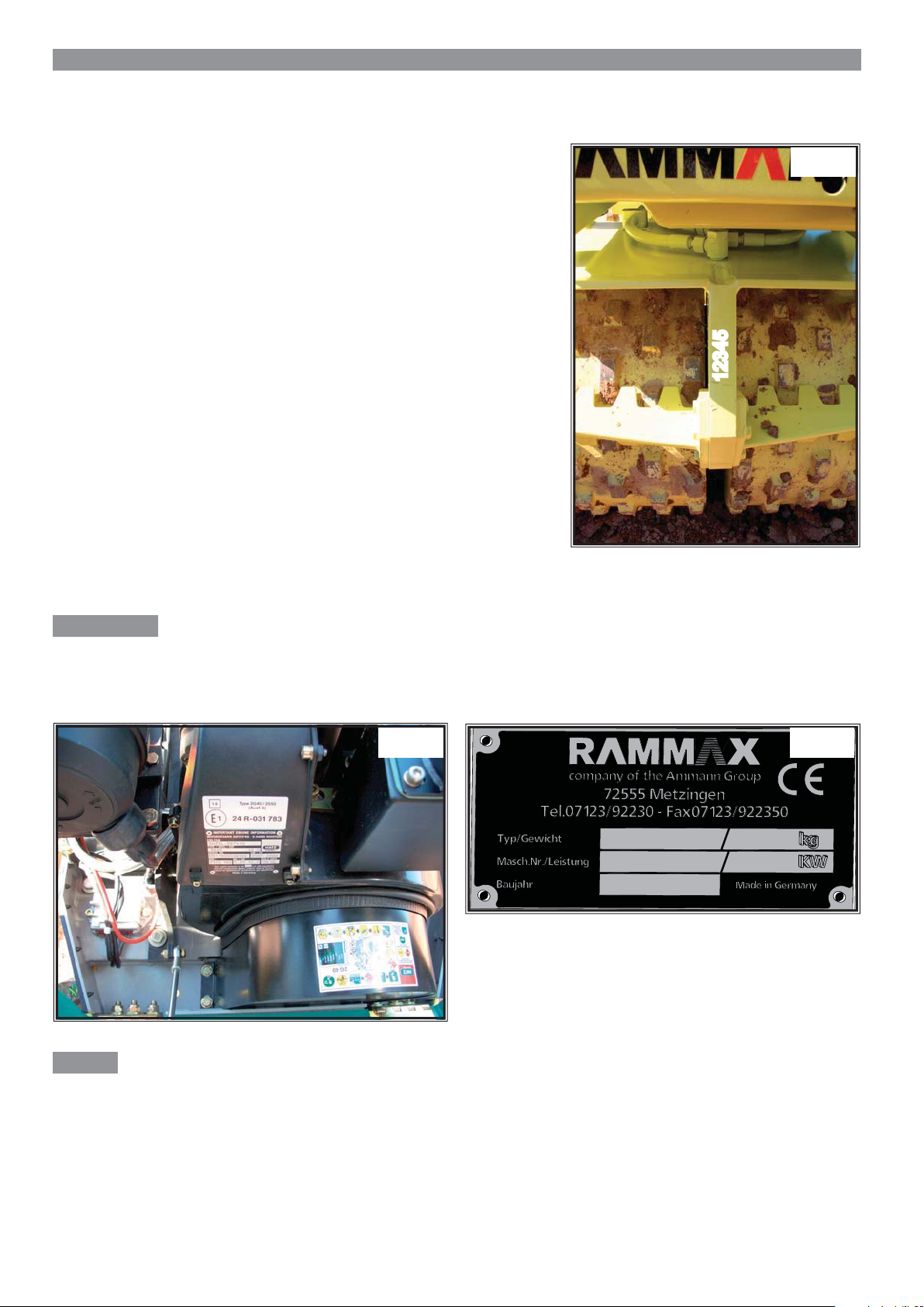
On transfer of the machine, please complete:
---------------------------------------------------------------Machine model (Fig. 3)
---------------------------------------------------------------Serial number (Fig. 1)
---------------------------------------------------------------Engine type
01
12345
---------------------------------------------------------------Engine number (Fig. 2)
Attention:
On machine acceptance, you will receive instruction in the operation and maintenance of the machine by one of our
staff or by an authorised dealer. It is vital that you pay particular attention to the instructions relating to safety aspects
and hazards which can arise at the machine.
0302
Note:
In the event that the engine number on the sticker is no longer legible due to soiling or damage, this number can also
be found on the engine block. The location of the embossed engine number on the engine block can be seen from the
Hatz operating and maintenance instructions.
4
4
Page 5

Table of Contents:
1.0 Specifi cations 7
1.1 Main dimensions . . . . . . . . . . . . . . . . . . . . . . . . . . . . . . . . . . . . . . . . . . . . . . . . . . . . . . . . . . . .9
1.2 Noise and vibration specifi cations . . . . . . . . . . . . . . . . . . . . . . . . . . . . . . . . . . . . . . . . . . . . .11
2.0 Description 12
2.1 Fields of application . . . . . . . . . . . . . . . . . . . . . . . . . . . . . . . . . . . . . . . . . . . . . . . . . . . . . . . .12
2.2 Modifi cations to the machine . . . . . . . . . . . . . . . . . . . . . . . . . . . . . . . . . . . . . . . . . . . . . . . . .12
3.0 Safety regulations 13
3.1 Intended use . . . . . . . . . . . . . . . . . . . . . . . . . . . . . . . . . . . . . . . . . . . . . . . . . . . . . . . . . . . . . .14
3.2 Operation of the machine . . . . . . . . . . . . . . . . . . . . . . . . . . . . . . . . . . . . . . . . . . . . . . . . . . . .14
3.3 Safety remarks in the operating and maintenance instructions . . . . . . . . . . . . . . . . . . . . . . .14
3.4 Safety signs attached to the machine . . . . . . . . . . . . . . . . . . . . . . . . . . . . . . . . . . . . . . . . . . .15
3.5 Loading the machine for transport . . . . . . . . . . . . . . . . . . . . . . . . . . . . . . . . . . . . . . . . . . . . .15
3.6 Starting the machine . . . . . . . . . . . . . . . . . . . . . . . . . . . . . . . . . . . . . . . . . . . . . . . . . . . . . . . .15
3.6.1 Before starting . . . . . . . . . . . . . . . . . . . . . . . . . . . . . . . . . . . . . . . . . . . . . . . . . . . . . . .15
3.6.2 Starting . . . . . . . . . . . . . . . . . . . . . . . . . . . . . . . . . . . . . . . . . . . . . . . . . . . . . . . . . . . .15
3.6.3 Jump starting with jump leads . . . . . . . . . . . . . . . . . . . . . . . . . . . . . . . . . . . . . . . . . . .15
3.6.4 Starting in enclosed areas. . . . . . . . . . . . . . . . . . . . . . . . . . . . . . . . . . . . . . . . . . . . . .16
3.7 Driving the machine . . . . . . . . . . . . . . . . . . . . . . . . . . . . . . . . . . . . . . . . . . . . . . . . . . . . . . . .16
3.7.1 Persons in the hazard area . . . . . . . . . . . . . . . . . . . . . . . . . . . . . . . . . . . . . . . . . . . . .16
3.7.2 Driving . . . . . . . . . . . . . . . . . . . . . . . . . . . . . . . . . . . . . . . . . . . . . . . . . . . . . . . . . . . . .16
3.7.3 Negotiating uphill and downhill slopes . . . . . . . . . . . . . . . . . . . . . . . . . . . . . . . . . . . .16
3.7.4 Driving in traffi c . . . . . . . . . . . . . . . . . . . . . . . . . . . . . . . . . . . . . . . . . . . . . . . . . . . . . .16
3.7.5 Checking the effects of vibration . . . . . . . . . . . . . . . . . . . . . . . . . . . . . . . . . . . . . . . . .16
3.7.6 Parking the machine . . . . . . . . . . . . . . . . . . . . . . . . . . . . . . . . . . . . . . . . . . . . . . . . . .16
3.7.7 Parking on uphill and downhill slopes . . . . . . . . . . . . . . . . . . . . . . . . . . . . . . . . . . . . .17
3.8 Refuelling . . . . . . . . . . . . . . . . . . . . . . . . . . . . . . . . . . . . . . . . . . . . . . . . . . . . . . . . . . . . . .17
3.9 Maintenance work . . . . . . . . . . . . . . . . . . . . . . . . . . . . . . . . . . . . . . . . . . . . . . . . . . . . . . . . .17
3.9.1 Work on hydraulic lines . . . . . . . . . . . . . . . . . . . . . . . . . . . . . . . . . . . . . . . . . . . . . . . .17
3.9.2 Changing hydraulic hoses . . . . . . . . . . . . . . . . . . . . . . . . . . . . . . . . . . . . . . . . . . . . . .17
3.9.3 Work on the engine . . . . . . . . . . . . . . . . . . . . . . . . . . . . . . . . . . . . . . . . . . . . . . . . . . .18
3.9.4 Work on parts of the electrical system . . . . . . . . . . . . . . . . . . . . . . . . . . . . . . . . . . . .18
3.9.5 Work on the battery . . . . . . . . . . . . . . . . . . . . . . . . . . . . . . . . . . . . . . . . . . . . . . . . . . .18
3.9.6 Work on the fuel system . . . . . . . . . . . . . . . . . . . . . . . . . . . . . . . . . . . . . . . . . . . . . . .18
3.9.7 Cleaning work . . . . . . . . . . . . . . . . . . . . . . . . . . . . . . . . . . . . . . . . . . . . . . . . . . . . . . .18
3.9.8 After completing maintenance work . . . . . . . . . . . . . . . . . . . . . . . . . . . . . . . . . . . . . .18
3.10 Repairs . . . . . . . . . . . . . . . . . . . . . . . . . . . . . . . . . . . . . . . . . . . . . . . . . . . . . . . . . . . . . .18
4.0 Display and operating elements 19
4.1 Description of the display and operating elements . . . . . . . . . . . . . . . . . . . . . . . . . . . . . . . . .20
4.2 Back-up safety bar . . . . . . . . . . . . . . . . . . . . . . . . . . . . . . . . . . . . . . . . . . . . . . . . . . . . . . . . .22
4.3 Engine safety support . . . . . . . . . . . . . . . . . . . . . . . . . . . . . . . . . . . . . . . . . . . . . . . . . . . . . . .22
4.4 Address setting . . . . . . . . . . . . . . . . . . . . . . . . . . . . . . . . . . . . . . . . . . . . . . . . . . . . . . . . . . . .22
55
Page 6

Table of Contents:
5.0 Operation with remote control 23
5.1 Precommissioning checks . . . . . . . . . . . . . . . . . . . . . . . . . . . . . . . . . . . . . . . . . . . . . . . . . . .23
5.2 Operation . . . . . . . . . . . . . . . . . . . . . . . . . . . . . . . . . . . . . . . . . . . . . . . . . . . . . . . . . . . . . .23
5.3 Starting the machine . . . . . . . . . . . . . . . . . . . . . . . . . . . . . . . . . . . . . . . . . . . . . . . . . . . . . . . .24
5.4 Switching on and reversing the direction of travel . . . . . . . . . . . . . . . . . . . . . . . . . . . . . . . . .25
5.5 Driving at high speed . . . . . . . . . . . . . . . . . . . . . . . . . . . . . . . . . . . . . . . . . . . . . . . . . . . . . . .25
5.6 Driving with vibration . . . . . . . . . . . . . . . . . . . . . . . . . . . . . . . . . . . . . . . . . . . . . . . . . . . . . . .25
5.7 Switching off the machine . . . . . . . . . . . . . . . . . . . . . . . . . . . . . . . . . . . . . . . . . . . . . . . . . . . .26
6.0 Manual control . . . . . . . . . . . . . . . . . . . . . . . . . . . . . . . . . . . . . . . . . . . . . . . . . . . . . . . . . . .26
6.1 Starting process . . . . . . . . . . . . . . . . . . . . . . . . . . . . . . . . . . . . . . . . . . . . . . . . . . . . . . . . . . .26
6.2 Driving operation . . . . . . . . . . . . . . . . . . . . . . . . . . . . . . . . . . . . . . . . . . . . . . . . . . . . . . . . . .26
6.3 High speed . . . . . . . . . . . . . . . . . . . . . . . . . . . . . . . . . . . . . . . . . . . . . . . . . . . . . . . . . . . . . .26
6.4 Vibration . . . . . . . . . . . . . . . . . . . . . . . . . . . . . . . . . . . . . . . . . . . . . . . . . . . . . . . . . . . . . .27
6.5 Switching off the machine . . . . . . . . . . . . . . . . . . . . . . . . . . . . . . . . . . . . . . . . . . . . . . . . . . . .27
7.0 Jump start device 28
8.0 Loading and transport 28
9.0 Maintenance 29
9.01 General remarks on maintenance and maintenance work . . . . . . . . . . . . . . . . . . . . . . . . . . .29
9.02 Running in regulations . . . . . . . . . . . . . . . . . . . . . . . . . . . . . . . . . . . . . . . . . . . . . . . . . . . . . .29
9.03 Maintenance schedule . . . . . . . . . . . . . . . . . . . . . . . . . . . . . . . . . . . . . . . . . . . . . . . . . . . . . .30
9.04 Checking the oil level in the engine . . . . . . . . . . . . . . . . . . . . . . . . . . . . . . . . . . . . . . . . . . . .31
9.05 Checking the hydraulic oil level . . . . . . . . . . . . . . . . . . . . . . . . . . . . . . . . . . . . . . . . . . . . . . .31
9.06 Checking the fuel level . . . . . . . . . . . . . . . . . . . . . . . . . . . . . . . . . . . . . . . . . . . . . . . . . . . . . .31
9.07 Changing the fuel fi lter . . . . . . . . . . . . . . . . . . . . . . . . . . . . . . . . . . . . . . . . . . . . . . . . . . . . . .32
9.08 Battery . . . . . . . . . . . . . . . . . . . . . . . . . . . . . . . . . . . . . . . . . . . . . . . . . . . . . . . . . . . . . .32
9.09 Changing the transmission oil . . . . . . . . . . . . . . . . . . . . . . . . . . . . . . . . . . . . . . . . . . . . . . . .33
9.10 Checking / cleaning / replacing the air fi lter . . . . . . . . . . . . . . . . . . . . . . . . . . . . . . . . . . . . . .33
9.11 Changing the engine oil . . . . . . . . . . . . . . . . . . . . . . . . . . . . . . . . . . . . . . . . . . . . . . . . . . . . .34
9.12 Changing the hydraulic oil . . . . . . . . . . . . . . . . . . . . . . . . . . . . . . . . . . . . . . . . . . . . . . . . . . .34
9.12.1 Hydraulic system . . . . . . . . . . . . . . . . . . . . . . . . . . . . . . . . . . . . . . . . . . . . . . . . . . . . .34
9.12.2 Hydraulic oil change . . . . . . . . . . . . . . . . . . . . . . . . . . . . . . . . . . . . . . . . . . . . . . . . . .35
9.13 High-pressure line fi lter . . . . . . . . . . . . . . . . . . . . . . . . . . . . . . . . . . . . . . . . . . . . . . . . . . . . . .35
9.14 Changing the suction fi lter . . . . . . . . . . . . . . . . . . . . . . . . . . . . . . . . . . . . . . . . . . . . . . . . . . .36
9.15 Adjusting the stripper . . . . . . . . . . . . . . . . . . . . . . . . . . . . . . . . . . . . . . . . . . . . . . . . . . . . . . .36
10.0 Tightening torques for bolts with standard metric thread 37
11.0 Troubleshooting table 38
66
Page 7
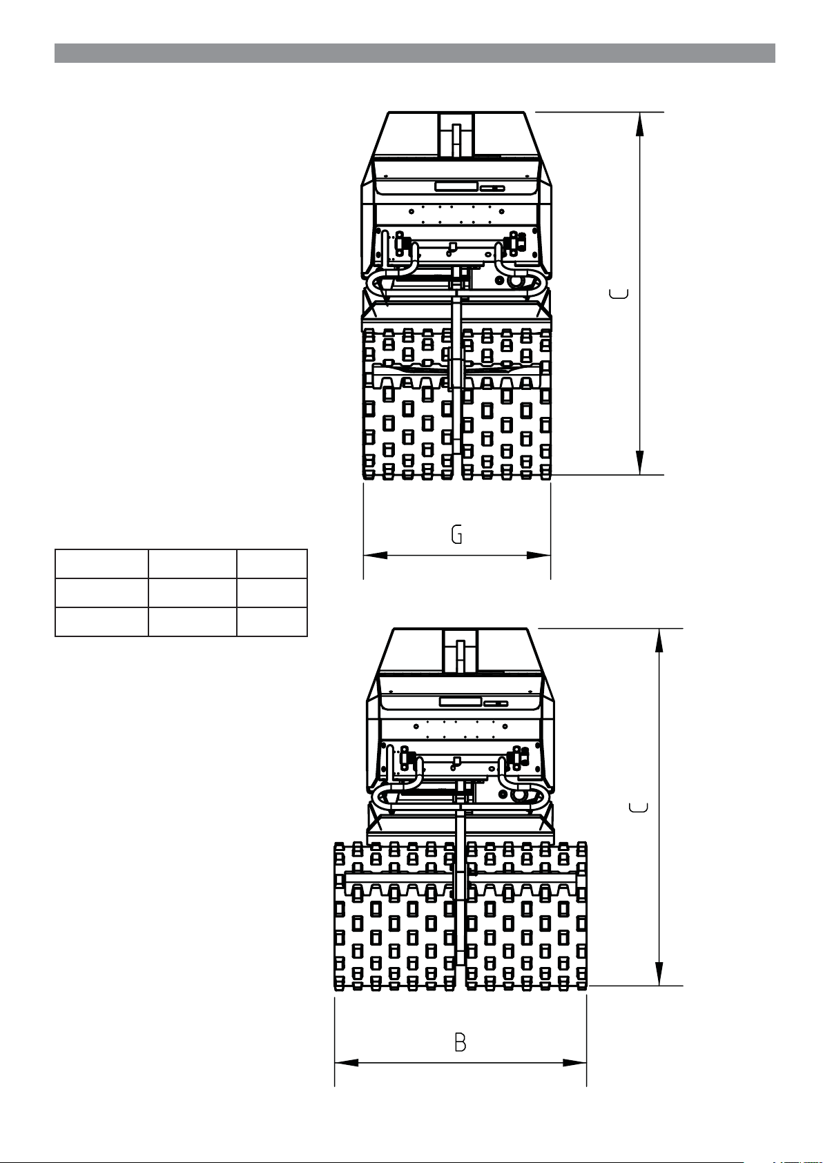
Specifi cations:
B: 850 mm
C: 1200 mm
G: 630 mm
7
7
Page 8
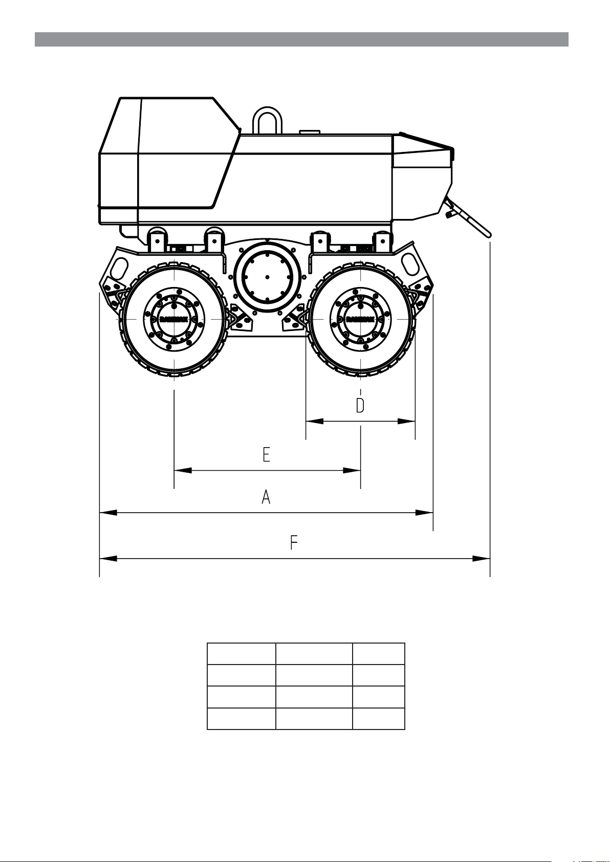
Specifi cations:
A: 1520 mm
D: 500 mm
E: 855 mm
F: 1780 mm
8
8
Page 9

1.1 Main dimensions
Specifications:
RW 1504 /HF/HK/FK/HFK
Working width: mm 850 630
Overall width mm 850 630
Overall length mm 1770 1770
Overall height mm 1200 1200
Distance between axles mm 850 850
Drum diameter mm 500 500
Weights:
Intrinsic weight: kg 1413 1341
Operational weight: kg 1480 1408
Mean axle load: kg 740 704
Drive system:
Engine/Type: Hatz 2G40 Hatz 2G40
Output: kW/PS 13.2 / 18 13.2 / 18
At rpm: 2700 2700
No. of cylinders/cooling: 2 / air cooled 2 / air cooled
Battery: V 12 12
Ah 72 72
Drive mode: hydrostatic hydrostatic
Driven drums: 4 4
Drum width 850 mm Drum width 630 mm
Vibration system:
Centrifugal
force:
Amplitude: Vibration forwards: mm
Frequency: Vibration forwards: Hz
Drive mode: hydrostatic hydrostatic
Vibrating drums: 4 4
Brakes:
Service brake: hydrostatic hydrostatic
Parking brake: hydromechanical hydromechanical
Vibration forwards: kN
Vibration reverse: kN
Vibration reverse: mm
Vibration reverse: Hz
82 82
2,2 2,2
30 30
99
Page 10

Specifications:
RW 1504 /HF/HK/FK/HFK
Steering:
Steering mode: lever steering lever steering
Steering actuation: hydrostatic hydrostatic
Filling capacities:
Fuel: I 25 25
Hydraulic oil: I 47 47
Transmission oil (per drive): l 1.1 1.1
Driving characteristics:
Speed (forwards/reverses):
With vibration: m/min 0-16 0-16
Without vibration: m/min 0-16 0-16
High speed: m/min 0-35 0-35
Maximum climbing ability:
With vibration: % 45 45
Without vibration: % 55 55
Special equipment:
Drums: Standard profi le Cam height 15 mm Cam height 15 mm
Drums: Special profi le Cam height 18 mm Cam height 18 mm
Drum width 850 mm Drum width 630 mm
1010
Page 11

Specifi cations:
1.2 Noise and vibration specifi cations
The noise and vibration specifi cations listed below in accordance with the EC Machine Directive in the draft
(93/68/EEC) were determined under operating conditions typical for the machinery in question with vibration
over a specifi ed travel surface (DIN 45635).
In operational application, deviating values may result depending on the prevailing operating conditions.
Noise specifi cation
The noise emission specifi cation stipulated in accordance with Annex 1, Section 1.7.4.f of the EC
Machine Directive is as follows:
- Sound pressure level at the operator position: LpA = 86.9 dB(A)
- Sound power level: LWA = 102.7 dB(A)
These noise emission values were determined in accordance with ISO 6081 for the sound pressure
level (LpA) and ISO 3744, DIN 45635, for the sound power level (LWA).
Vibration specifi cation
The vibration specifi cations stipulated in accordance with Annex 1, Section 2.2 / 3.6.3. a of the EC
Machine Directive are as follows:
Hand-arm vibration values
The weighted effective acceleration value, determined in accordance with ISO 8662 Part 1, DIN
45675, Part 9, is approx. 10.3 m/sec˛.
Technical modifi cations reserved
Rammax RW 1504
1111
Page 12

Description:
2.0 Description
Many years of experience in the development and design of vibratory trench rollers created the basis for the new
development of the infrared-controlled model RW 1504-HF.
The enormous degree of operating convenience, which provides both for manual and infrared control, permits the
user to make even more fl exible use of the machine.
The hard-wearing, compact design offers a high degree of security even in the most diffi cult terrain.
Using the remote control facility, it is possible to control, start and switch off the machine up to 15 metres away
from the operator.
Steering, vibration and travel drive in the RW 1504-HF are performed hydrostatically. The machine is enormously
maintenance friendly (with the exception of the diesel engine). There are no V-belts, toothed belts, lubricating nipples
or clutches with shift facility. This modern vibratory trench roller features offers easy access to the servicing points at
the diesel engine, one-handed operation and sound absorption, 8 strippers and an operating hourmeter.
2.1 Fields of application
The vibratory trench roller RW 1504-HF is designed especially for trench compaction work. The complete
lateral clearance of the drums guarantees compaction right up to the trench wall even in extremely tight
and narrow trenches. The fi elds of application for this modern vibratory roller include wet, clay soil of the
type encountered in canal building, pipe-laying, road substructure work and backfi ll work.
The infrared control facility also permits passage through trench sheeting and bracing, and underneath
cross struts. In case of hazardous site missions, it is possible for the operator to control the machine from a
safe distance and thus avoid exposure to personal danger.
2.2 Modifications to the machine
For reasons of safety, users are prohibited from making their own modifi cations or conversions to the
machine.
This machine must only be equipped using original spare parts designed for use with the machine and in compliance
with the requirements of the manufacturer. The installation or utilisation of special equipment or special parts can
impair driving safety.
The manufacturer will accept no liability for damage caused as a result of the use of non-original parts or special
equipment.
1212
Page 13

Safety regulations
1313
Page 14

Safety regulations:
3.1 Intended use
Vibratory trench roller RW 1504-HF is constructed in accordance with the state of the art and with accepted rules of
operating safety. However, its use can still give rise to hazardous situations which constitute a danger to life and limb
for the operator or for third parties or which can lead to impairment of the machine or damage to other property if:
• It is used in a manner other than its intended use
• It is modifi ed or conversion work is carried out by unqualifi ed persons
• The safety remarks are not observed
• It is not operated or maintained by suitably qualifi ed personnel.
The RW 1504-HF must only be operated when in a technically fl awless condition and in accordance with its
intended use with suffi cient awareness of safety aspects and potential hazards and in strict observance of the
operating instructions. In particular malfunctions which could detract from the safety of the equipment must be
remedied without delay.
When operating the roller, adherence to the valid accident prevention regulations and the generally accepted rules of
safety, as well as country-specifi c regulations is assumed.
The point „Fields of application“ (Section 2.1) outlines the designated purpose for which the RW 1504-HF is
exclusively intended. Any other or further reaching use is deemed to be not in accordance with its intended use. The
manufacturer/supplier accepts no liability for any damage arising as a result of such incorrect use. All risk arising rests
solely with the user.
3.2 Operation of the machine
Only suitably qualifi ed and designated persons who have received the appropriate training, and who are over 18
may drive and operate the machine. Fields of responsibility during operation must be clearly defi ned and observed.
All persons entrusted with operation, maintenance or repair of the machine must read and adhere to the safety
regulations. Where appropriate, this must be confi rmed by the user‘s company by means of a signature by the person
or persons concerned.
Persons acting under the infl uence of drugs, medicines or alcohol may not operate, maintain or repair the
machine.
Maintenance and repair require specialist knowledge and may only be carried out by qualifi ed specialist personnel.
3.3 Safety remarks in the operating and maintenance instructions
i Danger
This warning sign is an indication of possible danger of personal injury.
Note:
This warning sign is an indication of possible impairment to the machine or parts of the equipment.
Remark:
These parts of the instructions provide technical information intended to ensure optimum economy and effi cient use of
the machine.
1414
Page 15

Safety regulations:
3.4 Safety signs attached to the machine
Keep all safety plates and labels in good legible order and ensure their observance. Damaged and illegible safety
plates and labels must be renewed without delay. All plates and labels can be re-ordered from the spare parts list.
3.5 Loading the machine for transport
• Only use stable loading ramps with suffi cient load-bearing capacity. The ramp incline must not be any steeper than
the specifi ed climbing ability (see Specifi cations) of the machine.
• Safeguard the machine against tilting or slipping.
• Safeguard the machine on transport vehicles against rolling, slipping and tipping over.
• When raised, the machine must not be allowed to swing wildly.
The following situations represent a danger to life and limb:
• Walking or standing under suspended loads.
• Remaining within the driving area of the machine while it is being guided into position and loaded.
3.6 Starting the machine
3.6.1 Before starting
• The machine may only be operated from the operator‘s side (behind the machine).
• Familiarise yourself with the equipment, the operating and control elements and the functional characteristics of the
machine.
• Use personal safety gear (safety helmet, safety shoes, ear protection etc.).
Before starting, check whether:
• There are persons or impediments located next to or under the machine
• The machine is free of oily and fl ammable materials
• All handles, steps and platforms are free of grease, oil, fuels, dirt, snow and ice
• The machine exhibits any obvious defects
• All protective gear is securely in place
• Brakes and operating elements are working
Never start the machine if any instruments, pilot lamps or control organs are defective.
Do not tie any loose objects onto the machine.
3.6.2 Starting
For starting, all operating levers must be in the „Neutral position“.
After starting, check all display and operating elements.
3.6.3 Jump starting with jump leads
Note:
The machine is equipped with a 12-Volt system!
Connect the plus to the plus terminal and the minus to the minus terminal (earth cable). Connect the earth
cable last and disconnect fi rst! Incorrect connection will result in serious damage to the machine‘s electrical
system.
1515
Page 16

Safety regulations:
3.6.4 Starting in enclosed areas
Exhaust fumes are lethal!
When starting in closed rooms, therefore, always ensure suffi cient ventilation.
3.7 Driving the machine
3.7.1 Persons in the hazard area
Each time before starting work, also after interruptions, check whether there are persons or obstacles positioned in
the hazard area, particularly when reversing. If required, give a warning signal. Stop work immediately if persons fail
to leave the hazard area despite warning.
3.7.2 Driving
• In emergency situations and in case of danger, stop the machine immediately. Only resume operation when the
danger which caused the stop has been eliminated.
• The machine may not be used to transport persons.
• In case of unusual noises and generation of smoke, ascertain the cause and have the problem remedied.
3.7.3 Negotiating uphill and downhill slopes
• Do not drive up or down slopes steeper than the maximum climbing ability of the machine.
• On slopes, always drive directly upwards or downwards and proceed with caution. Before starting, select a lower
gear.
• Damp and loose substrates substantially reduce the machine‘s grip on sloping surfaces and inclines. Increased risk
of accidents!
3.7.4 Driving in traffi c
• Adjust your speed to the working conditions.
• Always give way to loaded transport vehicles.
• Keep your distance from edges and embankments.
3.7.5 Checking the effects of vibration
During compaction work with vibration, check the effect on adjacent buildings and buried pipelines (gas, water,
sewage, electrical). If necessary, compaction work may have to be discontinued.
Never use vibration on hard substrates (concrete or frozen earth), as this will damage the bearings!
3.7.6 Parking the machine
Wherever possible, park the machine on a fi rm, even surface.
Before leaving the machine:
• Switch off the engine and pull out the ignition key.
• Parked machines which could represent an obstruction must be safeguarded by clearly identifi able measures.
1616
Page 17

Safety regulations:
3.7.7 Parking on uphill and downhill slopes
Safeguard the machine against rolling away. To do this use metal chocks in front of and behind the drums.
3.8 Refuelling
• Never breathe in fuel fumes.
• Only refuel when the engine is switched off.
• Never refuel in enclosed areas.
• No naked fl ames, no smoking.
• Do not spill fuel, mop up any splashes of fuel, do not allow to seep into the ground.
3.9 Maintenance work
• Maintenance work may only be performed by suitably qualifi ed and trained personnel.
• Keep unauthorised persons away from the machine.
• Never carry out maintenance work on a moving machine or with the engine running.
• Wherever possible, park the machine on a fi rm and even surface.
• Remove the key from the ignition switch.
3.9.1 Work on hydraulic lines
Before performing any work on hydraulic systems, they must be depressurised. Hydraulic oil emerging under pressure
can penetrate the skin and cause serious injury. In case of injury due to oil emerging at high pressure, immediately
consult a doctor as serious infections can result. When performing adjustment work on the hydraulic system, do not
stand in front of or behind the drums. Do not adjust the pressure relief valves.
Drain off the hydraulic oil at operating temperature – danger of scalding! Collect drained hydraulic oil and dispose of
in an environmentally responsible manner. Never attempt to start the engine when the hydraulic oil has been drained.
After the completion of all work (with the system still depressurised!), check the seal of all connections and
screw joints.
3.9.2 Changing hydraulic hoses
Hose lines must never be swapped or exchanged. Subject hydraulic hose lines to regular visual inspections. The
immediate exchange of hydraulic hose lines is essential in the following cases:
• Damage of the outer ply through to the inlay (e.g. abrasion, cuts).
• Brittleness of the outer ply (crack formation in the hose material).
• Deformation in pressureless or pressurised condition which does not correspond with the original shape of the
hydraulic hose line.
• Deformation on bending, e.g. crushing points, kinks, separation of plies, formation of blisters.
• Incorrectly executed installation.
• Migration of the hydraulic hose from the fi tting.
• Corrosion of the fi tting which impairs functional characteristics and strength.
• Damage or deformation of the fi tting which impairs functional characteristics, strength or the hose to hose
connection.
Only original RAMMAX spare hydraulic hose lines offer the security of using the correct hose type (pressure stage) in
the right situation.
1717
Page 18

Safety regulations:
3.9.3 Work on the engine
Drain the engine oil at operating temperature – Danger of scalding!
Wipe away any spilt oil, collect drained oil and dispose of in an environmentally responsible manner. Keep used
fi lters and other oil-soiled materials in a separate, specially marked container and dispose of in an environmentally
responsible manner.
3.9.4 Work on parts of the electrical system
• Before performing work on the electrical system, disconnect the battery and cover with isolating material.
• Do not use fuses with a higher amperage or repair fuses. Fire hazard!
3.9.5 Work on the battery
• When carrying out work at the battery, never smoke or expose to a naked fl ame.
• Do not allow acid to contact hands or clothing. In case of injury due to acid spillage, rinse with clear water and
consult a doctor.
• Never place any tools on the battery.
• Dispose of old batteries in compliance with regulations.
3.9.6 Work on the fuel system
• No naked fl ames, no smoking, do not spill fuel.
• Collect emerging fuel, do not allow to seep into the ground and dispose of in an environmentally friendly manner.
3.9.7 Cleaning work
• Never carry out cleaning work with the engine running.
• Never use petrol or other easily fl ammable materials for cleaning.
• When cleaning using a steam jet cleaning device, cover all electrical parts and the insulating material or do not
expose to direct water or steam jet.
• Do not direct the cleaning jet into the silencer.
3.9.8 After completing maintenance work
• All protective devices must be replaced after cleaning and maintenance work.
• Carry out function checks.
3.10 Repairs
If the machine is defective, hang a warning sign on the machine. Repairs may only be performed by qualifi ed and
specially commissioned personnel.
1818
Page 19

Display and operating elements:
4.0 Display and operating elements
Cockpit:
LKZ
04
Z: Ignition lock
LK: Battery charge indicator light
NG: Inclination indicator
ÖK: Oil pressure warning light
SZ: Hourmeter
ÖK
NG
SZ
Transmitter:
FR
E N S
FL: Travel, left
FR: Travel, right
V: Vibration
E: High speed
S: Start/stop
N: Emergency stop
FRV
05
06
V
FL
FRE
GH
GH: Throttle lever
07
19
19
Page 20

Display and operating elements:
4.1 Description of the display and operating elements
LK: Battery charge indicator light
Lights up: • When the ignition is switched on
• In case of charging faults in operation, ascertain cause
Goes out: • After starting the engine.
ÖK: Oil pressure warning light
Lights up: • When the ignition is switched on
• In the event of a drop in oil pressure in operation.
Goes out: • After starting the engine.
NG: Inclination indicator
Lights up: • When the ignition is switched on
• In the event of a drop in oil pressure in operation.
Goes out: • After starting the engine.
GH: Throttle lever
Position „0“: • Switches off the engine
Position „I“: • Starts the engine
• Operating position for vibration
Z: Ignition switch
Position „0“: • Inserting and removing the key.
Position „I“: • Ignition on, battery charge indicator light „LK“ and oil
pressure warning light „ÖK“ light up.
Position „II“: • Turn the ignition key further against spring pressure
towards position II
Engine starts up. After engine start, release key, pilot
lamps go out.
0
I
0
I
II
Remark:
The ignition switch has a start repeat disable function. To restart the engine, fi rst turn the key to the „0“ position.
Continue to start without interruption for max. 15 to 20 seconds, with pauses of approx. one minute between. If the
engine fails to start within this time, ascertain the cause of the fault and remedy. The engine can only be started with
the throttle lever in the middle position.
20
20
Page 21

Display and operating elements:
SZ: Hourmeter
The hourmeter counts the number of operation hours with the ignition switched on. The maintenance work must be
carried out according to the displayed operating hours.
FR: Travel lever for drums, right
Position „0“ = Zero position for engine start
Position „Front“ = Forward travel!
Position „Back“ = Reverse travel!
FL: Travel lever for drums, left
Position „0“ = Zero position for engine start
Position „Front“ = Forward travel!
Position „Back“ = Reverse travel!
Remark:
The position of the two travel levers FR and FL relative to one another determines the direction of travel: straight on,
left-hand curve, right-hand curve or turning around the vertical axis (rotating on the spot, see diagram).
08 09
21
21
Page 22

Operation:
4.2 Back-up safety bar
Forward travel: No function!
Reverse travel: If the back-up safety bar is actuated,
the machine automatically comes to an
immediate stop.
Moving clear: Move Both travel levers „FR“ and
„FL“ to the „front“ position, the
machine travels away from the
obstacle!
4.3 Engine safety support
Used for fi lling the fuel tank or when the engine hood
is opened to carry out repairs. The hood is safeguarded
against dropping by the gas pressure spring.
i Danger
The engine hood falling down can lead to serious
injury!
The gas compression spring must not be removed
and must always replaced in order to exclude the
danger of injury..
10
11
4.4 Address setting
• Open cover D.
• Loosen plug „S-A“ on the transmitter and receiver.
(Fig. 13-15)
• Using a screwdriver, it is then possible to set
up to four addresses.
Note:
• The addresses at the transmitter and receiver
must correspond.
• Example: 0 - 0/9 - 9 etc.
22
22
14
1312
15
Page 23

Operation:
5.0 Operation with remote control
5.1 Precommissioning checks
Before putting the machine into service every day or before a long work period, the following checks must be
performed.
i Danger
Observe the safety remarks in section 3.0 of this operating and maintenance manual.
• Place the machine on an even, load-bearing surface.
Check:
• All screw joints
• Function of the travel levers
• Function of the back-up safety bar
• The machine for any damage
• The emergency stop switch of the transmitter
Remark:
The following checks are described in the section „9.0 Maintenance“!
• Engine oil level
• Hydraulic oil level
• Fuel level
5.2 Operation
When operating the machine with remote control, the correct position is behind the roller. Zone „A“. If the operator is
standing on the other side - Zone „B“ - the actuating directions of the control elements do
not correspond to those of the roller.
Zone B Zone A
When operating the machine with the remote control, the minimum distance from the machine must be 2 metres, as
under some operating conditions refl ections occur which can cause errors in the close range
stop function.
2323
Page 24

Operation:
Note:
• Desist from any method of operation which could pose a safety hazard or impair the static stability of the
machine.
• Never travel on sloping surfaces transversely, but always directly upwards or downwards.
• Every time before starting up, always clean the transmitter and receiver elements.
• For safety reasons, never deposit the transmitter near the machine. During breaks in work, the emergency
stop switch must always be activated (Position „0“).
Should the transmitter be defective for any reason, switch off the machine immediately using the throttle lever „GH“.
i Danger
Before driving, check whether persons are located in the driving area. Damp and loose substrates substantially
reduce the machine‘s grip on sloping
surface and inclines. When driving up slopes and inclines, the speed must be adjusted in line with the terrain. Never
drive at high speed on slopes and inclines.
Remark:
The transmitter is fi tted with solar cells:
• Steps must be taken to guarantee that the solar cells are not covered during and after operation, in order to
guarantee automatic charging..
• The solar cells must also be cleared of dirt, as otherwise automatic charging cannot be guaranteed.
5.3 Starting the engine
When starting the engine, the starting conditions of the engine manufacturer must be observed.
1. Fill with fuel (see Maintenance section 9.6)
2. Move the throttle lever to the „Start“ position (Fig. 17).
3. All switching levers must be in the neutral position (Fig. 18).
4. Slip on the transmitter, move the emergency stop switch from the „N“ to the
„I“ position (Fig. 19).
5. Press the Start/Stop switch „S“ (Fig. 16) to the left and hold until the engine
starts.
17
18
16
19
Remark:
• Do not actuate the start switch for longer than 15 secs. If the engine fails to start repeat the process.
• For starting with jump leads, see section 7.0, page 28.
24
24
Page 25

Operation:
Note:
• The minimum distance between the transmitter (operator) and the receiver (machine) is 2 metres. If the
the minimum distance is not adhered to, the safety close-range function is activated, i.e. the machine
cannot be started.
• If the minimum distance is not adhered to during operation, the engine continues to run but the machine
comes to a standstill. In both cases, increase the distance and repeat the process.
• If several machines are in use at the same location, the addresses must be coordinated.
i Danger
Switching errors or malfunctions can be caused as a result of identical frequencies!!!
5.4 Switching on and reversing the direction of travel
• Travel levers „FL“ and „FR“ in „front“ position: Machine travels forwards.
• Travel levers „FL“ and „FR“ in „back“ position: Machine travels backwards.
• If the travel levers are moved in opposite directions, the machine travels around its vertical axis (on the spot).
• The machine comes to a stop when the travel levers are not actuated.
5.5 Driving at high speed
20
• Driving at high speed is only possible if the switching lever
„E“ is pushed forwards. (Fig. 20)
• Operate both travel levers „FL“ and „FR“ as for normal
operation.
Note:
The roller travels at twice the speed in the „high speed“ mode.
5.6 Driving with vibration
• Vibration is switched on when the switching lever „V“ is pressed forwards or back (Fig. 21).
• If the switching lever is pushed forwards, the vibration runs „forwards“, if the lever is pushed back, it
runs „in reverse“.
• In even terrain, the switch position is of no consequence.
• However, if the machine has to negotiate an incline, the vibration be switched to the direction of travel in
order to increase the machine‘s climbing ability.
E
21
25
25
Page 26

Operation:
5.7 Switching off the machine
1. Move the switches „FL“, „FR“, „V“ and „E“ to their central position / switch off (Fig. 22).
2. Press the Start/Stop switch „S“ to the right and hold there until the engine comes to a complete standstill.
3. Actuate the emergency stop switch „N“ by pressing down. (Fig. 22)
FL FRV
E SN
22
Note:
After switching off the machine, the ignition key must be removed.
6.0 Manual control
Note:
All safety conditions from Section 5.0 Operation with remote control must be observed when working with manual
control!
6.1 Starting process
When starting the engine, the starting conditions of the engine manufacturer must be observed.
1. Fill with fuel (see Maintenance section 9.06)
2. Move the throttle lever to position „I“ (Fig. 17).
3. All switching levers must be in the neutral position (Fig. 18).
4. Turn the ignition switch to the position „I“ (Fig. 24). Oil pressure warning light „ÖK“ and battery charge indicator light
„LK“ light up.
6.2 Travel operation
Push both travel levers „SL“ and „SR“ to the front.
The machine begins to travel forwards. For reverse travel, pull both travel levers backwards.
To steer to the side, the travel levers are moved in the opposite directions (turning on the spot).
6.3 High speed
Push the switch lever „SE“ forwards. The functional is the same as for the work mode..
Note:
The machine travels twice as fast in „high speed“ mode as in the working mode!
26
26
Page 27

Operation:
6.4 Vibration
When travelling with vibration, in addition to travel levers „SL“ and „SR“,
the switching lever „SV“ is actuated (Fig. 23). In the central position, vibration is switched off, in position „V“ forwards
or „R“ reverse.
Remark:
When working on even terrain, the switch position of the vibration lever „ V „ or „ R „ is not important.
However, if the machine has to negotiate an incline, the vibration switching lever must be switched to the
direction of travel in order to increase the machine‘s climbing ability.
23
V
R
6.5 Switching off the machine
1. Move the switches „FL“, „FR“, „V“ and „E“ to their middle / off position (Fig. 25).
2. Move the throttle lever „GH“ to position „0“ (Fig. 24).
3. Turn the ignition switch to position „0“ (Fig. 26).
24
25
26
Note:
After switching off the machine, the ignition key must be removed.
0
I
II
27
27
Page 28

Operation:
7.0 Jump start device (FSE)
Note:
12 V system!!!
1. Connect the jump start battery to the „+“ terminal and
the „+“ terminal of the FSE to the machine.
2. Connect the jump start battery to the „-“ terminal and
the „-“ terminal of the FSE to the machine.
3. Start the machine (page 26, section 6.1) Start
procedure
4. Disconnect the battery again in the reverse order.
27
Remark:
In order to avoid danger when connecting and
disconnecting the battery,
connect the „+“ terminal fi rst and disconnect it last. The „-“
terminal should never be connected alone.
8.0 Loading and transport
• To load the roller using hoisting gear, there is a central transport eye bolt „B“ in the middle of the roller (Fig. 28).
• The roller can also be loaded independently by being driven up a suitable loading ramp.
28
O O
Note:
• Only loading ramps with suffi cient loading capacity and static stability must be used which exclude any possibility of
personal injury.
• To lash the roller, always use shackles which are fastened to the transportation eye bolts „O“ (at the front and back
of the central web).
• The roller must be lashed in such a way that it is secured against tipping over, slipping or rolling away.
• Do not walk or stand under suspended loads.
28
28
Page 29

Maintenance:
9.0 Maintenance
9.01 General remarks on maintenance and maintenance work
Steps must be taken to ensure that all safety regulations are adhered to in the execution of
maintenance work!
Careful machine maintenance guarantees far greater functional reliability and increases the life of all
important components. The necessary input is minimal in relation to the faults and problems which can
occur as a result of failure to perform maintenance work.
• The engine and machine must be thoroughly cleaned before performing any maintenance work.
• Maintenance work may only be performed when the engine is at a standstill.
• When working with the hydraulic system, this must fi rst be depressurised.
• Before working on the electrical system, detach the battery, cover it and protect with insulating material.
• Check the electrical equipment of the machine at regular intervals. Defects such as loose connections or
melted cables must be remedied immediately and replaced by new ones.
• Only carry out maintenance and repair work when the machine is positioned on an even surface capable
of bearing loads and safeguarded against rolling away.
• Adhere to the prescribed maintenance and inspection procedures in the operating instructions, including
instructions in the exchange of parts. This work may only be performed by specialised personnel.
• Oil and fuels must not be permitted to seep into the ground or sewage system during maintenance work.
These must be collected using suitable means and disposed of in an environmentally responsible
manner!
Remarks on the hydraulic system:
Avoid dirt or other contaminants entering the hydraulic system. Even the smallest dirt particles in the
hydraulic pipework can lead to tremendous impairment to hydraulic units and so to costly repairs.
• Should it be discovered during the daily check of the hydraulic oil level that the oil level is sinking,
the complete hydraulic pipework must be checked immediately for leaks.
• Leaks must be repaired immediately. If necessary, inform the responsible after-sales service.
• If possible fi ll the hydraulic system with fi lling aggregate.
• Clean screw joints, the fi lling cap and its surroundings before removal to prevent the ingress of
dirt particles.
• Do not leave the tank cap open unnecessarily to prevent foreign bodies entering the system.
9.02 Running in regulations
Maintenance after 25 hours of operation:
• Check all screw connections and tighten if necessary.
• Check hydraulic hoses and the complete hydraulic oil system for leaks.
• Replace the fuel fi lter. (Fig. 18, section 9.7)
• Engine : See maintenance instructions Hatz 2G40!
2929
Page 30

Maintenance:
9.03 Maintenance schedule
No.: Description: Remarks: Page:
Every day
8.6 • Check engine oil level • Observe gauge marking 35
8.7 • Check hydraulic oil level • Oil sight glass 35
• Check hydraulic fi lter element
8.8 • Check fuel level • Sight glass 36
8.12 • Check air fi lter 38
• Diesel engine, see Hatz 2G40 operating manual (Annex)
After 25 hours of operation
• Check all bolts and screws for tightness Tightening torques
8.9 • Replace fuel fi lter 36
• Diesel engine, see Hatz 2G40 operating manual (Annex)
• Replace high-pressure fi lter element
After 75 hours of operation
8.15 • Replace air fi lter cartridge (earlier, if necessary) 40
8.10 • Service the battery Grease the terminals 37
• Note: Diesel engine oil (see Hatz 2G40 operating manual) (see Annex)
Every 100 operating hours
8.12 • Clean or replace air fi lter cartridge (earlier, if necessary) 38
9.0 • Service the battery 43
Every 250 operating hours
• Check the oil level in the travel drives
8.11 • Check all bolts and screws for tightness Tightening torques 41
8.9 • Drain water from diesel line fi lter or replace fi lter 36
8.9 • Inspect all diesel lines for leaks 36
Every 500 operating hours
8.15 • Diesel engine, see Hatz 2G40 operating manual (see Annex) 40
• Change the transmission oil in the travel drives (at least every 6 months)
• Replace high-pressure fi lter element (2nd service)
Every 1000 operating hours
8.14.2 • Change the hydraulic oil (at least 1x per year) 40
• Replace high-pressure fi lter element
8.9 • Replace fuel fi lter (after the 3rd service, at least
1x per year)
8.15 • Replace suction fi lter 40
36
As required
8.16 • Adjust stripper 41
8.11 • Check all bolts and screws for tightness Tightening torques 41
• Engine conservation see Hatz 2G40 operating
manual (Annex)
3030
Page 31

9.04 Check engine oil level
Remark:
Park the machine on an even, load-bearing surface in such a way that it is horizontal.
• Pull out the oil dip stick „MS“ and wipe off with a lint-free cloth (Fig. 29).
• Insert the oil dip stick as far as it will go and pull out again.
• The oil level must be between the two marks.
• If the oil level is below the bottom mark, top up with oil immediately.
For suitable oil types, see the Hatz 2G40 manual!
9.05 Checking the hydraulic oil level
Remark:
Park the machine on an even, load-bearing surface in such a way that it is horizontal.
Maintenance:
29
E
• Check the hydraulic oil level at the oil sight glass under the engine hood.
• Only check the oil level when the engine is cold. The hydraulic oil should come up to the middle of the sight glass.
• If necessary, top up with hydraulic oil.
Recommended oil types: Mobil HPL 46, Texaco Rando HD-C. Equivalent oil types from
other manufacturers can be used.
Remark:
If it is discovered during the daily oil level check that there is hydraulic oil missing, Check all units, pipelines and
houses immediately for leaks.
9.06 Checking the fuel level
i Danger
Danger of fi re!
When working with the fuel system, no naked fl ames,
no smoking. Do not refuel in enclosed areas. Do not breathe in fuel fumes.
Note:
Contaminated fuel can lead to the failure of or damage to the engine.
If necessary, top up fuel through a sieve fi lter.
Clean the area surrounding the fi lling hole and refuel.
Fuel: See the Hatz 2G40 operating manual!
(Annex)
30
31
31
Page 32

Maintenance:
9.07 Changing the fuel fi lter
Note:
When working on the fuel system, no naked fl ames, no smoking.
• The diesel line fi lter „DF“ must be drained of water at least once a year or every
200 hours (Fig. 31).
• To drain off the fi lter, the handwheel must be opened, until surplus water runs
away and pure diesel fuel emerges.
• After draining, close the hand wheel and check the fi lter for leaks.
Changing the fuel fi lter
• Release both fi llister-head screws at the fi lter holder and remove the fuel fi lter
„DF“ (Fig. 31).
• Detach the fuel hoses and insert new fuel fi lter „DF“. Replace any fuel hoses that
are porous or leaking.
• Mount the fuel fi lter „DF“ in reverse order and check for leaks.
• The fuel system is self-priming.
Note:
Collect any emerging fuel and dispose of in an environmentally responsible
manner together with the fuel fi lter!
31
9.08 Battery
i Danger
When working with the battery, no naked fl ame, no smoking! Do not allow acid to come into contact with clothes or skin!
Wear protective goggles! Do not lay any tools on the battery!
The battery is located under the hood (Fig. 32). It is very important to keep the battery clean and to carry out
maintenance correctly in order to have a perfect function of this battery. If the machine is out of action for a longer
period of time the battery must be disconnected in order to prevent a deep discharge. Especially the terminals and
clamps must be cleaned regularly and afterwards be coated thickly with an acidproof grease.
Note:
Dispose of old batteries correctly.
32
32
32
Page 33

Maintenance:
9.09 Changing the transmission oil
• Unscrew magnetic plug „M“ and clean. (Fig. 33)
• Release the fastening screws „B“ on the transmission cover.
• Screw puller bolts into thread „A“ (M8x25 DIN 933-8.8) and pull off the transmission cover.
Transmission oil: Titan Gear MP 80
Note:
Collect the transmission oil in a suitable container and dispose of in an environmentally responsible manner
• Wash out the drive system and remount the
transmission cover (the gasket on the transmission
cover must not be damaged).
• Top up transmission oil through the magnetic plug
opening (1.1 litres) and screw the cleaned magnetic
plug back in.
• Check the drive system for leaks.
MS
33
9.10 Checking / cleaning / replacing the air fi lter
Replace air fi lter cartridge:
• Release the sealing cap „D“ from the air fi lter housing
and remove air fi lter cartridge „P“.
• After inserting the cleaned or new fi lter cartridge, mount
the sealing cover „D“. (Fig. 34)
BA
34
Note:
Never use petrol or hot fl uid to clean the fi lter cartridge!!!
After cleaning, the fi lter cartridge must be examined for damage using a lamp. Filter cartridges which are damaged at
the seal or at the cartridge itself must be exchanged without fail. The fi lter cartridge of the air fi lter must be exchanged
after being cleaned three times or after a year at the latest. If the fi lter cartridge is contaminated with sooty deposits,
cleaning is not possible. Use a new cartridge. Each completed cleaning process of the fi lter cartridge must be
documented on the lid of the cartridge. Insuffi cient cleaning and handling of the fi lter cartridge can lead to serious
damage to the engine!!!
Dry cleaning:
i Danger to the eyes!
Wear protective clothing (protective goggles, gloves)
• Blow through the fi lter cartridge using dry compressed air (max. 5 bar) from the inside to the outside.
Wet cleaning:
Clean the fi lter cartridge by waving backwards and forwards in lukewarm water using a standard
commercially available mild detergent. Then rinse well in cold water, shake out and leave to dry well.
33
33
Page 34

Maintenance:
9.11 Changing the engine oil
Remark:
Drain the engine oil only when the engine is warm. Change intervals for engine oil, see the Hatz 2G40 Manual
(Annex).
i Danger
Danger of scalding!
Risk of scalding when draining hot engine oil!
35
S
M
• Disconnect oil drainage hose „S“ and remove plug „M“ (Fig. 35).
• Collect the oil in a suitable container and
dispose of in an environmentally responsible manner.
• Oil fi lter change (Fig. 37)
• Connect the oil drain hose and top up with new oil at the fi lling
hole „E“ (Fig. 36).
E
36
37
ÖF
9.12 Hydraulic oil change
i Danger
Danger of scalding!
Risk of scalding when draining hot hydraulic oil!
9.12.1 Hydraulic system
Maintenance work on the hydraulic system is essentially limited to the fi lter and hydraulic oil tank. All
other units require no maintenance. The hydraulic line network should, however, be checked at regular
intervals for leaks. Do not spray hydraulic lines with paint.
34
34
Page 35

9.12.2 Hydraulic oil change
Clean the area surrounding the pressure line fi lter. ⇒ Remove the pressure line fi lter (Fig. 38) and clean. For
complete tank drainage, lift the roller at the front transport eye bolt " O " (Fig. 38) using a crane. When the oil tank
has been completely drained, screw the oil plug "S" back in with a new seal. Fill the tank with oil. Start the engine and
allow to run until the hydraulic oil has distributed around the line system. Switch off the engine. Top up the tank again
if necessary. Fill the oil level up to the middle of the sight glass. Tank capacity approx. 47 l
Recommended oil types : Mobil HLP 46, Texaco Rando HD-C.
Equivalent oil types from other manufacturers can also be used.
Note:
Never start the engine with the hydraulic oil drained. Never allow the pumps to run without oil!
9.13 High-pressure line fi lter
Clean the area surrounding the high-pressure line fi lter. Remove the fi lter cartridge from the high-pressure line fi lter
(Fig. 38) and replace.
Remark:
Work on hydraulic systems may only ever be performed by specially qualifi ed staff with the relevant knowledge and
experience in hydraulics. Drain oil into a suitable container and dispose of in an environmentally responsible manner
together with the fi lter cartridge.
Recommendation:
Where major repairs have to be carried out on the hydraulic pipeline network, the hydraulic oil should also be
changed.
353835
Page 36

Maintenance:
9.14 Changing the suction filter
The suction fi lter „S“ must be changed after every hydraulic oil change and every 1000 operating hours.
40
9.15 Adjusting the stripper
• Loosen all three bolts „S“ and push the stripper towards the drum.
• The distance between the stripper and the drum must be at least 2 mm.
• Tighten bolts „S“ again. (Fig. 41)
41
S
Remark:
In case of stripper wear (two strippers each per drum) these must be readjusted or replaced.
36
36
Page 37

Maintenance:
10.0 Tightening torques for bolts with standard
metric thread
Bolt size Tightening torques Nm
8.8 10.9 12.9
M 4 3 5 5
M 5 6 9 10
M 6 10 15 18
M 8 25 35 45
M10 50 75 83
M12 88 123 147
M14 137 196 235
M16 211 300 358
M18 290 412 490
M20 412 578 696
M22 560 785 942
M24 711 1000 1200
M27 1050 1480 1774
M30 1420 2010 2400
Bolt size Tightening torques ft-lb
8.8 10.9 12.9
M 4 2 3 4
M 5 4 7 7
M 6 7 11 13
M 8 18 26 33
M10 37 55 61
M12 65 91 108
M14 101 145 173
M16 156 221 264
M18 213 303 361
M20 304 426 513
M22 413 559 695
M24 524 798 885
M27 774 1092 1308
M30 1047 1482 1770
Strength classes for bolts with untreated, unlubricated surface. The bolt quality designation is indicated on the bolt
heads.
8.8 = 8G; 10.9 = 10K; 12.9 = 12K
The values represent 90% utilisation of the bolt yield strength with a coeffi cient of friction of μ ges. = 0.14. Adherence
to the tightening torque levels is checked using a torque wrench.
The specifi ed tightening torques do not apply if MoSo2 lubricant is used.
3737
Page 38

Maintenance:
11.0Troubleshooting table
Fault: Possible cause: Remedy:
Engine running, machine does not
move!
Insufficient hydraulic oil in the
tank.
• Check hydraulic oil level
• Check the hydraulic system for
leaks
Engine running, machine can only
be driven forwards!
Safety bar in engaged position • Pull safety bar out of engaged
position.
• Only engage safety bar during
transport, not in the work
mode
Page 39

OPERATION MANUAL
HERE'S HOW TO GET HELP
PLEASE HAVE THE MODEL AND SERIAL
NUMBER
UNITED STATES
Multiquip Corporate Office MQ Parts Department
18910 Wilmington Ave. Tel. (800) 421-1244 800-427-1244 Fax: 800-672-7877
Carson, CA 90746 Fax (800) 537-3927 310-537-3700 Fax: 310-637-3284
Contact: mq@multiquip.com
Mayco Parts Warranty Department
800-306-2926 Fax: 800-672-7877 800-421-1244, Ext. 279 Fax: 310-537-1173
310-537-3700 Fax: 310-637-3284 310-537-3700, Ext. 279
Service Department Technical Assistance
800-421-1244 Fax: 310-537-4259 800-478-1244 Fax: 310-631-5032
310-537-3700
MEXICO UNITED KINGDOM
MQ Cipsa Multiquip (UK) Limited Head Office
Carr. Fed. Mexico-Puebla KM 126.5 Tel: (52) 222-225-9900 Hanover Mill, Fitzroy Street, Tel: 0161 339 2223
Momoxpan, Cholula, Puebla 72760 Mexico Fax: (52) 222-285-0420 Ashton-under-Lyne, Fax: 0161 339 3226
Contact: pmastretta@cipsa.com.mx Lancashire OL7 0TL
CANADA BRAZIL
Multiquip Multiquip
4110 Industriel Boul. Tel: (450) 625-2244 Av. Evandro Lins e Silva, 840 - grupo 505 Tel: 011-55-21-3433-9055
Laval, Quebec, Canada H7L 6V3 Fax: (450) 625-8664 Barra de Tijuca - Rio de Janeiro Fax: 011-55-21-3433-9055
Contact: jmartin@multiquip.com Contact: cnavarro@multiquip.com.br, srentes@multiquip.com.br
ON-HAND
WHEN CALLING
Contact: sales@multiquip.co.uk
© COPYRIGHT 2007, MULTIQUIP INC.
Multiquip Inc. and the MQ logo are registered trademarks of Multiquip Inc. and may not be used, reproduced, or altered without written permission. All other trademarks are
the property of their respective owners and used with permission.
This manual MUST accompany the equipment at all times. This manual is considered a permanent part of the equipment and should remain with the unit if resold.
The information and specifications included in this publication were in effect at the time of approval for printing. Illustrations are based on the
Illustrations, descriptions, references and technical data contained in this manual are for guidance only and may not be considered as binding. Multiquip Inc. reserves the
right to discontinue or change specifications, design or the information published in this publication at any time without notice and without incurring any obligations.
P33/24 HHMR Rollers.
Your Local Dealer is:
 Loading...