

Page 1

SAFETY AND OPERATIONS INSTRUCTIONS FROM:
PLEASE READ THIS INFORMATION CARFULLY PRIOR TO
OPERATING EQUIPMENT
Page 2
SAFETY
FOR YOUR SAFETY AND SAFETY OF OTHERS!
Safety precautions should be followed at all
times when operating this equipment. Failure to read and understand the Safety Messages and Operating Instructions could result
in injury to yourself and others.
NOTICE
This manual has been developed to provide complete
instructions for the safe and efficient operation of this
equipment.
Before using this equipment ensure that the operating individual has read and understood all instructions in this
manual.
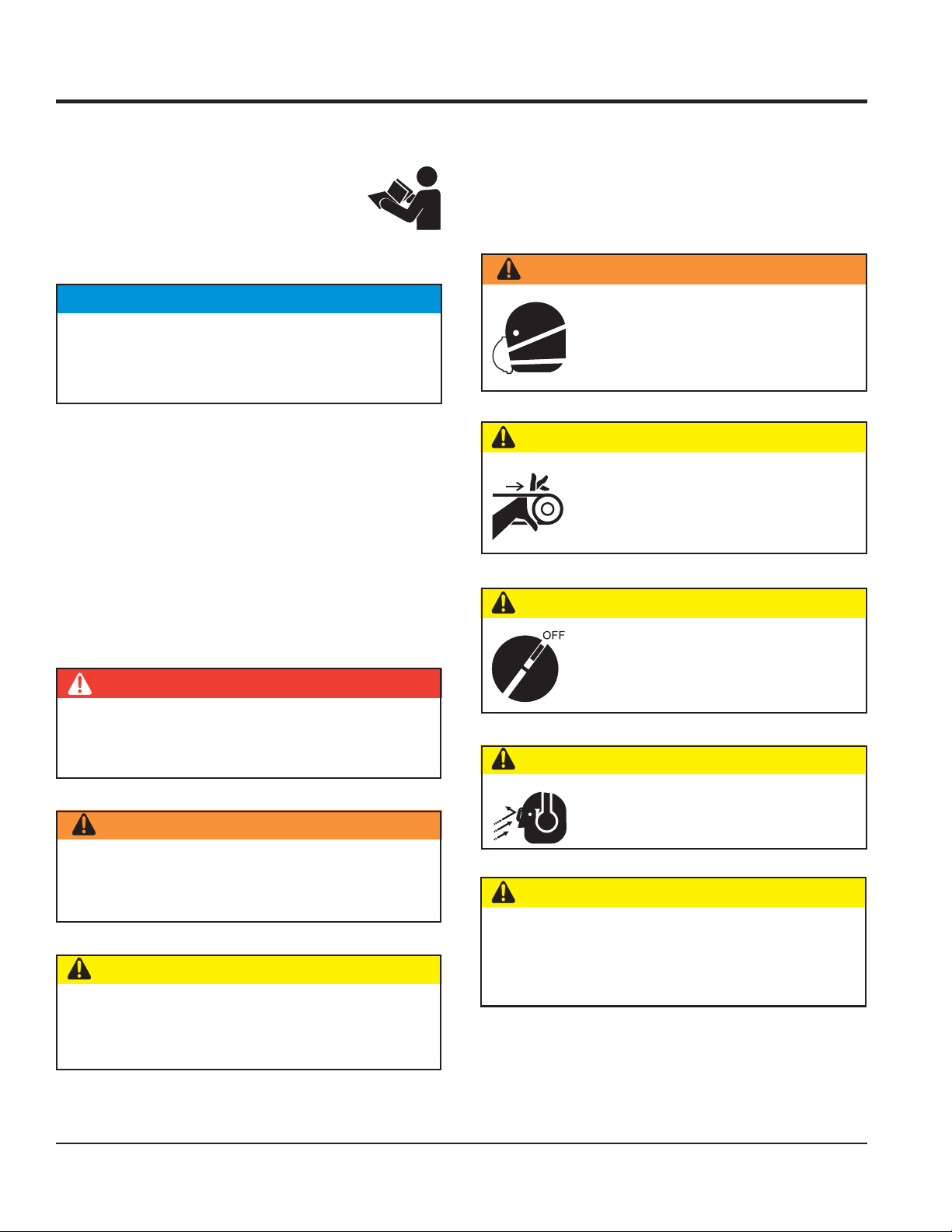
SAFETY MESSAGE ALERT SYMBOLS
The three Safety Messages shown below will inform you
about potential hazards that could injure you or others.
The Safety Messages specifically address the level of exposure to the operator, and are preceded by one of three
words: DANGER, WARNING, or CAUTION.
DANGER
HAZARD SYMBOLS
Potential hazards associated with the operation of this
equipment will be referenced with Hazard Symbols which
appear throughout this manual, and will be referenced in
conjunction with Safety Message Alert Symbols.
WARNING — Respiratory Hazards
ALWAYS wear approved respiratory
protection when required.
CAUTION — Rotating Parts Hazards
NEVER operate equipment with covers or
guards removed. Keep fingers, hands, hair
and clothing away from all moving parts to
prevent injury.
CAUTION — Accidental Starting Hazards
ALWAYS place the equipment ON/OFF
switch in the OFF position when the
equipment is not in use.
You WILL be
INJURED
directions.
WARNING
You CAN be KILLED or
KILLED
or
SERIOUSLY
if you DO NOT follow these
SERIOUSLY INJURED
CAUTION — Eye and Hearing Hazards
ALWAYS wear approved eye and hearing
protection.
if you DO NOT follow these directions.
CAUTION — Equipment Damage Hazards
Other important messages are provided throughout this
manual to help prevent damage to your equipment,
CAUTION
You CAN be
INJURED
if you DO NOT follow
other property, or the surrounding environment.
these directions.
PAGE 4 — HBC19B/HBC25B REBAR CUTTER • OPERATION AND PARTS MANUAL — REV. #1 (03/07/12)
Page 3
WARNING — Read This Manual
Failure to follow instructions in this manual may lead to
serious injury or even
operated by trained and qualified personnel only! This
equipment is for industrial use only.
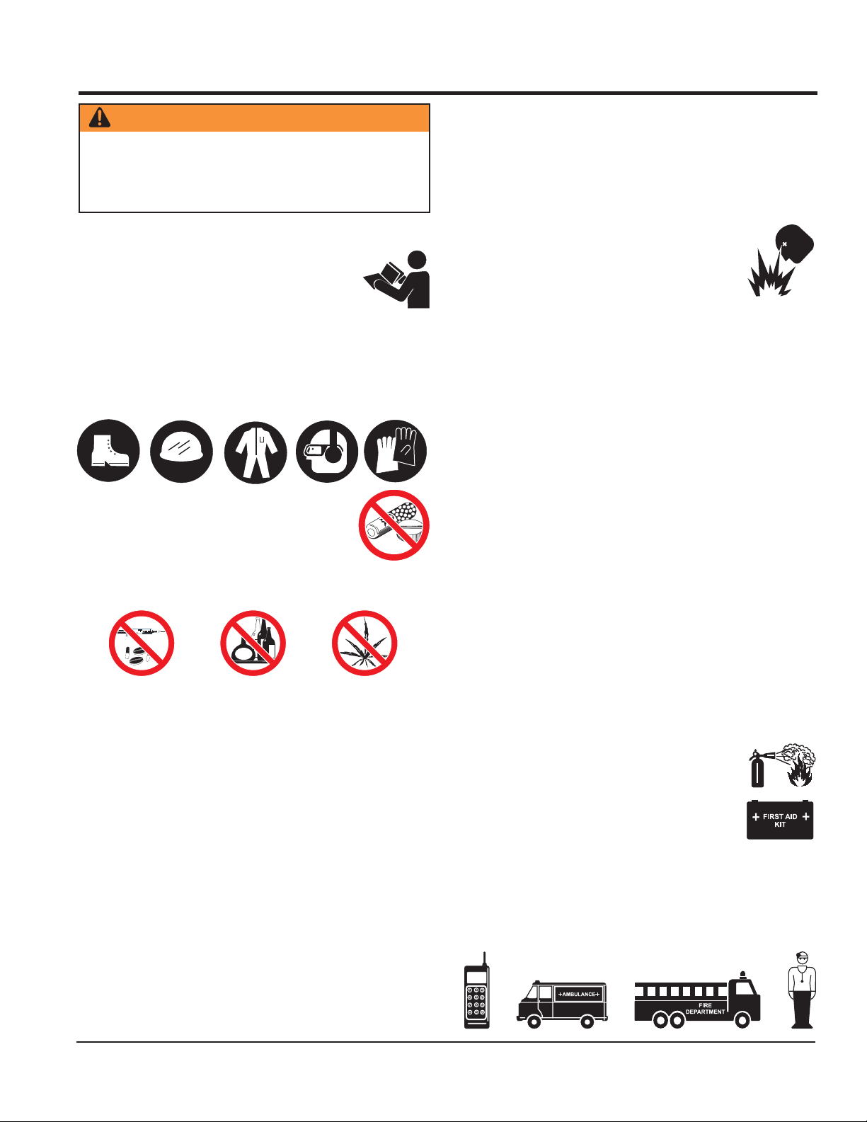
GENERAL SAFETY
DO NOT operate or service this equipment
before reading this entire manual.
This equipment should not be operated by
persons under 18 years of age.
NEVER operate this equipment without proper protective
clothing, shatterproof glasses, steel-toed boots and other
protective devices required by the job.
NEVER operate this equipment when not
feeling well due to fatigue, illness or when
under medication.
NEVER operate this equipment under the
influence of drugs or alcohol.
DEATH
! This equipment is to be
RULES AND REGULATIONS
DO NOT wear loose clothing or jewelry. Contain long
hair. Keep hair, clothing, and gloves away from moving
parts. Rotating parts can cause injury if contacted.
ALWAYS keep work area clean and free of foreign matter
and debris. Also keep work area well lit.
NEVER operate the equipment in an
explosive atmosphere or near combustible
materials. An explosion or fire could result
causing severe
death.
DO NOT overreach. Keep proper footing and balance at
all times.
NEVER leave the equipment unattended. When not is
use, before servicing, and when changing accessories,
always unplug the equipment from the power source.
USE this equipment for its intended purpose only.
KEEP equipment clean for better and safer performance.
Keep handles dry, clean, and free from oil and grease.
INSPECT the equipment after each use. Replace any
damaged or worn parts immediately. Do not use
equipment if defective.
If a malfunction occurs, immediately unplug the
equipment from the power source and correct the
problem. If problem cannot be corrected, contact the
nearest MQ service center.
bodily harm or even
ALWAYS store the equipment in a clean, dry location
NEVER use accessories or attachments that are not
recommended by Multiquip for this equipment. Damage
to the equipment and/or injury to user may result.
Manufacturer does not assume responsibility for any
accident due to equipment modifications. Unauthorized
equipment modification will void all warranties.
Whenever necessary, replace nameplate, operation and
safety decals when they become difficult to read.
ALWAYS check the equipment for loosened threads or
bolts before starting.
MAINTAIN equipment is a safe operating condition at
all times.
KEEP bystanders, children, and visitors away while
operating the equipment. Distractions can cause loss of
control.
HBC19B/HBC25B REBAR CUTTER • OPERATION AND PARTS MANUAL — REV. #1 (03/07/12) — PAGE 5
out of the reach of children.
EMERGENCIES
ALWAYS know the location of the nearest
fire extinguisher
ALWAYS know the location of the nearest
first aid kit
In emergencies,
of the nearest phone or
Also know the phone numbers of the nearest
ambulance, doctor
information will be invaluable in case of emergency.
.
.
always
and
know the location
keep a phone on the job site
fire department
. This
.
Page 4

RULES AND REGULATIONS
ELECTRICAL SAFETY
■
ALWAYS test the
POWER
switch on the equipment before
operating. The purpose of this switch is to shut down the
power.
■
NEVER use a extension cord that is frayed or damaged
where the insulation has been cut.
■
NEVER carry the equipment by its power cord or
disconnect it by yanking the cord from the power outlet.
■
ALWAYS make certain that the proper extension cord
has been selected for the job. See Extension Cord
Gauge Selection Table.
■
NEVER allow power cord to
■
NEVER
■
When connecting the unit to a power receptacle, make
stand in water
lay in wate
r.
while operating the equipment.
sure the receptacle circuit is connected to either a GFCI
receptacle or a receptacle protected by a 20 amp circuit
breaker.
■
When plugging the unit into a power receptacle, check
the nameplate for the correct operating voltage.
Operating the rebar bender at the wrong voltage will
damage the electrical components. ALWAYS read the
nameplate before applying power.
■
This unit is equipped with a 3-prong male power plug.
DO NOT use a 2-prong adapter when plugging into a
wall outlet. This will defeat the purpose of the ground
circuit. If the plug does not fit into the receptacle, contact
a qualified electrician to install a 3-conductor wall
receptacle (outlet).
■
Avoid body contact with grounded surfaces such as
pipes, radiators, ranges and refrigerators. There is an
increased risk of electrical shock if your body is
grounded.
■
DO NOT expose the hydraulic power unit to rain or wet
conditions. Water entering the power unit will increase
the risk of electrical shock.
■
When operating the unit outdoors, be sure to use the
appropriate outdoor extension cord. This type of
extension cord reduces the risk of electrical shock.
■
ALWAYS remove the AC power cord from the power
source before performing any service or maintenance
on the unit. This preventative safety measure reduces
the possibility of accidental starting.
When operating near an arc welder, it is important the
both the unit and the welding equipment be connected
to the same earth ground. If they are not, server damage
to the unit, particularly to the power cord could occur.
Personal injury may also occur.
noitceleSeguaGdroCnoisnetxE
stloV teeFnidroCfohtgneL
erepmA
gnitaR
egnaR
V511 .tF52 .tF05 .tF001 .tF051 .tF002 .tF052 .tF003 .tF004 .tF005
V032 .tF05 .tF001 .tF002 .tF003 .tF004 .tF005 .tF006 .tF008 .tF0001
2-0 81 81 81 61 61 41 41 21 21
3-2 81 81 61 41 41 21 21 01 01
4-3 81 81 61 41 21 21 01 01 8
5-4 81 81 41 21 21 01 01 8 8
6-5 81 61 41 21 01 01 8 8 6
8-6 81 61 21 01 01 8 6 6 6
01-8 81 41 21 01 8 8 6 6 4
21-01 61 41 01 8 8 6 6 4 4
41-21 61 21 01 8 6 6 6 4 2
61-41 61 21 01 8 6 6 4 4 2
81-61 41 21 8 8 6 4 4 2 2
02-81 41 21 8 6 6 4 4 2 2
PAGE 6 — HBC19B/HBC25B REBAR CUTTER • OPERATION AND PARTS MANUAL — REV. #1 (03/07/12)
Page 5

Model HBC19B HBC25B
Maximum Cutting Capacity
SPECIFICATIONS
Table 1. Specifications
Intermediate Grade (40)
70,000 psi (45 kg/mm
2
Hard Grade (50)
80,000 psi (55 kg/mm
2
High Tensile Strength
Grade (60)
90,000 psi (65 kg/mm
2
Cutting Speed
Rated Power
Amps
Power Source
Weight
Dimensions
Length 15.6 in (396.2 mm) 18.9 in (480 mm)
Width 4.4 in (111.8 mm) 5.4 in (137.2 mm)
)
)
No. 6, Size 3/4 in (19 mm) No. 8 Size 1 in (25 mm)
No. 6, Size 3/4 in (19 mm) No. 8 Size 1 in (25 mm)
No. 6, Size 3/4 in (19 mm) No. 8, Size 1 in (25 mm)
)
2.5 sec 3.5 sec
1330 W 1430 W
11 A 13 A
115 V single-phase AC 115 V single-phase AC
27 lb (12.25 kg) 48.5 lb (22 kg)
Height 8.7 in (221 mm) 10.6 in (269.2 mm)
Standard Equipment
Hydraulic Oil 5 oz (150 ml) 5 oz (150 ml)
Carrying Box Wooden Box Wooden Box
Allen Wrench 4 pieces (M3, 4, 5, 6) 4 pieces (M4, 5, 6, 8)
Open-End Wrench 0.67 x 0.75 in (17 x 19 mm)
0.55 x 0.67 in (14 x 17 mm)
0.94 in (24 mm)
HBC19B/HBC25B REBAR CUTTER • OPERATION AND PARTS MANUAL — REV. #1 (03/07/12) — PAGE 7
Page 6

GENERAL INFORMATION
GENERAL INFORMATION
The
MQ HBC19B/HBC25B Rebar Cutters
to be used as a portable on-site rebar cutter, capable of
cutting in-place rebar safely and efficiently with the squeeze
of a trigger. Labor time and injuries are greatly reduced
from manually cutting rebar. The cutter can virtually handle
any rebar cutting job, from slabs and masonry walls to large
buildings and bridges.
The rebar cutter contains a built-in hydraulic pump with
innovative magnetic particle filtering. All parts are machined
to tight tolerances for maximum performance.
are designed
At approximately 27 to 49 pounds, the cutter is easily carried around job sites. Even overhead work takes minimum
effort.
The cutting rod returns to the starting position when the
operating switch is released after the rod makes its full
cutting stroke. The cutting rod will not move if the cutting
stroke is not finished. The operating switched must be held
long enough for cutting rod to complete stroke.
The HC19B/HBC25B come with a return valve that allows
the cutter rod to return to the starting position when the
cutter blade jams and stops during cutting of a rebar.
PAGE 8 — HBC19B/HBC25B REBAR CUTTER • OPERATION AND PARTS MANUAL — REV. #1 (03/07/12)
Page 7

COMPONENTS
6
5
8
HBC19B
2
3
5
6
7
2
1
3
4
1
4
Figure 1. HBC19B/HBC25B Components
Figure 1 shows the components of the HBC19B/HBC25B
Rebar Cutter. These components are described below.
1. Blade (set of two) - Cuts the rebar that is set on the
6. Handle - Used to lift the rebar cutter.
holder between the blades.
7. Return Valve - Returns the cutter rod to the starting
2. Spacing Bolt and Nut - Allows rebar of different
diameters to be cut by adjusting the space between
the blades.
3. Rebar Holder - Holds the rebar to be cut.
4. Protector - Covers the rebar while cutting to prevent
position when the cutter blade jams and stops the
cutting of a rebar. This is done by rotating the return
valve half a turn in a counterclockwise direction with
the hexagonal wrench supplied with the unit.
8. Power Plug - Connects to a 150 V, 60 Hz power source.
rebar fragments from flying out.
HBC25B
7
8
5. ON/OFF Switch - Starts the cutting of the rebar when
the trigger switch is squeezed. When released, cutting
is stopped. Do not release release switch until the rebar
is completely cut.
HBC19B/HBC25B REBAR CUTTER • OPERATION AND PARTS MANUAL — REV. #1 (03/07/12) — PAGE 9
Page 8

OPERATION
CUTTING PROCEDURE
WARNING
Make sure that the bar is resting fully within the blades
and protector is in the upright position. If the rebar is
not properly set, the cutting piece or fragments of the
rebar may scatter as soon as rebar is cut and the cutter
can also be damaged.
1. Adjust the spacing bolt according to the diameter of
the rebar being cut. Bolt must allow rebar to be flush,
at 90° to the blades.
2. Connect the electric plug from the cutter to a proper
power source (115 volts, 60 Hz).
3. Place the rebar in the rebar holder. Rebar must rest
fully within the blades. See Figure 2. Position the
protector over the surface to be cut.
Figure 2. Rebar Placement
4. Tighten the spacing bolt and jam nut to hold the rebar
in place.
WARNING
Do not cut rebar when it is not properly supported by
the spacing bolt or if the spacing bolt is not properly
adjusted. When cutting, hold the rebar on the spacing
bolt side as shown below. If not, the cut piece may fly
off and cause serious injury to the operator or
bystanders.
NEVER use worn or damaged blades. Replace
immediately before using cutter again.
WARNING
Replace damaged (broken and cracked edge) or
deformed cutter as soon as possible. Damaged cutter
could cause the rebar to be get out of place or cracked
during cutting. This may cause a serious accident. Do
not cut rebar that is less than 8 inches (200 mm) in
length asthis may cause rebar to fly off and result to
personal injury.
CAUTION
5. Squeeze the ON/OFF switch to start cutting the rebar.
Keep holding the ON/OFF switch until the cuting rod
completes cutting cycle. Do not attempt to partially cut
through the diameter of the rebar. This will cause
damage to the blades and cause the rebar to fly out.
6. At the end of the cutting cycle, release the ON/OFF
switch. The cutter rod will retract automatically.
7. If cutter reaches 158° F or higher, stop cutting operation
and allow machine to cool before using again.
8. Periodically inspect oil level and electric motor brushes.
Refer to Maintenance section for details.
PAGE 10 — HBC19B/HBC25B REBAR CUTTER • OPERATION AND PARTS MANUAL — REV. #1 (03/07/12)
WARNING
Keep hands and face away from the blades
and other rotating or sliding parts during
operation.
RETURN VALVE OPERATION
The return valve is used when the cutter blade jams and
stops during cutting of the rebar.
1. Rotate the return valve half a turn in the
counterclockwise direction with the allen wrench (no. 4)
supplied with the unit. See Figure 3 for location.
Page 9

RETURN VALVE
REMOVE 2 BOLTS
TO REMOVE COVER
USE STANDARD
SCREWDRIVER
TO REMOVE CAP
CARBON
BRUSH
Figure 3. Return Valve
2. The cutter rod will retract and return to its starting
position.
3. Once the cutter rod returns to its starting position,
tighten the return valve before resuming rebar cutting.
DANGER
OPERATION
5-6 MM
(1/4 INCH)
Figure 4. Carbon Brush Size
1. Make sure that the power plug is not connected to the
power source.
2. For the HBC19B, remove the 2 bolts holding the cover
using a 4mm allen-head wrench then remove the cover
to access the two carbon brush caps (one on each
side). See Figure 5.
During operation of this rebar cutter, there
exists the possibility of
electrical shock or burn,
cause
severe bodily harm
electrocution,
which can
or even
DEATH!
To avoid these hazards:
NEVER use damaged or worn cables
WET
HANDS
when plugging the rebar cutter into
an AC power receptacle.
NEVER grab or touch a live power
cord with wet hands.
POWER
CORD
(POWER ON)
NEVER stand in water and touch a live power cord.
WARNING
Unplug unit from power source before replacing carbon
brushes.
REPLACING CARBON BRUSHES
Figure 5. Replacing Carbon Brushes (HBC19B)
CARBON BRUSH CAP
Figure 6. Replacing Carbon Brushes (HBC25B)
3. Remove the carbon brush cap of the motor outer frame
using a standard screwdriver. See Figures 5 and 6.
When the carbon becomes less than 5 or 6 mm (1/4 inch)
the motor force deteriorates because of low rectification
(Figure 4). The carbon brushes need to be replaced at this
4. Replace the carbon brushes with new ones (two for
the HBC19B and one for the HBC25B).
5. Put back the cap after brush is installed.
time. It is also recommended that the brushes be replaced
after 200 hours of use.
HBC19B/HBC25B REBAR CUTTER • OPERATION AND PARTS MANUAL — REV. #1 (03/07/12) — PAGE 11
6. For the HBC19B, replace cover and tighten 2 bolts.
Page 10

MAINTENANCE
REPLACING OIL
The rebar cutter uses hydraulic action to operate. If there
is insufficient, dirty, or improper oil in the cutter, it will not
operate at full capacity. If unit is not operating properly,
check oil level and condition. If necessary, replace oil as
follows:
1. Loosen oil fill bolt with the supplied open-end wrench
Remove oil fill bolt and lay cutter to allow to oil to drain
out. See Figure 7.
REMOVE
BOLT
Figure 7. Removing Oil Fill Bolt
Model HBC19B HBC25B
Quantity 5 oz (150 ml) 5 oz (150 ml)
Oil Type
Above grades are blended to viscosity values that
conform to the ISO (International St
Organization) viscosity classification system.
3. Shake the cutter up and down to release any air bubble
4. Overfill with oil again.
5. Replace bolt in fill port and wipe off any excess oil.
6. Connect the cutter power cord to the power source.
Table 2. Oil Type
Shell Tellus Oil #46
Exxon Teresstic #46
that may be present.
Place a 3/16-inch diameter steel rod in bar holder.
Squeeze ON/OFF switch to activate the cutter and
allow the blade to touch the rod then turn off then
release the ON/OFF switch.
Shell Tellus Oil #32
Exxon Teresstic #32
andards
2. Turn cutter so that the oil fill port is on the top side. Fill
with oil until it overflows. See Figure 8. See Table 2 for
oil type and quantity.
FILL WITH OIL
Figure 8. Oil Fill
7. Turn cutter so that the oil fill port is on the top side
once again. Repeat oil fill procedure.
8. Squeeze ON/OFF switch again to continue and finish
cutting operation started earlier.
9. When cutting is complete, filling procedure is done.
WARNING
Unplug unit from power source before troubleshooting.
PAGE 12 — HBC19B/HBC25B REBAR CUTTER • OPERATION AND PARTS MANUAL — REV. #1 (03/07/12)
Page 11

MAINTENANCE
gnitoohselbuorT.3elbaT
motpmySmelborPelbissoPnoituloS
?tneiciffusnisiliO
oteudyletelpmoctcartertondiddorrettuC
dnaredwopnori,spihcleetstnemecrofnier
ehtfonoitropgnidilsehtnitneserptrid
.kcutssidorrettuC
?edalb
?tneiciffusnisiliO
?reporpmi
orrettuC
tuosemocd
sirewopgnittuctub
.rabertucotkaewoot
?notsip
?redlohrabehtdnadorrettuc
telpmoctcartertondiddorrettuC
?gnirpsnruterdorrettuckaewa
?nekorbevlavesaelersI.evlavesael
oteudyle
dorrettucfognillewsronoitrotsideht
oteudyletelpmoctcartertondiddorrettuC
evlavesaelerdnarednilycneewtebtcatnoC
si)rednilycninoitcejorpfoecafruspit(
dnarednilycneewtebecnaraelcreporpmI
.noitces
iT
.edalb
ces
.noit
erecalpeR
itcurtsnieeS.lioddA
.gnirpsnruterecalpeR
erehttahterusekaM
.tridroredwopnori
.notsipdnarednilycecalpeR
ecnanetniaMnisno
.dorrettucnaelC.dorrettuckcabhsuP
dorrettucecalpeR.stlobedalbnethg
ecnanetniaMnisnoitcurtsnieeS.lioddA
tasehctarcsonera
kcutsynanaelC.rednilycfoecafrusfopit
reporpmI
?evlav
.gnikaelsiliO
?egatlovtcerrocnI
etatortonseodrotoM
rotomroopro
.noitator
.erutamrafo
?sehsurbnobracfonoisarbA.sehsurbnobracecalpeR
ETON
decivresebdluohsstnenopmoclacirtcelelladna
esotlennosrepdezirohtuanu
dnarednilycneewtebtcatnoc
?gnikcaprebburrednilycnekorB.gnikcaprebburecalpeR
casrelevellionekorbrodehctarcS.trapevitcefedecalpeR
?k
?rednilycdnaredilsredlohrabdehctarcS.trapevitcefedec
?esacpmupdnareniltniojrednilycnekorB.trapevitcefedecalpeR
?tlobllifliofogninethgittneiciffusnI.tlob
sdnehtobtasgniraebdemrofedronekorB
resesuacdluoctahtsnoitidnocotdaelnacstnenopmoclacritcele
alpeR
aM
.ecruos
.tnempiuqetcerrocehthtiwlennosrepdeniartylreporpybenodebtsumpmup
.evlavdnarednilycecalpeR
lliflionethgiT
rewopreporpottcennocsitinuerusek
niraebecalpeR
.sg
evitisneserasecnaraelcesolcyrevevahaeranotsipdnapmupciluardyhehtfostnenopmoclanretniehT:
sidehT.gnildnahreporpmirodiulfciluardyhehtfonoitanimatnoc,trid,tsudmorfegamadot
.ytnarrawehtdiovlliwrettucraberehtfostnenopmoclanretniecivr
ehtfoylbmessa
fognicivresreporpmiehT
stnenopmocnotsipdnapmupehT.yrujnisuoi
ybtpmettaynA.retnecriaperdezirohtuayrotcafayb
HBC19B/HBC25B REBAR CUTTER • OPERATION AND PARTS MANUAL — REV. #1 (03/07/12) — PAGE 13
 Loading...