

Page 1

OPERATION AND PARTS MANUAL
MODEL HBC19A
MODEL HBC25A
REBAR CUTTER
(PORTABLE ELECTRIC)
Revision #4 (03/30/09)
To find the latest revision of this
publication, visit our website at:
www.multiquip.com
THIS MANUAL MUST ACCOMPANY THE EQUIPMENT AT ALL TIMES.
Page 2

HBC19A/HBC25A REBAR
CUTTER
Table of Contents .................................................... 2
Parts Ordering Procedures ..................................... 3
Safety ...................................................................... 4
Rules and Regulations ......................................... 5-6
Specifications .......................................................... 7
General Information ................................................ 8
Components ............................................................ 9
Operation ......................................................... 10-11
Maintenance..................................................... 12-13
Explanation of Codes in Remarks Column ........... 14
Suggested Spare Parts ......................................... 15
COMPONENT DRAWINGS
Nameplate and Decals ..................................... 16-17
HBC19A Rebar Cutter Assembly ..................... 18-21
HBC25A Rebar Cutter Assembly ..................... 22-25
Tools ................................................................. 26-27
Wiring Diagram ..................................................... 28
TABLE OF CONTENTS
Terms and Conditions Of Sale — Parts ................ 29
Specification and part number are
subject to change without notice.
PAGE 2 — HBC19A/HBC25A REBAR CUTTER • OPERATION AND PARTS MANUAL — REV. #4 (03/30/09)
Page 3
PARTS ORDERING PROCEDURES
Ordering parts has never been easier!
Choose from three easy options:
January 1
Effective:
st
, 2006
Best Deal!
Order via Internet (Dealers Only):
Order parts on-line using Multiquip’s SmartEquip website!
N View Parts Diagrams
N Order Parts
N Print Specification Information
Goto www.multiquip.com and click on
Order Par ts
Order via Fax (Dealers Only):
All customers are welcome to order parts via Fax.
Domestic (US) Customers dial:
1-800-6-PARTS-7 (800-672-7877)
Non-Dealer Customers:
Contact your local Multiquip Dealer for
parts or call 800-427-1244 for help in
locating a dealer near you.
to log in and save!
Order via Phone:
If you have an MQ Account, to obtain a Username
and Password, E-mail us at: parts@multiquip.
com.
To obtain an MQ Account, contact your
District Sales Manager for more information.
Use the internet and qualify for a 5% Discount
on Standard orders for all orders which include
complete part numbers.*
Note: Discounts Are Subject To Change
Fax your order in and qualify for a 2% Discount
on Standard orders for all orders which include
complete part numbers.*
Note: Discounts Are Subject To Change
Domestic (US) Dealers Call:
1-800-427-1244
International Customers should contact
their local Multiquip Representatives for
Parts Ordering information.
When ordering parts, please supply:
R Dealer Account Number
R Dealer Name and Address
R Shipping Address (if different than billing address)
R Return Fax Number
R Applicable Model Number
R Quantity, Part Number and Description of Each Part
NOTICE
All orders are treated as Standard Orders and will
ship the same day if received prior to 3PM PST.
R Specify Preferred Method of Shipment:
UPS/Fed Ex DHL
N Priority One Tr uck
N Ground
N Next Day
N Second/Third Day
www.multiquip.com
WE ACCEPT ALL MAJOR CREDIT CARDS!
HBC19A/HBC25A REBAR CUTTER • OPERATION AND PARTS MANUAL — REV. #4 (03/30/09) — PAGE 3
Page 4

SAFETY
FOR YOUR SAFETY AND SAFETY OF OTHERS!
Safety precautions should be followed at all
times when operating this equipment. Failure to read and understand the Safety Messages and Operating Instructions could result
in injury to yourself and others.
This manual has been developed to
provide complete instructions for the
safe and efficient operation of this
equipment.
Before using this equipment ensure that the operating individual has read and understood all instructions in this
manual.
SAFETY MESSAGE ALERT SYMBOLS
HAZARD SYMBOLS
Potential hazards associated with the operation of this
equipment will be referenced with Hazard Symbols which
appear throughout this manual, and will be referenced in
conjunction with Safety Message Alert Symbols.
WARNING — Respiratory Hazards
ALWAYS wear approved respiratory
protection when required.
CAUTION — Rotating Parts Hazards
NEVER operate equipment with covers or
guards removed. Keep fingers, hands, hair
and clothing away from all moving parts to
prevent injury.
The three Safety Messages shown below will inform you
about potential hazards that could injure you or others.
The Safety Messages specifically address the level of exposure to the operator, and are preceded by one of three
words: DANGER, WARNING, or CAUTION.
DANGER
You WILL be
INJURED
KILLED
or
SERIOUSLY
if you DO NOT follow these
directions.
WARNING
You CAN be KILLED or
SERIOUSLY INJURED
if you DO NOT follow these directions.
CAUTION
CAUTION — Accidental Starting Hazards
ALWAYS place the equipment ON/OFF
switch in the OFF position when the
equipment is not in use.
CAUTION — Eye and Hearing Hazards
ALWAYS wear approved eye and hearing
protection.
CAUTION — Equipment Damage Hazards
Other important messages are provided throughout this
manual to help prevent damage to your equipment,
other property, or the surrounding environment.
You CAN be
INJURED
if you DO NOT follow
these directions.
PAGE 4 — HBC19A/HBC25A REBAR CUTTER • OPERATION AND PARTS MANUAL — REV. #4 (03/30/09)
Page 5
WARNING — Read This Manual
Failure to follow instructions in this manual may lead to
serious injury or even
operated by trained and qualified personnel only! This
equipment is for industrial use only.
GENERAL SAFETY
DO NOT operate or service this equipment
before reading this entire manual.
This equipment should not be operated by
persons under 18 years of age.
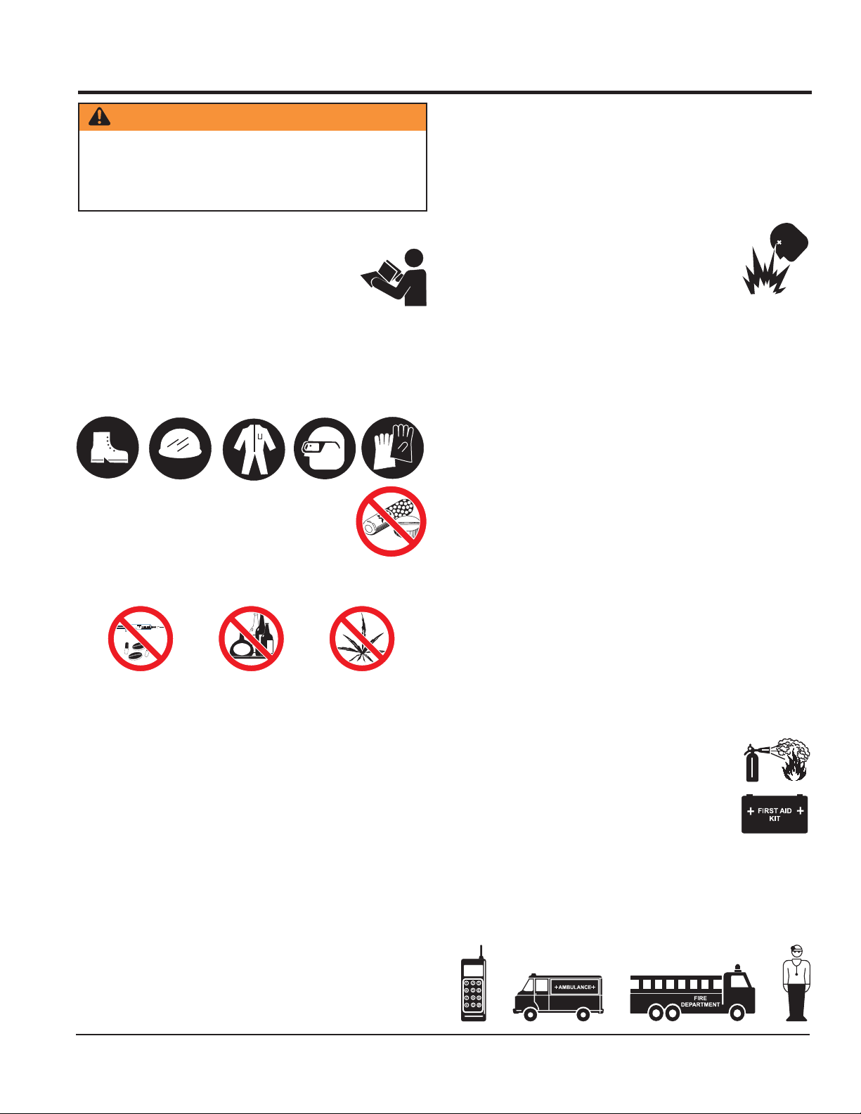
NEVER operate this equipment without proper protective
clothing, shatterproof glasses, steel-toed boots and other
protective devices required by the job.
NEVER operate this equipment when not
feeling well due to fatigue, illness or when
under medication.
NEVER operate this equipment under the
influence of drugs or alcohol.
DEATH
! This equipment is to be
RULES AND REGULATIONS
DO NOT wear loose clothing or jewelry. Contain long
hair. Keep hair, clothing, and gloves away from moving
parts. Rotating parts can cause injury if contacted.
ALWAYS keep work area clean and free of foreign matter
and debris. Also keep work area well lit.
NEVER operate the equipment in an
explosive atmosphere or near combustible
materials. An explosion or fire could result
causing severe
death.
DO NOT overreach. Keep proper footing and balance at
all times.
NEVER leave the equipment unattended. When not is
use, before servicing, and when changing accessories,
always unplug the equipment from the power source.
USE this equipment for its intended purpose only.
KEEP equipment clean for better and safer performance.
Keep handles dry, clean, and free from oil and grease.
INSPECT the equipment after each use. Replace any
damaged or worn parts immediately. Do not use
equipment if defective.
If a malfunction occurs, immediately unplug the
equipment from the power source and correct the
problem. If problem cannot be corrected, contact the
nearest MQ service center.
bodily harm or even
ALWAYS store the equipment in a clean, dry location
NEVER use accessories or attachments that are not
recommended by Multiquip for this equipment. Damage
to the equipment and/or injury to user may result.
Manufacturer does not assume responsibility for any
accident due to equipment modifications. Unauthorized
equipment modification will void all warranties.
Whenever necessary, replace nameplate, operation and
safety decals when they become difficult to read.
ALWAYS check the equipment for loosened threads or
bolts before starting.
MAINTAIN equipment is a safe operating condition at
all times.
KEEP bystanders, children, and visitors away while
operating the equipment. Distractions can cause loss of
control.
HBC19A/HBC25A REBAR CUTTER • OPERATION AND PARTS MANUAL — REV. #4 (03/30/09) — PAGE 5
out of the reach of children.
EMERGENCIES
ALWAYS know the location of the nearest
fire extinguisher
ALWAYS know the location of the nearest
first aid kit
In emergencies,
of the nearest phone or
Also know the phone numbers of the nearest
ambulance, doctor
information will be invaluable in case of emergency.
.
.
always
and
know the location
keep a phone on the job site
fire department
. This
.
Page 6

RULES AND REGULATIONS
ELECTRICAL SAFETY
■
ALWAYS test the
POWER
switch on the equipment before
operating. The purpose of this switch is to shut down the
power.
■
NEVER use a extension cord that is frayed or damaged
where the insulation has been cut.
■
NEVER carry the equipment by its power cord or
disconnect it by yanking the cord from the power outlet.
■
ALWAYS make certain that the proper extension cord
has been selected for the job. See Extension Cord
Gauge Selection Table.
■
NEVER allow power cord to
■
NEVER
■
When connecting the unit to a power receptacle, make
stand in water
lay in wate
r.
while operating the equipment.
sure the receptacle circuit is connected to either a GFCI
receptacle or a receptacle protected by a 20 amp circuit
breaker.
■
When plugging the unit into a power receptacle, check
the nameplate for the correct operating voltage.
Operating the rebar bender at the wrong voltage will
damage the electrical components. ALWAYS read the
nameplate before applying power.
■
This unit is equipped with a 3-prong male power plug.
DO NOT use a 2-prong adapter when plugging into a
wall outlet. This will defeat the purpose of the ground
circuit. If the plug does not fit into the receptacle, contact
a qualified electrician to install a 3-conductor wall
receptacle (outlet).
■
Avoid body contact with grounded surfaces such as
pipes, radiators, ranges and refrigerators. There is an
increased risk of electrical shock if your body is
grounded.
■
DO NOT expose the hydraulic power unit to rain or wet
conditions. Water entering the power unit will increase
the risk of electrical shock.
■
When operating the unit outdoors, be sure to use the
appropriate outdoor extension cord. This type of
extension cord reduces the risk of electrical shock.
■
ALWAYS remove the AC power cord from the power
source before performing any service or maintenance
on the unit. This preventative safety measure reduces
the possibility of accidental starting.
When operating near an arc welder, it is important the
both the unit and the welding equipment be connected
to the same earth ground. If they are not, server damage
to the unit, particularly to the power cord could occur.
Personal injury may also occur.
noitceleSeguaGdroCnoisnetxE
stloV teeFnidroCfohtgneL
erepmA
gnitaR
egnaR
V511 .tF52 .tF05 .tF001 .tF051 .tF002 .tF052 .tF003 .tF004 .tF005
V032 .tF05 .tF001 .tF002 .tF003 .tF004 .tF005 .tF006 .tF008 .tF0001
2-0 81 81 81 61 61 41 41 21 21
3-2 81 81 61 41 41 21 21 01 01
4-3 81 81 61 41 21 21 01 01 8
5-4 81 81 41 21 21 01 01 8 8
6-5 81 61 41 21 01 01 8 8 6
8-6 81 61 21 01 01 8 6 6 6
01-8 81 41 21 01 8 8 6 6 4
21-01 61 41 01 8 8 6 6 4 4
41-21 61 21 01 8 6 6 6 4 2
61-41 61 21 01 8 6 6 4 4 2
81-61 41 21 8 8 6 4 4 2 2
02-81 41 21 8 6 6 4 4 2 2
PAGE 6 — HBC19A/HBC25A REBAR CUTTER • OPERATION AND PARTS MANUAL — REV. #4 (03/30/09)
Page 7

SPECIFICATIONS
snoitacificepS.1elbaT
ledoMA91CBHA52CBH
yticapaCgnittuCmumixaM
)04(edarGetaidemretnI
2
)
mm/gk54(isp000,07
)05(edarGdraH
2
)
mm/gk55(isp000,08
)06(edarGhtgnertSelisneThgiH
2
)
mm/gk56(isp000,09
deepSgnittuC
rewoPdetaR
spmA
ces5.2ces5.3
W0331W0341
A11A31
ecruoSrewoP
thgieW
)mm91(ni4/3eziS,6.oN)mm52(ni1eziS8.oN
)mm91(ni4/3eziS,6.oN)mm52(ni1eziS8.oN
)mm91(ni4/3eziS,6.oN)mm52(ni1eziS,8.oN
Aesahp-elgnisV511CAesahp-elgnisV511
C
)gk52.21(bl72)gk22(bl5.84
snoisnemiD
htgneL)mm2.693(ni6.51)mm084(n
htdiW)mm8.111(ni4.4)mm2.731(ni4.5
i9.81
thgieH)mm122(ni7.8)mm2.962(ni6.01
tnempiuqEdradnatS
hcnerWnellA)6,5,4,
3M(seceip4)8,6,5,4M(seceip4
liOciluardyH)lm051(zo5)lm051(zo5
xoBgniyrraCxoBnedooWxoBnedooW
hcnerWdnE-nepO)mm91
x71(ni57.0x76.0)mm42,71x41(ni49.0,76.0x55.0
HBC19A/HBC25A REBAR CUTTER • OPERATION AND PARTS MANUAL — REV. #4 (03/30/09) — PAGE 7
Page 8

GENERAL INFORMATION
GENERAL INFORMATION
The
MQ HBC19A/HBC25A Rebar Cutter
be used as a portable on-site rebar cutter, capable of cutting in-place rebar safely and efficiently with the squeeze
of a trigger. Labor time and injuries are greatly reduced
from manually cutting rebar. The cutter can virtually handle
any rebar cutting job, from slabs and masonry walls to large
buildings and bridges.
The rebar cutter contains a built-in hydraulic pump with
innovative magnetic particle filtering. All parts are machined
to tight tolerances for maximum performance.
is designed to
At approximately 27 to 49 pounds, the cutter is easily carried around job sites. Even overhead work takes minimum
effort.
The cutting rod returns to the starting position when the
operating switch is released after the rod makes its full
cutting stroke. The cutting rod will not move if the cutting
stroke is not finished. The operating switched must be held
long enough for cutting rod to complete stroke.
The HC19A/HBC25A comes with a return valve that allows the cutter rod to return to the starting position when
the cutter blade jams and stops during cutting of a rebar.
PAGE 8 — HBC19A/HBC25A REBAR CUTTER • OPERATION AND PARTS MANUAL — REV. #4 (03/30/09)
Page 9
COMPONENTS
HBC19A
HBC25A
1
1
4
4
2
2
3
3
5
5
7
7
8
8
6
6
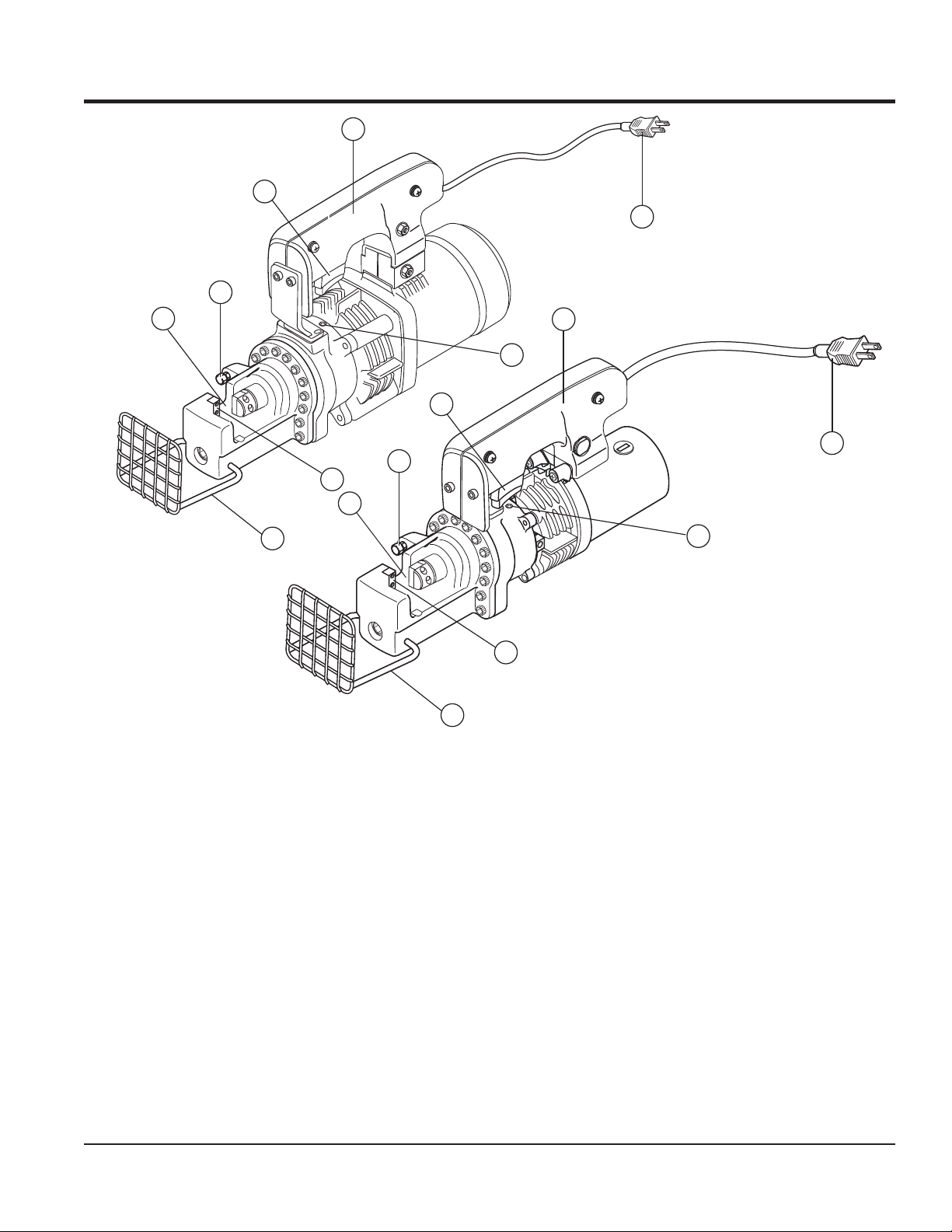
Figure 1. HBC19A/HBC25A Components
Figure 1 shows the components of the HBC19A/HBC25A
Rebar Cutter. These components are described below.
1. Blade (set of two) - Cuts the rebar that is set on the
holder between the blades.
2. Spacing Bolt and Nut - Allows rebar of different
diameters to be cut by adjusting the space between
the blades.
3. Rebar Holder - Holds the rebar to be cut.
4. Protector - Covers the rebar while cutting to prevent
rebar fragments from flying out.
5. ON/OFF Switch - Starts the cutting of the rebar when
the trigger switch is squeezed. When released, cutting
is stopped. Do not release release switch until the rebar
is completely cut.
6. Handle - Used to lift the rebar cutter.
7. Return Valve - Returns the cutter rod to the starting
position when the cutter blade jams and stops the
cutting of a rebar. This is done by rotating the return
valve half a turn in a counterclockwise direction with
the hexagonal wrench supplied with the unit.
8. Power Plug - connects to a 150 V, 60 Hz power source.
HBC19A/HBC25A REBAR CUTTER • OPERATION AND PARTS MANUAL — REV. #4 (03/30/09) — PAGE 9
Page 10

OPERATION
CUTTING PROCEDURE
WARNING
Make sure that the bar is resting fully within the blades
and protector is in the upright position. If the rebar is
not properly set, the cutting piece or fragments of the
rebar may scatter as soon as rebar is cut and the cutter
can also be damaged.
1. Adjust the spacing bolt according to the diameter of
the rebar being cut. Bolt must allow rebar to be flush,
at 90° to the blades.
2. Connect the electric plug from the cutter to a proper
power source (115 volts, 60 Hz).
3. Place the rebar in the rebar holder. Rebar must rest
fully within the blades. See Figure 2. Position the
protector over the surface to be cut.
Figure 2. Rebar Placement
4. Tighten the spacing bolt and jam nut to hold the rebar
in place.
WARNING
Do not cut rebar when it is not properly supported by
the spacing bolt or if the spacing bolt is not properly
adjusted. When cutting, hold the rebar on the spacing
bolt side as shown below. If not, the cut piece may fly
off and cause serious injury to the operator or
bystanders.
NEVER use worn or damaged blades. Replace
immediately before using cutter again.
WARNING
Replace damaged (broken and cracked edge) or
deformed cutter as soon as possible. Damaged cutter
could cause the rebar to be get out of place or cracked
during cutting. This may cause a serious accident. Do
not cut rebar that is less than 8 inches (200 mm) in
length asthis may cause rebar to fly off and result to
personal injury.
CAUTION
5. Squeeze the ON/OFF switch to start cutting the rebar.
Keep holding the ON/OFF switch until the cuting rod
completes cutting cycle. Do not attempt to partially cut
through the diameter of the rebar. This will cause
damage to the blades and cause the rebar to fly out.
6. At the end of the cutting cycle, release the ON/OFF
switch. The cutter rod will retract automatically.
7. If cutter reaches 158° F or higher, stop cutting operation
and allow machine to cool before using again.
8. Periodically inspect oil level and electric motor brushes.
Refer to Maintenance section for details.
PAGE 10 — HBC19A/HBC25A REBAR CUTTER • OPERATION AND PARTS MANUAL — REV. #4 (03/30/09)
WARNING
Keep hands and face away from the blades
and other rotating or sliding parts during
operation.
RETURN VALVE OPERATION
The return valve is used when the cutter blade jams and
stops during cutting of the rebar.
1. Rotate the return valve half a turn in the
counterclockwise direction with the allen wrench (no. 4)
supplied with the unit. See Figure 3 for location.
Page 11

RETURN VALVE
5-6 MM
(1/4 INCH)
Figure 3. Return Valve
2. The cutter rod will retract and return to its starting
position.
3. Once the cutter rod returns to its starting position,
tighten the return valve before resuming rebar cutting.
DANGER
OPERATION
Figure 4. Carbon Brush Size
1. Make sure that the power plug is not connected to the
power source.
2. For the HBC19A, remove the 2 bolts holding the cover
using a 4mm allen-head wrench then remove the cover
to access the two carbon brush caps (one on each
side). See Figure 5.
REMOVE 2 BOLTS
TO REMOVE COVER
During operation of this rebar cutter, there
exists the possibility of
electrical shock or burn,
cause
severe bodily harm
electrocution,
which can
or even
DEATH!
To avoid these hazards:
Figure 5. Replacing Carbon Brushes (HBC19A)
NEVER use damaged or worn cables when plugging
the rebar cutter into an AC power
receptacle.
WET
HANDS
3. Remove the carbon brush cap of the motor outer frame
using a standard screwdriver. See Figures 5 and 6.
NEVER grab or touch a live power
cord with wet hands.
NEVER stand in water and touch a
live power cord.
POWER
CORD
(POWER ON)
WARNING
Unplug unit from power source before replacing carbon
brushes.
REPLACING CARBON BRUSHES
When the carbon becomes less than 5 or 6 mm (1/4 inch)
the motor force deteriorates because of low rectification
Figure 6. Replacing Carbon Brushes (HBC25A)
4. Replace the carbon brushes with new ones (two for
the HBC19A and one for the HBC25A).
5. Put back the cap after brush is installed.
(Figure 4). The carbon brushes need to be replaced at this
time. It is also recommended that the brushes be replaced
6. For the HBC19A, replace cover and tighten 2 bolts.
after 200 hours of use.
USE STANDARD
CARBON
BRUSH
CARBON BRUSH CAP
SCREWDRIVER
TO REMOVE CAP
HBC19A/HBC25A REBAR CUTTER • OPERATION AND PARTS MANUAL — REV. #4 (03/30/09) — PAGE 11
Page 12

MAINTENANCE
REPLACING OIL
The rebar cutter uses hydraulic action to operate. If there
is insufficient, dirty, or improper oil in the cutter, it will not
operate at full capacity. If unit is not operating properly,
check oil level and condition. If necessary, replace oil as
follows:
1. Loosen oil fill bolt with the supplied open-end wrench
Remove oil fill bolt and lay cutter to allow to oil to drain
out. See Figure 7.
REMOVE
BOLT
3. Shake the cutter up and down to release any air bubble
4. Overfill with oil again.
5. Replace bolt in fill port and wipe off any excess oil.
6. Connect the cutter power cord to the power source.
Figure 7. Removing Oil Fill Bolt
epyTliO.2elbaT
ledoMA91CBHA52CBH
ytitnauQ)lm051(zo5)lm051(zo5
epyTliO
tmrofnoc
that may be present.
Place a 3/16-inch diameter steel rod in bar holder.
Squeeze ON/OFF switch to activate the cutter and
allow the blade to touch the rod then turn off then
release the ON/OFF switch.
64#liOsulleTllehS
64#citssereTnoxxE
OsulleTllehS
23#li
23#citssereTnoxxE
tahtseulavytisocsivotdednelberasedargevobA
sdradnatSlanoitanretnI(OSIehto
.metsysnoitacifissalcytisocsiv)noitazinagrO
2. Turn cutter so that the oil fill port is on the top side. Fill
with oil until it overflows. See Figure 8. See Table 2 for
oil type and quantity.
FILL WITH OIL
Figure 8. Oil Fill
7. Turn cutter so that the oil fill port is on the top side
once again. Repeat oil fill procedure.
8. Squeeze ON/OFF switch again to continue and finish
cutting operation started earlier.
9. When cutting is complete, filling procedure is done.
WARNING
Unplug unit from power source before troubleshooting.
PAGE 12 — HBC19A/HBC25A REBAR CUTTER • OPERATION AND PARTS MANUAL — REV. #4 (03/30/09)
Page 13

MAINTENANCE
gnitoohselbuorT.3elbaT
motpmySmelborPelbissoPnoituloS
?tneiciffusnisiliO
oteudyletelpmoctcartertondiddorrettuC
dnaredwopnori,spihcleetstnemecrofnier
ehtfonoitropgnidilsehtnitneserptrid
.kcutssidorrettuC
?edalb
?tneiciffusnisiliO
?reporpmi
orrettuC
tuosemocd
sirewopgnittuctub
.rabertucotkaewoot
?notsip
?redlohrabehtdnadorrettuc
telpmoctcartertondiddorrettuC
?gnirpsnruterdorrettuckaewa
?nekorbevlavesaelersI.evlavesael
oteudyle
dorrettucfognillewsronoitrotsideht
oteudyletelpmoctcartertondiddorrettuC
evlavesaelerdnarednilycneewtebtcatnoC
si)rednilycninoitcejorpfoecafruspit(
dnarednilycneewtebecnaraelcreporpmI
.noitces
iT
.edalb
ces
.noit
erecalpeR
itcurtsnieeS.lioddA
.gnirpsnruterecalpeR
erehttahterusekaM
.tridroredwopnori
.notsipdnarednilycecalpeR
ecnanetniaMnisno
.dorrettucnaelC.dorrettuckcabhsuP
dorrettucecalpeR.stlobedalbnethg
ecnanetniaMnisnoitcurtsnieeS.lioddA
tasehctarcsonera
kcutsynanaelC.rednilycfoecafrusfopit
reporpmI
?evlav
.gnikaelsiliO
?egatlovtcerrocnI
etatortonseodrotoM
rotomroopro
.noitator
.erutamrafo
?sehsurbnobracfonoisarbA.sehsurbnobracecalpeR
ETON
decivresebdluohsstnenopmoclacirtcelelladna
esotlennosrepdezirohtuanu
dnarednilycneewtebtcatnoc
?gnikcaprebburrednilycnekorB.gnikcaprebburecalpeR
casrelevellionekorbrodehctarcS.trapevitcefedecalpeR
?k
?rednilycdnaredilsredlohrabdehctarcS.trapevitcefedec
?esacpmupdnareniltniojrednilycnekorB.trapevitcefedecalpeR
?tlobllifliofogninethgittneiciffusnI.tlob
sdnehtobtasgniraebdemrofedronekorB
resesuacdluoctahtsnoitidnocotdaelnacstnenopmoclacritcele
alpeR
aM
.ecruos
.tnempiuqetcerrocehthtiwlennosrepdeniartylreporpybenodebtsumpmup
.evlavdnarednilycecalpeR
lliflionethgiT
rewopreporpottcennocsitinuerusek
niraebecalpeR
.sg
evitisneserasecnaraelcesolcyrevevahaeranotsipdnapmupciluardyhehtfostnenopmoclanretniehT:
sidehT.gnildnahreporpmirodiulfciluardyhehtfonoitanimatnoc,trid,tsudmorfegamadot
.ytnarrawehtdiovlliwrettucraberehtfostnenopmoclanretniecivr
ehtfoylbmessa
fognicivresreporpmiehT
stnenopmocnotsipdnapmupehT.yrujnisuoi
ybtpmettaynA.retnecriaperdezirohtuayrotcafayb
HBC19A/HBC25A REBAR CUTTER • OPERATION AND PARTS MANUAL — REV. #4 (03/30/09) — PAGE 13
Page 14

EXPLANATION OF CODE IN REMARKS COLUMN
The following section explains the different symbols and
remarks used in the Parts section of this manual. Use the
help numbers found on the back page of the manual if there
are any questions.
NOTICE
The contents and part numbers listed in the parts
section are subject to change without notice. Multiquip
does not guarantee the availability of the parts listed.
SAMPLE PARTS LIST
NO. PART NO. PART NAME QTY. REMARKS
1 12345 BOLT ......................1 .....INCLUDES ITEMS W/%
2% WASHER, 1/4 IN. ...........NOT SOLD SEPARATELY
2% 12347 WASHER, 3/8 IN. ...1 .....MQ-45T ONLY
3 12348 HOSE ..................A/R ...MAKE LOCALLY
4 12349 BEARING ..............1 .....S/N 2345B AND ABOVE
NO. Column
Unique Symbols — All items with same unique
symbol
QTY. Column
Numbers Used — Item quantity can be indicated by a
number, a blank entry, or A/R.
A/R (As Required) is generally used for hoses or other
parts that are sold in bulk and cut to length.
A blank entry generally indicates that the item is not sold
separately. Other entries will be clarified in the “Remarks”
Column.
REMARKS Column
Some of the most common notes found in the “Remarks”
Column are listed below. Other additional notes needed
to describe the item can also be shown.
Assembly/Kit — All items on the parts list with the
same unique symbol will be included when this item is
purchased.
Indicated by:
“INCLUDES ITEMS W/(unique symbol)”
(@, #, +, %, or >) in the number column belong to the
same assembly or kit, which is indicated by a note in the
“Remarks” column.
Duplicate Item Numbers — Duplicate numbers indicate
multiple part numbers, which are in effect for the same
general item, such as different size saw blade guards in
use or a part that has been updated on newer versions
of the same machine.
NOTICE
When ordering a part that has more than one item
number listed, check the remarks column for help in
determining the proper part to order.
PART NO. Column
Numbers Used — Part numbers can be indicated by a
number, a blank entry, or TBD.
TBD (To Be Determined) is generally used to show a
part that has not been assigned a formal part number
at the time of publication.
A blank entry generally indicates that the item is not sold
separately or is not sold by Multiquip. Other entries will
be clarified in the “Remarks” Column.
Serial Number Break — Used to list an effective serial
number range where a particular part is used.
Indicated by:
“S/N XXXXX AND BELOW”
“S/N XXXX AND ABOVE”
“S/N XXXX TO S/N XXX”
Specific Model Number Use — Indicates that the part
is used only with the specific model number or model
number variant listed. It can also be used to show a
part is NOT used on a specific model or model number
variant.
Indicated by:
“XXXXX ONLY”
“NOT USED ON XXXX”
“Make/Obtain Locally” — Indicates that the part can
be purchased at any hardware shop or made out of
available items. Examples include battery cables, shims,
and certain washers and nuts.
“Not Sold Separately” — Indicates that an item cannot
be purchased as a separate item and is either part of an
assembly/kit that can be purchased, or is not available
for sale through Multiquip.
PAGE 14 — HBC19A/HBC25A REBAR CUTTER • OPERATION AND PARTS MANUAL — REV. #4 (03/30/09)
Page 15

HBC19A/25A REBAR CUTTER
1 to 3 Units
Qty. P/N Description
2 6415710 ............ BRUSH CAP (FOR HBC19A)
2 6402520 ............ BRUSH CAP (FOR HBC25A)
2 6415730 ............ CARBON BRUSH (FOR HBC19A)
2 6402510 ............ CARBON BRUSH (FOR HBC25A)
2 H9T4495400 ...... BLADE, SET OF 2 (FOR HBC19A)
2 H9T4495500 ...... BLADE, SET OF 2 (FOR HBC25A)
SUGGESTED SPARE PARTS
HBC19A/HBC25A REBAR CUTTER • OPERATION AND PARTS MANUAL — REV. #4 (03/30/09) — PAGE 15
Page 16

HBC19A/HBC25A — NAMEPLATE AND DECALS
2
OPERATING INSTRUCTIONS
1. Place rebar in rebar holder. Rebar must rest fully
within the blades.
2 Adjust spacing bolt so it holds rebar flush against
stationary cutting block.
3. Tighten spacing bolt and jam nut to hold rebar in place.
4. Place protective cover in the upright position.
5. Press and hold ON/OFF switch to begin cutting
procedure.
6. Continue holding ON/OFF switch until cutting rod
completes cutting cycle.
7. Cutter rod will retract automatically at end of
cutting cycle.
8. Never use worn or damaged blades. Replace as
needed.
9. Periodically inspect oil level and electric motor brushes.
3
HBC19A
MODEL
SERIAL NO.
4
HBC25A
WARNING
1
WARNING
Toprevent injury from flying fragments.
1.Always wear safety goggles and full face
shield.
2.Keep bystanders away from machine
whencutting.
Keephands clear while
3.Use extreme caution when cutting pieces
machineis operating.
8”length or shorter.
4.Steel bar must be fully seated within
cutterblades before cutting.
5.Always adjust and tighten spacing bolt
beforecutting.
6.Keep fingers away from cutting edges
duringoperation.
7.To prevent electrical shock, do not use
cutterwhen damp.
5
PAGE 16 — HBC19A/HBC25A REBAR CUTTER • OPERATION AND PARTS MANUAL — REV. #4 (03/30/09)
Page 17

HBC19A/HBC25A — NAMEPLATE AND DECALS
NO. PART NO. PART NAME QTY. REMARKS
1 8006660 SAFETY WARNING DECAL 1
2 8006670 OPERATING INSTRUCTIONS DECAL 1
3 8006680 MQ LOGO 1
4 NAMEPLATE ........................................................ 1 ......... CONTACT MQ PARTS DEPT.
5 8001180 BOX WARNING DECAL 1
HBC19A/HBC25A REBAR CUTTER • OPERATION AND PARTS MANUAL — REV. #4 (03/30/09) — PAGE 17
Page 18

HBC19A — REBAR CUTTER ASSEMBLY
10
17
26
18
27
19
20
21
C
15
22
23
25
24
9
84
4
3
2
1
5
2
3
B
8
7
6
14
11
12
9
14
15
C
44
74
42
43
39
73
41
40
72
38
71
16
37
84
70
36
69
68
35
A
33
63
32
67
31
62
66
65
34
61
65
30
64
60
27
26
29
2
3
49
50
1
51
52
53
54
46
59
56
58
57
54
53
52
51
50
49
1
55
46
B
48
47
46
54
45
53
52
51
49
50
1
75
78
76
77
79
80
83
82
68
NOTES
ITEM 50, SPRING HOLDER
REPLACED BY O-RING
1
S/N 300281 AND ABOVE
PAGE 18 — HBC19A/HBC25A REBAR CUTTER • OPERATION AND PARTS MANUAL — REV. #4 (03/30/09)
Page 19

HBC19A — REBAR CUTTER ASSEMBLY
NO. PART NO. PART NAME QTY. REMARKS
1 7513090 BOLT HB6 X 22 2
2 030208200 SPRING WASHER SW6 ...................................... 8 ..........REPLACES H9SW060100
3 7600030 WASHER WM6 8
4 4500720 HANDLE BRACKET A 1
5 H9HB062000 BOLT HB6 X 20 2
6 6415810 DUST COVER 1
7 6415820 PAN-HEAD SCREW M4 x 16 1
8 6415880 SWITCH 1
9 6415750 HANDLE SET (PAIR) .......................................... 1 .......... SET OF 2 (LEFT AND RIGHT)
10 6415910 STRAIN RELIER 10 1
11 6415930 CORD CLAMP WASHER 1
12 6415830 PAN-HEAD SCREW M4 x 18WR 2
14 6415840 PAN-HEAD SCREW M5 X 25 2
15 6415010 HANDLE SHAFT 2
16 6301430 ELECTRIC SUPPLY CORD 1
17 6415040 NUT M6 2
18 6415030 SPRING WASHER 6 2
19 6415020 WASHER 6 2
20 4500730 HANDLE BRACKET R 1
21 4500740 HANDLE BRACKET L 1
22# 6415800 HALF OPEN COVER 1
23# 6415860 BOLT M5 X 16 2
24# 6415870 SPRING WASHER 5 2
25# 6415740 MOTOR HOUSING SET 1
26# 6415710 BRUSH CAP 2
27# 6415730 CARBON BRUSH 155 (SET) 1
29 7513160 BOLT HB6 X 85 4
30# 6415510 STATOR 115V 1
31# 6415770 O-RING 30 1
32# 6415760 BALL BEARING 6200DDW 1
33# 6415940 WASHER 1
34# 6415790 BOLT M5 X 55 2
35# 6415610 ARMATURE 115V 1
36 H9B6202RU0 BEARING 6202RU 1
37 H9MHS15257 OIL SEAL MHS15257 1
38 3214000 PUMP CASE 1
39 H9SB101500 BOLT SB 10 X 15 (DRAINING/REFILLING) 1
40 H9SEALW100 SEAL WASHER (DRAINING/REFILLING) 1
41 7411070 STOP RING H28 (RTW28) 1
42 H9T4344700 NEEDLE HOLDER 2
43 H9B12410A0 NEEDLE BEARING 1
44 H9B6080000 BEARING 608 1
45 4601570 LINER B 1
46 H9T4344800 MAGNET 3
47 6505300 O-RING S-4 1
HBC19A/HBC25A REBAR CUTTER • OPERATION AND PARTS MANUAL — REV. #4 (03/30/09) — PAGE 19
Page 20

HBC19A — REBAR CUTTER ASSEMBLY
10
17
26
18
27
19
20
21
C
15
22
23
25
24
9
84
4
3
2
1
5
2
3
B
8
7
6
14
11
12
9
14
15
C
44
74
42
43
39
73
41
40
72
38
71
16
37
84
70
36
69
68
35
A
33
63
32
67
31
62
66
65
34
61
65
30
60
64
27
26
29
2
3
49
50
1
51
52
53
54
46
59
56
58
57
54
53
52
51
50
49
1
55
46
B
48
47
46
54
45
53
52
51
49
50
1
75
78
76
77
79
80
83
82
68
NOTES
ITEM 50, SPRING HOLDER
REPLACED BY O-RING
1
S/N 300281 AND ABOVE
PAGE 20 — HBC19A/HBC25A REBAR CUTTER • OPERATION AND PARTS MANUAL — REV. #4 (03/30/09)
Page 21

HBC19A — REBAR CUTTER ASSEMBLY
NO. PART NO. PART NAME QTY. REMARKS
48 3501420 RETURN VALVE 1
49 H9T4424800 URETHANE RUBBER PACKING ......................... 3 .......... S/N 300280 AND BELOW
49 4500530 PACKING ............................................................. 3 .......... S/N 300281 AND ABOVE
50 H9T43446N1 SPRING HOLDER ............................................... 3 .......... S/N 300280 AND BELOW
50 6505590 O-RING ................................................................ 3 .......... S/N 300281 AND ABOVE
51 H9T43449N1 CHECK VALVE SPRING 3
52 H9T4344500 CHECK VALVE 3
53 H9T4345000 PISTON RETURN SPRING 3
54 3500350 PISTON 3
55 3200940 CYLINDER ........................................................... 1 .......... S/N 300280 AND BELOW
55 3200940A CYLINDER ........................................................... 1 .......... S/N 300281 AND ABOVE
56 H9T43679N1 RELEASE VALVE SPRING 1
57 H9HB040600 BOLT HB4 X 6 2
58 H9HW040100 WASHER HW4 3
59 H9T4367700 STOPPER PLATE 1
60 4005050 VALVE RETURN SPRING 1
61 H9T44078N2 RELEASE VALVE 1
62 H9USI00200 PACKING 1
63 H9T44061N1 CUTTER ROD 1
64 7511010 BOLT HB4 X 8 1
65 H9T43898N1 CUTTER ROD KEY 1
66$ H9HB051500 BOLT HB5 X15 (BLADE-CUTTER ROD) 2
67$ H9HW050000 WASHER HW5 2
68 H9T4495400 BLADE (SET OF 2) ............................................. 1 .......... INCLUDES ITEMS W/ $
69 H9T4389700 CUTTER ROD RETURN SPRING 1
70 H9USH00100 ROD SEAL PACKING 2
71 6505700 O-RING S-95 1
72 3100240 BAR HOLDER 1
73 H9NM1201M0 NUT NM12-1 (SPACING BOLT) 1
74 H9T43902N1 SPACING BOLT 1
75$ 7513030 BOLT HB6 X 18 (BLADE-BAR HOLDER) 2
76$ H9HW060100 WASHER HW6 (BLADE-BAR HOLDER) 2
77 H6SW100100 WASHER SW10 1
78 H9T4390100 BOLT (OIL LEVELER SACK) 1
79 H9HB082500 BOLT HB8 X 25 (BAR HOLDER) 14
80 H9HW080100 WASHER HW8 14
82 H9T4390000 BUSHING 1
83 H9T43899N1 OIL LEVELER SACK 1
84 3505510 PROTECTIVE COVER 1
A 6013530 MOTOR ASSEMBLY ........................................... 1 .......... INCLUDES ITEMS W/ #
HBC19A/HBC25A REBAR CUTTER • OPERATION AND PARTS MANUAL — REV. #4 (03/30/09) — PAGE 21
Page 22

HBC25A — REBAR CUTTER ASSEMBLY
11
39
40
78
38
77
37
36
76
42
9
10
4
3
2
1
A
41
86
74
75
35
73
5
2
3
B
32
33
34
67
8
7
6
87
88
89
21
29
31
65
66
68
72
71
64
61
30
48
63
60
15
20
52
1
62
61
51
60
53
51
59
54
52
18
53
54
55
55
56
56
57
1
12
24
57
19
58
13
16
9
15
17
26
25
70
50
49
48
47
55
44
54
45
53
44
43
51
52
1
B
46
57
56
48
71
79
72
80
81
82
90
85
84
67
NOTES
ITEM 52, SPRING HOLDER
REPLACED BY O-RING
1
S/N 400361 AND ABOVE
PAGE 22 — HBC19A/HBC25A REBAR CUTTER • OPERATION AND PARTS MANUAL — REV. #4 (03/30/09)
Page 23

HBC25A — REBAR CUTTER ASSEMBLY
NO. PART NO. PART NAME QTY. REMARKS
1 7513090 BOLT HB6 X 22 2
2 H9SW06100 SPRING WASHER SW6 4
3 7600030 WASHER WM6 4
4 4500750 HANDLE BRACKET A 1
5 H6HB062000 BOLT HB6 X 20 2
6 6415810 DUST COVER 1
7 6415820 PAN-HEAD SCREW M4 X 16 1
8 6415880 SWITCH 1
9 6415750 HANDLE SET (PAIR) .......................................... 1 .......... SET OF 2 (LEFT AND RIGHT)
10 6400770 RUBBER PIN 2
11 6415910 STRAIN RELIER 10 1
12 6415930 CORD CLAMP WASHER 1
13 6415830 PAN-HEAD SCREW M4 X 18WR 2
15 6415840 PAN-HEAD SCREW M5 X 25 2
16 6415010 HANDLE SHAFT 1
17 6301430 ELECTRIC SUPPLY CORD 1
18# 6402520 BRUSH CAP 1
19# 6402510 CARBON BRUSH 1
20 4500760 HANDLE BRACKET (R) 1
21 4500770 HANDLE BRACKET (L) 1
24# 6402450 MOTOR HOUSING SET 1
25 7512100 BOLT HB5 X 40 4
26 7610030 SPRING WASHER SW5 4
29# 7539080 BOLT M6 X 30 2
30# 6402380 MOTOR FLANGE 1
31# 6402420 STATOR 115V 1
32# 6402390 BOLT M5 X 80 1
33# 7105020 BALL BEARING 1
34# 6402320 WASHER 1
35# 6402610 ARMATURE 115V 1
36 H5B60032RC BEARING 6003 2RS 1
37 6504170 OIL SEAL MHS17287 1
38 3210810 PUMP CASE 1
39 H6SB101500 BOLT SB10 X 15 (DRAINING/REFILLING) 1
40 H9SEALW100 SEAL WASHER (DRAINING/REFILLING) 1
41 7513110 BOLT HB6 X 55 4
42 H6HW060100 WASHER HW6 4
43 H5RTW30000 STOP RING H30 (RTW30) 1
44 H5T4438500 NEEDLE HOLDER 2
45 H9B12410A0 NEEDLE BEARING 1
46 H9B6080000 BEARING 608 1
47 4601590 LINER B 1
48 H9T4344800 MAGNET 3
49 6505300 O-RING S-4 1
HBC19A/HBC25A REBAR CUTTER • OPERATION AND PARTS MANUAL — REV. #4 (03/30/09) — PAGE 23
Page 24

HBC25A — REBAR CUTTER ASSEMBLY
11
39
40
78
38
77
37
36
76
42
9
10
4
3
2
1
A
41
86
74
75
35
73
5
2
3
B
32
33
34
67
8
7
6
87
88
89
21
29
31
65
66
68
72
71
64
61
30
48
63
60
15
52
1
62
61
51
20
60
53
51
59
53
54
52
18
54
55
55
56
57
56
1
12
24
57
19
58
13
16
9
15
B
70
26
48
50
49
48
47
25
57
17
56
46
55
44
54
45
53
44
43
51
52
1
71
79
72
80
81
82
90
85
84
67
NOTES
ITEM 52, SPRING HOLDER
REPLACED BY O-RING
1
S/N 400361 AND ABOVE
PAGE 24 — HBC19A/HBC25A REBAR CUTTER • OPERATION AND PARTS MANUAL — REV. #4 (03/30/09)
Page 25

HBC25A — REBAR CUTTER ASSEMBLY
NO. PART NO. PART NAME QTY. REMARKS
50 3501420 RETURN VALVE 1
51 H9T4424800 URETHANE RUBBER PACKING ......................... 3 .......... S/N 400360 AND BELOW
51 4500530 PACKING ............................................................. 3 .......... S/N 400361 AND ABOVE
52 H9T43446N1 SPRING HOLDER ............................................... 3 .......... S/N 400360 AND BELOW
52 6505590 O-RING ................................................................ 3 .......... S/N 400361 AND ABOVE
53 H9T43449N1 CHECK VALVE SPRING 3
54 H5T4438400 CHECK VALVE 3
55 H5T4506600 PISTON RETURN SPRING A 3
56 H5T4506700 PISTON RETURN SPRING B 3
57 H5T4438300 PISTON 3
58 3201320 CYLINDER ........................................................... 1 .......... S/N 400360 AND BELOW
58 3201320A CYLINDER ........................................................... 1 .......... S/N 400361 AND ABOVE
59 H5T4420300 RELEASE VALVE SPRING 1
60 H5HB051000 BOLT HB5 X10 3
61 H5HW050100 WASHER HW5 3
62 H5T4419600 STOPPER PLATE 1
63 H5T44195N1 VALVE RETURN SPRING 1
64 H5T44201N2 RELEASE VALVE 1
65 H5USI00200 PACKING 1
66 H5T31153N2 CUTTER ROD D40 1
67 H5T4495500 SP BLADE (SET OF 2) ....................................... 1 .......... INCLUDES ITEMS W/ $
68 H5T44194N1 CUTTER ROD KEY 1
70 7600020 WASHER WM5 4
71$ H5HB062000 BOLT HB8 X 20 4
72$ H5HW080100 WASHER HW8 4
73 H5T4419800 CUTTER ROD RETURN SPRING 1
74 H5USH15257 ROD SEAL PACKING 2
75 6505240 O-RING (S115) 1
76 3100500 BAR HOLDER 1
77 7700070 NUT NM16 1
78 H5T44200N1 SPACING BOLT 1
79 H9T4390100 BOLT (OIL LEVELER SACK) 1
80 H6SW100100 WASHER SW10 1
81 7515040 BOLT HB10 X 30 14
82 H5HW100100 WASHER HW10 14
84 H9T4390000 BUSHING 1
85 9004920 OIL LEVELER SACK 1
86 3505520 PROTECTIVE COVER 1
87 6415040 NUT M6 1
88 6415030 SPRING WASHER 6 1
89 6415020 WASHER 6 1
90 4500540 SHIELD ............................................................... 1 .......... S/N 400301 AND ABOVE
A 6014150 MOTOR ASSEMBLY............................................ 1 .......... INCLUDES ITEMS W/ #
HBC19A/HBC25A REBAR CUTTER • OPERATION AND PARTS MANUAL — REV. #4 (03/30/09) — PAGE 25
Page 26

ALLEN
WRENCHES
3MM
4MM
5MM
6MM
1
ALLEN
WRENCHES
HBC19A/HBC25A — TOOLS
3
14 MM
17 MM
7
17 MM
24 MM
19 MM
6
HYDRAULIC
OIL
4
5
4MM
5MM
6MM
8MM
8
2
PAGE 26 — HBC19A/HBC25A REBAR CUTTER • OPERATION AND PARTS MANUAL — REV. #4 (03/30/09)
Page 27

HBC19A/HBC25A — TOOLS
NO. PART NO. PART NAME QTY. REMARKS
1 ALLEN WRENCH SET, HBC19A ........................ 1 .......... REPLACE LOCALLY
2 ALLEN WRENCH SET, HBC25A ........................ 1 .......... REPLACE LOCALLY
3 8201010 OPEN WRENCH (14mm X17mm), HBC25A 1
4 8201070 OPEN WRENCH (24mm), HBC25A 1
5 8201020 OPEN WRENCH (17mm X19mm), HBC19A 1
6 HYDRAULIC OIL W/ OILER (150 ml), HBC19A .. 1 .......... SUPPLIED WITH UNIT
6 H9OILIS046 HYDRAULIC OIL W/ OILER (1 liter), HBC19A .... 1 .......... REPLACEMENT PART
6 HYDRAULIC OIL W/ OILER (150 ml), HBC25A .. 1 .......... SUPPLIED WITH UNIT
6 H5OILIS032 HYDRAULIC OIL W/ OILER (1 liter), HBC25A .... 1 .......... REPLACEMENT PART
7 H9J2387000 CYLINDER RING (TOOL), HBC19A ................... 1 .......... NOT PROVIDED W/ UNIT
7 9004040 CYLINDER RING (TOOL), HBC25A ................... 1 ..........NOT PROVIDED W/ UNIT
8 8101050 WOODEN BOX, HBC25A 1
8 8101060 WOODEN BOX, HBC19A 1
HBC19A/HBC25A REBAR CUTTER • OPERATION AND PARTS MANUAL — REV. #4 (03/30/09) — PAGE 27
Page 28

HBC19A/HBC25A — WIRING DIAGRAM
ON/OFF SW
HBC25A
BRUSHES
HBC19A
ARMATURE
STATOR
BLACK
BLACK
BLUE
WHITE
120V
60 Hz
BLACK
ON/OFF SW
WHITE
BRUSHES
ARMATURE
STATOR
BLUE
120V
60 Hz
BLACK
PAGE 28 — HBC19A/HBC25A REBAR CUTTER • OPERATION AND PARTS MANUAL — REV. #4 (03/30/09)
Page 29

TERMS AND CONDITIONS OF SALE — PARTS
PAYMENT TERMS
Terms of payment for parts are net 30 days.
FREIGHT POLICY
All parts orders will be shipped collect or
prepaid with the charges added to the invoice.
All shipments are F.O.B. point of origin.
Multiquip’s responsibility ceases when a
signed manifest has been obtained from the
carrier, and any claim for shortage or damage
must be settled between the consignee and
the carrier.
MINIMUM ORDER
The minimum charge for orders from Multiquip
is $15.00 net. Customers will be asked for
instructions regarding handling of orders not
meeting this requirement.
RETURNED GOODS POLICY
Return shipments will be accepted and
credit will be allowed, subject to the following
provisions:
A Returned Material Authorization 1.
must be approved by Multiquip prior to
shipment.
To obtain a Return Material Authorization, 2.
a list must be provided to Multiquip
Parts Sales that defines item numbers,
quantities, and descriptions of the items
to be returned.
The parts numbers and descriptions a.
must match the current parts price
list.
The list must be typed or computer b.
generated.
The list must state the reason(s) c.
for the return.
The list must reference the sales d.
order(s) or invoice(s) under
which the items were originally
purchased.
The list must include the name e.
and phone number of the person
requesting the RMA.
A copy of the Return Material Authorization 3.
must accompany the return shipment.
Freight is at the sender’s expense. All 4.
parts must be returned freight prepaid to
Multiquip’s designated receiving point.
Parts must be in new and resalable 5.
condition, in the original Multiquip
package (if any), and with Multiquip part
numbers clearly marked.
The following items are not returnable:6.
Obsolete parts. (If an item is in the a.
price book and shows as being
replaced by another item, it is
obsolete.)
Any parts with a limited shelf life b.
(such as gaskets, seals, “O” rings,
and other rubber parts) that were
purchased more than six months
prior to the return date.
Any line item with an extended c.
dealer net price of less than
$5.00.
Special order items.d.
Electrical components.e.
Paint, chemicals, and lubricants.f.
Decals and paper products.g.
Items purchased in kits.h.
The sender will be notified of any material 7.
received that is not acceptable.
Such material will be held for five 8.
working days from notification, pending
instructions. If a reply is not received
within five days, the material will be
returned to the sender at his expense.
Credit on returned parts will be issued 9.
at dealer net price at time of the original
purchase, less a 15% restocking
charge.
In cases where an item is accepted, for 10.
which the original purchase document
can not be determined, the price will be
based on the list price that was effective
twelve months prior to the RMA date.
Credit issued will be applied to future 11.
purchases only.
PRICING AND REBATES
Prices are subject to change without prior
notice. Price changes are effective on a
specific date and all orders received on or
after that date will be billed at the revised price.
Rebates for price declines and added charges
for price increases will not be made for stock
on hand at the time of any price change.
Multiquip reserves the right to quote and
sell direct to Government agencies, and to
Original Equipment Manufacturer accounts
who use our products as integral parts of their
own products.
SPECIAL EXPEDITING SERVICE
A $35.00 surcharge will be added to the
invoice for special handling including bus
shipments, insured parcel post or in cases
where Multiquip must personally deliver the
parts to the carrier.
LIMITATIONS OF SELLER’S LIABILITY
Multiquip shall not be liable hereunder for
damages in excess of the purchase price of
the item with respect to which damages are
claimed, and in no event shall Multiquip be
liable for loss of profit or good will or for any
other special, consequential or incidental
damages.
LIMITATION OF WARRANTIES
No warranties, express or implied, are
made in connection with the sale of parts or
trade accessories nor as to any engine not
manufactured by Multiquip. Such warranties
made in connection with the sale of new,
complete units are made exclusively by a
statement of warranty packaged with such
units, and Multiquip neither assumes nor
authorizes any person to assume for it
any other obligation or liability whatever in
connection with the sale of its products. Apart
from such written statement of warranty,
there are no warranties, express, implied or
statutory, which extend beyond the description
of the products on the face hereof.
Effective: February 22, 2006
HBC19A/HBC25A REBAR CUTTER • OPERATION AND PARTS MANUAL — REV. #4 (03/30/09) — PAGE 29
Page 30

OPERATION AND PARTS MANUAL
©
HERE’S HOW TO GET HELP
PLEASE HAVE THE MODEL AND SERIAL
NUMBER ON-HAND WHEN CALLING
UNITED STATES
Multiquip Corporate Office MQ Parts Department
18910 Wilmington Ave.
Carson, CA 90746
Contact: mq@multiquip.com
Mayco Parts Warranty Department
Tel. (800) 421-1244
Fax (800) 537-3927
800-427-1244
310-537-3700
Fax: 800-672-7877
Fax: 310-637-3284
800-306-2926
310-537-3700
Service Department Technical Assistance
800-421-1244
310-537-3700
Fax: 800-672-7877
Fax: 310-637-3284
Fax: 310-537-4259 800-478-1244 Fax: 310-631-5032
800-421-1244, Ext. 279
310-537-3700, Ext. 279
Fax: 310-537-1173
MEXICO UNITED KINGDOM
MQ Cipsa Multiquip (UK) Limited Head Office
Carr. Fed. Mexico-Puebla KM 126.5
Momoxpan, Cholula, Puebla 72760 Mexico
Contact: pmastretta@cipsa.com.mx
Tel: (52) 222-225-9900
Fax: (52) 222-285-0420
Hanover Mill, Fitzroy Street,
Ashton-under-Lyne,
Lancashire OL7 0TL
Contact: sales@multiquip.co.uk
Tel: 0161 339 2223
Fax: 0161 339 3226
CANADA
Multiquip
4110 Industriel Boul.
Laval, Quebec, Canada H7L 6V3
Contact: jmartin@multiquip.com
COPYRIGHT 2009, MULTIQUIP INC.
Multiquip Inc and the MQ logo are registered trademarks of Multiquip Inc. and may not be used, reproduced, or altered without written permission. All other trademarks are the property
of their respective owners and used with permission.
This manual MUST accompany the equipment at all times. This manual is considered a permanent part of the equipment and should remain with the unit if resold.
The information and specifications included in this publication were in effect at the time of approval for printing. Illustrations, descriptions, references and technical data contained in
this manual are for guidance only and may not be considered as binding. Multiquip Inc. reserves the right to discontinue or change specifications, design or the information published
in this publication at any time without notice and without incurring any obligations.
Tel: (450) 625-2244
Fax: (450) 625-8664
Your Local Dealer is:
 Loading...