

Page 1

OPERATION AND PARTS MANUAL
SERIES
MODEL MVH508DZ
REVERSIBLE PLATE COMPACTOR
(HATZ 1D81S-325 DIESEL ENGINE)
Revision #0 (04/04/14)
To find the latest revision of this
publication, visit our website at:
www.multiquip.com
THIS MANUAL MUST ACCOMPANY THE EQUIPMENT AT ALL TIMES.
Page 2
PROPOSITION 65 WARNING
Diesel engine exhaust and some of
PAGE 2 — MVH508DZ PLATE COMPACTOR • OPERATION AND PARTS MANUAL — REV. #0 (04/04/14)
Page 3

NOTES
MVH508DZ PLATE COMPACTOR • OPERATION AND PARTS MANUAL — REV. #0 (04/04/14)— PAGE 3
Page 4

TABLE OF CONTENTS
MVH508DZ Reversible
Plate Compactor
Proposition 65 Warning ........................................... 2
Table Of Contents .................................................... 4
Parts Ordering Procedures ...................................... 5
Safety Information .............................................. 6-10
Specifications ........................................................ 11
Dimensions ............................................................ 12
General Information ............................................... 13
Components ..................................................... 14-15
Basic Engine .......................................................... 16
Inspection ......................................................... 17-19
Startup .............................................................. 20-21
Operation .......................................................... 22-23
Maintenance ..................................................... 24-31
Troubleshooting (Compactor) ................................ 32
Troubleshooting (Engine) .................................. 33-34
Explanation Of Code In Remarks Column............. 35
Suggested Spare Parts ......................................... 36
Compactor Component Drawings
Engine Component Drawings
Spare Parts Kit Assy. ........................................ 56-57
Accessories Assy. ............................................. 58-59
Crankcase 1 Assy. ............................................ 60-61
Crankcase 2 Assy. ............................................ 62-63
Crankshaft Bearing Flange Assy. ..................... 64-65
Camshaft Assy. ................................................. 66-67
Piston Assy. ......................................................68-69
Cylinder Head Assy...........................................70-73
Pushrod, Flywheel Assy. ..................................74-75
Oil Pump, Governor Assy. .................................76-77
Timing Cover Assy. ........................................... 78-79
Fuel Pump Assy. ............................................... 80-81
Air Ducting Assy. ...............................................82-83
Speed Control Assy. .........................................84-85
Fuel Tank Assy. ................................................. 86-87
Air Filter Assy. ................................................... 88-89
Muffler Assy. .....................................................90-91
Starting Handle Assy. ....................................... 92-93
Starting Motor Assy. .......................................... 94-95
Spec. Equipment Assy. ..................................... 96-97
Vibrating Plate Assy. ......................................... 38-39
Vibrator Assy. .................................................... 40-41
Base And Engine Assy......................................42-45
Electric Device Assy. ......................................... 46-49
Control Assy. .....................................................50-53
Nameplate And Decals Assy.............................54-55
Terms And Conditions Of Sale — Parts ................ 98
NOTICE
Specifications and part numbers are subject to change
without notice.
PAGE 4 — MVH508DZ PLATE COMPACTOR • OPERATION AND PARTS MANUAL — REV. #0 (04/04/14)
Page 5
PARTS ORDERING PROCEDURES
www.multiquip.com
Ordering parts has never been easier!
If you have an MQ Account, to obtain a Username
parts@multiquip.
To obtain an MQ Account, contact your
Effective:
, 2006
Choose from three easy options:
January 1
st
Best Deal!
Order via Internet (Dealers Only):
Order parts on-line using Multiquip’s SmartEquip website!
View Parts Diagrams
Order Parts
Print Specifi cation Information
Goto www.multiquip.com and click on
Order Parts
to log in and save!
Order via Fax (Dealers Only):
All customers are welcome to order parts via Fax.
Domestic (US) Customers dial:
1-800-6-PARTS-7 (800-672-7877)
Order via Phone:
Non-Dealer Customers:
Contact your local Multiquip Dealer for
parts or call 800-427-1244 for help in
locating a dealer near you.
and Password, E-mail us at:
com.
District Sales Manager for more information.
Use the internet and qualify for a 5% Discount
on Standard orders for all orders which include
complete part numbers.*
Fax your order in and qualify for a 2% Discount
on Standard orders for all orders which include
complete part numbers.*
Domestic (US) Dealers Call:
1-800-427-1244
International Customers should contact
their local Multiquip Representatives for
Parts Ordering information.
Note: Discounts Are Subject To Change
Note: Discounts Are Subject To Change
MVH508DZ PLATE COMPACTOR • OPERATION AND PARTS MANUAL — REV. #0 (04/04/14)— PAGE 5
When ordering parts, please supply:
Dealer Account Number
Dealer Name and Address
Shipping Address (if different than billing address)
Return Fax Number
Applicable Model Number
Quantity, Part Number and Description of Each Part
NOTICE
All orders are treated as Standard Orders and will
ship the same day if received prior to 3PM PST.
WE ACCEPT ALL MAJOR CREDIT CARDS!
Specify Preferred Method of Shipment:
UPS/Fed Ex DHL
Priority One Tr u ck
Ground
Next Day
Second/Third Day
Page 6

SAFETY INFORMATION
Do not operate or service the equipment before reading
the entire manual. Safety precautions should be followed
at all times when operating this equipment.
Failure to read and understand the safety
messages and operating instructions could
result in injury to yourself and others.
SAFETY MESSAGES
The four safety messages shown below will inform you
about potential hazards that could injure you or others. The
safety messages specifi cally address the level of exposure
to the operator and are preceded by one of four words:
DANGER, WARNING, CAUTION
SAFETY SYMBOLS
Potential hazards associated with the operation of this
equipment will be referenced with hazard symbols which
may appear throughout this manual in conjunction with
safety messages.
DANGER
Indicates a hazardous situation which, if not avoided,
WILL result in DEATH or SERIOUS INJURY.
WARNING
Indicates a hazardous situation which, if not avoided,
COULD result in DEATH or SERIOUS INJURY.
CAUTION
Indicates a hazardous situation which, if not avoided,
COULD result in MINOR or MODERATE INJURY.
or NOTICE.
NOTICE
Addresses practices not related to personal injury.
PAGE 6 — MVH508DZ PLATE COMPACTOR • OPERATION AND PARTS MANUAL — REV. #0 (04/04/14)
Page 7
GENERAL SAFETY
NOTICE
This equipment should only be operated by trained and
Whenever necessary, replace nameplate, operation and
Manufacturer does not assume responsibility for any
accident due to equipment modifi cations. Unauthorized
use accessories or attachments that are not
recommended by Multiquip for this equipment. Damage
keep
Also, know the phone numbers
fi re department.
This information will be invaluable in the case of an
SAFETY INFORMATION
CAUTION
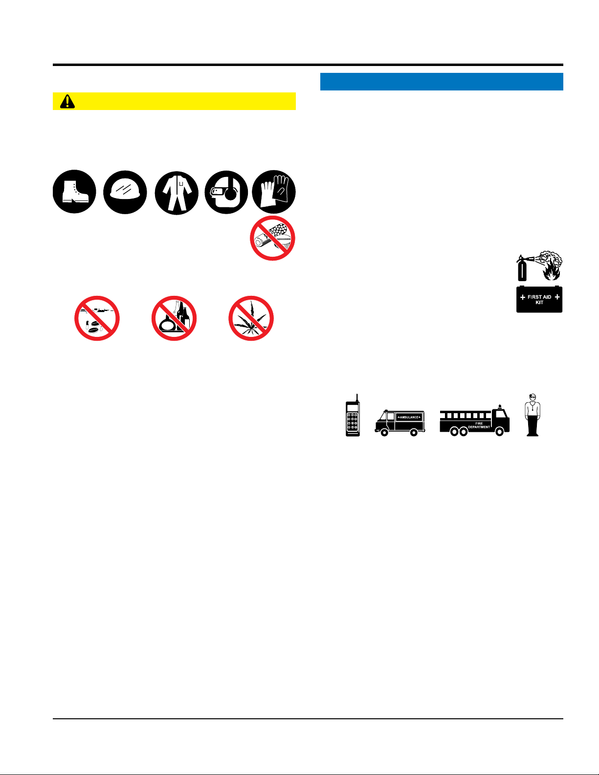
NEVER operate this equipment without proper protective
clothing, shatterproof glasses, respiratory protection,
hearing protection, steel-toed boots and other protective
devices required by the job or city and state regulations.
NEVER operate this equipment when not
feeling well due to fatigue, illness or when
under medication.
NEVER operate this equipment under the infl uence of
drugs or alcohol.
ALWAYS check the equipment for loosened threads or
bolts before starting.
DO NOT use the equipment for any purpose other than
its intended purposes or applications.
ALWAYS clear the work area of any debris, tools, etc.
that would constitute a hazard while the equipment is
in operation.
qualifi ed personnel 18 years of age and older.
safety decals when they become diffi cult read.
equipment modifi cation will void all warranties.
NEVER
to the equipment and/or injury to user may result.
ALWAYS know the location of the nearest
fi re extinguisher.
ALWAYS know the location of the nearest
fi rst aid kit.
ALWAYS know the location of the nearest phone or
a phone on the job site.
of the nearest ambulance, doctor and
emergency.
MVH508DZ PLATE COMPACTOR • OPERATION AND PARTS MANUAL — REV. #0 (04/04/14)— PAGE 7
Page 8
SAFETY INFORMATION
COMPACTOR SAFETY
ENGINE SAFETY
place hands or fingers inside engine
operate the engine with heat shields or
engine is hot. High pressure boiling water will gush out
of the radiator and severely scald any persons in the
remove the engine oil drain plug while the
engine is hot. Hot oil will gush out of the oil tank and
severely scald any persons in the general area of the
run engine without an air fi lter or with a dirty air
fi lter. Severe engine damage may occur. Service air fi lter
tip the engine to extreme angles during lifting as
it may cause oil to gravitate into the cylinder head, making
WARNING
DANGER
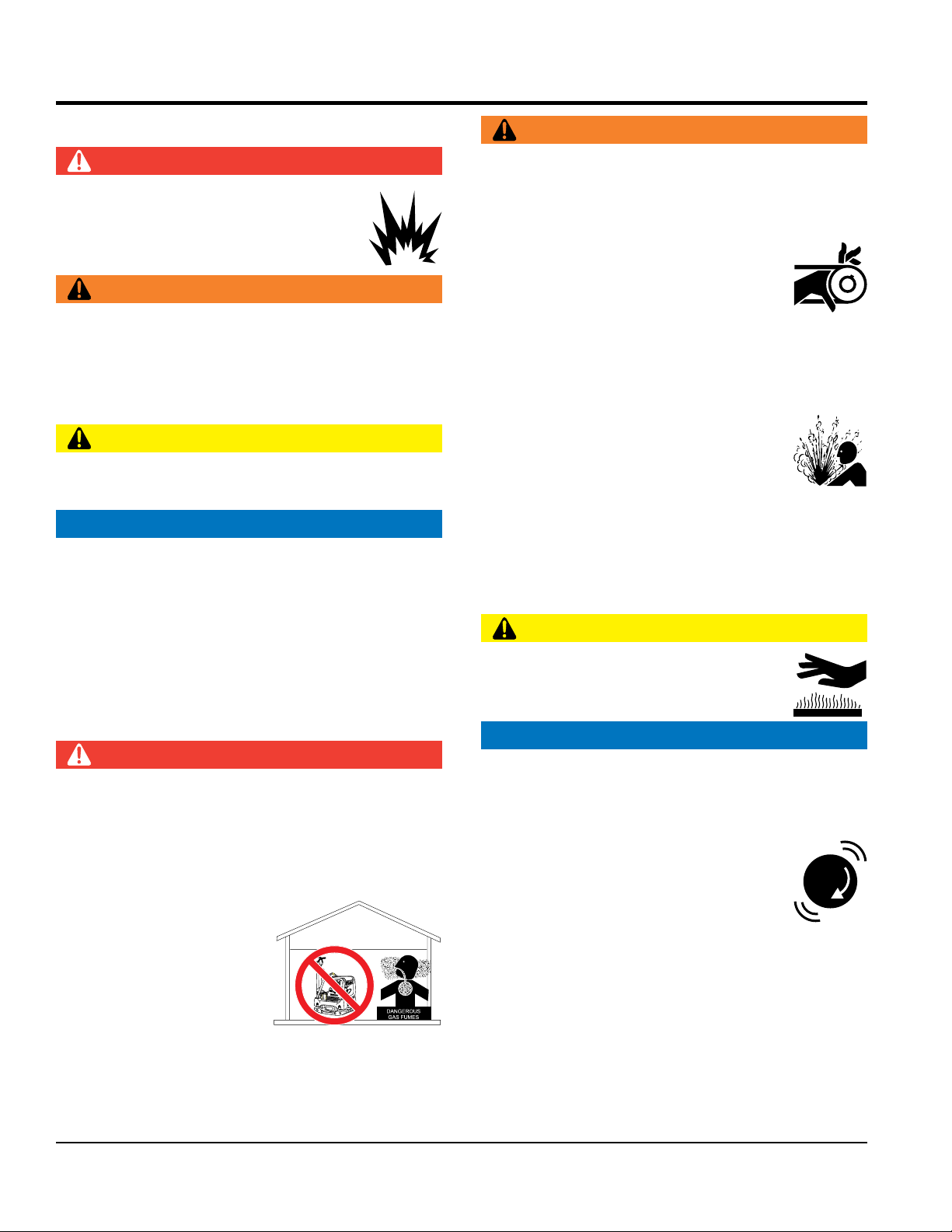
NEVER operate the equipment in an explosive
atmosphere or near combustible materials. An
explosion or fi re could result causing severe
bodily harm or even death.
WARNING
NEVER disconnect any emergency or safety devices.
These devices are intended for operator safety.
Disconnection of these devices can cause severe injury,
bodily harm or even death. Disconnection of any of these
devices will void all warranties.
CAUTION
NEVER lubricate components or attempt service on a
running machine.
NOTICE
ALWAYS keep the machine in proper running condition.
Fix damage to machine and replace any broken parts
immediately.
ALWAYS store equipment properly when it is not being
used. Equipment should be stored in a clean, dry location
out of the reach of children and unauthorized personnel.
DO NOT
compartment when engine is running.
NEVER
guards removed.
Keep fi ngers, hands hair and clothing away
from all moving parts to prevent injury.
DO NOT remove the radiator cap while the
general area of the compactor.
DO NOT remove the coolant drain plug
while the engine is hot. Hot coolant will
gush out of the coolant tank and severely
scald any persons in the general area of
the compactor.
DO NOT
compactor.
CAUTION
NEVER touch the hot exhaust manifold,
muffl er or cylinder. Allow these parts to cool
before servicing equipment.
DANGER
The engine fuel exhaust gases contain poisonous carbon
monoxide. This gas is colorless and odorless, and can
cause death if inhaled.
The engine of this equipment requires an adequate
free fl ow of cooling air. NEVER operate this equipment
in any enclosed or narrow
area where free fl ow of the
air is restricted. If the air
fl ow is restricted it will cause
injury to people and property
and serious damage to the
equipment or engine.
PAGE 8 — MVH508DZ PLATE COMPACTOR • OPERATION AND PARTS MANUAL — REV. #0 (04/04/14)
NOTICE
NEVER
frequently to prevent engine malfunction.
NEVER tamper with the factory settings
of the engine or engine governor. Damage
to the engine or equipment can result
if operating in speed ranges above the
maximum allowable.
NEVER
MVH-306
the engine start diffi cult.
Page 9
SAFETY INFORMATION
FUEL SAFETY
BATTERY SAFETY (ELECTRIC START ONLY)
drop the battery. There is a possibility that the
keep the battery charged. If the battery is not
charge battery if frozen. Battery can explode.
When frozen, warm the battery to at least 61°F (16°C).
recharge the battery in a well-ventilated
environment to avoid the risk of a dangerous concentration
If the battery liquid (dilute sulfuric acid) comes into
, rinse eyes immediately with plenty
of water and contact the nearest doctor or hospital to
NEGATIVE battery terminal
keep battery cables in good working condition.
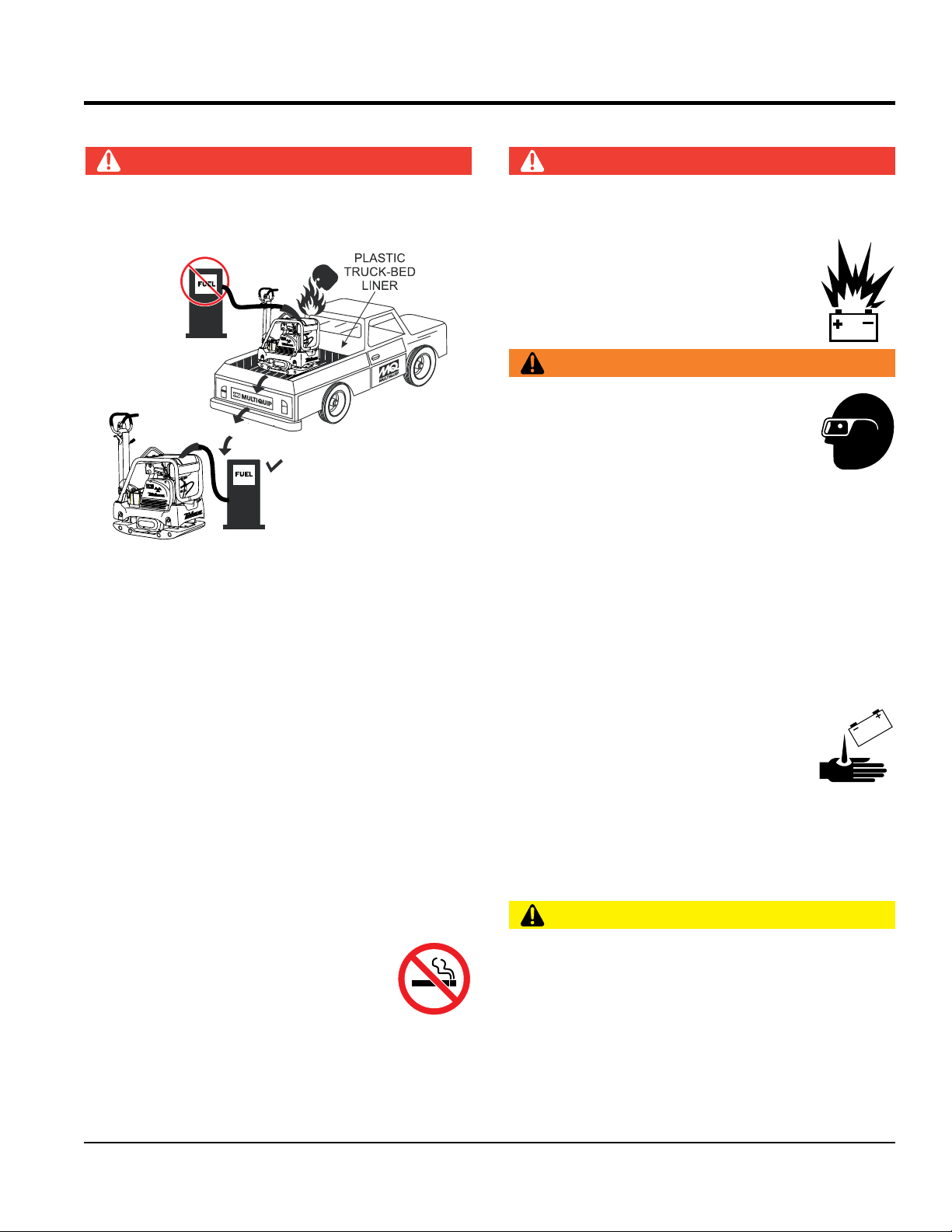
DO NOT add fuel to equipment if it is placed inside truck
bed with plastic liner. Possibility exists of explosion or
fi re due to static electricity.
DO NOT start the engine near spilled fuel or combustible
fl uids. Diesel fuel is extremely fl ammable and its vapors
can cause an explosion if ignited.
DANGER
MVH-306
MVH-306
DANGER
DO NOT
battery will explode.
DO NOT expose the battery to open fl ames,
sparks, cigarettes, etc. The battery contains
combustible gases and liquids. If these
gases and liquids come into contact with a
fl ame or spark, an explosion could occur.
WARNING
ALWAYS wear safety glasses when
handling the battery to avoid eye irritation.
The battery contains acids that can cause
injury to the eyes and skin.
Use well-insulated gloves when picking up
the battery.
ALWAYS
charged, combustible gas will build up.
DO NOT
ALWAYS refuel in a well-ventilated area, away from
sparks and open fl ames.
ALWAYS use extreme caution when working with
fl ammable liquids.
DO NOT fi ll the fuel tank while the engine is running
or hot.
DO NOT overfi ll tank, since spilled fuel could ignite if it
comes into contact with hot engine parts or sparks from
the ignition system.
Store fuel in appropriate containers, in well-ventilated
areas and away from sparks and fl ames.
NEVER use fuel as a cleaning agent.
DO NOT smoke around or near the
equipment. Fire or explosion could result
from fuel vapors or if fuel is spilled on a
hot engine.
ALWAYS
of combustible gases.
If the battery liquid (dilute sulfuric acid)
comes into contact with clothing or skin,
rinse skin or clothing immediately with
plenty of water.
contact with eyes
seek medical attention.
CAUTION
ALWAYS disconnect the
before performing service on the equipment.
ALWAYS
Repair or replace all worn cables.
MVH508DZ PLATE COMPACTOR • OPERATION AND PARTS MANUAL — REV. #0 (04/04/14)— PAGE 9
Page 10

TRANSPORTING SAFETY
CAUTION
ENVIRONMENTAL SAFETY/
Decommissioning is a controlled process used to safely
retire a piece of equipment that is no longer serviceable.
If the equipment poses an unacceptable and unrepairable
safety risk due to wear or damage or is no longer cost
effective to maintain (beyond life-cycle reliability) and is to
be decommissioned (demolition and dismantlement),be
sure to follow rules below:
When the life cycle of this equipment is over, remove
battery and bring to appropriate facility for lead
reclamation. Use safety precautions when handling
When the life cycle of this equipment is over, it is
recommended that the trowel frame and all other metal
Metal recycling involves the collection of metal from
discarded products and its transformation into raw
materials to use in manufacturing a new product.
Recyclers and manufacturers alike promote the process
of recycling metal. Using a metal recycling center
The diesel engine used in this equipment has been
designed to reduce harmful levels of carbon monoxide
(CO), hydrocarbons (HC) and nitrogen oxides (NOx)
This engine has been certifi ed to meet US EPA Evaporative
Attempting to modify or make adjustments to the engine
emission system by unauthorized personnel without proper
training could damage the equipment or create an unsafe
Additionally, modifying the fuel system may adversely affect
evaporative emissions, resulting in fi nes or other penalties.
The emission control label is an integral part of the emission
If a replacement emission label is needed, please contact
NEVER allow any person or animal to stand underneath
the equipment while lifting.
NOTICE
Before lifting, make sure that the equipment parts (hook
and vibration insulator) are not damaged and screws are
not loose or missing.
Always make sure crane or lifi tng device has been
properly secured to the lifting bail (hook) of the
equipment.
ALWAYS shutdown engine before transporting.
NEVER lift the equipment while the engine is running.
Tighten fuel tank cap securely and close fuel cock to
prevent fuel from spilling.
SAFETY INFORMATION
batteries that contain sulfuric acid.
parts be sent to a recycling center.
promotes energy cost savings.
EMISSIONS INFORMATION
NOTICE
Use adequate lifting cable (wire or rope) of suffi cient
strength.
Use one point suspension hook and lift straight
upwards.
DO NOT lift machine to unnecessary heights.
ALWAYS tie down equipment during transport by
securing the equipment with rope.
DECOMMISSIONING
NOTICE
DO NOT pour waste or oil directly onto the ground, down
a drain or into any water source.
Contact your country's Department of
Public Works or recycling agency in your
area and arrange for proper disposal of
any electrical components, waste or oil
associated with this equipment.
contained in diesel exhaust emissions.
emissions requirements in the installed confi guration.
condition.
Emission Control Label
system and is strictly controlled by regulations.
The label must remain with the engine for its entire life.
your authorized Kohler Engine Distributor.
PAGE 10 — MVH508DZ PLATE COMPACTOR • OPERATION AND PARTS MANUAL — REV. #0 (04/04/14)
Page 11

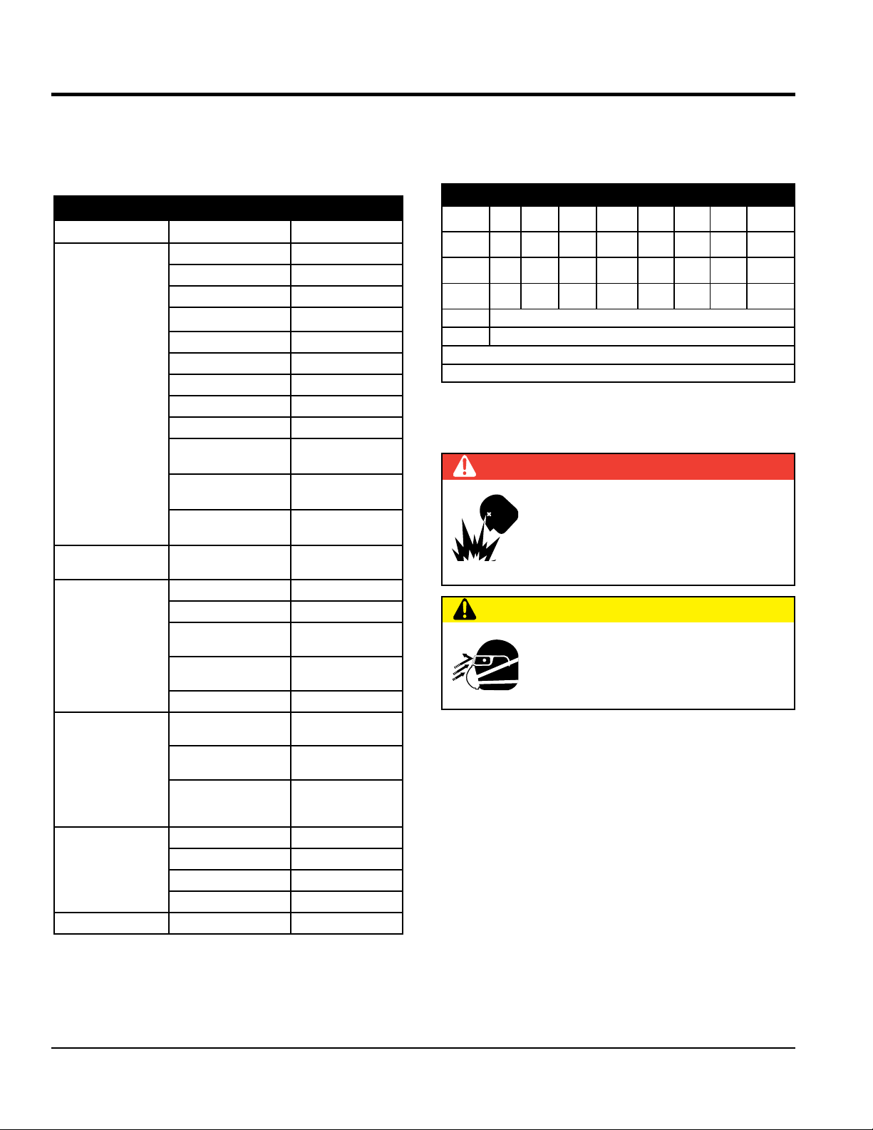
SPECIFICATIONS
Table 1. MVH508DZ Specifications
Centrifugal Force 14613 lbf (65 kN)
Vibration Frequency 4,150 vpm (70 Hz)
Maximum Traveling Speed 82 ft/min (25 m/min)
Plate Size (W x L) 25.59 x 35.43 in (650 x 900 mm)
Plate Size (W x L) with extension plates 31.5 x 35.43 in (800 x 900 mm)
Max. Forward Speed 82 ft./min (25 m/min)
Operating Weight 1157.42 lbs. (525 kg.)
Operating Weight with extension plates 1181.68 lbs. (536 kg.)
Table 2. Engine Specifications
Engine Make HATZ
Engine Model 1D81S-325
Engine Type Air-cooled, 4 Cycle Diesel Engine
Cylinder Bore X Stroke 3.94 in. x 3.35 in. (100 mm x 85 mm)
Displacement 40.7 cu-in (0.667 l)
Maximum Ouput 11.9 BHP (8.9 kW) @ 2500 RPM
Fuel Type Diesel
Oil Capacity 2 qts (1.9 liters)
Starting Method Recoil/Electric Start
Weight (Recoil Start) 213.8 lbs (97 Kg.)
Weight (Electric Start) 231.4 lbs (105 Kg.)
MVH508DZ PLATE COMPACTOR • OPERATION AND PARTS MANUAL — REV. #0 (04/04/14)— PAGE 11
Page 12
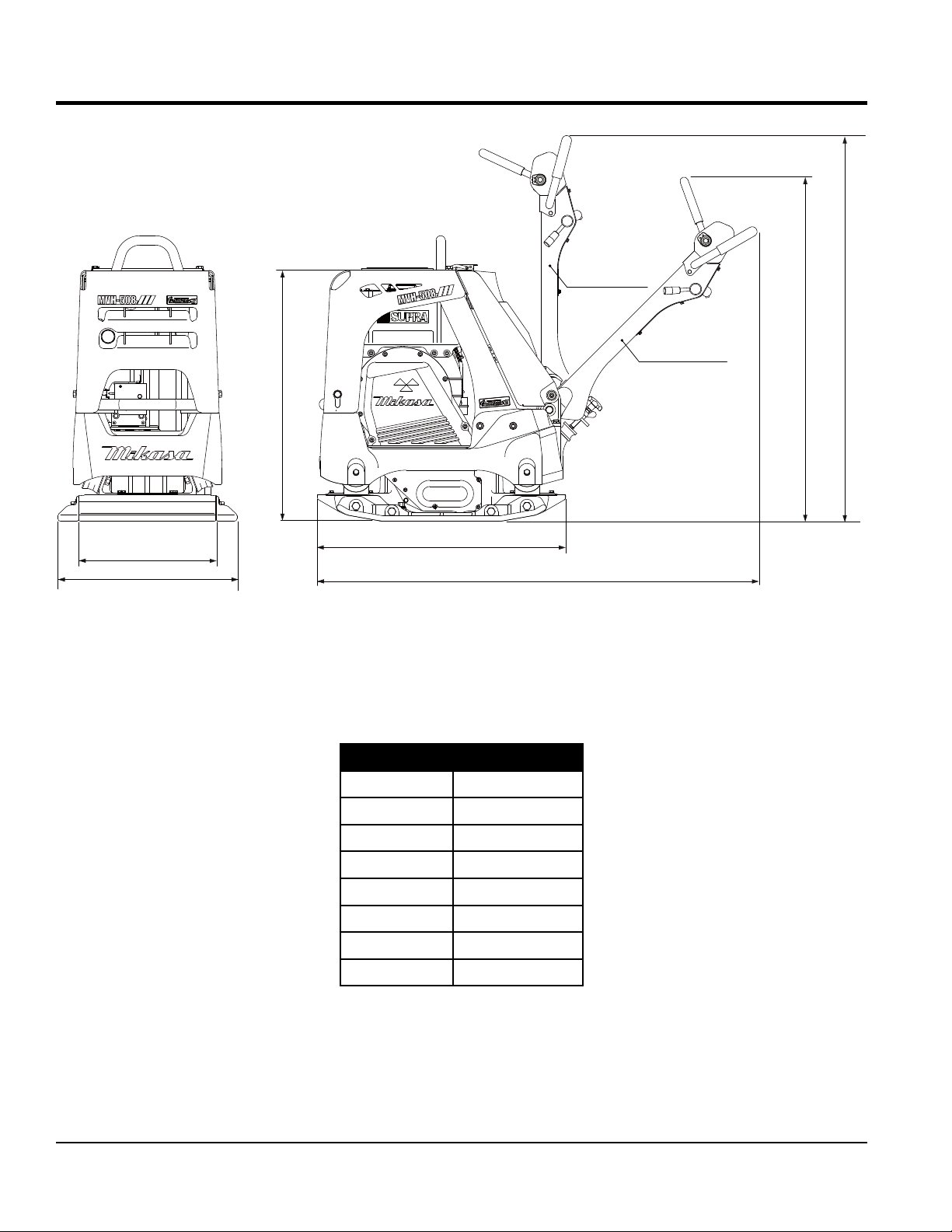
DIMENSIONS
Stored position
D
Working position
C
E
A
B
extension plate (option)
F
G
Figure 1. Dimensions
Table 3. Dimensions
REF. DES IN. (MM)
A 25.59 (650)
B 31.5 (800)
C 40.94 (1040)
D 47.64 (1210)
E 53.54 (1360)
F 35.43 (900)
G 63.00 (1600)
PAGE 12 — MVH508DZ PLATE COMPACTOR • OPERATION AND PARTS MANUAL — REV. #0 (04/04/14)
Page 13

GENERAL INFORMATION
DEFINITION OF PLATE COMPACTOR
The Mikasa MVH508DZ is a reversible plate compactor
designed for efficient compaction of sand, gravel and
cohesive soils. This plate compactor is a powerful
compacting tool capable of applying a tremendous force
in consecutive high frequency vibrations to a soil surface.
Its applications include compacting for road, embankments
and reservoirs as well as backfilling for gas pipelines, water
pipelines and cable installation work.
VIBRATORY PLATES
The vibratory plates of the compactor produce low
amplitude high frequency vibrations, designed to compact
granular soils and asphalt.
The resulting vibrations cause forward motion. The engine
and handle are vibration isolated from the vibrating plate.
FREQUENCY/SPEED
The compactor's vibrating plate produces a vibration
frequency of 4,150 VPM (vibrations per minute).
The travel speed of the compactor is approximately
82 ft/minute (25 meters/minute).
ENGINE
This plate compactor are equipped with a Hatz 1D81S
air cooled, 4-cycle diesel engine. The engine drives an
eccentric weight at a high speed to develop a compaction
force.
CONTROLS
Before starting the plate compactor identify and understand
the function of all the controls and components.
MVH508DZ PLATE COMPACTOR • OPERATION AND PARTS MANUAL — REV. #0 (04/04/14)— PAGE 13
Page 14
COMPONENTS
1
8
10
2
3
5
7
27
4
6
12
Neutral
Forward
9
11
(Stored position
13
11
17
16
14
(Working position)
Reverse
15
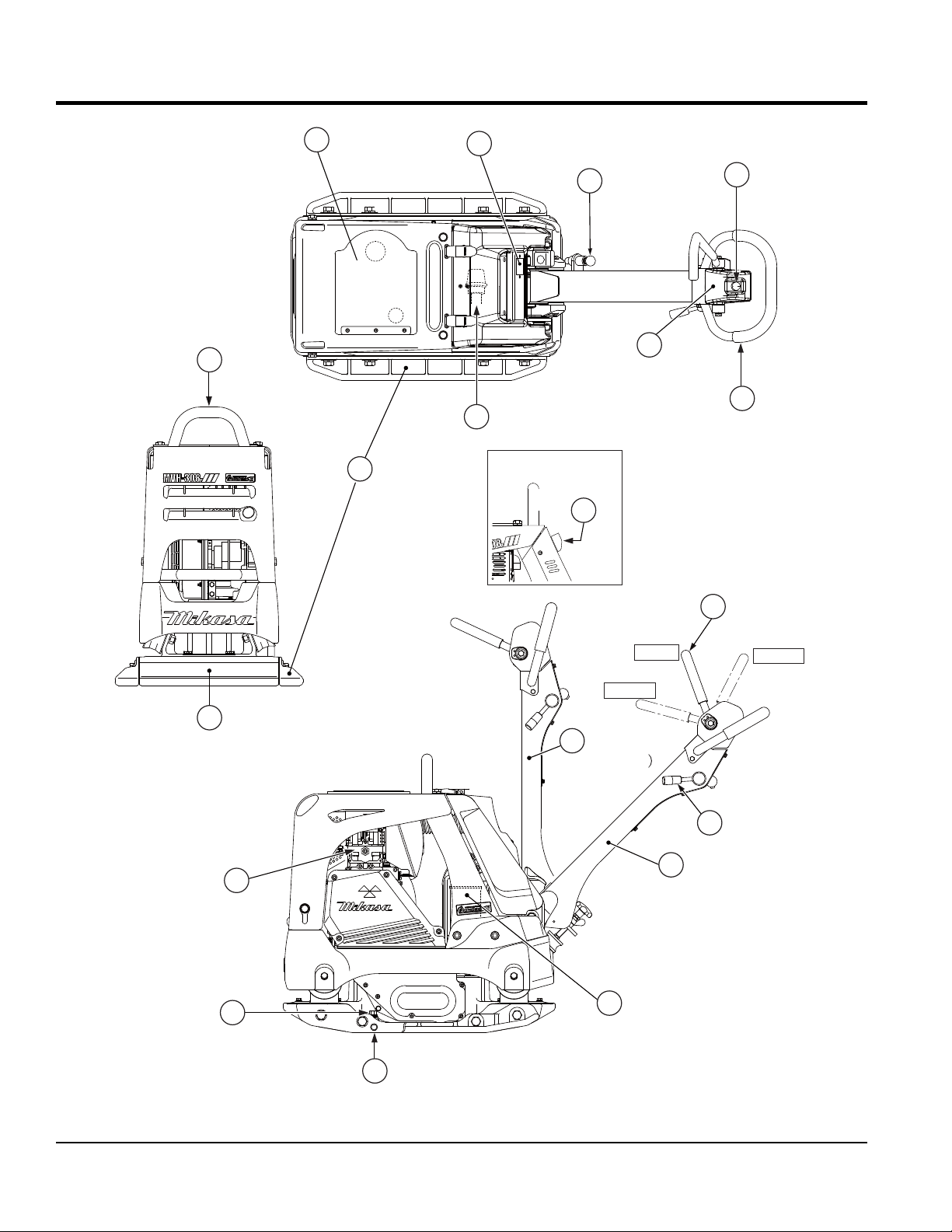
Figure 2. Plate Compactor Components
PAGE 14 — MVH508DZ PLATE COMPACTOR • OPERATION AND PARTS MANUAL — REV. #0 (04/04/14)
Page 15

COMPONENTS
Figure 2 shows the location of the basic controls and
components of the MVH508DZ Plate Compactor. The
function of each control is described below:
1. Rubber Cover — Lift this rubber cover to gain access
to the fuel tank.
2. Hour/Tachometer — Displays the cumulative time
that the machine has been in use. During operation it
displays the rpm reading. The tachometer also has a
battery checker that lights red when the charge is low.
3. Handle Bar Height Adjuster — Adjusts the handle
bar to the desired height by loosening the wing nut and
turning the grip clockwise to raise the handle bar and
counterclockwise to lower the handle bar.
4. Breather Plug — Allow pressure to escape to the air
in the form of a gas from heat.
5. Hydraulic Pump (Oil Reservoir) — Regulates
hydraulic oil flow produced by the direction of the
control lever.
6. Hand Grip — When operating the compactor, use this
hand grip to maneuver the compactor.
9. Vibrating Plate — A flat, open plate made of durable
cast iron construction used in the compacting of soil.
10. Extension Plate — Provides additional area of
vibration to the vibrating plate.
11. Handle Bar — When operating the compactor, this
handle is to be in the downward position. When the
compactor is to be stored, move the handle bar to
the upright position.
12. Direction Control Lever — Push the lever forward to
move compactor in a forward direction. Pull the lever
backwards to move compactor in backwards direction.
Placing the lever in the middle (midway) will cause the
compactor not to move (neutral).
Throttle Lever — Controls speed of the plate
13.
compactor. Place straight vertically to start, push fully
counterclockwise for full throttle and fully clockwise to
stop plate compactor.
14. Battery — Provides +12V DC to the electrical system.
15. Vibrator Oil Drain Plug — Used to drain vibrator oil
from the machine.
7. Cyclone Cleaner — Filters large dust particles to keep
air cleaner from getting clogged easily.
8. Lifting Bale — When lifting of the compactor is
required either by forklift, crane etc., tie rope or chain
around this lifting point.
16. Vibration Case Oil Filler — Used to add oil to the
vibration case.
17. Engine — This plate compactor uses a Hatz 1D81S
diesel engine. Refer to the owner’s manual for engine
information.
MVH508DZ PLATE COMPACTOR • OPERATION AND PARTS MANUAL — REV. #0 (04/04/14)— PAGE 15
Page 16
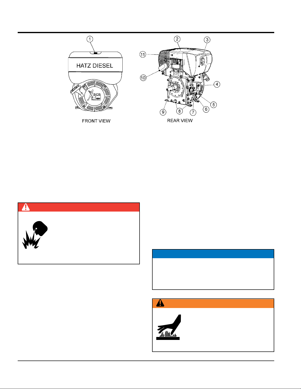
Figure 3. Engine Controls and Components
BASIC ENGINE
INITIAL SERVICING
The engine (Figure 3) must be checked for proper lubrication
and filled with fuel prior to operation. Refer to the manufacturer’s Engine manual for operating and servicing information.
1. Fuel Filler Cap/Fuel Tank — Pull this latch to add
diesel fuel to the tank. After refueling, always make
sure the fuel cap is latched properly. DO NOT over
fill. For additional information refer to engine owner’s
manual.
DANGER
.
Adding fuel to the tank should be done
only when the engine is stopped and has
had an opportunity to cool down. In the
event of a fuel spill, DO NOT attempt to
start the engine until the fuel residue has
been completely wiped up, and the area
surrounding the engine is dry.
2. Engine Lifting Straps/Cover — Remove the air
cleaner cover, then lift this cover (the one with decals
on it) to gain access to the engine lifting straps.
6. Engine Motor Mounts — Attach these engine mounts
to the pump frame. Tighten securely.
7. Oil Filter — Remove this bolt to gain access
(internal) to the engine oil filter. Service the oil filter
as recommended in the maintenance section of this
manual.
8. Oil Drain Plugs —There are two oil drain plugs, one
is underneath the flywheel, the other on the side of the
engine. Remove these plugs to drain engine oil from
the engine crankcase.
9. Crankshaft — Connect this shaft to the input of the
transmission.
10. Muffler — Used to reduce noise and emissions.
11. Nameplate — Contains information about the engine.
NOTICE
Operating the engine without an air filter, with a
damaged air filter, or a filter in need of replacement
will allow dirt to enter the engine, causing rapid engine
wear.
3. Air Cleaner/Cover — Prevents dirt and other debris
from entering the fuel system. Remove wing-nut on
side of air filter cover to gain access to filter element.
4. Speed Control Lever — This lever is connected to
the throttle control which is located on the side of the
engine compartment cover. Use this lever to control
engine speed.
5. Dipstick — Remove dipstick to determine if the engine
oil level is low. If low, add oil as specified.
PAGE 16 — MVH508DZ PLATE COMPACTOR • OPERATION AND PARTS MANUAL — REV. #0 (04/04/14)
WARNING
Engine components can generate
extreme heat. To prevent burns,
DO NOT touch these areas while the
engine is running or immediately after
operating. NEVER operate the engine
with the muffler removed.
Page 17
INSPECTION
BEFORE STARTING
1. Read all safety instructions at the beginning of manual.
2. Clean the compactor, removing dirt and dust,
particularly the engine cooling air inlet, carburetor and
air cleaner.
3. Check the air filter for dirt and dust. If air filter is dirty,
replace air filter with a new one as required.
4. Check carburetor for external dirt and dust. Clean with
dry compressed air.
5. Check fastening nuts and bolts for tightness.
ENGINE OIL CHECK
1. To check the engine oil level, place the compactor on
secure level ground with the engine stopped. If the oil
level is low, add oil (Grade CC or above).
2. Lubrication is done from the top of the engine (Figure 4).
DANGER
EXPLOSIVE FUEL!
Motor fuels are highly flammable and can
be dangerous if mishandled. DO NOT
smoke while refueling. DO NOT attempt
to refuel the compactor if the engine is
hot or running!
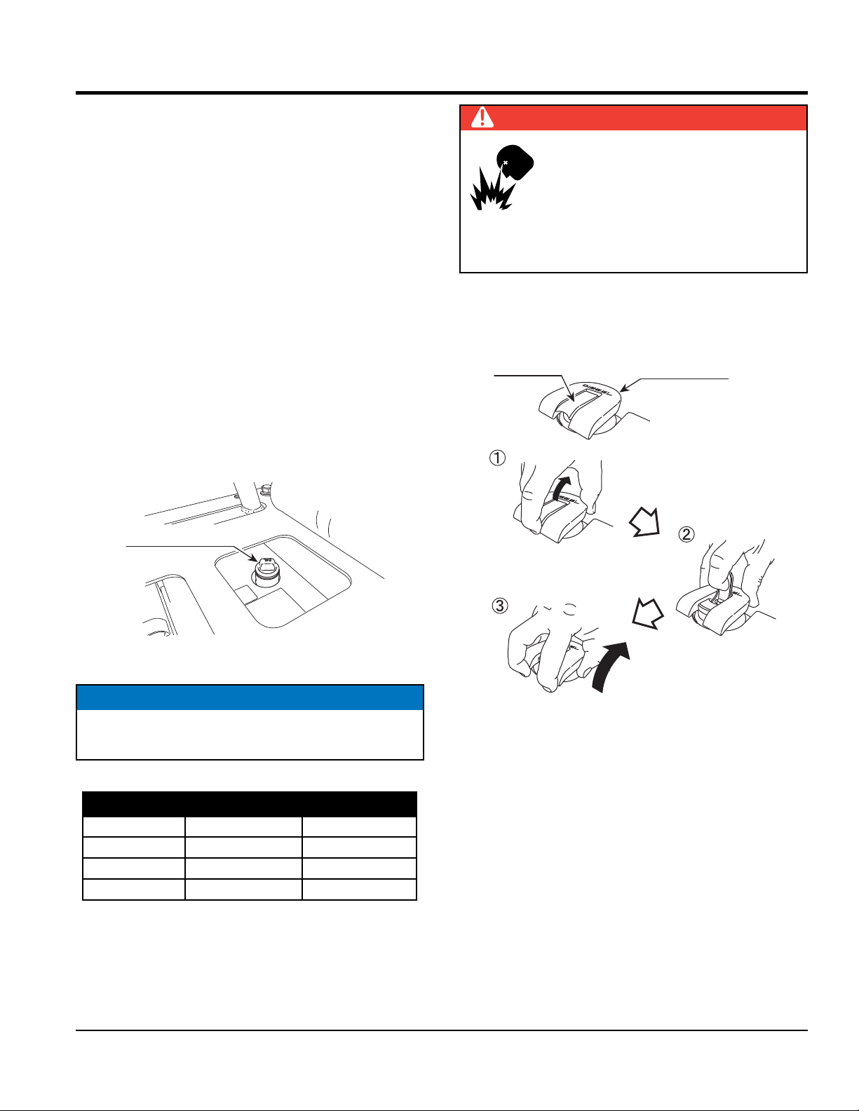
FUEL CHECK
1. The fuel tank cap is equipped with a lock lever. Unlock
the lever before opening cap (Figure 5).
Lock lever
Fuel tank cap
Oil inlet at the top
Figure 4. Adding Engine Oil
NOTICE
Pour oil slowly from the top. Oil might overflow if large
amount of oil is poured right away.
Table 4. Oil Type
Season Temperature Oil Type
Summer 25°C or Higher SAE 10W-30
Spring/Fall 25°C~10°C SAE 10W-30/20
Winter 0°C or Lower SAE 10W-10
Put your finger at the lock lever
to pull it up towards you.
Unlock the lock lever.
Put your fingers to the tabs at
the two locations of the tank
cap to pull up towards you.
Figure 5. Unlocking Fuel Cap Lever
1. Visually inspect to see if fuel level is low. If fuel is low,
replenish with unleaded fuel. Fuel inlet is located under
the rubber cover at the front cover top portion.
2. When refueling, be sure to use a strainer for filtration.
DO NOT top-off fuel. Wipe up any spilled fuel
immediately.
MVH508DZ PLATE COMPACTOR • OPERATION AND PARTS MANUAL — REV. #0 (04/04/14)— PAGE 17
Page 18
MISSING RUBBER
INSPECTION
CORRECT V-BELT
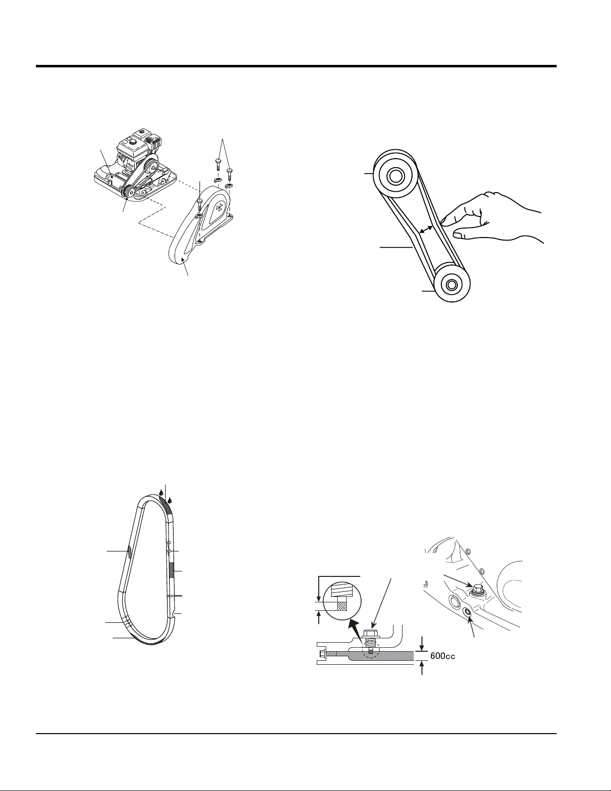
V-BELT COVER REMOVAL
To inspect the V-belt, remove the three bolts that secure
the belt cover to the frame as shown in Figure 6.
REMOVE
VIBRATOR
REMOVE
V-BELT
Mikasa
V-BELT COVER
Figure 6. V-Belt Cover Removal
V-BELT INSPECTION
Visually examine the V-belt (Figure 7) and determine if it
is full of tiny cracks, frayed, has pieces of rubber missing,
is peeling or otherwise damaged.
Also, examine the belt and determine if it is oil soaked or
"glazed " (hard shiny appearance on the sides of the belt).
Either of these two conditions can cause the belt to run hot,
which can weaken it and increase the danger of it breaking.
If the V-belt exhibits any of the referenced wear conditions
replace the V-belt immediately.
OIL SOAKED
V-BELT TENSION
The V-belt tension is proper if the V-belt bends 10 to 15 mm
(Figure 8) when depressed with finger at midway between
the clutch and vibrator pulleys.
CLUTCH
PULLEY
V-BELT
VIBRATOR
PULLEY
Figure 8. V-Belt Tension
TENSION 10-15 MM
WHEN DEPRESSED
AS SHOWN.
VIBRATOR OIL CHECK
1. Place the plate compactor horizontally on a flat surface.
Make sure the compactor is level when checking the
oil in the vibrator assembly.
2. Check vibrator oil level by removing the oil plug (vibrator
oil gauge) as shown in Figure 9. Clean the oil gauge
and re-thread back in. Remove the oil gauge again and
confirm oil level does not exceed the cross hash of the
oil plug. DO NOT OVERFILL!
3. The vibrator holds approximately 20.3 oz. (600 cc).
IMPORTANT, if oil is required, replace using only SAE
10W-30 motor oil.
GLAZED
CRACKS
SIDEWALL
WEAR
CORD FAILURE
WORN BACK
COVER
BROKEN
Effective
Oil gauge
(19mm wrench)
Drain plug
(14mm wrench)
Figure 7. Drive Belt Inspection
Figure 9. Vibrator Oil Check
PAGE 18 — MVH508DZ PLATE COMPACTOR • OPERATION AND PARTS MANUAL — REV. #0 (04/04/14)
Page 19
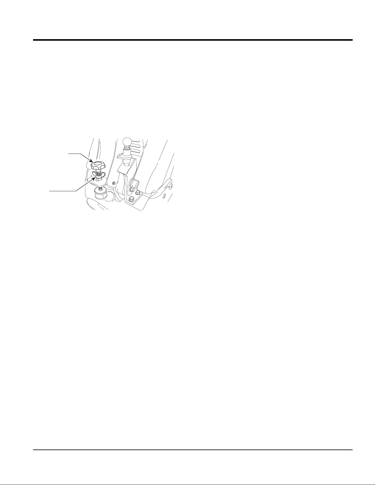
HANDLE BAR
The height of the handle bar can be adjusted for ease of
use. Adjust the handle height as follows. Refer to Figure 10.
1. Loosen the wing nut.
2. Turn the grip clockwise to raise the handle or
counterclockwise to lower the handle.
3. When the handle bar is raised to the desired height,
tighten the wing nut.
Grip
Wing nut
INSPECTION
Figure 10. Handle Height Adjustment
MVH508DZ PLATE COMPACTOR • OPERATION AND PARTS MANUAL — REV. #0 (04/04/14)— PAGE 19
Page 20
STARTUP
CAUTION
DO NOT attempt to operate the compactor
until the Safety, General Information and
Inspection sections of this manual have
been read and thoroughly understood.
This section is intended to assist the operator with the
initial startup of the compactor. It is extremely important
that this section be read carefully before attempting to use
the compactor in the field.
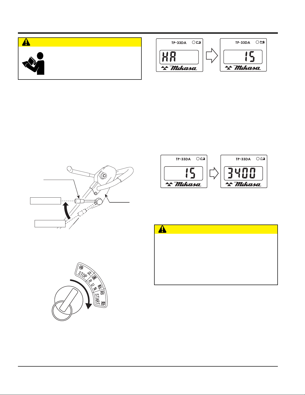
STARTING THE ENGINE
Electric Start
1. Insert the key to the key switch.
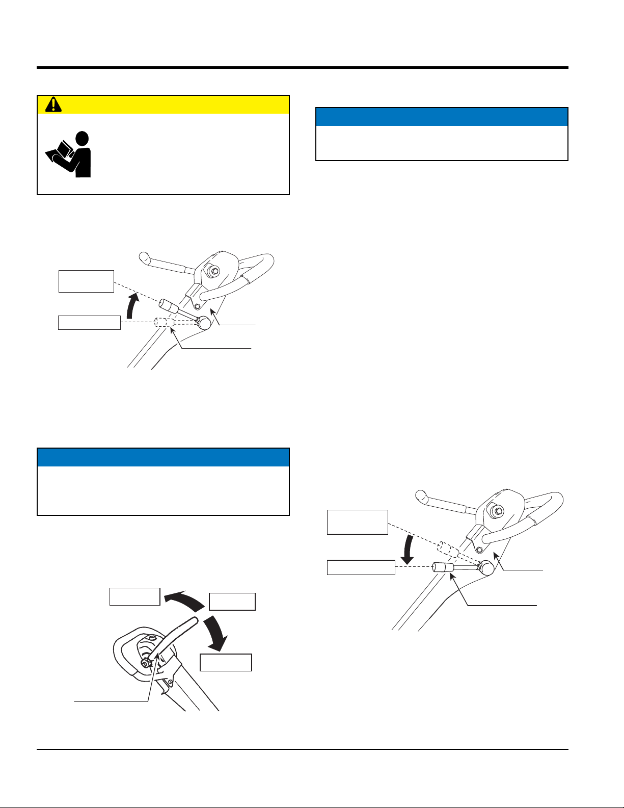
2. Move the throttle lever (Figure 11) to the idle position.
Throttle lever
ENGINE TACH
&HOUR
ENGINE TACH
&HOUR
DIESEL
"HA" is displayed at the operat ion position, then
immediately it will change to "Cumulative time".
METER
DIESEL
METER
HRS
Figure 13. Hour Tachometer (Cumulative Time)
5. Turn the key further to the "Start" position to start the
engine. When the engine starts, let go of the key. When
the engine revolution increases, the buzzer stops.
6. When the engine is in operation, the Hour Tachometer
display will show the "rotation number" (Figure 14).
Cumulative time
ENGINE TACH
&HOUR
DIESEL
METER
HRS
Rotation number
ENGINE TACH
&HOUR
DIESEL
METER
RPM
Idle position
Handle
Stop position
Figure 11. Throttle Lever (Idle Position)
3. Turn the key to the "Run" position (Figure 12). The
buzzer sounds.
Figure 12. Key Positions
4. After "HA" is displayed on the hour tachometer, the
display will change immediately to "cumulative time"
(Figure 13).
Figure 14. Hour Tachometer (Rotation Number)
7. After the engine has started, warm up the engine at low
speed for 2 to 3 minutes, especially in cold weather.
CAUTION
When the engine does not start, do not run the cell
motor continuously for more than 5 seconds. Move
the key back to the "Run" position then wait about 10
seconds to restart.
While the engine is running, never turn the key switch
to the "Start" position.
PAGE 20 — MVH508DZ PLATE COMPACTOR • OPERATION AND PARTS MANUAL — REV. #0 (04/04/14)
Page 21
Recoil Start
1. Insert the key to the key switch.
2. Move the throttle lever (Figure 11) to the idle position.
3. Turn the key to the "Run" position (Figure 12). The
buzzer sounds.
4. After "HA" is displayed on the hour tachometer, the
display will change immediately to "cumulative time"
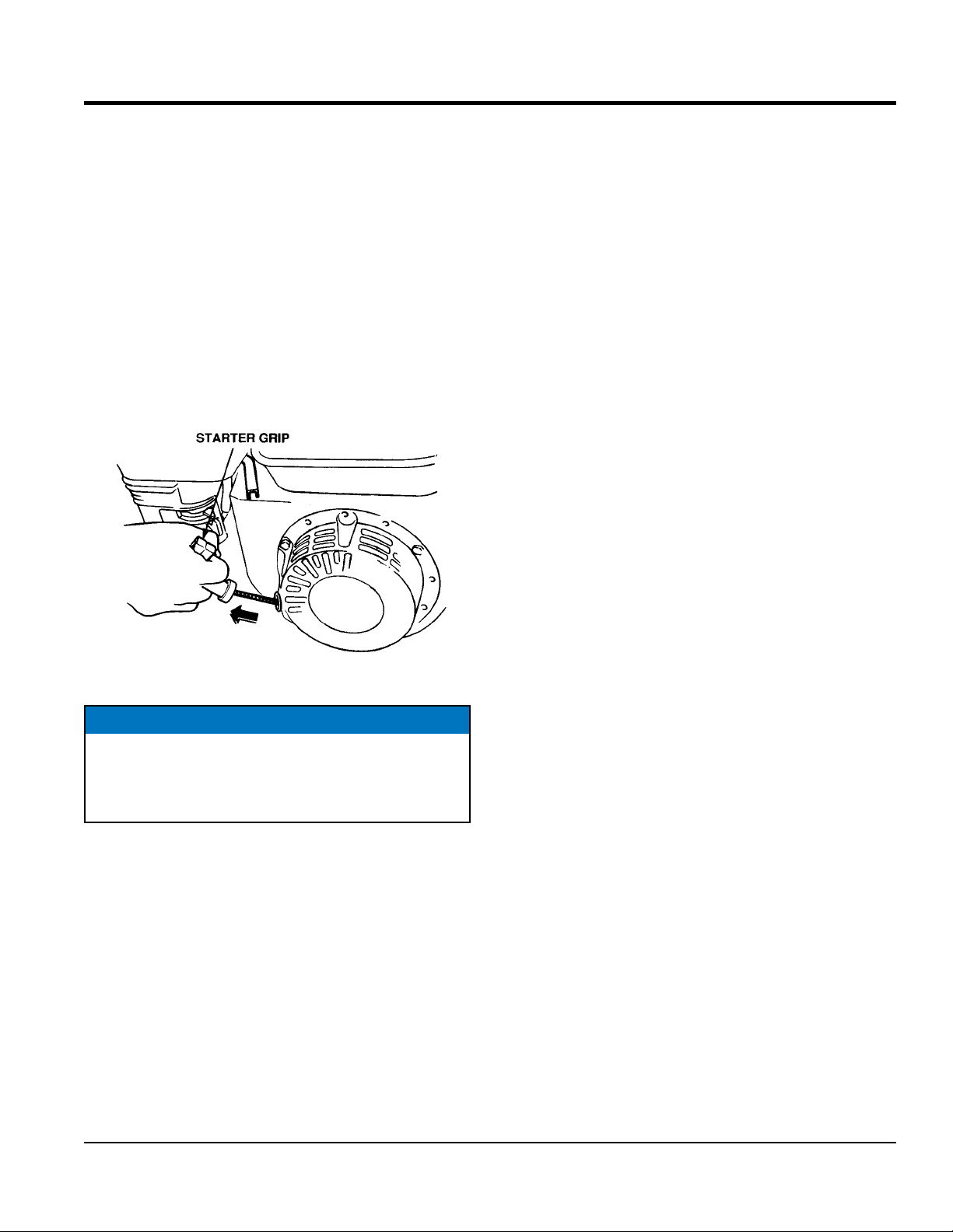
5. Grasp the starter grip (Figure 15) and slowly pull it
out. The resistance becomes the hardest at a certain
position, corresponding the compression point. Rewind
the rope a little from that point and pull out sharply.
STARTUP
Figure 15. Starter Grip
NOTICE
DO NOT pull the starter rope all the way to the end.
DO NOT release the starter rope after pulling. Allow it
to rewind as slow as possible.
6. When engine starts, release the starter grip and allow
the rope to recoil.
7. After the engine has started, warm up the engine at low
speed for 2 to 3 minutes, especially in cold weather.
8. Before the compactor is placed in to operation, run the
engine for several minutes. Check for fuel leaks, and
noises that would associate with a loose component.
MVH508DZ PLATE COMPACTOR • OPERATION AND PARTS MANUAL — REV. #0 (04/04/14)— PAGE 21
Page 22
OPERATION
OPERATION
CAUTION
ALWAYS follow all safety rules in the safety
section of this manual before operating
compactor. Keep work area clear of debris
and other objects that could cause bodily
injury or damage to the compactor.
1. Once the engine has started, move the engine throttle
lever quickly to the operation position (Figure 16).
Operation
position
Idle position
Throttle lever
Figure 16. Throttle Lever (Operation Position)
2. With the throttle lever in the run position, the engine
speed should be around 2,300 RPM, therefore
engaging the centrifugal clutch.
NOTICE
ALWAYS move the throttle lever quickly without
hesitation, because increasing the engine speed slowly
causes the clutch to slip.
3. Using the direction control lever, move the machine
backward or forward (Figure 17). When the direction
control lever is pushed forward, the machine moves
forward. When pulled backward, the machine moves
backward.
Reverse
Handle
Neutral
4. When the direction control lever is the neutral position,
the machine vibrates staying at the same location
NOTICE
NEVER stop the engine suddenly while working at
high speeds.
5. Compactor traveling speed may drop on soils which
contain clay, however there may be cases where
traveling speed drops because the compaction plate
does not leave the ground surface easily due to the
composition of the soil. To rectify this problem do the
following:
• Check the bottom plate to see if clay or equivalent
material has been lodge in the plate mechanism. If so,
wash with water and remove.
• Remember the compactor does not work as efficiently
on clay or soils that have a high moisture content level.
• If the soil has a high moisture level, dry soil to
appropriate moisture content level or carry out
compaction twice.
STOPPING THE ENGINE
Normal Shutdown
1. Move the throttle lever to the idle position (Figure 18)
and run the engine for three minutes at low speed.
Operation
position
Idle position
Throttle lever
Handle
Forward
Direction
control lever
Figure 17. Direction Control Lever
Figure 18. Throttle Lever (Idle)
PAGE 22 — MVH508DZ PLATE COMPACTOR • OPERATION AND PARTS MANUAL — REV. #0 (04/04/14)
Page 23
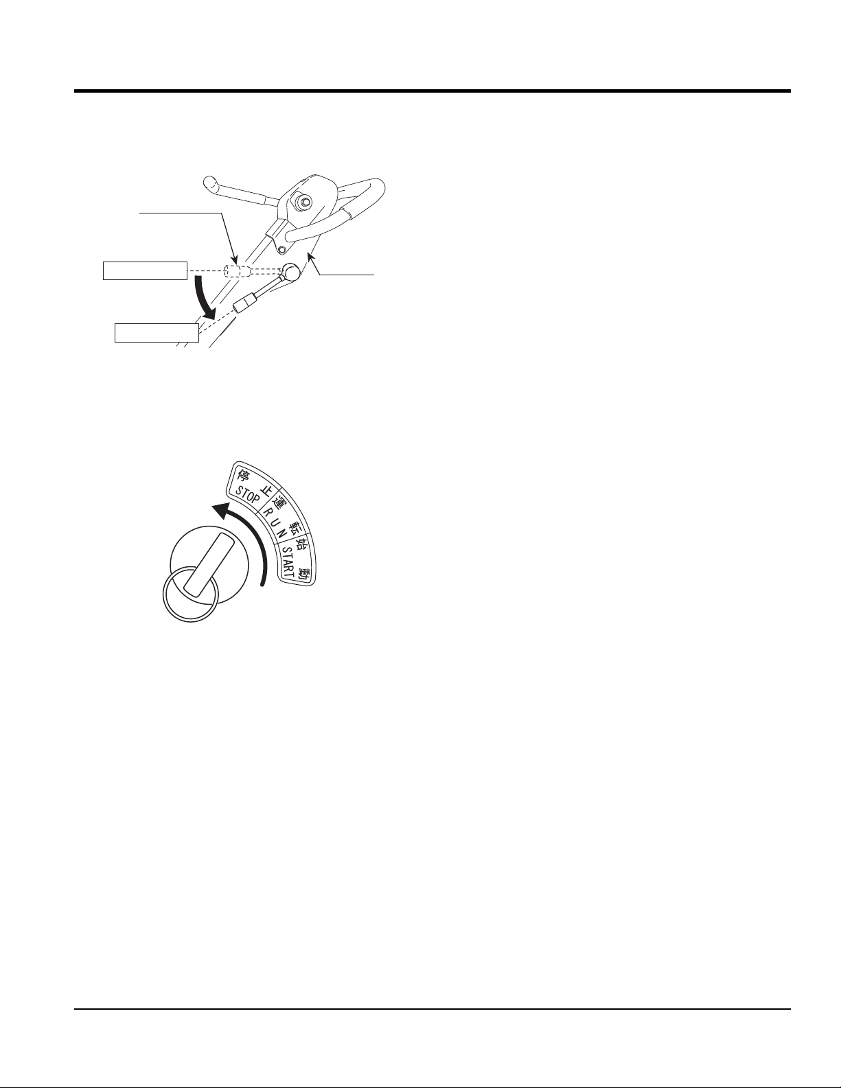
2. Move the throttle lever (Figure 19) to the "Stop" position
to stop the engine. The buzzer will sound.
Throttle lever
OPERATION
Idle position
Stop position
Figure 19. Throttle Lever (Stop Position)
Handle
3. Turn the key to the "Stop" position (Figure 20). The
buzzer will stop.
Figure 20. Key Switch (Stop)
Emergency Shutdown
1. Move the throttle lever quickly to the IDLE position,
and turn the key to the "Stop" position.
MVH508DZ PLATE COMPACTOR • OPERATION AND PARTS MANUAL — REV. #0 (04/04/14)— PAGE 23
Page 24
MAINTENANCE
GENERAL MAINTENANCE
General maintenance practices are crucial to the
performance and longevity of your compactor. This
equipment requires routine cleaning, inspection and
lubrication. Refer to Table 5 and Table 6 for scheduled
engine and compactor maintenance.
The following maintenance procedures can prevent serious
compactor damage or malfunctioning.
NOTICE
Refer to HATZ engine manual supplied with your
compactor for more detailed engine maintenance and
troubleshooting.
CAUTION
ALWAYS allow the engine to cool before
servicing. NEVER attempt any maintenance
work on a hot engine.
General Cleanliness
Clean the compactor daily. Remove all dust and debris
buildup (mud, clay etc.). If the compactor is steam-cleaned,
ensure that lubrication is accomplished AFTER steam
cleaning.
NOTICE
Inspection and other services should always be carried
out on hard and level ground with the engine shut down.
NOTICE
The inspection intervals listed in the maintenance tables
are for operation under normal conditions. Adjust your
inspection intervals based on the number hours plate
compactor is in use, and particular working conditions.
CAUTION
ALWAYS disconnect the spark plug wire from the spark
plug and secure away from the engine before performing
maintenance or adjustments on the machine.
WARNING
Some maintenance procedures
may require the engine to be run.
Ensure that the maintenance area is
well ventilated. Fuel engine exhaust
contains poisonous carbon monoxide
gas that can cause unconsciousness
and may result in DEATH.
PAGE 24 — MVH508DZ PLATE COMPACTOR • OPERATION AND PARTS MANUAL — REV. #0 (04/04/14)
Page 25

To make sure your plate compactor is always in good
working condition before using, carry out the maintenance
inspection in accordance with Table 5 and Table 6.
ENGINE MAINTENANCE
Perform engine maintenance as listed in Table 5.
Table 5. Engine Maintenance Schedule
MAINTENANCE
First
Description (3) Operation Before
Engine Oil
Air Cleaner
All Nuts and
Bolts
Spark Plug
Cooling Fins CHECK X
Spark Arrester CLEAN X
Fuel Tank CLEAN X
Fuel Filter CHECK X
Idle Speed CHECK-ADJUST X (2)
Valve Clearance CHECK-ADJUST X (2)
Fuel lines CHECK Every 2 years (replace if necessary) (2)
CHECK X
CHANGE X
CHECK X
CHANGE X (1)
Retighten If
Necessary
CHECK-CLEAN X
REPLACE X
X
Month or
10 hrs
Every 3
Months or
25 hrs
Every 6
Months or
50 hrs
Every
Year or
100 hrs
Every 2
Years or
200 hrs
1. Service more frequently when used in DUSTY areas.
2. These items should be serviced by your service dealer, unless you have the proper tools and are mechanically proficient.
Refer to the Hatz Shop Manual for service procedures.
3. For commercial use, log hours of operation to determine proper maintenance intervals.
MVH508DZ PLATE COMPACTOR • OPERATION AND PARTS MANUAL — REV. #0 (04/04/14)— PAGE 25
Page 26
MAINTENANCE
MACHINE INSPECTION
Perform machine inspection as listed in Table 6.
Table 6. Machine Inspection
Interval Check Solution
Machine Clean if necessary.
Fuel Tank For Leaks Repair fuel leaks.
Fuel System for Leaks Repair fuel leaks.
Engine Oil Add oil if necessary.
Vibrator Oil Add oil if necessary.
Air Cleaner Element Clean/Replace
Daily Before Starting
Every 20 Hours Engine Oil/Oil Filter
Every 100 Hours
Every 200 hours
Every 300 hours
Every 2 years Fuel Lines Replace
Guard Frame Inspect/deformations
Shock Absorber Replace if damaged.
Hydraulic pump Check/Repair Leaks
Hydraulic Pipe System
Direction Control Lever
Duct Hose
Engine Oil Change
Engine Oil Filter Wash
Vibrator Oil
Hydraulic Oil
Battery Terminal Clean
V-Belt
Clutch
Engine Bolts
Vibrator Oil Change
Fuel Filter Change
Hydraulic Oil Change
Engine Oil Filter Change
Check/Repair leaks,
Inspect for wear
Check bolts/nuts,
Inspect for wear
Check for crack/
damage
Replace only after
first 20 hrs.
Check oil level.
Check for leaks/dirt.
Check oil level.
Check for leaks.
Inspect, replace if
damaged or worn.
Inspect, replace if not
working properly.
Replace bolts
if deformed or
elongated.
TIGHTENING TORQUE
Reference Table 7 below (Tightening Torque ), for retightening of nuts and bolts.
Table 7. Tightening Torque (in. kg/cm Diameter)
Material
Bolt threads used with this machine are all right handed
Material and quality of material is marked on each bolt, and screw.
6mm 8mm 10mm 12mm 14mm 16mm 18mm 20mm
4T 70 150 300 500 750 1,100 1,400 2,000
6-8T 100 250 500 800 1,300 2,000 2,700 3,800
11T 150 400 800 1,200 2,000 2,900 4,200 5,600
*
100 (6mm) 300 ~ 350 (8mm) 650 ~ 700 (10mm)
**
In case counter-part is of aluminum
ENGINE AIR CLEANER
DANGER
DO NOT use gasoline or low flash point
solvents for cleaning the air cleaner. The
possibility exists of fire or explosion which
can cause damage to the equipment and
severe bodily harm or even DEATH!
CAUTION
Wear protective equipment such as
approved safety glasses or face shields
and dust masks or respirators when
cleaning air filters with compressed air.
This engine is equipped with a replaceable, high-density
paper air cleaner element. See (Figure 21) for air cleaner
components.
1. Remove the air cleaner cover and foam filter element.
2. Tap the paper filter element several times on a hard
surface to remove dirt, or blow compressed air not
exceeding 30 psi (207 kPa, 2.1 kgf/cm2) through the
filter element from the inside out. NEVER brush off
dirt. Brushing will force dirt into the fibers. Replace the
paper filter element if it is excessively dirty.
PAGE 26 — MVH508DZ PLATE COMPACTOR • OPERATION AND PARTS MANUAL — REV. #0 (04/04/14)
Page 27
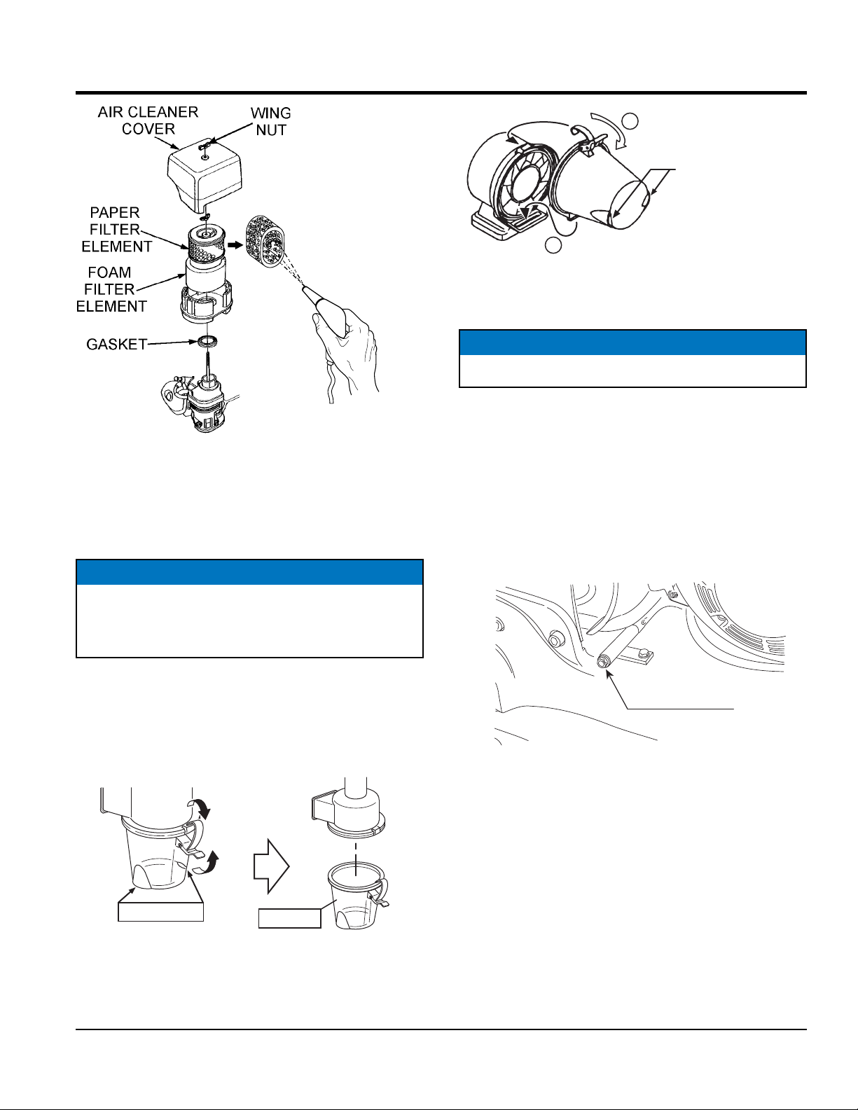
BLOW COMPRESSED
AIR FROM THE
INSIDE OUT
Figure 21. Engine Air Cleaner
3. Clean foam element in warm, soapy water or
nonflammable solvent. Rinse and dry thoroughly. Dip
the element in clean engine oil and completely squeeze
out the excess oil from the element before installing.
NOTICE
MAINTENANCE
2
Lock
Dust exhaust
1
Figure 23. Latching Dust Pot
ENGINE OIL
NOTICE
Drain the engine oil when the oil is warm.
1. Remove the oil drain bolt (Figure 24). and sealing
washer and allow the oil to drain into a suitable
container.
2. Replace engine oil with recommended type oil as listed
in Table 4. For engine oil capacity, see Table 2 (Engine
Specifications). DO NOT overfill.
3. Reinstall drain bolt with sealing washer and tighten
securely.
Operating the engine with loose or damaged air cleaner
components could allow unfiltered air into the engine
causing premature wear and failure.
CYCLONE CLEANER
Always clean the dust pot. A clogged dust pot reduces
cyclone effect with cleaner element wearing easily.
1. Unlatch and remove dust pot (Figure 22).
Latch
Dust exhaust
Figure 22. Unlatching Dust Pot
2. Clean dust pot with water and neutral detergent.
Dust pot
Engine oil drain
(Drain bolt)
Figure 24. Draining Engine Oil
3. Return dust pot to air cleaner and latch securely.
MVH508DZ PLATE COMPACTOR • OPERATION AND PARTS MANUAL — REV. #0 (04/04/14)— PAGE 27
Page 28
MAINTENANCE
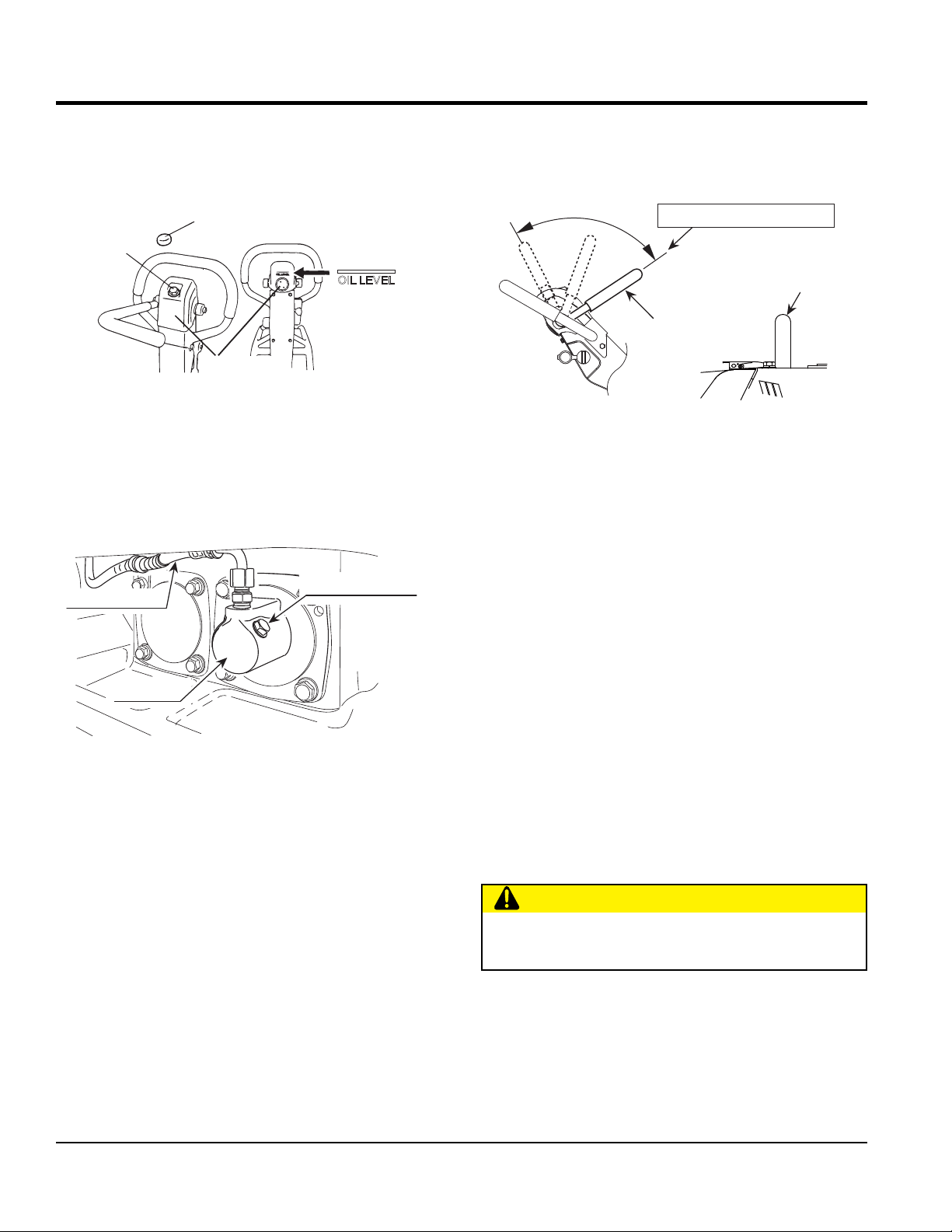
HYDRAULIC OIL
1. With the handle in vertical position, remove the plug
cap from the hydraulic pump (Figure 25).
Plug cap
Breather
plug
OIL LEVEL
Hydraulic
pump
Figure 25. Removing Plug/Breather Cap
2. Remove the breather plug with a 24 mm wrench at the
top of the hydraulic pump.
3. Remove the hydraulic hose connected to the cylinder
on the vibrator side (Figure 26).
Air releasing plug
Hydraulic hose
7. With the direction control lever at the forward-most
position, secure the guard frame with a rope to
immobilize (Figure 27).
Forward-most position
Guard frame
Direction
control lever
Figure 27. Direction Control Lever
(Forward Position)
8. Pour hydraulic oil (550cc) to the hydraulic pump
breather plug attachment hole (Figure 25).
9. Remove the air releasing plug of vibrator cylinder. Oil
will then come out from the air releasing plug. After air
bubbles stop coming out, reattach the plug. Tighten
securely (Figure 26).
Cylinder
Figure 26. Removing Hydraulic Hose
4. Set the run lever to reverse.
5. Drain the hydraulic oil from the pump.
6. After the oil is drained, attach the hydraulic hose again
to the cylinder on the vibrator side.
10. Release the direction control lever and move the lever
forward and reverse several times (until no air bubbles
are seen). Keep the lever at the forward position for
10 seconds every time. (Because the check valve is
opened at the maximum forward position and air bubble
will come out from the oil tank of the hydraulic pump).
11. In case the air bleeding is insufficient, repeat steps 9
and 10.
12. Attach the hydraulic pump breather plug and put on
the plug cap. After making sure the hydraulic oil in the
pump is at OIL LEVEL, attach the breather plug.
CAUTION
DO NOT exceed OIL LEVEL of hydraulic oil. If the level
is higher, oil will burst out from the breather plug.
PAGE 28 — MVH508DZ PLATE COMPACTOR • OPERATION AND PARTS MANUAL — REV. #0 (04/04/14)
Page 29
MAINTENANCE
GAP
4MM SCREW (3)
SCREEN
BRUSH
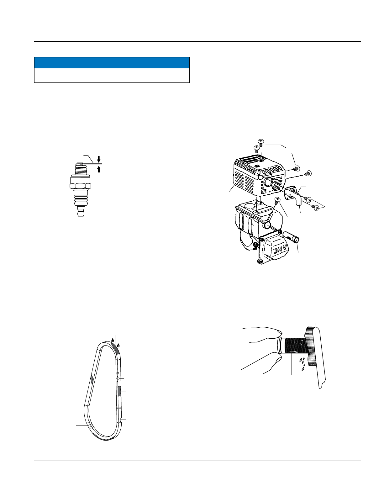
SPARK PLUG
NOTICE
NEVER use a spark plug of incorrect heat range.
1. Remove and clean spark plug (Figure 28) with a wire
brush if it is to be reused. Discard spark plug if the
insulator is cracked or chipped.
2. Using a feeler gauge adjust spark plug gap to
0.028 ~0.031 inch (0.7~0.8 mm).
3. Thread spark plug into cylinder hole by hand to prevent
cross-threading, then tighten securely.
.028 - .031 IN.
(0.7- 0.8 MM.)
Figure 28. Spark Plug Gap
SPARK ARRESTER CLEANING
Clean the spark arrester every year or 100 hours.
1. Remove the 4 mm screw (3) from the exhaust deflector,
then remove the deflector. See (Figure 30).
2. Remove the 5 mm screw (4) from the muffler protector,
then remove the muffler protector.
3. Remove the 4 mm screw from the spark arrestor, then
remove the spark arrester.
5MM SCREW (4)
DEFLECTOR
MUFFLER
PROTECTOR
4MM SCREW (1)
V-BELT
Visually examine the V-belt (Figure 29) and determine if it
is full of tiny cracks, frayed, has pieces of rubber missing,
is peeling or otherwise damaged.
Also, examine the belt and determine if it is oil soaked or
"glazed " (hard shiny appearance on the sides of the belt).
Either of these two conditions can cause the belt to run hot,
which can weaken it and increase the danger of it breaking.
If the V-belt exhibits any of the above wear conditions
replace the V-belt immediately.
OIL SOAKED
GLAZED
CRACKS
SIDEWALL
WEAR
Figure 29. V-Belt Inspection
CORD FAILURE
WORN BACK
COVER
BROKEN
MISSING RUBBER
SPARK
ARRESTER
Figure 30. Spark Arrester Removal
4. Carefully remove carbon deposits from the spark
arrester screen (Figure 31) with a wire brush.
WIRE
SPARK
ARRESTER
Figure 31. Cleaning The Spark Arrester
5. If the spark arrester is damaged and has breaks or
holes, replace with a new one.
6. Reinstall the spark arrester and muffler protector in
reverse order of disassembly.
MVH508DZ PLATE COMPACTOR • OPERATION AND PARTS MANUAL — REV. #0 (04/04/14)— PAGE 29
Page 30
MAINTENANCE
BATTERY
NOTICE
Battery is not included with this machine
The standard battery is a maintenance-free battery. It is
not necessary to supply battery fluid. In case of a sudden
voltage drop, the battery cannot be charged quickly, so it
has to be replaced with a new one.
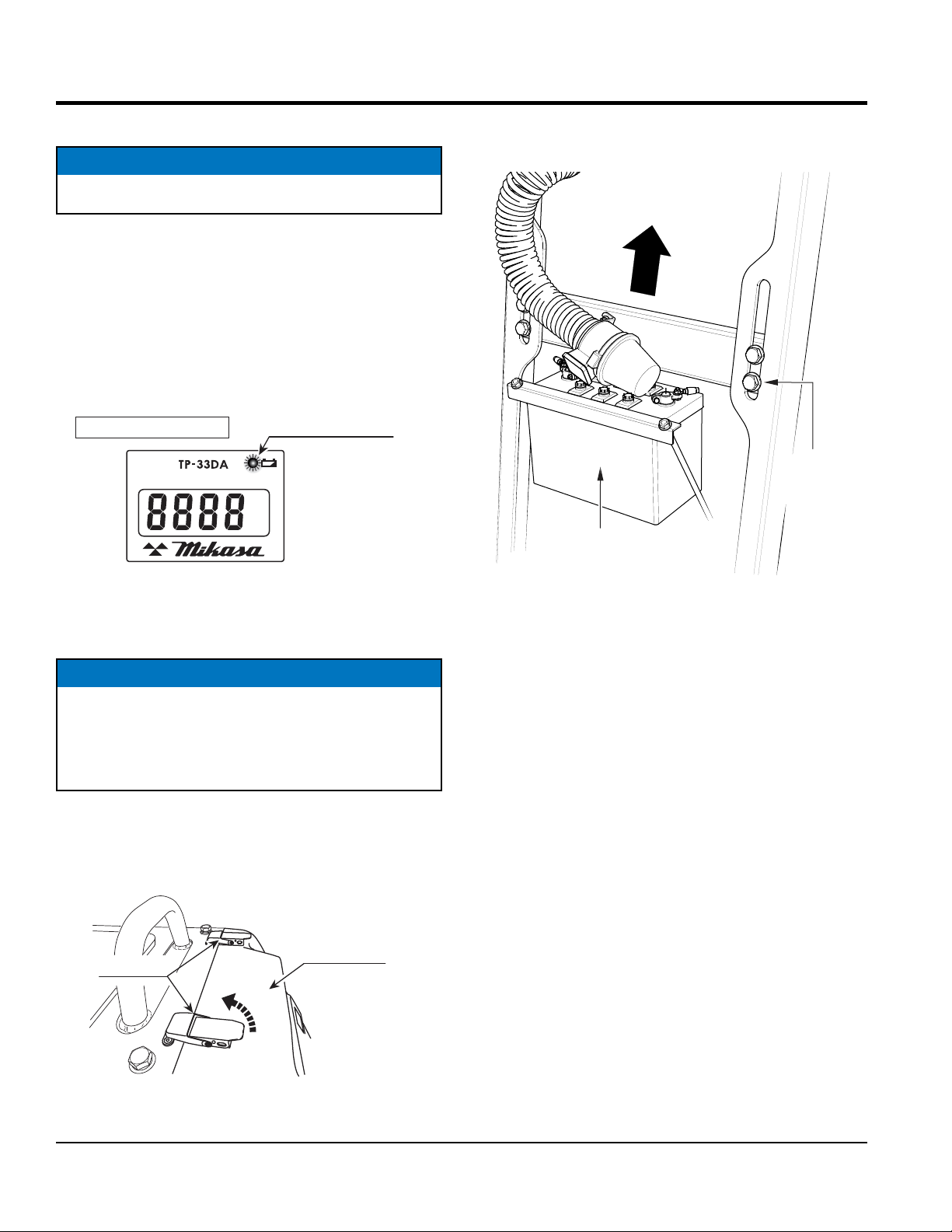
Checking Battery Capacity
1. Check the battery checker on the hour tachometer
(Figure 32).
HOUR TACHOMETER
DIESEL
ENGINE TACH
&HOUR
Battery checker
METER
2. Loosen the two bolts on each side of the bar connecting
the battery to the side rails (Figure 34).
SLIDE BAR UPWARD
TO ACCESS
BATTERY
LOOSEN
BOLT
(4 PLACES)
BATTERY
Figure 32. Battery Check
2. When the battery charge gets low, the battery checker
lights red.
NOTICE
If an old battery is used, even when the battery checker
is not lighted (indicating low charge), the cell starter
might not operate because of low charging level. If that
happens, change the battery with the new one.
Changing the Battery
1. Unlatch the two stoppers at the top portion of the rear
cover to open the rear cover (Figure 33).
Stopper
Rear cover
Figure 34. Raising the Battery
3. Slide the bar up the notches for easy access to the
battery and tighten the bolts.
4. Take off the nuts and remove the battery holder
(Figure 35).
5. After tilting the battery backward, disconnect the
battery terminal. Always disconnect the black terminal
on the negative side first.
6. Pull up the handle on the top of the battery to remove
the battery from the machine.(Figure 35). Make sure
that the battery terminals do not touch the frame.
Figure 33. Opening Rear Cover.
PAGE 30 — MVH508DZ PLATE COMPACTOR • OPERATION AND PARTS MANUAL — REV. #0 (04/04/14)
Page 31

MAINTENANCE
Nut
Battery holder
Battery
Handle
STORAGE
1. Wash off dirt and soil from every part with water. While
washing, be careful not to let the water splash on
the electric components such as the battery and the
engine muffler.
2. Cover the machine to prevent dust and dirt buildup.
3. Store the machine in a dry area away from direct
sunlight.
4. Do not leave the machine outdoors. Keep it indoors.
5. When not used for a long period of time, drain the fuel
from the fuel tank, and either disconnect the battery
terminals or remove the battery itself.
6. When the machine is used after a long storage period,
check the level of engine oil and battery capacity before
using.
Figure 35. Removing Battery
7. To install new battery, perform the procedure in reverse.
Make sure that the red terminal (positive side) is
connected first.
8. Loosen the two bolts on each side of the battery bracket
and slide the bracket down to lower the battery to its
original location.
9. Tighten the four bolts.
MVH508DZ PLATE COMPACTOR • OPERATION AND PARTS MANUAL — REV. #0 (04/04/14)— PAGE 31
Page 32

TROUBLESHOOTING (COMPACTOR)
Troubleshooting (Compactor)
Symptom Possible Problem Solution
Clutch slips? Adjust or replace clutch.
V-belt slips? Adjust or replace V-belt.
Excessive oil in vibrator? Fill to correct level.
Travel speed low and vibration
weak.
Travels forward or backward but
unable to switch direction.
Does not travel in forward or reverse
Check vibrator assembly for any
Trouble in vibrator internals?
Aeration in hydraulic oil for for travel
reversing system?
Engine speed incorrect? Set engine speed to correct RPM.
Hydraulic pump problems? Check hydraulic pump.
Direction Control Lever installation
wrong?
Broken or defective oil hose? Replace oil hose.
Aeration in hydraulic oil? Purge air in hydraulic oil. (Bleed plug)
Excessive oil in reversing system? Fill to correct level.
Hydraulic pump clogged with trash? Clean valve inside hydraulic pump.
Cylinder piston bearing failure?
V-belt disengaged or slips? Engage V-belt, adjust or replace.
Clutch slips? Adjust clutch, replace if necessary.
Vibrator locks? Check vibrator and correct problem.
worn or defective parts, replace any
defective parts.
Purge air in hydraulic oil. (Bleed plug)
Correct installation of lDirection
Control Lever.
Check piston bearing in cylinder for
leakage.
Cylinder piston bearing failure?
Piston inside hydraulic pump not
Direction Control Lever operating
resistance for reverse is high.
PAGE 32 — MVH508DZ PLATE COMPACTOR • OPERATION AND PARTS MANUAL — REV. #0 (04/04/14)
moving smoothly?
Vibrator cylinder piston does not move
smoothly
Check piston bearing in cylinder for
leakage at USH packing.
Adjust or replace.
Adjust or replace.
Page 33

Symptom Possible Problem Solution
Engine will not start or start is delayed,
although engine can be turned over.
At low temperatures engine will not start.
Engine fi res but stops soon as starter is
switched off.
Engine stops by itself during normal
operation.
Low engine power, output and speed.
TROUBLESHOOTING (ENGINE)
Troubleshooting (Engine)
No Fuel reaching injection pump? Add fuel. Check entire fuel system.
Defective fuel pump? Replace fuel pump.
Fuel fi lter clogged? Replace fuel fi lter and clean tank.
Faulty fuel supply line? Replace or repair fuel line.
Compression too low?
Fuel pump not working correctly? Repair or replace fuel pump.
Oil pressure too low? Check engine oil pressure.
Low starting temperature limit exceeded?
Defective battery? Charge or replace battery.
Air or water mixed in fuel system?
Engine oil too thick?
Defective battery? Replace battery.
Fuel fi lter blocked? Replace fuel fi lter.
Fuel supply blocked? Check the entire fuel system.
Defective fuel pump? Replace fuel pump.
Fuel tank empty? Add fuel.
Fuel fi lter blocked? Replace fuel fi lter.
Defective fuel pump? Replace fuel pump.
Mechanical oil pressure shutdown sensor
stops the engine due to low oil?
Fuel tank empty? Replace fuel fi lter.
Fuel fi lter clogged? Replace fuel fi lter.
Fuel tank venting is inadequate? Ensure that tank is adequately vented.
Leaks at pipe unions?
Speed control lever does not remain in
selected position?
Engine oil level too full? Correct engine oil level.
Injection pump wear?
Check piston, cylinder and valves. Adjust or
repair per engine repair manual.
Comply with cold starting instructions and
proper oil viscosity.
Check carefully for loosened fuel line
coupling, loose cap nut, etc.
Refi ll engine crankcase with correct type of
oil for winter environment.
Add oil. Replace low oil shutdown sensor if
necessary.
Check threaded pipe unions tape and tighten
unions a required.
See engine manual for corrective action.
Use No. 2-D diesel fuel only. Check the fuel
injection pump element and delivery valve
assembly and replace as necessary.
MVH508DZ PLATE COMPACTOR • OPERATION AND PARTS MANUAL — REV. #0 (04/04/14)— PAGE 33
Page 34

Symptom Possible Problem Solution
Low engine power output and low speed,
black exhaust smoke.
Engine overheats.
TROUBLESHOOTING (ENGINE)
Troubleshooting (Engine) - continued
Air fi lter blocked? Clean or replace air fi lter.
Incorrect valve clearances? Adjust valves per engine specifi cation.
Malfunction at injector? See engine manual.
Too much oil in engine crankcase?
Entire cooling air system contaminated/
blocked?
Fan belt broken or elongated? Change belt or adjust belt tension.
Coolant insuffi cient? Replenish coolant.
Radiator net or radiator fi n clogged with dust? Clean net or fi n carefully.
Fan, radiator, or radiator cap defective? Replace defective part.
Thermostat defective? Check thermostat and replace if necessary.
Head gasket defective or water leakage? Replace parts.
Drain off engine oil down to uppermark on
dipstick.
Clean cooling air system and cooling fi n
areas.
PAGE 34 — MVH508DZ PLATE COMPACTOR • OPERATION AND PARTS MANUAL — REV. #0 (04/04/14)
Page 35

EXPLANATION OF CODE IN REMARKS COLUMN
The following section explains the different symbols and
remarks used in the Parts section of this manual. Use the
help numbers found on the back page of the manual if there
are any questions.
SAMPLE PARTS LIST
NO.
1 12345 BOLT
2% WASHER, 1/4 IN.
2% 12347 WASHER, 3/8 IN.
3 12348 HOSE
4 12349 BEARING
NO. Column
PART NO. Column
QTY. Column
— Item quantity can be indicated by a
A/R (As Required) is generally used for hoses or other
A blank entry generally indicates that the item is not sold
separately. Other entries will be clarifi ed in the “Remarks”
Some of the most common notes found in the “Remarks”
Column are listed below. Other additional notes needed
— All items on the parts list with the
same unique symbol will be included when this item is
— Used to list an effective serial
— Indicates that the part
is used only with the specifi c model number or model
number variant listed. It can also be used to show a
part is NOT used on a specifi c model or model number
— Indicates that the part can
be purchased at any hardware shop or made out of
available items. Examples include battery cables, shims,
— Indicates that an item cannot
be purchased as a separate item and is either part of an
assembly/kit that can be purchased, or is not available
Numbers Used
number, a blank entry, or A/R.
NOTICE
The contents and part numbers listed in the parts
section are subject to change without notice. Multiquip
does not guarantee the availability of the parts listed.
PART NO. PART NAME QTY. REMARKS
.....................1 .....INCLUDES ITEMS W/%
..........NOT SOLD SEPARATELY
..1 .....MQ-45T ONLY
..................A/R ...MAKE LOCALLY
..............1 .....S/N 2345B AND ABOVE
Unique Symbols — All items with same unique symbol
(@, #, +, %, or >) in the number column belong to the
same assembly or kit, which is indicated by a note in the
“Remarks” column.
Duplicate Item Numbers — Duplicate numbers indicate
multiple part numbers, which are in effect for the same
general item, such as different size saw blade guards in
use or a part that has been updated on newer versions
of the same machine.
parts that are sold in bulk and cut to length.
Column.
REMARKS Column
to describe the item can also be shown.
Assembly/Kit
purchased.
Indicated by:
“INCLUDES ITEMS W/(unique symbol)”
Serial Number Break
number range where a particular part is used.
Indicated by:
“S/N XXXXX AND BELOW”
“S/N XXXX AND ABOVE”
“S/N XXXX TO S/N XXX”
NOTICE
When ordering a part that has more than one item
number listed, check the remarks column for help in
determining the proper part to order.
Numbers Used — Part numbers can be indicated by a
number, a blank entry, or TBD.
TBD (To Be Determined) is generally used to show a
part that has not been assigned a formal part number
at the time of publication.
A blank entry generally indicates that the item is not sold
separately or is not sold by Multiquip. Other entries will
be clarifi ed in the “Remarks” Column.
Specifi c Model Number Use
variant.
Indicated by:
“XXXXX ONLY”
“NOT USED ON XXXX”
“Make/Obtain Locally”
and certain washers and nuts.
“Not Sold Separately”
for sale through Multiquip.
MVH508DZ PLATE COMPACTOR • OPERATION AND PARTS MANUAL — REV. #0 (04/04/14)— PAGE 35
Page 36

SUGGESTED SPARE PARTS
MVH508DZ PLATE COMPACTOR WITH 1D81S-325 DIESEL ENGINE
1 to 5 units
Qty. P/N Description
4............070200483 ............V-BELT
4............939010010 ............SHOCK ABSORBER, STOPPER
3............50478800 ..............FUEL FILTER, IN-LINE
4............939010370 ............SHOCK ABSORBER
1............50384401 ..............IGNITION SWITCH
3............50404900 ..............KEY, IGNITION SWITCH
1............50385801 ..............CAP, FUEL TANK
1............50387300 ..............FUEL SIEVE
3............01493000 ..............ELEMENT, AIR FILTER
3............01480001 ..............ELEMENT, OIL FILTER W/ O-RING
NOTICE
Part numbers on this Suggested Spare Parts list may
supersede/replace the part numbers shown in the
following parts lists.
PAGE 36 — MVH508DZ PLATE COMPACTOR • OPERATION AND PARTS MANUAL — REV. #0 (04/04/14)
Page 37

NOTES
MVH508DZ PLATE COMPACTOR • OPERATION AND PARTS MANUAL — REV. #0 (04/04/14)— PAGE 37
Page 38

1
14
2
6
9
10
7
8
3
4
5
18
18
19
22
23
20
15
16
24
25
19
20
12
11
13
VIBRATING PLATE ASSY.
PAGE 38 — MVH508DZ PLATE COMPACTOR • OPERATION AND PARTS MANUAL — REV. #0 (04/04/14)
Page 39

VIBRATING PLATE ASSY.
NO. PART NO. PART NAME QTY. REMARKS
1 468121200 VIBRATING PLATE 1
2 465460670 OIL GAUGE 1
3 953402930 COPPER PACKING 1
4 953400270 PLUG 1
5 953405260 PACKING 1/4 1
6 939010370 SHOCK ABSORBER 4
7 020316130 NUT M16 4
8 030216400 WASHER, LOCK M16 4
9 001221635 BOLT 16X35 4
10 030216400 WASHER, LOCK M16 4
11 467219050 EXTENSION PLATE 2
12 012218050 BOLT 18X50 ......................................................8................REPLACES 001221850
13 58407 WASHER, LOCK M18 .......................................8................REPLACES 030218460
14 939010010 SHOCK ABSORBER, STOPPER 4
15 020310080 NUT M10 4
16 030210250 WASHER, LOCK M10 4
18 468352110 COVER, VIBRATING PLATE 2
19 014208020 BOLT 8X20 ........................................................8................REPLACES 001220820
20 030208200 WASHER, LOCK M8 8
22 467351790 COVER VIBRATOR 1
23 050103250 O-RING 1
24 014208020 BOLT 8X20........................................................18...............REPLACES 001220820
25 030208200 WASHER, LOCK M8 18
MVH508DZ PLATE COMPACTOR • OPERATION AND PARTS MANUAL — REV. #0 (04/04/14)— PAGE 39
Page 40

VIBRATOR ASSY.
1
1
17
51
52
46
48
49
47
27
30
28
29
31
32
30
35
34
36
41
44
43
40
B
D
C
A
33
11
15
13
14
1
20
21
22
23
20
24
12
12
16
16
C
D
6
6
1
2
3
6
6
7
4
8
42
5
5
7
A
B
PAGE 40 — MVH508DZ PLATE COMPACTOR • OPERATION AND PARTS MANUAL — REV. #0 (04/04/14)
Page 41

VIBRATOR ASSY.
NO. PART NO. PART NAME QTY. REMARKS
1 047920120 ROLLER BEARING 4
2 457212410 ROTARY SHAFT, DRIVE 1
3 951405370 KEY 15X10X39 1
4 456327150 GEAR, DRIVE 1
5 080200550 STOP RING 2
6 469352310 ECCENTRIC ROTATOR 4
7 009120301 SOCKET HEAD BOLT 16X40 2
8 060105030 OIL SEAL 1
11 456337670 ROTARY SHAFT, DRIVEN 1
12 009120302 SOCKET HEAD BOLT 16X30 2
13 456337380 PISTON ROD 1
14 456010010 KNOCK PIN 10X70 1
15 467351910 GEAR (DRIVEN) 1
16 040306911 BEARING 2
17 953010030 SEAL CAP 1
20 042506000 BEARING 6000ZZSG 2
21 0080000010 STOP RING .......................................................1................REPLACES 080200100
22 455435051 PISTON 1
23 455010070 PACKING 1
24 080100260 STOP RING 1
27 467352540 BEARING COVER 1
28 467219070 CYLINDER (R) 1
29 954010020 CONNECTOR PT, PF 1/4 1
30 050101050 O-RING 2
31 001720812 FLANGE BOLT 8X12 1
32 953404600 COPPER PACKING 1
33 959408880 CLIP 15 (M10) 1
34 0105091025 BOLT 10X25.......................................................8................REPLACES 001221025
35 030210250 WASHER, LOCK M10 8
36 031110160 WASHER, FLAT M10 8
40 469352320 PULLEY 1
41 456437920 WASHER, PULLEY 1
42 951404970 KEY 12X8X30 1
43 012212035 BOLT 12X35 .....................................................1................REPLACES 001221235
44 030212300 WASHER, LOCK M12 1
46 467351920 GUIDE, BELT COVER 1
47 014208020 BOLT 8X20 .......................................................2................REPLACES 001220820
48 030208200 WASHER, LOCK M8 2
49 0401450080 WASHER, FLAT M8 ..........................................2................REPLACES 031108160
51 469219030 BELT COVER, LOWER 1
52 001520860 SOCKET HEAD BOLT 8X100 5
MVH508DZ PLATE COMPACTOR • OPERATION AND PARTS MANUAL — REV. #0 (04/04/14)— PAGE 41
Page 42

73
46
11
12
B
C
38
39
37
A
41
42
43
52
53
54
40
55
56
51
A
41
42
43
95
See
“ELECTRIC DEVICE”
4
5
2
65
3
61
62
63
1
E
7
8
15
25
26
24
27
28
29
9
17
22
19
18
16
32
34
35
33
46
48
70
71
72
74
111
112
C
D
F
59
58
60
45
57
B
47
48
49
E
100
101
102
102
105
102
103
102
104
100
107
110
106
104
107
79
82
86
83
84
85
80
87
CRANK HANDLE
(ENGINE PARTS)
D
75
78
81
76
77
F
BASE AND ENGINE ASSY.
PAGE 42 — MVH508DZ PLATE COMPACTOR • OPERATION AND PARTS MANUAL — REV. #0 (04/04/14)
Page 43

BASE AND ENGINE ASSY.
NO. PART NO. PART NAME QTY. REMARKS
1 469121280 BASE 1
2 918401200 ENGINE ASSY. 1
3 009120205 STUD BOLT 12X25 4
4 030212300 WASHER, LOCK M12 4
5 0039312000 NUT M12 ...........................................................4................REPLACES 020312100
7 469352260 BELT COVER, IN 1
8 014210020 SOCKET HEAD BOLT 10X20 ............................3................REPLACES 001521020
9 030210250 WASHER, LOCK M10 3
11 469218980 DUST COVER 1
12 092006010 FLAT HEAD SCREW 6X10 6
15 469352390 CLUTCH ASSY. 1
16 951010130 KEY 7X7X49 1
17 952401390 WASHER 11X40X6 1
18 0105091025 BOLT 10X25.......................................................1................REPLACES 001221025
19 030210250 WASHER, LOCK M10 1
22 070200483 V-BELT, HDPF-5460 2
24 457339571 STUB SHAFT FAN 1
25 011208030 BOLT 8X30.........................................................4................REPLACES 001220830
26 030208200 WASHER, LOCK M8 4
27 457336380 FAN 1
28 014208020 BOLT 8X20.........................................................6................REPLACES 001220820
29 030208200 WASHER, LOCK M8 6
32 469218990 BELT COVER (OUT) 1
33 469352270 DUST SPONGE (OUT) 1
34 001521058 SOCKET HEAD BOLT 10X90 2
35 001521045 SOCKET HEAD BOLT 10X45 5
37 469352280 FRONT BUMPER 1
38 001521435 SOCKET HEAD BOLT 14X35 2
39 030214350 WASHER, LOCK M14 2
40 469121290 FRONT COVER 1
41 001221435 BOLT 14X35 T 4
42 030214350 WASHER, LOCK M14 4
43 031114260 WASHER, FLAT M14 4
45 469219330 CENTER COVER 1
46 001521440 SOCKET HEAD BOLT 14X40 4
47 031114260 WASHER, FLAT M14 2
48 030214350 WASHER, LOCK M14 4
49 020314110 NUT M14 2
51 468466890 RUBBER COVER, UPPER 1
52 467466760 STOPPER COVER 1
53 009120424 SOCKET HEAD BOLT 6X25 3
54 617465130 COLLAR 6.2X7.8X4.5 3
55 030206150 WASHER, LOCK M6 3
56 022710607 NYLON NUT M6 3
MVH508DZ PLATE COMPACTOR • OPERATION AND PARTS MANUAL — REV. #0 (04/04/14)— PAGE 43
Page 44

73
46
11
12
B
C
38
39
37
A
41
42
43
52
53
54
40
55
56
51
A
41
42
43
95
See
“ELECTRIC DEVICE”
4
5
2
65
3
61
62
63
1
E
7
8
15
25
26
24
27
28
29
9
17
22
19
18
16
32
34
35
33
46
48
70
71
72
74
111
112
C
D
F
59
58
60
45
57
B
47
48
49
E
100
101
102
102
105
102
103
102
104
100
107
110
106
104
107
79
82
86
83
84
85
80
87
CRANK HANDLE
(ENGINE PARTS)
D
75
78
81
76
77
F
BASE AND ENGINE ASSY. CONTINUED
PAGE 44 — MVH508DZ PLATE COMPACTOR • OPERATION AND PARTS MANUAL — REV. #0 (04/04/14)
Page 45

BASE AND ENGINE ASSY. CONTINUED
NO. PART NO. PART NAME QTY. REMARKS
57 469352890 CLEANER STAY 1
58 011208025 BOLT 8X25.........................................................4................REPLACES 001220825
59 030208200 WASHER, LOCK M8 4
60 467467580 PLATE, CLEANER STAY 2
61 469467000 GUIDE, DRAIN 1
62 011008015 BOLT 8X15 ........................................................1................REPLACES 001220815
63 030208200 WASHER, LOCK M8 1
65 469219010 SIDE COVER 1
70 001521251 SOCKET HEAD BOLT 12X55 4
71 030212300 WASHER, LOCK M12 4
72 031112230 WASHER, FLAT M12 4
73 2067550101 CLAMP COMPLETE 1
74 DH50642000 CLAMP 1
75 469219120 HOLDER, CRANK HANDLE 1
76 469467320 POLYURETHANE SEAT 222X50 1
77 469467310 POLYURETHANE SEAT 220X30 1
78 469467300 POLYURETHANE SEAT 80X30X5 1
79 469352530 HOLDER, CRANK HANDLE 1
80 469467330 POLYURETHANE SEAT 60X40 1
81 009120408 SUNK HEAD BOLT 8X20 2
82 959406961 GRIP BOLT 45X10X30 1
83 030210250 WASHER, LOCK M10 1
84 031110160 WASHER, FLAT M10 1
85 952403450 WASHER 11X35X4.5 1
86 952008940 SEAL WASHER 10X17X1.6 1
87 469467190 RUBBER PIPE 25X33X20 1
95 009120420 SOCKET HEAD BOLT 5X10 4
100 466218080 CLEANER, CYCLONE 2
101 469352300 CYCLONE STAY 1
102 466462850 GASKET, AIR INTAKE 4
103 469219020 JOINT CLEANER 1
104 009110057 SOCKET HEAD BOLT 5X18 6
105 011008015 BOLT 8X15 T......................................................4................REPLACES 001220815
106 030208200 WASHER, LOCK M8 4
107 506010060 CLAMP 2
110 466348590 DUCT HOSE 50X270 1
111 469467010 INTAKE PIPE 1
112 466462840 DUCT GROMMET 1
MVH508DZ PLATE COMPACTOR • OPERATION AND PARTS MANUAL — REV. #0 (04/04/14)— PAGE 45
Page 46

ELECTRIC DEVICE ASSY.
85
83
E
40
41
56
92
84
82
43
54
55
94
93
50
79
Engine
(front side)
42
23
37
24
100
BLACK
98
35
98
25
WHITE
WHITE
BLACK
GREEN
36
101
104
50
(WHITE)
53
15
(BLACK)
(RED)
30
103
GREEN
-
+
78
WHITE
RED
BLACK
D
11
91
96
26
90
18
See
“CONTROL”
32
28
51
31
33
30
29
15
12
Engine
(rear side)
The grounding
(-) BLACK
16
14
(+) RED
9
50
3
10
3
16
RED
86
102
45
49
Engine
(Starting motor)
2
4
5
1
D
E
97
80
46
47
48
PAGE 46 — MVH508DZ PLATE COMPACTOR • OPERATION AND PARTS MANUAL — REV. #0 (04/04/14)
Page 47

ELECTRIC DEVICE ASSY.
NO. PART NO. PART NAME QTY. REMARKS
1 467218920 BATTERY HOLDER 1
2 456447590 RUBBER PLATE (E) 1
3 456447600 RUBBER PLATE 2
4 012210020 BOLT 10X20.......................................................2................REPLACES 001221020
5 030210250 WASHER, LOCK M10 2
9 464313740 HOLDER, BATTERY 1
10 469467170 TIE-DOWN ROD, BATTERY 2
11 022710809 NYLON NUT M8 2
12 0401450080 WASHER, FLAT M8 ..........................................2................REPLACES 031108160
14 955301030 BATTERY CABLE (+) 1
15 955301040 BATTERY CABLE (-) 1
16 506010070 CLAMP 4
18 469121300 REAR COVER 1
23 014208020 BOLT 8X20 T .....................................................1................REPLACES 001220820
24 030208200 WASHER, LOCK M8 1
25 0401450080 WASHER, FLAT M8 ..........................................1................REPLACES 031108160
26 959408920 CLIP 8 (M8) 1
28 404433430 RUBBER 2
29 001521051 SOCKET HEAD BOLT 10X55 2
30 030210250 WASHER, LOCK M10 2
31 952403450 WASHER 2
32 467467250 RUBBER WASHER 2
33 417454420 COLLAR 2
35 469467470 CATCH CLIP .....................................................2................INCLUDES ITEM W/$
36 009120421 SOCKET HEAD BOLT 5X15 4
37$ 169467480 HOLDER, CATCH CLIP 2
40 469352340 BRACKET, STOPPER 1
41 939010360 STOPPER, RUBBER 2
42 020108060 NUT M8 .............................................................2................REPLACES 020308060
43 030208200 WASHER, LOCK M8 2
45 001200520 BOLT 5X20 3
46 030205130 WASHER, LOCK M5 3
47 022710506 NYLON NUT M5 3
48 467466930 RUBBER PLATE, BATTERY 1
49 467466920 STOPPER, RUB-PLATE 1
50 454010020 CLAMP 1
MVH508DZ PLATE COMPACTOR • OPERATION AND PARTS MANUAL — REV. #0 (04/04/14)— PAGE 47
Page 48

ELECTRIC DEVICE ASSY. CONTINUED
85
83
E
40
41
56
92
84
82
43
54
55
94
93
50
79
Engine
(front side)
42
23
37
24
100
BLACK
98
35
98
25
WHITE
WHITE
BLACK
GREEN
36
101
104
50
(WHITE)
53
15
(BLACK)
(RED)
30
103
GREEN
-
+
78
WHITE
RED
BLACK
D
11
91
96
26
90
18
See
“CONTROL”
32
28
51
31
33
30
29
15
12
Engine
(rear side)
The grounding
(-) BLACK
16
14
(+) RED
9
50
3
10
3
16
RED
86
102
45
49
Engine
(Starting motor)
2
4
5
1
D
E
97
80
46
47
48
PAGE 48 — MVH508DZ PLATE COMPACTOR • OPERATION AND PARTS MANUAL — REV. #0 (04/04/14)
Page 49

ELECTRIC DEVICE ASSY. CONTINUED
NO. PART NO. PART NAME QTY. REMARKS
51 467352050 PANEL, REAR COVER 1
53 009110062 SOCKET HEAD SCREW 6X20 4
54 952404470 WASHER, FLAT M6 ..........................................4................REPLACES 031106100
55 030206150 WASHER, LOCK M6 4
56 022710607 NYLON NUT M6 4
78 465459680 RELAY CABLE/BUZZER 1
79 959026021 CORRUGATE TUBE 1
80 959020014 SPIRAL TUBE 1
82 469352400 PANEL, WITH BUZZER 1
83 001220635 BOLT 6X35 1
84 030206150 WASHER, LOCK M6 1
85 001520530 SOCKET HEAD BOLT 5X30 2
86 506010070 CLAMP 1
90 009110072 PAN HEAD SCREW 5X35 2
91 952407930 COLLAR 6X10X13.5 2
92 022710506 NYLON NUT M5 2
93 030205130 WASHER, LOCK M5 2
94 58151 WASHER, FLAT M5 ..........................................2................REPLACES 031105080
96 955301020 TACH. AND HOUR METER 1
97 469467040 RESISTOR, TACH. 1
98 955407970 WIRING FIXED BASE 2
101 50384401 IGNITION SWITCH W/ KEY ..............................1................INCLUDES ITEM W/ @
102 469352350 WIRE HARNESS 1
103 50465100 BUZZER 1
104@ 50404900 KEY, IGNITION SWITCH 1
MVH508DZ PLATE COMPACTOR • OPERATION AND PARTS MANUAL — REV. #0 (04/04/14)— PAGE 49
Page 50

CONTROL ASSY.
1
3
4
5
7
12
8
9
10
11
13
2
3
4
5
7
8
11
14
15
10
9
29
27
34
35
25
26
28
16
36
38
39
37
40
59
44
46
47
48
45
43
61
60
62
18
21
20
19
77
78
63
64
68
75
67
69
71
51
85
53
80
84
81
76
70
82
83
49
55
56
50
57
58
52
57
58
22
23
13
72
74
73
PAGE 50 — MVH508DZ PLATE COMPACTOR • OPERATION AND PARTS MANUAL — REV. #0 (04/04/14)
Page 51

CONTROL ASSY.
NO. PART NO. PART NAME QTY. REMARKS
1 467351950 HANDLE BRACKET (R) 1
2 467351960 HANDLE BRACKET (L) 1
3 012212035 BOLT 12X35.......................................................4................REPLACES 001221235
4 030212300 WASHER, LOCK M12 4
5 031112230 WASHER, FLAT M12 4
7 456336400 RUBBER COUPLING 2
8 456449940 SHOCK ABSORBER 2
9 025306016 SPRING PIN 6X16 ............................................2................REPLACES 025406016
10 456449930 RUBBER PLATE 2
11 032124400 CONICAL WASHER LOCK M24 2
12 001221681 BOLT 16X250 1
13 0401450160 WASHER, FLAT M16 ........................................2................REPLACES 031116260
14 020316130 NUT M16 1
15 020416100 NUT M16 1
16 467121170 HANDLE BAR 1
18 455434950 SPINDLE 1
19 455010030 KNOB 1
20 020412070 NUT M12 1
21 022411635 WING NUT M16 1
22 939010060 SHOCK ABSORBER 1
23 020310080 NUT M10 ............................................................1................REPLACES 020410060
25 959408930 CLIP 1
26 011206020 BOLT 6X20.........................................................1................REPLACES 001220620
27 030206150 WASHER, LOCK M6 1
28 952404470 WASHER, FLAT M6 ..........................................1................REPLACES 031106100
29 020106050 NUT M6 .............................................................1................REPLACES 020306050
34 501402870 HANDLE STOPPER 1
35 501402880 SPRING/HANDLE 1
36 959403460 BALL GRIP 1
37 020310080 NUT M10 ............................................................1................REPLACES 020410060
38 456449980 RUBBER PACKING 1
39 953405260 PACKING 1/4 1
40 031110160 WASHER, FLAT M10 1
43 467351970 HANDLE COVER 1
43 467351970 HANDLE COVER 1
MVH508DZ PLATE COMPACTOR • OPERATION AND PARTS MANUAL — REV. #0 (04/04/14)— PAGE 51
Page 52

CONTROL ASSY. CONTINUED
83
84
80
82
70
76
81
72
74
73
59
57
58
55
16
52
49
50
56
61
58
60
57
62
46
47
48
43
45
44
53
78
77
36
63
37
12
13
3
4
5
1
11
64
7
40
38
39
9
10
8
35
51
85
26
29
27
75
19
68
20
18
21
28
25
10
9
67
71
69
3
4
7
5
PAGE 52 — MVH508DZ PLATE COMPACTOR • OPERATION AND PARTS MANUAL — REV. #0 (04/04/14)
Page 53

CONTROL ASSY. CONTINUED
NO. PART NO. PART NAME QTY. REMARKS
44 467467340 PACKING (L), HANDLE 1
45 467467350 PACKING (R), HANDLE 1
46 0105050616 BOLT 6X15 T .....................................................6................REPLACES 001220615
47 030206150 WASHER, LOCK M6 6
48 952404470 WASHER, FLAT M6 ..........................................6................REPLACES 031106100
49 464457930 RUBBER PIECE 1
50 469219180 HYDRAULIC PUMP 1
51 954003100 OIL HOSE 1
52 458451630 BREATHER CAP 1
53 959021813 SPIRAL TUBE 1
55 464216630 TRAVEL LEVER 1
56 464457400 HANDLE BOSS 1
57 012010030 BOLT 10X30.......................................................2................REPLACES 001221030
58 030210250 WASHER, LOCK M10 2
59 467218900 GRIP 1
60 030210250 WASHER, LOCK M10 2
61 031110160 WASHER, FLAT M10 2
62 020310080 NUT M10 2
63 0105091025 BOLT 10X25.......................................................2................REPLACES 001221025
64 030210250 WASHER, LOCK M10 2
67 469466970 THROTTLE LEVER 1
68 959403840 BAR GRIP, I.D. 1
69 464457420 COVER , THROTTLE LEVER 1
70 464457350 ARM, THROTTLE 1
71 014208020 SOCKET HEAD BOLT 8X20 ..............................1................REPLACES 001520820
72 952408950 WASHER 1
73 952409020 WASHER 1
74 033910080 CONICAL WASHER, LOCK 3
75 464457440 STEEL BALL 1
76 464010010 DRY BUSHING 1
77 011606025 BOLT 6X25.........................................................2................REPLACES 001220625
78 020106050 NUT M6 .............................................................2................REPLACES 020306050
80 464010020 ROD END M5 1
81 001520520 SOCKET HEAD BOLT 5X20 1
82 58151 WASHER, FLAT M5 ..........................................1................REPLACES 031105080
83 020305040 NUT M5 1
84 956100071 THROTTLE WIRE 1
85 454010020 CLAMP 1
MVH508DZ PLATE COMPACTOR • OPERATION AND PARTS MANUAL — REV. #0 (04/04/14)— PAGE 53
Page 54

2
8
21
20
3
6
11
15
17
16
23
7
19
22
5
14
1
4
12
13
19
NAMEPLATE AND DECALS ASSY.
PAGE 54 — MVH508DZ PLATE COMPACTOR • OPERATION AND PARTS MANUAL — REV. #0 (04/04/14)
Page 55

NAMEPLATE AND DECALS ASSY.
NO. PART NO. PART NAME QTY. REMARKS
1 920204580 DECAL, FULL THROTTLE 1
2 920203330 DECAL, EAR PROTECTION 1
3 920211060 DECAL, CAUTION LEVER 1
4 920211090 DECAL, SHELL TELLUS OIL 32 1
5 920201950 DECAL, OIL SAE 10W-30 1
6 920106760 DECAL, STOP-RUN-START 1
7 920214200 DECAL, CAUTION CYCLONE 1
8 920214100 DECAL, E/G FIRE WARNING 1
12 920217130 DECAL, MIKASA MARK(W) 200L 2
13 920217110 DECAL, MIKASA MARK 35X70 2
14 920201580 DECAL, MQ MARK 71X55 1
15 920218390 DECAL, CAUTION 1
16 920217700 DECAL, V-BELT HDPF-5480 1
17 920218150 DECAL, E/G RPM 2400 1
19 920217810 DECAL, MODEL (R) 2
20 920217820 DECAL, MODEL (L) 1
21 920217610 PLATE, SERIAL NO. 1
22 920214740 DECAL, LIFTING POSITION 1
23 920214730 DECAL, DO NOT LIFT 1
MVH508DZ PLATE COMPACTOR • OPERATION AND PARTS MANUAL — REV. #0 (04/04/14)— PAGE 55
Page 56

HATZ 1D81S-325 ENGINE SPARE PARTS KIT ASSY.
1
2
6
3
7
8
9
PAGE 56 — MVH508DZ PLATE COMPACTOR • OPERATION AND PARTS MANUAL — REV. #0 (04/04/14)
Page 57

HATZ 1D81S-325 ENGINE SPARE PARTS KITS ASSY.
NO. PART NO. PART NAME QTY. REMARKS
1 1517802 GASKET SET, CYLINDER HEAD 1
2 1249322 GASKET SET, CRANK CASE 1
3 1249410 MAINTENANCE KIT, 1000H 1
6 1942000 REPAIR SET, CAPSULE 1
7 2265300 FILTER KIT, LIGHT 1
8 2268500 FILTER KIT, MEDIUM 1
9 2269600 FILTER KIT, HEAVY 1
MVH508DZ PLATE COMPACTOR • OPERATION AND PARTS MANUAL — REV. #0 (04/04/14)— PAGE 57
Page 58

....
HATZ 1D81S-325 ENGINE ACCESSORIES ASSY.
M
1
3
7
2
A B C D E
LOCTITE
ACTIVATOR N
F F1 G H
TECH. ADHES.
8058
LOCTITE 574
TECH.
CLEANER
LOCTITE 601
LOCTITE 407
LOCTITE 221
TEROSON
TEROSTAT 63
LOCTITE 648
J
HIGH TEMP
PASTE
K L M
HOCHTEMP.
FETT 400G
SILICON
SEALER
GRINDING
PASTE 80ML
PAGE 58 — MVH508DZ PLATE COMPACTOR • OPERATION AND PARTS MANUAL — REV. #0 (04/04/14)
Page 59

HATZ 1D81S-325 ENGINE ACCESSORIES ASSY.
NO. PART NO. PART NAME QTY. REMARKS
A 50223001 LOCTITE ACTIVATOR N 1
B 50223101 LOCTITE 574 1
C 50223200 LOCTITE 601 1
D 50223300 LOCTITE 221 1
E 50223400 LOCTITE 648 1
F 50223800 TECHNICAL ADHESIVE 8058 1
F1 50223900 TECHNICAL CLEANER 1
G 50256501 LOCTITE IS 407 1
H 70018944 TEROSON TEROSTAT 63 1
J 50283004 HIGH TEMPERATURE PASTE 1
K 50342601 HIGH TEMPERATURE FETT 1
L 50256600 SILICON SEALER 1
M 50485100 GRINDING PASTE 1
1 01247512 ACCESSORIES KIT 1
2 01247600 TOOLS 1
3 04048305 STICKER DECAL 1
7 05025201 STICKER DECAL "START" 1
MVH508DZ PLATE COMPACTOR • OPERATION AND PARTS MANUAL — REV. #0 (04/04/14)— PAGE 59
Page 60

HATZ 1D81S-325 ENGINE CRANKCASE 1 ASSY.
SEALING AND BONDING
ADHESIVES
A D
H
E
29
28
3
13
3
12
15
15
24
14
26
1
3
4
5
9
27
18
19
6
11
16
10
23
3
9
7
32
17
NOT SOLD SEPARATELY
PAGE 60 — MVH508DZ PLATE COMPACTOR • OPERATION AND PARTS MANUAL — REV. #0 (04/04/14)
Page 61

HATZ 1D81S-325 ENGINE CRANKCASE 1 ASSY.
NO. PART NO. PART NAME QTY. REMARKS
A 50223001 LOCTITE ACTIVATOR N 1
D 50223300 LOCTITE 221 1
E 50223400 LOCTITE 648 1
H 70018944 TEROSON TEROSTAT 63 1
1 01249070 CRANKCASE ASSY. ..........................................1................INCLUDES ITEMS /$
2$ CRANKCASE .....................................................1................NOT SOLD SEPARATELY
3$ 50249102 CYL. PIN 4
4$ 03793900 NOZZLE 1
5$ 03793801 BEARING BUSH 1
6$ 03794000 PLUG AR
7$ 03793700 BEARING 1
7 04033700 MAIN BEARING, O.S. 0.5MM ............................1................FOR -0.5MM SHAFT
9$ 04000800 PLUG AR
10$ 50144300 STUD 2
11$ 03794510 STUD 1
12$ 03794800 INTERMEDIATE PIECE 1
13$ 50601200 STUD 2
14$ 50325500 COVER 1
15$ 50602901 STUD 8
16$ 50328200 STUD 2
17 02228000 THRUST PLATE.................................................1................INCLUDES ITEMS W/@
18 04069500 SHIM, 1.05 MM AR
18 04069600 SHIM, 1.2 MM AR
19 04062010 HEX. HD. SCREW 4
23 50328200 STUD 1
24$ PIPE ...................................................................1................NOT SOLD SEPARATELY
26$ O-RING ............................................................ AR .............. NOT SOLD SEPARATELY
27$ 04105000 PLUG 1
28 50459800 SEALING CYL. SCREW 2
29 04084500 SEALING RING 2
30$ STUD ............................................................... AR .............. NOT SOLD SEPARATELY
31@ GASKET ............................................................1................NOT SOLD SEPARATELY
32@ PLATE ................................................................1................NOT SOLD SEPARATELY
MVH508DZ PLATE COMPACTOR • OPERATION AND PARTS MANUAL — REV. #0 (04/04/14)— PAGE 61
Page 62

60
61
28
32
56
32
59
35
34
28
27
31
29
26
23
22
24
8
7
6
16
16
15
17 18
15
16
D
D
1
2
3
4
4
3
2
1
D
5
5
11
12
13
D
D
D
H
H
10
H
K
6
20
H
62
63
21
21
15
18
17
14
27
H
SEALING AND BONDING
ADHESIVES
D
K
NOT SOLD SEPARATELY
39
HATZ 1D81S-325 ENGINE CRANKCASE 2 ASSY.
PAGE 62 — MVH508DZ PLATE COMPACTOR • OPERATION AND PARTS MANUAL — REV. #0 (04/04/14)
Page 63

HATZ 1D81S-325 ENGINE CRANKCASE 2 ASSY.
NO. PART NO. PART NAME QTY. REMARKS
D 50223300 LOCTITE 221 1
H 70018944 TEROSON TEROSTAT 63 1
K 50342601 HIGH TEMPERATURE FETT 1
1 03794100 WASHER 2
2 03794300 CAM FOLLOWER 2
3 03794201 CAM FOLLOW SP. 2
4 50545501 ALLEN, SCREW 2
5 03795800 O-RING 2
6 50329000 O-RING 3
7 03795100 O-RING 1
8 01248810 PLATE 1
10 50417600 ALLEN SCREW W / WASHER 22
11 03794900 HOUSING 1
12 03795000 SUCTION, SIEVE 1
13 50327100 ALLEN SCREW 2
14 01241700 OIL SUMP 1
15 50170900 WASHER, LOCK 12
16 50329100 ALLEN SCREW 12
17 50001600 JOINT A 2
18 50373100 DRAIN PLG. MAGNT. 2
20 03794701 COVER 1
21 50328300 HEXAGON NUT 3
22 01321200 CLOS., SCREW +SIEVE 1
23 50286400 JOINT A 1
24 01321100 OIL RELIEF VALVE W/O-RING ..........................1................INCLUDES ITEMS W/$
25$ OIL RELIEF VALVE ............................................1................NOT SOLD SEPARATELY
26$ 50460400 O-RING 1
27 50062400 JOINT A 2
28 50062300 CLOS. SCREW 2
29 01241500 OIL GAUGE W/O-RING ....................................1................INCLUDES ITEMS W/#
30# OIL GAUGE .......................................................1................NOT SOLD SEPARATELY
31# 50359700 O-RING 2
32@% 50329200 RING 2
33+ HOUSING, LUBE, OIL FILTER ..........................1................NOT SOLD SEPARATELY
34 50081200 WASHER, LOCK 4
35 50170600 ALLEN SCREW 4
36@ ELEMENT, OIL FILTER ......................................1................NOT SOLD SEPARATELY
37% COVER, OIL FILTER..........................................1................NOT SOLD SEPARATELY
39 01480001 ELEMENT, OIL FILTER W/RING .......................1................INCLUDES ITEMS W/@
56 04084001 LIFTING SPRING 1
59+ 05068900 GASKET 1
60 01318300 HOUSING, LUBE, OIL FILTER, W/GASKET ....1................INCLUDES ITEMS W/+
61 01248901 COVER, OIL FILTER W/RING ...........................1................INCLUDES ITEMS W/%
62 50144500 WASHER, FLAT 2
63 50170900 WASHER, LOCK 2
MVH508DZ PLATE COMPACTOR • OPERATION AND PARTS MANUAL — REV. #0 (04/04/14)— PAGE 63
Page 64

HATZ 1D81S-325 ENGINE CRANKSHAFT BEARING FLANGE ASSY.
14
25
12
16
15
B
11
9
8
23
E
3
1
E
6
7
4
5
24
SEALING AND BONDING
ADHESIVES
E
B
NOT SOLD SEPARATELY
PAGE 64 — MVH508DZ PLATE COMPACTOR • OPERATION AND PARTS MANUAL — REV. #0 (04/04/14)
Page 65

HATZ 1D81S-325 ENGINE CRANKSHAFT BEARING FLANGE ASSY.
NO. PART NO. PART NAME QTY. REMARKS
B 50223101 LOCTITE 574 1
E 50223400 LOCTITE 648 1
1 01269820 CRANKSHAFT ASSY. ........................................1................INCLUDES ITEMS W/$
2$ CRANKSHAFT ...................................................1................NOT SOLD SEPARATELY
3$ PLUG .................................................................1................NOT SOLD SEPARATELY
4 03796000 COUNTER WEIGHT 1
5 50055001 ALLEN SCREW 2
6$ 50362600 FITTING KEY 1
7 03796120 GEARWHEEL, CRANKSHAFT 1
8 04000600 BUFFER RING 1
9 50224900 O-RING 1
11 04064211 BEARING FLANGE ..........................................1................REPLACES 04064210
12 04006800 MAIN BEARING 1
12 04036100 MAIN BEARING, O.S. 0.5MM ............................1................FOR -0.5MM SHAFT
14 50362701 OIL SEAL 1
15 50413600 WASHER 8
16 50364300 HEXAGON NUT 8
23 50414400 WEAR SLEEVE AR
24 01512010 REPAIR SET, CRANKSHAFT 1
MVH508DZ PLATE COMPACTOR • OPERATION AND PARTS MANUAL — REV. #0 (04/04/14)— PAGE 65
Page 66

HATZ 1D81S-325 ENGINE CAMSHAFT ASSY.
4
PAGE 66 — MVH508DZ PLATE COMPACTOR • OPERATION AND PARTS MANUAL — REV. #0 (04/04/14)
Page 67

HATZ 1D81S-325 ENGINE CAMSHAFT ASSY.
NO. PART NO. PART NAME QTY. REMARKS
4 04099920 CAMSHAFT ASSY. 1
MVH508DZ PLATE COMPACTOR • OPERATION AND PARTS MANUAL — REV. #0 (04/04/14)— PAGE 67
Page 68

ピストン
8
6
4
5
3
5
12
11
14
13
13
9
10
1
HATZ 1D81S-325 ENGINE PISTON ASSY.
PAGE 68 — MVH508DZ PLATE COMPACTOR • OPERATION AND PARTS MANUAL — REV. #0 (04/04/14)
Page 69

HATZ 1D81S-325 ENGINE PISTON ASSY.
NO. PART NO. PART NAME QTY. REMARKS
1# 01313542 PISTON SET 100 STD. ......................................1................INCLUDES ITEMS W/$
1 01314641 PISTON 100+0.5MM OVERSIZE .......................1................INCLUDES ITEMS W/%
3$%# PISTON ..............................................................1................NOT SOLD SEPARATELY
4$%# 50461900 GUDGEON 1
5$%# 50594900 CIR CLIP 2
6$# 01247310 PISTON RING SET 100/STD 1
6% 01264510 PISTON RING SET100+0.5MM OVERSIZE 1
8# CYLINDER .........................................................1................NOT SOLD SEPARATELY
9 01508330 CYLINDER ASSY. .............................................1................INCLUDES ITEMS W/#
10 01244001 CONNECTING ROD ASSY. ..............................1................INCLUDES ITEMS W/@
11@ CONNECTING ROD ..........................................1................NOT SOLD SEPARATELY
12@ 04032200 BUSH FOR CONROD 1
13@ 04001810 CONROD SCREW 2
14 02251900 BEARING, BIG END STANDARD 1
14 02252100 BEARING, BIG END, O.S. 0.5MM .....................1................FOR -0.5MM BRG END
MVH508DZ PLATE COMPACTOR • OPERATION AND PARTS MANUAL — REV. #0 (04/04/14)— PAGE 69
Page 70

55
55
57
53
27
44
61
50
3
9
83
10
11
12
20
21
17
18
15
91
49
48
19
※13
85
21
20
11
9
83
3
45
61
1
24
25
26
23
35,36,37,38,39,40,41,42,43
7
6
67
60
31
28
29
5
67
66
4
90
46
47
48
49
※22
10
8
8
51
52
K
K
1D50
SEALING AND BONDING
ADHESIVES
K
NOT SOLD SEPARATELY
HATZ 1D81S-325 ENGINE CYLINDER HEAD ASSY.
PAGE 70 — MVH508DZ PLATE COMPACTOR • OPERATION AND PARTS MANUAL — REV. #0 (04/04/14)
Page 71

HATZ 1D81S-325 ENGINE CYLINDER HEAD ASSY.
NO. PART NO. PART NAME QTY. REMARKS
K 50342601 HIGH TEMPERATURE FETT 1
1 01499620 CYLINDER HEAD ASSY. ...................................1................INCLUDES ITEMS W/$
2$ CYLINDER HEAD ..............................................1................NOT SOLD SEPARATELY
3$ 04008712 VALVE GUIDE 2
4$ 50038400 STUD 1
5 01468920 SHAFT ROCKER W/O-RING .............................1................INCLUDES ITEMS W/%
6 04091001 INTAKE VALVE 1
7 04091100 EXHAUST VALVE 1
8 04005201 WASHER 2
9 04005300 VALVE SPRING 2
10 04005401 CUP 2
11 02252200 COLLET 2
12 04003710 ROCKER INLET 1
13^ ROCKER, EXHAUST .........................................1................NOT SOLD SEPARATELY
14* GEAR HOLDER .................................................1................NOT SOLD SEPARATELY
15* 03778401 SPRING SHEET 1
16% SHAFT ROCKER ...............................................1................NOT SOLD SEPARATELY
17 50117200 CIRCLIP 1
18* 03365710 RATCHET F DECOMPR 1
19* 03366001 SPRING 1
20 03783000 ADJUSTING SCREW 2
21 03173100 HEXAGON NUT 2
22^ PIN, ROCKER EXHAUST ..................................1................NOT SOLD SEPARATELY
23 50123800 BALL 1
24 04004700 BUSH 1
25 04004800 PRESSURE SPRING 1
26 01245200 ADJUSTING SCREW 1
27 50001100 JOINT A 1
28 04048900 RUBBER, RING 1
29% 40022401 O-RING 1
30 50034700 PIN 1
31 04009810 HANDLE 1
35 04068800 GASKET F. CYLINDER HEAD 0.5 MM 1
35 04240900 GASKET CYLINDER HEAD 0.55 MM 1
36 04036800 GASKET F. CYLINDER HEAD 0.6 MM 1
36 04241000 GASKET F. CYLINDER HEAD 0.65 MM 1
37 04036500 GASKET F. CYLINDER HEAD 0.7 MM 1
37 04241100 GASKET F. CYLINDER HEAD 0.75 MM 1
38 04036600 GASKET F. CYLINDER HEAD 0.8 MM 1
38 04241200 GASKET F. CYLINDER HEAD 0.85 MM 1
39 04002700 GASKET F. CYLINDER HEAD 0.9 MM 1
39 04241300 GASKET F. CYLINDER HEAD 0.95 MM 1
40 04002800 GASKET F. CYLINDER HEAD 1.0 MM 1
40 04241400 GASKET F. CYLINDER HEAD 1.05 MM 1
MVH508DZ PLATE COMPACTOR • OPERATION AND PARTS MANUAL — REV. #0 (04/04/14)— PAGE 71
Page 72

HATZ 1D81S-325 ENGINE CYLINDER HEAD ASSY. (CONTINUED)
55
55
57
53
27
44
61
50
3
9
83
10
11
12
20
21
17
18
15
91
49
48
19
※13
85
21
20
11
9
83
3
45
61
1
24
25
26
23
35,36,37,38,39,40,41,42,43
7
6
67
60
31
28
29
5
67
66
4
90
46
47
48
49
※22
10
8
8
51
52
K
K
1D50
SEALING AND BONDING
ADHESIVES
K
NOT SOLD SEPARATELY
PAGE 72 — MVH508DZ PLATE COMPACTOR • OPERATION AND PARTS MANUAL — REV. #0 (04/04/14)
Page 73

HATZ 1D81S-325 ENGINE CYLINDER HEAD ASSY. (CONTINUED)
NO. PART NO. PART NAME QTY. REMARKS
41 04002900 GASKET F. CYLINDER HEAD 1.1 MM 1
41 04241500 GASKET F. CYLINDER HEAD 1.15 MM 1
42 04003000 GASKET F. CYLINDER HEAD 1.2 MM 1
42 04241600 GASKET F. CYLINDER HEAD 1.25 MM 1
43 04003100 GASKET F. CYLINDER HEAD 1.3 MM 1
44 04003200 CYLINDER HEAD SCREW 2
45 04003300 CYLINDER HEAD SCREW 2
46 04006111 GASKET, ROCKER COVER 1
47 01245414 COVER CYLINDER HEAD 1
48 50081200 WASHER, LOCK 4
49 50170800 ALLEN SCREW 4
50 04008100 LIFTING BRACKET 1
51 50366300 ALLEN SCREW 2
52 50208500 WASHER, LOCK 2
53 01493200 PLUG, FILTER, ASSY. .......................................1................INCLUDES ITEMS W/@
54@ CAP, FILTER PLUG ...........................................1................NOT SOLD SEPARATELY
55@+ 50326200 O-RING 2
56@+ PLUG, FILTER ...................................................1................NOT SOLD SEPARATELY
57 01308301 CLOSING PLUG "S" W/O-RING & CAP ............1................INCLUDES ITEMS W/ +
60 01269700 OIL PRESSURE PIPE W/SPRING & ORINGS..1................INCLUDES ITEMS W/ #
61 03457500 DISC F. STUD 4
66# 04004200 PRESSURE SPRING 1
67# 50330100 O-RING 2
72# PIPE OIL PRESSURE .......................................1................NOT SOLD SEPARATELY
83 50634900 VALVE STEM SEAL CAP 2
85 01285010 ROCKER EXHAUST .........................................1................INCLUDES ITEMS W/ ^
90 04104300 PIN 1
91 01557600 GEAR, HOLDER, F. DECOMPR .......................1................INCLUDES ITEMS W/*
MVH508DZ PLATE COMPACTOR • OPERATION AND PARTS MANUAL — REV. #0 (04/04/14)— PAGE 73
Page 74

HATZ 1D81S-325 ENGINE PUSHROD, FLYWHEEL ASSY.
1
16
15
14
13
2
3
8
10
10
4
5
6
7
10
10
10
PAGE 74 — MVH508DZ PLATE COMPACTOR • OPERATION AND PARTS MANUAL — REV. #0 (04/04/14)
Page 75

HATZ 1D81S-325 ENGINE PUSHROD, FLYWHEEL ASSY.
NO. PART NO. PART NAME QTY. REMARKS
1 01244310 PUSHROD 2
2 50330200 O-RING 2
3 04002500 PROTECTION TUBE 2
4 50347000 CIRCLIP 2
5 04002600 PRESSURE SPRING 2
6 04002000 PRESSURE RING 2
7 50330300 O-RING 2
8 04007500 RING, FLYWHEEL 2
10 50397100 ALLEN SCREW 1
13 03123700 BUSHING 7
14 04007133 FLYWHEEL 1
15 04007410 PLATE 1
16 50363100 ALLEN SCREW 6
MVH508DZ PLATE COMPACTOR • OPERATION AND PARTS MANUAL — REV. #0 (04/04/14)— PAGE 75
Page 76

HATZ 1D81S-325 ENGINE OIL PUMP, GOVERNOR ASSY.
M10 OIL PUMP,GOVERNOR
/
オイルポンプ、ガバナ
SEALING AND BONDING
ADHESIVES
17
16
10
15
14
12
1
2
20
H
13
12
21
11
21
H
18
16
19
3
23
NOT SOLD SEPARATELY.
4
6
7
22
8
PAGE 76 — MVH508DZ PLATE COMPACTOR • OPERATION AND PARTS MANUAL — REV. #0 (04/04/14)
Page 77

HATZ 1D81S-325 ENGINE OIL PUMP, GOVERNOR ASSY.
NO. PART NO. PART NAME QTY. REMARKS
H 70018944 TEROSON TEROSTAT 63 1
1 50328000 COUNTERSUNK SCREW 5
2$ 03797412 COVER, OIL PUMP 1
3$ 01242401 SPRING CAPSULE+BUSH 1
4$ 03797310 GEAR WHEEL 1
6 04063400 GOVERNOR SPRING 1
7 03798600 CUP 1
8 50334700 CIRCLIP 1
10$ 03797512 HOUSING FOR OIL PUMP 1
11$ 04277100 PLATE, CENTRIFUGAL WEIGHT 1
12$ 04277300 PIN 1
13$ 04277202 FLYWEIGHT 1
14 03797900 WASHER 1
15 03797801 PIN 1
16 50081200 WASHER, LOCK 5
17 50170800 ALLEN SCREW 3
18 50051000 ALLEN SCREW 2
19 50084901 PIN 2
20$ 03798720 GEAR WHEEL 1
21$ 50594300 CIRCLIP 2
22 04262500 CIRCLIP 0.3 MM AR
22 04046000 CIRCLIP 0.5 MM AR
23 01242330 SPRING SLEEVE ASSY. ..................................1................INCLUDES ITEMS W/ $
MVH508DZ PLATE COMPACTOR • OPERATION AND PARTS MANUAL — REV. #0 (04/04/14)— PAGE 77
Page 78

15
NOT SOLD SEPARATELY.
16
HATZ 1D81S-325 ENGINE TIMING COVER ASSY.
11
3
5
11 11 7 8 9 4 17
2
PAGE 78 — MVH508DZ PLATE COMPACTOR • OPERATION AND PARTS MANUAL — REV. #0 (04/04/14)
Page 79

HATZ 1D81S-325 ENGINE TIMING COVER ASSY.
NO. PART NO. PART NAME QTY. REMARKS
2 01267731 TIMING COVER ASSY. ......................................1................INCLUDES ITEMS W/$
3$ 50325600 COVER 50 1
4$ 50325701 COVER 52 1
5$ 50325811 OIL SEAL 1
7 50330400 O-RING 1
8 04000400 COVER 1
9 50399000 CIRCLIP 1
11 50417400 ALLEN SCREW 13
14$ TIMING COVER .................................................1................NOT SOLD SEPARATELY
15$ 04000310 BEARING, BUSHING 1
16$ 04023210 BEARING, BUSHING 1
17$ 50364701 OIL SEAL 1
MVH508DZ PLATE COMPACTOR • OPERATION AND PARTS MANUAL — REV. #0 (04/04/14)— PAGE 79
Page 80

HATZ 1D81S-325 ENGINE FUEL PUMP ASSY.
M12 FUEL PUMP
/
燃料ポンプ
26
(20)
21
23
24
26
27
28
43
31
32
34
2
1
3
D
30
22
25
45
47
45
46
45
48
45
44
6,7,8,9
10
10
36
37
35
39
42
40
41
15
14
13
14
14
16
15
20
19
18
17
11
45
14
58
51
SEALING AND BONDING
ADHESIVES
D
NOT SOLD SEPARATELY.
PAGE 80 — MVH508DZ PLATE COMPACTOR • OPERATION AND PARTS MANUAL — REV. #0 (04/04/14)
Page 81

HATZ 1D81S-325 ENGINE FUEL PUMP ASSY.
NO. PART NO. PART NAME QTY. REMARKS
D 70018918 LOCTITE 221 1
1 50492900 ROLLER TAPPET 1
2 04169200 GUIDE 1
3 50050700 ALLEN SCREW 1
6 03209700 SHIM 0.30 MM AR
7$ 04102400 SHIM 0.60 MM AR
8$ 04102500 SHIM 0.90 MM AR
9$ 04102600 SHIM 1.20 MM AR
10$ 04071300 GASKET 0.10 MM AR
10 04102200 GASKET 0.20 MM AR
10 04102300 GASKET 0.30 MM AR
11 01864502 INJECTION PUMP ASSY. ..................................1................INCLUDES ITEMS W/ $
12$ INJECTION PUMP .............................................1................NOT SOLD SEPARATELY
13 05299701 BANJO CONNECTION 1
14$ 50586300 PACKING RING 4
15$ 50577801 BANJO BOLT 2
16 05299701 BANJO CONNECTION 2
17 04239300 SPACER 2
18 04239100 CLAMP, INJECTION PUMP 2
19 04244300 HEXAGON NUT 2
20 01313620 FUEL PRESSURE PIPE 1
21 020108060 HEXAGON NUT ................................................1 ...............REPLACES 50148000
22 50208500 WASHER, LOCK 1
23 04035700 WASHER 1
24 03792401 FLANGE 1
25 50038400 STUD 1
26 50000800 JOINT A 2
27 50333400 BANJO CONNECTION 1
28 50313000 BANJO BOLT 1
30 50004600 GRUB SCREW 1
31 04185200 JOINT WASHER 1
32 50567310 INJECTOR NOZZLE ASSY. ...............................1................INCLUDES ITEMS W/ %
33% INJECTOR NOZZLE BODY ...............................1................NOT SOLD SEPARATELY
34% 50567410 INJECTOR NOZZLE 1
35 01498902 PISTON CYLINDER ASSY. ...............................1................INCLUDES ITEMS W/ @
36@ 50330800 CLOSS SCREW 1
37@ 04001600 DISC 1
38@# PISTON CYLINDER ..........................................1................NOT SOLD SEPARATELY
39@# 05035200 PRESSURE SPRING 1
40@ 04001410 CYLINDER F. EXTR. FUEL DEV 1
41@ 50328900 O-RING 1
42 01519500 PISTON W/SPRING ..........................................1................INCLUDES ITEMS W/ #
43+ 03962110 FUEL HOSE 1
44+ 05310200 FUEL PIPE 1
45+ 50570900 CLAMP 5
46+ 00805502 VENT VALVE 1
47+ 05310100 FUEL PIPE 1
48+ 03989601 HOSE NIPPLE T 1
51 50590000 CLAMP 1
58 01189910 FUEL PIPE ASSY. ..............................................1................INCLUDES ITEMS W/ +
MVH508DZ PLATE COMPACTOR • OPERATION AND PARTS MANUAL — REV. #0 (04/04/14)— PAGE 81
Page 82

HATZ 1D81S-325 ENGINE AIR DUCTING ASSY.
M26a
AIR DUCTING
/ エアダクティング
10
11
10
9
10
22
11
10
11
10
23
18
25
28
29
20
29
29
14
30
15
16
5
51
52
17
19
3
4
3
4
10
31
12
10
21
2
12
10
10
12
10
12
46
45
44
43
12
48
49
7
1
18
12
10
D
SEALING AND BONDING
ADHESIVES
D
20
NOT SOLD SEPARATELY.
PAGE 82 — MVH508DZ PLATE COMPACTOR • OPERATION AND PARTS MANUAL — REV. #0 (04/04/14)
Page 83

HATZ 1D81S-325 ENGINE AIR DUCTING ASSY.
NO. PART NO. PART NAME QTY. REMARKS
D 50223300 LOCTITE 221 1
1 01246223 COOLING AIR DUCTING .................................1................INCLUDES ITEMS W/ $
2$ AIR DUCT BRACKET ........................................1................NOT SOLD SEPARATELY
3$@ 04007601 SEALING STRIP 35 MM 2
4$@ 04007720 SEALING STRIP 76 MM 2
5 01246413 COOLING AIR DUCTING ..................................1................INCLUDES ITEMS W/@
6@ AIR DUCT BRACKET ........................................1................NOT SOLD SEPARATELY
7 01246600 COOLING AIR DUCTING, UPPER ...................1................INCLUDES ITEMS W/ #
8# AIR DUCT UPPER .............................................1................NOT SOLD SEPARATELY
9# 04007901 SEALING STRIP 1
10 50390701 CON. WASHER, LOCK 15
11 020106050 HEXAGON NUT ................................................4................REPLACES 50144400
12 50528100 ALLEN SCREW 7
14 04008500 PARTING SHEET 1
15 50093700 WASHER, FLAT 2
16 50093600 HEXAGON NUT 2
17 50475000 STUD 2
18 50474900 STUD 4
19 01689100 HOUSING, INTERMEDIATE 1
20 50333500 HEXAGON SCREW AR
21$ 50334800 RUBBER SLEEVE 1
22 50416800 ALLEN SCREW 2
23 50226000 GRUB SCREW 4
24 MODEL ID PLATE ..............................................1................CONTACT MQ PARTS DEPT.
25 40002500 RIVET 4
28 04080410 COVER, BLOWER DUCTING AR
29 50170900 WASHER, LOCK AR
30 50177100 HEXAGON SCREW 2
31 50416800 ALLEN SCREW 2
43 01268010 COOLING AIR DUCT 1
44 04038800 SEALING STRIP 94 MM 1
45 50120000 WASHER, FLAT 2
46 50328300 HEXAGON NUT 2
48 04125700 SEALING PLATE 1
49 04125601 SEALING PLATE 1
51 50093700 WASHER, FLAT 4
52 50093600 HEXAGON NUT 4
MVH508DZ PLATE COMPACTOR • OPERATION AND PARTS MANUAL — REV. #0 (04/04/14)— PAGE 83
Page 84

HATZ 1D81S-325 ENGINE SPEED CONTROL ASSY.
42
45
44
43
40
41
39
37
52
12
10
9
8
4
46
7
26
17
16
6
1
3
4
5
2 6
11
13
24
D
D
38
D
76
14
21
20
22
23
15
74
SEALING AND BONDING
ADHESIVES
D
81
53
54
80
79
78
NOT SOLD SEPARATELY
PAGE 84 — MVH508DZ PLATE COMPACTOR • OPERATION AND PARTS MANUAL — REV. #0 (04/04/14)
Page 85

HATZ 1D81S-325 ENGINE SPEED CONTROL ASSY.
NO. PART NO. PART NAME QTY. REMARKS
D 50223300 LOCTITE 221 1
1$ LEVER, SPEED CONTROL ..............................1................NOT SOLD SEPARATELY
2$ BRACKET, SPEED CONTROL ..........................1................NOT SOLD SEPARATELY
3 04000100 SHIM 1
4 50266100 CIRCLIP 2
5 04037500 LEVER 1
6$ 50328701 ALLEN SCREW 4
7 04000200 TENSION SPRING 1
8 01242811 GUIDE 1
9 03799010 THIGH SPRING 1
10 04052710 SPACER RING 1
11 50412900 O-RING 2
12 50129900 O-RING 1
13 01279222 STOP RING. SPD. CONT. S 1
14 03975602 CONSOLE 1
15 50170600 ALLEN SCREW 3
16 50507801 GRUB SCREW 2
17 020106050 HEXAGON NUT ................................................2................REPLACES 50144400
20 03975801 LEVER 1
21 03927301 SCREW 1
22 50144500 WASHER, FLAT 1
23 50346500 HEXAGON NUT 1
24 01246803 SPEED CONTROL, ASSY. ...............................1................INCLUDES ITEMS W/ $
26 50403500 GRUB SCREW 1
37 01317000 VALVE, BREATHER, ASSY. ..............................1................INCLUDES ITEMS W/@
38@ 04080300 BREATHER CUP 1
39@ 03568701 DIAPHRAGM ....................................................1................REPLACES 03568700
40@ BREATHER VALVE ............................................1................NOT SOLD SEPARATELY
41@ 04074700 BREATHER HOSE 1
42@ 04074800 BREATHER HOSE 1
43 04080500 BUSH 2
44 50081200 WASHER, LOCK 2
45 50170700 ALLEN SCREW 2
46@ 04090500 CLAMP 1
52 50453600 SUPPORTING DISC 1
53 05046800 THIGH SPRING 1
54 01494101 COUPLING SHELL 1
74 50642000 CABLE CLAMPING ASSY. ................................1................INCLUDES ITEMS W/ #
75# BOLT, HX. HD. ....................................................1................NOT SOLD SEPARATELY
76 50374400 ADJUSTING SCREW W/ NUT...........................1................INCLUDES ITEM W/ %
77% NUT, HEX.. .........................................................1................NOT SOLD SEPARATELY
78 50170900 WASHER, LOCK 3
79 04021000 BUSHING 3
80 05179300 NUT. HEX. 1
81 50328300 NUT, HEX. 2
MVH508DZ PLATE COMPACTOR • OPERATION AND PARTS MANUAL — REV. #0 (04/04/14)— PAGE 85
Page 86

11
20
6
5
4
3
4
3
8
10
32
3
4
5
6
30
21
22
4
3
23
12
24
9
27
13
47
14
49
50
46
48
2
31
32
28
25
15
16
17
18
19
51
52
052 356 01
55
54
47
53
HATZ 1D81S-325 ENGINE FUEL TANK ASSY.
PAGE 86 — MVH508DZ PLATE COMPACTOR • OPERATION AND PARTS MANUAL — REV. #0 (04/04/14)
Page 87

HATZ 1D81S-325 ENGINE FUEL TANK ASSY.
NO. PART NO. PART NAME QTY. REMARKS
2 01494200 FUEL TANK ASSY. .............................................1................INCLUDES ITEMS W/$
3 05097600 WASHER 12
4$ 03981802 RUBBER WASHER 12
5$ 03981701 BUSH 6
6$ 03981900 RUBBER SHELL 4
7$ FUEL TANK ........................................................1................NOT SOLD SEPARATELY
8 03989800 BUSH 2
9 50377001 STUD 2
10$ 50177500 ALLEN SCREW 4
11$ 50385801 CAP, FUEL TANK 1
12@ 05323600 FUEL HOSE 1
13@ 50478800 FUEL FILTER, IN-LINE 1
14@ 05330000 FUEL HOSE 1
15@ 50523800 CLAMP 1
16@ 05240400 NIPPLE 1
17@ 50570900 CLAMP 1
18@ 03664310 FUEL HOSE 1
19 01473610 FUEL FILTER W./ HOSES ................................1................INCLUDES ITEMS W/@
20 50387300 FUEL FILTER/SIEVE 1
21$ 50001000 JOINT A 1
22$ 05126000 DRAIN PLUG 1
23$ 05029200 BUSH 4
24 03663710 FUEL HOSE 1
25 01490300 PROTECT GUARD TOP W / SEAL ....................1................INCLUDES ITEMS W/%
26% PROTECT GUARD ............................................1................NOT SOLD SEPARATELY
27% 04030901 SEALING STRIP 1
28 04008100 BRACKET, LIFTING 1
30 50183000 ALLEN SCREW 1
31 020108060 HEXAGON NUT .................................................2................REPLACES 50148000
32 50208500 WASHER, LOCK 6
46 50177100 HEXAGON SCREW 1
47 50158400 PIPE CLIP 14/15 2
48 50144500 WASHER, FLAT 1
49 020106050 HEXAGON NUT ................................................1................REPLACES 50144400
50 05031900 GUARD/FILTER 1
51 50590000 CLAMP 1
52$ 05235602 STICKER "DIESEL" 1
53 04098400 SPACER TUBE 1
54 50170900 WASHER, LOCK 1
55 50323900 ALLEN SCREW 1
MVH508DZ PLATE COMPACTOR • OPERATION AND PARTS MANUAL — REV. #0 (04/04/14)— PAGE 87
Page 88

HATZ 1D81S-325 ENGINE AIR FILTER ASSY.
48
47
35
46
12
34
112
10
9
111
6
8
5
52
40
7
50
41
2
42
2
3
2
1
53
54
55
66
56
57
58
59
85
86
65
61
60
63
15
16
65
64
62
61
51
NOT SOLD SEPARATELY.
PAGE 88 — MVH508DZ PLATE COMPACTOR • OPERATION AND PARTS MANUAL — REV. #0 (04/04/14)
Page 89

HATZ 1D81S-325 ENGINE AIR FILTER ASSY.
NO. PART NO. PART NAME QTY. REMARKS
1 50038900 STUD 2
2 04006300 GASKET, AIR FILTER 3
3 04006200 INSULATING FLANGE 1
4% HOUSING, AIR CLEANER ................................1................NOT SOLD SEPARATELY
5 50095100 WASHER, LOCK 1
6 50398400 ALLEN SCREW 1
7 01493000 ELEMENT, AIR FILTER 1
8 01483401 RETAINING BRACKET 1
9 50148100 WASHER, FLAT 2
10 50129500 HEXAGON NUT 2
12# 02024200 CENTER RING COVER 1
15% 50062400 JOINT A 1
16% 50062300 ALLEN SCREW 1
34 02280100 COVER, AIR FILTER, ASSY. .............................1................INCLUDES ITEMS W/ #
35%# 04047701 SEAL STR. LG 1
36# COVER, AIR FILTER .........................................1................NOT SOLD SEPARATELY
40# 50452200 WING SCREW 1
41 01287900 GASKET, AIR FILTER 1
42 04047300 INTERMEDIATE FLANGE 1
46# PLUG, AIR FILTER COVER...............................2................NOT SOLD SEPARATELY
47 50120000 DISC 2
48 50602400 NUT 2
50 50406600 HOSE CLIP 2
51 00575900 CAP 1
52 05033500 VALVE PLATE 1
53$ 05044501 INDICATOR. PLATE 1
54$ 05043601 RUBBER CAP 1
55$ 05045600 SIGNAL RING 1
56$ 05137200 FILTER, MAINTENANCE INDICATOR 1
57$ 05043700 ADAPTER 1
58 50173500 PIPE CLIP 1
59 50170900 WASHER, LOCK 1
60 50170600 ALLEN SCREW 1
61 05325400 FUEL HOSE 2
62 05043800 HOSE 1
63 50159500 RING PIECE 1
64 50006200 BANJO BOLT 1
65 50062400 JOINT A 2
66 01499801 MAINTENANCE INDICATOR, ASSY. ................1................INCLUDES ITEMS W/ $
85 50358400 STRAP 1
86 01486601 AIR FILTER HOUSING, ASSY., W/SEAL ...........1................INCLUDES ITEMS W/ %
111 469467010 INTAKE PIPE, CLEANER 1
112 466462840 DUCT GROMMET 1
MVH508DZ PLATE COMPACTOR • OPERATION AND PARTS MANUAL — REV. #0 (04/04/14)— PAGE 89
Page 90

21
22
23
24
19
20
27
1
19
J
D
J
18
SEALING AND BONDING
ADHESIVES
D
J
NOT SOLD SEPARATELY
3
29
2
6
30
HATZ 1D81S-325 ENGINE MUFFLER ASSY.
PAGE 90 — MVH508DZ PLATE COMPACTOR • OPERATION AND PARTS MANUAL — REV. #0 (04/04/14)
Page 91

HATZ 1D81S-325 ENGINE MUFFLER ASSY.
NO. PART NO. PART NAME QTY. REMARKS
D 50223300 LOCTITE 221 1
J 50283004 HIGH TEMPERATURE PASTE 1
1 01498803 EXHAUST SILENCER ASSY. ...........................1................INCLUDES ITEMS W/ $
2$ SILENCER, EXHAUST ......................................1................NOT SOLD SEPARATELY
3$ 50404000 ALLEN SCREW 3
6$ 03974300 GASKET EXHAUST SILENCER 1
18 01191902 MUFFLER, GUARD 1
19 05034202 WASHER, LOCK 10
20 50255700 ALLEN SCREW 5
21 03985300 GUARD 1
22 50135700 ALLEN SCREW 2
23 40091400 CLOSING CAP 1
24 50165400 ALLEN SCREW 2
27 50120000 WASHER, FLAT 5
29$ 50208500 WASHER, LOCK 3
30$ 04125601 SEALING PLATE 1
MVH508DZ PLATE COMPACTOR • OPERATION AND PARTS MANUAL — REV. #0 (04/04/14)— PAGE 91
Page 92

HATZ 1D81S-325 ENGINE STARTING HANDLE ASSY.
50
38
SEALING AND BONDING
ADHESIVES
27
K
23
D
35
39
46
13
32
38
12
D
45
33
11
47
16
48
53
51
14
44
17
19
J
D
5
26
25
24
20
34
18
8
9
10
NOT SOLD SEPARATELY.
6
20
24
25
PAGE 92 — MVH508DZ PLATE COMPACTOR • OPERATION AND PARTS MANUAL — REV. #0 (04/04/14)
Page 93

HATZ 1D81S-325 ENGINE STARTING HANDLE ASSY.
NO. PART NO. PART NAME QTY. REMARKS
D 50223300 LOCTITE 221 1
K 50342600 HIGH TEMPERATURE FETT 1
5 01027805 CRANK HANDLE-SAFETY, ASSY. ...................1................INCLUDES ITEMS W/ $
6$ 01011404 LEVER, ASSY. ...................................................1................INCLUDES ITEMS W/ @
7$@ LEVER ...............................................................1................NOT SOLD SEPARATELY
8$@ 03812102 PLATE SPRING 1
9$@ 03917100 PLATE SPRING 2
10$@ 50316500 ALLEN SCREW 2
11$ 03954900 PLATE SPRING 1
12$ 03955600 HEXAGON SCREW 1
13$ 03955900 SPRING A 1
14$ 01011310 HANDLE, OUTER W / O-RING .........................1................INCLUDES ITEMS W/ #
15$# HANDLE, OUTER ..............................................1................NOT SOLD SEPARATELY
16$# 50169100 O-RING 1
17$ 50199200 CLOSING PLUG 1
18$ 03813000 GASKET 1
19$ 50194200 OIL SEAL 1
20$ 50193400 BUSH 2
21$ HOLDER, CRANK HANDLE, OUTER ...............1................NOT SOLD SEPARATELY
22$ HOLDER, CRANK HANDLE, INNER .................1................NOT SOLD SEPARATELY
23$ 50236600 ALLEN SCREW 5
24 03928610 SHIM 2
25 50194300 CIRCLIP 2
26 50258500 O-RING 2
27 01187202 SHAFT, CRANK HANDLE .................................1................INCLUDES ITEM W/+
28+ SHAFT ...............................................................1................NOT SOLD SEPARATELY
32 04020310 CRANK JOW LEFT 1
33 03985300 GUARD 1
34$ 50195800 SHIM 1
35$ 50170900 WASHER, LOCK 5
38 50134900 ALLEN SCREW 1
39 50387100 CYLINDER PIN 1
44 01459500 GUIDING SHELL, W / BUSHING .......................1................INCLUDES ITEM W/ %
45 50183000 ALLEN SCREW 2
46 50148100 WASHER, FLAT 2
47 50145900 WASHER, FLAT 2
48 50327800 ALLEN SCREW 2
50 04082900 CRANKING DEVICE 1
51% 50387601 BUSHING 1" 1
53% GUIDING SHELL ...............................................1................NOT SOLD SEPARATELY
MVH508DZ PLATE COMPACTOR • OPERATION AND PARTS MANUAL — REV. #0 (04/04/14)— PAGE 93
Page 94

HATZ 1D81S-325 ENGINE STARTING MOTOR ASSY.
21
22
18
23
61
37
36
46
59
29
38
35
27
26
2
1
3
4
22
6
31
28
7
34
33
32
30
44
20
17
24
21
43
20
14
15
14
13
11
37
NOT SOLD SEPARATELY.
62
7
8
42
58
5
6
9
PAGE 94 — MVH508DZ PLATE COMPACTOR • OPERATION AND PARTS MANUAL — REV. #0 (04/04/14)
Page 95

HATZ 1D81S-325 ENGINE STARTING MOTOR ASSY.
NO. PART NO. PART NAME QTY. REMARKS
1 50486400 STUD 2
2 50495901 STARTING MOTOR ASSY. 1
3 50093700 WASHER, FLAT 2
4 50380600 HEXAGON NUT 2
5 05001200 CLIP 2
6 50149100 ALLEN SCREW 2
7 50208500 WASHER, LOCK 4
8 020108060 HEXAGON NUT ................................................2................REPLACES 50148000
9 50144500 WASHER, FLAT 1
11 01592400 COIL ASSY. 12V 200W .....................................1................INCLUDES ITEMS W/ $
12$ COIL ...................................................................1................NOT SOLD SEPARATELY
13$ 50448800 ALLEN SCREW 1
14$ 50390701 CON. WASHER, LOCK 2
15$ 50448700 ALLEN SCREW 1
17 04021100 PROTECT. ALTERNATOR 1
18 04009920 PARTING SHEET 1
20 01558300 ELECTRIC WIRE ..............................................1................REPLACES 01462800
21 50165500 HEXAGON SCREW 5
22 50170900 WASHER, LOCK 6
23 04021210 GEAR, RING 1
24 50144500 WASHER, FLAT 2
26 01440303 SUPPORT 1
27 50183000 ALLEN SCREW 2
28 01983800 REGULATOR 12V 1
29 01440100 FASTENING PLATE 1
30 50422501 COUNTER SUNK SCREW 2
31 50373700 PLUG SLEEVE HOUSING 1
32 50373600 PIN TERM. HOUSING 6-WAY 1
33 50216300 WASHER 2
34 50335700 HEXAGON SCREW 2
35 50402100 PLUG SLEEVE HOUSING 1
36 50402000 PLUG HOUSING 4-P 1
37 50358400 STRAP 4
38 01440200 SUPPORT 1
42 05023900 CLIP 2
43 50379700 PLUG HOUSING 2-P 1
44 01439400 WIRING HARNESS 1
46 40026600 PROTECTION CAP 1
58 01193401 ELECT. WIRE STARTER 1
59 01587300 MAGNETIC RING, ASSY. 200W .......................1................INCLUDES ITEMS W/ %
60% MAGNETIC RING ..............................................1................NOT SOLD SEPARATELY
61% 50446900 ALLEN SCREW 14
62 50344700 HEXAGON NUT 1
MVH508DZ PLATE COMPACTOR • OPERATION AND PARTS MANUAL — REV. #0 (04/04/14)— PAGE 95
Page 96

HATZ 1D81S-325 ENGINE SPEC. EQUIPMENT ASSY.
A
E
2
1
15
E
11
9
3
4
10
5
6
14
7
8
PAGE 96 — MVH508DZ PLATE COMPACTOR • OPERATION AND PARTS MANUAL — REV. #0 (04/04/14)
Page 97

HATZ 1D81S-325 ENGINE SPEC. EQUIPMENT ASSY.
NO. PART NO. PART NAME QTY. REMARKS
A 50223001 LOCTITE ACTIVATOR N 1
E 50223400 LOCTITE 574 1
1 04167010 CLOSING PLUG 1
2 50004600 GRUB SCREW 1
3 50403500 GRUB SCREW 1
4 04153700 CLOSING PLUG 1
5 04153800 SUPPORT 1
6 04134200 DISC 1
7 04129700 BUSHING 1
8 04126700 THREADED BUSHING 1
9 04244500 CAP 2
10 50507800 GRUB SCREW 2
11 04239200 SECURING NUT 2
14 04187700 CAP 1
15 04205900 CLOSING PLUG 1
MVH508DZ PLATE COMPACTOR • OPERATION AND PARTS MANUAL — REV. #0 (04/04/14)— PAGE 97
Page 98

PAYMENT TERMS
Terms of payment for parts are net 30 days.
FREIGHT POLICY
All parts orders will be shipped collect or
prepaid with the charges added to the invoice.
All shipments are F.O.B. point of origin.
Multiquip’s responsibility ceases when a
signed manifest has been obtained from the
carrier, and any claim for shortage or damage
must be settled between the consignee and
the carrier.
MINIMUM ORDER
The minimum charge for orders from Multiquip
is $15.00 net. Customers will be asked for
instructions regarding handling of orders not
meeting this requirement.
RETURNED GOODS POLICY
Return shipments will be accepted and
credit will be allowed, subject to the following
provisions:
1.
2.
3.
4.
5. Parts must be in new and resalable
Multiquip reserves the right to quote and
sell direct to Government agencies, and to
Original Equipment Manufacturer accounts
who use our products as integral parts of their
A $35.00 surcharge will be added to the
invoice for special handling including bus
shipments, insured parcel post or in cases
where Multiquip must personally deliver the
LIMITATIONS OF SELLER’S LIABILITY
Multiquip shall not be liable hereunder for
damages in excess of the purchase price of
the item with respect to which damages are
claimed, and in no event shall Multiquip be
liable for loss of profi t or good will or for any
other special, consequential or incidental
No warranties, express or implied, are
made in connection with the sale of parts or
trade accessories nor as to any engine not
manufactured by Multiquip. Such warranties
made in connection with the sale of new,
complete units are made exclusively by a
statement of warranty packaged with such
units, and Multiquip neither assumes nor
authorizes any person to assume for it
any other obligation or liability whatever in
connection with the sale of its products. Apart
from such written statement of warranty,
there are no warranties, express, implied or
statutory, which extend beyond the description
A Returned Material Authorization
must be approved by Multiquip prior to
shipment.
To obtain a Return Material Authorization,
a list must be provided to Multiquip
Parts Sales that defi nes item numbers,
quantities, and descriptions of the items
to be returned.
a. The parts numbers and descriptions
must match the current parts price
list.
b. The list must be typed or computer
generated.
c. The list must state the reason(s)
for the return.
d. The list must reference the sales
order(s) or invoice(s) under
which the items were originally
purchased.
e. The list must include the name
and phone number of the person
requesting the RMA.
A copy of the Return Material Authorization
must accompany the return shipment.
Freight is at the sender’s expense. All
parts must be returned freight prepaid to
Multiquip’s designated receiving point.
TERMS AND CONDITIONS OF SALE — PARTS
condition, in the original Multiquip
package (if any), and with Multiquip part
numbers clearly marked.
6. The following items are not returnable:
a. Obsolete parts. (If an item is in the
7. The sender will be notifi ed of any material
8. Such material will be held for five
9. Credit on returned parts will be issued
10. In cases where an item is accepted, for
11. Credit issued will be applied to future
price book and shows as being
replaced by another item, it is
obsolete.)
b. Any parts with a limited shelf life
(such as gaskets, seals, “O” rings,
and other rubber parts) that were
purchased more than six months
prior to the return date.
c. Any line item with an extended
dealer net price of less than
$5.00.
d. Special order items.
e. Electrical components.
f. Paint, chemicals, and lubricants.
g. Decals and paper products.
h. Items purchased in kits.
received that is not acceptable.
working days from notifi cation, pending
instructions. If a reply is not received
within five days, the material will be
returned to the sender at his expense.
at dealer net price at time of the original
purchase, less a 15% restocking
charge.
which the original purchase document
can not be determined, the price will be
based on the list price that was effective
twelve months prior to the RMA date.
purchases only.
PRICING AND REBATES
Prices are subject to change without prior
notice. Price changes are effective on a
specifi c date and all orders received on or
after that date will be billed at the revised price.
Rebates for price declines and added charges
for price increases will not be made for stock
on hand at the time of any price change.
own products.
SPECIAL EXPEDITING SERVICE
parts to the carrier.
damages.
LIMITATION OF WARRANTIES
of the products on the face hereof.
Effective: February 22, 2006
PAGE 98 — MVH508DZ PLATE COMPACTOR • OPERATION AND PARTS MANUAL — REV. #0 (04/04/14)
Page 99

NOTES
MVH508DZ PLATE COMPACTOR • OPERATION AND PARTS MANUAL — REV. #0 (04/04/14)— PAGE 99
Page 100

OPERATION AND PARTS MANUAL
HERE’S HOW TO GET HELP
© COPYRIGHT 2014, MULTIQUIP INC.
Multiquip Inc
are registered trademarks of Multiquip Inc. and may not be used, reproduced, or altered without written permission. All other trademarks
are the property of their respective owners and used with permission.
This manual
The information and specifi cations included in this publication were in effect at the time of approval for printing. Illustrations, descriptions, references and technical data contained in
this manual are for guidance only and may not be considered as binding. Multiquip Inc. reserves the right to discontinue or change specifi cations, design or the information published
in this publication at any time without notice and without incurring any obligations.
PLEASE HAVE THE MODEL AND SERIAL
NUMBER ON-HAND WHEN CALLING
United StateS
Multiquip Corporate Office MQ Parts Department
18910 Wilmington Ave.
Carson, CA 90746
Contact: mq@multiquip.com
Service Department Warranty Department
800-421-1244
310-537-3700
Technical Assistance
800-478-1244 Fax: 310-943-2238
Canada
Multiquip Multiquip (UK) Limited Head Office
4110 Industriel Boul.
Laval, Quebec, Canada H7L 6V3
Contact: jmartin@multiquip.com
Tel. (800) 421-1244
Fax (310) 537-3927
Fax: 310-537-4259 800-421-1244
Tel: (450) 625-2244
Tel: (877) 963-4411
Fax: (450) 625-8664
800-427-1244
310-537-3700
310-537-3700
United Kingdom
Unit 2, Northpoint Industrial Estate,
Globe Lane,
Dukinfield, Cheshire SK16 4UJ
Contact: sales@multiquip.co.uk
Fax: 800-672-7877
Fax: 310-637-3284
Fax: 310-943-2249
Tel: 0161 339 2223
Fax: 0161 339 3226
, the MQ logo and the Mikasa logo
MUST accompany the equipment at all times. This manual is considered a permanent part of the equipment and should remain with the unit if resold.
Your Local Dealer is:
 Loading...