

Page 1

PARTS AND OPERATION MANUAL
Bullfloat — HAL 150 & 300
© COPYRIGHT 2001, MULTIQUIP INC.
Revision #2 (03/12/01)
MULTIQUIP INC
18910 WILMINGTON AVE. 800-427-1244
CARSON, CALIFORNIA 90746 FAX: 800-672-7877
310-537-3700
800-421-1244 800-478-1244
FAX: 310-537-3927 FAX: 310-537-4259
E-mail:mq@multiquip.com • www:multiquip.com
Atlanta • Boise • Dallas • Houston • Newark
Montreal, Canada • Manchester, UK
Rio De Janiero, Brazil • Guadalajara, Mexico
..
. PARTS DEPARTMENT:
..
SERVICE DEPARTMENT:
Page 2

Page 3

HERE'S HOW TO GET HELP
PLEASE HAVE THE MODEL AND SERIAL NUMBER
ON-HAND WHEN CALLING
PARTS DEPARTMENT
800-427-1244 or 310-537-3700
FAX: 800-672-7877 or 310-637-3284
SERVICE DEPARTMENT/TECHNICAL ASSISTANCE
800-478-1244 or 310-537-3700
FAX: 310- 537-4259
WARRANTY DEPARTMENT
888-661-4279, or 310-661-4279
FAX: 310- 537-1173
MAIN
800-421-1244 or 310-537-3700
FAX: 310-537-3927
Page 4

Here's How To Get Help .......................................... 3
Table Of Contents ................................................... 4
Parts Ordering Procedures ..................................... 5
Explanation Of Codes In Remarks Column ............ 6
BULLFLOAT HAL 150 & 300
Safety Instructions ............................................... 7-8
Specifications .......................................................... 9
What is a Bullfloat ............................................ 10-11
Operation ......................................................... 12-14
Trouble Shooting ................................................... 15
Maintenance and Repair ................................. 16-17
HAL 150 & 300
Frame ...........................................................18-19
Electric Drive Unit & Switch .........................20-21
Electric Drive Unit Components...................22-23
Gas Drive Unit & Gas Throttle ..................... 24-25
TABLE OF CONTENTS
ROBIN ENGINE EC0250G6004
Crankcase & Cylinder ................................... 26-27
Crankshaft & Piston ...................................... 28-29
Muffler & Air Cleaner .................................... 30-31
Recoil Starter & Housing ..............................32-33
Carburetor & Fuel Tank ................................34-35
Coil & Spark Plug..........................................36-37
Terms and Conditions Of Sale — Parts ................. 38
NOTE: Specification and part number
are subject to change without notice.
PAGE 4 — Bullfloat HAL 150 & 300 — PARTS & OPERATION MANUAL — REV. #1 (05/27/99)
Page 5
PARTS ORDERING PROCEDURES
n
Dealer account number
n
Dealer name and address
n
Shipping address (if different than billing address)
n
Return fax number
n
Applicable model number
n
Quantity, part number and description of each part
n
Specify preferred method of shipment:
UPS Ground
•
UPS Second Day or Third Day*
•
UPS Next Day*
•
Federal Express Priority One (please provide us with your Federal
•
Express account number)*
Airborne Express*
•
Truck or parcel post
•
*Normally shipped the same day the order is received, if prior to 2PM west coast time.
Earn Extra Discounts when
you order by FAX!
All parts orders which include complete part numbers
and are received by fax qualify for the following extra
discounts:
Number of
line items ordered Additional Discount
1-9 items 3%
10+ items** 5%
Get special freight allowances
when you order 10 or more
line items via FAX!**
n
UPS Ground Service at no charge for freight
n
PS Third Day Service at one-half of actual freight cost
No other allowances on freight shipped by any other carrier.
**Common nuts, bolts and washers (all items under $1.00 list price)
do not count towards the 10+ line items.
Extra Fax DiscountExtra Fax Discount
Extra Fax Discount
Extra Fax DiscountExtra Fax Discount
for Domestic USAfor Domestic USA
for Domestic USA
for Domestic USAfor Domestic USA
Dealers OnlyDealers Only
Dealers Only
Dealers OnlyDealers Only
Now! Direct TOLL-FREE access
to our Parts Department!
Toll-free nationwide:
800-421-1244
Toll-free FAX:
*DISCOUNTS ARE SUBJECT TO CHANGE*
Fax order discount and UPS special programs revised June 1, 1995
800/6-PARTS-7 • 800-672-7877
Bullfloat HAL 150 & 300 — PARTS & OPERATION MANUAL — REV. #1 (05/27/99) — PAGE 5
Page 6

EXPLANATION OF CODE IN REMARK COLUMN
How to read the marks and remarks used in this parts
book.
Section 1: Items Found In the “Remarks” Column
Serial Numbers-Where indicated, this indicates a serial
number range (inclusive) where a particular part is used.
Model Number-Where indicated, this shows that the
corresponding part is utilized only with this specific model
number or model number variant.
Section 2: Items Found In the “Items Number” Column
All parts with same symbol in the number column:
*, #, +, %, or ■, belong to the same assembly or kit.
Note: If more than one of the same reference number is
listed, the last one listed indicates newest (or latest) part
available.
NOTE: The contents of this parts catalog are subject to
change without notice.
PAGE 6 — Bullfloat HAL 150 & 300 — PARTS & OPERATION MANUAL — REV. #1 (05/27/99)
Page 7
SAFETY INSTRUCTIONS
The Bullfloat models HAL 150/300 have been developed and
tested in accordance with strict International Safety Standards.
This section contains general advice.
Regular maintenance of the Bullfloat promotes safe
operation.
■
When in doubt and/or when you are operating the Bullfloat
for the first time, always read the necessary instructions in
this manual.
■
Wear safety shoes with extra protection (steel caps and
anti-slip soles).
■
Place the wires between the electrical source and the work
area in such a way that they can not be damaged or your
co-workers cannot trip over them.
■
Do not leave any tools or parts laying around on the work
floor, as this can cause accidents.
■
Watch where you are going; the ground can be slippery.
■
Take care that you do not injure yourself on objects, such
as scaffolding and reinforcement materials, which can be
found directly or indirectly in the working area.
■
Pay attention to your own safety and that of your fellow
workers.
■
Be careful when lifting and carrying the Bullfloat. Do not
bend forwards when picking up the apparatus, but bend
your knees. Ensure that the working area is within your
reach, so that you do not have to bend forward.
The following safety-aspects specifically apply to those
Whiteman products which are equipped with a
gas-engine.
■
Wear working-gloves, safety glasses and protective
clothing during refueling.
■
Make sure that there is sufficient ventilation during refueling.
■
Refuel only after the engine has cooled off sufficiently.
■
It is strictly forbidden to refuel:
• in the direct vicinity of a open fire or other flammable
materials,
• in explosion endangered places.
■
Do not use the Bullfloat with a
gas-engine
places, such as pits etc.
■
ventilation in spaces which are surrounded
by walls. Never inhale exhaust gases, they
can damage your health and that of your
fellow workers.
Refueling of fuel, while the engine is hot,
might lead to a very dangerous situation
including an explosion and fire.
indoors or in poorly ventilated
Make sure that there is sufficient
■
Ensure that you are qualified (familiar with the contents of
this manual) to operate and carry out light maintenance
work to the Bullfloat.
■
Check that the electrical source complies with the local
regulations.
■
Use grounded extension cords, when it is necessary to
use extension cords.
■
Use an electrical source which is provided with a ground
leakage switch between the electrical mains and the
Bullfloat.
■
Ensure that the wall socket and possible connections
between the extension cords are protected against
dampness.
■
Do not pull the plug out of the wall socket or extension
cords by it’s cord, use the plug.
■
To avoid getting an electric shock, do not
touch the high-tension cable or spark plug
cap while the engine is running.
General Safety Instructions
■
When operating the Bullfloat wear ear protection, safety
glasses, a safety helmet, gloves which do not conduct
electricity and protective clothing.
■
Ensure that all symbols on the Bullfloat — can always be
clearly read.
■
Regularly check the Bullfloat’s connections.
■
When cleaning the Bullfloat, ensure that no water or
cleaning detergents, under high pressure, get into the
motor housing or plug connections.
■
When the Bullfloat is not being used for long periods of
time, then it must be store in a dry and clean area.
Bullfloat HAL 150 & 300 — PARTS & OPERATION MANUAL — REV. #1 (05/27/99) — PAGE 7
Page 8
Important Safety Checks for the electrical Bullfloat
■
Check the feeder cable and extension cords outer casing
before you connect the Bullfloat to the electrical mains.
■
Check the feeder cable’s attachment on
the bullfloat, before you connect the Bullfloat
to the electrical mains. The cable must be
correctly attached to the Bullfloat.
■
Ensure that the feeder cable does not
graze past any sharp objects.
■
The use of extension cords are permitted, if they are
completely watertight.
■
Switch the Bullfloat “off” when the electrical
power cuts off.This prevents the Bullfloat from
starting suddenly when the electrical power
comes on again.
■
Check the feeder cable and extension cord’s attachments
regularly. When the Bullfloat is in operation, the plugs can
loosen due to the vibrations.
SAFETY INSTRUCTIONS
■
Connect the Bullfloat to an alternating voltage source of
115VAC, which is provided with a ground switch, with a
frequency of 60 Hz.
■
Check that the ventilation openings in the motor housing
are free from dirt and moisture.
■
Regularly check the connections of the feeder cable to
the switch.
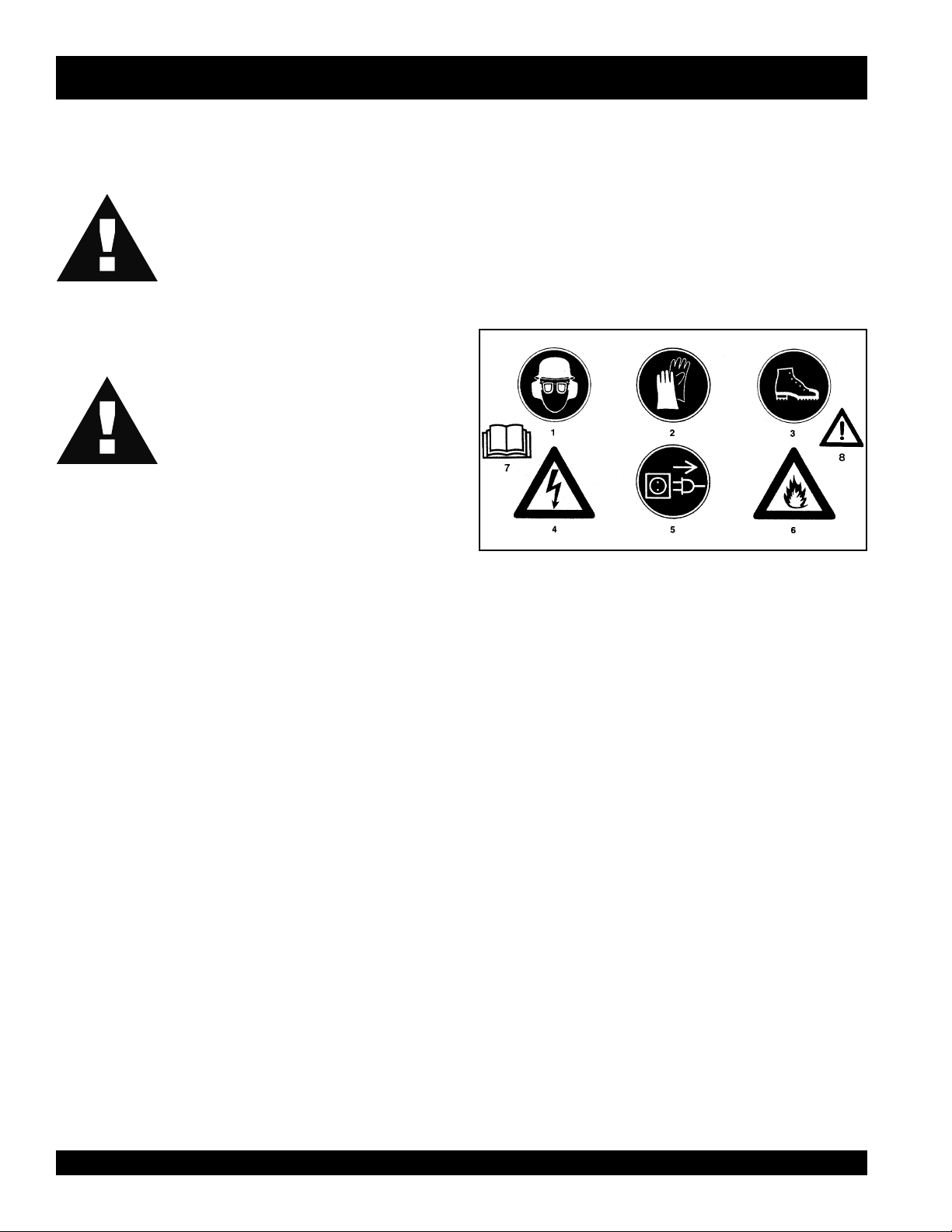
Explanation of the utilized safety symbols.
■
Disconnect the electrical supply to the Bullfloat, before you
start to clean or service the Bullfloat.
1. Safety glasses, safety helmet and ear protection
compulsory.
2. Gloves compulsory.
3. Safety shoes with extra protection compulsory.
4. Dangerous electrical voltage.
5. Before opening the motor housing remove the plug.
6. Inflammable material.
7. Pls. read the operation-instructions
8. Careful, danger!
Tip: Ask the manufacturer for clarification, if you have any
questions about any of these safety instructions.
PAGE 8 — Bullfloat HAL 150 & 300 — PARTS & OPERATION MANUAL — REV. #1 (05/27/99)
Page 9
SPECIFICATIONS
)CAV511(LAH )enigne-sagekorts2(LAH
egatloV
yticapaC
snoituloveR
lagufirtneC
ecrof
ssaM
leuF
erutxiM
gnilaeS
noitalusnI
rotoM
noitcetorp
ngiseD
CAV511
zH06/esahP1
W053 W025
nim/r00021 nim/r00021
).sbl504(N0081 ).sbl504(N0081
).sbl3.42()gK11(m1 ).sbl3.42()gK11(m1
).sbl6.82()gK31(m5,1 ).sbl6.82()gK31(m5,1
).sbl1.33()gK51(m2 ).sbl1.33()gK51(m2
).sbl5.73()gK71(m5,2 ).sbl5.73()gK71(m5,2
).sbl9.14()gK91(m3 ).sbl9.14()gK91(m3
— )erutxim(ekorts-2
— 52:1
foorphsalps,45PI foorphsalps,45PI
IIssalC
detalusnIelbuoD
foorpkcohsdnatcapmI —
elbatroP elbatroP
—
—
(11.8 in.)
(1.4 in.)
(11.8 in.)
(9.1 in.)
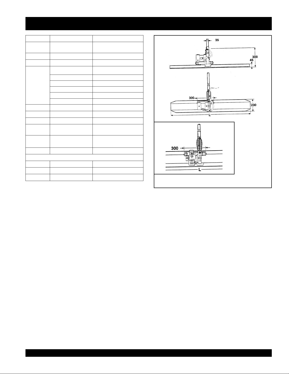
tinu-evirdsnoisnemiD
htgneL
htdiW
thgieH
).ni1.7(mm081 ).ni9.5(mm051
).ni9.5(mm051 ).ni9.7(mm002
).ni5.5(mm041 ).ni7.8(mm022
Figure 1.1
Dimensions in mm. of the HAL 150 & 300
Bullfloat HAL 150 & 300 — PARTS & OPERATION MANUAL — REV. #1 (05/27/99) — PAGE 9
Page 10
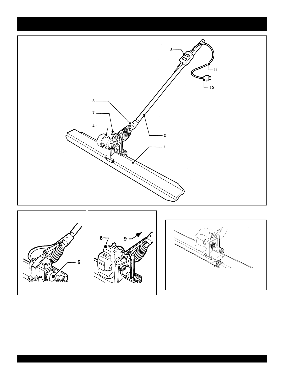
HAL 150 AND 300 — WHAT IS A BULLFLOAT
Figure 1.0
The bullfloat’s drive
1. Aluminium profile
2. Operating handle
3. Pitch control
4. Drive-unit 115 VAC
5. Vibratory Unit
6. Gas engine
7. Grip
8. ON/OFF-switch
9. Gas throttle
10. Plug
11. Cable
PAGE 10 — Bullfloat HAL 150 & 300 — PARTS & OPERATION MANUAL — REV. #1 (05/27/99)
Page 11

HAL 150 AND 300 — WHAT IS A BULLFLOAT
What is a Bullfloat?
A Bullfloat is an apparatus with a vibrating alloy blade that
smooths and compacts the top layer of freshly poured
concrete, without the need for guiding rails.
Before the Bullfloat is brought into action, the concrete should
be distributed and compacted by means of a vibrator.
The vibrator is used in combination with a laser, in order to
adjust and control the height of the concrete floor.
The Bullfloat consists of an operating handle, an electrical or
gas-engine vibrating-unit and an aluminium blade, available
in 5 lengths: 1m, 1.5m, 2m, 2.5m, and 3m.
The switch is located on the operating handle with which the
electrical vibrating-unit is switched ‘ON’ and ‘OFF’. The gas-
engine vibrating-unit is operated by means of a gas throttle
also located on the operating handle.
Operation
The drive-unit of the Bullfloat is started by turning the knob of
the electric-speed-regulator to the ‘ON’ position (electrical), or
by pulling the recoil-starter of the gas-engine.
An excentric part is set in motion by the drive-shaft of the motor.
This rotating motion sets the aluminium blade in vibration. The
vibrating motion of the blade smooths and compacts the
surface of the concrete.
Bullfloat HAL 150 & 300 — PARTS & OPERATION MANUAL — REV. #1 (05/27/99) — PAGE 11
Page 12
HAL 150 AND 300 — OPERATION
This section describes the operation of the HAL 150 &
300 Bullfloats.
Tip: For the location and description of the Bullfloat’s parts,
which are mentioned in the text, refer to the illustration figure
(page. 9): What is a Bullfloat.
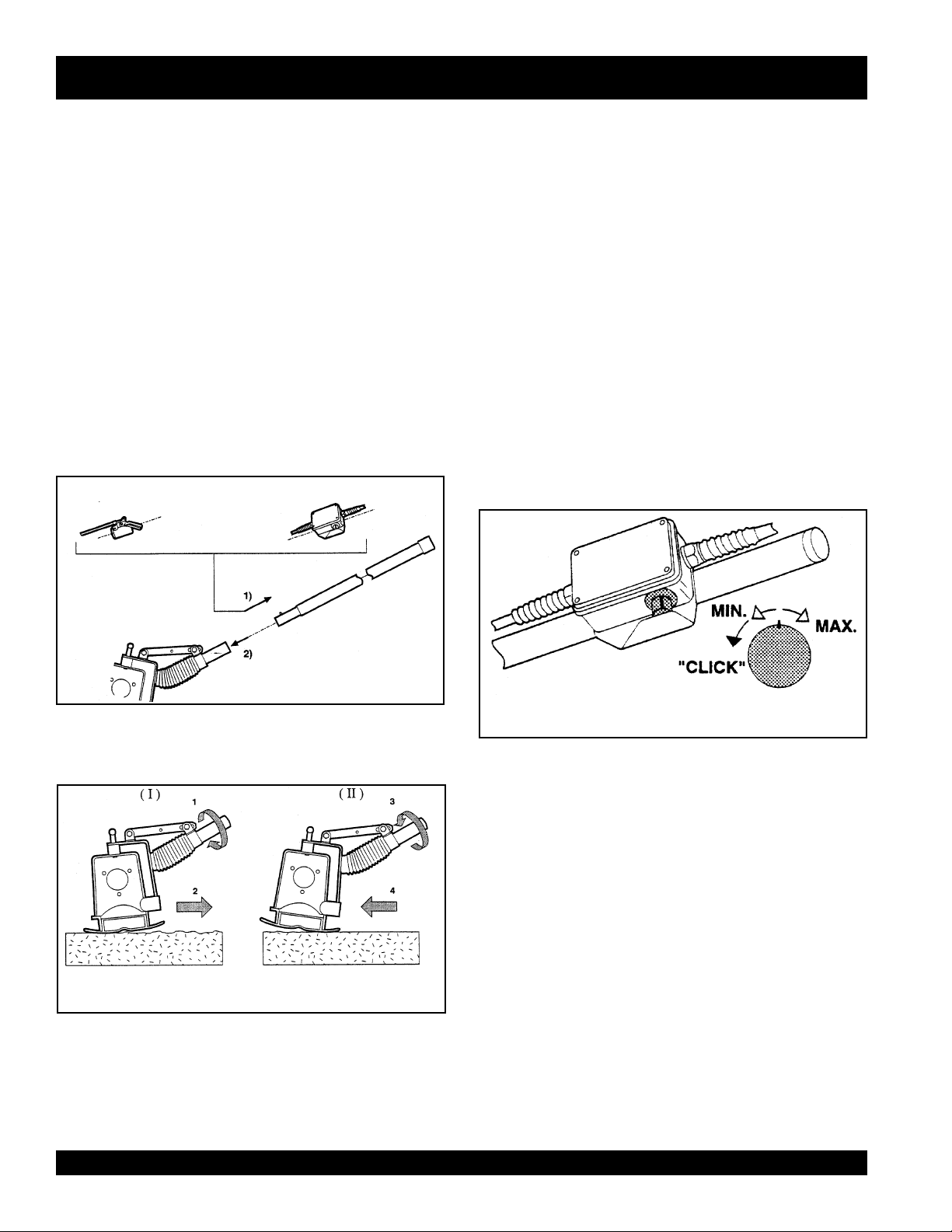
How to assemble the HAL 150 & 300 Bullfloats.
When delivered the Bullfloat is not ready for use.You only have
to carry out the following procedures to assemble them:
1. Connect the switch (an electronic speed regulator, or a
gas throttle), to the operating handle by means of the
bracket and the butterfly nut. Now lock the bracket by
tightning the butterfly nut. (Fig. No. 2.0)
2. Stick the operating handle into the shaft of the motor unit
frame.Make sure that the operating handle is locked
properly.
GAS ELECTRIC
Operation and use of the Bullfloat
This section describes how to operate and use the Bullfloat.In
the text are numbers in brackets. These numbers are position
numbers and they correspond to the numbers in the parts list
of the corresponding figures.
Careful: Read the safety instructions before you switch
on the apparatus.
Careful: Prevent the Bullfloat, from sinking into the concrete.
After the motor has been switched on, immediately move the
Bullfloat backwards.
Tip: Before the Bullfloat is brought into action, first compact
the freshly poured concrete floor with a poker-vibrator while at
the same time adjust the height of the floor by means of a
laser device.
Tip: Pour concrete lanes of approx. 3 ft. wide and approx. 15
ft. long. You can finish this surface in one pass without any
problem.
Figure 2.0
Assembly of the controls
How to adjust the trowel blade angle.
Figure 2.1
Adjusting the blade-pitch
Use position (I), when smoothing freshly poured concrete.
(Fig. No. 2.1)
Use position (II), in the event you want to smooth the same
lane once again.(Fig. No. 2.1)
Tip: When using a low slump concrete, move the Bullfloat
slowly across the surface of the concrete. When using a high
slump concrete, move the Bullfloat faster across the surface
of the concrete.
Figure 2.2
Types of switches
PAGE 12 — Bullfloat HAL 150 & 300 — PARTS & OPERATION MANUAL — REV. #1 (05/27/99)
Page 13

HAL 150 AND 300 — OPERATIONS
Operation of the Electric Bullfloat
1. Check that the Bullfloat is properly assembled and that
the switch is in the ‘OFF’ position.
2. Put the plug of the drive-unit’s feeder cable in the wall
socket.
3. Place the Bullfloat in the direct vicinity of where you are
going to smooth the surface of the concrete-floor.
4. Place the Bullfloat on the surface of the freshly poured
concrete, and turn the speed regulator slowly to the
required revolutions.
5. Adjust the trowel blade angle.(read paragraph 2, on page
11)
6. Now start to smooth the surface of the concrete floor by
moving the Bullfloat backwards in a slow but steady
motion.
7. After having finished one lane of concrete, switch off the
Bullfloat immediately, by turning the speed regulator’s
knob to the position ‘Minimal’. You will hear a “CLICK”.
(Fig. 2.2, on page 11)
Operation of the Gas Bullfloat
a. Throttle cable
b. Spark plug
c. Overflow pipe
d. Starter rope
e. Fuel cap and fuel filter
f. Fuel tank
g. Air filter
Figure 2.4
Components of the gas-engine
h. Carburetor
Figure 2.3
Work situation during smoothing and
compacting of the concrete floor.
Tip: If the processed concrete-surface is
enough, repeat the procedures 5
8. Pull the plug of the feeder cable out of the wall socket.
9. After use, place the Bullfloat on a dry and stable surface.
,6,7 and 8.
not smooth
or level
Bullfloat HAL 150 & 300 — PARTS & OPERATION MANUAL — REV. #1 (05/27/99) — PAGE 13
Page 14

HAL 150 AND 300 — OPERATIONS
Starting Procedure
1. Check that the Bullfloat is properly assembled, and the
fuel tank is filled.
2. Place the Bullfloat in the direct vicinity of where your are
going to smooth the surface of the concrete.
3. Adjust the throttle-lever (1) to the idle-position.(Fig 2.5)
Figure 2.5
Idle position of the throttle-handle and
components of the carburator
10. After allowing a three-minute warming-up period set the
Smoothing concrete
11. Adjust the right trowel blade angle. (read paragraph 2,
12. Smooth the freshly poured concrete.
Tip: Repeat procedure 12 in the event the treated surface is
not smooth or level enough.
13. Switch “off” the Bullfloat after you have finished the
throttle handle to the desired engine speed. The Bullfloat
is now ready for use.
page 11)
concrete lane:
— Put the throttle lever (1) in the idle position. (Fig 2.5)
4. Put the choke-lever (2) in the upper position.(Fig 2.5)
5. Push simultaneously the black priming pump (3) and the
tickler lever (4) (Fig 2.5) until fuel comes out of the
overflow pipe (c). (Fig 2.4)
Careful! : When pushing the tickler lever (4) half way down,
create
the fuel will flow directly into the engine and will
sure
problems. Be
Careful! : Never change the adjustment of the main jet screw
on the carburetor
6. Open the throttle-handle half way.
7. Give the starter rope (6) (Fig 2.6) a rapid vigorous pull
until the engine fires.
WARNING:
might break. Use 3/4 of the starter rope’s length.
8. If you have executed the starting procedure in the correct
Do not pull the starter rope all the way. The rope
way, the engine will run after approx. 2 pulls of the starter
rope.
to push the tickler lever fully down.
(5).(Fig 2.5)
starting
Location of the starter rope and the stop button
14. If you do not expect to use the engine for a long period
15. After use, place the Bullfloat on a dry and clean surface.
WARNING! Make sure to refill the fuel tank before you run out
of fuel during operation. Do not let the engine run until all the
fuel is used. This might cause starting problems. The average
operation time is approx. 45 min. (per tank).
Figure 2.6
— Press the black stop-button (7) for a couple of
seconds until the engine stops. (Fig 2.6)
of time, drain the fuel tank of fuel and let the engine run
at idle speed until the fuel in the carburetor is used and
the engine stops.
9. Allow the engine to run for approx. 10 seconds. Push the
choke lever (2) (Fig 2.5) slowly down. The period of time
depends on the ambient temperature.
PAGE 14 — Bullfloat HAL 150 & 300 — PARTS & OPERATION MANUAL — REV. #1 (05/27/99)
Page 15

HAL 150 AND 300 — TROUBLE SHOOTING
Problem: The Bullfloat does not vibrate in the ON position.
Cause: Fault in the electrical connections of the feeder
cable.
Solution: Check the electrical connections to the
Bullfloat, switch, plug and feeder cable for breakage.
Replace the faulty part(s).
Problem: The Bullfloat does not get into the required
number of revolutions.
Cause: Voltage drop, due to the feeder cable being too
long.
Solution: Move the electrical source closer to the
working area. Be certain you have the correct wire gauge
size for the distance and amp draw.
Problem: The electrical motor rotates irregularly and
makes a lot of noise.
Cause:
1. The bearings are worn out, and/or
2. an electrical defect in the stator, and/or
3. a break in the feeder cable.
Solution:
1. Replace the bearings, and/or
2. replace the stator, and/or
3. repair or replace the feeder cable.
Problem: Gas engine does not start.
Problem: The engine starts but runs irregularly.
Problem:The engine runs in idle position but stops when
increasing the revolutions.
Problem: Engine smokes excessively.
Cause: There is no, or too little, fuel in the fuel tank. The
starting procedure was not carried out in the correct way.
Solution: Fill the fuel tank or repeat the starting
procedure.
Cause: The spark plug, the fuel filter or the air filter are
dirty.
Solution: Clean or replace the spark plug, the fuel filter
or the air filter. See paragraph 4-4 on the next page.
Cause: The choke lever has not been pushed down
completely, after the starting procedure.
Solution: Repeat the starting procedure. (Do not prime
again). See Section 3, 4 & 5 on page 13.
Cause:
1. Choke lever has not been pushed down all the way.
2. The carburetor is worn out.
3. The engine is worn out.
4. Wrong mixture. (Possibly to much oil)
Solution:
Problem: The connected and running Bullfloat rotates
irregularly and does not get into the required revolutions.
Cause: Insufficient current supply.
Solution:
Electrical supply via electrical mains; check the plug
connections for defects.
Problem: The electrical motor runs irregularly.
Cause: The carbon brushes are worn out.
Solution: Replace the carbon brushes. (Replace every
6-12 months).
1. Check the position of the choke lever.
2. Replace the worn out parts of the carburetor, (please
consult your dealer or the manufacturer).
3. Replace the gas engine.
4. Replace the mixture for the right mixture with the
correct proportion: 1 part 2-stroke oil to 25 parts of
normal gasoline (1: 25).
Bullfloat HAL 150 & 300 — PARTS & OPERATION MANUAL — REV. #1 (05/27/99) — PAGE 15
Page 16

HAL 150 AND 300 — MAINTENANCE AND REPAIR
Maintenance
Although the Bullfloat has few moving parts, regular
maintenance promotes a long and trouble-free life.
Warning: Never use a high pressure cleaner to clean a
Bullfloat with an electrical or gas drive unit.
Lubricating the blade pitch control
Lubricate the blade pitch control, after long periods of storage,
or at least twice a year, by using a hand grease gun. (Fig. 4.0)
Figure 4.0
Lubricating the blade pitch control
Maintenance after 20 hours of operation
— How to clean the fuel filter.
1. Remove the fuel tank cap.
2. Pull out the black rubber tube from the fuel tank. At the
end of the tube is the felt-weight assembly. Remove the
felt and the felt-weight from the tube and wash out both
parts in clean fuel.
3. Insert the felt and the felt-weight into the fuel tank again.
How to clean the air filter.
1. Unscrew the black filter cap from the carburator.
2. Take out the filter element.
3. Wash out the filter element in clean fuel and wring
4. Re-install the filter and the black filter cap.
(Removal Procedure)
out the filter element.
4.3 Cleaning and servicing of the electrical drive unit.
Warning: Cut off the electrical supply to the Bullfloat before
carrying out any maintenance activities to the Bullfloat.
In order to achieve a maximum cooling effect the ventilation
slots of the electrical drive unit must stay free from dirt and
grease. Check them at the end of each working day.
If necessary, clean the motor with a brush or a damp cloth.
4.4 Cleaning and servicing of the gas engine. (refer also
to engine manual)
WARNING!: When the engine operates in dusty conditions,
clean the air filter each day or after each 10 hours of operation.
Daily maintenance
— In order to achieve a maximum cooling effect the
ventilation openings must stay free from dirt or grease.
Check them at the end of each working day.
If necessary, clean them with a brush or a damp cloth.
— For a proper functioning of the carburetor’s control
mechanism, it is necessary to check the carburetor for
concrete or dirt, each time after use. If necessary clean
the control mechanism with a brush or a damp cloth.
Figure 4.1
Location of the fuel and air filters
PAGE 16 — Bullfloat HAL 150 & 300 — PARTS & OPERATION MANUAL — REV. #1 (05/27/99)
Page 17

HAL 150 AND 300 — MAINTENANCE AND REPAIR
Maintenance after 50 hours of operation
■
Cleaning of the piston.
Remove the carbon from the upper side of the piston,
from the exhaust-ports in the cylinder, from the
combustion chamber and from the exhaust.
■
Cleaning of the spark plug.
Clean off carbon deposits on the spark plug electrode
using a plug cleaner or wire brush.
Check electrode gap. If necessary adjust it to between:
0.6 to 0.7 mm.
Longtime storage
1. Remove the spark plug and pour 3 to 5 cc of new
engine oil into the plug-hole.
Pull the recoil starter several times and reinstall the
spark plug.
2. Slowly pull the recoil starter until resistance is felt. The
piston is in its compression stroke.
3. Clean the engine thoroughly with an oiled cloth.
4. Store the engine in a clean and dry place.
Bullfloat HAL 150 & 300 — PARTS & OPERATION MANUAL — REV. #1 (05/27/99) — PAGE 17
Page 18

HAL 150 AND 300 FRAME
PAGE 18 — Bullfloat HAL 150 & 300 — PARTS & OPERATION MANUAL — REV. #1 (05/27/99)
Page 19

HAL 150 AND 300 FRAME
HAL 150 & 300 type E, ER and B frame
NO. PART NO. PART NAME QTY. REMARKS
1 BF230010 BLADE, ALUM. 1.0 m — 3 ft. 1
BF230015 BLADE, ALUM. 1.5 m — 5 ft. 1
BF230020 BLADE, ALUM. 2.0 m — 6½ ft. 1
BF230025 BLADE, ALUM. 2.5 m — 8 ft. 1
BF230030 BLADE, ALUM. 3.0 m — 10 ft. 1
3 BF23003 MOTOR ASSEMBLY BRACKET 1
4 BF0060 RUBBER BUFFER 3
5 BF0124 BOLT M8 X 10 5
6 BF0173 UNDULATED RING 2
7 BF0093 NUT M10 3
8 BF0115 BOLT M8 X 150 2
9 BF0107 NUT M8 2
10 BF0172 RETAINING RING 2
11 BF0156 WASHER M 10 4
31 BF230031 ASSEMBLY BRACKET 1
34 BF0140 BOLT 1
35 BF0212 RETAINING RING 1
36 BF23036 GRIP 1
37 BF23037 SPACER 1
49 BF2348 OPERATING HANDLE 150 CM 3
50 BF2350 PITCH CONTROL 1
51 BF23051 RUBBER SLEEVE 1
53 BF23053 ADJUSTABLE STRIP 1
54 BF0131 BOLT M10 X 25 2
56 BF23056 SPACER 4,2 mm 2
58 BF0203 LOCK-RING 2
59 BF23059 LUBRICATING NIPPLE & CAP 1
60 BF0133 BOLT M10 X 50 1
61 BF23061 SPACER 32 mm 1
63 BF23063 BRASS NUT M8 1
64 BF0125 BOLT M8 1
66 BF23066 PLASTIC CLAMP 1
68 BF23068 LOCKING CLIP 1
Bullfloat HAL 150 & 300 — PARTS & OPERATION MANUAL — REV. #1 (05/27/99) — PAGE 19
Page 20

HAL 150 AND 300 ELECTRIC DRIVE-UNIT AND SWITCH
22A
22
22B
22C
22D
73
PAGE 20 — Bullfloat HAL 150 & 300 — PARTS & OPERATION MANUAL — REV. #1 (05/27/99)
Page 21

HAL 150 AND 300 ELECTRIC DRIVE-UNIT AND SWITCH
HAL 150 & 300 type-E-,ER drive-unit and switch
NO. PART NO. PART NAME QTY. REMARKS
1 BF2301 N EXCENTER-HOUSING 1
2 BF2302N EXCENTER-SHAFT 1
6 BF2306B RUBBERSEAL 1
7 BF2307 ADAPTOR - BOLT (SHORT) 2
8 BF2308 ADAPTOR - BOLT (LARGE) 1
10 BF0155 WASHER 3
11 BF2311N COVER&BEARING, EXCENTER 1
12 BF231213 EXCENTER 1.0 - 1.5 m. 1
BF231217 EXCENTER 2.0 - 2.5 m. 1
13 BF0201 LOCKRING 1
14 BF2314 EXCENTER-BEARING 1
16 BF2316 O-RING 1
20 BF2320 DRIVE-UNIT 1
21 BF0051 RUBBERBUFFER 3
22 BF2325 COUPLING- SET 1 INCLS. ALL ITEMS W/
22A
*
22B
*
22C
*
22D
*
23 BF0172 RETAINING RING M8 3
24 BF0088 CAPNUT 2
29 BF0017 CABLE 2 X1,5 mm2 + PLUG 220V 10
33 BF0086 CAPNUT (HIGH) 1
35 BF2335 CABLE-CLAMP 1
44 BF0004 CABLE 1
69 BF2369ER SWITCH ASSEMBLY BRACKET (ER) 1
73 BF0325 WING-SCREW 1
74 BF23074 SWITCH COMPLETE 1
78 BF0122 SCREW 1
90 BF0420 PACKING BOX 2
91 BF0421 NUT 2
92 BF2392 SPEED-REGULATOR (ONLY) 1
93 BF2393 SWFTCH-BOX (SPEED-REGULATOR) 1
94 BF2394 POTENTIOMETER & SWITCH 1
95A BF2395A KNOB (POTENTIOMETER) 1
95B BF2395B KNOB-CAP 1
95C BF2395C FIGURE DIAL 1
95D BF2395D STATOR 1
97 BF2397 TERMINAL-BLOC 1
98 BF2398 SPEED-REGULATOR COMPL. (INCL. BRACKET) 1
99 BF2399 SPEED-REGULATOR COMPL. (EXCL. BRACKET) 1
BF2323 CATCH, DRIVESHAFT 1
BF0273 SCREW 1
BF0154 WASHER 1
BF2322 SPRING 1
*
Bullfloat HAL 150 & 300 — PARTS & OPERATION MANUAL — REV. #1 (05/27/99) — PAGE 21
Page 22

HAL 150 AND 300 ELETRIC DRIVE-UNIT COMPONENTS
PAGE 22 — Bullfloat HAL 150 & 300 — PARTS & OPERATION MANUAL — REV. #1 (05/27/99)
Page 23

HAL 150 AND 300 ELETRIC DRIVE-UNIT COMPONENTS
HAL 150 & 300 type- E, ER drive-unit
NO. PART NO. PART NAME QTY. REMARKS
3A BF2303A VENTILATION RING (SMALL) 1
3B BF2303B VENTILATION RING (LARGE) 1
3C BF2303C VENTILATION HOUSING 1
40 BF0428 RUBBERING 1
41 BF0421 PLASTIC NUT 1
42 BF0430 PACKING BOX 1
43 BF1101220240 REAR-BEARING 1
45S BF2345S STATOR 1
45R BF2345R ROTOR 1
46 BF2346 FRONT SHIELD 1
47 BF0249 SELF TAPPING SCREW 5
52 BF1101220170 VENTILATOR-COVER 1
53 BF1101220200 SCREW 2
54 BF1101220250 SPRING SOURCER 2
55 BF1101220220 BRUSH-COVER 2
56 BF1101220180 MOTOR-HOUSING 1
57 BF2357 CAPACITOR 1
58 BF2358 CAPACITOR-CLAMP 1
59 BF0248 SELF TAPPING SCREW 3
60 BF2360 TERMINAL-BLOC 1
61 BF1101220230' SET OF BRUSHES 1
62 BF0230 SELF TAPPING SCREW 3
63 BF0231 SELF TAPPING SCREW 3
64 BF0154 WASHER 3
65 BF0417 PRESSING RING 2
66 BF0415 CABLE-SLEEVE 1
67 BF0416 CABLE-PACKING-BOX 1
Bullfloat HAL 150 & 300 — PARTS & OPERATION MANUAL — REV. #1 (05/27/99) — PAGE 23
Page 24

HAL 150 AND 300 GAS DRIVE-UNIT AND GAS THROTTLE
22A
22
22B
22C
22D
PAGE 24 — Bullfloat HAL 150 & 300 — PARTS & OPERATION MANUAL — REV. #1 (05/27/99)
Page 25

HAL 150 AND 300 GAS DRIVE-UNIT AND GAS THROTTLE
HAL 150 & 300 type- B drive-unit and gasthrottle
NO. PART NO. PART NAME QTY. REMARKS
1 BF2301 N EXCENTER-HOUSING 1
2 BF2302N EXCENTER-SHAFT 1
6 BF2306 B SEAL, RUBBER 1
7 BF2307 ADAPTOR-BOLT (SHORT) 2
8 BF2308 ADAPTOR-BOLT (LARGE) 1
10 BF0155 WASHER 3
11 BF2311N COVER&BEARING (EXCENTER HS.) 1
12 BF231213 EXCENTER 1.0 - 1.5 m. 1
BF231217 EXCENTER 2.0 - 2.5 m. 1
13 BF0201 LOCK RING 1
14 BF2314 EXCENTER-BEARING 1
16 BF2316 O-RING 1
18 BF2318N ENGINE BRACKET 1
20 BF2302666020 GAS ENGINE, KAWASKI 1
20A BF2320A ENGINE ADAPTOR 1
21 BF0055 RUBBER BUFFER 3
22 BF2325 COUPLING - SET 1 INCLS. ALL ITEMS W/
22A
*
22B
*
22C
*
22D
*
23 BF0172 RETAINING RING M8 3
24 BF0088 CAPNUT 2
28 BF2328 SPACER 3
33 BF0086 CAPNUT (HIGH) 1
69 BF2369B LEVER, GAS & BRACKET 1
70 BF2302666700 LEVER, GAS (ONLY) 1
71 BF2371 THROTTLE-CABLE (OUTER) 1
72 BF2372 THROTTLE-CABLE (INNER) 1
73 BF0325 WING-SCREW 1
75 BF2375 ASSEMBLY-BRACKET 1
76 BF2376 THROTTLE-CABLE STOPPER 1
78 BF0122 SCREW 1
79 BF0123 NUT 4
83 BF2383 SPRING 1
84 BF2384 DRIVE-SHAFT ASSY 1
BF2323 CATCH, DRIVESHAFT 1
BF0273 SCREW 1
BF0154 WASHER 1
BF2322 SPRING 1
BF23510 UNIT ASSY (ENGINE & COMPONENTS), KAWASAKI 1
*
KWAAIR ELEMENT, AIR FILTER KAWASAKI ENGINE 1
0650140460 SPARK PLUG, KAWASAKI ENGINE 1
NOTE: For the balance of the Kawaski Engine Parts, call your local Kawaski Engine
distributor refering to engine model TGO 18D-CA 51
For the Robin Engine spare parts, refer to the engine section of this book.
Bullfloat HAL 150 & 300 — PARTS & OPERATION MANUAL — REV. #1 (05/27/99) — PAGE 25
Page 26

ROBIN EC0250G6004 — CRANKCASE & CYLINDER
PAGE 26 — Bullfloat HAL 150 & 300 — PARTS & OPERATION MANUAL — REV. #1 (05/27/99)
Page 27

ROBIN EC0250G6004 — CRANKCASE & CYLINDER
CRANKCASE & CYLINER
NO. PART NO. PART NAME QTY. REMARKS
10 525100300 CRANKCASE ASSY 1 INCLS. ITEMS W/
15 5231502202 GASKET 1
30
*
40
*
95 0140059520 SCREW 3
170 5231502304 GASKET 1
510 5251500200 CYLINDER 1
630 0119059730 SOCKET HEAD BOLT 2
0440129970 OIL SEAL 2
0600129920 BALL BEARING 2
*
Bullfloat HAL 150 & 300 — PARTS & OPERATION MANUAL — REV. #1 (05/27/99) — PAGE 27
Page 28

ROBIN EC0250G6004 — CRANKSHAFT & PISTON
PAGE 28 — Bullfloat HAL 150 & 300 — PARTS & OPERATION MANUAL — REV. #1 (05/27/99)
Page 29

ROBIN EC0250G6004 — CRANKSHAFT & PISTON
CRANKCASE & PISTON
NO. PART NO. PART NAME QTY. REMARKS
10 5252001001 CRANKSHAFT 1
55 0011306160 BOLT & WASHER ASSY 1
65 0031206000 WASHER 1
350 5232502600 PISTON PIN 1
360 5232501902 PISTON 1
370 5242500701 PISTON RING 1
380 0565089970 CLIP 2
390 0610089990 NEEDLE BEARINGS 1
Bullfloat HAL 150 & 300 — PARTS & OPERATION MANUAL — REV. #1 (05/27/99) — PAGE 29
Page 30

ROBIN EC0250G6004 — MUFFLER, AIR CLEANER
PAGE 30 — Bullfloat HAL 150 & 300 — PARTS & OPERATION MANUAL — REV. #1 (05/27/99)
Page 31

ROBIN EC0250G6004 — MUFFLER, AIR CLEANER
MUFFLER, AIR CLEANER
NO. PART NO. PART NAME QTY. REMARKS
310 5253015000 MUFFLER 1
320 5253500000 MUFFLER COVER 1
340 5233504302 GASKET 1
345 5253500101 GASKET 1
360 0119059660 SOCKET HEAD BOLT 2
370 0043705160 SCREW ASSY 1
510 5203004030 AIR CLEANER ASSY 1 INCLS. ITEMS W/
515
*
520
*
540 5233014000 INSULATOR CAP 1
550 5253500200 GASKET 1
560 5103502800 GASKET 1
562 5256501200 GASKET 1
563 5256501100 O’RING 1
580 0043305650 SCREW ASSY 2
581 0140059500 SCREW ASSY 2
5253004010 CLEANER BODY ASSY 1
5203004010 ELEMENT, AIR CLEANER 1
*
Bullfloat HAL 150 & 300 — PARTS & OPERATION MANUAL — REV. #1 (05/27/99) — PAGE 31
Page 32

ROBIN EC0250G6004 — RECOIL STARTER & HOUSING
PAGE 32 — Bullfloat HAL 150 & 300 — PARTS & OPERATION MANUAL — REV. #1 (05/27/99)
Page 33

ROBIN EC0250G6004 — RECOIL STARTER & HOUSING
RECOIL STARTER & HOUSING
NO. PART NO. PART NAME QTY. REMARKS
10 5255500001 BLOWER HOUSING 1
13 5215500300 BUFFLE PLATE 1
20 5259500000 DECAL 1
40 0043505160 SCREW AND WASHER ASSY 3
50 5255500401 CYLINDER COVER 1
51 0140059490 SCREW 1
52 0200070010 WASHER 1
55 5503503001 SPACER 1
210 5255001000 RECOIL STARTER ASSY 1 INCLS. ITEMS W/
213
*
214
*
215
*
216
*
217
*
218
*
219
*
220
*
221
*
222
*
230 0140059480 SCREW 1
5225004020 STARTER KNOB 1
5025001020 SPIRAL SPRING 1
5235024022 STARTER ROPE 1
5025001010 REEL 1
5255001020 SET SCREW 1
5215002040 FRICTION PLATE 1
5105015050 FRICTION SPRING 1
5105015020 RATCHET 1
5105015060 RETURN SPRING 1
5255001040 DAMPER 1
*
Bullfloat HAL 150 & 300 — PARTS & OPERATION MANUAL — REV. #1 (05/27/99) — PAGE 33
Page 34

ROBIN EC0250G6004 — CARBURETOR & FUEL TANK
PAGE 34 — Bullfloat HAL 150 & 300 — PARTS & OPERATION MANUAL — REV. #1 (05/27/99)
Page 35

ROBIN EC0250G6004 — CARBURETOR & FUEL TANK
FUEL TANK, CARBURETOR
NO. PART NO. PART NAME QTY. REMARKS
10 5256500502 FUEL TANK 1
20 5259503500 LABEL, MODEL 1
30 5216004003 CAP 1
35 0043705160 SCREW ASSY 4
40 5236503900 FILTER 1
65 5256012001 TUBE ASSY 1
140 5256002000 PLATE 1
145 0230059970 SPACER 2
147 0230059950 SPACER 1
210 5256007000 CARBURETOR ASSY 1 INCLS. ITEMS W/
227
232
233
234
235
236
237
246
247
253
254
255
256
350
355
357
360
*
*
*
*
*
*
*
*
*
*
*
*
*
*
*
*
*
5236046050 SPACER 1
5246001030 COVER 1
5246001040 DIAPHRAGM 1
5316005250 DIAPHRAGM ASSY 1
5236046040 GASKET 1
5246001150 PUMP 1
5236046010 SCREW 4
5256007010 BODY ASSY 1
5016004010 SCREEN 1
5236046060 BODY ASSY 1
5316005120 RING 1
5236018040 SWIVEL 1
5206008030 SCREW 2
5256500100 CABLE BRACKET 1
5216008010 ADJUSTER SCREW 1
5316005150 NUT 1
5219500000 HOLDER 1
*
Bullfloat HAL 150 & 300 — PARTS & OPERATION MANUAL — REV. #1 (05/27/99) — PAGE 35
Page 36

ROBIN EC0250G6004 — COIL & SPARK PLUG
PAGE 36 — Bullfloat HAL 150 & 300 — PARTS & OPERATION MANUAL — REV. #1 (05/27/99)
Page 37

ROBIN EC0250G6004 — COIL & SPARK PLUG
COIL & SPARK PLUG
NO. PART NO. PART NAME QTY. REMARKS
10 5257001010 FLYWHEEL 1
11 5257001020 IGNITION COIL 1
35 0140049920 SCREW 2
60 0660000371 SWITCH ASSY 1
70 0043304100 SCREW & WASHER ASSY 2
81 5257500300 GROMMET 1
95 0654009931 SPRING, PLUG CAP 1
100 0650149721 SPARK PLUG 1
110 5237503301 SPARK PLUG CAP 1
Bullfloat HAL 150 & 300 — PARTS & OPERATION MANUAL — REV. #1 (05/27/99) — PAGE 37
Page 38

Effective: July 1, 2000
TERMS AND CONDITIONS OF SALE — PARTS
PAYMENT TERMS
Terms of payment for parts are net 10 days.
FREIGHT POLICY
All parts orders will be shipped collect or
prepaid with the charges added to the invoice.
All shipments are F.O.B. point of origin.
Multiquip’s responsibility ceases when a
signed manifest has been obtained from the
carrier, and any claim for shortage or damage
must be settled between the consignee and the
carrier.
MINIMUM ORDER
The minimum charge for orders from Multiquip
is $15.00 net. Customers will be asked for
instructions regarding handling of orders not
meeting this requirement.
RETURNED GOODS POLICY
Return shipments will be accepted and credit
will be allowed, subject to the following
provisions:
1. A Returned Material Authorization must
be approved by Multiquip prior to shipment.
2. To obtain a Return Material Authorization,
a list must be provided to Multiquip Parts
Sales that defines item numbers,
quantities, and descriptions of the items
to be returned.
a. The parts numbers and descriptions
must match the current parts price
list.
b. The list must be typed or computer
generated.
c. The list must state the reason(s) for
the return.
d. The list must reference the sales
order(s) or invoice(s) under which
the items were originally purchased.
e. The list must include the name and
phone number of the person
requesting the RMA.
3. A copy of the Return Material
Authorization must accompany the return
shipment.
4. Freight is at the sender’s expense. All
5. Parts must be in new and resalable
6. The following items are not returnable:
7. The sender will be notified of any material
8. Such material will be held for 5 working
9. Credit on returned par ts will be issued at
10. In cases where an item is accepted for
11. Credit issued will be applied to future
PRICING AND REBATES
parts must be returned freight prepaid to
Multiquip’s designated receiving point.
condition, in the original Multiquip package
(if any), and with Muiltiquip part numbers
clearly marked.
a. Obsolete parts. (If an item is listed
in the parts price book as being
replaced by another item, it is
obsolete.)
b. Any parts with a limited shelf life
(such as gaskets, seals, “O” rings,
and other rubber parts) that were
purchased more than six months
prior to the return date.
c. Any line item with an extended dealer
net price of less than $5.00.
d. Special order items.
e. Electrical components.
f. Paint, chemicals, and lubricants.
g. Decals and paper products.
h. Items purchased in kits.
received that is not acceptable.
days from notification, pending
instructions. If a reply is not received
within 5 days, the material will be returned
to the sender at his expense.
dealer net price at time of the original
purchase, less a 15% restocking charge.
which the original purchase document
can not be determined, the price will be
based on the list price that was effective
twelve months prior to the RMA date.
purchases only.
Prices are subject to change without prior
notice. Price changes are effective on a specific
date and all orders received on or after that date
will be billed at the revised price. Rebates for
price declines and added charges for price
increases will not be made for stock on hand
at the time of any price change.
Multiquip reserves the right to quote and sell
direct to Government agencies, and to Original
Equipment Manufacturer accounts who use
our products as integral parts of their own
products.
SPECIAL EXPEDITING SERVICE
A $20.00 to $50.00 surcharge will be added to
the invoice for special handling including bus
shipments, insured parcel post or in cases
where Multiquip must personally deliver the
parts to the carrier.
LIMITATIONS OF SELLER’S LIABILITY
Multiquip shall not be liable here under for
damages in excess of the purchase price of the
item with respect to which damages are
claimed, and in no event shall Multiquip be
liable for loss of profit or good will or for any
other special, consequential or incidental
damages.
LIMITATION OF WARRANTIES
No warranties, express or implied, are made
in connection with the sale of parts or trade
accessories nor as to any engine not
manufactured by Multiquip. Such warranties
made in connection with the sale of new,
complete units are made exclusively by a
statement of warranty packaged with such
units, and Multiquip neither assumes not
authorizes any person to assume for it any
other obligation or liability whatever in
connection with the sale of its products. A part
from such written statement of warranty, there
are no warranties, express, implied or statutory,
which extend beyond the description of the
products on the face hereof.
PAGE 38 — Bullfloat HAL 150 & 300 — PARTS & OPERATION MANUAL — REV. #1 (05/27/99)
Page 39

NOTE PAGE
Bullfloat HAL 150 & 300 — PARTS & OPERATION MANUAL — REV. #1 (05/27/99) — PAGE 39
Page 40

PARTS AND OPERATION MANUAL
HERE'S HOW TO GET HELP
PLEASE HAVE THE MODEL AND SERIAL NUMBER
ON-HAND WHEN CALLING
PARTS DEPARTMENT
800-427-1244 or 310-537-3700
FAX: 800-672-7877 or 310-637-3284
SERVICE DEPARTMENT/TECHNICAL ASSISTANCE
800-478-1244 or 310-537-3700
FAX: 310- 537-4259
WARRANTY DEPARTMENT
888-661-4279, or 310-661-4279
FAX: 310- 537-1173
MAIN
800-421-1244 or 310-537-3700
FAX: 310-537-3927
MULTIQUIP INC.
POST OFFICE BOX 6254
CARSON, CA 90749
310-537-3700 • 800-421-1244
FAX: 310-537-3927
E-MAIL: mq@multiquip.com
WWW: multiquip.com
Quebec, Canada • Manchester, UK • Rio De Janiero, BR • Guadalajara, MX
Atlanta • Boise • Dallas • Houston • Newark
 Loading...