

Page 1

OPERATION AND PARTS MANUAL
MODEL DSGPULW
DuoScreed LightWeight
(HONDA GX35SAT GASOLINE ENGINE)
Revision #6 (12/10/10)
To find the latest revision of this
publication, visit our website at:
www.multiquip.com
THIS MANUAL MUST ACCOMPANY THE EQUIPMENT AT ALL TIMES.
Page 2
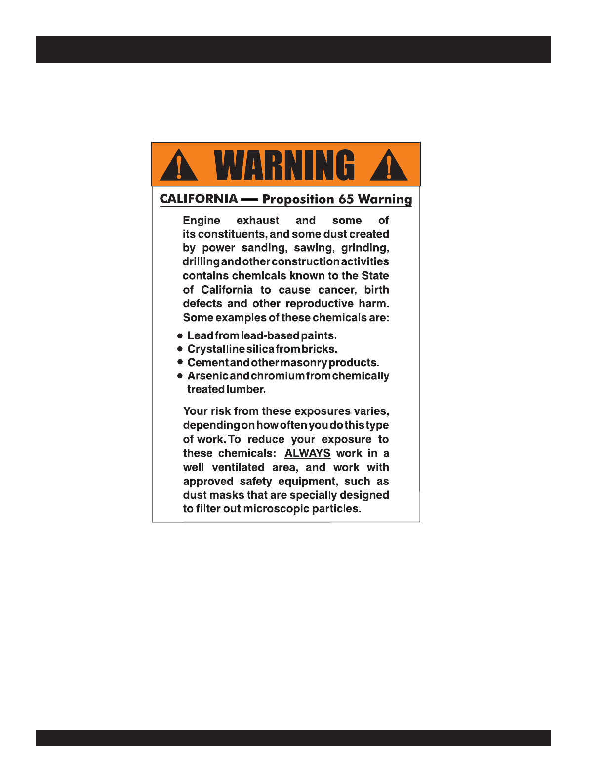
DSGPULW DUOSCREED — PROPOSITION 65 WARNING
l
PAGE 2 — DSGPULW DUOSCREED — OPERATION AND PARTS MANUAL — REV. #6 (12/10/10)
Page 3
DSGPULW DUOSCREED — SILICOSSIS WARNING
WARNING
SILICOSIS WARNING RESPIRATORY HAZARDS
Grinding/cutting/drilling of masonry, concrete, metal and
other materials with silica in their composition may give
off dust or mists containing crystalline silica. Silica is a
basic component of sand, quartz, brick clay, granite and
numerous other minerals and rocks. Repeated and/or
substantial inhalation of airborne crystalline silica can
cause serious or fatal respiratory diseases, including
silicosis. In addition, California and some other
authorities have listed respirable crystalline silica as a
substance known to cause cancer. When cutting such
materials, always follow the respiratory precautions
mentioned above.
WARNING
Grinding/cutting/drilling of masonry, concrete, metal and
other materials can generate dust, mists and fumes
containing chemicals known to cause serious or fatal
injury or illness, such as respiratory disease, cancer,
birth defects or other reproductive harm. If you are
unfamiliar with the risks associated with the particular
process and/or material being cut or the composition of
the tool being used, review the material safety data
sheet and/or consult your employer, the material
manufacturer/supplier, governmental agencies such as
OSHA and NIOSH and other sources on hazardous
materials. California and some other authorities, for
instance, have published lists of substances known to
cause cancer, reproductive toxicity, or other harmful
effects.
Control dust, mist and fumes at the source where
possible. In this regard use good work practices and
follow the recommendations of the manufacturers or
suppliers, OSHA/NIOSH, and occupational and trade
associations. Water should be used for dust
suppression when wet cutting is feasible. When the
hazards from inhalation of dust, mists and fumes cannot
be eliminated, the operator and any bystanders should
always wear a respirator approved by NIOSH/MSHA for
the materials being used.
DSGPULW DUOSCREED — OPERATION AND PARTS MANUAL — REV. # 6 (12/10/10) — PAGE 3
Page 4

DSGPULW DUOSCREED —TABLE OF CONTENTS
Multiquip DS-Series —
Vibratory DuoScreed
Here's How To Get Help ............................................ 3
Table Of Contents ..................................................... 4
Parts Ordering Procedures ....................................... 5
Rules For Safe Operation ...................................... 8-9
Operation and Safety Decals .................................. 10
Specifications .......................................................... 11
General Information ................................................ 12
Components (DuoScreed) ...................................... 13
Components (Honda GX35SAT Engine) ................. 14
Assembly Instructions ........................................ 15-17
Starting ................................................................... 18
Application/Operation......................................... 19-22
Maintenance ...................................................... 23-24
Troubleshooting (DuoScreed) ................................. 25
Troubleshooting (Honds GX35SAT Engine) ............ 26
Explanation Of Codes In Remarks Column ............ 28
Suggested Spare Parts ........................................... 29
Nameplate and Decals....................................... 30-31
Main Assembly ................................................... 32-35
Blade Assembly ................................................. 36-37
Honda GX35SAT Engine
Air Cleaner Assembly .........................................38-39
Cam Pulley Assembly ........................................ 40-41
Carburetor Assembly ......................................... 42-43
Crankcase Assembly ......................................... 44-45
Crankshaft and Piston Assembly ......................46-47
Fan Cover and Clutch/Assembly........................ 48-49
Recoil Starter Assembly.....................................50-51
Flywheel and Ignition Coil Assembly .................52-53
Fuel Tank ............................................................ 54-55
Muffler Assembly ...............................................56-57
Engine Top Cover Assembly .............................. 58-59
Labels ................................................................60-61
Terms and Conditions Of Sale — Parts .................. 62
NOTE
PAGE 4 — DSGPULW DUOSCREED — OPERATION AND PARTS MANUAL — REV. #6 (12/10/10)
Specification and part
number are subject to
change without notice.
l
Page 5
DSGPULW DUOSCREED — PARTS ORDERING PROCEDURES
Ordering parts has never been easier!
Choose from three easy options:
January 1
Effective:
st
, 2006
Best Deal!
Order via Internet (Dealers Only):
Order parts on-line using Multiquip’s SmartEquip website!
N View Parts Diagrams
N Order Parts
N Print Specification Information
Goto www.multiquip.com and click on
Order Par ts
Order via Fax (Dealers Only):
All customers are welcome to order parts via Fax.
Domestic (US) Customers dial:
1-800-6-PARTS-7 (800-672-7877)
Non-Dealer Customers:
Contact your local Multiquip Dealer for
parts or call 800-427-1244 for help in
locating a dealer near you.
to log in and save!
Order via Phone:
If you have an MQ Account, to obtain a Username
and Password, E-mail us at: parts@multiquip.
com.
To obtain an MQ Account, contact your
District Sales Manager for more information.
Use the internet and qualify for a 5% Discount
on Standard orders for all orders which include
complete part numbers.*
Note: Discounts Are Subject To Change
Fax your order in and qualify for a 2% Discount
on Standard orders for all orders which include
complete part numbers.*
Note: Discounts Are Subject To Change
Domestic (US) Dealers Call:
1-800-427-1244
International Customers should contact
their local Multiquip Representatives for
Parts Ordering information.
When ordering parts, please supply:
R Dealer Account Number
R Dealer Name and Address
R Shipping Address (if different than billing address)
R Return Fax Number
R Applicable Model Number
R Quantity, Part Number and Description of Each Part
NOTICE
All orders are treated as Standard Orders and will
ship the same day if received prior to 3PM PST.
R Specify Preferred Method of Shipment:
UPS/Fed Ex DHL
N Priority One Tr uck
N Ground
N Next Day
N Second/Third Day
www.multiquip.com
WE ACCEPT ALL MAJOR CREDIT CARDS!
DSGPULW DUOSCREED — OPERATION AND PARTS MANUAL — REV. # 6 (12/10/10) — PAGE 5
Page 6
DSGPULW DUOSCREED — SAFETY MESSAGE ALERT SYMBOLS
FOR YOUR SAFETY AND THE SAFETY OF OTHERS!
Safety precautions should be followed at all times when operating
this equipment. Failure to read and understand the Safety
Messages and Operating Instructions could result in injury to
yourself and others.
This Owner's Manual has been
developed to provide complete
NOTE
Before using this screed, ensure that the operating
individual has read and understands all instructions in this
manual.
instructions for the safe and
efficient operation of the Multiquip
Model DSGPULW LightWeight
(LW) DuoScreed
engine manufacturers instructions
for data relative to its safe
operation.
Refer to the
HAZARD SYMBOLS
SAFETY MESSAGE ALERT SYMBOLS
The three (3) Safety Messages shown below will inform you
about potential hazards that could injure you or others. The
Safety Messages specifically address the level of exposure to
the operator, and are preceded by one of three words: DANGER,
WARNING, or CAUTION.
Lethal Exhaust Gases
Engine exhaust gases contain poisonous
carbon monoxide. This gas is colorless and
odorless, and can cause death if inhaled.
NEVER operate this equipment in a confined
area or enclosed structure that does not
provide ample free flow air.
Explosive Fuel
GASOLINE is extremely flammable, and its
vapors can cause an explosion if ignited. DO
NOT start the engine near spilled fuel or
combustible fluids. DO NOT fill the fuel tank
while the engine is running or hot. DO NOT
overfill tank, since spilled fuel could ignite if it
comes into contact with hot engine parts or
sparks from the ignition system. Store fuel in
approved containers, in well-ventilated areas
and away from sparks and flames. NEVER
use fuel as a cleaning agent.
DANGERDANGER
DANGER
DANGERDANGER
You WILL be
if you DO NOT follow these directions.
WARNINGWARNING
WARNING
WARNINGWARNING
You CAN be KILLED or
you DO NOT follow these directions.
CAUTICAUTI
CAUTION
CAUTICAUTI
You CAN be
these directions.
Potential hazards associated with the MQ DSGPULW DuoScreed
operation will be referenced with Hazard Symbols which appear
throughout this manual, and will be referenced in conjunction
with Safety Message Alert Symbols.
KILLED
INJURED
if you DO NOT follow
or
SERIOUSLY INJURED
l
SERIOUSLY INJURED
if
Burn Hazards
Engine components can generate extreme heat.
To prevent burns, DO NOT touch these areas
while the engine is running or immediately after
operations. Never operate the engine with heat
shields or heat guards removed.
Rotating Parts
NEVER operate equipment with covers, or
guards removed. Keep fingers, hands, hair and
clothing away from all moving parts to prevent
injury.
PAGE 6 — DSGPULW DUOSCREED — OPERATION AND PARTS MANUAL — REV. #6 (12/10/10)
Page 7
DSGPULW DUOSCREED — SAFETY MESSAGE ALERT SYMBOLS
Accidental Starting
ALWAYS place the engine ON/OFF switch in
the OFF position when the DuoScreed is not
in use.
Sight and Hearing hazard
ALWAYS wear approved eye and hearing
protection.
Respiratory Hazard
ALWAYS wear approved respiratory
protection.
Equipment Damage Messages
Other important messages are provided throughout this manual
to help prevent damage to your DuoScreed, other property, or
the surrounding environment.
NOTE
This DuoScreed, other property,
or the surrounding environment
could be damaged if you do not
follow instructions.
DSGPULW DUOSCREED — OPERATION AND PARTS MANUAL — REV. # 6 (12/10/10) — PAGE 7
Page 8
DSGPULW DUOSCREED — RULES FOR SAFE OPERATION
■
DANGER - READ THIS MANUAL!
Failure to follow instructions in this manual may lead to
serious injury
operated by trained and qualified personnel only! This
equipment is for industrial use only.
The following safety guidelines should always be used when
operating the
General Safety:
■
DO NOT operate or service this
equipment before reading this entire
manual.
The operator MUST BE familiar with proper safety
precautions and operations techniques before using
generator.
■
This equipment should not be operated by persons under
18 years of age.
■
NEVER operate this equipment without proper protective
clothing, shatterproof glasses, steel-toed boots and other
protective devices required by the job.
or even
DEATH
! This equipment is to be
MQ DSGPULW DuoScreed.
ALWAYS check the machine for loosened threads or bolts
before starting.
■
NEVER operate the DuoScreed in an explosive
atmosphere or near combustible materials. An explosion
or fire could result causing severe
death.
■
NEVER touch the hot exhaust manifold,
muffler or cylinder. Allow these parts
to cool before servicing engine or
generator.
■
High Temperatures – Allow the engine
to cool before performing service and
maintenance functions. Contact with
can cause serious burns.
■
The engine of the DuoScreed
requires an adequate free flow
of cooling air.
operate the DuoScreed in any
enclosed or narrow area where
free flow of the air is restricted.
If the air flow is restricted it
will cause serious damage to
the engine and may cause injury to people. The
DuoScreed's engine gives off DEADLY carbon monoxide
gas.
NEVER
bodily harm or even
hot!
components
■
NEVER operate this equipment when not
feeling well due to fatigue, illness or taking
medicine.
■
NEVER operate this equipment under the influence or
drugs or alcohol.
■
■
l
■
■
NEVER use accessories or attachments, which are not
recommended by Multiquip for this equipment. Damage
to the equipment and/or injury to user may result.
■
Manufacturer does not assume responsibility for any
accident due to equipment modifications. Unauthorized
equipment modification will void all warranties.
■
Whenever necessary, replace nameplate, operation and
safety decals when they become difficult read.
■
Always refuel in a well-ventilated area, away from sparks and
open flames.
Always use extreme caution when
working with flammable liquids. When
refueling, stop the engine and allow it
to cool. DO NOT
the machine. Fire or explosion could
result from fuel vapors, or if fuel is spilled
on a hot engine.
NEVER operate the DuoScreed in an explosive atmosphere
or near combustible materials. An explosion or fire could result
causing severe
Topping-off to filler port is dangerous, as it tends to spill fuel.
Wipe up any spilled fuel immediately.
smoke around or near
bodily harm or even death.
PAGE 8 — DSGPULW DUOSCREED — OPERATION AND PARTS MANUAL — REV. #6 (12/10/10)
Page 9
DSGPULW DUOSCREED — RULES FOR SAFE OPERATION
■
ALWAYS read, understand, and follow
procedures in Operator’s Manual before
attempting to operate equipment.
■
ALWAYS be sure the operator is familiar
with proper safety precautions and operations techniques
before using DuoScreed.
■
Refer to the
technical questions or information.
■
NEVER use accessories or attachments, which are not
recommended by Multiquip for this equipment. Damage to
the equipment and/or injury to user may result.
■
NEVER run engine without air cleaner. Severe engine
damage may occur.
■
ALWAYS service air cleaner frequently to prevent carburetor
malfunction.
■
ALWAYS store equipment properly when it is not being
HONDA Engine Owner's Manual
for engine
used. Equipment should be stored in a clean, dry location
out of the reach of children.
Emergencies
■
■
■
■
ALWAYS know the location of the
nearest
fire extinguisher
.
ALWAYS know the location of the
nearest and
first aid kit
.
ALWAYS know the location of the
nearest phone or
the job site,
keep a phone on
in case of emergencies.
ALWAYS have easy access to the phone
numbers of the nearest
and
Fire Department
Ambulance, Doctor
. This information will
be invaluable in the case of an emergency.
Transporting
■
ALWAYS shutdown engine before transporting.
■
Tighten fuel tank cap securely and close fuel cock to prevent
fuel from spilling.
■
Drain fuel when transporting DuoScreed over long distances
or bad roads.
■
ALWAYS tie-down the DuoScreed during transportation by
securing the DuoScreed with rope.
■
NEVER attach a forklift or other lifting device to the lifting bar.
This bar is only for
manual lifting on the jobsite
.
Maintenance Safety
■
■
■
■
■
■
■
NEVER lubricate components or attempt service on a running
machine.
ALWAYS allow the machine a proper amount of time to cool
before servicing.
Keep the machinery in proper running condition.
Fix damage to the machine immediately and always replace
broken parts.
Dispose of hazardous waste properly. Examples of potentially
hazardous waste are used motor oil, fuel and fuel filters.
DO NOT use plastic containers to dispose of hazardous
waste.
DO NOT pour waste, oil or fuel directly onto the ground,
down a drain or into any water source
DSGPULW DUOSCREED — OPERATION AND PARTS MANUAL — REV. # 6 (12/10/10) — PAGE 9
Page 10
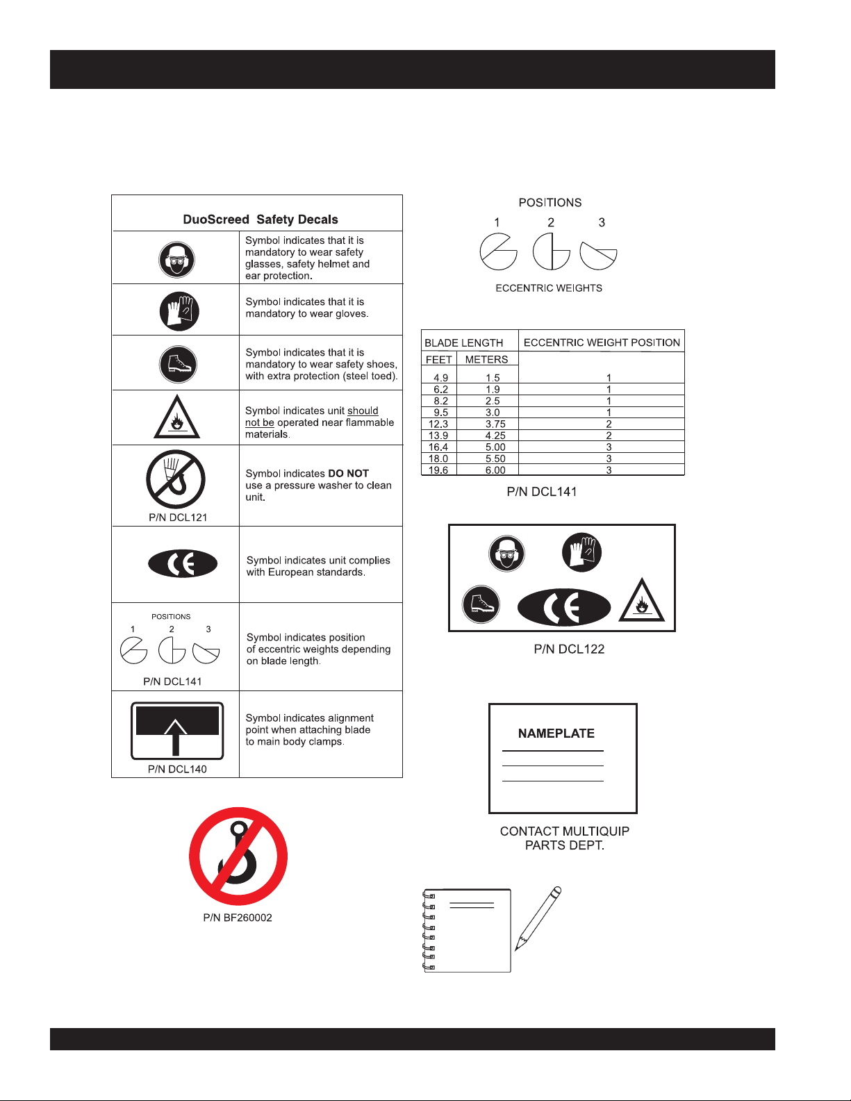
DSGPULW DUOSCREED — OPERATION AND SAFETY DECALS
Machine Safety Decals
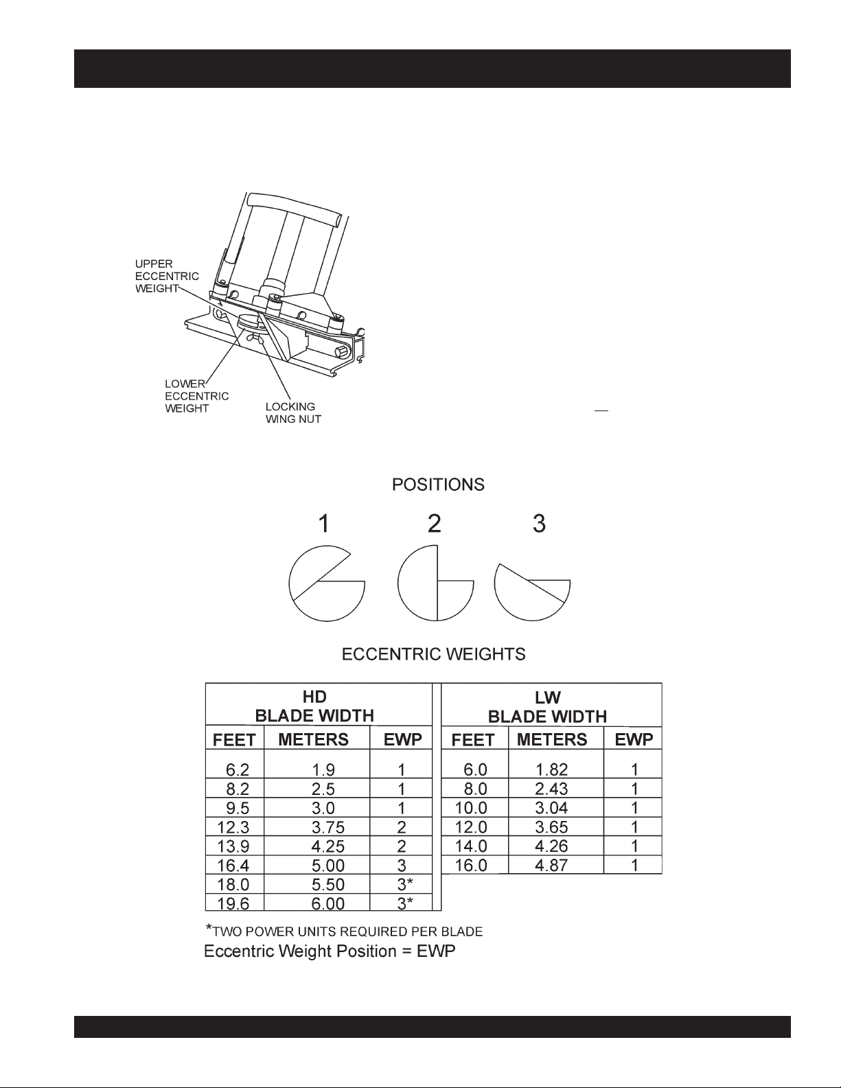
The DUOSCREED is equipped with a number of safety decals. These decals (Figure 1) are provided for operator safety and
maintenance information. The illustrations below shows these decals as they appear on the machine. Should any of these decals
become unreadable, replacements can be obtained from your dealer.
l
NOTE
Figure 1. Operation and Safety Decals
PAGE 10 — DSGPULW DUOSCREED — OPERATION AND PARTS MANUAL — REV. #6 (12/10/10)
ALL LW blades will use eccentric
position number 1
is for HD blades.
. Decal DCL 141
Page 11

DSGPULW DUOSCREED — SPECIFICATIONS
ledoMtinUrewoPWLUPGSD
snoitarbiVforebmuNnim/v005,5
metsySevirDtfahSelbixelF
riAnepO(esioN)A(Bd05
)
SNOITACIFICEPSDEERCSOUD.1ELBAT
noitareleccAnoitarbiVces/m5.1
)WL(thgieWtinUevirD).gK31(.sbl92
noitcurtsnoCedalByollAmunimulAdedurtxE
DHshtdiWedalB
WLshtdiWedalB
DHsthgieWedalB)m/gk2.4(.tf/.bl8.2.xorppA
WLsthgieWedalB)m/gk9.2(.tf/.b
ekaMenignEADNOH
ledoMenignETAS53XG
2
4.61,03.21,48.9,2.8,32.6
.tf86.91*dna40.81*,0
)sretem6*dna5.5*,0.5,57.3,0.3,5.2,9.1(
.tf61dna41,21,01,8,6
m78.4dna,62.4,56.3,40.3,34.2,28.1(
)srete
l59.1.xorppA
.stinurewopowteriuqerlliwshtdiwedalb)retem0.6dna5.5(.tf02dna81*
SNOITACIFICEPSENIGNE.2ELBAT
epyTenignEenignEenilosaGCHOekortS-4
fOrebmuN1
tnemecalpsiDmc8.53(ni.uc81.2
edarGliO03-W01EAS
yticapaCliO)retil01.0(/.tq11.0
epyTleuFdedaelnU
uF)sretil56.(/.lag271.
)yrD(thgieW)gk33.3(.sbl43.7
DSGPULW DUOSCREED — OPERATION AND PARTS MANUAL — REV. # 6 (12/10/10) — PAGE 11
srednilyC
tuptuOmumixaMmpr000,7/PH6.1
yticapaCknaTle
paGgulPkrapS
epyTgulPkrapS)KGN(H5RMC
dohteMgnitratStratS
lioceR
3
)
hcni820.0-420.0
)mm07.0-06.0(
Page 12

DSGPULW DUOSCREED — GENERAL INFORMATION
Introduction
The Multiquip DuoScreed is a hand held vibratory screed
designed to strike-off and consolidate concrete slabs. It is
comprised of two major components, the power unit (gasoline
engine), and the strike-off blade. Generally this screed
operates ideally in concrete with a slump of 2 inches or
greater. Its applications include patios, driveways, sidewalks
and floor slabs.
Assembly
There are no tools required to assemble the DuoScreed. The
power unit (engine) is connected to the to the blade by means of
a spring-loaded clamp. Springs within the clamp assembly
prevent vibration from loosening the power unit from the blade.
Handle Adjustments
The handle assembly on the DuoScreed is height adjustable for
operator comfort. The handle design used on this screed allows
the operator to remain upright at all times and can be quickly
adjusted without any tools.
Vibratory System
The vibratory system of the DuoScreed produces low amplitude
high frequency vibrations, designed to level and compact
concrete. This vibratory system is mounted at an angle to transmit
vibration laterally and vertically through the blade to produce a
strong, dense slab.
The engine drives a two piece eccentric weight by means of a
one-piece flexible shaft. This weight produces a vibratory action
which simultaneously allows the DuoScreed to level the slab
and consolidate the concrete beneath the surface.
Blades
The DuoScreed can utilize various blade widths. The type of
blades are defined as
The widths can range anywhere from 6~20 feet (1.82~ 6.00
meters). See Table 1 for more detailed information. Since different
length blades will require varying amounts of vibration, the
DuoScreed features adjustable eccentric weights. It is also
recommended that two power units be used if 18~20 foot (5.48~
6.0 meters) blades are required.
heavy duty
(HD) or
l
lightweight
(LW).
The blade of the DuoScreed offer a unique design with two
distinct edges and is manufactured from reinforced extruded
aluminum alloy. A curled edge is provided for applications that
allow the blade to ride on top of forms or rails. A smooth edge is
provided for wetscreed applications where the machine rides
entirely on concrete. Plastic end caps allow the blade to maneuver
around obstructions without marring the surface.
Engine
The Multiquip DuoScreed is equipped with a Honda Model
GX35SAT, 1.6 HP, mini 4-cycle gasoline engine. This engine is
lightweight and requires no fuel mixing.
Drive System
The Honda 1.6 HP engine drives a flexible shaft that requires no
greasing. Its short one piece design runs directly to the vibrator
housing and does not bend. This type of design eliminates a
major source of friction and reduces the likelihood of shaft failure.
Maneuverability
The HD blades have
referenced in Table 1. End caps are provided on each side of the
DuoScreed's blades to allow the screed to be easily maneuvered
around pipes or obstructions. End caps are not used on the LW
blades.
Transport
To transport your DuoScreed simply unclamp the power unit
from its base. Additionally, the handles can be folded down
for storage. The power unit weighs approximately 29 lbs.
(13.0 kg), while the HD blades weigh approximately 2.8 lbs/
ft. (4.2 kg/m) and the LW blades weigh 1.95 lbs/ft (2.9 kg/m)
Figure 2 shows the location of the components of the
DuoScreed. The function of each component is described
on the next page.
end caps
and are available in the lenghts
NOTE
Some blade widths may not be
available. Please contact MQ unit sales
for available blades.
PAGE 12 — DSGPULW DUOSCREED — OPERATION AND PARTS MANUAL — REV. #6 (12/10/10)
Page 13
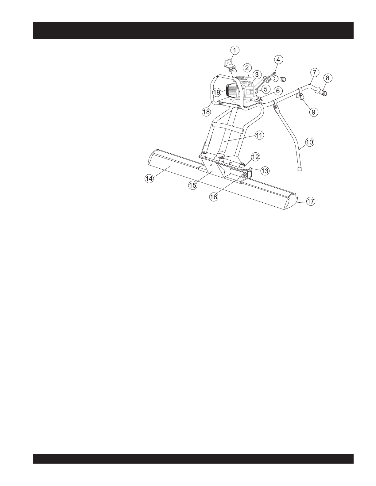
Figure 2. DuoScreed Components
DSGPULW DUOSCREED — COMPONENTS
Figure 1 shows the location of the components of the DuoScreed.
The function of each component is described below:
1. START/STOP Switch – When starting the engine, place
this switch in the START position. When stopping the
engine, place in the STOP position.
2. Recoil Starter – Manual-starting method. Pull the starter
grip until resistance is felt, then pull briskly and smoothly.
3. Oil Cap – Remove this cap to add engine oil.
4. Throttle Control Lever – Move the throttle lever to the
down
position for full throttle (max RPM's), for engine idle,
up
move the throttle lever to the
5. Fuel Cap/ Tank – Remove the fuel tank cap to add unleaded
fuel ONLY! DO NOT mix fuel. DO NOT over fill. Tank
holds approximately .172 gallons (.65 liters).
6. Handle Bar Adjustment Knobs – Loosen these two
knobs to adjust the handle bar to a suitable working position.
7. Handle Bar – Used in the steering of DuoScreed.
8. Hand Grip – When operating the DuoScreed use this hand
grip to maneuver the machine.
9. Support Stand Latch – Use this latch to lock support
stand in place when DuoScreed is in operation.
10. Support Stand – Use this stand to support the DuoScreed
when not in use.
11. Flexible Drive Shaft– Connected to the drive shaft of the
engine, provides the vibrational force for the eccentric
weights.
position.
12. Shock Mounts – Used to absorb the vibration generated
by the DuoScreed. These shock mounts minimize the
transfer of vibration to the operator.
13. Spring-Loaded Wing Nuts– Turn these 3 spring loaded
wing nuts counterclockwise to release the blade from the
aluminum clamping strip, turn clockwise to secure the blade
to the clamping strip.
14. Blades – The DuoScreed can be equipped with 2 different
type blade styles HD and LW. See Table 1 for details.
15. Eccentric Cover – Encloses the adjustable eccentric
weights. Press the spring clip tab inward and slide the cover
upward to gain access to the eccentric weights.
16. Locking Nuts – These 3 locking nuts are used in
conjunction with the 3 spring loaded wing nuts which
secure the blade to the aluminum clamping strip. Important!
always cover the two outer nuts with the provided plastic
cap. This will prevent concrete and other debris from
entering the quick disconnect system.
17. End Caps – Allows the DuoScreed to be maneuvered
around pipe or obstructions. End caps are used with HD
blades
18. Lifting Bar– This bar is only for manual lifting on the jobsite.
Not to be used for manual lifting with a forklift or other lifting
device.
19. Gasoline Engine – This DuoScreed uses a HONDA
GX35SAT 1.6 HP gasoline engine. Refer to the
owners manual for engine information and related topics.
only.
HONDA
DSGPULW DUOSCREED — OPERATION AND PARTS MANUAL — REV. # 6 (12/10/10) — PAGE 13
Page 14
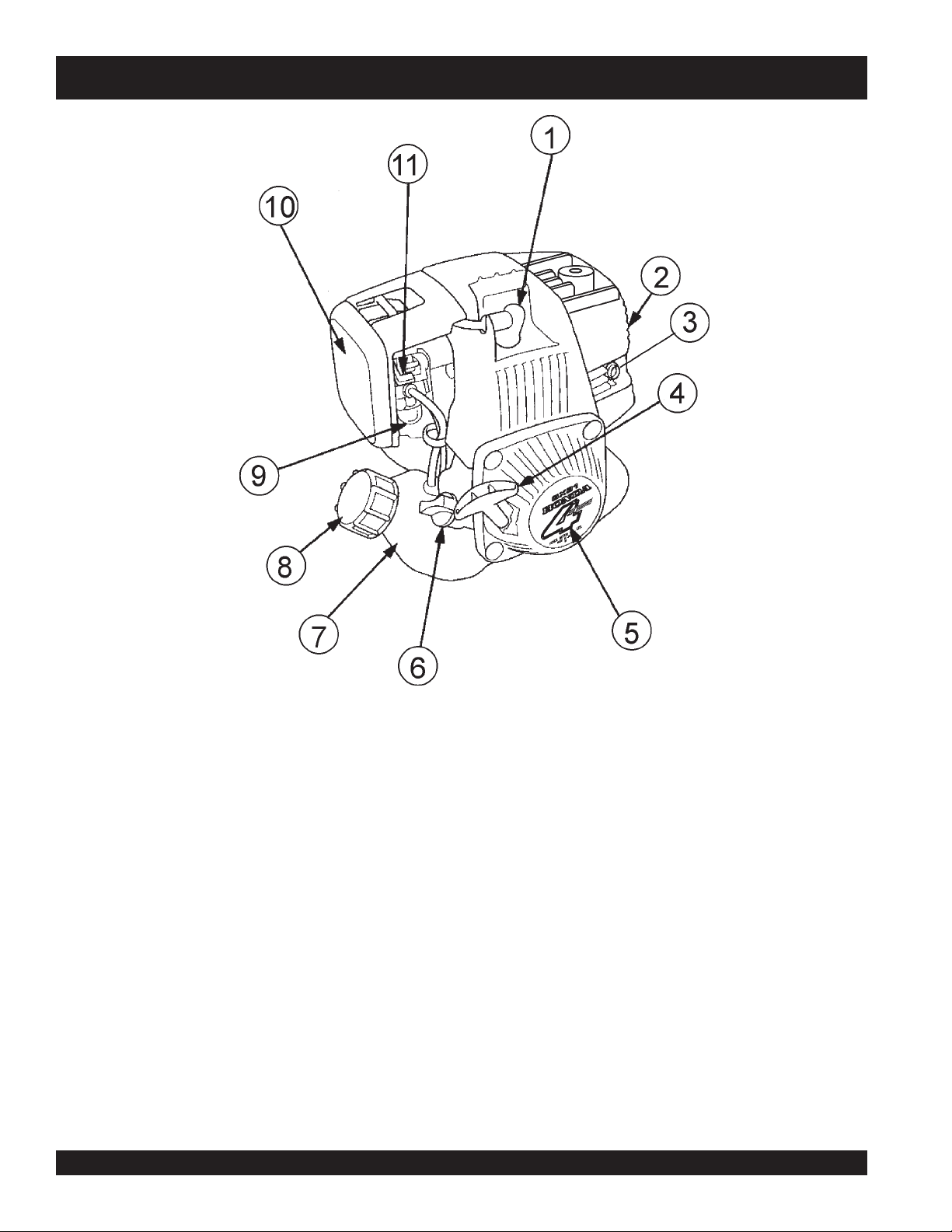
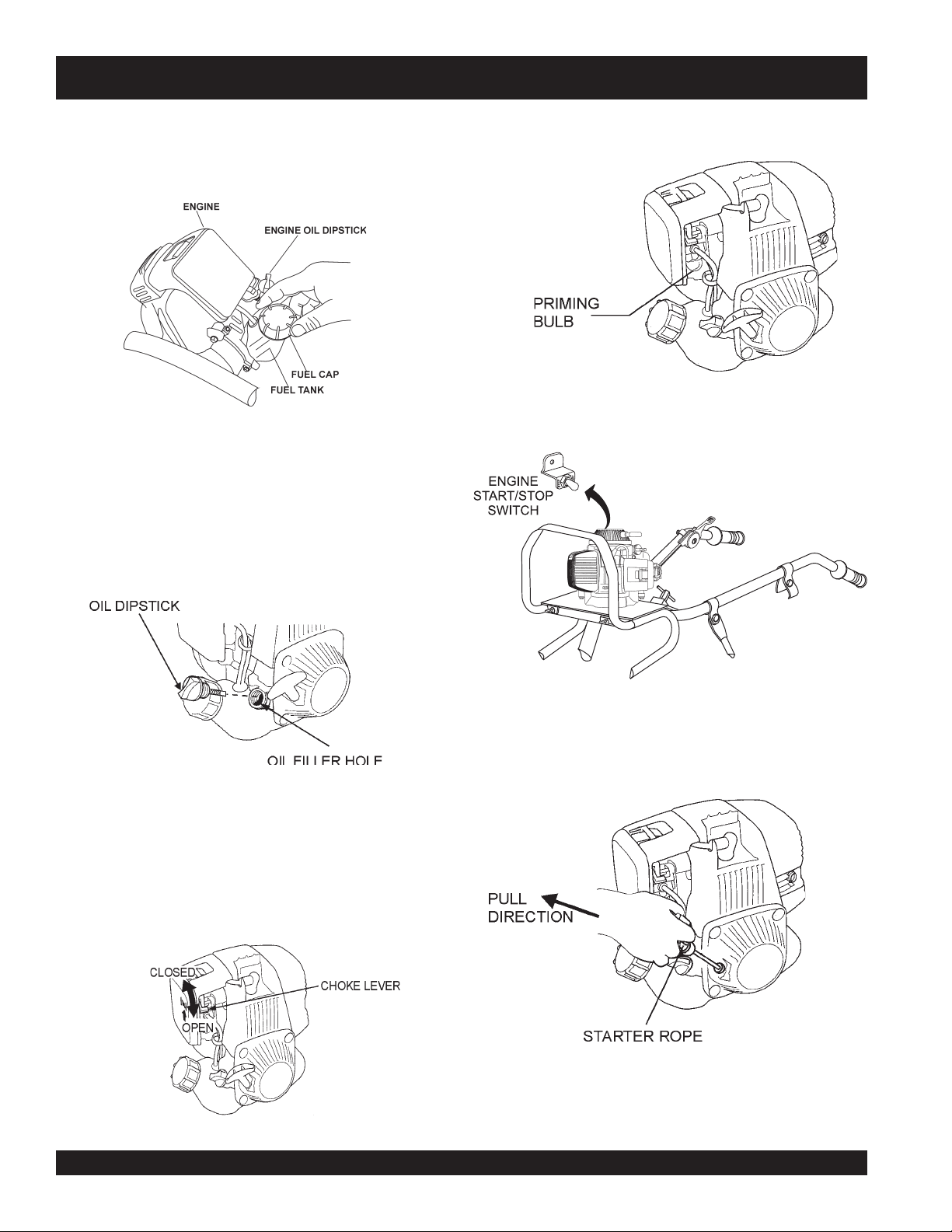
DSGPULW DUOSCREED — COMPONENTS (HONDA GX35SAT ENGINE)
Figure 2. HONDA GX35SAT Components
1. Spark Plug – Provides spark to the ignition system. Set
spark plug gap to 0.6 - 0.7 mm (0.024 - 0.028 inch) Clean
spark plug once a week.
2. Muffler – Used to reduce noise and emissions. DO NOT
touch muffler while engine is running, let engine cool before
performing any maintenance.
3. Spark Arrester – Prevents sparks from leaving the engine
exhaust system, which could ignite flammable materials.
4. Starter Grip – Grip this handle to start engine. See engine
starting section of this manual.
5. Recoil Starter (pull rope) – Type of engine starting method.
6. Oil Filler Cap – Remove this cap to add engine oil. Engine
oil capacity is 0.11 quart (0.1 liters). Use SAE 10W-30.
l
7. Fuel Tank – Holds .65 liters (approximately .172 gallon) of
8. Fuel Filler Cap – Remove this cap to add unleaded
9. Priming Bulb – Used in the starting of a cold engine or an
10. Air Cleaner – Prevents dirt and other debris from entering
11. Choke Lever – Used in the starting of a cold engine, or in
unleaded gasoline.
gasoline to the fuel tank. Make sure cap is tighten securely.
DO NOT over fill.
engine that has run out of fuel. Press the priming bulb
repeatedly until fuel can be seen inside the clear plastic
bulb.
the fuel system. Release latch on side of air filter
compartment to gain access to filter element.
cold weather conditions. The choke enriches the fuel mixture
for starting a cold engine.
PAGE 14 — DSGPULW DUOSCREED — OPERATION AND PARTS MANUAL — REV. #6 (12/10/10)
Page 15
DSGPULW DUOSCREED — ASSEMBLY INSTRUCTIONS
Assembly Instructions
This section will explain how to assemble the DuoScreed.
It is recommended that you familiarize
yourself with the DuoScreed’s
NOTE
1. The DuoScreed is comprised of two major components.
The power unit (Honda GX35SAT Engine) and the strikeoff blade. This DuoScreed is equipped with a quick
disconnect system, with which the power unit can be
mounted onto two aluminum clamping strips with ease.
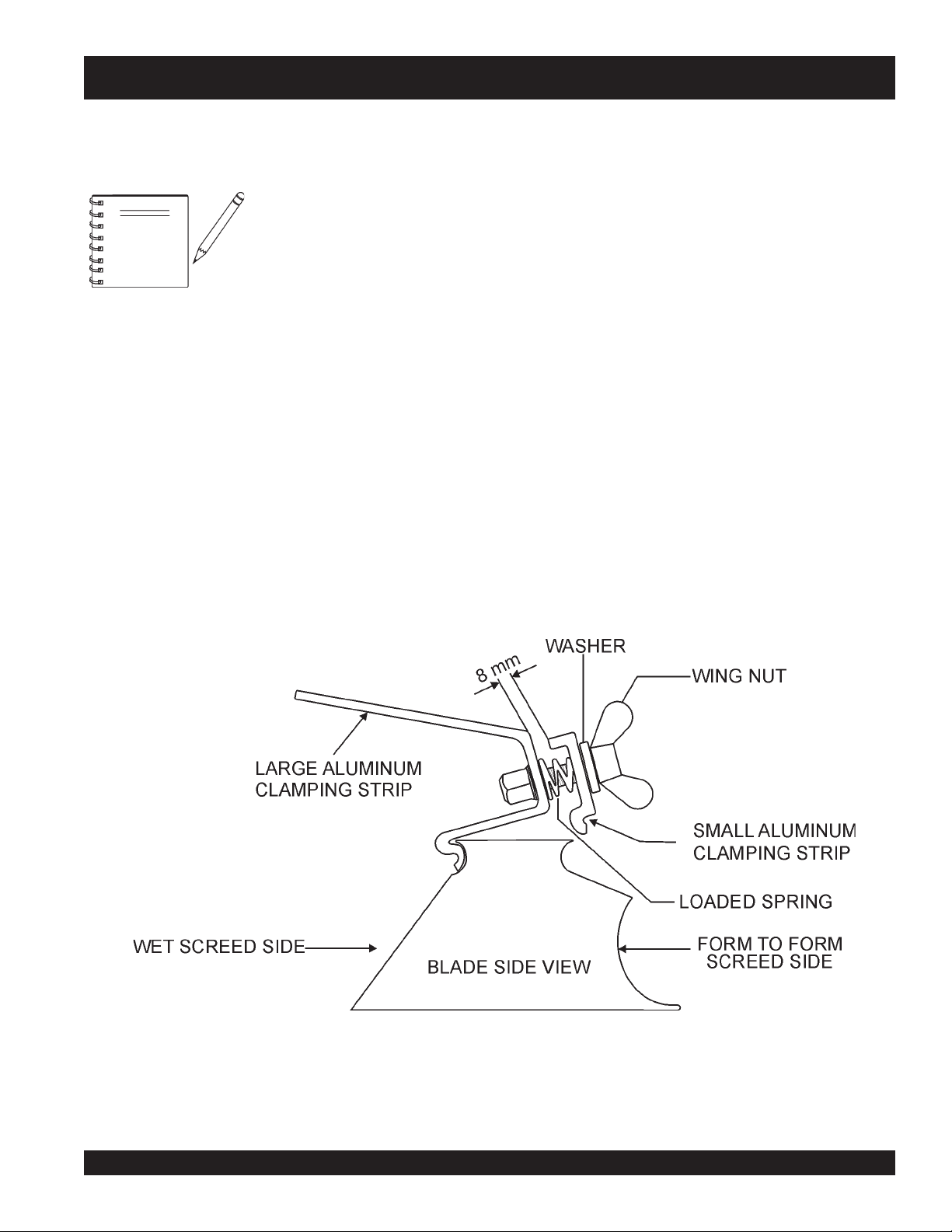
2. The aluminum clamping strip (retaining plate) is located at
the base of the power unit. This clamping strip is what
holds the blade in place with the aid of three quick
disconnect spring loaded wing nuts (Figure 3) that can
either be tighten or loosened by hand.
components. For assistance
identifying components called out in
the text, refer to Figure 1.
3. Determine whether you will be using the DuoScreed on
forms
unit will be mounted
screed the wing nuts should be located above the smooth
edge of the blade. If the DuoScreed will be used on forms
(Figure 3) the wing nuts should be located above the curled
edge of the blade.
4. Loosen each of the three wing nuts about 1/4 inch (8 mm).
It is not necessary to completely remove the wing nuts from
the aluminum clamping strip.
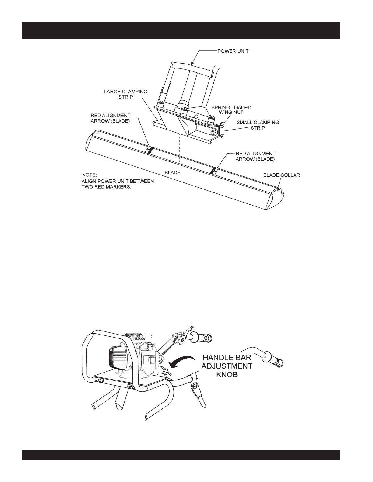
5. Locate the two red indicator arrows (Figure 4) on the top of
the blade. The power unit should be placed squarely
between the two markers.
or as a
wet screed
. This will decide how the power
.
If the DuoScreed will be used as a wet
Figure 3. Blade Quick Disconnect System
DSGPULW DUOSCREED — OPERATION AND PARTS MANUAL — REV. # 6 (12/10/10) — PAGE 15
Page 16
DSGPULW DUOSCREED — ASSEMBLY INSTRUCTIONS
Figure 4. Blade Mounting Diagram
6. Place the front of the power unit over the blade (Figure 3)
until the front of the clamp is seated within the front blade
collar.
7. Ease the power unit back to allow the rear clamp to seat
itself within the rear blade collar. It may be necessary to
further loosen the wing nuts to allow the clamp to fit around
the blade collar.
8. Securely hand tighten each of the three wing nuts. The
wing nuts are spring loaded to prevent them from coming
loose during operation.
l
9. Two handle bar adjustment knobs (Figure 5) are located at
the base of the steering handle bar. Loosen these two knobs
to adjust the height of the steering handle bar to a suitable
working position.
10. The DuoScreed is now ready for operational use.
Figure 5. Handle Bar Adjustment Knob
PAGE 16 — DSGPULW DUOSCREED — OPERATION AND PARTS MANUAL — REV. #6 (12/10/10)
Page 17
DSGPULW DUOSCREED — ASSEMBLY INSTRUCTIONS
Eccentric Weight Adjustment
There are two eccentric weights (Figure 6) that are supplied
with the DuoScreed. These weights are located inside the
eccentric weight compartment, which is located at the bottom of
the unit.
Figure 6. Eccentric Weight Location
These weights determine the amount of vibration that will travel
down the blade. Depending on the type of blade that is used, will
determine the position of the two eccentric weights. Reference
Figure 7 in determining how your eccentric weights should be
positioned.
1. To gain access to the eccentric weight compartment, press
the spring clip tab on the eccentric cover and slide the
cover upward to remove.
2. Loosen the eccentric locking wing nut.
3. Use the chart in Figure 7 to determine what position your
eccentric weights should be in (position 1, 2 or 3).
Example:
A 16 ft. (5.0 meters) blade will place the eccentric weights in
position 3. Please note that
all LW blades widths use position 1.
Figure 7. Eccentric Weight Positions
DSGPULW DUOSCREED — OPERATION AND PARTS MANUAL — REV. # 6 (12/10/10) — PAGE 17
Page 18
DSGPULW DUOSCREED — STARTING
Engine Pre-Check
1. Fill the fuel tank (Figure 8 ) with unleaded gasoline. DO NOT
over fill. Topping-off to filler port is dangerous, as it tends to
spill fuel. Wipe up any spilled fuel immediately.
Figure 8. Fuel Tank
1. Place the engine in a level position.
2. Check the engine oil level by unscrewing the engine oil dip
stick (Figure 9) from its holder.
3. If oil is not observed at the edge of the oil filler hole, fill with
oil until oil is present at edge of oil filler hole. Remember to
add oil slowly to avoid overflowing, as the engine oil tank
capacity is small.
2. Press the priming bulb (Figure 11) repeatedly until fuel can
be seen inside the clear plastic bulb.
3. Set the engine START/STOP switch (Figure 12) to the
START position.
Figure 11. Priming Bulb Location
Figure 9. Engine Oil Dipstick/Oil Filler Hole
4. Reinstall the engine oil dipstick securely.
Starting The Engine
1. To start a cold engine, move the choke lever (Figure 10) to
the CLOSED position. If restarting a warm engine leave the
choke lever in the OPEN position.
Figure 10. Choke Lever
l
Figure 12. Engine START/STOP Switch
4. Pull the starter rope (Figure 13) lightly until you feel resistance, the pull briskly. Return the starter rope gently.
Figure 13. Engine Starter Rope
5. Once the engine has started, allow it to idle for 3 to 5 minutes.
PAGE 18 — DSGPULW DUOSCREED — OPERATION AND PARTS MANUAL — REV. #6 (12/10/10)
Page 19
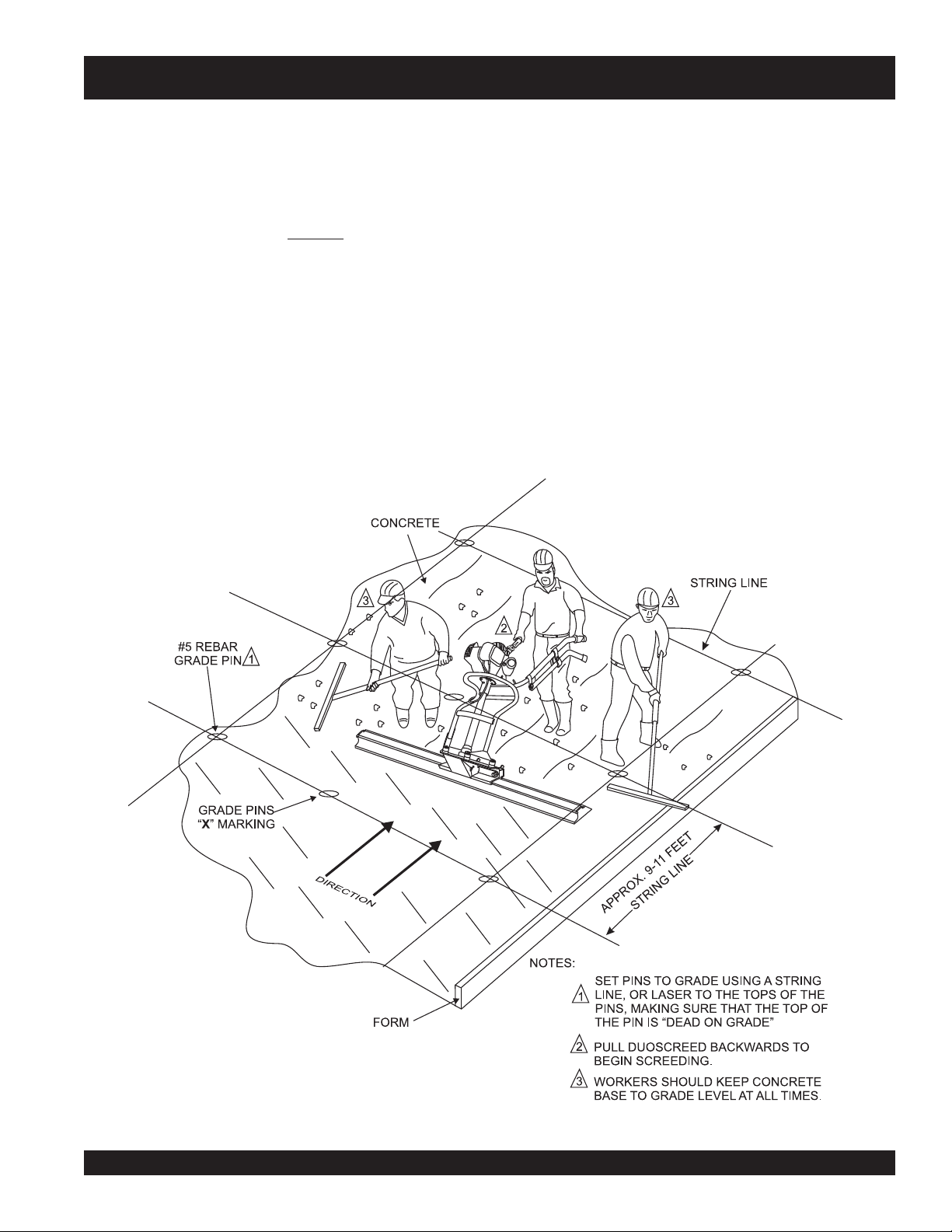
Application/Operation
DSGPULW DUOSCREED — APPLICATION/OPERATION
1. Before placing the DuoScreed in concrete for screeding,
it is a good idea to apply
frame parts that may come in contact with the concrete.
This form oil will become useful when cleaning the
DuoScreed. Make sure to
amount of form oil.
2. Prepare a grid of #5 rebar pins (Figure 14) equally spaced
approximately every 9 to 11 feet. If a 10 ft. screed blade
is going to be used space the grade pins every 9 feet, if
a 12 ft. screed blade is required, space the grade pins
every 11 ft. Make sure to drive the pins deeply into the
ground.
3. Use a
string line
The grade should be to the top of the grade pins. Remember, before any concrete is to be poured, make sure that
the top of the pins are dead on grade.
or
form oil
saturate the unit with a good
laser
to set the pins to grade (height).
to the blade and all
4. Once all the grade pins have been placed correctly and
are dead on grade, concrete can then be poured on top
of grade pins.
5. Level, and form the concrete as close as possible to
grade. Mark the top of each pin so that its exact location
will be known. Use a hand trowel to float the edges and
plumbing grade pins.
6. If chalk lines are used for grade against forms, walls or
existing concrete, float out the grade with a hand float
along the edge.
7. Two workers will be required to assist the DuoScreed
operator when making the 12-18 concrete bases, one on
each side. These workers will rake the concrete in toward
the center of the DuoScreed away form the bases to avoid
changing base elevation.
Figure 14. DuoScreed On Forms and Grade Pins
DSGPULW DUOSCREED — OPERATION AND PARTS MANUAL — REV. # 6 (12/10/10) — PAGE 19
Page 20
DSGPULW DUOSCREED — APPLICATION/OPERATION
13. Repeat steps 9 through 12 pulling the DuoScreed from
the edge of the grid's
the center.
14. Remember to build the bases in long parallel strips
across the pins and on the hand floated edges and
against plumbing or other outs, leaving the long unfinished areas about 8 or 9 feet wide. Once the bases are
built, the workers can more accurately shape the concrete
to grade.
15. When
his two workers can begin to work down the long parallel
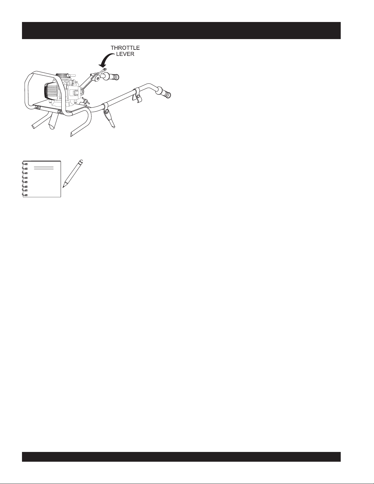
Figure 15. Throttle Lever
Before placing the DuoScreed in
concrete, make certain the unit has
NOTE
8. Set the DuoScreed blade down in the concrete base in the
left
most corner of the grid between the two grade pins as
shown in Figure 16. Adjust the DuoScreed's handle bar
to a height where the operators is not bending over, but
standing upright with arms extended forward.
9. To begin screeding move the engine throttle lever (Figure
15) midway between idle and full throttle. Notice that the
DuoScreed's vibration will cause the blade to sink into the
concrete base until it touches the top of the grade pins
10. Pull the DuoScreed from the edge of the grid's
corner, horizontally toward the
DuoScreed passes over the grade pins a small circle of
concrete around the grade pins will appear. This indicates
that the Duoscreed has vibrated the grade pin, and that
the operators is
11. Keep the DuoScreed blade level and create a level base
between 12-18 inches wide.
been set up (blade) for
This can be verified by observing that
the operator's toes are pointing
towards the smooth side of the blade
(Figure 3), from the operators's position
(handle bars).
l
center
dead on grade
.
wet screeding
.
top left
. Notice that as the
unfinished 8 to 9 foot wide middle portions. When moving the
DuoScreed down the middle portions, the ends of the
DuoScreed blade should be resting on the bases, and the
leading edge of the blade should be approximately 1/8 to
1/4 inch above each base depending on the slump and
condition of the concrete. Have workers adjust the concrete
along the face of the DuoScreed's blade to assure that the
base is level with no high or low areas ahead of the blade.
16. Keep the engine throttle between 1/2 to 2/3 of full speed, if
necessary readjust the DuoScreed's vibration to meet the
condition of the concrete. Remember to move rapidly and
watch both ends of the blade to assure that the blade remains
1/8 to 1/4 of an inch above the concrete base. Always keep
the workers alert for concrete height changes.
Shut-Down
1. NEVER
speed.
2. Move the engine
speed position (idle).
3. Set the engine ON/OFF switch (Figure 12) to the OFF
position.
4. Remove the DuoScreed from the slab surface.
Cleaning
1. Allow the engine to
has cooled, use a damp and a mild detergent to remove all
concrete and foreign debris. DO NOT spay the engine with
water.
top right
all
the bases have been completed, the operator and
stop
the engine suddenly while running at high
throttle lever
cool
corner, horizontally toward
(Figure 15) to the low
before cleaning. When the engine
12. After a complete pass over the first set of grade pins has
been made, remove the DuoScreed from the concrete
base and position it over the second set of grade pins
(Figure 16), overlapping the first set of grade pins be-
left
tween 12-18 inches. Repeat this process until all
grade pins have a level base between 12-18 inches wide.
PAGE 20 — DSGPULW DUOSCREED — OPERATION AND PARTS MANUAL — REV. #6 (12/10/10)
edge
2. To remove all concrete and foreign debris from the
DuoScreed, wash the DuoScreed's blade and frame using
water and a mild detergent. Remember, if form oil was
applied before the machine was placed in concrete, the
cleanup will be much easier.
Page 21

DSGPULW DUOSCREED — APPLICATION/OPERATION
TOP LEFT
CORNER OF
GRID
STEP 1
PLACE # 5 REBAR GRADE PINS
AND FORM RECTANGULAR GRID.
BLADE OVERLAP
12-18 INCHES
STEP 2
POUR CONCRETE
AND FORM TO GRADE
12-18 INCH
BASE
HORIZONTAL
DIRECTION
DUOSCREED BLADE
HORIZONTAL
DIRECTION
HORIZONTAL
DIRECTION
HORIZONTAL
DUOSCREED BLADE
DIRECTION
STEP 7
DUOSCREED BLADE
VERTICAL
DIRECTION
STEP 7
SET SCREED BLADE DOWN ON
UNFINISHED 8 TO 9 FT. WIDE
MIDDLE SECTION, PLACING
BOTH ENDS OF THE BLADE
ON THE 12-18 INCH BASES.
STEP 7
12-18 INCH
BASE
HORIZONTAL
DIRECTION
HORIZONTAL
DIRECTION
HORIZONTAL
DIRECTION
HORIZONTAL
DIRECTION
DUOSCREED BLADE
BLADE OVERLAP
12-18 INCHES
DUOSCREED BLADE
TOP RIGHT
CORNER OF
GRID
STEP 3
MAKE 12-18 INCH
BASE (LEFT SIDE)
STARTING IN THE TOP LEFT CORNER OF GRID,
BUILD 18 INCH WIDE PARALLEL CONCRETE BASES
ACROSS GRADE PINS FROM TOP TO BOTTOM OF GRID.
STEP 4
APPROX.
8-9 FT.
RECTANGULAR
GRID
STARTING IN THE TOP RIGHT CORNER OF GRID,
BUILD 18 INCH WIDE PARALLEL CONCRETE BASES
ACROSS GRADE PINS FROM TOP TO BOTTOM OF GRID.
STEP 6
Figure 16. DuoScreed Wet Screeding Application
STEP 5
MAKE 12-18 INCH
BASE (RIGHT SIDE)
DSGPULW DUOSCREED — OPERATION AND PARTS MANUAL — REV. # 6 (12/10/10) — PAGE 21
Page 22

DSGPULW DUOSCREED — APPLICATION/OPERATION
Important Tips to Remember
■
Do not allow the engine to run out of fuel as this may cause
problems with starting. Always maintain an extra supply of
fuel on the job site.
■
Always keep the DuoScreed moving backwards during
operation. Allowing the DuoScreed to vibrate in the same
location for too long will cause it to sink into the concrete.
■
When using the DuoScreed with low slump (dry) concrete do
not attempt to walk it quickly across the slab. Walk slowly to
allow the vibratory action to consolidate and level the slab
surface. When using the DuoScreed with high slump (wet)
concrete you will be able to walk the machine across the slab
at a faster pace.
■
In applications where the Duoscreed is being used as a wet
screed it is recommended that grade or height of the concrete
slab be adjusted with a laser device.
■
Proper vibratory force is essential to producing a
durable
eccentric weights
troubleshooting section of this manual.
■
When screeding using forms or rails, always size your screed
blade appropriately for the job. It is best to have the blade
extend beyond the forms, by about 6-inches on each side.
slab. If the DuoScreed is vibrating too strongly the
will require adjustment. Refer to the
level, hard
■
■
■
■
■
■
■
,
When screeding make sure the blade is kept straight. DO
NOT let blade turn.
DO NOT run the DuoScreed with one part of the blade on
forms and the other on base. The blade must either be placed
on forms or float (wet screeding), but not a combination of the
two techniques.
DO NOT stand in the concrete with the engine throttle
engaged. This will cause the DuoScreed to sink.
If the concrete appears too wavy, you are moving too slowly,
increase your backing-up speed.
Always keep the workers back far enough too allow the
operator to see the cutting face of the blade as it rides on the
wet screed base.
The operator should keep the screed blade about 1/8 to 1/4
inch above the concrete base at all times.
Should the DuoScreed stick to the wet concrete slab, DO
NOT attempt to lift it. Quickly increase engine rpm's while
pushing forward on the handles to free the machine.
l
PAGE 22 — DSGPULW DUOSCREED — OPERATION AND PARTS MANUAL — REV. #6 (12/10/10)
Page 23

DSGPULW DUOSCREED — MAINTENANCE
Maintenance
3. Use a low pressure water hose, soft brush, wiping cloth
CAUTION - Pressure Washer
DO NOT clean the DuoScreed with a
pressure washer
.
4. Keep the drive unit free from grease, dirt and grime as this
30 - Day Storage Procedure
1. NEVER clean the DuoScreed with the engine running.
2. Allow the engine to cool down before cleaning.
For storage of the DuoScreed for over 30 days, the following is
required:
NOTE
DO NOT allow concrete to
on the DuoScreed. Wipe all
harden
concrete off the chrome frame and
any other parts including the
engine of the DuoScreed.
TSRIF
)3(NOITPIRCSEDNOITAREPOEROFEB
HTNOM
RO
.SRH01
and a mild cleaning detergent and remove all concrete
from the DuoScreed. Be careful not to get excessive amounts
of water in the engine compartment.
can effect the performance of your DuoScreed
Drain the fuel tank completely.
Run the engine until the fuel in the injection system is
completely consumed.
Completely drain used oil from the engine crankcase and
fill with fresh clean oil, then follow the procedures described
in the engine manual for engine storage.
Cover DuoScreed and engine with plastic covering or
equivalent and store in a clean, dry place.
eludehcSecnanetniaMenignE.3elbaT
YREVE
SHTNOM3
RO
.SRH52
YREVE
SHTNOM6
RO
.SRH05
YREVE
RAEY
RO
01
.SRH0
YREVE
SRAEY2
RO
.SRH002
liOenignE
renaelCriA
stloB&stuNllA
gulPkrapS
sniFgnilooCKCEHCX
retserrAkrapSNAELC X
knaTleuFNAELC X
retliFleuFKCEHC X
seohShctulCKC
deepSeldITSUJDA-KCEHC )2(X
ecnaraelCevlaVTSUJDA-KCEHC )2(X
senilleuFKCEHC )2()yrassecenfiecalper(sraey2
KCEHCX
EGNAHCXX
KCEHCX
EGNAHC)1(X
fInethgit-eR
yrasseceN
NAELC-KCEHCX
ECALPER X
EHC)2(X
X
nidesunehwyltneuqerferomecivreS)1( YTSUD .saera
yrevE
dcivresruoyybdecivresebdluohssmetiesehT)2(
serudecorpecivresroflaunaMpohsADNOHehtotrefeR.tneiciforp
yllacinahcemeradnaslootreporpehtevahuoysselnu,relae
avretniecnanetniamreporpenimretedotnoitarepofosruohgol,esulaicremmocroF)3(
.sl
DSGPULW DUOSCREED — OPERATION AND PARTS MANUAL — REV. # 6 (12/10/10) — PAGE 23
Page 24

DSGPULW DUOSCREED — MAINTENANCE
Air Cleaner
1. The air cleaner element should be cleaned because a
clogged air cleaner can cause poor engine starting, lack of
power and shorten engine life substantially.
2. Before opening the air cleaner compartment, wipe any dirt
or foreign matter from the air cleaner body and cover, using
a moist cloth. Be careful to prevent dirt from entering the
carburetor
3. Press the latch tab on the top of the air cleaner cover (Figure
16), and remove the cover. Check the filter to be sure that it
is clean and in good condition.
3. Remove the spark plug with 5/8-inch wrench.
4. Inspect the spark plug. Replace it if the electrodes are worn,
or if the insulator is cracked or chipped. Clean the spark
plug with a wire brush if you are going to reuse it.
5. Set the spark plug gap (Figure 18) using a suitable gauge.
The gap should be between 0.024-0.028 inch (0.60-0.70
mm).
6. Carefully install the spark plug by hand to avoid cross
threading, the tighten
Figure 18. Spark Plug Gap
7. Attach spark plug cap.
Figure 16. Air Cleaner
Spark Plug
1. Make sure the engine is off and cool.
2. Disconnect the spark plug cap ( Figure 17), and remove
any dirt from around the spark plug area.
l
Figure 17. Spark Plug Removal
PAGE 24 — DSGPULW DUOSCREED — OPERATION AND PARTS MANUAL — REV. #6 (12/10/10)
Page 25

DSGPULW DUOSCREED — TROUBLESHOOTING
GNITOOHSELBUORTDEERCSOUD.4ELBAT
MOTPMYSESUACELBISSOPNOITULOS
tessirotarbivehtfoecroflagufirtnecehT
?woloot
ehttluserasadnatneiciffusnisetarbiV
dnadelevelebtonnacroolfetercnoc
pehtnidehtooms
.
stroppus
.gnideercs
.yawrepor
?egral
-mrofasadesunehwdeercSouDehT
dnahcumootsetarbivdeercsmrof-ot
liarehtssorcaylhtoomslevarttonseod
deercsehtsa"YVAW"skooletercnoC
.tirevosessapedalb
tewg
nirudstopsWOLroHGIHgnivaeL
?hctamton
?ylwolsootgnivomrotarepO
?etercnoc
etercnocfostnuomaevissecxesierehT
?edalbehtfoegdegnidaelehtgnola
ootsiedalbehtfohtdiwnesohcehT
odsthgiewcirtneccednaedalbdetceleS
foepytehtrofnoitarbivhcumooT
?edisenonowolrohgihootetercnoC
rugiFrep
.deeps
eR
.edalbehtmorf
2(.tf02
.ecap
)senigne
erugiFecnerefeR
kcabklaW
cetercnoc
sthgiewcirtnecceehttsujdA
enigneesaercniro7e
etercnocevissecxeehtevom
edalbrellamsahtiwkroW
sihtdiwmumixamrebmemeR
otsthgiewcirtneccetsujdA
.htdiwedalbdetceleshctam
.7
retsafatasdraw
klawdnadeepsenigneecudeR
.ecapretsafatasdrawkcab
ehtepahssrekrowevaH
otelbissopsaesol
fohcni1tuobaniatniaM.edarg
fotnorfehtssorccaetercnoc
.semitllataedalbeht
alB?yltcerrocdenoitisopedalbsI
.etercnoctewotnisgided
tsumedalbehtfodnehcaE
.ecafrusemasehtnoedir
edalbehtfodnehcaerehtiE
rcnocrosmrofnosedir
.htobton)deercs
tew(ete
DSGPULW DUOSCREED — OPERATION AND PARTS MANUAL — REV. # 6 (12/10/10) — PAGE 25
Page 26

DSGPULW DUOSCREED — TROUBLESHOOTING
GNITOOHSELBUORTENIGNE.5ELBAT
MOTPMYSESUACELBISSOPNOITULOS
?gnigdirbgulpkrapS
ontub,elbaliavasileuf",tratsottluciffiD
."gulpkrapstaKRAPS
?noitalusni
?evitcefedliocnoitingI.liocnoitingiecalpeR
dna,elbaliavasileuf",tratsottluciffiD
."gulpkrapsehttatneserpsiKRAPS
?gnitiucric
?epytleufgnorW
?gulpkrapsnotisopednobraC .gulpkrapsecalperronaelC
ifedoteudtiucrictrohS
?paggulpkrapsreporpmI.pagreporp
?detrohssihctiwsFFO/NO
sronekorberiwgulpkrapS
gulpkrapstneic
?yrtridstniop,pagkrapsreporpmI
trohsronrownoitalusniresnednoC
?gnitiucrictroh
.nrowfiecalper
otteS
.hctiws
.stniopnaelc
.gniriw
ronoitalusni,pagkcehC
.gulpkrapsecalper
,noitalusnigulpkrapskcehC
ecalper
,gniriwhctiwskcehC
dnapa
gkrapstcerrocteS
.resnednocecalpeR
gulpkrapsevitcefedecalpeR
ecalperdna,metsysleufhsulF
.leuffoepyttcerrochtiw
kraps,elbaliavasileuf",tratsottluciffiD
inoisserpmocdnatneserpsi
l
ileuf",tratsottluciffiD
"lamrons
kraps,elbaliavas
"wolsinoisserpmocdnatneserpsi
.blubgnimirpedisnitneserpleufoN
udroretaW.metsysleufhsulF
?ytridrenaelcriA .renaelcriaecalperronaelC
?nepOekohC.ekohCesolC
nethgit
?degamad
?ylreporpde
?deggolcretlifleuF.retlifleufecalpeR
?enilleufniriA.
?metsysleufnits
?dedurtorprokcutsevlavtsuahxe/noitcuS.sevlavtaes-e
?nrowrednilycro/dnagnirnotsiP
tongulpkrapsro/dnadaehrednilyC
teksaggulpkrapsro/dnateksagdaeH
?knatleufnielbaliavatonleuF .leuffoepyttcerrochtiwlliF
?deggolcelohrehtaerbpacknatleuF .packnatleufecalperronaelC
R
rodnasgnirnotsipecalpeR
.notsip
dnastlobdaehrednilyceuqroT
.gulpkraps
lpeR
.steksag
enilleufdeelB
gulpkrapsdnadaeheca
PAGE 26 — DSGPULW DUOSCREED — OPERATION AND PARTS MANUAL — REV. #6 (12/10/10)
Page 27

DSGPULW DUOSCREED — NOTE PAGE
DSGPULW DUOSCREED — OPERATION AND PARTS MANUAL — REV. # 6 (12/10/10) — PAGE 27
Page 28

DUOSCREED — EXPLANATION OF CODE IN REMARKS COLUMN
The following section explains the different symbols and
remarks used in the Parts section of this manual. Use the
help numbers found on the back page of the manual if there
are any questions.
NOTICE
The contents and part numbers listed in the parts
section are subject to change without notice. Multiquip
does not guarantee the availability of the parts listed.
SAMPLE PARTS LIST
NO. PART NO. PART NAME QTY. REMARKS
1 12345 BOLT ......................1 .....INCLUDES ITEMS W/%
2% WASHER, 1/4 IN. ...........NOT SOLD SEPARATELY
2% 12347 WASHER, 3/8 IN. ...1 .....MQ-45T ONLY
3 12348 HOSE ..................A/R ...MAKE LOCALLY
4 12349 BEARING ..............1 .....S/N 2345B AND ABOVE
NO. Column
Unique Symbols — All items with same unique
symbol
QTY. Column
Numbers Used — Item quantity can be indicated by a
number, a blank entry, or A/R.
A/R (As Required) is generally used for hoses or other
parts that are sold in bulk and cut to length.
A blank entry generally indicates that the item is not sold
separately. Other entries will be clarified in the “Remarks”
Column.
REMARKS Column
Some of the most common notes found in the “Remarks”
Column are listed below. Other additional notes needed
to describe the item can also be shown.
Assembly/Kit — All items on the parts list with the
same unique symbol will be included when this item is
purchased.
Indicated by:
“INCLUDES ITEMS W/(unique symbol)”
(@, #, +, %, or >) in the number column belong to the
same assembly or kit, which is indicated by a note in the
“Remarks” column.
Duplicate Item Numbers — Duplicate numbers indicate
multiple part numbers, which are in effect for the same
general item, such as different size saw blade guards in
use or a part that has been updated on newer versions
of the same machine.
NOTICE
When ordering a part that has more than one item
number listed, check the remarks column for help in
determining the proper part to order.
l
PART NO. Column
Numbers Used — Part numbers can be indicated by a
number, a blank entry, or TBD.
TBD (To Be Determined) is generally used to show a
part that has not been assigned a formal part number
at the time of publication.
A blank entry generally indicates that the item is not sold
separately or is not sold by Multiquip. Other entries will
be clarified in the “Remarks” Column.
Serial Number Break — Used to list an effective serial
number range where a particular part is used.
Indicated by:
“S/N XXXXX AND BELOW”
“S/N XXXX AND ABOVE”
“S/N XXXX TO S/N XXX”
Specific Model Number Use — Indicates that the part
is used only with the specific model number or model
number variant listed. It can also be used to show a
part is NOT used on a specific model or model number
variant.
Indicated by:
“XXXXX ONLY”
“NOT USED ON XXXX”
“Make/Obtain Locally” — Indicates that the part can
be purchased at any hardware shop or made out of
available items. Examples include battery cables, shims,
and certain washers and nuts.
“Not Sold Separately” — Indicates that an item cannot
be purchased as a separate item and is either part of an
assembly/kit that can be purchased, or is not available
for sale through Multiquip.
PAGE 28 — DSGPULW DUOSCREED — OPERATION AND PARTS MANUAL — REV. #6 (12/10/10)
Page 29

DSGPULW DUOSCREED — SUGGESTED SPARE PARTS
DUOSCREED 1 TO 3 UNITS WITH HONDA
GX35SAT ENGINE
1 to 3 Units
Qty. ........ P/N .............................. Description
2 ............ BF2648 ....................... HANDLE GRIP
1 ............ BF2647 ....................... THROTTLE GRIP
2 ............ BF2645LW .................. THROTTLE CABLE
1 ............ BF2621LW .................. FLEXIBLE SHAFT
1 ............ BF2609N .................... ECCENTRIC COVER
3 ............ BF2607 ....................... COMPRESSION SPRING
1 ............ BF2605LW .................. ALUMINUM CLAMPING STRIP
3 ............ BF0176 ....................... WASHER
3 ............ BF2606 ....................... WING BOLT
1 ............ BF2643 ....................... STOP SWITCH
3 ............ BF0325 ....................... WING BOLT M6X12
3 ............ 31915Z0H003 ............. SPARK PLUG, NGK
3 ............ 17211Z0Z000 ............. ELEMENT AIR
1 ............ 15600ZM3003 ............. CAP, OIL FILLER
1 ............ 28400Z0Z003 ............. RECOIL STARTER ASSY.
3 ............ 17672ZM3003 ............. FILTER, FUEL
1 ............ 17620ZM3043 ............. CAP ASSY., FUEL TANK
1 ............ 28462ZM3003 ............. ROPE, RECOIL STARTER
NOTE
Part numbers on this Suggested Spare Parts List
may supercede/replace the
P/N shown in the text
pages of this book.
DSGPULW DUOSCREED — OPERATION AND PARTS MANUAL — REV. # 6 (12/10/10) — PAGE 29
Page 30

NAME PLATE AND DECALS.
DSGPULW DUOSCREED — NAME PLATE AND DECALS
l
PAGE 30 — DSGPULW DUOSCREED — OPERATION AND PARTS MANUAL — REV. #6 (12/10/10)
Page 31

DSGPULW DUOSCREED — NAME PLATE AND DECALS
NAME PLATE AND DECALS.
NO PART NO PART NAME QTY. REMARKS
1
*
2
*
3 PLATE, SERIAL NO. ......................... 1 ............ CONTACT MQ PARTS DEPT. W/MODEL & S/N
4
*
5
*
6 BF260002 DECAL, DO NOT LIFT (HOOK) 1
SEE DECAL ILLUSTRATIONS.
DCL121 DECAL, PRESSURE HOSE 1
DCL122 DECAL, SAFETY 1
DCL140 DECAL, ALIGNMENT ARROWS ..... 2
DCL141 DECAL, ECCENTRIC WT. CHART 1
DCLDS-SERIES KIT, DECAL ....................................... 1 ............ INCLUDES ITEMS W/
*
DSGPULW DUOSCREED — OPERATION AND PARTS MANUAL — REV. # 6 (12/10/10) — PAGE 31
Page 32

DUO SCREED MAIN ASSY.
OLD STYLE
CENTRIFUGAL
HOUSING
9
1
8
5
7
6
5A
1
86
NEW STYLE
CENTRIFUGAL
HOUSING
79
16
4
60
87
83
85
84
88
57
67
78
STOP
T
R
A
T
S
DSGPULW DUOSCREED — MAIN ASSY.
80
75
68
74
1
76
71
73
1
10
58
3
2
72
69
18
20
17
18
30
REFERENCE
ONLY
45
13
12
15
14
11
l
51
52
59
52
53
63
66
47
48
65
49
50
28
46
31
82
18
24
43
42
41
22
37
32
19
21
23
25
26
27
29
81
44
38
39
NOTES
OLD STYLE CENTRIFUGAL HOUSING ASSEMBLY
1
NO LONGER AVAILABLE. IF REPLACEMENT OF ITEM 5A
IS REQUIRED, ORDER NEW STYLE HOUSING ASSEMBLY, ITEM 86.
PAGE 32 — DSGPULW DUOSCREED — OPERATION AND PARTS MANUAL — REV. #6 (12/10/10)
30
Page 33

DSGPULW DUOSCREED — MAIN ASSY.
DUO SCREED MAIN ASSY.
NO. PART NO. PART NAME QTY. REMARKS
1 BF2648 HANDLE GRIP 2
2 BF2647 THROTTLE HANDLE 1
3 BF2633LW UPPER OPERATING HANDLE 1
4 2640A35 ENGINE HONDA GX-35SAT 1
5 CENTRIFUGAL CLUTCH HOUSING CP ........... 1 ......... NO LONGER AVAILABLE
....................................................................................... S/N 0185 AND BELOW
....................................................................................... SEE NOTE ON DRAWING
....................................................................................... INCLUDES ITEM W/
5A
*
6
BF0201 RETAINING RING 17 X 1 MM ........................... 1 ......... S/N 0185 AND BELOW
*
7
BF2642C BEARING IN CENTRIFUGAL HOUSING .......... 1 ......... S/N 0185 AND BELOW
*
8
BF0205 RETAINING RING ( BIG ) .................................. 1 ......... S/N 0185 AND BELOW
*
9
BF2642 CENTRIFUGAL DRUM ...................................... 1 ......... S/N 0185 AND BELOW
*
10 BF2645LW INNER & OUTER CABLE, 87 CMS. 1
11 BF2626 CENTRIFUGAL HOUSING CLAMP 1
12 BF2625LW RUBBER HOSE WITH CONNECTORS 1
13 BF2621LW FLEXIBLE SHAFT 1
14 BF0178 SPRING WASHER M6 TYPE B 4
15 BF0165 SOCKET HEAD BOLT M6 X 25 4
16 BF2632LW LOWER OPERATING HANDLE 1
17 BF0101 SELF LOCKING NUT M8 3
18 BF0155 FLAT WASHER M8 8
19% BF2611 ECCENTRIC HOUSING 1
20 BF1100000008 COUPLING DRIVE PIN 1
21% BF2619 BEARING (SMALL) 1
22% BF2612 ECCENTRIC SHAFT 1
23% BF2314 BEARING (BIG) 1
24 BF0278 TAP BOLT M8 X 30 ........................................... 4 ......... REPLACES P/N BF0125
25% BF0201 RETAINING RING 17 X 1MM 1
26 BF0213 TOOTH WASHER M8 4
27 BF2604LW ECCENTRIC ASSEMBLY PLATE 1
28 BF2610LW STRIP & NUTS FOR ALUMINUM CLAMP 1
29 BF2608N SUPPORT BLOCK 2
30 BF0325 WING BOLT M6 X12 3
31 BF2609N ECCENTRIC COVER 1
32 BF2611KOMPL ECCENTRIC HOUSING COMPLETE ................ 1 ......... INCLUDES ITEMS W/%
37 BF0129 TAP BOLT M8 X 40 3
38 BF2614 ECCENTRIC HINGE BUSHING 1
39 BF0177 NUT M12 (FINE) 1
41 BF2613 ECCENTRIC CLAMPING BUSH 1
CENTRIFUGAL CLUTCH HOUSING ................. 1 ......... NO LONGER AVAILABLE
....................................................................................... S/N 0185 AND BELOW
....................................................................................... SEE NOTE ON DRAWING
IN CENTRIFUGAL HOUSING
*
DSGPULW DUOSCREED — OPERATION AND PARTS MANUAL — REV. # 6 (12/10/10) — PAGE 33
Page 34

DUO SCREED MAIN ASSY.
OLD STYLE
CENTRIFUGAL
HOUSING
9
1
8
5
7
6
5A
1
86
NEW STYLE
CENTRIFUGAL
HOUSING
79
16
4
60
87
83
85
88
84
57
67
78
STOP
T
R
A
T
S
18
DSGPULW DUOSCREED — MAIN ASSY.
80
75
68
74
1
76
71
73
1
10
58
3
2
72
69
20
17
18
30
REFERENCE
ONLY
45
13
12
15
14
11
32
19
21
59
63
66
65
22
52
53
47
48
31
24
50
49
28
46
23
25
26
27
82
37
29
81
l
52
18
51
44
43
38
42
39
41
NOTES
OLD STYLE CENTRIFUGAL HOUSING ASSEMBLY
1
NO LONGER AVAILABLE. IF REPLACEMENT OF ITEM 5A
IS REQUIRED, ORDER NEW STYLE HOUSING ASSEMBLY, ITEM 86.
PAGE 34 — DSGPULW DUOSCREED — OPERATION AND PARTS MANUAL — REV. #6 (12/10/10)
30
Page 35

DSGPULW DUOSCREED — MAIN ASSY.
DUO SCREED MAIN ASSY.
NO. PART NO. PART NAME QTY. REMARKS
42 BF0175 RETAINING RING M12 1
43 BF2615A ECCENTRIC PLATE (SMALL) 1
44 BF2615B ECCENTRIC PLATE (BIG) 1
45 BF0207 COUNTERSUNK HEADSCREW 8.8 M8X25 4
46 BF2617 PLASTIC PROTECTION CAP M12 3
47 BF2607 COMPRESSION SPRING FOR CLAMPING STRIP 3
48 BF2605LW ALUMINUM CLAMPING STRIP 1
49 BF0176 WASHER M12X6 3
50 BF2606 WING BOLT 3
51 BF0285 TAP BOLT M8X12 3
52 BF0212 INTERNAL TOOTHING RING M8 8
53 BF0056 RUBBER BUFFER 30X30 M8 4
54 BF0124 TAP BOLT M8X10 4
56 BF2643A GROUND WIRE FOR STOP SWITCH 1
57 BF2643 STOP SWITCH ............................................................. 1 ........... INCLUDES ITEMS W/#
58# BF2658 START-STOP DECAL 1
59 BF0283 CARRIAGE BOLT M8X50 2
60 BF0089 SELF LOCKING FLANGE NUT M6 2
63 BF2635 LOWER ALUMINUM CLAMP 2
65 BF0181 TAP BOLT M6X30 ......................................................... 1 ........... REPLACES P/N BF0258
66 BF0100 SELF LOCKING NUT 1
67 BF2635A UPPER ALUMINUM CLAMP 2
68 BF0284 SOCKET HEAD BOLT M6X40 2
69 BF2636 CLAMP FOR HEIGHT ADJUSTMENT 2
71 BF0167 SCREW M5X16 ............................................................ 1 ........... REPLACES P/N BF0261
72 BF0099 SELF LOCKING NUT M5 1
73 BF2637LW SUPPORTING LEG 1
74 BF2644 GAS THROTTLE ADJUSTMENT BOLT 1
75 BF2639 CLAMP FOR SUPPORTING LEG 1
76 BF2634 RUBBER PROTECTION CAP FOR SUPPORT LEG 1
78 BF2321H SWITCH BRACKET 1
79 260075LW LIFTING HANDLE STEEL 1
80 BF0269 SOCKET HEAD BOLT M5 X12 1
81 BF0206 SQUARE NUTS M8 8
82 BF26061 SPRING CLIP, COVER PLATE 1
83@ BF0217 RETAINING RING ......................................................... 1 ........... S/N 0186 AND ABOVE
84@ BF2653 COUPLING DRIVE PIN ................................................ 1 ........... S/N 0186 AND ABOVE
85@ BF2641LOS CENTRIFUGAL HOUSING W/BEARING ......................1 ........... S/N 0186 AND ABOVE
86 BF2641 CENTRIFUGAL HOUSING COMPLETE ...................... 1 ........... INCLUDES ITEMS W/@
................................................................................................... S/N 0186 AND ABOVE
87@ BF2652 CENTRIFUGAL DRUM .................................................1 ........... S/N 0186 AND ABOVE
88@ BF2627 BOLT M12 X 16 ............................................................ 1 ...........S/N 0186 AND ABOVE
DSGPULW DUOSCREED — OPERATION AND PARTS MANUAL — REV. # 6 (12/10/10) — PAGE 35
Page 36

DUO SCREED BLADE ASSY.
DSGPULW DUOSCREED — BLADE ASSY.
l
PAGE 36 — DSGPULW DUOSCREED — OPERATION AND PARTS MANUAL — REV. #6 (12/10/10)
Page 37

DSGPULW DUOSCREED — BLADE ASSY.
DUO SCREED BLADE ASSY.
NO. PART NO. PART NAME QTY. REMARKS
1 BF260020 DUOSCREED BLADE 1.90 MTR. - 6 FT. .................. 1 ............. ACCESSORY ITEM ORDER
1 BF260025 DUOSCREED BLADE 2.50 MTR. - 8 FT. .................. 1............. FROM UNIT SALES DEPT.
1 BF260030 DUOSCREED BLADE 3.00 MTR. - 10 FT. ................ 1............. "
1 BF260035 DUOSCREED BLADE 3.75 MTR. - 12 FT. ................ 1............. "
1 BF260040 DUOSCREED BLADE 4.25 MTR. - 14 FT. ................ 1............. "
1 BF260050 DUOSCREED BLADE 5.00 MTR. - 16 FT. ................ 1............. "
1 BF260055 DUOSCREED BLADE 5.50 MTR. - 18 FT. ................ 1............. "
1 BF260060 DUOSCREED BLADE 6.00 MTR. - 20 FT. ................ 1............. "
2 BF2602A ALUMINUM BLADE SEALS SET ............................. 2 ............. HD ONLY, 1-SIDE
3 BF0277 SELF TAPPING SCREW M5 X 20 .......................... 12............. HD ONLY
4 BF2602 ENDCAPS SET ......................................................... 1 ............. HD ONLY
5 BF260018LW DUOSCREED BLADE 1.83 MTR. - 6 FT. .................. 1 ............. ACCESSORY ITEM ORDER
5 BF260024LW DUOSCREED BLADE 2.44 MTR. - 8 FT. .................. 1............. FROM UNIT SALES DEPT.
5 BF260030LW DUOSCREED BLADE 3.05 MTR. - 10 FT. ................ 1............. "
5 BF260036LW DUOSCREED BLADE 3.66 MTR. - 12 FT. ................ 1............. "
5 BF260042LW DUOSCREED BLADE 4.27 MTR. - 14 FT. ................ 1............. "
5 BF260048LW DUOSCREED BLADE 4.88 MTR. - 16 FT. ................ 1............. "
6 BF2602LW ALUMINUM BLADE SEALS SET (1 SIDE) ............... 2 ............. LW ONLY, 1-SIDE
DSGPULW DUOSCREED — OPERATION AND PARTS MANUAL — REV. # 6 (12/10/10) — PAGE 37
Page 38

AIR CLEANER ASSY.
HONDA GX35SAT ENGINE — AIR CLEANER ASSY.
l
PAGE 38 — DSGPULW DUOSCREED — OPERATION AND PARTS MANUAL — REV. #6 (12/10/10)
Page 39

HONDA GX35SAT ENGINE — AIR CLEANER ASSY.
AIR CLEANER ASSY.
NO. PART NO. PART NAME QTY. REMARKS
1 17211Z0Z000 ELEMENT, AIR CLEANER 1
2 17220Z0Z000 HOUSING, AIR CLEANER 1
3 17231Z0Z000 COVER, AIR CLEANER 1
4 90009Z0Z003 BOLT, SOCKET 5X25 1
5 90018Z0H003 BOLT, SOCKET 5X16 1
6 9405005000 NUT FLANGE 5MM 2
DSGPULW DUOSCREED — OPERATION AND PARTS MANUAL — REV. # 6 (12/10/10) — PAGE 39
Page 40

CAM PULLEY ASSY.
HONDA GX35SAT ENGINE — CAM PULLEY ASSY.
l
PAGE 40 — DSGPULW DUOSCREED — OPERATION AND PARTS MANUAL — REV. #6 (12/10/10)
Page 41

HONDA GX35SAT ENGINE — CAM PULLEY ASSY.
CAM PULLEY ASSY.
NO. PART NO. PART NAME QTY. REMARKS
1 12209Z0H003 SEAL, VALVE STEM 1
2 14123Z0Z003 ROLLER 4X31.8 1
3 14320Z0Z000 PULLEY, CAMSHAFT 1
4 14400Z0Z003 BELT, TIMING 76ZU7 G-300 1
5 14711Z0Z000 VALVE, IN. 1
6 14721Z0Z000 VALVE, EX. 1
7 14751Z0Z000 SPRING VALVE 2
8 14771Z0H000 RETAINER, VALVE SPRING 2
DSGPULW DUOSCREED — OPERATION AND PARTS MANUAL — REV. # 6 (12/10/10) — PAGE 41
Page 42

CARBURETOR ASSY.
HONDA GX35SAT ENGINE — CARBURETOR ASSY.
l
PAGE 42 — DSGPULW DUOSCREED — OPERATION AND PARTS MANUAL — REV. #6 (12/10/10)
Page 43

HONDA GX35SAT ENGINE — CARBURETOR ASSY.
CARBURETOR ASSY.
NO. PART NO. PART NAME QTY. REMARKS
1
# 16010ZM3004 GASKET,METERING DIAPHRAGM 1
2# 16011Z0H003 GASKET, PUMP 1
3# 16013Z0H003 DIAPHRAGM ASSY.,METERING 1
# 16014ZM3004 DIAPHRAGM, PUMP 1
4
5# 16015Z0H003 BODY ASSY., PUMP ........................... 1 ........... INCLUDES ITEMS W/
6# 16017ZM3004 BODY ASSY.,AIR PURGE 1
7# 16018ZM3802 SCREEN, INLET 1
8
# 16019ZM3004 VALVE, INLET NEEDLE 1
*
# 16020ZM3004 SPRING, METERING LEVER 1
9
*
10
# 16021ZM3004 SCREW, METERING LEVER PIN 1
*
11
# 16022ZM3004 PIN, METERING LEVER 1
*
12
# 16023ZM3004 LEVER, METERING 1
*
13# 16024Z0H003 RING, RETAINING 1
14# 16025ZM3004 O-RING 1
15# 16026ZM3004 COVER, PRIMER PUMP 1
16# BF0239 SCREW, M3 X 16 ................................. 1 ........... MQ PART ONLY
17# 16028ZM3004 SCREW, THROTTLE COLLAR 2
18# 16029ZM3004 SCREW, PUMP COVER 4
19# 16030ZM3004 SPRING PUMP 1
20 BF2646 RPM LIMITER WASHER ...................... 1........... MQ PART ONLY
21# 16032ZM3004 PUMP, PRIMER 1
22# 16035ZM3802 FILTER, FUEL INLET 1
23 16100Z0Z004 CARBURETOR ASST. WYB 16A .......... 1 ........... INCLUDES ITEMS W/#
24 16221Z0Z000 GASKET, CARBURETOR 1
25 19631Z0Z000 SHROUD 1
26 90014Z0H003 BOLT, 5X35 2
27 90018Z0H003 BOLT, SOCKET 5X16 2
28 91301ZM3000 O-RING, 14.8X2.4 1
29 91308Z0H003 O-RING, 12.3X2.4 1
30 99101ZM50350 JET, #35 OPTIONAL 1
30 99101Z0Z0360 JET, #36 OPTIONAL 1
30# 99101Z0Z0370 JET, #37 1
*
DSGPULW DUOSCREED — OPERATION AND PARTS MANUAL — REV. # 6 (12/10/10) — PAGE 43
Page 44

CRANKCASE ASSY.
HONDA GX35SAT ENGINE — CRANKCASE ASSY.
l
PAGE 44 — DSGPULW DUOSCREED — OPERATION AND PARTS MANUAL — REV. #6 (12/10/10)
Page 45

HONDA GX35SAT ENGINE — CRANKCASE ASSY.
CRANKCASE ASSY.
NO. PART NO. PART NAME QTY. REMARKS
1 10100Z0Z405 CRANKCASE SET 1
2 12310Z0Z000 COVER, CYLINDER HEAD ....................... 1 ......... INCLUDES ITEMS W/
3
4
5
6 15422Z0Z000 TUBE, OIL 1
7 15510Z0H000 PLATE ASSY., OIL OUTLET VAL. ............ 1 ......... INCLUDES ITEMS/W#
8# 15571ZM3003 VALVE, OIL OUTLET 1
9# 15572Z0H000 PLATE, STOPPER 1
10 15600ZM3003 CAP ASSY., OIL FILLER .......................... 1 .........
11% 15625ZE1003 GASKET, OIL FILLER CAP 1
12 15721Z0Z000 TUBE, BREATHER 1
13 31915Z0H003 SPARK PLUG, CMR5H NGK 1
13 31916Z0H003 SPARK PLUG, CMR6H NGK OPTIONAL 1
14 90009Z0H003 BOLT, SOCKET 5X20 2
15 90010Z0Z003 BOLT, SOCKET 5X32 4
16 90013Z0H004 SCREW, PAN 4X8 2
17
18 90017Z0H000 SCREW, TAPPET ADJUSTING 2
19 90019Z0H003 BOLT, SOCKET 5X12 2
20 90206ZM3000 NUT, TAPPET ADJUSTING 2
21# 93500030050A SCREW, PAN 3X5 1
22 9430540102 PIN, SPRING 4X10 1
23 950024120008 CLIP, TUBE D12 1
24 950024130004 CLIP TUBE D13.0 1
12312Z0Z300 SEAL, HEAD COVER 1
*
12314Z0H300 GROMMET, HEAD COVER 1
*
12367Z0H000 FILTER, BREATHER 1
*
90013Z0Z003 SCREW, PAN 4X8 2
*
INCLUDES ITEM/W%
*
DSGPULW DUOSCREED — OPERATION AND PARTS MANUAL — REV. # 6 (12/10/10) — PAGE 45
Page 46

HONDA GX35SAT ENGINE — CRANKSHAFT AND PISTON ASSY.
CRANKSHAFT AND PISTON ASSY.
l
PAGE 46 — DSGPULW DUOSCREED — OPERATION AND PARTS MANUAL — REV. #6 (12/10/10)
Page 47

HONDA GX35SAT ENGINE — CRANKSHAFT AND PISTON ASSY.
CRANKSHAFT AND PISTON ASSY.
NO. PART NO. PART NAME QTY. REMARKS
1 13010ZM5000 RING SET, PISTON 1
2
3
4 13310Z0Z000 CRANKSHAFT ..................................... 1........... INCLUDES ITEMS W/
5 91212Z0H003 OIL SEAL, 10X20X5 1
6 91214ZM3003 OIL SEAL, 15X25X6 1
13101Z0Z000 PISTON 1
*
13111ZM5000 PIN, PISTON 1
*
*
DSGPULW DUOSCREED — OPERATION AND PARTS MANUAL — REV. # 6 (12/10/10) — PAGE 47
Page 48

HONDA GX35SAT ENGINE — FAN COVER AND CLUTCH ASSY.
FAN COVER AND CLUTCH ASSY.
l
PAGE 48 — DSGPULW DUOSCREED — OPERATION AND PARTS MANUAL — REV. #6 (12/10/10)
Page 49

HONDA GX35SAT ENGINE — FAN COVER AND CLUTCH ASSY.
FAN COVER AND CLUTCH ASSY.
NO. PART NO. PART NAME QTY. REMARKS
1 19611Z0Z000 COVER, FAN 1
2 22000ZM5003 CLUTCH ASSY. 1
3 22253ZM5003 BOLT, CLUTCH 8MM 2
4 22254ZM5003 WASHER, CLUTCH 8X17 2
5 90009Z0H003 BOLT, SOCKET 5X20 3
DSGPULW DUOSCREED — OPERATION AND PARTS MANUAL — REV. # 6 (12/10/10) — PAGE 49
Page 50

RECOIL STARTER ASSY.
HONDA GX35SAT ENGINE — RECOIL STARTER ASSY.
l
PAGE 50 — DSGPULW DUOSCREED — OPERATION AND PARTS MANUAL — REV. #6 (12/10/10)
Page 51

HONDA GX35SAT ENGINE — RECOIL STARTER ASSY.
RECOIL STARTER ASSY.
NO. PART NO. PART NAME QTY. REMARKS
1 28400Z0Z003 STARTER ASSY., RECOIL .................. 1 ........... INCLUDES ITEMS W/
2 28451Z0H003 PULLEY, RECOIL STARTER 1
3
4
6 90018Z0H003 BOLT, SOCKET 5X16 1
28461ZM3003 KNOB, RECOIL STARTER 1
*
28462ZM3003 ROPE, RECOIL STARTER #3.5X40” 1
*
*
DSGPULW DUOSCREED — OPERATION AND PARTS MANUAL — REV. # 6 (12/10/10) — PAGE 51
Page 52

HONDA GX35SAT ENGINE — FLYWHEEL/IGNITION COIL ASSY.
FLYWHEEL/IGNITION COIL ASSY.
l
PAGE 52 — DSGPULW DUOSCREED — OPERATION AND PARTS MANUAL — REV. #6 (12/10/10)
Page 53

HONDA GX35SAT ENGINE — FLYWHEEL/IGNITION COIL ASSY.
FLYWHEEL/IGNITION COIL ASSY.
NO. PART NO. PART NAME QTY. REMARKS
1 30500Z0Z013 COIL ASSY., IGNITION 1
2 30522Z0Z000 CLIP, IGNITION WIRE 1
3 31110Z0Z003 FLYWHEEL 1
4 32195Z0Z000 WIRE, STOP SWITCH 1
5 90012Z0H005 BOLT, SOCKETC 4X14 2
6 9405008000 NUT FLANGE 8MM 1
DSGPULW DUOSCREED — OPERATION AND PARTS MANUAL — REV. # 6 (12/10/10) — PAGE 53
Page 54

FUEL TANK ASSY.
HONDA GX35SAT ENGINE — FUEL TANK ASSY.
l
PAGE 54 — DSGPULW DUOSCREED — OPERATION AND PARTS MANUAL — REV. #6 (12/10/10)
Page 55

HONDA GX35SAT ENGINE — FUEL TANK ASSY.
FUEL TANK ASSY.
NO. PART NO. PART NAME QTY. REMARKS
1 17504ZM3003 GROMMET FUEL TUBE 1
2 17511Z0Z003 TANK, FUEL 1
3 17533Z0H000 RUBBER, TANK MOUNTING 4
4 17555Z0Z000 GUARD, TANK ...................................... 1........... INCLUDES ITEMS W/
5 17620ZM3043 CAP ASSY., FUEL TANK 1
7 17672ZM3003 FILTER, FUEL 1
8 17701Z0Z000 TUBE, FUEL TANK 1
9 17702Z0Z000 TUBE, FUEL RETURN 1
10 90010Z0H003 BOLT, SOCKET 5X30 2
11 90018Z0H003 BOLT, SOCKET 5X16 2
12 91401ZM30063 CLIP, TUBE 2
13
91501Z0H000 COLLAR, TANK GUARD 2
*
*
DSGPULW DUOSCREED — OPERATION AND PARTS MANUAL — REV. # 6 (12/10/10) — PAGE 55
Page 56
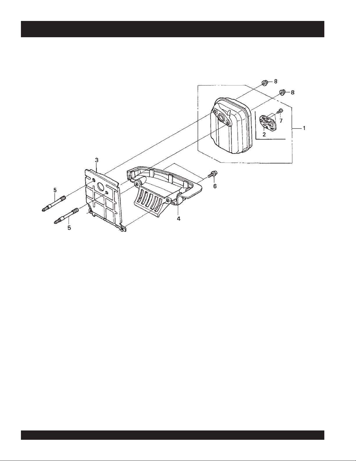
MUFFLER ASSY.
HONDA GX35SAT ENGINE — MUFFLER ASSY.
l
PAGE 56 — DSGPULW DUOSCREED — OPERATION AND PARTS MANUAL — REV. #6 (12/10/10)
Page 57

HONDA GX35SAT ENGINE — MUFFLER ASSY.
MUFFLER ASSY.
NO. PART NO. PART NAME QTY. REMARKS
1 18310Z0Z800 MUFFLER ............................................. 1 ........... INCLUDES ITEMS W/
2
3 18515Z0Z300 GUIDE, AIR 1
4 18518Z0Z000 GUIDE, AIR LOWER 1
5 90001Z0Z003 BOLT 2, STUD 5X45.5 2
6 90018Z0H003 BOLT, SOCKET 5X16 2
7
8 90136SM4901 NUT, SELF-LOCK 5MM 2
18350Z0Z800 ARRESTER SPARK 1
*
90055ZE1000 SCREW, TAPPING 4X6 3
*
*
DSGPULW DUOSCREED — OPERATION AND PARTS MANUAL — REV. # 6 (12/10/10) — PAGE 57
Page 58

ENGINE TOP COVER ASSY.
HONDA GX35SAT ENGINE — ENGINE TOP COVER ASSY.
l
PAGE 58 — DSGPULW DUOSCREED — OPERATION AND PARTS MANUAL — REV. #6 (12/10/10)
Page 59

HONDA GX35SAT ENGINE — ENGINE TOP COVER ASSY.
ENGINE TOP COVER ASSY.
NO. PART NO. PART NAME QTY. REMARKS
1 19720Z0Z000ZA COVER, TOP *R280* POWER RED 1
2 90015Z0H003 BOLT, TOP COVER 1
DSGPULW DUOSCREED — OPERATION AND PARTS MANUAL — REV. # 6 (12/10/10) — PAGE 59
Page 60

LABELS ASSY.
HONDA GX35SAT ENGINE — LABELS ASSY.
l
PAGE 60 — DSGPULW DUOSCREED — OPERATION AND PARTS MANUAL — REV. #6 (12/10/10)
Page 61

HONDA GX35SAT ENGINE — LABELS ASSY.
LABELS ASSY.
NO. PART NO. PART NAME QTY. REMARKS
2 87521Z0Z000 MARK, EMBLEM 1
3 87531Z0Z000 MARK, HONDA 1
4 87601Z0H860 MARK, TYPE SAT 1
6 87660Z0Z000 MARK, 4-STROKE 1
DSGPULW DUOSCREED — OPERATION AND PARTS MANUAL — REV. # 6 (12/10/10) — PAGE 61
Page 62

TERMS AND CONDITIONS OF SALE — PARTS
PAYMENT TERMS
Terms of payment for parts are net 30 days.
FREIGHT POLICY
All parts orders will be shipped collect or
prepaid with the charges added to the invoice.
All shipments are F.O.B. point of origin.
Multiquip’s responsibility ceases when a
signed manifest has been obtained from the
carrier, and any claim for shortage or damage
must be settled between the consignee and
the carrier.
MINIMUM ORDER
The minimum charge for orders from Multiquip
is $15.00 net. Customers will be asked for
instructions regarding handling of orders not
meeting this requirement.
RETURNED GOODS POLICY
Return shipments will be accepted and
credit will be allowed, subject to the following
provisions:
A Returned Material Authorization 1.
must be approved by Multiquip prior to
shipment.
To obtain a Return Material Authorization, 2.
a list must be provided to Multiquip
Parts Sales that defines item numbers,
quantities, and descriptions of the items
to be returned.
The parts numbers and descriptions a.
must match the current parts price
list.
The list must be typed or computer b.
generated.
The list must state the reason(s) c.
for the return.
The list must reference the sales d.
order(s) or invoice(s) under
which the items were originally
purchased.
The list must include the name e.
and phone number of the person
requesting the RMA.
A copy of the Return Material Authorization 3.
must accompany the return shipment.
Freight is at the sender’s expense. All 4.
parts must be returned freight prepaid to
Multiquip’s designated receiving point.
l
Parts must be in new and resalable 5.
condition, in the original Multiquip
package (if any), and with Multiquip part
numbers clearly marked.
The following items are not returnable:6.
Obsolete parts. (If an item is in the a.
price book and shows as being
replaced by another item, it is
obsolete.)
Any parts with a limited shelf life b.
(such as gaskets, seals, “O” rings,
and other rubber parts) that were
purchased more than six months
prior to the return date.
Any line item with an extended c.
dealer net price of less than
$5.00.
Special order items.d.
Electrical components.e.
Paint, chemicals, and lubricants.f.
Decals and paper products.g.
Items purchased in kits.h.
The sender will be notified of any material 7.
received that is not acceptable.
Such material will be held for five 8.
working days from notification, pending
instructions. If a reply is not received
within five days, the material will be
returned to the sender at his expense.
Credit on returned parts will be issued 9.
at dealer net price at time of the original
purchase, less a 15% restocking
charge.
In cases where an item is accepted, for 10.
which the original purchase document
can not be determined, the price will be
based on the list price that was effective
twelve months prior to the RMA date.
Credit issued will be applied to future 11.
purchases only.
PRICING AND REBATES
Prices are subject to change without prior
notice. Price changes are effective on a
specific date and all orders received on or
after that date will be billed at the revised price.
Rebates for price declines and added charges
for price increases will not be made for stock
on hand at the time of any price change.
Multiquip reserves the right to quote and
sell direct to Government agencies, and to
Original Equipment Manufacturer accounts
who use our products as integral parts of their
own products.
SPECIAL EXPEDITING SERVICE
A $35.00 surcharge will be added to the
invoice for special handling including bus
shipments, insured parcel post or in cases
where Multiquip must personally deliver the
parts to the carrier.
LIMITATIONS OF SELLER’S LIABILITY
Multiquip shall not be liable hereunder for
damages in excess of the purchase price of
the item with respect to which damages are
claimed, and in no event shall Multiquip be
liable for loss of profit or good will or for any
other special, consequential or incidental
damages.
LIMITATION OF WARRANTIES
No warranties, express or implied, are
made in connection with the sale of parts or
trade accessories nor as to any engine not
manufactured by Multiquip. Such warranties
made in connection with the sale of new,
complete units are made exclusively by a
statement of warranty packaged with such
units, and Multiquip neither assumes nor
authorizes any person to assume for it
any other obligation or liability whatever in
connection with the sale of its products. Apart
from such written statement of warranty,
there are no warranties, express, implied or
statutory, which extend beyond the description
of the products on the face hereof.
Effective: February 22, 2006
PAGE 62 — DSGPULW DUOSCREED — OPERATION AND PARTS MANUAL — REV. #6 (12/10/10)
Page 63

NOTE PAGE
DSGPULW DUOSCREED — OPERATION AND PARTS MANUAL — REV. # 6 (12/10/10) — PAGE 63
Page 64

OPERATION AND PARTS MANUAL
©
HERE’S HOW TO GET HELP
PLEASE HAVE THE MODEL AND SERIAL
NUMBER ON-HAND WHEN CALLING
UNITED STATES
Multiquip Corporate Offi ce MQ Parts Department
18910 Wilmington Ave.
Carson, CA 90746
Contact: mq@multiquip.com
Service Department Warranty Department
Tel. (800) 421-1244
Fax (800) 537-3927
800-427-1244
310-537-3700
Fax: 800-672-7877
Fax: 310-637-3284
800-421-1244
310-537-3700
Technical Assistance
800-478-1244 Fax: 310-943-2238
Fax: 310-537-4259 800-421-1244
310-537-3700
Fax: 310-537-1173
MEXICO UNITED KINGDOM
MQ Cipsa Multiquip (UK) Limited Head Offi ce
Carr. Fed. Mexico-Puebla KM 126.5
Momoxpan, Cholula, Puebla 72760 Mexico
Contact: pmastretta@cipsa.com.mx
Tel: (52) 222-225-9900
Fax: (52) 222-285-0420
Unit 2, Northpoint Industrial Estate,
Globe Lane,
Dukinfi eld, Cheshire SK16 4UJ
Contact: sales@multiquip.co.uk
Tel: 0161 339 2223
Fax: 0161 339 3226
CANADA
Multiquip
4110 Industriel Boul.
Laval, Quebec, Canada H7L 6V3
Contact: jmartin@multiquip.com
COPYRIGHT 2010, MULTIQUIP INC.
Multiquip Inc and the MQ logo are registered trademarks of Multiquip Inc. and may not be used, reproduced, or altered without written permission. All other trademarks are the property
of their respective owners and used with permission.
This manual
The information and specifications included in this publication were in effect at the time of approval for printing. Illustrations, descriptions, references and technical data contained in
this manual are for guidance only and may not be considered as binding. Multiquip Inc. reserves the right to discontinue or change specifications, design or the information published
in this publication at any time without notice and without incurring any obligations.
MUST accompany the equipment at all times. This manual is considered a permanent part of the equipment and should remain with the unit if resold.
Tel: (450) 625-2244
Tel: (877) 963-4411
Fax: (450) 625-8664
Your Local Dealer is:
 Loading...