

Page 1

PARTS AND OPERATION MANUAL
DS-Series
DuoScreed
(CHINA)
© COPYRIGHT 2001, MULTIQUIP INC.
Revision #0 (09/19/01)
MULTIQUIP INC
18910 WILMINGTON AVE. 800-427-1244
CARSON, CALIFORNIA 90746 FAX: 800-672-7877
310-537-3700
800-421-1244 800-478-1244
FAX: 310-537-3927 FAX: 310-537-4259
E-mail:mq@multiquip.com • www:multiquip.com
Atlanta • Boise • Dallas • Houston • Newark
Montreal, Canada • Manchester, UK
Rio De Janiero, Brazil • Guadalajara, Mexico
..
. PARTS DEPARTMENT:
..
SERVICE DEPARTMENT:
Page 2

l
PAGE 2 — DS-SERIES DUOSCREED — PARTS & OPERATION MANUAL — REV. #0 (09/19/01)
Page 3

HERE'S HOW TO GET HELP
PLEASE HAVE THE MODEL AND SERIAL NUMBER
ON-HAND WHEN CALLING
PARTS DEPARTMENT
800-427-1244 or 310-537-3700
FAX: 800-672-7877 or 310-637-3284
SERVICE DEPARTMENT/TECHNICAL ASSISTANCE
800-478-1244 or 310-537-3700
FAX: 310- 537-4259
WARRANTY DEPARTMENT
888-661-4279, or 310-661-4279
FAX: 310- 537-1173
MAIN
800-421-1244 or 310-537-3700
FAX: 310-537-3927
DS-SERIES DUOSCREED — PARTS & OPERATION MANUAL — REV. #0 (09/19/01) — PAGE 3
Page 4

TABLE OF CONTENTS
Here's How To Get Help ............................................ 3
Table Of Contents ..................................................... 4
Parts Ordering Procedures ....................................... 5
Rules For Safe Operation ...................................... 6-7
Operation and Safety Decals .................................... 8
Specifications ............................................................ 9
General Information ................................................ 10
Multiquip DS-Series —
Vibratory DuoScreed
Components (DuoScreed) ...................................... 11
Components (Honda GX31SA Engine) .................. 12
Assembly Instructions ........................................ 13-15
Starting ................................................................... 16
Application/Operation......................................... 17-20
Maintenance ...................................................... 21-22
Troubleshooting (DuoScreed) ................................. 23
Troubleshooting (Honds GX31SA Engine).............. 24
Explanation Of Codes In Remarks Column ............ 26
Suggested Spare Parts ........................................... 27
Main Assembly ................................................... 28-31
Name Plate And Decals ..................................... 32-33
Honda GX31SA Engine
Crankcase Assembly .........................................34-35
Camshaft Assembly ...........................................36-37
Piston Crankshaft Assembly ..............................38-39
Carburetor Assembly .........................................40-41
Recoil Starter Assembly.....................................42-43
Flywheel/Ignition Coil Assembly.........................44-45
Fuel Tank............................................................46-47
Air Cleaner Assembly.........................................48-49
Muffler Assembly ...............................................50-51
Clutch/Fan Cover Assembly ............................... 52-53
Engine Cover Assembly .....................................54-55
Terms and Conditions Of Sale — Parts .................. 56
l
NOTE
Specification and part number
are subject to change without
notice.
PAGE 4 — DS-SERIES DUOSCREED — PARTS & OPERATION MANUAL — REV. #0 (09/19/01)
Page 5

PARTS ORDERING PROCEDURES
n
Dealer account number
n
Dealer name and address
n
Shipping address (if different than billing address)
n
Return fax number
n
Applicable model number
n
Quantity, part number and description of each part
n
Specify preferred method of shipment:
UPS Ground
•
UPS Second Day or Third Day*
•
UPS Next Day*
•
Federal Express Priority One (please provide us with your Federal
•
Express account number)*
Airborne Express*
•
Truck or parcel post
•
*Normally shipped the same day the order is received, if prior to 2PM west coast time.
Earn Extra Discounts when
you order by FAX!
All parts orders which include complete part numbers
and are received by fax qualify for the following extra
discounts:
Number of
line items ordered Additional Discount
1-9 items 3%
10+ items** 5%
Get special freight allowances
when you order 10 or more
line items via FAX!**
n
UPS Ground Service at no charge for freight
n
UPS Third Day Service at one-half of actual freight
cost
No other allowances on freight shipped by any other carrier.
**Common nuts, bolts and washers (all items under $1.00 list price)
do not count towards the 10+ line items.
Extra Fax DiscountExtra Fax Discount
Extra Fax Discount
Extra Fax DiscountExtra Fax Discount
for Domestic USAfor Domestic USA
for Domestic USA
for Domestic USAfor Domestic USA
Dealers OnlyDealers Only
Dealers Only
Dealers OnlyDealers Only
Now! Direct TOLL-FREE access
to our Parts Department!
Toll-free nationwide:
800-421-1244
Toll-free FAX:
*DISCOUNTS ARE SUBJECT TO CHANGE*
Fax order discount and UPS special programs revised June 1, 1995
DS-SERIES DUOSCREED — PARTS & OPERATION MANUAL — REV. #0 (09/19/01) — PAGE 5
800/6-PARTS-7 • 800-672-7877
Page 6

DS-SERIES DUOSCREED — RULES FOR SAFE OPERATION
■
CAUTION:
Failure to follow instructions in this manual
may lead to serious injury or even death!
This equipment is to be operated by trained
and qualified personnel only! This
equipment is for industrial use only.
The following safety guidelines should always be used when
operating the DuoScreed
GENERAL SAFETY
■
DO NOT operate or service this equipment before
reading this entire manual.
■
This equipment should not be operated by persons under 18
years of age.
■
NEVER operate this equipment without proper
protective clothing, shatterproof glasses, steeltoed boots and other protective devices required
by the job.
NEVER touch the hot exhaust
manifold, muffler or cylinder.
Allow these parts to cool before
servicing engine or Duoscreed.
■
High Temperatures – Allow the engine to cool before adding
fuel or performing service and maintenance functions. Contact
hot
with
■
The DuoScreed engine requires an adequate free flow of
cooling air. Never operate the DuoScreed in any enclosed or
components can cause serious burns.
narrow area where free flow of the air
is restricted. If the air flow is restricted
it will cause serious damage to the
DuoScreed or engine and may cause
injury to people. Remember the
DuoScreed's engine gives off DEADLY
carbon monoxide gas.
■
NEVER operate this equipment when not
feeling well due to fatigue, illness or taking
medicine.
■
NEVER operate this equipment under the
influence or drugs or alcohol.
■
l
■
NEVER use accessories or attachments, which are not
recommended by Multiquip for this equipment. Damage to
the equipment and/or injury to user may result.
■
Manufacturer does not assume responsibility for any accident
due to equipment modifications.
■
Whenever necessary, replace nameplate, operation and
safety decals when they become difficult read.
■
Always check the machine for loosened threads or bolts before
starting.
■
■
Always refuel in a well-ventilated area, away from sparks and
open flames.
■
Always use extreme caution when
working with flammable liquids. When
refueling, stop the engine and allow it
to cool. DO NOT
the machine. Fire or explosion could
result from fuel vapors, or if fuel is spilled
on a hot engine.
NEVER operate the DuoScreed in an explosive atmosphere
or near combustible materials. An explosion or fire could result
causing severe
Topping-off to filler port is dangerous, as it tends to spill fuel.
bodily harm or even death.
smoke around or near
PAGE 6 — DS-SERIES DUOSCREED — PARTS & OPERATION MANUAL — REV. #0 (09/19/01)
Page 7

DS-SERIES DUOSCREED — RULES FOR SAFE OPERATION
■
Always read, understand, and follow procedures in Operator’s
Manual before attempting to operate equipment.
■
Always be sure the operator is familiar with proper safety
precautions and operations techniques before using
DuoScreed.
■
Refer to the
technical questions or information.
■
NEVER use accessories or attachments, which are not
HONDA Engine Owner's Manual
for engine
recommended by Multiquip for this equipment. Damage to
the equipment and/or injury to user may result.
■
NEVER Run engine without air cleaner. Severe engine
damage may occur.
■
Always service air cleaner frequently to prevent carburetor
malfunction.
■
Always store equipment properly when it is not being used.
Equipment should be stored in a clean, dry location out of the
reach of children.
Transporting
■
■
■
■
Emergencies
■
Maintenance Safety
■
■
Always shutdown engine before transporting.
Tighten fuel tank cap securely and close fuel cock to prevent
fuel from spilling.
Drain fuel when transporting DuoScreed over long distances
or bad roads.
Always tie-down the DuoScreed during transportation by
securing the DuoScreed with rope.
Always know the location of the nearest
and
first aid kit
. Know the location of the nearest telephone.
Also know the phone numbers of the nearest
doctor
and
fire department
. This information will be
fire extinguisher
ambulance
,
invaluable in the case of an emergency.
NEVER lubricate components or attempt service on a running
machine.
Always allow the machine a proper amount of time to cool
before servicing.
■
Keep the machinery in proper running condition.
■
Fix damage to the machine immediately and always replace
broken parts.
■
Dispose of hazardous waste properly. Examples of potentially
hazardous waste are used motor oil, fuel and fuel filters.
■
DO NOT use plastic containers to dispose of hazardous
waste.
■
DO NOT pour waste, oil or fuel directly onto the ground,
down a drain or into any water source
DS-SERIES DUOSCREED — PARTS & OPERATION MANUAL — REV. #0 (09/19/01) — PAGE 7
Page 8
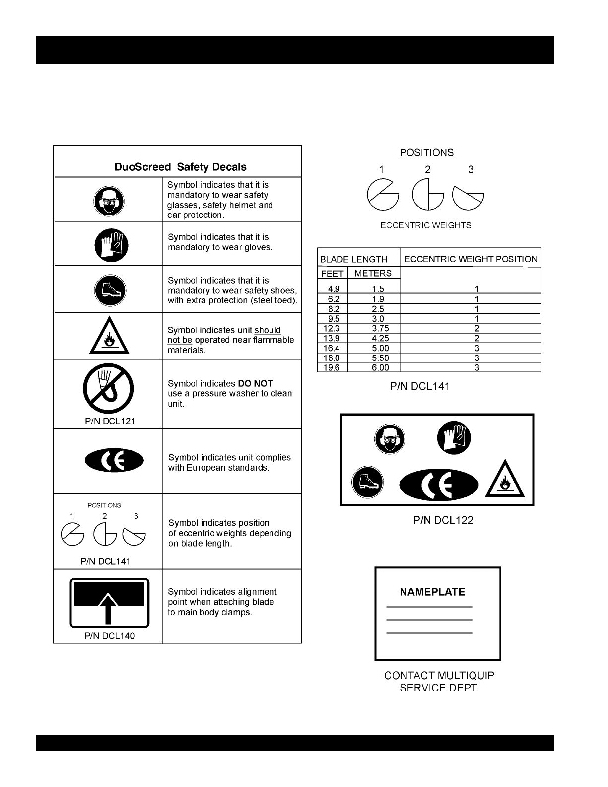
DS-SERIES DUOSCREED — OPERATION AND SAFETY DECALS
Machine Safety Decals
The DUOSCREED is equipped with a number of safety decals. These decals are provided for operator safety and maintenance
information. The illustrations below shows these decals as they appear on the machine. Should any of these decals become
unreadable, replacements can be obtained from your dealer.
l
PAGE 8 — DS-SERIES DUOSCREED — PARTS & OPERATION MANUAL — REV. #0 (09/19/01)
Page 9

DS-SERIES DUOSCREED — SPECIFICATIONS
ledoMtinUrewoPUPG-SD
snoitarbiVforebmuNnim/v005,5
metsySevirDtfahSelbixelF
)riAnepO(esioN)A(Bd05
SNOITACIFICEPSDEERCSOUD.1ELBAT
noitareleccAnoitarbiVces/m5.1
thgieWgnitarepO).gK61(.sbl53
noitcurtsnoCedalByollAmunimulAdedurtxE
shtdiWedalB
sthgieWedalB.tf/.bl8.2.xorppA
ekaMenignEADNOH
ledoMenignEAS-13XG
epyTenignEenignEenilosaGVHOekortS-4
thgieWenignE)gK3.3(.sbl5.7
srednilyCfOrebmuN1
2
.tf6.91,0.81,4.61,9.31,3.21,8.9,2.8,2.6,9.4
)sretem0.6,5.5,0.5,52.4,57.3,0.3,5.2,9.1,5.1(
SNOITACIFICEPSENIGNE.2ELBAT
3
tnemecalpsiDmc13(ni.uc9.1
)
tuptuOmumixaMmpr000,7/PHB5.1
edarGliO03-W01EAS
yticapaCliO)sretil01.0(/.tq11.0
epyTleuFdedaelnU
yticapaCknaTleuF)sretil56.(/.lag271.
paGgulPkrapS
epyTgulPkrapS
hcni820.0-420.0
)mm070-06.0(
)KGN(BSH5RC
)OSNED(BU-RSF61U
dohteMgnitratStratSlioceR
DS-SERIES DUOSCREED — PARTS & OPERATION MANUAL — REV. #0 (09/19/01) — PAGE 9
Page 10

DS-SERIES DUOSCREED — GENERAL INFORMATION
Introduction
This DuoScreed is a hand held vibratory screed designed to
strike-off and consolidate concrete slabs. It is comprised of two
major components, the power unit (gasoline engine), and the
strike-off blade. Generally this screed operates ideally in
concrete with a slump of 2 inches or greater. Its applications
include patios, driveways, sidewalks and floor slabs.
Assembly
There are no tools required to assemble the DuoScreed. The
power unit (engine) is connected to the to the blade by means of
a spring-loaded clamp. Springs within the clamp assembly
prevent vibration from loosening the power unit from the blade.
It takes approximately 2 minutes to assemble the DuoScreed.
Handle Adjustments
The handle assembly on the DuoScreed is height adjustable for
operator comfort. The handle design used on this screed allows
the operator to remain upright at all times and can be quickly
adjusted without any tools.
Vibratory System
The vibratory system of the DuoScreed produces low amplitude
high frequency vibrations, designed to level and compact
concrete. This vibratory system is mounted at an angle to transmit
vibration laterally and vertically through the blade to produce a
strong, dense slab.
Engine
The DuoScreed is equipped with an Honda Model GX31SA, 1.5
HP, mini 4-cycle gasoline engine. This engine is lightweight
and requires no fuel mixing.
Drive System
The Honda 1.5 HP engine drives a flexible shaft that requires no
greasing. Its short one piece design runs directly to the vibrator
housing and does not bend. This type of design eliminates a
major source of friction and reduces the likelihood of shaft failure.
Maneuverability
End caps are provided on each side of the DuoScreed's blades
to allow the screed to be easily maneuvered around pipes or
obstructions.
Transport
To transport your DuoScreed simply unclamp the power unit
from its base. Additionally, the handles can be folded down for
storage. The power unit weights approximately 34 pounds while
the blades weigh approximately 2.8 pounds per foot.
The engine drives a two piece eccentric weight by means of a
one-piece flexible shaft. This weight produces a vibratory action
which simultaneously allows the DuoScreed to level the slab
and consolidate the concrete beneath the surface.
Blades
The DuoScreed can utilize blades ranging in lengths from 4.9 to
19.6 feet (1.5 to 6 meters). Since different length blades will
require varying amounts of vibration, the DuoScreed features
adjustable eccentric weights. It is also recommended that two
power units be used if 16, 18, or 20 foot blades are required.
The blade of the DuoScreed offer a unique design with two
distinct edges and is manufactured from reinforced extruded
aluminum alloy. A curled edge is provided for applications that
allow the blade to ride on top of forms or rails. A smooth edge is
provided for wetscreed applications where the machine rides
entirely on concrete. Plastic end caps allow the blade to maneuver
around obstructions without marring the surface.
l
PAGE 10 — DS-SERIES DUOSCREED — PARTS & OPERATION MANUAL — REV. #0 (09/19/01)
Page 11

Figure 2. DuoScreed Components
DS-SERIES DUOSCREED — COMPONENTS
Figure 1 shows the location of the components of the DuoScreed.
The function of each component is described below:
1. Oil Cap – Remove this cap to add engine oil.
2. Fuel tank – Remove the fuel tank cap to add unleaded
fuel ONLY! DO NOT mix fuel. DO NOT over fill. Tank
holds approximately .172 gallons (.65 liters)
3. Throttle Control – Move the throttle lever to the
position for full throttle (max RPM's), for engine idle, move
up
the throttle lever to the
4. Handle Bar Adjustment Knobs – Loosen these two
knobs to adjust the handle bar to a suitable working position.
5. Handle Bar – Used in the steering of DuoScreed.
6. Hand Grip – When operating the DuoScreed use this hand
grip to maneuver the machine.
7. Support Stand Latch – Use this latch to lock support
stand in place when DuoScreed is in operation.
8. Engine ON/OFF Switch – Set this switch in the ON
position to start the engine, set in the OFF position to stop
the engine.
9. Support Stand – Use this stand to support the DuoScreed
when not in use.
position.
down
11. Spring-Loaded Wing Nuts– Turn these 3 spring loaded
wing nuts counterclockwise to release the blade from the
aluminum clamping strip, turn clockwise to secure the blade
to the clamping strip.
12. Blade – The DuoScreed comes in various blade sizes
ranging from 4.95 to 19.6 feet.
13. Locking Nuts – These 3 locking nuts are used in
conjunction with the 3 spring loaded wing nuts which
secure the blade to the aluminum clamping strip. Important!
always cover the two outer nuts with the provided plastic
cap. This will prevent concrete and other debris from
entering the quick disconnect system.
14. Eccentric Cover – Encloses the adjustable eccentric
weights.
15. Gasoline Engine – This DuoScreed uses a HONDA
GX31SA engine. Refer to the
engine information and related topics.
16. End Caps – Allows the DuoScreed to be maneuvered
around pipe or obstructions.
17. Flexible Drive Shaft– Connected to the drive shaft of the
engine, provides the vibrational force for the eccentric
weights.
HONDA
owners manual for
10. Shock Mounts – Used to absorb the vibration generated
by the DuoScreed. These shock mounts minimize the
transfer of vibration to the operator.
DS-SERIES DUOSCREED — PARTS & OPERATION MANUAL — REV. #0 (09/19/01) — PAGE 11
18. Lifting Bar– To lift or transport the DuoScreed, grab this
bar .
Page 12
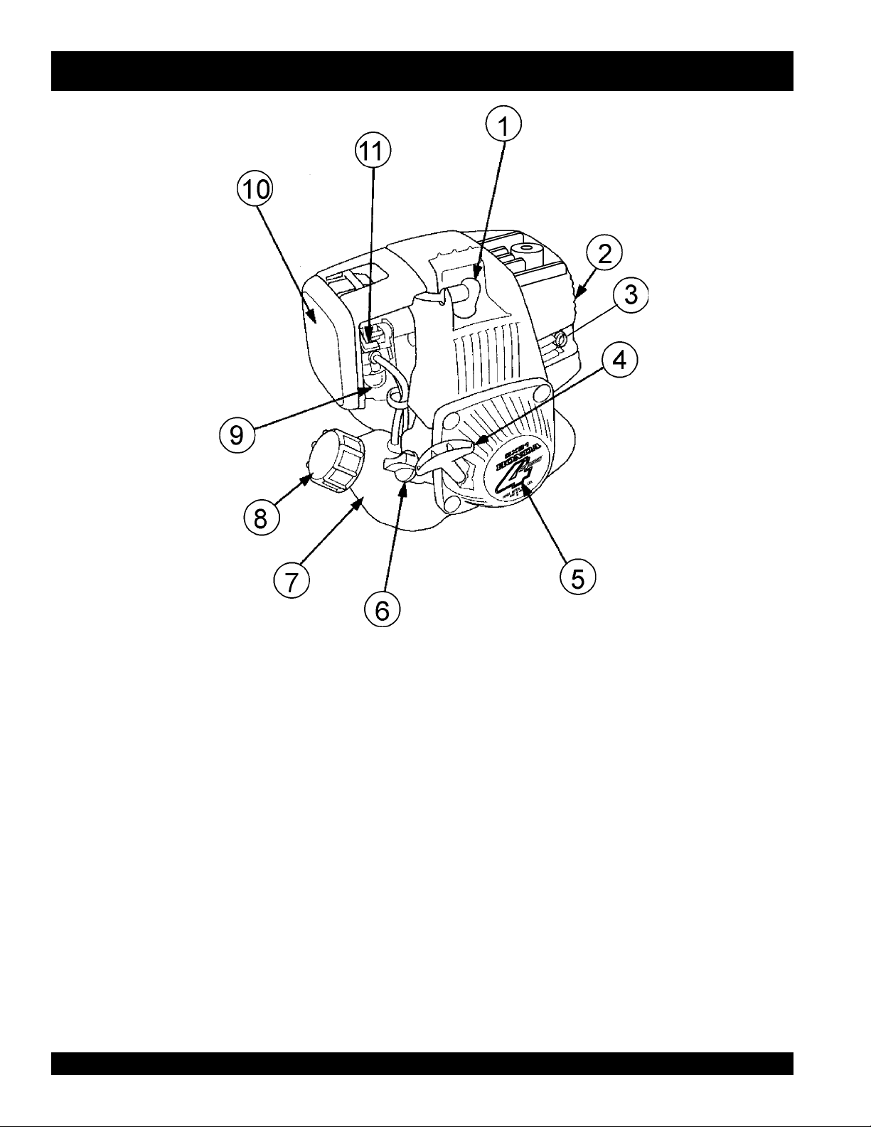
DS-SERIES DUOSCREED — COMPONENTS (HONDA GX31SA ENGINE)
Figure 2. HONDA GX31SA Components
1. Spark Plug – Provides spark to the ignition system. Set
spark plug gap to 0.6 - 0.7 mm (0.024 - 0.028 inch) Clean
spark plug once a week.
2. Muffler – Used to reduce noise and emissions. DO NOT
touch muffler while engine is running, let engine cool before
performing any maintenance.
3. Spark Arrester – Prevents sparks from leaving the engine
exhaust system, which could ignite flammable materials.
4. Starter Grip – Grip this handle to start engine. See engine
starting section of this manual.
5. Recoil Starter (pull rope) – Type of engine starting method.
6. Oil Filler Cap – Remove this cap to add engine oil. Engine
oil capacity is 0.11 quart (0.1 liters). Use SAE 10W-30.
PAGE 12 — DS-SERIES DUOSCREED — PARTS & OPERATION MANUAL — REV. #0 (09/19/01)
l
7. Fuel Tank – Holds .65 liters (approximately .172 gallon) of
8. Fuel Filler Cap – Remove this cap to add unleaded
9. Priming Bulb – Used in the starting of a cold engine or an
10. Air Cleaner – Prevents dirt and other debris from entering
11. Choke Lever – Used in the starting of a cold engine, or in
unleaded gasoline.
gasoline to the fuel tank. Make sure cap is tighten securely.
DO NOT over fill.
engine that has run out of fuel. Press the priming bulb
repeatedly until fuel can be seen inside the clear plastic
bulb.
the fuel system. Release latch on side of air filter
compartment to gain access to filter element.
cold weather conditions. The choke enriches the fuel mixture
for starting a cold engine.
Page 13

DS-SERIES DUOSCREED — ASSEMBLY INSTRUCTIONS
Assembly Instructions
This section will explain how to assemble the DuoScreed.
NOTE
It is recommended that you familiarize yourself with the
DuoScreed’s components. For assistance identifying
components called out in the text, refer to the Figure 1.
1. The DuoScreed is comprised of two major components.
The power unit (HONDA GX31SA Engine) and the strikeoff blade. This DuoScreed is equipped with a quick
disconnect system, with which the power unit can be
mounted onto two aluminum clamping strips with ease.
2. The aluminum clamping strip (retaining plate) is located at
the base of the power unit. This clamping strip is what
holds the blade in place with the aid of three quick
disconnect spring loaded wing nuts (Figure 3) that can
either be tighten or loosened by hand.
3. Determine whether you will be using the DuoScreed on
forms
unit will be mounted
screed the wing nuts should be located above the smooth
edge of the blade. If the DuoScreed will be used on forms
(Figure 3) the wing nuts should be located above the
curled edge of the blade.
4. Loosen each of the three wing nuts about 1/4 inch (8 mm).
It is not necessary to completely remove the wing nuts from
the aluminum clamping strip.
5. Locate the two red indicator arrows (Figure 4) on the top of
the blade. The power unit should be placed squarely
between the two markers.
or as a
wet screed
. This will decide how the power
.
If the DuoScreed will be used as a wet
Figure 3. Blade Quick Disconnect System
DS-SERIES DUOSCREED — PARTS & OPERATION MANUAL — REV. #0 (09/19/01) — PAGE 13
Page 14

DS-SERIES DUOSCREED — ASSEMBLY INSTRUCTIONS
Figure 4. Blade Mounting Diagram
6. Place the front of the power unit over the blade (Figure 3)
until the front of the clamp is seated within the front blade
collar.
7. Ease the power unit back to allow the rear clamp to seat
itself within the rear blade collar. It may be necessary to
further loosen the wing nuts to allow the clamp to fit around
the blade collar.
8. Securely hand tighten each of the three wing nuts. The
wing nuts are spring loaded to prevent them from coming
loose during operation.
l
9. Two handle bar adjustment knobs (Figure 5) are located at
the base of the steering handle bar. Loosen these two knobs
to adjust the height of the steering handle bar to a suitable
working position.
10. The DuoScreed is now ready for operational use.
Figure 5. Handle Bar Adjustment Knob
PAGE 14 — DS-SERIES DUOSCREED — PARTS & OPERATION MANUAL — REV. #0 (09/19/01)
Page 15
DS-SERIES DUOSCREED — ASSEMBLY INSTRUCTIONS
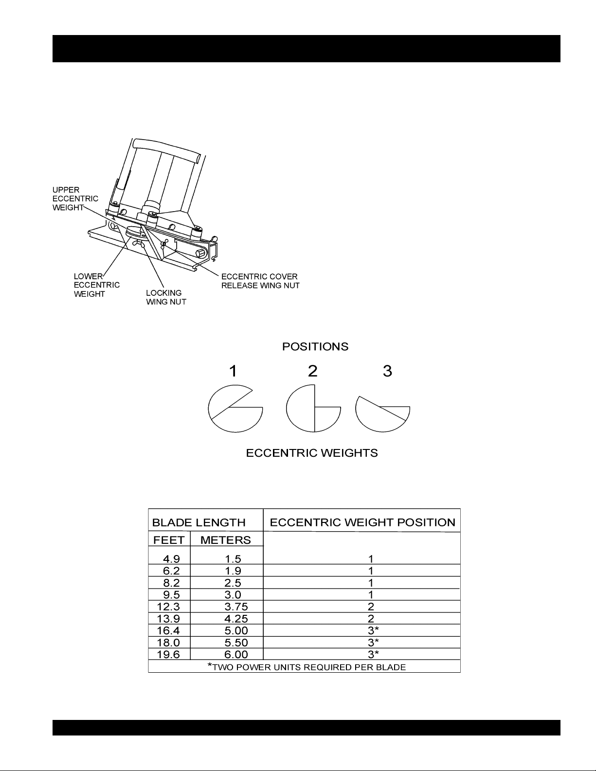
Eccentric Weight Adjustment
There are two eccentric weights (Figure 6) that are supplied
with the DuoScreed. These weights are located inside the
eccentric weight compartment, which is located at the bottom of
the unit.
Figure 6. Eccentric Weight Location
These weights determine the amount of vibration that will travel
down the blade. Depending on the type of blade that is used, will
determine the position of the two eccentric weights. Reference
Figure 7 in determining how your eccentric weights should be
positioned.
1. To gain access to the eccentric weight compartment, loosen
the two wing nuts on each side of the compartment and lift
the cover.
2. Loosen the eccentric locking wing nut.
3. Use the chart in Figure 7 to determine what position your
eccentric weights should be in (position 1, 2 or 3).
Example:
A 13.9 ft. (4.25 meters) blade will place the eccentric weights in
position 2.
Figure 7. Eccentric Weight Positions
DS-SERIES DUOSCREED — PARTS & OPERATION MANUAL — REV. #0 (09/19/01) — PAGE 15
Page 16

DS-SERIES DUOSCREED — STARTING
Engine Pre-Check
1. Fill the fuel tank (Figure 8 ) with unleaded gasoline. DO NOT
over fill. Topping-off to filler port is dangerous, as it tends to
spill fuel. Wipe up any spilled fuel immediately.
Figure 8. Fuel Tank
1. Place the engine in a level position.
2. Check the engine oil level by unscrewing the engine oil dip
stick (Figure 9) from its holder.
3. If oil is not observed at the edge of the oil filler hole, fill with
oil until oil is present at edge of oil filler hole. Remember to
add oil slowly to avoid overflowing, as the engine oil tank
capacity is small.
2. Press the priming bulb (Figure 11) repeatedly until fuel can
be seen inside the clear plastic bulb.
3. Set the engine ON/OFF switch (Figure 12) to the ON position.
Figure 11. Priming Bulb Location
Figure 9. Engine Oil Dipstick/Oil Filler Hole
4. Reinstall the engine oil dipstick securely.
Starting The Engine
1. To start a cold engine, move the choke lever (Figure 10) to
the CLOSED position. If restarting a warm engine leave the
choke lever in the OPEN position.
Figure 10. Choke Lever
l
Figure 12. Engine ON/OFF Switch
4. Pull the starter rope (Figure 13) lightly until you feel resistance, the pull briskly. Return the starter rope gently.
Figure 13. Engine Starter Rope
5. Once the engine has started, allow it to idle for 3 to 5 minutes.
PAGE 16 — DS-SERIES DUOSCREED — PARTS & OPERATION MANUAL — REV. #0 (09/19/01)
Page 17

Application/Operation
DS-SERIES DUOSCREED — APPLICATION/OPERATION
1. Before placing the DuoScreed in concrete for screeding,
it is a good idea to apply
frame parts that may come in contact with the concrete.
This form oil will become useful when cleaning the
DuoScreed. Make sure to
amount of form oil.
2. Prepare a grid of #5 rebar pins (Figure 14) equally spaced
approximately every 9 to 11 feet. If a 10 ft. screed blade
is going to be used space the grade pins every 9 feet, if
a 12 ft. screed blade is required, space the grade pins
every 11 ft. Make sure to drive the pins deeply into the
ground.
3. Use a
string line
The grade should be to the top of the grade pins. Remember, before any concrete is to be poured, make sure that
the top of the pins are dead on grade.
or
form oil
saturate the unit with a good
laser
to set the pins to grade (height).
to the blade and all
4. Once all the grade pins have been placed correctly and
are dead on grade, concrete can then be poured on top
of grade pins.
5. Level, and form the concrete as close as possible to
grade. Mark the top of each pin so that its exact location
will be known. Use a hand trowel to float the edges and
plumbing grade pins.
6. If chalk lines are used for grade against forms, walls or
existing concrete, float out the grade with a hand float
along the edge.
7. Two workers will be required to assist the DuoScreed
operator when making the 12-18 concrete bases, one on
each side. These workers will rake the concrete in toward
the center of the DuoScreed away form the bases to avoid
changing base elevation.
Figure 14. DuoScreed On Forms and Grade Pins
DS-SERIES DUOSCREED — PARTS & OPERATION MANUAL — REV. #0 (09/19/01) — PAGE 17
Page 18

DS-SERIES DUOSCREED — APPLICATION/OPERATION
14. Remember to build the bases in long parallel strips
across the pins and on the hand floated edges and
against plumbing or other outs, leaving the long unfinished areas about 8 or 9 feet wide. Once the bases are
built, the workers can more accurately shape the concrete
to grade.
15. When
his two workers can begin to work down the long parallel
unfinished 8 to 9 foot wide middle portions. When moving the
DuoScreed down the middle portions, the ends of the
Figure 15. Throttle Lever
NOTE
Before placing the DuoScreed in concrete, make certain
the unit has been set up (blade) for
can be verfied by observing that the operator's toes are
pointing towards the smooth side of the blade (Figure 3),
from the operators's position (handle bars).
8. Set the DuoScreed blade down in the concrete base in the
left
most corner of the grid between the two grade pins as
shown in Figure 16. Adjust the DuoScreed's handle bar
to a height where the operators is not bending over, but
standing upright with arms extended forward.
9. To begin screeding move the engine throttle lever (Figure
15) midway between idle and full throttle. Notice that the
DuoScreed's vibration will cause the blade to sink into the
concrete base until it touches the top of the grade pins
10. Pull the DuoScreed from the edge of the grid's
corner, horizontally toward the
DuoScreed passes over the grade pins a small circle of
concrete around the grade pins will appear. This indicates
that the Duoscreed has vibrated the grade pin, and that
the operators is
11. Keep the DuoScreed blade level and create a level base
between 12-18 inches wide.
12. After a complete pass over the first set of grade pins has
been made, remove the DuoScreed from the concrete
base and position it over the second set of grade pins
(Figure 16), overlapping the first set of grade pins between 12-18 inches. Repete this process until all
grade pins have a level base between 12-18 inches wide.
dead on grade
wet screeding
center
. Notice that as the
l
.
. This
top left
left
edge
DuoScreed blade should be resting on the bases, and the
leading edge of the blade should be approximately 1/8 to
1/4 inch above each base depending on the slump and
condition of the concrete. Have workers adjust the concrete
along the face of the DuoScreed's blade to assure that the
base is level with no high or low areas ahead of the blade.
16. Keep the engine throttle between 1/2 to 2/3 of full speed, if
necessary readjust the DuoScreed's vibration to meet the
condition of the concrete. Remember to move rapidly and
watch both ends of the blade to assure that the blade remains
1/8 to 1/4 of an inch above the concrete base. Always keep
the workers alert for concrete height changes.
Shut-Down
1. NEVER
speed.
2. Move the engine
speed position (idle).
3. Set the engine ON/OFF switch (Figure 12) to the OFF
position.
4. Remove the DuoScreed from the slab surface.
Cleaning
1. Allow the engine to
has cooled, use a damp and a mild detergent to remove all
concrete and foreign debris. DO NOT spay the engine with
water.
2. To remove all concrete and foreign debris from the
DuoScreed, wash the DuoScreed's blade and frame using
water and a mild detergent. Remember, if form oil was
applied before the machine was placed in concrete, the
cleanup will be much easier.
all
the bases have been completed, the operator and
stop
the engine suddenly while running at high
throttle lever
cool
before cleaning. When the engine
(Figure 15) to the low
13. Repeat steps 9 through 12 pulling the DuoScreed from
the edge of the grid's
the center.
PAGE 18 — DS-SERIES DUOSCREED — PARTS & OPERATION MANUAL — REV. #0 (09/19/01)
top right
corner, horizontally toward
Page 19

DS-SERIES DUOSCREED — APPLICATION/OPERATION
TOP LEFT
CORNER OF
GRID
STEP 1
PLACE # 5 REBAR GRADE PINS
AND FORM RECTANGULAR GRID.
BLADE OVERLAP
12-18 INCHES
STEP 2
POUR CONCRETE
AND FORM TO GRADE
12-18 INCH
BASE
HORIZONTAL
DIRECTION
DUOSCREED BLADE
HORIZONTAL
DIRECTION
HORIZONTAL
DIRECTION
HORIZONTAL
DUOSCREED BLADE
DIRECTION
STEP 7
DUOSCREED BLADE
VERTICAL
DIRECTION
STEP 7
SET SCREED BLADE DOWN ON
UNFINISHED 8 TO 9 FT. WIDE
MIDDLE SECTION, PLACING
BOTH ENDS OF THE BLADE
ON THE 12-18 INCH BASES.
STEP 7
12-18 INCH
BASE
HORIZONTAL
DIRECTION
HORIZONTAL
DIRECTION
HORIZONTAL
DIRECTION
HORIZONTAL
DIRECTION
DUOSCREED BLADE
BLADE OVERLAP
12-18 INCHES
DUOSCREED BLADE
TOP RIGHT
CORNER OF
GRID
STEP 3
MAKE 12-18 INCH
BASE (LEFT SIDE)
STARTING IN THE TOP LEFT CORNER OF GRID,
BUILD 18 INCH WIDE PARALLEL CONCRETE BASES
ACROSS GRADE PINS FROM TOP TO BOTTOM OF GRID.
STEP 4
APPROX.
8-9 FT.
RECTANGULAR
GRID
STARTING IN THE TOP RIGHT CORNER OF GRID,
BUILD 18 INCH WIDE PARALLEL CONCRETE BASES
ACROSS GRADE PINS FROM TOP TO BOTTOM OF GRID.
STEP 6
Figure 16. DuoScreed Wet Screeding Application
STEP 5
MAKE 12-18 INCH
BASE (RIGHT SIDE)
DS-SERIES DUOSCREED — PARTS & OPERATION MANUAL — REV. #0 (09/19/01) — PAGE 19
Page 20

DS-SERIES DUOSCREED — APPLICATION/OPERATION
Important Tips to Remember
■
Do not allow the engine to run out of fuel as this may cause
problems with starting. Always maintain an extra supply of
fuel on the job site.
■
Always keep the DuoScreed moving backwards during
operation. Allowing the DuoScreed to vibrate in the same
location for too long will cause it to sink into the concrete.
■
When using the DuoScreed with low slump (dry) concrete do
not attempt to walk it quickly across the slab. Walk slowly to
allow the vibratory action to consolidate and level the slab
surface. When using the DuoScreed with high slump (wet)
concrete you will be able to walk the machine across the slab
at a faster pace.
■
In applications where the Duoscreed is being used as a wet
screed it is recommended that grade or height of the concrete
slab be adjusted with a laser device.
■
Proper vibratory force is essential to producing a
durable
eccentric weights
troubleshooting section of this manual.
■
When screeding using forms or rails, always size your screed
blade appropriately for the job. It is best to have the blade
extend beyond the forms, by about 6-inches on each side.
slab. If the DuoScreed is vibrating too strongly the
will require adjustment. Refer to the
level, hard
■
■
■
■
■
■
■
,
When screeding make sure the blade is kept straight. DO
NOT let blade turn.
DO NOT run the DuoScreed with one part of the blade on
forms and the other on base. The blade must either be placed
on forms or float (wet screeding), but not a combination of the
two techniques.
DO NOT stand in the concrete with the engine throttle
engaged. This will cause the DuoScreed to sink.
If the concrete appears too wavy, you are moving too slowly,
increase your backing-up speed.
Always keep the workers back far enough too allow the
operator to see the cutting face of the blade as it rides on the
wet screed base.
The operator should keep the screed blade about 1/8 to 1/4
inch above the concrete base at all times.
Should the DuoScreed stick to the wet concrete slab, DO
NOT attempt to lift it. Quickly increase engine rpm's while
pushing forward on the handles to free the machine.
l
PAGE 20 — DS-SERIES DUOSCREED — PARTS & OPERATION MANUAL — REV. #0 (09/19/01)
Page 21

DS-SERIES DUOSCREED — MAINTENANCE
Maintenance
3. Use a low pressure water hose, soft brush, wiping cloth
CAUTION:
DO NOT clean the DuoScreed with a
pressure washer
.
1. NEVER clean the DuoScreed with the engine running.
2. Allow the engine to cool down before cleaning.
NOTE
DO NOT allow concrete to
harden
on the
DuoScreed. Wipe all concrete off the chrome
frame and any other parts including the engine
of the DuoScreed.
)3(NOITPIRCSEDNOITAREPOEROFEB
4. Keep the drive unit free from grease, dirt and grime as this
30 - Day Storage Procedure
For storage of the DuoScreed for over 30 days, the following is
required:
l
l
l
l
TSRIF
HTNOM
RO
.SRH01
and a mild cleaning detergent and remove all concrete
from the DuoScreed. Be careful not to get excessive amounts
of water in the engine compartment.
can effect the performance of your DuoScreed
Drain the fuel tank completely.
Run the engine until the fuel in the injection system is
completely consumed.
Completely drain used oil from the engine crankcase and
fill with fresh clean oil, then follow the procedures described
in the engine manual for engine storage.
Cover DuoScreed and engine with plastic covering or
equivalent and store in a clean, dry place.
eludehcSecnanetniaMenignE.3elbaT
YREVE
SHTNOM3
RO
.SRH52
YREVE
SHTNOM6
RO
.SRH05
YREVE
RAEY
RO
.SRH001
YREVE
SRAEY2
RO
.SRH002
liOenignE
renaelCriA
stloB&stuNllA
gulPkrapS
sniFgnilooCKCEHCX
retserrAkrapSNAELC X
knaTleuFNAELC X
retliFleuFKCEHC X
seohShctulCKCEHC)2(X
deepSeldITSUJDA-KCEHC )2(X
ecnaraelCevlaVTSUJDA-KCEHC )2(X
senilleuFKCEHC )2()yrassecenfiecalper(sraey2yrevE
KCEHCX
EGNAHCX
KCEHCX
EGNAHC)1(X
fInethgit-eR
yrasseceN
NAELC-KCEHCX
ECALPER X
X
nidesunehwyltneuqerferomecivreS)1( YTSUD .saera
yllacinahcemeradnaslootreporpehtevahuoysselnu,relaedcivresruoyybdecivresebdluohssmetiesehT)2(
serudecorpecivresroflaunaMpohsADNOHehtotrefeR.tneiciforp
.slavretniecnanetniamreporpenimretedotnoitarepofosruohgol,esulaicremmocroF)3(
DS-SERIES DUOSCREED — PARTS & OPERATION MANUAL — REV. #0 (09/19/01) — PAGE 21
Page 22

DS-SERIES DUOSCREED — MAINTENANCE
Air Cleaner
1. The air cleaner element should be cleaned because a
clogged air cleaner can cause poor engine starting, lack of
power and shorten engine life substantially.
2. Before opening the air cleaner compartment, wipe any dirt
or foreign matter from the air cleaner body and cover, using
a moist cloth. Be careful to prevent dirt from entering the
carburetor
3. Press the latch tab on the top of the air cleaner cover (Figure
16), and remove the cover. Check the filter to be sure that it
is clean and in good condition.
3. Remove the spark plug with 5/8-inch wrench.
4. Inspect the spark plug. Replace it if the electrodes are worn,
or if the insulator is cracked or chipped. Clean the spark
plug with a wire brush if you are going to reuse it.
5. Set the spark plug gap (Figure 18) using a suitable gauge.
The gap should be between 0.024-0.028 inch (0.60-0.70
mm).
6. Carefully install the spark plug by hand to avoid cross
threading, the tighten
Figure 18. Spark Plug Gap
7. Attach spark plug cap.
Figure 16. Air Cleaner
Spark Plug
1. Make sure the engine is off and cool.
2. Disconnect the spark plug cap ( Figure 17), and remove
any dirt from around the spark plug area.
l
Figure 17. Spark Plug Removal
PAGE 22 — DS-SERIES DUOSCREED — PARTS & OPERATION MANUAL — REV. #0 (09/19/01)
Page 23

DS-SERIES DUOSCREED — TROUBLESHOOTING
GNITOOHSELBUORTDEERCSOUD.4ELBAT
MOTPMYSESUACELBISSOPNOITULOS
tessirotarbivehtfoecroflagufirtnecehT
?woloot
ehttluserasadnatneiciffusnisetarbiV
dnadelevelebtonnacroolfetercnoc
.yawreporpehtnidehtooms
?egral
-mrofasadesunehwdeercSouDehT
dnahcumootsetarbivdeercsmrof-ot
liarehtssorcaylhtoomslevarttonseod
.stroppus
deercsehtsa"YVAW"skooletercnoC
.tirevosessapedalb
tewgnirudstopsWOLroHGIHgnivaeL
.gnideercs
?hctamton
?ylwolsootgnivomrotarepO
?etercnoc
etercnocfostnuomaevissecxesierehT
?edalbehtfoegdegnidaelehtgnola
ootsiedalbehtfohtdiwnesohcehT
odsthgiewcirtneccednaedalbdetceleS
foepytehtrofnoitarbivhcumooT
?edisenonowolrohgihootetercnoC
.deeps
.edalbehtmorf
)senigne2(.tf02
.ecap
sthgiewcirtnecceehttsujdA
enigneesaercniro7erugiFrep
etercnocevissecxeehtevomeR
edalbrellamsahtiwkroW
sihtdiwmumixamrebmemeR
otsthgiewcirtneccetsujdA
.htdiwedalbdetceleshctam
.7erugiFecnerefeR
retsafatasdrawkcabklaW
klawdnadeepsenigneecudeR
.ecapretsafatasdrawkcab
ehtepahssrekrowevaH
otelbissopsaesolcetercnoc
fohcni1tuobaniatniaM.edarg
fotnorfehtssorccaetercnoc
.semitllataedalbeht
.etercnoctewotnisgidedalB?yltcerrocdenoitisopedalbsI
tsumedalbehtfodnehcaE
.ecafrusemasehtnoedir
edalbehtfodnehcaerehtiE
tew(etercnocrosmrofnosedir
.htobton)deercs
DS-SERIES DUOSCREED — PARTS & OPERATION MANUAL — REV. #0 (09/19/01) — PAGE 23
Page 24

DS-SERIES DUOSCREED — TROUBLESHOOTING
GNITOOHSELBUORTENIGNE.5ELBAT
MOTPMYSESUACELBISSOPNOITULOS
?gnigdirbgulpkrapS
ontub,elbaliavasileuf",tratsottluciffiD
."gulpkrapstaKRAPS
?noitalusni
?evitcefedliocnoitingI.liocnoitingiecalpeR
dna,elbaliavasileuf",tratsottluciffiD
."gulpkrapsehttatneserpsiKRAPS
?gnitiucric
?epytleufgnorW
?gulpkrapsnotisopednobraC .gulpkrapsecalperronaelC
gulpkrapstneicifedoteudtiucrictrohS
?paggulpkrapsreporpmI.pagreporpotteS
?detrohssihctiwsFFO/NO
?yrtridstniop,pagkrapsreporpmI
trohsronrownoitalusniresnednoC
?gnitiucrictrohsronekorberiwgulpkrapS
.nrowfiecalper
.hctiws
.stniopnaelc
.gniriw
ronoitalusni,pagkcehC
.gulpkrapsecalper
,noitalusnigulpkrapskcehC
ecalper,gniriwhctiwskcehC
dnapagkrapstcerrocteS
.resnednocecalpeR
gulpkrapsevitcefedecalpeR
ecalperdna,metsysleufhsulF
.leuffoepyttcerrochtiw
kraps,elbaliavasileuf",tratsottluciffiD
"lamronsinoisserpmocdnatneserpsi
?ytridrenaelcriA .renaelcriaecalperronaelC
?nepOekohC.ekohCesolC
l
kraps,elbaliavasileuf",tratsottluciffiD
"wolsinoisserpmocdnatneserpsi
?ylreporpdenethgit
?degamad
?deggolcretlifleuF.retlifleufecalpeR
.blubgnimirpedisnitneserpleufoN
?enilleufniriA.enilleufdeelB
?metsysleufnitsudroretaW.metsysleufhsulF
?dedurtorprokcutsevlavtsuahxe/noitcuS.sevlavtaes-eR
?nrowrednilycro/dnagnirnotsiP
tongulpkrapsro/dnadaehrednilyC
teksaggulpkrapsro/dnateksagdaeH
?knatleufnielbaliavatonleuF .leuffoepyttcerrochtiwlliF
?deggolcelohrehtaerbpacknatleuF .packnatleufecalperronaelC
rodnasgnirnotsipecalpeR
.notsip
dnastlobdaehrednilyceuqroT
.gulpkraps
gulpkrapsdnadaehecalpeR
.steksag
PAGE 24 — DS-SERIES DUOSCREED — PARTS & OPERATION MANUAL — REV. #0 (09/19/01)
Page 25

NOTE PAGE
DS-SERIES DUOSCREED — PARTS & OPERATION MANUAL — REV. #0 (09/19/01) — PAGE 25
Page 26

DUOSCREED — EXPLANATION OF CODE IN REMARKS COLUMN
How to read the marks and remarks used in this parts
book.
Items Found In the “Remarks” Column
Serial Numbers-Where indicated, this indicates a serial
number range (inclusive) where a particular part is used.
Model Number-Where indicated, this shows that the
corresponding part is utilized only with this specific model
number or model number variant.
Items Found In the “Items Number” Column
All parts with same symbol in the number column,
■
, belong to the same assembly or kit.
If more than one of the same reference number is
listed, the last one listed indicates newest (or latest)
part available.
, #, +, %, or
*
l
NOTE
NOTE
The contents of this catalog are
subject to change without notice
PAGE 26 — DS-SERIES DUOSCREED — PARTS & OPERATION MANUAL — REV. #0 (09/19/01)
.
Page 27

DUOSCREED — SUGGESTED SPARE PARTS
DUOSCREED 1 TO 3 UNITS WITH HONDA
GX31SA ENGINE
1 to 3 Units
Qty. ....... P/N .............................. Description
2 ............ BF2648 ....................... HANDLE GRIP
1 ............ BF2647 ....................... THROTTLE GRIP
2 ............ BF2645 ....................... THROTTLE CABLE
1 ............ BF2621 ....................... FLEXIBLE SHAFT
1 ............ BF2609 ....................... ECCENTRIC COVER
3 ............ BF2607 ....................... COMPRESSION SPRING
1 ............ BF2605 ....................... ALUMINUM CLAMPING STRIP
3 ............ BF0176 ....................... WASHER
3 ............ BF2606 ....................... CLAMP
1 ............ BF2643 ....................... STOP SWITCH
3 ............ BF0325 ....................... WING NUT M6X12
3 ............ 9805655757 ................ SPARK PLUG
3 ............ 17211ZM3000 ............. ELEMENT AIR
1 ............ 15620ZM3003 ............. CAP, OIL FILLER
1 ............ 28400ZM3003ZA ........ RECOIL STARTER ASSY.
NOTE
Part numbers on this Suggested
Spare Parts List may supercede/
replace the P/N shown in the text
pages of this book.
DS-SERIES DUOSCREED — PARTS & OPERATION MANUAL — REV. #0 (09/19/01) — PAGE 27
Page 28
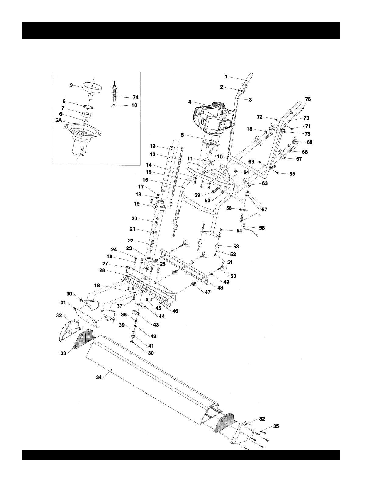
DUO SCREED MAIN ASSY.
DS-SERIES DUOSCREED — MAIN ASSY.
l
PAGE 28 — DS-SERIES DUOSCREED — PARTS & OPERATION MANUAL — REV. #0 (09/19/01)
Page 29

DS-SERIES DUOSCREED — MAIN ASSY.
DUO SCREED MAIN ASSY.
NO. PART NO. PART NAME QTY. REMARKS
1 BF2648 HANDLE GRIP 2
2 BF2647 THROTTLE HANDLE 1
3 BF2633 UPPER OPERATING HANDLE 1
4 BF2640A ENGINE HONDA GX 31SA (USA) 1
5 BF2641 CENTRIFUGAL CLUTCH HOUSING 1
COMPLETE ( EXCLUDING CLAMP 11 )
5A BF2641 CENTRIFUGAL CLUTCH HOUSING 1
WITH ALUMINUM RING
6 BF0201 RETAINING RING 17 X 1 MM 1
IN CENTRIFUGAL HOUSING
7 BF2642C BEARING IN CENTRIFUGAL HOUSING 1
8 BF0205 RETAING RING ( BIG ) 1
9 BF2642 CENTRIFUGAL DRUM 1
10 BF2645 THROTTLE ASM. CABLE 100CMS. 1
11 BF2626 CENTRIFUGAL HOUSING CLAMP 1
12 BF2625 RUBBER HOSE WITH CONNECTORS 1
13 BF2621 FLEXIBLE SHAFT 1
14 BF0178 SPRING WASHER M6 TYPE B 4
15 BF0165 SOCKET HEAD BOLT M6 X 25 4
16 BF2632 LOWER OPERATING HANDLE 1
17 BF0101 SELF LOCKING NUT M8 3
18 BF0155 FLAT WASHER M8 8
19 BF2611 ECCENTRIC HOUSING 1
20 BF1100000008 COUPLING DRIVE PIN 1
21 BF2619 BEARING (SMALL) 1
22 BF2612 ECCENTRIC SHAFT 1
23 BF2314 BEARING (BIG) 1
24 BF0125 TAP BOLT M8 X 16 4
25 BF0201 RETAINING RING 17 X 1MM 1
27 BF2604 ECCENTRIC ASSEMBLY PLATE 1
28 BF2610 STRIP & NUTS FOR ALUMINUM CLAMP 1
30 BF0325 WING NUT M6 X 12 3
31 BF2609 ECCENTRIC COVER 1
32 BF2602 ENDCAPS SET 1
33 BF2602A ALUMINUM BLADE SEALS SET (1 SIDE) 1
34 DUOSCREED BLADE 1.5 MTR. - 5 FT. ...................... 1 ........... ACCESSORY ITEM ORDER
DUOSCREED BLADE 1.9 MTR.- 6 FT. ....................... 1 ........... FROM UNIT SALES DEPT.
DUOSCREED BLADE 2.5 MTR. - 8 FT. ...................... 1 ........... "
DUOSCREED BLADE 3.0 MTR. - 10 FT. .................... 1 ........... "
DUOSCREED BLADE 3.75 MTR. - 12 FT. .................. 1 ........... "
DUOSCREED BLADE 4.25 MTR. - 14 FT. .................. 1 ........... "
DUOSCREED BLADE 5.0 MTR. - 16 FT. .................... 1 ........... "
DUOSCREED BLADE 5.50 MTR. - 18 FT. .................. 1 ........... "
DUOSCREED BLADE 6.0 MTR. - 20 FT. .................... 1 ........... "
DS-SERIES DUOSCREED — PARTS & OPERATION MANUAL — REV. #0 (09/19/01) — PAGE 29
Page 30

DUO SCREED MAIN ASSY.
DS-SERIES DUOSCREED — MAIN ASSY.
l
PAGE 30 — DS-SERIES DUOSCREED — PARTS & OPERATION MANUAL — REV. #0 (09/19/01)
Page 31

DS-SERIES DUOSCREED — MAIN ASSY.
DUO SCREED MAIN ASSY.
NO. PART NO. PART NAME QTY. REMARKS
35 BF0277 SELF TAPPING SCREW M5 X 20 12
37 BF0129 TAP BOLT M8 X 40 3
38 BF2614 ECCENTRIC HINGE BUSHING 1
39 BF0177 NUT M12 (FINE) 1
41 BF2613 ECCENTRIC CLAMPING BUSH 1
42 BF0175 RETAINING RING M12 1
43 BF2615A ECCENTRIC PLATE (SMALL) 1
44 BF2615B ECCENTRIC PLATE (BIG) 1
45 BF0229 COUNTERSUNK HEADSCREW 8.8 M8X20 4
46 BF2617 PLASTIC PROTECTION CAP M12 3
47 BF2607 COMPRESSION SPRING FOR CLAMPING STRIP 3
48 BF2605 ALUMINUM CLAMPING STRIP 1
49 BF0176 WASHER M12X6 3
50 BF2606 CLAMP FOR CLAMPING STRIP 3
51 BF0285 TAP BOLT M8X12 3
52 BF0212 INTERNAL TOOTHING RING M8 8
53 BF0056 RUBBER BUFFER 30X30 M8 4
54 BF0124 TAP BOLT M8X10 4
56 BF2643A EARTH WIRE FOR STOP SWITCH 1
57 BF2643 STOPSWITCH ...................................................................... 1 ..........INCLUDES ITEMS W/
58
*
59 BF0283 CARRIAGE BOLT M8X50 2
60 BF0089 SELF LOCKING FLANGE NUT M6 2
63 BF2635 LOWER ALUMINUM CLAMP 2
64 BF2649 RUBBER SLEEVE 1
65 BF0258 TAP BOLT M6X20 1
66 BF0100 SELF LOCKING NUIT 1
67 BF2635A UPPER ALUMINUM CLAMP 2
68 BF0284 SOCKET HEAD BOLT M6X40 2
69 BF2636 CLAMP FOR HEIGHT ADJUSTMENT 2
71 BF0261 SCREW M5X12 1
72 BF0099 SELF LOCKING NUT M5 1
73 BF2637 SUPPORTING LEG 1
74 BF2644 GAS THROTTLE ADJUSTMENT BOLT 1
75 BF2639 CLAMP FOR SUPPORTING LEG 1
76 BF2634 RUBBER PROTECTION CAP FOR SUPPORT LEG 1
ON-OFF INDICATION PLATE 1
*
DS-SERIES DUOSCREED — PARTS & OPERATION MANUAL — REV. #0 (09/19/01) — PAGE 31
Page 32

DS-SERIES DUOSCREED — NAME PLATE AND DECALS
NAME PLATE AND DECALS.
l
PAGE 32 — DS-SERIES DUOSCREED — PARTS & OPERATION MANUAL — REV. #0 (09/19/01)
Page 33

DS-SERIES DUOSCREED — NAME PLATE AND DECALS
NAME PLATE AND DECALS.
NO PART NO PART NAME QTY. REMARKS
1
*
2
*
3 PLATE, SERIAL NO. ......................... 1 ............ CONTACT MQ SERVICE DEPT. W/MODEL & S/N
4
*
SEE DECAL ILLUSTRATIONS ON PAGE 7.
DCL121 DECAL, PRESSURE HOSE 1
DCL122 DECAL, SAFETY 1
DCL140 DECAL, ALIGNMENT ARROWS ..... 2
DCLDS-SERIES KIT, DECAL ....................................... 1 ............ INCLUDES ITEMS W/
*
DS-SERIES DUOSCREED — PARTS & OPERATION MANUAL — REV. #0 (09/19/01) — PAGE 33
Page 34

CRANKCASE ASSY.
HONDA GX31SA ENGINE — CRANKCASE ASSY.
l
PAGE 34 — DS-SERIES DUOSCREED — PARTS & OPERATION MANUAL — REV. #0 (09/19/01)
Page 35

HONDA GX31SA ENGINE — CRANKCASE ASSY.
CRANKCASE ASSY.
NO. PART NO. PART NAME QTY. REMARKS
1 11010ZM5000 CRANKCASE SET.................................... 1.....
1 11010ZM5010 CRANKCASE SET.................................... 1..... INCLUDES ITEM W/
2 04102ZM3000 COVER COMP., HEAD ............................. 1..... INCLUDES ITEM W/# USE UP TO SN1040026
2 12310ZM3000 COVER COMP., HEAD ............................. 1..... INCLUDES ITEM W/# USE FROM SN1040027
3 12312ZM3000 GASKET, HEAD COVER .......................... 1..... USE UP TO SN1040026
3 12312ZM3010 GASKET, HEAD COVER .......................... 1..... USE FROM SN 1040027
4 14121ZM5000 COVER, CAMSHAFT 1
5
15511ZM3000 COVER, OIL OUTLET VALVE 1
*
6 15571ZM3003 VALVE, OIL OUTLET 1
7 15572ZM3000 PLATE, STOPPER 1
8 15620ZM3003 CAP, OIL FILTER 1
9 15625ZE1003 GASKET, OIL FILTER CAP 1
10*90003ZM3000 BOLT, FLANGE (5X55) 4
11*90005ZM3000 BOLT, FLANGE (5X18) 6
12 90011ZM3000 SCREW, PAN (6X8) 1
13 90002ZM3000 BOLT, FLANGE (5X14).............................. 1..... USE FROM SN 1040026
13 90101P4V000 BOLT, FLANGE (5X12).............................. 1..... USE UP TO SN 1040027
14 90001ZM3000 BOLT, FLANGE (5X22).............................. 2..... USE FROM SN 1040026
14 90112GK8010 BOLT, FLANGE (5X22).............................. 2..... USE UP TO SN 1040027
15 90481GW3000 WASHER, SEALING (6.5MM) 1
16# 91501ZM3000 COLLAR, HEAD COVER .......................... 2..... USE UP TO SN 1040026
16# 91501ZM3010 COLLAR, HEAD COVER .......................... 2..... USE FROM SN1040027
17# 91502ZM3000 COLLAR, HEAD COVER .......................... 1..... USE UP TO SN1040026
17# 91506ZM3000 COLLAR, HEAD COVER .......................... 1..... USE FROM SN 1040027
18 934010401600 BOLT-WASHER (4X16) 5
19 93500030050A SCREW, PAN (3X5) 1
20 95005700033M BULK HOSE, VACUUM(7X3000) (7X68) 1
21 9805655757 SPARK PLUG (U16FSR-UB) 1
21 9805655777 SPARK PLUG (R5HSB) 1
INCLUDES ITEM W/
*
*
DS-SERIES DUOSCREED — PARTS & OPERATION MANUAL — REV. #0 (09/19/01) — PAGE 35
Page 36

CAMSHAFT ASSY.
HONDA GX31SA ENGINE — CAMSHAFT ASSY.
l
PAGE 36 — DS-SERIES DUOSCREED — PARTS & OPERATION MANUAL — REV. #0 (09/19/01)
Page 37

HONDA GX31SA ENGINE — CAMSHAFT ASSY.
CAMSHAFT ASSY.
NO. PART NO. PART NAME QTY. REMARKS
1 14100ZM3000 CAMSHAFT ASSY. 1
2 14126ZM3000 ROLLER (5X23.8) 2
3 14410ZM3000 ROD, PUSH 2
4 14431ZM3000 ARM, VALVE ROCKER 2
5 14451ZM3000 PIVOT, ROCKER ARM 2
6 14711ZM5000 VALVE, IN. 1
7 14721ZM3000 VALVE, EX. 1
8 14731ZM3003 LIFTER, VALVE 2
9 14751ZM3000 SPRING, VALVE 2
10 14771ZM3000 RETAINER, VALVE SPRING 2
11 41313PL3000 ROLLER (4X28) 1
12 90206ZM3000 NUT, TAPPET ADJUSTING 2
DS-SERIES DUOSCREED — PARTS & OPERATION MANUAL — REV. #0 (09/19/01) — PAGE 37
Page 38

HONDA GX31SA ENGINE — PISTON/CRANKSHAFT ASSY.
PISTON CRANKSHAFT ASSY.
l
PAGE 38 — DS-SERIES DUOSCREED — PARTS & OPERATION MANUAL — REV. #0 (09/19/01)
Page 39

HONDA GX31SA ENGINE — PISTON/CRANKSHAFT ASSY.
PISTON CRANKSHAFT ASSY.
NO. PART NO. PART NAME QTY. REMARKS
1 13010ZM5000 RING SET, PISTON 1
2
3
4 13310ZM5000 CRANKSHAFT COMP. 1 INCLUDES ITEM W/* USE UP TO SN 1040026
4 13310ZM5020 CRANKSHAFT COMP. 1 INCLUDES ITEM W/* USE FROM SN 1040027
5 91213ZM3003 OIL SEAL (12X25X6) 1
6 91213ZM3003 OIL SEAL (12X25X6) 1 USE UP TO SN 1040026
6 91214ZM3003 OIL SEAL (15X25X6) 1 USE FROM SN 1040027
13101ZM5000 PISTON 1
*
13111ZM5000 PIN, PISTON 1
*
DS-SERIES DUOSCREED — PARTS & OPERATION MANUAL — REV. #0 (09/19/01) — PAGE 39
Page 40

CARBURETOR ASSY.
HONDA GX31SA ENGINE — CARBURETOR ASSY.
l
PAGE 40 — DS-SERIES DUOSCREED — PARTS & OPERATION MANUAL — REV. #0 (09/19/01)
Page 41

HONDA GX31SA ENGINE — CARBURETOR ASSY.
CARBURETOR ASSY.
NO. PART NO. PART NAME QTY. REMARKS
1
2
4
5
6
7
8#
9#
10#*16020ZM3004 SPRING, METERING LEVER 1
11#*16021ZM3004 SCREW, METERING LEVER PIN 1
12#*16022ZM3004 PIN, METERING LEVER 1
13#*16023ZM3004 LEVER, METERING 1
14
15
16
17
18
19
20
21
22
24 16100ZM5804 CARBURETOR ASSY. .................... 1 ....... INCLUDES ITEMS W/
25 16211ZM3000 INSULATOR, CARBURETOR 1
26 16212ZM3000 GASKET, INSULATOR 1
27 16221ZM3000 GASKET, CARBURETOR 1
28 19651ZM3000 GUIDE, AIR IN. 1
29 938940501000 SCREW-WASHER (5X10) 1
30 90010ZM3000 BOLT, HEX. (5X75) 2
31 90112GK8010 BOLT, FLANGE (5X22) 2
32 90659680013 CLIP, WIRE HARNESS 1
33 91301ZM3000 O-RING (14.8X2.4) 1
34
34
34
16010ZM3004 GASKET, METERING 1
*
16011ZM3014 GASKET, PUMP 1
*
16013ZM3004 DIAPHRAGM ASSY., 1
*
16014ZM3004 DIAPHRAGM, PUMP 1
*
16015ZM3004 BODY ASSY., PUMP ...................... 1 ....... NCLUDES ITEMS W/#
*
16017ZM3004 BODY ASSY., AIR PURGE 1
*
16018ZM3004 SCREEN, INLET 1
*
16019ZM3004 VALVE, IN. NEEDLE 1
*
16024ZM3004 RING, SPRING RETAINING 1
*
16025ZM3004 O-RING 1
*
16026ZM3004 COVER, PRIMER PUMP 1
*
16027ZM3004 SWIVEL 1
*
16028ZM3004 SCREW, THROTTLE COLLAR 2
*
16029ZM3004 SCREW, PUMP COVER 4
*
16030ZM3004 SPRING, PUMP 1
*
16031ZM3004 WASHER 1
*
16032ZM3004 PUMP, PRIMER 1
*
99101ZM30380 JET (#38) (OPTIONAL) 1
*
99101ZM30390 JET (#39) (OPTIONAL) 1
*
99101ZM30400 JET (#40) 1
*
DIAPHRAGM
METERING
*
DS-SERIES DUOSCREED — PARTS & OPERATION MANUAL — REV. #0 (09/19/01) — PAGE 41
Page 42

RECOIL STARTER ASSY.
HONDA GX31SA ENGINE — RECOIL STARTER ASSY.
l
PAGE 42 — DS-SERIES DUOSCREED — PARTS & OPERATION MANUAL — REV. #0 (09/19/01)
Page 43

HONDA GX31SA ENGINE — RECOIL STARTER ASSY.
RECOIL STARTER ASSY.
NO. PART NO. PART NAME QTY. REMARKS
1 28400ZM3003ZA RECOIL STARTER ASSY. .............. 1 ....... INCLUDES ITEMS W/
2
3
4
5
6 28447ZM3000 FAN, RACHET 1
7 28451ZM3003 PULLEY, RECOIL STARTER 1
8
9
10
11 90005ZM3000 BOLT, FLANGE (5X18) 4
12
13
14
28414ZM3003 CASE, RECOIL STARTER 1
*
28421ZM3003 REEL, RECOIL STARTER 1
*
28433ZM3003 GUIDE, ROPE 1
*
28442ZM3003 SPRING, RECOIL STARTER 1
*
28459ZM3003 SWING ARM 1
*
28461ZM3003 KNOB, RECOIL STARTER 1
*
28462ZM3003 ROPE, RECOIL STARTER 1
*
90012ZM3003 SCREW, SETTING 1
*
91504ZM3003 COLLAR 1
*
91505ZM3003 COLLAR 4
*
*
DS-SERIES DUOSCREED — PARTS & OPERATION MANUAL — REV. #0 (09/19/01) — PAGE 43
Page 44
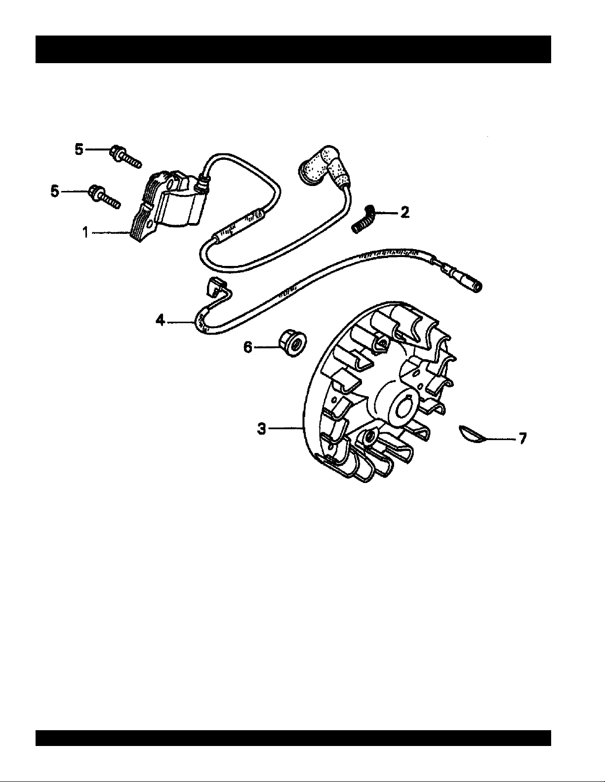
HONDA GX31SA ENGINE — FLYWHEEL/IGNITION COIL ASSY.
FLYWHEEL/IGNITION COIL ASSY.
l
PAGE 44 — DS-SERIES DUOSCREED — PARTS & OPERATION MANUAL — REV. #0 (09/19/01)
Page 45

HONDA GX31SA ENGINE — FLYWHEEL/IGNITION COIL ASSY.
FLYWHEEL/IGNITION COIL ASSY.
NO. PART NO. PART NAME QTY. REMARKS
1 30500ZM3003 COIL ASSY., IGNITION 1
2 30519ZM3000 TUBE A, CORRUGATED (7X18) 1
3 31110ZM5003 FLYWHEEL COMP. ....................... 1.......... USE UP TO SN 1040026
3 31110ZM5013 FLYWHEEL COMP. ....................... 1.......... USE FROM SN 1040027
4 32195ZM3000 WIRE, STOP SWITCH 1
5 934010501600 BOLT-WASHER (5X16) 2
6 9405008000 NUT, FLANGE (8MM) .................... 1.......... USE UP TO SN 1040026
6 9405010000 NUT, FLANGE (10MM) .................. 1.......... USE FROM SN 1040027
7 9440116120 KEY, WOODRUFF (16X12) 1
DS-SERIES DUOSCREED — PARTS & OPERATION MANUAL — REV. #0 (09/19/01) — PAGE 45
Page 46

FUEL TANK ASSY.
HONDA GX31SA ENGINE — FUEL TANK ASSY.
l
PAGE 46 — DS-SERIES DUOSCREED — PARTS & OPERATION MANUAL — REV. #0 (09/19/01)
Page 47

HONDA GX31SA ENGINE — FUEL TANK ASSY.
FUEL TANK ASSY.
NO. PART NO. PART NAME QTY. REMARKS
1 17504ZM3003 GROMMET, FUEL TUBE 1
2 17511ZM5003 TANK, FUEL 1
3 17532ZM3000 RUBBER, TANK MOUNTING .......... 1 ....... USE UP TO SN 1040026
3 17532ZM3010 RUBBER A, TANK MOUNTING ...... 1 ....... USE FROM SN 1040027
3 17533ZM3000 RUBBER B, TANK MOUNTING ...... 1 ....... USE UP TO SN 1040026
4 17561ZM3000 STAY, FUEL TANK........................... 1 ....... USE UP TO SN 1040026
4 17561ZM3010 STAY, FUEL TANK ........................... 1 ....... USE FROM SN 1040027
5 17620ZM3023 CAP ASSY., FUEL TANK ................ 1 ....... USE UP TO SN 1064797
5 17620ZM3033 CAP ASSY., FUEL TANK ................ 1 ....... USE FROM SN 1040027
6 17672ZM3003 FILTER, FUEL 1
7 17701ZM3003 TUBE, FUEL 1
8 17702ZM3003 TUBE, FUEL RETURN 1
9 91401ZM3003 CLIP, TUBE 2
10 17532ZM3000 RUBBER, TANK MOUNTING .......... 2 ....... USE UP TO SN 1040026
10 17533ZM3000 RUBBER B, TANK MOUNTING ...... 2 ....... USE UP TO SN 1040027
DS-SERIES DUOSCREED — PARTS & OPERATION MANUAL — REV. #0 (09/19/01) — PAGE 47
Page 48
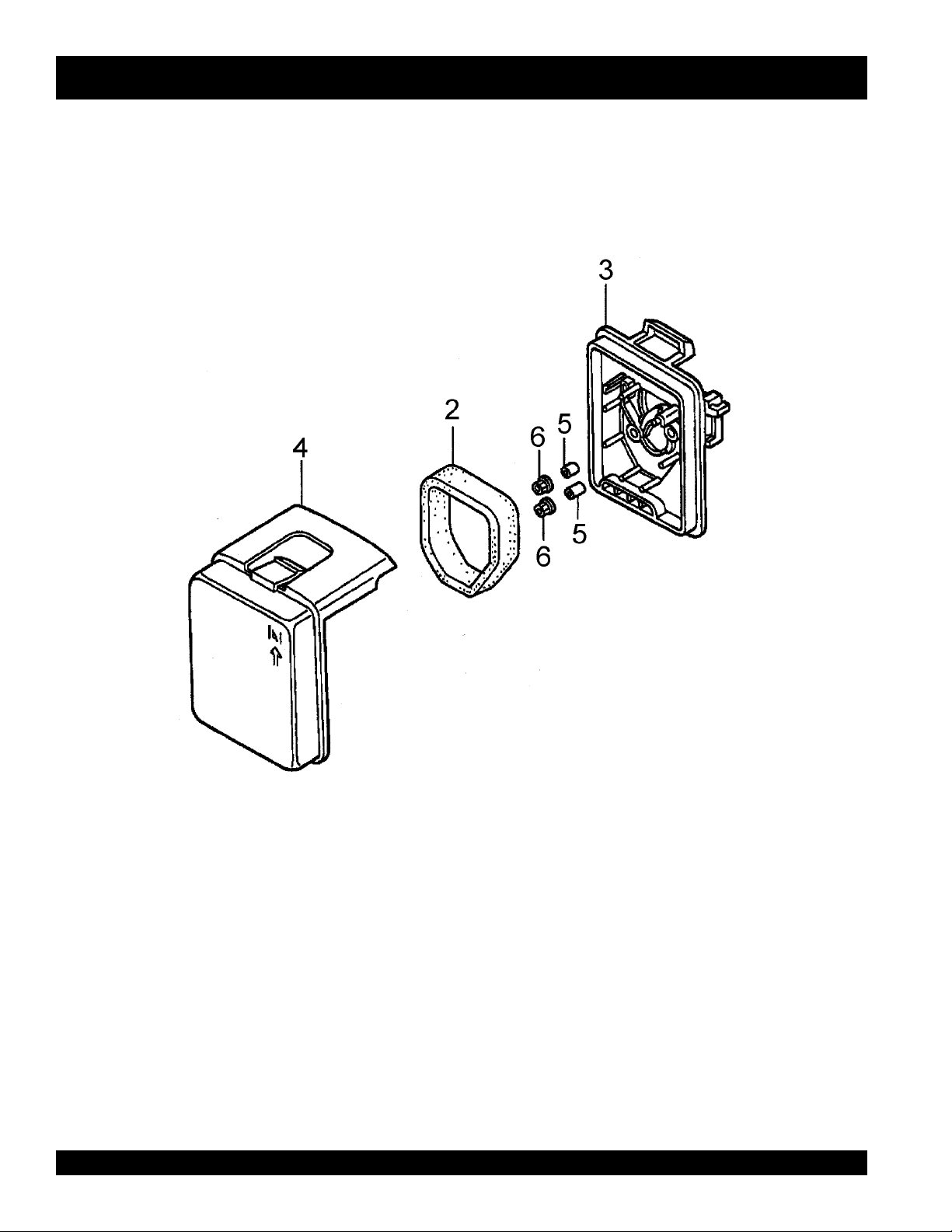
AIR CLEANER ASSY.
HONDA GX31SA ENGINE — AIR CLEANER ASSY.
l
PAGE 48 — DS-SERIES DUOSCREED — PARTS & OPERATION MANUAL — REV. #0 (09/19/01)
Page 49

HONDA GX31SA ENGINE — AIR CLEANER ASSY.
AIR CLEANER ASSY.
NO. PART NO. PART NAME QTY. REMARKS
2 17211ZM3000 ELEMENT, AIR CLEANER 1
3 17220ZM3000ZA HOUSING COMP., AIR CLEANER .......... 1........... BRIGHT RED
4 17231ZM3000ZA COVER, AIR CLEANER ........................... 1........... BRIGHT RED
5 91503ZM3000 COLLAR, AIR CLEANER 2
6 9405005000 NUT, FLANGE (5MM) 2
DS-SERIES DUOSCREED — PARTS & OPERATION MANUAL — REV. #0 (09/19/01) — PAGE 49
Page 50

MUFFLER ASSY.
HONDA GX31SA ENGINE — MUFFLER ASSY.
l
PAGE 50 — DS-SERIES DUOSCREED — PARTS & OPERATION MANUAL — REV. #0 (09/19/01)
Page 51

HONDA GX31SA ENGINE — MUFFLER ASSY.
MUFFLER ASSY.
NO. PART NO. PART NAME QTY. REMARKS
1 18310ZM3800 MUFFLER COMP. 1
2 18355ZM3801 ARRESTER ,SPARK 1
3 18515ZM3000 GUIDE, AIR EX. 1
4 19722ZM3000 INNER COVER, TOP ...................... 1 ....... USE UP TO SN 1007272
4 19722ZM3810 INNER COVER, TOP ...................... 1 ....... USE FROM SN 1007273
5 90004ZM3000 BOLT, FLANGE (5X50) 2
6 90055ZE1000 SCREW, TAPPING (4X6) 1
7 938910500800 SCREW - WASHER (5X8) 1
8 938940501000 SCREW - WASHER (5X10) 1
9 938940501600 SCREW - WASHER (5X16) 1
DS-SERIES DUOSCREED — PARTS & OPERATION MANUAL — REV. #0 (09/19/01) — PAGE 51
Page 52

HONDA GX31SA ENGINE — CLUTCH/FAN COVER ASSY.
l
PAGE 52 — DS-SERIES DUOSCREED — PARTS & OPERATION MANUAL — REV. #0 (09/19/01)
Page 53

HONDA GX31SA ENGINE — CLUTCH/FAN COVER ASSY.
CLUTCH/FAN COVER ASSY.
NO. PART NO. PART NAME QTY. REMARKS
1 19611ZM5000 COVER, FAN 1
2 22000ZM5003 CLUTCH ASSY. 1
3 22253ZM5003 BOLT, CLUTCH (8MM) 2
4 22254ZM5003 WASHER, CLUTCH (8X17) 2
5 90005ZM3000 BOLT, FLANGE (5X18) 2
DS-SERIES DUOSCREED — PARTS & OPERATION MANUAL — REV. #0 (09/19/01) — PAGE 53
Page 54

HONDA GX31SA ENGINE — ENGINE COVER ASSY.
l
PAGE 54 — DS-SERIES DUOSCREED — PARTS & OPERATION MANUAL — REV. #0 (09/19/01)
Page 55

HONDA GX31SA ENGINE — ENGINE COVER ASSY.
ENGINE COVER ASSY.
NO. PART NO. PART NAME QTY. REMARKS
1 19720ZM3000ZA COVER COMP., TOP *R8* .............. 1 ....... BRIGHT RED
2 90112GK8010 BOLT, FLANGE (5X22) 2
3 91502ZM3000 COLLAR, TOP COVER 2
DS-SERIES DUOSCREED — PARTS & OPERATION MANUAL — REV. #0 (09/19/01) — PAGE 55
Page 56

Effective: July 1, 2000
TERMS AND CONDITIONS OF SALE — PARTS
PAYMENT TERMS
Terms of payment for parts are net 10 days.
FREIGHT POLICY
All parts orders will be shipped collect or
prepaid with the charges added to the invoice.
All shipments are F.O.B. point of origin.
Multiquip’s responsibility ceases when a signed
manifest has been obtained from the carrier,
and any claim for shortage or damage must be
settled between the consignee and the carrier.
MINIMUM ORDER
The minimum charge for orders from Multiquip
is $15.00 net. Customers will be asked for
instructions regarding handling of orders not
meeting this requirement.
RETURNED GOODS POLICY
Return shipments will be accepted and credit
will be allowed, subject to the following
provisions:
1. A Returned Material Authorization must
be approved by Multiquip prior to shipment.
2. To obtain a Return Material Authorization,
a list must be provided to Multiquip Parts
Sales that defines item numbers,
quantities, and descriptions of the items to
be returned.
a. The parts numbers and descriptions
must match the current parts price
list.
b. The list must be typed or computer
generated.
c. The list must state the reason(s) for
the return.
d. The list must reference the sales
order(s) or invoice(s) under which
the items were originally purchased.
e. The list must include the name and
phone number of the person
requesting the RMA.
3. A copy of the Return Material
Authorization must accompany the return
shipment.
l
4. Freight is at the sender’s expense. All
5. Parts must be in new and resalable
6. The following items are not returnable:
7. The sender will be notified of any material
8. Such material will be held for 5 working
9. Credit on returned parts will be issued at
10. In cases where an item is accepted for
11. Credit issued will be applied to future
PRICING AND REBATES
parts must be returned freight prepaid to
Multiquip’s designated receiving point.
condition, in the original Multiquip package
(if any), and with Muiltiquip part numbers
clearly marked.
a. Obsolete parts. (If an item is listed
in the parts price book as being
replaced by another item, it is
obsolete.)
b. Any parts with a limited shelf life
(such as gaskets, seals, “O” rings,
and other rubber parts) that were
purchased more than six months
prior to the return date.
c. Any line item with an extended dealer
net price of less than $5.00.
d. Special order items.
e. Electrical components.
f. Paint, chemicals, and lubricants.
g. Decals and paper products.
h. Items purchased in kits.
received that is not acceptable.
days from notification, pending
instructions. If a reply is not received
within 5 days, the material will be returned
to the sender at his expense.
dealer net price at time of the original
purchase, less a 15% restocking charge.
which the original purchase document
can not be determined, the price will be
based on the list price that was effective
twelve months prior to the RMA date.
purchases only.
Prices are subject to change without prior
notice. Price changes are effective on a specific
date and all orders received on or after that date
will be billed at the revised price. Rebates for
price declines and added charges for price
increases will not be made for stock on hand at
the time of any price change.
Multiquip reserves the right to quote and sell
direct to Government agencies, and to Original
Equipment Manufacturer accounts who use
our products as integral parts of their own
products.
SPECIAL EXPEDITING SERVICE
A $20.00 to $50.00 surcharge will be added to
the invoice for special handling including bus
shipments, insured parcel post or in cases
where Multiquip must personally deliver the
parts to the carrier.
LIMITATIONS OF SELLER’S LIABILITY
Multiquip shall not be liable here under for
damages in excess of the purchase price of the
item with respect to which damages are claimed,
and in no event shall Multiquip be liable for loss
of profit or good will or for any other special,
consequential or incidental damages.
LIMITATION OF WARRANTIES
No warranties, express or implied, are made in
connection with the sale of parts or trade
accessories nor as to any engine not
manufactured by Multiquip. Such warranties
made in connection with the sale of new,
complete units are made exclusively by a
statement of warranty packaged with such
units, and Multiquip neither assumes not
authorizes any person to assume for it any
other obligation or liability whatever in
connection with the sale of its products. A part
from such written statement of warranty, there
are no warranties, express, implied or statutory,
which extend beyond the description of the
products on the face hereof.
PAGE 56 — DS-SERIES DUOSCREED — PARTS & OPERATION MANUAL — REV. #0 (09/19/01)
Page 57

NOTE PAGE
DS-SERIES DUOSCREED — PARTS & OPERATION MANUAL — REV. #0 (09/19/01) — PAGE 57
Page 58

PARTS AND OPERATION MANUAL
HERE'S HOW TO GET HELP
PLEASE HAVE THE MODEL AND SERIAL NUMBER
ON-HAND WHEN CALLING
PARTS DEPARTMENT
800-427-1244 or 310-537-3700
FAX: 800-672-7877 or 310-637-3284
SERVICE DEPARTMENT/TECHNICAL ASSISTANCE
800-478-1244 or 310-537-3700
FAX: 310- 537-4259
WARRANTY DEPARTMENT
888-661-4279, or 310-661-4279
FAX: 310- 537-1173
MAIN
800-421-1244 or 310-537-3700
FAX: 310-537-3927
MULTIQUIP INC
18910 WILMINGTON AVE. 800-427-1244
CARSON, CALIFORNIA 90746 FAX: 800-672-7877
310-537-3700
800-421-1244 800-478-1244
FAX: 310-537-3927 FAX: 310-537-4259
E-mail:mq@multiquip.com • www:multiquip.com
..
. PARTS DEPARTMENT:
..
SERVICE DEPARTMENT:
 Loading...