

Page 1
DIS185SSI4F Air Compressor
Hose Reel Kit Installation Instructions
The following instructions are intended to assist the user in the installation of the hose reel kit for use on the
DIS185SSI4F air compressor. Please read all installation instructions before installing the kit.
REQUIRED TOOLS
Power drill with 13/64", 11/32", and 3/4" drill bits
Metric/SAE ratchet set
Metric/SAE socket set
Wire cutters/strippers
1/2" thread sealant tape
Scriber or equivalent tool
PARTS
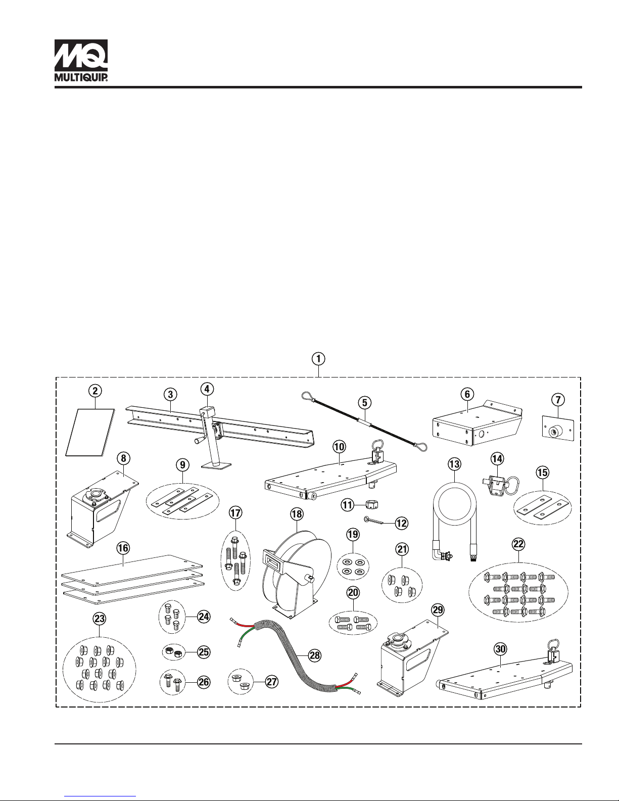
Verify that all parts are accounted for. See Figure 1 and Table 1.
INSTRUCTIONS
Figure 1. DIS185SSI4F Hose Reel Installation Kit
DIS185SSI4F AIR COMPRESSOR — HOSE REEL INSTALLATION INSTRUCTIONS P/N EE60468 — REV. #0 (04/16/18) — PAGE 1
Page 2
Table 1. DIS185SSI4F Hose Reel Installation Kit
Item
No.
1 MQPSINGLEREEL50
1 MQPDUALREEL50
2 EE60468
3 59269
4 29479
5 59274
6 59234 Plate, Pivot Base Mt 1
7 59267
8 59272
9 59286
10 59275
11 EM968481 Nut, Hex Slotted, 1-14 1
12 38709 Pin, Cotter 3/16 × 2" 1
13 59265 Hose Assembly 1
14 59251 Lock Pin Assembly 1
Part No. Description Qty. Remarks
Reel Kit Assembly, DIS185
50', Right
Reel Kit Assembly, DIS185
Dual 50'
Work Instruction, Reel Kit,
DIS185SSI4F
Bumper Assembly,
Hose Reel Kit
Jack, Sidewind 10"
Bolt-On, .5 Pin, Foot
Safety Cable Hose Whip
1/8 × 20"
Bump Stop Assembly,
Rear
Pivot Base Assembly,
Right
Shim, Pivot Plate Mt,
.075 Thk
Reel Mount Assembly,
Right
1
1
1
1
1
1
1
1
4
1
Includes
items 2–28
Includes
items 2–30
Double qty.
for dual kit
Double qty.
for dual kit
Double qty.
for dual kit
Double qty.
for dual kit
Double qty.
for dual kit
Double qty.
for dual kit
Double qty.
for dual kit
Double qty.
for dual kit
Table 1. DIS185SSI4F Hose Reel Installation Kit (Continued)
Item
No.
15 59289 Shim, Lock Latch 2
16 59290
17 42346
18 59263
19 0447 Washer, Flat SAE, 1/2" 4
20 5218 Bolt, HHC, 1/2-13 × 1-1/2" 4
21 26328 Nut, HFS, 1/2"-13 4
22 1023
23 21781 Nut, HFS, 3/8"-16 14
24 28922-083
25 32664 Nut, Hex, M4 2
26 36720
27 49071 Nut, HFS, 5/16"-18 2
28 59291
29 59273 Pivot Base Assembly, Left 1
30 59276 Reel Mount Assembly, Left 1
Part No. Description Qty. Remarks
Double qty.
for dual kit
Plate, Tongue Ballast,
DIS185
Bolt, HHFS,
M8-1.25 × 40 mm
Reel, 3/4" × 50',
Spring Return
Hex Flange Bolt
3/8-16 × 1-1/4"
Screw, HHC,
M4-0.7 × 12 mm
Screw, HHFS,
5/16-18 × 3/4" Gr5
2-Wire Extension
Harness, Split Loom
2
4
1
14
4
2
1
Qty. of 3 in
dual kit
Includes
items 19–20
Double qty.
for dual kit
Double qty.
for dual kit
Double qty.
for dual kit
Double qty.
for dual kit
Double qty.
for dual kit
Double qty.
for dual kit
Double qty.
for dual kit
Double qty.
for dual kit
For dual kit
only
For dual kit
only
DIS185SSI4F AIR COMPRESSOR — HOSE REEL INSTALLATION INSTRUCTIONS P/N EE60468 — REV. #0 (04/16/18) — PAGE 2
Page 3
WORK SAFELY!
PREPARATION
Only a qualified service technician with proper training
should perform this installation. Follow all shop safety rules
when performing this installation.
AIR COMPRESSOR SAFETY
DANGER
NEVER operate the equipment in an
explosive atmosphere or near combustible
materials. An explosion or fire could result,
causing severe bodily harm or even death.
WARNING
NEVER disconnect any emergency or safety devices.
These devices are intended for operator safety.
Disconnection of these devices can cause severe injury,
bodily harm or even death. Disconnection of any of
these devices will void all warranties.
CAUTION
NEVER lubricate components or attempt service on a
running machine.
1. Make sure the air compressor is turned OFF and the
engine is cool.
2. Place the air compressor in an area free of dirt and
debris. Make sure it is on secure level ground with
chock blocks underneath each wheel to prevent it
from rolling.
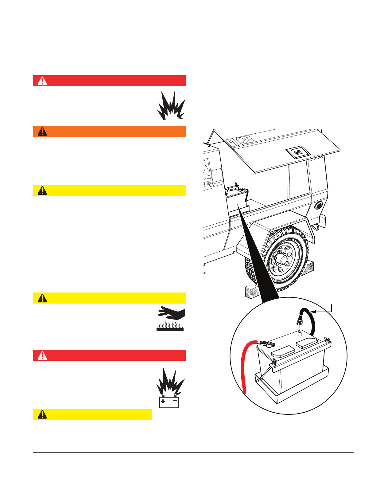
BATTERY DISCONNECTION
1. Open the battery-side cabinet door to access the
battery (Figure 2).
CABINET DOOR
Fuels, fluids, coolants, lubricants, and battery electrolyte
used in the air compressor are typical of the industry.
Care should be taken to avoid accidental ingestions and/
or skin contact.
Make sure the air pressure reads zero before performing
any maintenance.
ENGINE SAFETY
CAUTION
NEVER touch the hot exhaust manifold,
muffler or cylinder. Allow these parts to cool
before servicing the equipment.
BATTERY SAFETY
DANGER
DO NOT expose the battery to open flames,
sparks, cigarettes, etc. The battery contains
combustible gases and liquids. If these
gases or liquids come into contact with a
flame or spark, an explosion could occur.
NEGATIVE
(BLACK)
CAUTION
ALWAYS disconnect the NEGATIVE battery terminal
before performing service on the generator.
DIS185SSI4F AIR COMPRESSOR — HOSE REEL INSTALLATION INSTRUCTIONS P/N EE60468 — REV. #0 (04/16/18) — PAGE 3
Figure 2. Battery Cable Disconnection
2. Disconnect the negative cable (BLACK) from the
negative (−) terminal on the battery. See Figure 2.
Page 4
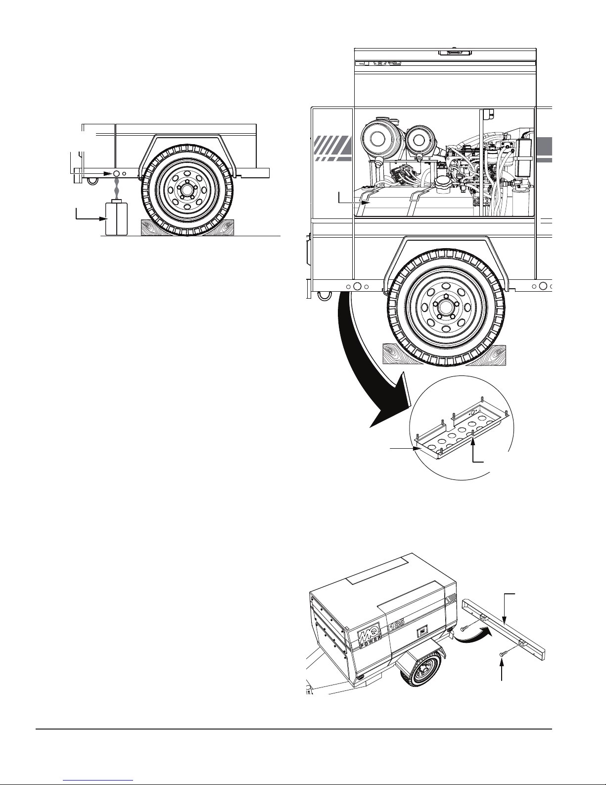
DRAINING THE FUEL TANK
If there is fuel in the fuel tank, it must be drained before
performing this installation.
1. Prepare a container (Figure 3) into which to drain the
fuel.
FUEL TANK
DRAIN BOLT
CONTAINER
Figure 3. Draining the Fuel Tank
2. The fuel drain bolt (Figure 3) is located on the fuel
tank side of the air compressor at the rear of the trailer
frame. Loosen the bolt to allow any fuel inside the tank
to drain into the container. Retighten the fuel drain bolt
when finished.
FUEL
TANK
NEW BUMPER INSTALLATION
1. The fuel tank base cover (Figure 4) must be loosened
to allow access to the bumper hardware. Loosen the
seven hex head bolts securing the fuel tank base
cover to the frame. DO NOT remove the bolts nor the
cover itself.
FUEL TANK
BASE COVER
Figure 4. Fuel Tank Base Cover
LOOSEN
BOLTS
2. Remove and discard the two hex head bolts securing
the existing rear bumper (Figure 5) to the chassis.
Discard the rear bumper.
REAR
BUMPER
DIS185SSI4F AIR COMPRESSOR — HOSE REEL INSTALLATION INSTRUCTIONS P/N EE60468 — REV. #0 (04/16/18) — PAGE 4
HEX HEAD BOLT
Figure 5. Rear Bumper Removal
Page 5
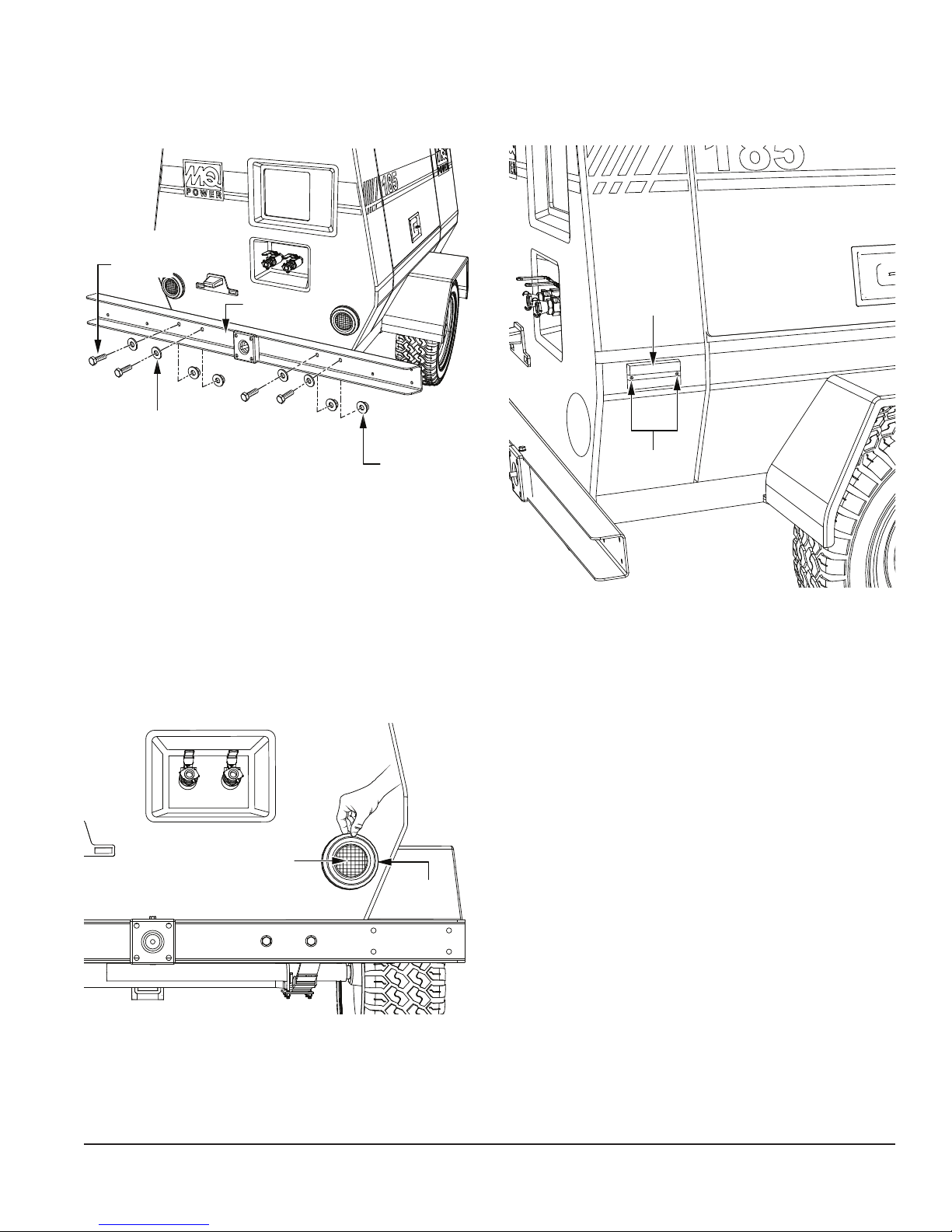
3. Secure the new bumper (P/N 59269) to the chassis
P/N 26328
with the four 1/2-13 × 1-1/2" hex head bolts (P/N 5218),
flat washers (P/N 0447), and 1/2"-13 flange nuts
(P/N 26328). See Figure 6.
1/2-13 × 1-1/2"
HEX HEAD BOLT
P/N 5218
BUMPER
P/N 59269
FLAT WASHER
P/N 0447
1/2"-13
FLANGE NUT
2. On the fuel tank side of the air compressor, remove
the two bolts securing the rear side marker lens
(Figure 8) to the frame. Set the lens and foam backing
aside and discard the bolts.
SIDE MARKER
LENS
REMOVE
TWO BOLTS
Figure 6. Bumper Installation
WIRING EXTENSION INSTALLATION
To install the wiring for this kit, the tail light on the fuel tank
side of the air compressor must be removed.
1. Remove by hand the rubber seal securing the tail light
(Figure 7) on the fuel tank side of the air compressor.
Disconnect the tail light and set it and the rubber seal
aside.
TAIL LIGHT
RUBBER
SEAL
Figure 8. Side Marker Lens Removal
Figure 7. Tail Light Removal
DIS185SSI4F AIR COMPRESSOR — HOSE REEL INSTALLATION INSTRUCTIONS P/N EE60468 — REV. #0 (04/16/18) — PAGE 5
Page 6

3. Cut the two wires extending from the side marker light
GREEN WIRE
bulb socket as shown in Figure 9. Set the light bulb
socket assembly aside for later.
5. The wiring extension harness (P/N 59291) contains
a red wire and a green wire. There are butt splice
connectors crimped onto each end of both wires. See
Figure 10.
EXTENSION
HARNESS
P/N 59291
STRIP
INSULATION 1/4"
CUT TWO
WIRES HERE
6"
SIDE MARKER
LIGHT BULB
BUTT SPLICE
CONNECTOR
RED WIRE
Figure 10. Wiring Extension Harness
6. Insert the end of one of the stripped wires into one
of the extension harness butt splice connectors
(Figure 11) and crimp.
STRIPPED
WIRES
BUTT SPLICE
CONNECTORS
EXTENSION
HARNESS
P/N 59291
SOCKET
Figure 9. Side Marker Light Disconnection
4. Strip the insulation back 1/4-inch (6 mm) from the end
of the remaining wires to expose the conductors. See
Figure 9.
DIS185SSI4F AIR COMPRESSOR — HOSE REEL INSTALLATION INSTRUCTIONS P/N EE60468 — REV. #0 (04/16/18) — PAGE 6
Figure 11. Wire Splicing
7. Insert the end of the other stripped wire into the
remaining butt splice connector on the same end of
the extension harness (P/N 59291) and crimp. See
Figure 11.
8. Push the spliced wiring extension harness (P/N 59291)
inside the cabinet through the side marker hole.
9. If installing the dual hose reel kit (P/N MQPDUALREEL50),
repeat steps #2–8 on the battery side of the air
compressor. DO NOT remove the battery-side
tail light! The battery-side electrical wiring can be
accessed by opening the cabinet door.
Page 7

BUMPER STOP INSTALLATION
PIVOT BASE INSTALLATION
1. On the fuel tank side of the air compressor, secure
the bumper stop (P/N 59267) to the frame where
the rear marker light was removed earlier with
two M4-0.7 × 12 mm screws (P/N 28922-083). See
Figure 12.
1. On the fuel tank side of the air compressor, drill a
3/4-inch hole into the side of the rear frame as shown
in Figure 13.
BUMPER STOP
P/N 59267
M4-0.7 × 12 mm
SCREW
P/N 28922-083
Figure 12. Bumper Stop Installation
2. If installing the dual hose reel kit (P/N MQPDUALREEL50),
repeat step #1 on the battery side of the air compressor.
REAR BUMPER
P/N 59269
1-3/4"
2-1/2"
Figure 13. Drill Wiring Harness Hole
DRILL HOLE
3/4" DIAMETER
DIS185SSI4F AIR COMPRESSOR — HOSE REEL INSTALLATION INSTRUCTIONS P/N EE60468 — REV. #0 (04/16/18) — PAGE 7
Page 8

1. Secure the pivot base plate (P/N 59234) to the end of
PIVOT BASE
P/N 59234
RIGHT
P/N 21781
the bumper (P/N 59269) with four 3/8-16 × 1-1/4" hex
flange bolts (P/N 1023) and four 3/8"-16 hex flange
nuts (P/N 21781). See Figure 14.
PLATE
BUMPER
P/N 59269
P/N 59234
FENDER
3/8"-16
HEX FLANGE NUT
P/N 21781
3/8-16 × 1-1/4"
HEX FLANGE BOLT
P/N 1023
PIVOT BASE
PLATE
3/8"-16
3/8-16 × 1-1/4"
HEX FLANGE BOLT
P/N 1023
HEX FLANGE NUT
P/N 21781
Figure 14. Pivot Base Plate Installation
2. Using the pivot base plate (P/N 59234) as a guide, drill
two 13/32-inch holes into the fender. See Figure 15.
FENDER
DRILL TWO
13/32" HOLES
PIVOT BASE
PLATE
P/N 59234
Figure 16. Secure Pivot Base Plate to Fender
4. Secure the right pivot base (P/N 59272) to the pivot
base plate (P/N 59234) with two 3/8-16 × 1-1/4" hex
flange bolts (P/N 1023) and two 3/8"-16 hex flange
nuts (P/N 21781). Place pivot plate shims (P/N 59286)
between the pivot base plate and pivot base as needed
to keep the top of the base level with the top of the
fender. See Figure 17.
PIVOT BASE
P/N 59272
3/8-16 × 1-1/4"
HEX FLANGE BOLT
P/N 1023
SHIM
P/N 59286
Figure 15. Drill Pivot Base Plate Holes
3. Insert two 3/8-16 × 1-1/4" hex flange bolts (P/N 1023)
through the new holes in the fender with two 3/8"-16
hex flange nuts (P/N 21781), and tighten securely.
See Figure 16.
DIS185SSI4F AIR COMPRESSOR — HOSE REEL INSTALLATION INSTRUCTIONS P/N EE60468 — REV. #0 (04/16/18) — PAGE 8
3/8"-16 HEX
FLANGE NUT
PIVOT BASE
PLATE
P/N 59234
Figure 17. Pivot Base Installation
Page 9

5. Using the pivot base (P/N 59272) as a guide, drill two
13/32-inch holes into the top of the fender as shown
in Figure 18.
FENDER
PIVOT BASE
P/N 59272
DRILL TWO
13/32" HOLES
SIDE MARKER INSTALLATION
1. Strip the insulation back 1/4-inch (6 mm) from the
ends of the wires extending from the back of the side
marker light bulb socket to expose the conductors.
See Figure 20.
SIDE MARKER
STRIP
INSULATION 1/4"
SOCKET
LIGHT BULB
Figure 18. Drill Pivot Base Holes
6. Insert two 3/8-16 × 1-1/4" hex flange bolts (P/N 1023)
through the new holes in the fender with two 3/8"-16
hex flange nuts (P/N 21781), and tighten securely.
See Figure 19.
3/8-16 × 1-1/4"
HEX FLANGE BOLT
P/N 1023
FENDER
3/8"-16 HEX
FLANGE NUT
P/N 21781
Figure 20. Strip Side Marker Wires
Figure 19. Secure Pivot Base to Fender
7. If installing the dual hose reel kit (P/N MQPDUALREEL50),
repeat steps #1–6 with the left pivot base (P/N 59273)
on the battery side of the air compressor.
DIS185SSI4F AIR COMPRESSOR — HOSE REEL INSTALLATION INSTRUCTIONS P/N EE60468 — REV. #0 (04/16/18) — PAGE 9
Page 10

2. From inside the frame, insert the spliced wiring
PIVOT BASE
P/N 28922-083
RIGHT REEL
extension harness (P/N 59291) through the newly
drilled 3/4-inch hole in the frame so that it extends out
of the pivot base plate hole as shown in Figure 21.
SIDE MARKER
LIGHT BULB
PLATE
P/N 59234
FOAM
BACKING
EXTENSION
HARNESS
P/N 59291
PIVOT BASE
PLATE
SIDE MARKER
BUTT SPLICE
CONNECTORS
LIGHT
Figure 21. Side Marker Wiring Connection
3. Insert the stripped end of one of the side marker wires
into one of the extension harness butt splice connectors
(Figure 21) and crimp.
4. Insert the stripped end of the remaining side marker
wire into the remaining extension harness butt splice
connector (Figure 21) and crimp.
5. Place the side marker light bulb socket into the
hole in the pivot base plate (P/N 59234). Secure
the side marker lens and foam backing to the
pivot base plate with two M4-0.7 × 12 mm screws
(P/N 28922-083) and two M4 hex nuts (P/N 32664)
See Figure 22.
M4 HEX NUT
P/N 32664
SIDE MARKER
LENS
M4-0.7 × 12 mm
SCREW
Figure 22. Side Marker Installation
6. Reinstall the tail light and rubber seal on the fuel tank
side of the air compressor.
7. If installing the dual hose reel kit (P/N MQPDUALREEL50),
repeat steps #1–5 on the battery side of the air
compressor.
HOSE REEL INSTALLATION
1. Insert the right reel mount (P/N 59275) into the pivot
base (P/N 59272) as shown in Figure 23.
MOUNT
P/N 59275
PIVOT BASE
P/N 59272
DIS185SSI4F AIR COMPRESSOR — HOSE REEL INSTALLATION INSTRUCTIONS P/N EE60468 — REV. #0 (04/16/18) — PAGE 10
Figure 23. Reel Mount Installation
Page 11

2. Secure the right reel mount (P/N 59275) to the
pivot base (P/N 59272) with the slotted hex nut
(P/N EM968481) and 3/16 × 2" cotter pin (P/N 38709)
as shown in Figure 24. Bend the cotter pin tines to
lock it in place.
RIGHT REEL
MOUNT
P/N 59275
PIVOT BASE
P/N 59272
MARK AND DRILL
TWO 11/32" HOLES
ALIGN PIN
WITH HOLE
IN REEL
MOUNT
FENDER
9/16"
REEL MOUNT
LOCK LATCH
P/N 59251
RIGHT
REEL MOUNT
P/N 59275
SLOTTED
HEX NUT
P/N EM968481
COTTER PIN
P/N 38709
Figure 24. Secure Reel Mount to Pivot Base
3. Place the reel mount lock latch (P/N 59251) onto the
fender 9/16-inch from the end of the right reel mount
(P/N 59275). Align the pin in the center of the reel
mount lock latch with the hole in the reel mount. See
Figure 25.
Figure 25. Drill Reel Mount Lock Latch Holes
4. Make sure the reel mount (P/N 59275) swings out freely
without hitting the reel mount lock latch (P/N 59251),
then mark the two lock latch hole positions on the right
fender with a scriber or equivalent tool. See Figure 25.
5. Drill two 11/32-inch holes into the top of the fender
(Figure 25).
DIS185SSI4F AIR COMPRESSOR — HOSE REEL INSTALLATION INSTRUCTIONS P/N EE60468 — REV. #0 (04/16/18) — PAGE 11
Page 12

6. Secure the reel mount lock latch (P/N 59251) to
5/16-18 × 3/4"
the fender with the two 5/16-18 × 3/4" hex flange
bolts (P/N 36720) and two 5/16"-18 hex flange nuts
(P/N 49071). Place lock latch shims (P/N 59289)
between the reel mount lock latch and fender as
needed to keep the lock latch pin lined up with the hole
in the right reel mount (P/N 59275). See Figure 26.
8. If installing the dual hose reel kit (P/N MQPDUALREEL50),
repeat steps #1–7 with the left reel mount (P/N 59276)
on the battery side of the unit.
9. Each hose reel (P/N 59263) includes a 3/4" swivel
fitting. On the fuel tank side of the air compressor,
place 1/2" thread sealant tape onto the male threads
of the hose reel swivel fitting. See Figure 28.
HEX FLANGE BOLT
P/N 36720
FENDER
5/16"-18 HEX
FLANGE NUT
P/N 49071
REEL MOUNT
LOCK LATCH
P/N 59251
LOCK
LATCH SHIM
P/N 59289
Figure 26. Reel Mount Lock Latch Installation
7. Secure the hose reel (P/N 59263) to the right reel
mount (P/N 59275) with four 3/8-16 × 1-1/4" hex flange
bolts (P/N 1023) and four 3/8"-16 hex flange nuts
(P/N 21781). See Figure 27.
FUEL TANK
SIDE
PLACE 1/2" THREAD
SEALANT TAPE
ON MALE THREADS
HOSE REEL
P/N 59263
SWIVEL
FITTING
Figure 28. Swivel Fitting Installation
(Fuel Tank Side)
3/8-16 × 1-1/4"
HEX FLANGE BOLT
P/N 1023
3/8"-16
HEX FLANGE NUT
P/N 21781
Figure 27. Hose Reel Installation
RIGHT REEL
MOUNT
P/N 59275
HOSE REEL
P/N 59263
10. Insert the swivel fitting into the opening on the hose
reel (P/N 59263) on the fuel tank side of the air
compressor, and tighten it securely (Figure 28).
DIS185SSI4F AIR COMPRESSOR — HOSE REEL INSTALLATION INSTRUCTIONS P/N EE60468 — REV. #0 (04/16/18) — PAGE 12
Page 13

11. If installing the dual hose reel kit (P/N MQPDUALREEL50),
remove the hex plug on the hose reel (P/N 59263) on
the battery side of the air compressor. See Figure 29.
HEX PLUG
13. Place 1/2" thread sealant tape onto the threads of the
battery-side hose reel swivel fitting (Figure 31). Insert
the swivel fitting into the opening on the battery-side
hose reel (P/N 59263) and tighten it securely.
PLACE 1/2" THREAD
SEALANT TAPE
ON MALE THREADS
HOSE REEL
P/N 59263
BATTERY
SIDE
Figure 29. Hex Plug Removal (Battery Side)
12. Place 1/2" thread sealant tape onto the threads of
the hex plug (Figure 30). Insert the hex plug into the
opening on the opposite side of the battery-side hose
reel (P/N 59263), and tighten it securely.
PLACE 1/2" THREAD
SEALANT TAPE
ON THREADS
HOSE REEL
P/N 59263
SWIVEL
FITTING
HOSE REEL
P/N 59263
Figure 31. Swivel Fitting Installation
(Battery Side)
BATTERY
SIDE
Figure 30. Hex Plug Installation
(Battery Side)
DIS185SSI4F AIR COMPRESSOR — HOSE REEL INSTALLATION INSTRUCTIONS P/N EE60468 — REV. #0 (04/16/18) — PAGE 13
HEX PLUG
BATTERY
SIDE
Page 14

HOSE INSTALLATION
RIGHT AIR
1. Place 1/2" thread sealant tape onto the straight fitting
on the hose (P/N 59265). See Figure 32.
PLACE 1/2" THREAD
SEALANT TAPE
ON STRAIGHT FITTING
HOSE REEL
P/N 59263
4. Loop the other end of the safety cable (P/N 59274)
onto the 90-degree fitting end of the hose (P/N 59265).
See Figure 33.
5. Connect the 90-degree fitting on the hose (P/N 59265)
to the right air output valve at the rear of the air
compressor. See Figure 33.
6. If installing the dual hose reel kit (P/N MQPDUALREEL50),
repeat steps #1–5 on the battery side of the unit.
JACK INSTALLATION
Secure the jack (P/N 29479) to the bumper (P/N 59269)
with the included lock nut and spacer. See Figure 34.
BUMPER
P/N 59269
HOSE
P/N 59265
SWIVEL
FITTING
FUEL TANK
SIDE
Figure 32. Connect Hose to Reel
2. On the fuel tank side of the air compressor, connect
the straight fitting on the hose (P/N 59265) to the
swivel fitting on the hose reel (P/N 59263), and tighten
securely. See Figure 32.
3. Loop one end of the safety cable (P/N 59274) onto the
right air output valve at the rear of the air compressor.
See Figure 33.
OUTPUT VALVE
JACK
P/N 29479
SPACER
LOCK NUT
Figure 34. Jack Installation
SAFETY CABLE
P/N 59274
P/N 59265
Figure 33. Connect Hose to Output Valve
DIS185SSI4F AIR COMPRESSOR — HOSE REEL INSTALLATION INSTRUCTIONS P/N EE60468 — REV. #0 (04/16/18) — PAGE 14
90º FITTING
HOSE
Page 15

BALLAST INSTALLATION
1. To open the storage compartment at the front of the
air compressor, turn the storage compartment door
thumb screws counterclockwise and open the door
(Figure 35).
M8 × 40 mm
BOLT
P/N 42346
TOOL TRAY
TOOL TRAY
DISCARD
BOLTS
RETAIN
WASHERS
STORAGE
COMPARTMENT
DOOR
THUMB
SCREWS (2)
Figure 35. Tool Tray Removal
2. Remove the four bolts, lock washers, and flat washers
securing the tool tray inside the storage compartment
(Figure 35). Set the tool tray and washers aside, and
discard the bolts.
EXISTING
BALLAST
PLATE
P/N 59290
Figure 36. Ballast Plate Installation
EXISTING
WASHER
LOCK
WASHER
FLAT
4. Place the tool tray on top of the ballast plates
(P/N 59290), and secure the tray and plates to the
inside of the storage compartment with the four
M8 × 40 mm bolts (P/N 42346) and the four lock
washers and flat washers that were removed earlier.
See Figure 36.
POST INSTALLATION
1. Tighten the seven hex head bolts securing the fuel tank
base cover to the frame.
2. Make sure all fasteners are tightened securely.
3. Reconnect the negative cable (BLACK) to the negative
(−) terminal on the battery.
3. If installing the single hose reel kit
4. Refill the fuel tank with diesel fuel.
(P/N MQPSINGLEREEL50), place two ballast plates
(P/N 59290) inside the storage compartment as
shown in Figure 36. If installing the dual hose reel kit
(P/N MQPDUALREEL50), place three ballast plates
inside the storage compartment.
DIS185SSI4F AIR COMPRESSOR — HOSE REEL INSTALLATION INSTRUCTIONS P/N EE60468 — REV. #0 (04/16/18) — PAGE 15
Page 16

HERE’S HOW TO GET HELP
© COPYRIGHT 2017, MULTIQUIP INC.
Multiquip Inc
the MQ logo are registered trademarks of Multiquip Inc. and may not be used, reproduced, or altered without written permission. All other trademarks are the property
of their respective owners and used with permission.
The information and specifi cations included in this publication were in effect at the time of approval for printing. Illustrations, descriptions, references and technical data contained in
this document are for guidance only and may not be considered as binding. Multiquip Inc. reserves the right to discontinue or change specifi cations, design or the information published
in this publication at any time without notice and without incurring any obligations.
DIS185SSI4F Air Compressor
Hose Reel Kit Installation Instructions
PLEASE HAVE THE MODEL AND SERIAL
NUMBER ON-HAND WHEN CALLING
UNITED STATES
Multiquip Corporate Offi ce MQ Parts Department
18910 Wilmington Ave.
Carson, CA 90746
Contact : mq@multiquip.com
Service Department Warranty Department
800-421-1244
310-537-3700
Technical Assistance
800-478-1244 Fax: 310-943-2238
CANADA
Multiquip Multiquip (UK) Limited Head Offi ce
4110 Industriel Boul.
Laval, Quebec, Canada H7L 6V3
Contact : infocanada@multiquip.com
Tel. (800) 421-1244
Fax (310) 537-3927
Tel: (450) 625-2244
Tel: (877) 963-4411
Fax: (450) 625-8664
800-427-1244
310-537-3700
800-421-1244
310-537-3700
UNITED KINGDOM
Unit 2, Northpoint Industrial Estate,
Globe Lane,
Dukinfi eld, Cheshire SK16 4UJ
Contact : sales@multiquip.co.uk
Fax: 800-672-7877
Fax: 310-943-2249
Tel: 0161 339 2223
Fax: 0161 339 3226
and
Your Local Dealer is:
 Loading...