

Page 1

)
OPERATION AND PARTS MANUAL
Electric, Gasoline and Propane Converted
Electric and Gasoline
Crack Saw
Model CS8 Series
Surface Grinders
Model DFG Series
Revision #4(05/28/09
THIS MANUAL MUST ACCOMPANY THE EQUIPMENT AT ALL TIMES
To find the latest revision of this
publication, visit our website at:
www.multiquip.com
Page 2

Page 3

TABLE OF CONTENTS
MULTIQUIP DFG SERIES SURFACE GRINDERS
Table Of Contents................................................................................................................................. 3-4
Parts Ordering Procedures ................................................................................................................... 6
Notice to Operators............................................................................................................................... 7-8
Operator Instructional Data Sheet ........................................................................................................ 9
Safety Precautions................................................................................................................................ 10
Preparation ........................................................................................................................................10-11
Operation ........................................................................................................................................... 12-13
Maintenance, Repair and Storage..................................................................................................... 13-14
Assembly .............................................................................................................................................. 15
Removing the SURFACE GRINDER from the Pallet ........................................................................15
Installing the SSG24-1000 Safety and Dust Shield Assembly Kit..................................................... 16
Before Starting the Engine.................................................................................................................... 17
Filling the Engine Crankcase with Oil ................................................................................................ 17
Filling the DFG/G Series Engine Fuel Tank ......................................................................................17
Assembly Instructions/Operation.......................................................................................................... 18
Theory of Operation........................................................................................................................... 18
Multi-Accessory Attachments and Applications................................................................................. 19-26
Installing a Multi-Accessory Attachment (not including multi-segmented, dry diamond discs)
in the counter-rotating discs............................................................................................................... 26-27
Removing a Multi-Accessory Attachment (not including multi-segmented, dry diamond discs)
from the counter-rotating discs .......................................................................................................... 28-29
Transporting the Surface Grinder ...................................................................................................... 29
Adjusting the Operator Handle Height............................................................................................... 30
Starting the DFG/E Series Electrically Powered Surface Grinder On the Job Site ........................... 30-32
Starting the DFG/G Series Gasoline Powered Surface Grinder On the Job Site ............................. 32-33
Operating the Surface Grinder on the Job Site .................................................................................33-36
Stopping the DFG/E Electrically Powered Surface Grinder ..............................................................36
Stopping the DFG/G Gasoline Powered Surface Grinder ................................................................. 36
Operational Parameters and Techniques for DFG Series Surface Grinder’s ...................................36-39
DFG-SERIES SURFACE GRINDERS OPERATION AND PARTS MANUAL REV. #4 (05/28/09) PAGE 3
Page 4

Maintenance/Service ............................................................................................................................40
Preventative Maintenance Check List ............................................................................................... 40
Checking V-Belt Tension and Alignment ........................................................................................... 40
Installing a Replacement V-Belt or Centrifugal Clutch or Pulley .......................................................41-43
Replacing the LORD® Type Elastomeric Mounts on the Multi-Accessory Discs.............................. 44
Lubrication Requirements.................................................................................................................. 45
Electric Motor Service........................................................................................................................ 46
Engine Service................................................................................................................................... 46
Troubleshooting .................................................................................................................................... 47
Electric Motor..................................................................................................................................... 47
Gasoline Engine.................................................................................................................................... 47-48
Storage ................................................................................................................................................. 49
Specifications........................................................................................................................................ 50
Explanation of Code In Remarks Column ............................................................................................ 52
Suggested Spare Parts......................................................................................................................... 53
Component Parts Drawings
Operator Handle Assembly (Electric) ................................................................................................ 54-55
Operator Handle Assembly (Gasoline).............................................................................................. 56-57
Electric Motor Assembly .................................................................................................................... 58-59
Gasoline Engine Assembly................................................................................................................ 60-61
Wheel Assembly ................................................................................................................................ 62-63
Transmission Assembly..................................................................................................................... 64-65
Head Assembly.................................................................................................................................. 66-67
Safety and Shield Assembly.............................................................................................................. 68-69
Scarifier Assembly ............................................................................................................................. 70-71
SCRAPE-R-TACH ............................................................................................................................. 72-73
Grinder Block Assembly .................................................................................................................... 74-75
Decals ................................................................................................................................................ 76-77
Terms and Condition of Sale —Parts ................................................................................................ 78
TABLE OF CONTENTS
DFG-SERIES SURFACE GRINDERS OPERATION AND PARTS MANUAL REV. #4 (05/28/09) PAGE 4
Page 5

NOTE PAGE
DFG-SERIES SURFACE GRINDERS OPERATION AND PARTS MANUAL REV. #4 (05/28/09) PAGE 5
Page 6

www.multiquip.com
PARTS ORDERING PROCEDURES
Ordering parts has never been easier!
Best Deal!
Order via Internet
Order parts on-line using Multiquip’s SmartEquip website!
■ View Parts Diagrams
■ Order Parts
■ Print Specifi cation Information
Goto www.multiquip.com and click on
Order Parts
Choose from three easy options:
(Dealers Only)
to log in and save!
:
Use the internet and qualify for a 5% Discount
on Standard orders for all orders which include
complete part numbers.*
If you have an MQ Account, to obtain a Username
and Password, E-mail us at: parts@multiquip.
com.
To obt a in a n MQ Account, contact you r
District Sales Manager for more information.
Effective:
st
January 1
Note: Discounts Are Subject To Change
, 2006
Order via Fax
All customers are welcome to order parts via Fax.
Domestic (US) Customers dial:
1-800-6-PARTS-7 (800-672-7877)
(Dealers Only)
:
Fax your order in and qualify for a 2% Discount
on Standard orders for all orders which include
complete part numbers.*
Note: Discounts Are Subject To Change
Order via Phone:
Domestic (US) Dealers Call:
1-800-427-1244
Non-Dealer Customers:
Contact your local Multiquip Dealer for
parts or call 800-427-1244 for help in
locating a dealer near you.
When ordering parts, please supply:
❒ Dealer Account Number
❒ Dealer Name and Address
❒ Shipping Address (if different than billing address)
❒ Return Fax Number
❒ Applicable Model Number
❒ Quantity, Part Number and Description of Each Part
NOTICE
All orders are treated as Standard Orders and will
ship the same day if received prior to 3PM PST.
International Customers should contact
their local Multiquip Representatives for
Parts Ordering information.
❒ Specify Preferred Method of Shipment:
✓ UPS/Fed Ex ✓ DHL
■ Priority One ✓ Tr uck
■ Ground
■ Next Day
■ Second/Third Day
WE ACCEPT ALL MAJOR CREDIT CARDS!
DFG-SERIES SURFACE GRINDERS OPERATION AND PARTS MANUAL REV. #4 (05/28/09) PAGE 6
Page 7

IF YOU CAN NOT READ OR DO NOT FULLY UNDERSTAND THE CONTENTS OF THIS
MANUAL, PLEASE CONTACT THE FACTORY FOR PROPER ASSISTANCE BEFORE
ATTEMPTING TO OPERATE THIS PRODUCT.
SI TU NO PUEDES LE'ER O NO COMPRENDES EL CONTENIDO DE ESTE MANUAL
FAVOR DE PONERSE EN CONTACTO CON LA. FABRICA PARA ASSISTENCIA- A
PROPIA ANTES DE INTENTAR PARA OPERAR ESTE PRODUCTO.
SOLLTEN SIE DIESE GEBRAUCHSANWEISUNG NICHT LESEN KOENNEN ODER ES
NICHT VOLLKOMMEN VERSTEHEN, WENDEN SIE SICH BITTE AN DEN HERSTELLER
FUER RICHTIGE HILFE EHE SIE VERSUCHEN DIESES PRODUKT ZU OPERIEREN.
SI VOUS NE LISEZ OU NE COMPRENDRE ENTIEREMENT LES MATIERES DE CE
MANUEL, S'IL VOUS PLAIT, CONTACTEZ L'USINE POUR L'ASSISTANCE APPROPRIEE
AVANT D'UTILISER LE PRODUIT.
NOTICE TO OPERATORS
DANGER
CAUTION
These safety alert symbols identify important safety messages in this manual. When you see these symbols, be
alert to the possibility of personal injury and carefully read the message that follows.
Do not allow anyone to operate the SURFACE GRINDER without first reading this Operator Manual and
becoming familiar with its operation. The manufacturer of the SURFACE GRINDER has gone to great extremes to
provide the owner(s) and/or operator(s) with the finest equipment available for its intended job function of
removing covering materials from concrete and wood floor surfaces. Yet, the possibility exists that the SURFACE
GRINDER can be utilized in and/or subjected to job applications not perceived and/or anticipated by the
nufacturer. Such misuse and/or misapplication of the SURFACE GRINDER can lead to the possibility of
ma
serious damage, injury or even death. It is the responsibility of the owner(s) and/or operator(s) to determine that
the SURFACE GRINDER is being utilized and/or operated within the scope of its intended job function. It is the
responsibility of the owner(s) and/or operator(s) to establish, monitor and constantly upgrade all safety programs
and/or practices utilized in and for the operation of the SURFACE GRINDER. The purpose of such programs is to
provide for owner(s') and/or operator(s') safety. Operators must be instructed to recognize and avoid unsafe
conditions associated with their work (29 CFR 1926.21 (b)(2)) and/or applicable updated revisions. It is the
responsibility of the owner(s) and/or operator(s) to determine that no modifications a
made to the SURFACE GRINDER. Modifications and/or alterations can lead to the possibility of serious damage,
injury or even death. It is the responsibility of the owner(s) and/or operator(s) to make this Operator Manual
available for consultation during all phases of operation. Refer to OSHA 2207 and/or applicable updated revisions
which contains all OSHA job safety and health rules and regulations (1926 and 1910) covering construction.
nd/or alterations have been
DFG-SERIES SURFACE GRINDERS OPERATION AND PARTS MANUAL REV. #4 (05/28/09) PAGE 7
Page 8

CAUTION
The concept of powered SURFACE GRINDER has been successfully utilized for many years as a practical
solution to many types of surface preparation requirements. The basic concept is proven and well
accepted within the associated marketplaces. Use of a SURFACE GRINDER requires strenuous work
activity. This type of work activity can be considered to be greater in magnitude than that experienced
with the use of many other types of both light construction and lawn and garden related equipment. This
type of work activity should only be attempted by operators of adequate physical size and stature, mental
awareness and physical strength and condition. The body parts most noticeably affected during any
specific process are the arms, hands, wrists, shoulders, lower back and legs. The process can also
produce excessive stress/strain directly to the back muscles, spinal vertebrae and many other body
parts. Back related pain can be a side effect of utilizing a SURFACE GRINDER. An operator with a chronic
back related problem or a history of back and/or other medically related problems should not attempt to
utilize the SURFACE GRINDER. Use of the SURFACE GRINDER may only aggravate this and any other
medically related problem. Because of the diverse type of prevailing job applications, job site conditions,
operator experience levels and operator physical characteristics, no warranty, guarantee, representation
and/or liability is made by the manufacturer as to the absolute correctness or sufficiency of any
operational procedure, operational position and/or technique. There is no absolute guarantee that an
operator of any given experience level, physical size and/or physical condition will be immune to the
possibility of and/or probable physical side effects of the normal use of the SURFACE GRINDER. Each
potential operator must be made aware of and assume the operational and physical liability described
and/or associated with the use of the SURFACE GRINDER. Improper use of the SURFACE GRINDER can
result in property damage and/or personal injury, including death. Each potential operator not willing to
assume the operational and physical liability described and/or associated with the use of the SURFACE
GRINDER, should not operate it. Proper levels of operator experience, skill and common sense are
essential for maximizing the safe and efficient operation of the SURFACE GRINDER.
Record the SURFACE GRINDER and electric motor serial numbers in the spaces provided below.
_______________ Model Number
_______________ Serial Number
_______________ Electric Motor Serial Number
_______________ Date of Purchase
Specifications and design are subject to change without notice or obligation. All specifications are general in
nature and are not intended for specific application purposes. Multiquip, Inc. reserves the right to make changes
in design, engineering or specifications and to add improvements or discontinue manufacture at any time without
notice or obligation. Multiquip, Inc. and its agents accept no responsibility for variations which maybe evident in
actual products, specifications, pictures and descriptions contained in this publication.
NOTICE TO OPERATORS
DFG-SERIES SURFACE GRINDERS OPERATION AND PARTS MANUAL REV. #4 (05/28/09) PAGE 8
Page 9

The following undersigned operators of the SURFACE GRINDER described and/or pertaining to this Operator
Manual have received formal safety and operational information/instruction from the undersigned
owner(s)/instructor(s) in accordance to OSHA 29 CFR 1926.21 (b)(2) and/or applicable updated revisions
pertaining to, but not necessarily limited to the:
1) READING, COMPREHENSION AND ACKNOWLEDGEMENT OF THE MATERIAL COMPRISING THE
ENTIRE CONTENTS OF THE APPLICABLE OPERATOR MANUAL AND APPLICABLE SAFETY AND
OPERATIONAL INFORMATION VIDEO TAPE FOR THE SURFACE GRINDER.
2) FORMALIZED OPERATOR SAFETY PROGRAM TO BE DEVISED BY THE OWNER OF THE SURFACE
GRINDER IN CONJUNCTION WITH THE CONTENTS OF THE APPLICABLE OPERATOR MANUAL AND
THE APPLICABLE SAFETY AND OPERATIONAL INFORMATION VIDEO TAPE FOR THE SURFACE
GRINDER AND THE APPLICABLE MATERIAL INCLUDED IN THE NATIONAL ELECTRICAL CODE®.
3) OSHA AND NATIONAL ELECTRIC CODE® RULES AND REGULATIONS RESEARCHED FOR AND/OR
BY THE OWNER OF THE SURFACE GRINDER AND DEEMED APPLICABLE TO THE SAFE AND
PROPER USE AND/OR OPERATION OF THE SURFACE GRINDER FOR ANY SPECIFIC JOB
APPLICATION.
4) LOCAL LAWS, REGULATIONS AND CUSTOMS RESEARCHED FOR AND/OR BY THE OWNER OF THE
SURFACE GRINDER AND DEEMED APPLICABLE TO THE SAFE AND PROPER USE AND/OR
OPERATION OF THE SURFACE GRINDER FOR ANY SPECIFIC JOB APPLICATION.
5) FORMALIZED MAINTENANCE PROGRAM FOR THE SURFACE GRINDER TO BE DEVISED BY THE
OWNER OF THE SURFACE GRINDER IN ACCORDANCE WITH, BUT NOT NECESSARILY LIMITED TO,
THE SPECIFICATIONS, GUIDELINES AND OPERATIONAL INFORMATION CONTAINED IN THE
APPLICABLE OPERATOR MANUAL.
OPERATOR INSTRUCTIONAL DATA SHEET
6) COMPREHENSIVE OPERATIONAL INSTRUCTIONS FOR THE CORRECT AND PROPER USE OF THE
SURFACE GRINDER AS PER THE CONTENTS OF THE APPLICABLE OPERATOR'S MANUAL, SAFETY
AND OPERATIONAL INFORMATION VIDEO TAPE AND APPLICABLE MATERIAL INCLUDED IN THE
NATIONAL ELECTRIC CODE®.
_______________ Operator _______________ Owner/Instructor __________ Date
_______________ Operator _______________ Owner/Instructor __________ Date
_______________ Operator _______________ Owner/Instructor __________ Date
_______________ Operator _______________ Owner/Instructor __________ Date
_______________ Operator _______________ Owner/Instructor __________ Date
_______________ Operator _______________ Owner/Instructor __________ Date
NOTE: INSERT COPIES OF THIS PAGE WITHIN THE OPERATOR'S MANUAL IF SPACE FOR ADDITIONAL
OPERATORS IS REQUIRED.
DFG-SERIES SURFACE GRINDERS OPERATION AND PARTS MANUAL REV. #4 (05/28/09) PAGE 9
Page 10

SAFETY PRECAUTIONS
THE FOLLOWING SAFETY PRECAUTIONS
PROVIDE SOME COMMON SENSE GUIDES TO
PROMOTE SAFETY AND EFFICIENCY WITH THE
SURFACE GRINDER. NO WARRANTY,
GUARANTEE OR REPRESENTATION IS MADE
BY THE MANUFACTURER AS TO THE
ABSOLUTE CORRECTNESS OR SUFFICIENCY
OF ANY INFORMATION OR STATEMENT. THESE
SAFETY PRECAUTIONS ARE INTENDED TO
DEAL PRINCIPALLY WITH COMMON
PRACTICES AND CONDITIONS ENCOUNTERED
IN THE USE OF THE SURFACE GRINDER AND
ARE NOT INTENDED TO BE ALL INCLUSIVE.
PROPER LEVELS OF OPERATOR EXPERIENCE,
SKILL AND COMMON SENSE ARE ESSENTIAL
FOR SAFE AND EFFICIENT OPERATION.
THE ENGINE EXHAUST FROM THIS PRODUCT
CONTAINS CHEMICALS KNOWN TO THE STATE
OF CALIFORNIA TO CAUSE CANCER, BIRTH
DEFECTS OR OTHER REPRODUCTIVE HARM.
THIS STATEMENT IS MADE IN COMPLIANCE TO
CALIFORNIA PROPOSITION 65.
DANGER
DANGER
DANGER
INCORRECT USE OF THE SURFACE GRINDER
CAN RESULT IN PROPERTY DAMAGE,
PERSONAL INJURY OR EVEN DEATH. TO
REDUCE THIS POSSIBILITY, GIVE COMPLETE
AND UNDIVIDED ATTENTION TO THE JOB AT
HAND AND FOLLOW THESE SAFETY
PRECAUTIONS:
PREPARATION.
1) This SURFACE GRINDER is specialized type of
powered equipment, designed for a specific job
function and requires adequate and thorough
instruction BEFORE it is operated. The size,
power, complexity and operating characteristics
of this type of powered equipment would dictate
that each operator must receive adequate,
professional instruction regarding the proper
operation of this SURFACE GRINDER before
being allowed to utilize it. BEFORE attempting to
utilize this SURFACE GRINDER, read this
Operator's Manual, the applicable Safety and
Operating Information Video Tape and the
material supplied by the engine manufacturer to
fa
miliarize each operator with its correct
operating procedures. Avoid the urge not to take
the necessary time to read this Operator's
Manual before operating the SURFACE
GRINDER. DO NOT OPERATE THE SURFACE
GRINDER UNTIL EACH OPERATOR
COMPLETELY COMPREHENDS THE
CONTENTS OF THIS MANUAL AND THE
APPLICABLE SAFETY AND OPERATIONAL
INFORMATION VIDEO TAPE.
2) Develop a comprehensive program for the safe
operation of the SURFACE GRINDER by its
owner(s) and/or operator(s). Such a program will
include, but is not limited to: instructional
requirements for operation, applicable OSHA
requirements, local laws and regulations, job site
safety and a SURFACE GRINDER maintenance
program. Constantly examine and upgrade this
program to guara
operator(s) safety. Each operator must be fully
instructed regarding the specifics of this safety
program.
3) Determine that the SURFACE GRINDER is in its
original, factory configuration and has not been
modified in any manner. Many modifications can
result in potentially dangerous configurations
that can lead to property damage and/or
personal injury. If there are any questions about
possible modifications made to the SURFACE
GRINDER, contact the Customer Service
Department for specific information BEFORE
utilization. There is no charge for this service.
Do not operate the SURFACE GRINDER
without the use of the original equipment V-belt
ard. Use of the SURFACE GRINDER without
gu
an approved belt guard can lead to property
damage and/or personal injury.
4) Minors should never be allowed to operate the
SURFACE GRINDER. Bystanders, especially
children and animals, should not be allowed in
the area where the SURFACE GRINDER is in
use. The grinding process can result in flying
particles being emitted at high velocity and
striking the operator and/or onlookers. This can
lead to the possibility of property damage and/or
personal injury. Keep all body parts, loose
clothing, foreign objects and onlookers clear of
the rotating discs, multi-accessory attachments
and flying particles.
5) Oper
ators must be in adequate physical
condition, mental health and not under the
influence of any substance (drugs, alcohol, etc.)
which might impair vision, dexterity or judgment.
Working with the SURFACE GRINDER is
strenuous. If you have any condition that might
be aggravated by strenuous work, check with
your doctor BEFORE operating the SURFACE
ntee owner(s) and/or
DFG-SERIES SURFACE GRINDERS OPERATION AND PARTS MANUAL REV #4 (05/28/09) PAGE 10
Page 11

SAFETY PRECAUTIONS
GRINDER. Guide against the possibility of back
related injuries. Always lift the SURFACE
GRINDER with leg muscles and not with the
back.
6) Prolonged use of the SURFACE GRINDER (or
other, similar machines) exposes the operator to
vibrations which may produce Whitefinger
Disease (Raynaud's Phenomenon). This
phenomenon reduces the hand's ability to feel
and regulate temperature, produces numbness
and burning sensations and may cause nerve
and circulation damage and tissue necrosis.
Anti-vibration systems do not guarantee that you
will not sustain Whitefinger Disease. Therefore,
continuous and regular users should closely
monitor the condition of their hands and fingers.
After each period of use, exercise to restore
normal blood circul
appear, seek medical advice immediately.
7) Clothing must be sturdy and snug fitting, but
allow complete freedom of movement. Never
wear loose fitting jackets, scarves, neckties,
jewelry, flared or cuffed pants or anything that
could become caught on controls or moving
parts. Wear long pants to protect your legs.
Protect your hands with heavy duty, non-slip
gloves to improve your grip. Good footing is
most important when operating the SURFACE
GRINDER. Wear sturdy boots with non-slip
soles. Steel-toed safety shoes are highly
recommended. Never wear tennis shoes or
other, similar type shoes which afford little or no
protection. Wear an approved safety hard hat to
protect the operator'(s') head(s) where there is a
danger of head injuries. Noise, generated by the
engine of the SURFACE GRINDER and the
actual process itself, can damage your hearing.
Wear approved sound barriers (ear plugs or ear
mufflers) to protect your hearing. Continuous
and regular operators should have their hearing
checked regularly.
8) Visually inspect the SURFACE GRINDER,
components, tools and accessories for damaged
or worn parts. BEFORE each use:
a) Disconnect the engine spark plug wire or
power source cable.
b) Clean and remove all accumulated foreign
matter from the wheels and determine that
each rotates freely.
c) Clean a
matter from inside the mainframe area.
d) Inspect the V-belt drive for proper tension,
wear and general condition. Replace each
component as necessary.
nd remove all accumulated foreign
ation. If any of the symptoms
e) Inspect the multi-accessory discs and
gimbal head assemblies for excessive wear
and structural integrity. Replace each
component as necessary. The multiaccessory discs rotating at high speed
during the specific process can be subject to
high wear rates if the installed attachment is
not properly maintained and/or replaced at
regular service interva
f) Determine that operator controls work freely,
all safety devices are operative and
information decals are readable.
g) Check to see that the SURFACE GRINDER
and all related accessories are in good,
mechanical condition BEFORE utilization.
h) Reconnect the spark plug wire or power
source cable as applicable.
9. Contact appropriate representatives to
determine if/where electrical cables, gas lines
and other hazardous items are buried under the
work surface BEFORE utilization. The
SURFACE GRINDER and related
are not insulated. Contact with buried electrical
cables, gas lines and other hazardous items can
result in electrocution and/or an explosion.
10. Know how the controls operate. Know how to
stop the engine or electrical motor quickly in an
emergency. Always start the engine or electric
motor according to the instructions as outlined in
this manual to minimize the possibility of
unexpected contact with the work surface.
Unexpected contact with the work surface can
cause loss of machine control, and the
possibility of property damage and/or personal
injury.
11. Ground the DFG20E or DFG30E electrically
powered SURFACE GRINDER motors securely.
Determine that any "grounding" wire and/or
device is, in fact, properly grounding the motor.
Failure to properly ground the motor m
an electrical shock and/or electrocution,
resulting in property damage and personal,
injury including death. Electrical wiring and all
connections should be performed by a qualified
electrician. Depending upon the wiring
configuration, the electric motor is designed to
operate from either 115 or 230 volt, AC power
sources. Determine that the electric motor
voltage switch is properly selected according to
the intended and/or available power source.
Operating the electric motor from an improper
voltage/amperage power source can result in
property damage and/or personal injury.
ls.
accessories
ay cause
DFG-SERIES SURFACE GRINDERS OPERATION AND PARTS MANUAL REV #4 (05/28/09) PAGE 11
Page 12

SAFETY PRECAUTIONS
12. When operating the DFG20E or DFG30E
electrically powered SURFACE GRINDERs on a
surface containing water or other electrically
conducting liquid, special precautions must be
taken to minimize the possibility of operator
electrocution. Once such precaution is to wire
and operate the electric motor from a clean, 20
Ampere, 115 Volt AC power source in
conjunction with a ground fault circuit interrupter
(GFCI). A GFCI is a safety device that
disconnects power from a circuit to a load when
a potentially dangerous condition occurs. The
GFCI opens the circuit when the fault current
flow from a power line to a ground exceeds the
safe limit for humans.
The GFCI protects against harmful electrical
shock to a person caused by contact with a
defective electrical product. A GFCI differs from
a fuse or circuit breaker. A fuse or circuit breaker
opens the circuit when the total current flow in
the power line exceeds the safe limit of the
power line. They are designed to protect against
fire caused by overheating of the power line.
Use of a GFCI gives on the job protection from
electrical shock hazards caused by ground faults
in commercial, industrial and residential
applications. They are simple and easy to use:
plug a portable GFCI into any suitable, grounded
extension cord and plug the SURFACE
GRINDER into the GFCI for automatic protection
against ground faults.
For specific information, consult current National
Electrical Code® publications and OSHA
publications 210-22D (or current revision) for
construction sites and 555-3 (or current revision)
for use
13. Never exceed the recommended capacities of
the SURFACE GRINDER. Refer to the
Specifications sections of this manual for more
detailed information
OPERATION
1) Give complete and undivided attention to the job
at hand. Do not chew gum, smoke and/or use
smokeless tobacco while utilizing the SURFACE
GRINDER. Do not attempt to eat and/or drink
while utilizing the SURFACE GRINDER.
Determine that eyeglasses and/or hearing aid
devices are properly secured.
Use of the SURFACE GRINDER is strenuous and
causes fatigue. Help prevent the cause of an
accident. Plan to take work breaks as required to
help maintain proper mental
around any area containing water.
and physical alertness.
2) This SURFACE GRINDER is not sealed or
insulated. Do not operate the SURFACE
GRINDER in an explosive atmosphere or near
combustible materials. Refer to current OSHA®
rules and regulations.
3) Gasoline is an extremely flammable fuel. Use
extreme caution when handling gasoline or
mixing fuel. Always utilize UL®, CSA® OR CE
approved containers for the storage and
transportation of fuel. Do not smoke or bring fire
or flame near the fuel. Always shut off the
engine and allow it to cool before refueling.
Never remove the fuel tank filler cap while the
engine is running. Never operate an engine
without a fuel tank filler cap. Select bare ground
for fueling and move at least 10 feet from the
fueling spot before starting the engine.
Wipe off any spilled fuel before starting the
engine and check for leakage. If a fuel or oil leak
is found, do not start or run the engine until the
leak is fixed and the spillage has been wiped
away. Take care not to get fuel or oil on your
clothing. If this happens, change your clothing
immediately. Before operating the SURFACE
GRINDER refer to the Specifications section of
this manual for more detailed information
regarding fuel and lubrication requirements.
4) The SURFACE GRINDER is designed for use
by one operator. Use of the SURFACE
GRINDER by more than one operator can lead
to confusion and loss of control, resulting in
property damage and/or person
felt that more than one person is required to
operate the SURFACE GRINDER, STOP and
contact the Customer Service Department for
specific operational and service/maintenance
information. There is no charge for this service.
5) Do not operate the SURFACE GRINDER with
onlookers close by. Caution all onlookers to
stand clear. The grinding process can result in
flying particles being emitted at high velocity and
striking the operator and/or onlookers This can
lead to the possibility of property damage and/or
personal injury. Keep all body parts, loose
clothing and foreign objects clear of the rotating
drum and flails.
6) Start the engine or electric motor according to
the instructions a
minimize the possibility of unexpected contact
with the work surface. Unexpected contact with
the work surface can cause the loss of machine
control and the possibility of property damage
and/or personal injury.
s outlined in this manual to
al injury. If it is
DFG-SERIES SURFACE GRINDERS OPERATION AND PARTS MANUAL REV #4 (05/28/09) PAGE 12
Page 13

SAFETY PRECAUTIONS
7) Start and operate the SURFACE GRINDER only
in a well ventilated area. Carbon Monoxide
fumes given off by an engine are poisonous.
Breathing these fumes can result in property
damage and/or personal injury. Operate the
SURFACE GRINDER only when/where visibility
and light are adequate for the job at hand. Work
carefully. Always hold the operator handle firmly
with both hands. Wrap your fingers around the
handle, keeping it cradled between your thumbs
and fingers. Always make sure the operator
handle is in good condition and free of moisture,
pitch, oil or grease. Wear gloves to improve your
grip. Never leave the SURFACE GRINDER
running unattended.
Special care must be exercised on slippery
8)
conditions and on difficult, uneven surfaces.
Watch for cracks, high spots and other, surface
irregularities. Keep proper footing and balance
at all times. The normal use of this machine is
on level surfaces. Other terrains can be
dangerous and should be avoided. Only properly
trained operators should attempt these
techniques.
9) Never start the engine or electric motor with the
SURFACE GRINDER directly over cracked,
uneven or irregular surfaces. Start the engine or
electric motor according to the instructions as
outlined in this manual.
10) Contact with a hot, engine muffler can cause
property damage and/or person
clear of a hot, engine muffler. Do not over speed
the engine by altering the governor setting or by
disconnecting the engine governor. Serious
damage to the engine and/or personal injury can
result.
11) Clean and remove all accumulated foreign
matter from inside the mainframe area after
each use. This practice will maximize bearing
and V-belt service life.
12) Because this SURFACE GRINDER is classified
as a low cost, hand held, low horsepower,
portable type machine, it is limited in the number
of practical and/or suitable job applications. A
particular job site, actua
specifications and operator skill/common sense
may dictate that a different type of machine (with
characteristics of higher purchase cost, being
mounted to a carrier vehicle, with greater
horsepower and less mobility), method and/or
process be utilized to properly complete the job
with the degree of efficiency and safety required.
Contact the Customer Service Department for
specific information regarding suitable job
applications, job sites surface conditions and
l surface conditions, job
al injury. Remain
operator experience/skill/common sense
recommendations for this SURFACE GRINDER
BEFORE utilization. There is no charge for this
service.
MAINTENANCE, REPAIR AND STORAGE
1) Use only genuine, approved replacement parts
and accessories for maintenance and repa
Use of parts and accessories manufactured by
others can result in property damage and/or
personal injury.
2) Follow the Service instructions as outlined in the
appropriate section of this manual.
3) Always stop the engine or electric motor and
disconnect the spark plug wire or power source
cable BEFORE checking or working on the
SURFACE GRINDER.
4) Always properly maintain the SURFACE
GRINDER. Frequently check all fasteners and
individual parts. Built in safety features are
effective only if they are maintained in good
working condition. Replace any questionable
part or assembly with a genuine, f
approved, replacement part. Do not forsake
proper maintenance for the price of a few
replacement parts. Proper maintenance does
not cost...it actually pays dividends. Do not
attempt any maintenance repair work not
described in this manual. Have such work
performed at your dealer's service facility.
5) A worn or damaged engine muffler is a fire
hazard and may cause loss of hearing. Check to
see that the muffler is in good condition. If the
muffler is equipped with a spark arresting
device, determine that it is in proper working
condition at regular service intervals. Replace
the spark arresting device with an approved
replacement if there is any question of it
integrity. It is the responsibility of the owner(s)
and/or operator(s) to provide for and properly
maintain a USDA approved, spark arresting
muffler in an operating area specified by law.
Check with appropriate governing agencies for
more specific information. The SURFACE
GRINDER must not be operated if the muffler is
faulty or has been removed. Contact with a hot
engine muffler can cause property damage
and/or personal injury.
6) Do not operate the SURFACE GRINDER
without the use of factory approved V-belt and
diamond blade guards tha
proper structural condition. Frequently inspect
the guards for signs of wear, cracks and other
signs of fatigue. If there is any question
regarding the structural integrity and/or condition
t are maintained in
ir.
actory
DFG-SERIES SURFACE GRINDERS OPERATION AND PARTS MANUAL REV #4 (05/28/09) PAGE 13
Page 14

of the belt guard, properly dispose and replace
with a genuine, factory approved, replacement
part only.
7) Maintain all safety and operation decals in
proper condition. If any decal becomes
damaged and/or unreadable, replace with a
genuine, factory approved, replacement part
only.
8) The SURFACE GRINDER utilizes many self-
locking type hexagon head nuts to minimize the
effects of vibration. Replace all self-locking
hardware with genuine, factory approved,
replacement parts only.
9) Consult the ma
electric motor manufacturer for specific
information relative to proper operational,
lubrication and storage requirements.
terial supplied by the engine or
SAFETY PRECAUTIONS
DFG-SERIES SURFACE GRINDERS OPERATION AND PARTS MANUAL REV #4 (05/28/09) PAGE 14
Page 15
ASSEMBLY INSTRUCTIONS/OPERATIONS
Assembly
The DFG Series SURFACE GRINDER is shipped
from the factory secured on a specially designed
wooden pallet and protected from external damage
by a corrugated carton or wood crate. If shipped with
a corrugated carton, the SURFACE GRINDER can
be secured to the pallet by wood laths nailed to the
pallet body. Remove the carton or crate immediately
upon receipt using suitable tools to remove the nails.
REMOVING THE SURFACE GRINDER FROM THE
PALLET.
Application: All Models
Tools Required:
1 each, pliers.
1 each, claw hammer or a hammer and an
appropriate pry bar.
The SURFACE GRINDER is secured to the pallet
with steel banding. Using the pliers, cut and remove
the banding. The SURFACE GRINDER ca
removed from the pallet.
DANGER
WEAR SAFETY GLASSES AND OTHER
APPROPRIATE SAFETY APPAREL WHEN
CUTTING THE STEEL BANDING AND/OR
REMOVING THE CORRUGATED/WOOD
SHIPPING CRATE.
Visually inspect the shipment for freight damage
and/or missing parts. If shipping damage is evident,
contact the delivering carrier immediately to arrange
for an inspection of the damage by their claims
representative. Federal law requires that a claim be
filed within a specific time period. If missing parts are
detected, notify your dealer who will assist you in
obtaining them.
The SURFACE GRINDER is shipped from the
factory completely assembled. If ordered with the
SURFACE GRINDER, multi-accessory attachments
are normally shipped separately to minimize the
potential for loss during shipment.
Check all fasteners for proper security. Consult a
fastener torque chart for the proper torque value if
any fastener is found to require retorquing.
After April 1, 1996 all SURFACE GRINDERS are
shipped from the factory with the SG24-1000 Safety
n then be
and Dust Shield Assembly Kit included as a
standard accessory. The kit is included in a separate
package and is not normally installed by factory
personnel. The owner and/ or operator (has) have
the option to install the skirt assembly for any
specific job application. The DFG-1000 Safety and
Dust Shield is designed to perform the following job
functions:
1) To contain loose materials within the platform
area of the SURFACE GRINDER as a direct
result of a
includes materials removed from the surface as
well as any slurry mixture utilized to help
maximize material removal efficiencies.
2) To provide a method for a vacuum system to
help remove airborne dust related materials from
within the skirt assembly. Dust related materials
are usually created as a result of the grinding
process. A specific job application may require
the reduction and/or minimization of airborne
dust related materials from the atmosphere
while the SURFACE GRINDER is being
operated. The kit includes a hose and necessary
hardware to connect the skirt assembly to the 3
inch diameter vacuum attachment fitting located
at the rear of the machine. Use of the kit along
with a suitable vacuum system will not
completely remove all airborne and loose
materials directly from the work surface.
DANGER
specific grinding process. This
THE USE OF THE SG24-1000 SAFETY AND DUST
SHIELD ASSEMBLY KIT ALONG WITH A
SUITABLE VACUUM SYSTEM TO REMOVE
HAZARDOUS CLASSIFIED, AIRBORNE
MATERIALS FROM THE WORK SURFACE WILL
NOT ELIMINATE THE REQUIREMENT FOR
PROPER SAFETY RELATED EQUIPMENT,
OPERATING PLAN AND/OR PROCEDURES.
DANGER
USE OF THE SG24-1000 SAFETY AND DUST
SHIELD ASSEMBLY KIT ALONG WITH A
SUITABLE VACUUM SYSTEM WILL NOT
COMPLETELY REMOVE ALL LOOSE
MATERIALS FROM THE WORK SURFACE.
HAZARDOUS CLASSIFIED, LOOSE MATERIALS
MUST BE REMOVED FROM THE WORK
SURFACE BY PROCESSES AND/OR
PROCEDURES MEETING THE APPLICABLE
OSHA AND/OR EPA REQUIREMENTS.
DFG-SERIES SURFACE GRINDERS OPERATION AND PARTS MANUAL REV #4 (05/28/09) PAGE 15
Page 16
ASSEMBLY INSTRUCTIONS/OPERATIONS
INSTALLING THE SG24-1000 SAFETY AND DUST
SHIELD ASSEMBLY KIT.
Application: All Models.
Tools Required:
1 each, 5/32 inch Allen wrench.
1 each, 7/16 inch wrench.
2 each, 1/2 inch wrenches.
1 each, flat blade screwdriver.
1) If the SURFACE GRINDER is powered by an
engine, disconnect the spark plug wire. If
powered by an electric motor, properly
disconnect the extension cord or SURFACE
GRINDER from the power source.
2) Using the allen wrench, remove the bumper
guard P/N 29018-016 from the machine.
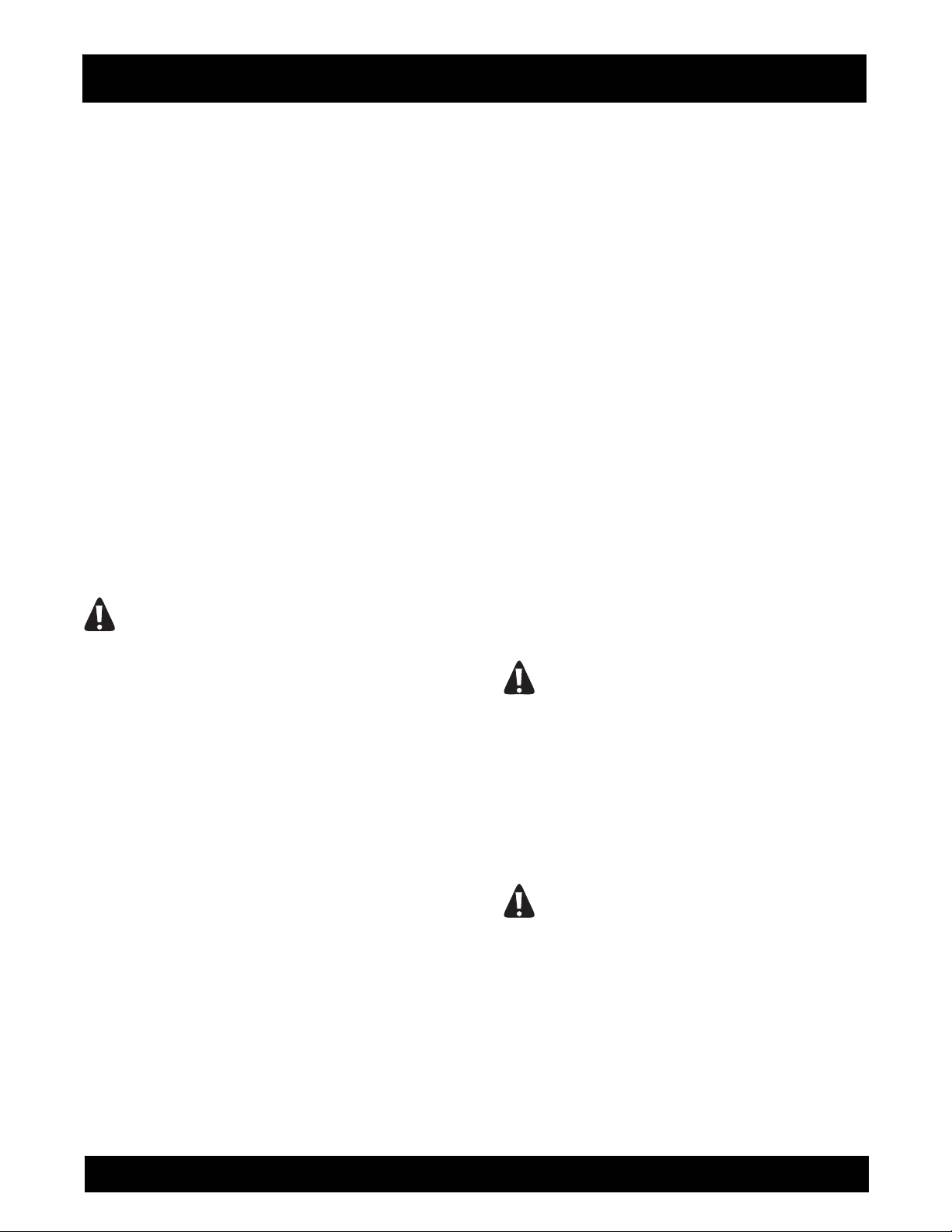
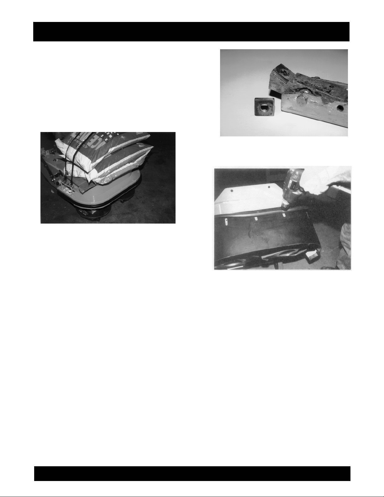
3) Tilt the SURFACE GRINDER back until the
operator handle comes in contact with the
surface. The SURFACE GRINDER may not be
in a stable position in this configuration. To
minimize the possibility of property damage
and/or personnel injury, properly secure an
appropriate weight to the handle for added
stability. Other means can be utilized to support
the frame and provide proper machine sta
Appropriate wheel chocks are also
recommended. FIGURE 1.
DANGER
bility.
EXERCISE EXTREME CAUTION WHEN
WORKING NEAR OR UNDER THE SURFACE
GRINDER WITH THE OPERATOR HANDLE
TILTED BACK IN THE SERVICE POSITION. IF
THE SURFACE GRINDER IS NOT POSITIONED IN
A STABLE CONFIGURATION, WITH ADEQUATE
COUNTERWEIGHT PROPERLY SECURED,
UNEXPECTED MOVEMENT CAN ALLOW THE
SURFACE GRINDER TO FALL BACK TO THE
WORK SURFACE. THE RESULT CAN BE
PROPERTY DAMAGE AND/OR PERSONAL
INJURY.
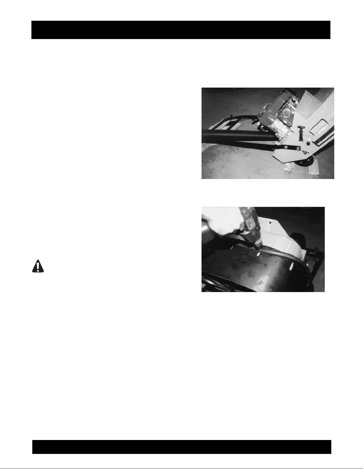
4) Using the 7/16-inch wrench, install the wrap-
around rubber skirt P/N 29018-88 around the
outside perimeter surrounding the multiaccessory discs. Secure with cap screws P/N
106499-007 and washers P/N 29018-090. The
original bumper and cap screws can also be
utilized as an alternative attachment method.
The notches in the rubbers skirt are provided as
a means to compensate for multi-accessory
attachment wear (if applicable). Adjust the
location of the rubber skirt to provide the
necessary clearance between it and the work
surface. Improper clearance will accelera
wear. FIGURE 2.
FIGURE 1
FIGURE 2
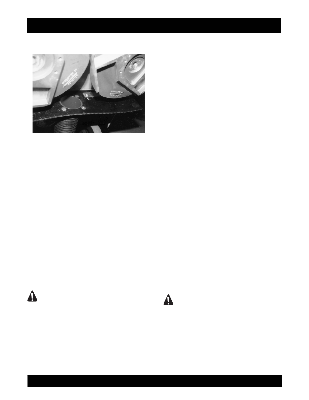
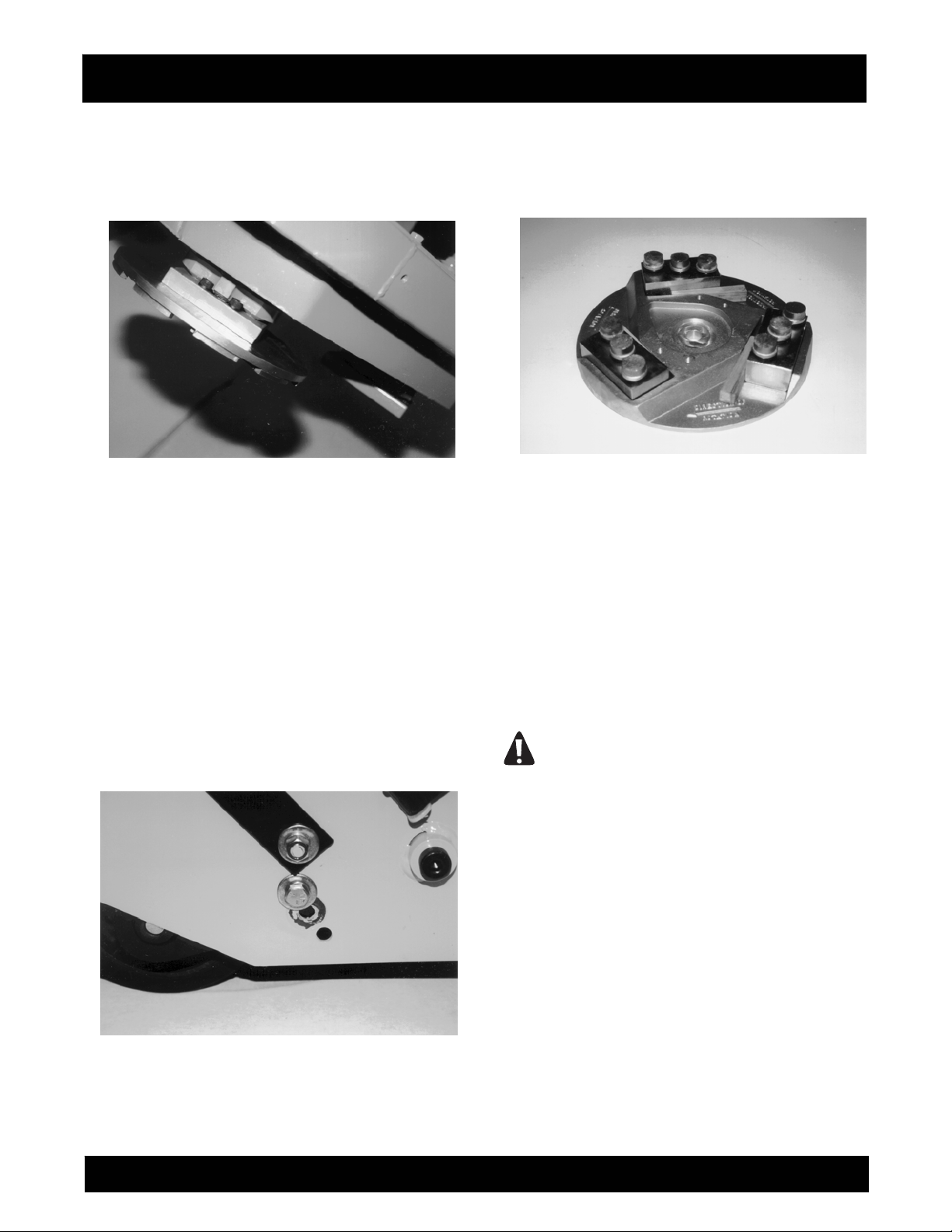
5) Using the 1/2-inch wrenches, the rectangular
rubber skirt P/N 29018-089 is attached to the
middle support member of the main frame.
Proper installation will have the hose attach
fitting that is riveted to the skirt facing the rear of
the machine. The notches in the rubber skirt are
provided as a means to compensate for multiaccessory attachment wear (if applicable).
Adjust the location of the rubber skirt to provide
the same clearance
rubber skirt P/N 29018-088. The skirt straps PN
29018-092 provide additional support for the
rear skirt assembly. Properly secure with the cap
screws PN 06500-007 and self-locking nuts P/N
08233-005. FIGURE 3.
as with the wrap-around
te skirt
DFG-SERIES SURFACE GRINDERS OPERATION AND PARTS MANUAL REV #4 (05/28/09) PAGE 16
Page 17
ASSEMBLY INSTRUCTIONS/OPERATIONS
FIGURE 3
6) Assemble the two each, hose clamps P/N
14821-012 over the PN 290018-093 vacuum
hose. Install the vacuum hose over the vacuum
hose attach fittings. Determine that the
configuration minimizes potential kinks or
depressions, which can reduce the airflow.
Secure the hose clamps tight with the
screwdriver.
7) The DFG-1000 Safety and Dust Shield
Assembly Kit can be removed by reversing the
above procedure and reinstalling the original
bumper P/N 29018-016
8) Return the SURFACE GRINDER to its normal
operating position.
9) If the SURFACE GRINDER is powered by a
gasoline engine, reconnect the engine spark
plug wire. If powered by an electric motor and
the machine is to be used immediately,
reconnect the extension cord or SURFACE
GRINDER to the power source. Determine that
the ON/OFF switch located on the operator
handle is in the OFF position.
DANGER
UNEXPECTED MACHINE START UP CAN
RESULT IN PROPERTY DAMAGE AND/OR
PERSONAL INJURY.
Before Starting the Engine
FILLING THE ENGINE CRANKCASE WITH OIL.
Applications: DFG/G SURFACE GRINDER.
Tools Required:
1 each, small, clean funnel.
The DFG/G Series SURFACE GRINDER is
equipped with a Honda GX340 gasoline engine. This
engine is normally not pre-serviced at the factory
and will require the addition of oil in the crankcase
before being placed in service. Consult the material
supplied by the engine manufacturer for the engine
that has been ordered with your SURFACE
GRINDER. Carefully review this material to become
familiar with specific operating characteristics,
recommendations and service requirements.
1) Determine the location(s) of both the oil filler and
oil drain plug(s).
2) Wipe oil, dust and accumulated dirt from the
filler plug area.
Using the funnel, fill the engine crankcase with a
3)
high grade motor oil. Consult the material
supplied by the engine manufacturer for proper
amount, weight and service classification.
4) Replace the oil filler plug and tighten. Wipe off
any excess oil spilled on the engine crankcase
and SURFACE GRINDER.
5) Do not operate the engine unless proper oil level
is maintained as per the material supplied by the
engine manufacturer.
FILLING THE DFG/G SERIES ENGINE FUEL
TANK.
Tools Required:
1 each, small, clean funnel.
CAUTION
Never mix oil with gasoline. Four cycle engines
are not designed to be operated with oil mixed
with the gasoline.
1) Determine the location of the fuel tank filler cap.
2) Carefully clean the filler cap and surrounding
area to insure that no dirt or debris falls into the
fuel tank. Remove the filler cap.
DFG-SERIES SURFACE GRINDERS OPERATION AND PARTS MANUAL REV #4 (05/28/09) PAGE 17
Page 18
ASSEMBLY INSTRUCTIONS/OPERATIONS
3) Using the funnel, fill the fuel tank with fresh,
clean fuel according to the specifications
outlined in the material supplied by the engine
manufacturer. Do not overfill the tank or spill any
fuel. If the fuel tank incorporates a screen mesh
to prevent debris from falling into the tank, do
not remove to increase the fill rate. Replace the
filler cap. Wipe away any excess spilled fuel.
DANGER
MANY FUELS ARE EXTREMELY FLAMMABLE.
DO NOT SMOKE NEAR THE FUEL TANK. DO
NOT FILL THE FUEL TANK WITH THE ENGINE
RUNNING OR IF IT IS HOT. ALLOW AMPLE TIME
BETWEEN EACH REFUELING FOR THE ENGINE
TO COOL.
Operation
THEORY OF OPERATION.
Application: All Models.
The DFG Series SURFACE GRINDERS operate on
the principle of various multi-accessory attachments
being utilized at rotational speeds to make direct
contact with a work surface. Various types of multi-
accessory attachments are secured to recesses
provided in two, counter-rotating, aluminum discs
located on the bottom of the machine. The specific
type of multi-accessory attachment utilized during
the grinding process directly affects the type of
material removed, the material removal rate and the
resulting flatness and smoothness of the surface.
The grinding process is directly controlled by these
conditions:
1) The use of a suitable mechanism (multi-
accessory attachment) of proper design a
configuration to grind the work surface and
remove material while delivering acceptable
service life.
2) Sufficient static weight supporting the multi-
accessory attachment to allow it to effectively
penetrate the work surface and remove material.
3) Adequate horsepower capable of propelling the
multi-accessory attachment against the work
surface to deliver acceptable productivity rates.
Since no two materials are exactly alike, no two work
surface materials can be penetrated and removed
by the exact same method. The n
grinding process, along with operator experience,
skill and common sense, would suggest that efficient
ature of the
nd
and productive material removal is a matter of trial
and error. Combinations of multi-accessory
attachment type, condition, and feed rate are direct
factors that will also determine the overall success of
the job application.
MULTI-ACCESSORY ATTACHMENTS AND
APPLICATIONS.
Application: All Models
While individual multi-accessory attachment design
and configuration may vary, basic operational
characteristics are identical: impact upon a work
surface materi
material. This common operational characteristic has
led to the development of the following popular
multi-accessory attachments:
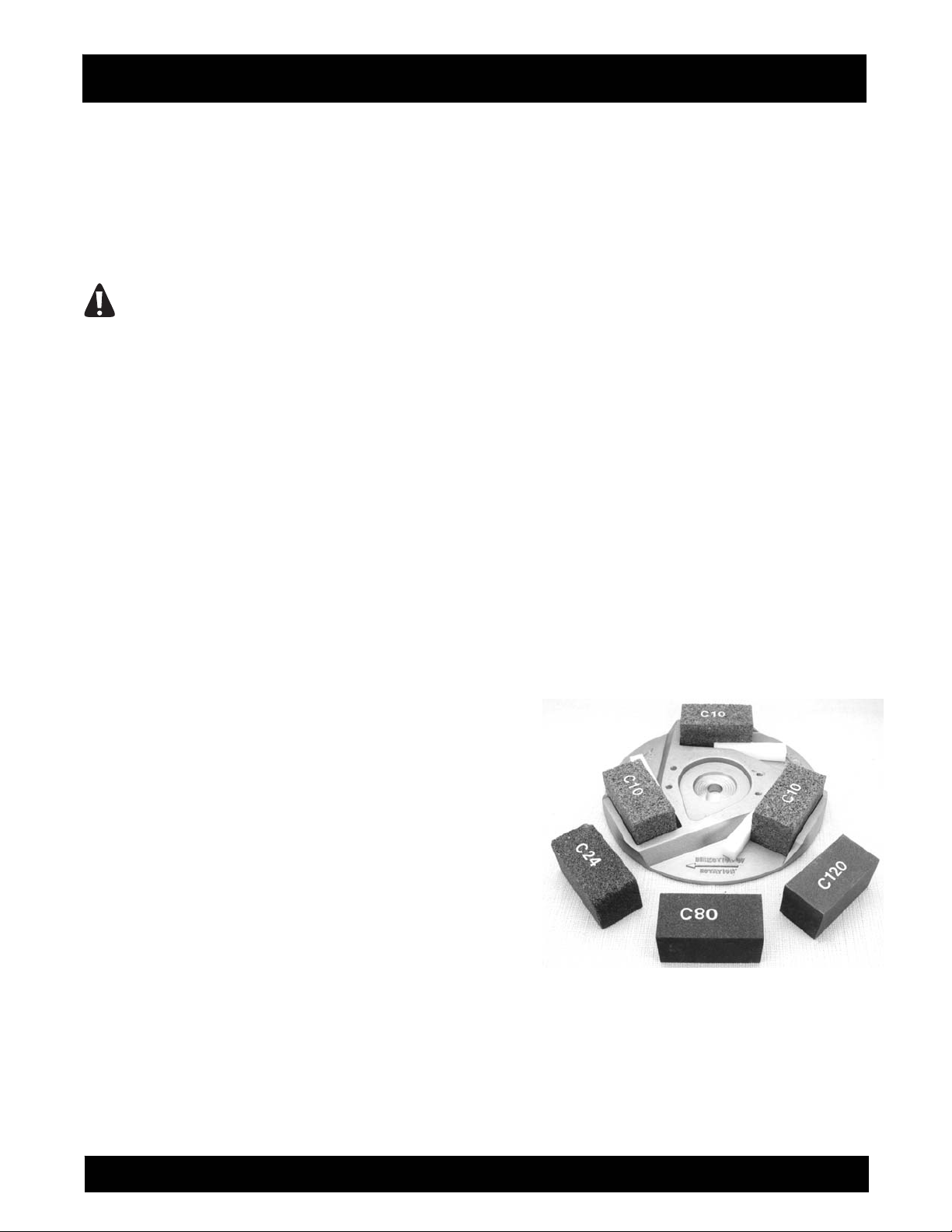
Grinding Stones
Grinding stones are available in a number of grades,
including: C06 extra coarse, C10 coarse, C24
medium, C80 fine and C120 super fine grade.
FIGURE 4. All stones incorporate silicon carbide as
the abrasive medium and employ a clay binder as
the matrix material. Vitrified type stones utilize an
oven baking process that produces greater service
life over other manufa
material wears away, it exposes new, sharp, edges
of the imbedded silicon carbide material. All stones
have the identical 2" x 2" X 4" dimensions and are
secured to the machine by the use of a plastic
wedge.
FIGURE 4
The designation system for the grinding stones
utilizes a system similarly utilized for most abrasive
products: the larger the number, the finer the grain
structure and usually, the smoother resulting finish.
al and remove a percentage of the
cturing processes. As the clay
DFG-SERIES SURFACE GRINDERS OPERATION AND PARTS MANUAL REV #4 (05/28/09) PAGE 18
Page 19

ASSEMBLY INSTRUCTIONS/OPERATIONS
a) The C06 and C10 coarse grade stones are the
most popular utilized stones and result in maximum
material removal rates. They are utilized for general
grinding and the removal of trowel marks, high spots
and rough sections on concrete surfaces. The
average service life is approximately 4 to 10 hours.
b) The C24 medium grade stone will result in lower
material removal rates. It is utilized for finer finish
grinding of concrete and rough grinding on terrazzo
and other types of stone floor configurations. The
average service life is approximately 6 to 10 hours.
c) The C80 fine grade stone will result in still lower
material removal rates. It is utilized for polishing
concrete and medium grinding on terrazzo and other
types of stone floor configur
mixture only. The average service life is
approximately 8 to 20 hours.
d) The C120 super fine grade stone will result in the
lowest material removal rates. It is utilized for final
polishing on terrazzo and other types of stone floor
configurations with a water/slurry mixture only. The
average service life is approximately 40 to 75 hours.
Tungsten Carbide Grinding Block
This multi-accessory attachment is most often
utilized on larger concrete grinding projects where
increased production and service life are required.
The block utilizes tungsten carbide balls
approximately 1/16 inch diameter that are deposited
in a molten matrix material during the manufacturing
process at a controlled r
layer deposit of tungsten carbide balls in the matrix
material. As the softer matrix material wears with
use, it exposes a new layer of fresh tungsten carbide
balls to continue the grinding process. The tungsten
carbide grinding block is considerably more
aggressive than the C10 silicon carbide grinding
stone. With the ability to renew itself during usage,
the normal life expectancy for this accessory can
approach several hundred hours. The nominal
dimensions for the tungsten carbide grinding block is
2" x 2" x 4" and is secured to the machine with a
plastic wedge. FIGURE 5.
ations with a water/slurry
ate. The end effect is a multi
FIGURE 5
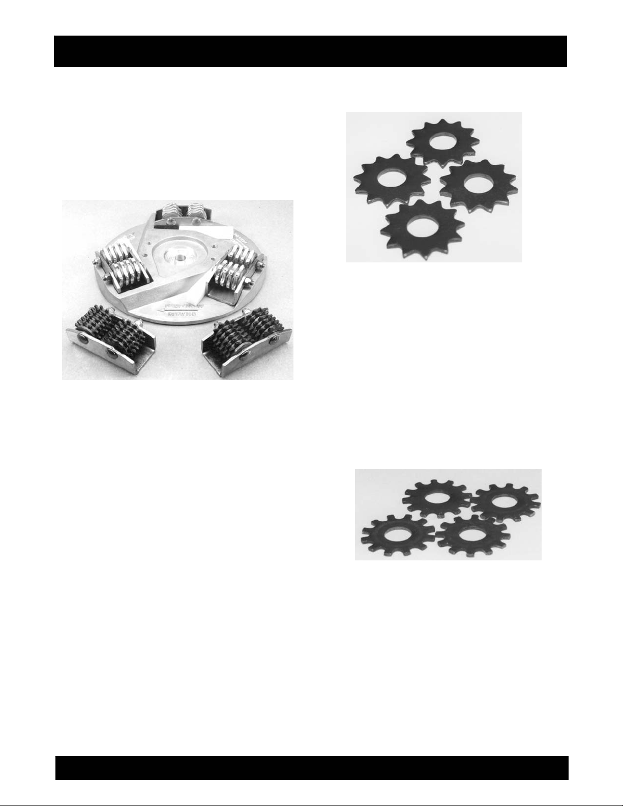
Scarifier Blocks
These multi-accessory attachments are comprised
of flails and spacer washers secured in a rigid steel
case. FIGURE 6. Rotation of the two multi-accessory
discs causes the flails to impact against the work
surface with a variety of results. Scarifier blocks are
secured to the machine with plastic wedges.
Several factors directly affect the selection of a flail
design for a specific job application:
a) The type and amount of material to be removed
from the work surface. Materials of higher yield and
tensile strengths a
material to be removed will generally be the first
factors under consideration.
b) Purchase cost versus service life. The original
purchase cost of plain, heat-treated steel flails must
be compared against the substantially higher costs
of the tungsten carbide insert flails. In turn, these
costs must be compared to anticipated service life.
All flails will eventually wear to the point of requiring
replacement. The amount of unproductive time
spent to replace worn flails on a job can be
substantially greater than the actual replacement
cost of many flails. It then becomes a ba
between purchase cost, productivity, service life and
labor cost.
c) Surface finish and texture. The finest grained
surface finish available from the scarifying process is
comparable to a "swept or broomed" like finish. If a
smooth, flat finish is desired, the scarifying process
must be followed with a grinding or polishing type
process. Many job requirements may call for large
amounts of material to be removed, but followed
with additional specifications requiring a finer
surface finish or texture. Many times these jobs
dictate the use of an aggressive flail configuration
because of productivity and cost considerations.
Less aggressive flail configurations c
long with the actual volume of
lance
an then be
DFG-SERIES SURFACE GRINDERS OPERATION AND PARTS MANUAL REV #4 (05/28/09) PAGE 19
Page 20
ASSEMBLY INSTRUCTIONS/OPERATIONS
utilized for the final finishing sequence. Generally
speaking, the more aggressive the flail
configurations, the more coarse the resulting finish
and texture.
Many flail configurations are available to meet a
wide variety of job applications and surface material
specifications. To give additional perspective to each
configuration, a rating system of 1 to 10 (10 being
highest) has been devised.
FIGURE 6
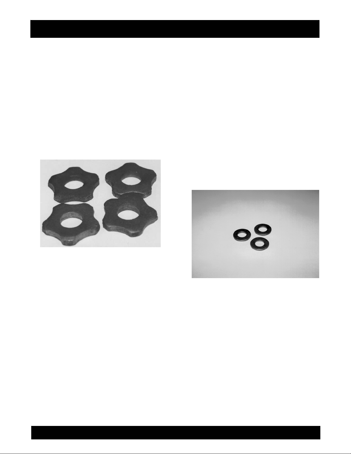
Star Flail
The star flail is manufactured from high carbon steel
that is through ha
is highly effective for light cleaning or scarifying and
delivers a finer surface finish texture. FIGURE 7.
Suggested Applications:
1) Removal of thin coatings and encrusted
accumulations.
2) Cleaning concrete and asphaltic surfaces
3) Removing thick material build-ups of greases,
paints, oils, vegetable powders and some resins
from floors.
4) Light scarifying prior to the application of
coatings, toppings or sealers.
rdened for additional service life. It
FIGURE 7
COST 1
PRODUCTIVITY 3
SERVICE LIFE 1
The star flail should be replaced when the outside
diameter is worn to approximately 1-5/16 inch or the
inside diameter elongates to approximately 3/4 inch.
Beam Flail
The beam type flail is manufactured from high
carbon steel that is through hardened for additional
service life. It is highly effective for scabbling or
scarifying and delivers medium to coarse surface
finish texture. FIGURE 8.
FIGURE 8
Suggested Applications:
1) Medium duty asphalt and concrete scarifying.
2) Descaling steel decks.
3) Removing thick material build-ups of grea
paints, oils, vegetable powders and some resins
from floors.
4) Dried, fully cured, carpet and tile adhesive
removal.
ses,
DFG-SERIES SURFACE GRINDERS OPERATION AND PARTS MANUAL REV #4 (05/28/09) PAGE 20
Page 21
ASSEMBLY INSTRUCTIONS/OPERATIONS
COST 1
PRODUCTIVITY 5
SERVICE LIFE 2
The beam flail should be replaced when the outside
diameter is worn to approximately 1-5/16 inch or the
inside diameter elongates to approximately 3/4 inch.
Pentagonal Flail
The pentagonal type flail is manufactured from high
carbon steel that is through hardened for additional
service life. Each section of the five sided design
features a small, tungsten carbide insert that is held
in position with copper brazing. It is highly effective
for scabbling or scarifying and delivers medium to
coarse finish texture. FIGURE 9.
FIGURE 9
Suggested Applications:
1) Heavy duty a
2) Heavy duty descaling of steel decks.
The pentagonal flail is designed for more aggressive
and rapid removal of a surface in comparison to the
beam flail. The addition of the tungsten carbide
inserts contributes to its long service life and higher
production rates. The use of tungsten carbide is also
the main reason for the cost differential between it
and the other flails. The design configuration yields a
rather coarse surface finish and texture. For many
job applications, this finish and texture will be
satisfactory. Some applications may require a
additional smoothing process. If the resulting surface
finish is too coarse to meet specifications, it can be
smoothed with the use of the star or beam flail.
sphalt and concrete scarifying.
n
COST 10
PRODUCTIVITY 8
SERVICE LIFE 10
The pentagonal flail should be replaced when two
successive tungsten carbide inserts break off or the
inside diameter elongates to approximately 3/4 inch.
In service, the flail body will wear much faster than
the tungsten carbide inserts. The copper brazing
used to weld the inserts into the body can fail and an
insert break off. The flail can still be used in service.
It will just wear a little faster and more uneven in that
particular are
can be utilized until body wear will no longer support
the tungsten carbide inserts.
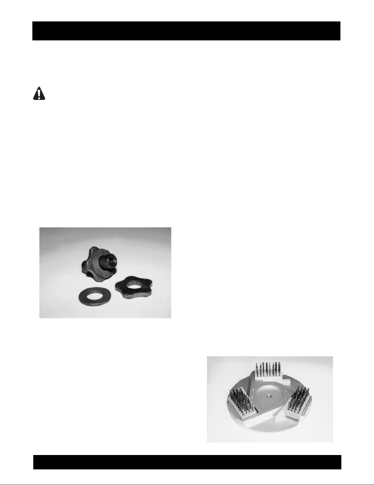
Spacer Washer
Spacer washers are stamped from high carbon steel
and heat-treated for additional service life. FIGURE
10.
FIGURE 10
Spacer washers serve the following functions:
1) Reduces the number of flails required to be
mounted on the scarifier block, thus reducing
purchase and operational costs.
2) Arrange the flails in a sequence or pattern that
minimize "blind" or "open" spots. Normally, at
ast one spacer washer is inserted between two
le
consecutive flails. A scarifier block set up with
only star, beam or pentagonal flails will not
penetrate the work surface at satisfactory rates.
This configuration will minimize the hammering
or impact action of the flails.
Variances in material thickness and manufacturing
processes can affect the final thickness of both flails
and spacer washers. Because of this occurrence,
trial and error is important for assembling flails and
a. As a general rule, a pentagonal flail
DFG-SERIES SURFACE GRINDERS OPERATION AND PARTS MANUAL REV #4 (05/28/09) PAGE 21
Page 22
ASSEMBLY INSTRUCTIONS/OPERATIONS
spacer washer on the scarifier block. By mixing and
matching flails and spacer washers of specific
thicknesses, the required number of components
can be assembled on a block in a minimum amount
of time.
DANGER
USE ONLY FACTORY SUPPLIED SPACER
WASHERS ON THE SCARIFIER BLOCK. OTHER
WASHER TYPES AND/OR CONFIGURATIONS
CAN PRODUCE ABNORMAL WEAR AND
ELONGATION, RESULTING IN COMPLETE
SEPARATION FROM THE SCARIFIER BLOCK.
INADVERTENT SPACER WASHER SEPARATION
CAN LEAD TO PROPERTY DAMAGE AND/OR
PERSONAL INJURY.
Scarifier Block Bushing
Scarifier block bushings are designed to be
discarded whenever the flails are replaced. FIGURE
11. Normal wear should be uniform about the
bushing circumference.
FIGURE 11
Uneven bushing wear would suggest the following
problems:
1) Inadequate free play exists between the
flails/spacer washers and the scarifier block
case. If the flails and spacer washers do not
have complete freedom of movement, they will
not be capable of properly rotating about the
scarifier block bushing. The result is bushing
wea
r usually confined to two locations that are
180 degrees apart. Variances in flail and spacer
washer thicknesses affect free play when
assembled on the scarifier block.
Because free play is also created during the
scarifying process due to actual flail and spacer
washer wear, a certain amount of "tightness"
can sometimes be tolerated without affecting the
service life of the bushings and flails. The
specific amount of "tightness" can usually be
determined through trial and error. If the flails
and spacer washers
scarifier block, remove an appropriate flail or
washer and reassemble the block. If a short,
operational test indicates normal component
wear patterns, the apparent problem has been
solved. A general rule for consideration: it is
better to have the flails and spacer washers a
"little too loose than a little too tight".
2) Mixing both worn and new flails on the scarifier
block. Proper flail action against the work
surface material requires that the flails be of the
same a
various inside and outside dimensions will not
impact the work surface material with the same
intensity and deliver the same results. Flail
bushing wear is directly proportional to the
amount of force it must supply against each
individual flail. When a bushing can no longer
supply adequate force against the flails, it will
break, allowing the flails to be hurdled against
the inside of the SURFACE GRINDER frame.
The more aggressive flails require greater forces
to keep them contained on the block. These
forces, in turn, create faster and/or uneven
bushing wear rates.
Because sca
component of the actual scarifying process, it is
important that each bushing be inspected on a
regular basis to determine proper structural
integrity.
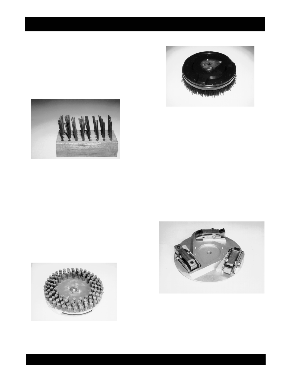
Wire brushes
Typical applications include light scarifying and
cleaning of concrete, asphalt, steel and tile surfaces.
Wire brushes are secured to the machine with
plastic wedges. FIGURE 12.
FIGURE 12
pproximate dimensions. Flails with
rifier bushings are a critical
appear too tight on the
DFG-SERIES SURFACE GRINDERS OPERATION AND PARTS MANUAL REV #4 (05/28/09) PAGE 22
Page 23
ASSEMBLY INSTRUCTIONS/OPERATIONS
Wire brushes are available in a number of flat wire
sizes and resulting configurations. With continuous
use, the flat wire will take a "set" that can limit
effectiveness and overall productivity. FIGURE 13.
For best results, flat wire brushes should be rotated
end for end in the aluminum multi-accessory discs a
minimum of once for every one hour of operation.
External weight applied to the SURFACE GRINDER
will not normally increase productivity rates and only
accelerate flat wire wear rates.
FIGURE 13
Floor Brushes
Eleven inch diameter, silicon carbide impregnated,
floor brushes are availa
designs for general maintenance and cleaning
projects. FIGURE 14. They are especially effective
cleaning soiled concrete floors with the addition of
water soluble solvents. These types of brushes are
directly mounted to the multi-accessory discs with
the included 1/2 inch x 2 inch long Grade 5
capscrews. A kidney shaped drive plate is provided
on the back side of the brush. This drive plate fits
into a recess provided in the multi-accessory disc.
FIGURE 15. To maximize bristle service life, it is
recommended that the silicon impregnated brushes
be rotated between multi-accessory discs a
minimum of once for every one hour of operation.
FIGURE 14
ble in a number of styles and
FIGURE 15
SCRAPE-R-TACH® Industrial Floor Coatings
Removal System
This multi-a
remove many urethanes, epoxies, paints, mastics
and other, similar material accumulations from
concrete floor surfaces. FIGURE 16. Each assembly
utilizes two tungsten carbide inserts set at a precise
angle. The rotating inserts "cut and shave" against
the work surface material with a "scraping" action
that removes materials with highly productive
results. To increase the effectiveness of the inserts,
the scraper block design incorporates a Lord® type
rubber mount that helps absorb damaging shocks
while allowing the inserts to more easily follow local
ations in the surface contour. Units are secured
vari
to the machine with plastic wedges.
FIGURE 16
The productivity of the product is directly dependent
upon the yield and tensile strength of the material
being removed. Material thickness has also shown
to have a direct effect on overall productivity. For
example, the SCRAPE-R-TACH system is a highly
productive method for removing thick paint
accumulations from factory floors. Production rates
ccessory attachment is designed to
DFG-SERIES SURFACE GRINDERS OPERATION AND PARTS MANUAL REV #4 (05/28/09) PAGE 23
Page 24
ASSEMBLY INSTRUCTIONS/OPERATIONS
of up to several hundred square feet per hour can be
realized. However, many thin film ( ie: 5 mill
thickness and thinner) urethane coatings present a
much more difficult removal problem. Since removal
rates are also directly affected by applied down
force, up to 300 lbs of external weight can be
applied to the SURFACE GRINDER to increase
productivity. Cement blocks or stacked bags of
cement make excellent weights and can be secured
with "bungy" cords or other means with the provided
holes in the top cover. FIGURE 17.
FIGURE 17
Each insert provides 8 scraping edges. As an edge
become dull and worn, the insert can be turned and
reinstalled to expose a new, sharp edge. FIGURE
18. When all 4 edges of one side become worn and
dull, the insert c
additional 4 edges.
Many materials such as adhesives, rubber deposits
and mastics have the tendency to extrude or smear
rather than shear from the concrete floor material.
The occurrence is also aggravated by higher
ambient temperatures. This problem can be
significantly reduced with the addition of various
amounts of water or a water saturated, fine sand
combination placed on the floor. The use of the
Safety and Dust Shield Assembly with the
SURFACE GRINDER is highly recommended to
contain the water/sand slurry mixture from damaging
surrounding walls and other vertic
FIGURE 19.
an be turned over to expose an
al surfaces.
FIGURE 18
FIGURE 19
To index the tungsten carbide insert, proceed as
follows:
Tools required:
1 each, 5/32 Allen wrench.
1) Clean the SCRAPE-R-TACH unit with a suitable
safety solvent to remove excess material buildup. Remove as much foreign material from the
female hexagon socket area of the capscrew.
This will allow the wrench to make full contact
and maximize the torque transfer to the cap
screw.
DFG-SERIES SURFACE GRINDERS OPERATION AND PARTS MANUAL REV #4 (05/28/09) PAGE 24
Page 25

ASSEMBLY INSTRUCTIONS/OPERATIONS
CAUTION
Follow all safety precautions for the safety
solvent.
2) Remove the cap screw from the unit. Clean the
newly exposed areas of the insert and SCRAPER-TACH unit with the safety solvent. Clean and
inspect the threaded holes found in older units
for excess wear. New style SCRAPE-R-TACH
units feature a through hole design.
3) Index the insert to expose a new edge. Reinstall
the capscrew and apply a torque value that
properly seats the insert firmly against the body
of the unit.
CAUTION
An insufficient seating torque value will allow the
insert to become loose from the unit body,
resulting in premature component wear and
improper scraping action. An excessive torque
value will strip the threads of the capscrew or
unit body.
4) Determine that the unit body is free to rotate
about the 5/16 inch diameter capscrew that
retains the body to the unit. A body that does not
freely rotate indicates that a material build-up
exists between the rubber mount and retaining
capscrew exits. This build-up must be removed
by disassembling the body from the unit and
cleaning all contact areas with the safety
solvent. FIGURE 20.
The SCRAPE-R-TACH system is designed to be
installed with the edge of the tungsten carbide
inserts facing the direction of rotation. Markings are
provided to indicate proper direction of rotation.
FIGURE 20
CAUTION
Installing the SCRAPE-R-TACH system with the
tungsten carbide inserts facing opposite the
rotation direction will not deliver satisfactory
material removal rates and result in premature
component wear requiring early replacement.
Multi-Segmented, Dry Diamond Disc
Many times increased concrete removal rates can
be achieved with the use of multi-segmented, dry
diamond discs. FIGURE 21. These discs are
designed to operate dry or can also be utilized with
water. If the wet option is chosen, an external source
for providing water must be devised. No provision for
water use is provided with the SURFACE GRINDER.
Typical discs are approximately 10 inch diameter
and feature up to 20 diamond segments that are
welded or brazed to each assembly.
To install the multi-segmented, dry diamond discs,
the standard, aluminum, multi-accessory discs are
first removed from the SURFACE GRINDER. The
diamond discs fasten directly to the gimbal heads
with 3/8 inch di
capscrews. FIGURE 22. The rear wheel assembly is
then placed in the lowest position to compensate for
the thickness variance of the diamond discs.
FIGURE 23.
FIGURE 21
ameter x 1 inch long Allen head
DFG-SERIES SURFACE GRINDERS OPERATION AND PARTS MANUAL REV #4 (05/28/09) PAGE 25
Page 26
ASSEMBLY INSTRUCTIONS/OPERATIONS
To maximize the service life of the diamond
segments, it is recommended that the blades be
rotated between gimbal heads a minimum of once
for every 8 hours of operation.
FIGURE 22
Diamond Segment Block
The diamond insert block is designed to compliment
the multi-segmented diamond disc where a quick
changeover feature to other attachments is desired.
Diamond segments are retained into a steel block
assembly and deliver up to 5 times greater
productivity rates than the silicon carbide stones.
FIGURE 24. The design resists clogging while
delivering a conservative service life up to 15 times
longer than the stones. Diamond is the ideal choice
for larger concrete removal projects and the removal
of epoxies, p
FIGURE 23
The concept is especially useful for removing a thin
layer of concrete in final preparation for a new
coating application. Can be used in both wet and dry
aints and many thin film coatings.
job applications. Worn inserts are easily replaced in
a matter of seconds. Service life is dependent upon
many variables, but can approach 35,000 square
feet per set, making it a cost efficient solution for
many job applications.
FIGURE 24
INSTALLING A MULTI-ACCESSORY
ATTACHMENT (not including multi-segmented, dry
diamond discs) IN THE COUNTERROTATING
DISCS.
Application: All Models.
Tools Required:
1 each, Small Hammer
Parts Required:
6 each, P/N 29019-017 Mounting Wedge
DANGER
WHEN INSTALLING A MULTI-ACCESSORY
ATTACHMENT ON THE SURFACE GRINDER
ALWAYS WEAR THE APPROPRIATE SAFETY
EYEWEAR AND APPAREL TO MINIMIZE THE
POTENTIAL FROM FLYING DEBRIS. FLYING
DEBRIS CAN RESULT IN PROPERTY DAMAGE
AND/OR PERSONAL INJURY.
1) If the SURFACE GRINDER is powered by an
engine, disconnect the spark plug wire. If
powered by an electric motor, properly
disconnect the extension cord or SURFACE
GRINDER from the power source.
2) Tilt the SURFACE GRINDER back until the
operator handle comes in contact with the
surface. The SURFACE GRINDER may not be
in a stable position in this configuration. To
minimize the possibility of property damage
and/or personal injury, properly secure an
DFG-SERIES SURFACE GRINDERS OPERATION AND PARTS MANUAL REV #4 (05/28/09) PAGE 26
Page 27

ASSEMBLY INSTRUCTIONS/OPERATIONS
appropriate weight to the handle for added
stability. Other means can also be utilized to
support the frame and provide proper machine
stability. Appropriate wheel chocks are also
recommended. FIGURE 25.
DANGER
EXERCISE EXTREME CAUTION WHEN
WORKING NEAR OR UNDER THE SURFACE
GRINDER WITH THE OPERATOR HANDLE
TILTED BACK IN THE SERVICE POSITION. IF
THE SURFACE GRINDER IS NOT POSITIONED IN
A STABLE CONFIGURATION, WITH ADEQUATE
COUNTERWEIGHT PROPERLY SECURED,
UNEXPECTED MOVEMENT CAN ALLOW THE
SURFACE GRINDER TO FALL BACK TO THE
WORK SURFACE. THE RESULT CAN BE
PROPERTY DAMAGE AND/OR PERSONAL
INJURY.
FIGURE 25
3) Mount the multi-accessory attachment into the
slots provided in the multi-accessory discs. If the
attachment is directional in design, determine
that its mounting position in the disc allows for
proper operation.
4) Force a Mounting Wedge P/N 229019-017 into
the area between the multi-accessory
attachment and the inside rib of the aluminum
disc by hand. The straight side of the mounting
wedge contacts the multi-accessory attachment.
The angled side of the mounting wedge contacts
the rib of the disc. FIGURE 26. An improper
mounting configuration is depicted in FIGURE
27.
FIGURE 26
FIGURE 27
DANGER
DO NOT OPERATE THE SURFACE GRINDER
WITH THE 229019-017 MOUNTING WEDGES IN
AN IMPROPER MOUNTING CONFIGURATION.
MOUNTING A WEDGE BETWEEN THE MULTIACCESSORY ATTACHMENT AND THE OUTSIDE
RIB OF THE ALUMINUM DISC CAN ALLOW THE
WEDGE TO COME IN DIRECT CONTACT WITH A
VERTICAL WALL AND/OR FLOOR
OBSTRUCTION. SUCH OCCURRENCE CAN
RESULT IN LOSS OF MACHINE CONTROL,
PROPERTY DAMAGE AND/OR PERSONAL
INJURY.
BEFORE OPERATING THE SURFACE GRINDER
WITH ANY MULTI-ACCESSORY ATTACHMENT,
DETERMINE THAT NO PORTION OF THE
ATTACHMENT AND/OR MOUNTING WEDGE
EXTENDS BEYOND THE NORMAL PERIMETER
OF THE ALUMINUM DISC.
DFG-SERIES SURFACE GRINDERS OPERATION AND PARTS MANUAL REV #4 (05/28/09) PAGE 27
Page 28

ASSEMBLY INSTRUCTIONS/OPERATIONS
5) Using a hammer, strike the wider side of the
mounting wedge with controlled, direct blows to
firmly seat the multi-accessory attachment into
the aluminum disc. Usually one or two direct
blows will be sufficient to properly retain the
attachment.
CAUTION
Do not apply excessive impact force to the
mounting wedge to cause splitting. Once the
multi-accessory attachment is seated in the
aluminum disc, further impact force on the
wedge will not increase the seating force.
CAUTION
Improper seating force created by an excessive
blow to the mounting wedge will not allow the
attachment to properly release from the
aluminum disc if direct contact with a foreign
object is made. Such occurrence can result in
property damage and/or personal injury. The
correct seating force for a specific job
application is that which is sufficient to retain
the attachment, yet still allows it to release from
the aluminum disc when direct contact with a
foreign object is made.
6) Determine that the multi-accessory attachment
is in full contact with the aluminum disc. If not in
proper contact, refer to REMOVING A MULTIACCESSORY ATTACHMENT (not including
multi-segmented, dry diamond blades) FROM
THE COUNTERROTATING DISCS for proper
removal procedures.
7) Return the SURFACE GRINDER to its normal
operating position.
8) If the SURFACE GRINDER is powered by an
engine, reconnect the engine spark plug wire. If
powered by an electric motor and the machine is
to be used immediately, reconnect the extension
cord or SURFACE GRINDER to the power
source. Determine that the ON/OFF switch
located on the operator handle is in the OFF
position.
DANGER
UNEXPECTED MACHINE START UP CAN
RESULT IN PROPERTY DAMAGE AND/OR
PERSONAL INJURY.
REMOVING A MULTI-ACCESSORY ATTACHMENT
(not including multi-segmented, dry diamond discs)
FROM THE COUNTERROTATING DISCS.
Application: All Models.
Tools Required:
1 each, Small Hammer
1 each, Drift Punch or small, Pry Bar
DANGER
WHEN REMOVING A MULTI-ACCESSORY
ATTACHMENT FROM THE SURFACE GRINDER,
ALWAYS WEAR APPROPRIATE SAFETY
EYEWEAR AND APPAREL TO MINIMIZE THE
POTENTIAL FROM FLYING DEBRIS. FLYING
DEBRIS CAN RESULT IN PROPERTY DAMAGE
AND/OR PERSONAL INJURY.
1) If the SURFACE GRINDER is powered by an
engine, disconnect the spark plug wire. If powered
by an electric motor, disconnect the extension cord
or SURFACE GRINDER from the power source.
2) Tilt the SURFACE GRINDER back until the
operator handle comes in contact with the surface.
Follow the instructions for this procedure as outlined
in INSTALLING A MULTI-ACCESSORY
ATTACHMENT (not including multi-segmented, dry
diamond blades) IN THE COUNTERROTATING
DISCS.
3) The multi-accessory attachment can be
removed by both the use of a drift punch or small,
pry bar. If utilizing the drift punch, strike the narrow
end of the mounting wedge with controlled, direct
blows until the attachment is released from the
aluminum disc. If utilizing the pry bar, position the
bar between the aluminum disc and the attachment.
Use controlled, direct blows to the bar in order to
force the attachment loose from the aluminum disc.
FIGURE 28.
DFG-SERIES SURFACE GRINDERS OPERATION AND PARTS MANUAL REV #4 (05/28/09) PAGE 28
Page 29

ASSEMBLY INSTRUCTIONS/OPERATIONS
FIGURE 28
CAUTION
Do not utilize excessive force when removing a
multi-accessory attachment with the pry bar.
Excessive force can result in damage to the
aluminum disc. Proper removal techniques by
both methods will result in minimal damage to
the aluminum disc.
4) Return the SURFACE GRINDER to its normal
operating position.
5) If the SURFACE GRINDER is powered by an
engine, reconnect the spark plug wire. If
powered by an electric motor and the machine is
to be used immediately, reconnect the extension
cord or SURFACE GRINDER from the power
source. Determine that the ON/OFF switch
located on the operator handle is in the OFF
position.
DANGER
UNEXPECTED MACHINE START UP CAN
RESULT IN PROPERTY DAMAGE AND/OR
PERSONAL INJURY.
TRANSPORTING THE SURFACE GRINDER.
Application: All Models.
The SURFACE GRINDER has an operational weight
that prohibits one person from loading and/or
unloading it alone by conventional, physical efforts.
DANGER
DO NOT ATTEMPT TO LIFT THE SURFACE
GRINDER UP INTO A TRANSPORTATION
VEHICLE WITH THE USE OF ONE PERSON
ALONE. DO NOT ATTEMPT TO LOWER THE
SURFACE GRINDER FROM A
TRANSPORTATION VEHICLE WITH THE USE OF
ONE PERSON ALONE. LIFT AND/OR LOWER
THE SURFACE GRINDER ONLY BY THE USE OF
A POWER TAILGATE UNIT, A SUITABLE HOIST
UNIT OF PROPER CAPACITY AND/OR
CONFIGURATION OR BY THE USE OF A
PROPER QUANTITY OF PERSONNEL IN
PROPER PHYSICAL CONDITION.
1) A lifting bail device can be used to facilitate
lifting by a mechanical device incorporating a
chain and suitable attachment device. The
location of the lifting bail may not always locate
the exact position of the center of gravity for the
SURFACE GRINDER. Lifting handles are also
provided on both sides of the transmission case.
These handles can be utilized by personnel
whenever lifting/lowering the SURFACE
GRINDER or as attachment points for a chain
sling whenever a suitable hoisting device is
utilized. FIGURE 29.
DANGER
EXERCISE EXTREME CAUTION WHEN
UTILIZING A MECHANICAL DEVICE FOR
LIFTING THE SURFACE GRINDER. UTILIZE THE
MECHANICAL DEVICE IN ACCORDANCE TO
BOTH ITS STATED STATIC AND DYNAMIC
LOADING ENVELOPES. DO NOT UTILIZE THE
MECHANICAL DEVICE UNTIL THIS
INFORMATION IS PROPERLY KNOWN AND
UNDERSTOOD BY ALL APPLICABLE
PERSONNEL. FAILURE TO PROPERLY UTILIZE
THE MECHANICAL DEVICE CAN RESULT IN
PROPERTY DAMAGE AND/OR PERSONAL
INJURY.
2) When transporting the SURFACE GRINDER on
a motor vehicle, the fuel tank breather vent (if so
equipped) must be completely closed to eliminate
the accidental seepage of fuel and resulting potential
fire and environmental hazards.
3) To minimize the possibility of damage to the
SURFACE GRINDER, always transport in its
normal, upright position. All equipment must be
secured in/on vehicles with suitable strapping or tiedowns. Personnel should not be transported in the
same compartment as equipment and fuel supplies.
DFG-SERIES SURFACE GRINDERS OPERATION AND PARTS MANUAL REV #4 (05/28/09) PAGE 29
Page 30

ASSEMBLY INSTRUCTIONS/OPERATIONS
Consult applicable OSHA, AGA, CGA, etc.
regulations for the proper transportation flammable
gases.
ADJUSTING THE OPERATOR HANDLE HEIGHT.
Application: All Models.
The DFG Series SURFACE GRINDER incorporates
a handle that can be adjusted to compensate for
variances in operator heights. Three adjustment
heights are provided. Correct handle height can
increase overall machine productivity and reduce
operator fatigue.
FIGURE 29
Tools Required:
1 each, 3/4 wrench or suitable alternative.
1) Using the wrench, loosen the 1/2-inch hexagon
nuts from the stud assemblies that ret
handle to the main frame.
2) Using the wrench, remove the 1/2-inch cap
screws that retain the handle in position on the
main frame.
DANGER
EXERCISE EXTREME CAUTION WHEN
REMOVING THE RETAINING CAPSCREWS
FROM THE MAIN FRAME. WHEN THE FINAL
CAPSCREW IS REMOVED, THE HANDLE IS
PROVIDED WITH NO EXTERNAL SUPPORT AND
WILL IMMEDIATELY DROP TO THE FLOOR.
SUCH OCCURRENCE CAN RESULT IN
PROPERTY DAMAGE AND/OR PERSONAL
INJURY.
3) Reposition the operator handle in the desired
location that aligns the hole in the handle with
the threaded hole in the main frame. Replace
ain the
the 1/2-inch hexagon cap screws and properly
tighten with the wrench. FIGURE 30.
4) Using the wrench, properly tighten the 1/2-inch
hexagon nuts on the stud assemblies that retain
the handle to the main frame.
FIGURE 30
STARTING THE DFG/E SERIES ELECTRICALLY
POWERED SURFACE GRINDER ON THE
JOBSITE.
1) Position the SURFACE GRINDER on a flat and
level surface of firm foundation.
2) Determine that the ON/OFF switch located on
the oper
UNEXPECTED MACHINE START UP CAN
RESULT IN PROPERTY DAMAGE AND/OR
PERSONAL INJURY.
3) Select the appropriate operating voltage for the
electric motor. The motor is designed to operate
from a clean, 20 ampere, 115 VAC, 60 Hz
nominal or a clean, 10 ampere, 230 VAC, 60 Hz
nominal power source. A clean power source
refers to the amperage available on the
individual electrical circuit selected. Additional
electrical products already utilizing the same
circuit will reduce the available amperage,
resulting in starting and operational difficulties.
A voltage switch (115/230 VAC, 60 Hz) is
provided on the motor. For added security, the
voltage switch can be locked in position with a
combina
shank length. FIGURE 31.
ator handle is in the OFF position.
DANGER
tion or keyed lock with an extended
DFG-SERIES SURFACE GRINDERS OPERATION AND PARTS MANUAL REV #4 (05/28/09) PAGE 30
Page 31

ASSEMBLY INSTRUCTIONS/OPERATIONS
CAUTION
Operating the SURFACE GRINDER from a power
source of improper voltage and amperage will
result in un-repairable damage to the electric
motor and related controls.
FIGURE 31
4) Providing proper voltage and amperage levels to
the electric motor is essential to obtain
maximum productivity and service life. Low
voltage and amperage levels will cause the
motor to overheat. The motor is equipped with
automatic thermal protection device that will stop
it before major internal damage can result. After
the motor has cooled to an acceptable
temperature level, the switch must be manually
activated to restart. FIGURE 32.
FIGURE 32
To minimize the voltage drop to the motor, all
extension cords should be copper stranded, 8
AWG or larger. A NEMA 6-20R twist-lock type
receptacle is provided with the DFG/E Series
SURFACE GRINDER as a standard accessory.
The twist clock feature allows the extension cord
to be pulled by the SURFACE GRINDER without
becoming detached. Wire the NEMA 6-20R
receptacle to the appropriate extension cord that
will be coupled to the NEMA 6-20P plug
provided on the SURFACE GRINDER. FIGURE
33.
FIGURE 33
DANGER
PROPERLY INSPECT ALL EXTENSION CORDS
AND WIRING DEVICES FOR STRUCTURAL
INTEGRITY. DO NOT UTILIZE A CORD WITH A
WORN OR CUT OUTER JACKET MATERIAL. DO
NOT UTILIZE A CORD WITH EXPOSED INNER
WIRES OR INSULATION MATERIAL. DO NOT
UTILIZE A CORD THAT HAS BEEN REPAIRED
WITH ELECTRICAL TAPE. USE OF A AN
EXTENSION CORD OF IMPROPER STRUCTURAL
INTEGRITY CAN RESULT IN PROPERTY
DAMAGE AND/OR PERSONAL INJURY.
DANGER
ALL ELECTRICAL WIRING MUST BE INSTALLED
AND/OR APPROVED IN ACCORDANCE TO
LOCAL ELECTRICAL CODES AND PRACTICES.
AN IMPROPER WIRING INSTALLATION CAN
RESULT IN PROPERTY DAMAGE AND/OR
PERSONAL INJURY.
5) Determine that the power outlet to be utilized is
properly grounded. This can be accomplished
with proper testing equipment and procedures. If
there are any questions regarding the suitability
of a specific power outlet, contact the Customer
Service Department for assistance BEFORE
DFG-SERIES SURFACE GRINDERS OPERATION AND PARTS MANUAL REV #4 (05/28/09) PAGE 31
Page 32

ASSEMBLY INSTRUCTIONS/OPERATIONS
utilizing the SURFACE GRINDER. There is no
charge for this service. A qualified electrician
can also be consulted. If a 115 VAC power
outlet is selected, it is recommended that a
properly tested, externally mounted, ground fault
circuit interrupter (GFCI) be utilized at all times
as an additional safety precaution. Ground fault
circuit interrupters are not available for operation
on 230 VAC. FIGURE 34.
FIGURE 34
DANGER
FOR MAXIMUM PROTECTION AGAINST A
FAULT, ALWAYS CONFIGURE THE GROUND
FAULT CIRCUIT INTERRUPTER TO BE
PLUGGED INTO THE EXTENSION CORD. A
CONFIGURATION WITH THE GROUND FAULT
CIRCUIT INTERRUPTER PLACED BETWEEN THE
POWER SOURCE AND THE EXTENSION CORD
WILL NOT AFFORD MAXIMUM PROTECTION
AGAINST A POTENTIAL FAULT.
6) Couple the NEMA 6-20R receptacle and the
NEMA 6-20P plug together.
7) Grasp the operator handle with firm gripping.
When starting the electric motor, apply a down
force directly to the operator handle to help
reduce the amount of machine weight against
the work surface. Turn the ON/OFF switch to the
ON position. Reduce the amount of applied
down force on the operator handle as the
electric motor attains its operational speed.
When operating on 115 VAC, the electric motor
will require additional starting time to help
compensate for the additional starting amperage
requirement. This time is usually within two
seconds of a
ctivating the ON/OFF switch.
8) The DFG/E Series electrically powered
SURFACE GRINDER is not equipped with a
centrifugal clutch assembly. The electric motor is
directly coupled to the multi-accessory discs by
a V-belt/spur gear transmission.
DANGER
AS SOON AS THE ELECTRIC MOTOR HAS
STARTED, THE OPERATOR MUST BE IN A
POSITION TO ASSUME DIRECT AND FULL
CONTROL OF THE SURFACE GRINDER.
FAILURE TO ASSUME DIRECT AND FULL
CONTROL CAN RESULT IN PROPERTY
DAMAGE AND/OR PERSONAL INJURY.
9) The DFG/E Series electrically powered
SURFACE GRINDER is stopped by moving the
ON/OFF switch located on the operator handle
to the OFF position. For safety considerations, it
is also recommended that the extension cord be
disconnected from both the SURFACE
GRINDER and electric power source whenever
the SURFACE GRINDER is not in use on the
job site.
STARTING THE DFG/G SERIES GASOLINE
POWERED SURFACE GRINDER ON THE
JOBSITE.
1) Position the SURFACE GRINDER on a flat and
level surface of firm foundation.
2) Refer to the material supplied by the engine
manufacturer for the correct starting, operation
and stopping procedures.
3) The DFG/G Series SURFACE GRINDER is
equipped with a centrifugal clutch assembly. The
clutch is designed to engage at approximately
2400 RPM engine speed. Normal operation of
the clutch will allow the engine to operate a
designated idle speed without the multiaccessory discs rotating. If the multi- accessory
discs rotate below the designated engine idle
speed, do not continue to operate the
SURFACE GRINDER until the problem has
been properly corrected. Consult the Customer
Service Department for specific information.
There is no charge for this service.
t its
DFG-SERIES SURFACE GRINDERS OPERATION AND PARTS MANUAL REV #4 (05/28/09) PAGE 32
Page 33

ASSEMBLY INSTRUCTIONS/OPERATIONS
DANGER
AS SOON AS THE CENTRIFUGAL CLUTCH
ASSEMBLY BECOMES ENGAGED, THE
OPERATOR MUST BE IN A POSITION TO
ASSUME DIRECT AND FULL CONTROL OF THE
SURFACE GRINDER. FAILURE TO ASSUME
DIRECT AND FULL CONTROL CAN RESULT IN
PROPERTY DAMAGE AND/OR PERSONAL
INJURY.
DANGER
DO NOT OPERATE A GASOLINE ENGINE IN
CLOSED SPACES WITHOUT PROPER
VENTILATION. GASOLINE ENGINES PRODUCE
CARBON MONOXIDE FUMES. BREATHING
CARBON MONOXIDE FUMES CAN RESULT IN
PROPERTY DAMAGE AND/OR PERSONAL
INJURY. EXCESSIVE LEVELS OF CARBON
MONOXIDE CAN CAUSE DEATH.
4) Stop the engine in accordance with the
instructions as described in the material supplied
by the engine manufacturer.
OPERATING THE SURFACE GRINDER ON THE
JOBSITE.
Application: All Models.
DANGER
THE GRINDING PROCESS PRODUCES
EXCESSIVE NOISE, VIBRATION AND FLYING
DEBRIS. ALL OPERATORS AND WORK
PERSONNEL IN THE VICINITY OF THE SURFACE
GRINDER MUST WEAR APPROPRIATE SAFETY
EYE WEAR AND HEARING PROTECTION
DEVICES. OTHER SAFETY APPAREL AND/OR
PROCEDURES, DEEMED NECESSARY BY
SUPERVISORY PERSONNEL MUST ALSO BE
WORN AND/OR PRACTICED BY ALL
APPROPRIATE PERSONNEL.
DANGER
EXERCISE EXTREME CAUTION WHEN
OPERATING THE SURFACE GRINDER IN THE
VICINITY OF DECK INSERTS, PIPES, COLUMNS,
OPENINGS, LARGE CRACKS, UTILITY OUTLETS
OR ANY OBJECT PROTRUDING FROM THE
SURFACE. CONTACT WITH SUCH OBJECTS
CAN LEAD TO LOSS OF MACHINE CONTROL,
RESULTING IN PROPERTY DAMAGE AND/OR
PERSONAL INJURY.
DANGER
DO NOT OPERATE A GASOLINE ENGINE IN
CLOSED SPACES WITHOUT PROPER
VENTILATION. GASOLINE ENGINES PRODUCE
CARBON MONOXIDE FUMES. BREATHING
CARBON MONOXIDE FUMES CAN RESULT IN
PROPERTY DAMAGE AND/OR PERSONAL
INJURY. EXCESSIVE LEVELS OF CARBON
MONOXIDE CAN CAUSE DEATH
1) The SURFACE GRINDER incorporates counter-
rotating discs for mounting a wide variety of
multi-accessory attachments. The
counterrotating action results in a "self
propelled" effect that substantially enhances
machine control and reduces fatigue as long as
the multi-accessory attachment does not come
in direct contact with a protruding obstruction
from the floor. Direct contact with such an
obstruction can result in rapid and jerky
directional movement of the machine. In most
operating situations, direct contact with a
protruding obstruction from the floor will result in
the multi-accessory atta
dislodged from the counter-rotating disc. This
occurrence is intended to protect the SURFACE
GRINDER from excessive damage and allow
the operator to remain in proper control of the
machine.
DANGER
ALWAYS MAINTAIN PROPER CONTROL OF THE
SURFACE GRINDER. IF AN OPERATOR LOOSES
CONTROL OF THE MACHINE, A "RUNAWAY"
SURFACE GRINDER CAN RESULT IN
PROPERTY DAMAGE AND/OR PERSONAL
INJURY. BECAUSE OF THE UNIQUE
OPERATING CHARACTERISTICS OF THE
SURFACE GRINDER, THERE IS NO PROVISION
FOR THE ELECTRIC MOTOR/ENGINE TO
AUTOMATICALLY STOP IF THE OPERATOR
FAILS TO MAINTAIN PROPER CONTROL.
DANGER
chment becoming
WHEN OPERATING THE SURFACE GRINDER ON
ABOVE GROUND FLOOR LEVELS, EXERCISE
EXTREME CAUTION TO PREVENT LOSS OF
CONTROL THAT COULD ALLOW THE MACHINE
AND/OR OPERATOR TO FALL DOWN TO
LOWER LEVELS. SUCH AN OCCURRENCE CAN
DFG-SERIES SURFACE GRINDERS OPERATION AND PARTS MANUAL REV #4 (05/28/09) PAGE 33
Page 34

ASSEMBLY INSTRUCTIONS/OPERATIONS
RESULT IN PROPERTY DAMAGE AND/OR
PERSONAL INJURY.
2) Productivity rates with the various multi-
accessory attachments can be increased with
the addition of external weight being applied to
the area over the counter-rotating discs.
FIGURE 36. Maximum allowable external weight
is 300 lbs. Exceeding this figure can result in
permanent structural damage to the SURFACE
GRINDER. Provisions for securing the weight by
the means of strapping or other, appropriate
methods is provided.
FIGURE 36
DANGER
DO NOT OPERATE THE SURFACE GRINDER
WITHOUT ALL EXTERNAL WEIGHT PROPERLY
SECURED TO THE MAIN FRAME. A SUDDEN
CHANGE IN MOVEMENT OR DIRECTION CAN
ALLOW THE UNSECURED WEIGHT TO FALL
OFF THE SURFACE GRINDER, RESULTING IN
LOSS OF MACHINE CONTROL, PROPERTY
DAMAGE AND/OR PERSONAL INJURY. THIS
PROCEDURE IS ESPECIALLY IMPORTANT
WHEN OPERATING THE SURFACE GRINDER ON
FLOORS AND/OR SURFACES ABOVE GROUND
LEVEL.
3) Proper operator posture and stance will enhance
operational safety a nd overall productivity.
FIGURE 38. For most job applications, operate
the engine at maximum, governed speed.
Consult the material supplied by the engine
manufacturer and the SPECIFICATIONS section
for specific information.
4) The wide variety of potential work surface
materials along with the corresponding variety of
job site environments, makes it impossible to
develop a standardized operating procedure for
the SURFACE GRINDER. Use of the SURFACE
GRINDER will require constant trial and error
testing until satisfactory results are achieved.
Experience gained over time and common
sense will help minimize the amount of
necessary testing. Many factors will directly
affect the operating parameters and/or
techniques utilized for a specialized job
application. Some of these factors include:
a) Work surface material yield and tensile
values. As a general rule, these values will
determine material removal rate per unit of
time. Materials with high yield and tensile
values will characteristically resist/limit
material penetration. For such materia
accepted procedure is to make a number of
multiple passes over the work surface rather
than attempt to make a single, deep pass.
The net effect is to actually increase
productivity: more material removed in less
time. Other added benefits to this technique
are decreased vibration, less operator
fatigue and increased component service
life.
FIURE 38
b. Higher material removal rates can
sometimes be achieved by making a series
of shallow passes 90 degrees to each other
to form
is especially useful when removing deeper
accumulations of rubber, paint, dirt debris,
etc. from industrial floors.
a waffle like pattern. This technique
ls, the
DFG-SERIES SURFACE GRINDERS OPERATION AND PARTS MANUAL REV #4 (05/28/09) PAGE 34
Page 35

ASSEMBLY INSTRUCTIONS/OPERATIONS
5) The grinding process on many work surface
materials can produce sparks, dust and other
foreign particle contamination.
DANGER
SPARKS PRODUCED BY THE ACTIONS OF
MULTI-ACCESSORY OPTIONS AGAINST THE
WORK SURFACE (FOR EXAMPLE: STRIKING
ANCHOR BOLTS) MAY COME IN CONTACT
WITH MATERIALS THAT CAN RESULT IN A FIRE
AND/OR EXPLOSION. THIS OCCURRENCE CAN
RESULT IN PROPERTY DAMAGE AND/OR
PERSONAL INJURY.
DANGER
THE CREATION OF DUST AND OTHER FOREIGN
PARTICLE CONTAMINATION FROM THE
OPERATIONAL PROCESS CAN RESULT IN
PROPERTY DAMAGE AND/OR PERSONAL
INJURY. FOR SUCH OPERATING CONDITIONS,
ALWAYS WEAR A NIOSH/MSHA APPROVED
DUST/MIST RESPIRATOR. CONSULT
APPLICABLE OSHA REGULATIONS FOR
SPECIFIC INFORMATION.
6) Dust and other particle contamination can be
controlled by the following methods:
a) The SURFACE GRINDER is equipped with
a 1-1/2, 2 or 3 inch outside diameter vacuum
tube adaptor located at the rear of the
machine. An industrial type vacuum system
and front shield assembly can be attached
to the SURFACE GRINDER to
remove/control dust and other particle
contamination from the work surface. A hose
clamp is sometimes required to properly
secure the vacuum hose to the vacuum
tube. FIGURE 39.
FIGURE 39
DANGER
ALWAYS UTILIZE A VACUUM SYSTEM
DESIGNED TO OPERATE WITHIN THE SPECIFIC
JOB SITE REQUIREMENT. DUST MATERIAL CAN
MEET CLASS II OR CLASS III SPECIFICATIONS
OF THE NATIONAL ELECTRIC CODE® FOR
HAZARDOUS LOCATION CLASSIFICATIONS.
CONSIDERATION MUST ALSO BE GIVEN TO
THE CREATION OF HAZARDOUS TYPE
MATERIALS REQUIRING SPECIFIC DISPOSAL
PROCEDURES. DETERMINE THAT THE VACUUM
SYSTEM IS PROPERLY DESIGNED TO OPERATE
WITHIN THESE ATMOSPHERES. CONSULT
CURRENT NATIONAL ELECTRIC CODE®, OSHA
AND ENVIRONMENTAL PROTECTION AGENCY
REGULATIONS FOR SPECIFIC INFORMATION.
b) Water/sand slurry mixture applied directly to
the work surface can be an effective method
of reducing the effects of grinding and other
material removal processes. This method
can be a productive alternative when
removing adhesives containing asbestos. A
negative effect of this method is that the
water/sand slurry mixture can be classified
as a hazardous material, requiring proper
disposal procedures.
7) Normal usage of the SURFACE GRINDER will
allow the build-up and accumulation of work
surface materials on interior surfaces. It is highly
recommended that both the interior and exterior
surfaces be properly cleaned after the
completion of each usage.
CAUTION
Failure to properly clean the interior surfaces of
the SURFACE GRINDER can result in dried
material build-up and accumulation directly
affecting bearing service life.
DANGER
EXERCISE EXTREME CAUTION WHEN
UTILIZING ANY SOLVENT TO REMOVE
ACCUMULATED MATERIALS FROM THE
SURFACES OF THE MACHINE AND RELATED
COMPONENTS. MANY SOLVENTS ARE
FLAMMABLE. DO NOT SMOKE OR INTRODUCE
FLAME IN THE WORK AREA. PROVIDE
ADEQUATE VENTILATION AND WEAR PROPER
SAFETY APPAREL.
DFG-SERIES SURFACE GRINDERS OPERATION AND PARTS MANUAL REV #4 (05/28/09) PAGE 35
Page 36

ASSEMBLY INSTRUCTIONS/OPERATIONS
DANGER
PROPERLY DISPOSE OF ALL ACCUMULATED
MATERIALS PER OSHA AND ENVIRONMENTAL
PROTECTION AGENCY CODES AND
REGULATIONS. MANY ACCUMULATED
MATERIALS CAN BE CLASSIFIED AS
HAZARDOUS AND REQUIRE PROPER
DISPOSAL PROCEDURES. CONTACT THE
APPLICABLE GOVERNMENT AND/OR PRIVATE
AGENCIES FOR SPECIFIC INFORMATION.
8) On job applications where the work process
creates a considerable amount of loose material,
it can become almost impossible to determine
proper material removal depths and the extent of
work already accomplished. The problem can be
compounded if a vacuum system is not utilized.
Loose material should be removed by sweeping
or other, appropriate processes and the
SURFACE GRINDER utilized until conditions
again warrant removing the accumulated
material.
STOPPING THE DFG/E SERIES ELECTRICALLY
POWERED SURFACE GRINDER.
1) Stopping the SURFACE GRINDER is
accomplished by moving the ON/OFF switch
located on the operator ha
position. For safety considerations, it is also
recommended that the extension cord be
disconnected from both the SURFACE
GRINDER and electric power source whenever
the SURFACE GRINDER is not in use on the
jobsite
STOPPING THE DFG/G SERIES GASOLINE
POWERED SURFACE GRINDER.
1) Stopping the SURFACE GRINDER is
accomplished by moving the engine throttle
control lever to the idle speed position (depicted
by the turtle). Machines powered by Honda
engines can be then stopped by further moving
the engine throttle control lever until the ignition
system is grounded.
2) Machines powered by other engines may utilize
a separate ON/OFF switch. If so equipped, turn
the switch to the OFF position. Consult the
material supplied by the engine manufacturer for
specific information.
ndle to the OFF
OPERATIONAL PARAMETERS AND TECHNIQUES
FOR THE DFG SERIES SURFACE GRINDER.
Application: All Models.
Early Age Grinding
Early age grinding is an alternative to floating and
trowelling. It gets it name from the fact that the
concrete is ground at an early age, after it h
but before it has gained much structural strength.
The process usually involves the following steps:
1) Normal screeding of the floor.
2) Smoothing the floor surface with a skip float.
3) Cover the floor with polyethane sheeting.
4) Removing the sheeting and grinding the floor
down a uniform depth of approximately 1/32 inch
within 24 to 48 hours of the initial pouring.
The C06 and C10 silicon carbide grinding stones are
usually used for the process, although the multi
segmented, dry diamond blades can be use as an
alternative with substantially greater productivity
rates. The main benefit of early age grinding is that it
eliminates late work in cold wea ther. With ordinary
finishing methods,
cold weather day might not get finished trowelled
until very late at night. With grinding, the
construction crew are able to leave the job at the
end of a normal work day and return 1 or 2 days
later to finish the job. Early age grinding may not
reduce the total number of work hours, but it usually
eliminates the need for work at overtime rates, which
can substantially increase total project costs.
One side benefit of early age grinding is that the
process demands less skill than conventional
floating and trowelling. This makes it an attractive
process where skilled crew personnel may not be
available. It is also an excellent procedure for
concrete floors that will be eventually covered by
carpet or an applied coating.
Definitions of floor flatness and levelness
The terms flatness and levelness have poorly
understood meanings in everyday speech, but have
important distinctions in floor construction.
Flatness is defined as planarity or lack of curvature.
A more simple definition is that a flat floor is smooth
and free of bumps and dips. An unflat floor is bumpy
and wavy. Levelness is defined as horizontality or
lack of slope. A level floor is horizontal. A floor that is
unlevel is sloped or tilted.
A floor can be flat, but still not level. Some floors are
specifically designed to be unlevel; they can be
a slab cast in the morning of a
as set
DFG-SERIES SURFACE GRINDERS OPERATION AND PARTS MANUAL REV #4 (05/28/09) PAGE 36
Page 37

ASSEMBLY INSTRUCTIONS/OPERATIONS
intentionally sloped for drainage considerations.
Very few, if any, floors are specifically designed to
be unflat. Unfortunately, many turn out that way.
Flatness and levelness are both desirable, but have
different implications for the floor user. Flatness is
critical where the user's main concern is the
behavior of wheeled type vehicles. Levelness is
critical where the user's main concern is with fixed
structures such as shelving, racks and the
placement of machine tools.
Exceptions exist, but for most users, flatness is more
important than levelness. The reasoning is that fixed
equipment can be shimmed or adjusted to
compensate. However, it is not as easy to adapt a
wheeled vehicle to a
allow for proper action.
Flatness and levelness also have different
implications for the floor contractor. Flatness is
determined mainly by finishing methods. Levelness
is determined mainly by the side forms.
Defined Versus Random Traffic Patterns
Floors are subject to two kinds of traffic patterns:
defined and random. On a defined traffic floor,
vehicle movement is confined to fixed paths. On a
random traffic floor, vehicles are free to roam,
though inevitably, some traffic patterns are used
more than others.
The distinction is important because the two kinds of
traffic demand different methods of measuring
surface regularity. On a defined traffic floor, a
continuous (or ne
the paths can be measured. But where traffic is
random, the possible travel paths are infinite in
number. What usually results is statistical sampling;
selected points or lines are checked and assumed
that they represent the whole floor surface.
The highest degree of surface regularity is found
among the defined traffic floors. Defined traffic floors
allow the designer and contractor to focus on a
limited number of critical areas. When a defined
traffic floors is out of tolerance, it is relatively easy to
identify the defects for correction---usually by
employing a grinding process.
How to Define Surface Regularity
Since the middle 1980s, new methods of defining
surface regularity have been adopted
standards. Older methods will continue to be
utilized, although they are less effective. The
following methods will be discussed:
1) The F number system for random traffic floors
floor that is not flat enough to
arly continuous) profile in each of
as national
2) The TR 34 system for defined traffic floors
Both methods are not of equal value. For random
traffic floors, F numbers provide the most complete
and consistent system. For defined traffic floors, the
TR34 system is superior.
The F number system utilizes a pair of numbers to
define surface regularity. The flatness number, Ff, is
based upon the curvature over a horizontal distance
of 24 inches. The levelness number, Fl, is based
upon the floor slope over a horizontal distance of 10
feet. The standard test for F numbers is specified in
ASTM E1155 and/or most recent version.
With both Ff and Fl, higher numbers mean greater
surface regul
zero to infinity, almost all floors have F numbers
between 10 and 100 for both flatness and levelness.
Since the scale is linear, an Ff50 floor is exactly
twice as flat as an Ff25 floor.
Most F number specifications are written in a two tier
format. The overall F numbers apply to the floor
taken as a whole. The local F numbers apply to
each individual slab and are usually only one half to
two thirds the overall values.
The overall F numbers are not just simple averages.
ASTM E1155 covers how to combine F numbers.
The two tier format encourages contractors to
achieve good surface regularity while allowing for
minor defects. The attempt is to pour the entire floor
to the specified overall F numbers. If, for instance,
the construction crew has a bad day and fails to
meet the specified overall numbers for the slab, the
slab can still be accepted provided it meets the
specified local numbers.
Such an occurrence serves as a warning to the crew
that it must strive for a better performance on later
slabs, so as to bring the overall F numbers up to the
specified values. If a slab fails to meet even the
specified local numbers, it must be repaired or
replaced, but such failures seldom occur if all parties
understand what is expected from the start.
Designers are not obligated to use this two tier
format. Some designers specify a single F number
pair (Ff and Fl) which applies to each individual slab.
But this also raises the risk that slabs will be
rejected.
FIGURE 40 depicts the overall and minimum F
numbers for various floor classes. The floor
arity. Though the scale ranges from
DFG-SERIES SURFACE GRINDERS OPERATION AND PARTS MANUAL REV #4 (05/28/09) PAGE 37
Page 38

ASSEMBLY INSTRUCTIONS/OPERATIONS
classification is from the American Concrete
Institute. Although the F number system is only a
few years old, it offers these advantages:
a) The system controls both flatness and levelness.
b) There is a standard test method.
c) The system recognizes the statistical nature of
profile testing on random traffic floors.
d) The system is infinitely variable.
FIGURE 40
One of the major limitations of the F number system
is that it does not control the surface regularity at
joints. Because joints are statistical anomalies, the
ard test method forbids measurements within
stand
24 inches. The designer specifying by F number has
two methods to accommodate the problem. The first
solution is to locate joints at locations where surface
regularity is not important. The second solution is to
design specifications for the joints themselves.
The TR 34 tolerances for defined traffic floors
The TR 34 System divides defined traffic floors into
three categories:
a) Superflat
b) Category 1
c) Category 2
For each category, the TR 34 System specifies limits
for three properties:
Property 1 is the difference in elevation between two
points 12 inches apart, measured in the direction of
vehicle traffic. This is the levelness tolerance.
Property 2 is the difference in slope over 24 inches
measured in the direction of vehicle traffic. This is
the flatness tolerance. It is identical as the 24 inch
curvature utilized in the F number system.
Property 3 is the difference in elevation between
opposite points in the left and right wheel path,
measured perpendicular to the direction of vehicle
traffic. As with Property 1, it is a levelness tolerance.
The TR 34 System specifies different values for
Property 3 depending upon whether the distance
between left and right wheel paths is more or less
than 5 nominal feet
The Superflat category is intended for very narrow
aisle warehouses where the highest standards are
required. Category 1 is suggested for very narrow
aisle warehouses where the vertical lift height is
between 26 and 43 feet. Category 2 is for very
narrow aisle warehouses where the vertical lift
height is under 26 feet and the use of low rise,
automatically controlled vehicles. No matter which
category of surface regularity is specified, it is
accomplished by measuring elevations on 12 inch
centers. This is very simil
but with an important distinction. In an F number
survey, the elevation profiles are made on the floor
at random. With the TR 34 System, the survey
measurements are made on the actual paths of the
vehicles that will utilize the floor.
Improving the wear resistance of concrete floors
by grinding with the DFG Series SURFACE
GRINDER
Poor wear resistance can often be traced back to a
surface that is weaker than underlying levels of the
pour. This an occurrence can result from bad
finishing techniques, improper curing or early
freezing.
Where surface weakness is a problem, grinding can
be a solution. The process is similar to the early age
technique. The grinding depth is typically 1/16 to 1/8
inch. A large project should not be a
small test area has proven that the technique will
produce the desired results. Usually only a square
yard of floor is ground with the normal wear tests
performed.
Repair costs can be minimized by grinding only
those floor areas that accommodate traffic. For
example, in a pallet rack warehouse, it may be
necessary to grind only the aisle areas and not
under any of the racks. The grinding process can
adversely affect the surface regularity. Where
specific properties are important, it may be
ar to an F number survey,
ttempted until a
DFG-SERIES SURFACE GRINDERS OPERATION AND PARTS MANUAL REV #4 (05/28/09) PAGE 38
Page 39

ASSEMBLY INSTRUCTIONS/OPERATIONS
necessary to survey the floor during the grinding
process to ensure that flatness and levelness
specifications are maintained.
Cleaning concrete floors to improve the wear
resistance with the DFG Series SURFACE
GRINDER
Clean concrete floors have a longer service life than
dirty, poorly maintained floors. Loose debris
produces three-bodied wear by allowing particles to
roll between the traffic and the floor surface. With
some types of debris, especially when lodged in
vehicle wheels, wear can be immediate and severe.
The DFG Series SURFACE GRINDER can be
utilized with a number of multi accessories to clean
and extend concrete floor service life. The SCRAPER-TACH® floor coatings removal system readily
removes food, oil and rubber accumulations from
high traffic floor areas. The Clean Sweep™ silicon
impregnated, rota
biodegradable detergent applied to floors removes
ground in dirt and debris from shop and industrial
floors. Dry diamond segmented discs and blocks
can be utilized to remove surface imperfections.
ry brushes along with a
DFG-SERIES SURFACE GRINDERS OPERATION AND PARTS MANUAL REV #4 (05/28/09) PAGE 39
Page 40

MAINTENANCE/SERVICE
Maintenance/Service
PREVENTATIVE MAINTENANCE CHECK LIST.
Application: All Models.
The normal operation of the SURFACE GRINDER
produces extreme dirt and dust, along with levels of
random vibration. Before operating the SURFACE
GRINDER, the following service list should be
accomplished. This list is for reference only and is
not intended to be all inclusive. Other subject areas
can be added at the discretion of the owner(s)
and/or operator(s):
1) Check all fasteners for proper torque values. If a
fastener requires re-torquing, consult a torque
chart for proper value. Properly discard and
replace any worn fastener with a factory
approved, replacement part.
2) Check the V-belts for wear. Adjust or replace as
necessary. Check pulleys for wear
alignment. Many loose materials created as a
result of operating processes can be extremely
abrasive.
3) Keep the SURFACE GRINDER clean. Wash the
unit after each use. Keep loose materials from
accumulating around engine cooling fins.
Determine that the interior sections of the frame
are free of material build-ups. Such build-ups
can restrict the operating process and present a
potential safety hazard. Clean and remove any
material build-up from the SURFACE GRINDER
after each use.
4) Engine service life can be extended with proper
air cleaner ma
supplied by the engine manufacturer for specific
information.
5) Check for proper oil level. Always use clean,
high quality engine oil. Change oil as required.
Consult the material supplied by the engine
manufacturer for specific information
6) Remove material accumulations from the
exterior surfaces of the electric motor. The
electric motor is a totally enclosed, fan cooled
(TEFC) design. Keep the fan fins clear of
material accumulations to enhance airflow over
the motor exterior for cooling purposes.
intenance. Consult the material
and proper
DANGER
DO NOT PERFORM PREVENTATIVE
MAINTENANCE CHECKS WITH THE ENGINE OR
ELECTRIC MOTOR RUNNING. STOP THE
POWER SOURCE AND DISCONNECT THE
SPARK PLUG OR EXTENSION CORD BEFORE
PERFORMING ANY MAINTENANCE TO THE
SURFACE GRINDER. IF GASOLINE ENGINE
POWERED, RECONNECT THE SPARK PLUG
BEFORE RESTARTING THE ENGINE. IF
ELECTRIC MOTOR EQUIPPED, TURN THE
ON/OFF SWITCH TO THE OFF POSITION
BEFORE RECONNECTING THE EXTENSION
CORD. IMPROPER PROCEDURES CAN RESULT
IN PROPERTY DAMAGE AND/OR PERSONAL
INJURY.
CHECKING V-BELT TENSION AND ALIGNMENT.
Application: All Models.
Proper V-belt tension and alignment are essential for
smooth transmission of horsepower and extended
service life. Improper tension and alignment will
accelerate V-belt wear and contribute to decreased
productivity. The V-belt is tensioned at the factory
with the maximum recommended tension force.
Check the belt tension at least two times during the
first day of operation as there will normally be a
rapid decrease in belt tension until it has been run
in. Check the belt tension every eight hours of
operation thereafter and maintain tension within the
recommended range. The correct operating tension
for a V-belt drive is the lowest tension a
not slip under peak load conditions.
Tools Required:
1 each, 16 inch minimum length straightedge.
1 each, 10 lbs minimum capacity, tension scale or
belt tension tool.
1) If the SURFACE GRINDER is powered by an
engine, disconnect the spark plug wire. If
powered by an electric motor, disconnect the
extension cord or SURFACE GRINDER from the
power source.
2) Position the SURFACE GRINDER on a suitable
work bench with the V-belts approximately at
waist level.
t which it will
DFG-SERIES SURFACE GRINDERS OPERATION AND PARTS MANUAL REV #4 (05/28/09) PAGE 40
Page 41

MAINTENANCE/SERVICE
3) Remove the rubber latches and slide the belt
guard away from the engine/electric motor until it
clears the catch mechanism. Remove the belt
guard from the main frame. If the SURFACE
GRINDER is equipped with a Propane
converted engine, determine that the Propane
cylinder valve is closed before uncoupling the
hose. Clean the inside of the belt guard with an
appropriate solvent. Check for signs of wear and
damage.
CAUTION
Observe all applicable safety precautions for the
solvent.
4) Check the belt tension using the spring scale or
belt tension tool midway between the engine
clutch pulley and the transmission pulley. Belt
tension should measure approximately 0.22 inch
at 3-1/4 to 4-3/8 lbs. measured force range.
FIGURE 41. If tension is within specifications,
proceed to Step 5. If tension is not within
specifications, refer to INSTALLING A
REPLACEMENT V-BELT for specific information
FIGURE 41
5) Belt alignment is checked with the straightedge.
Place the straightedge squarely against the
transmission pulley. Properly aligned pulleys
should also place the straightedge squarely
against the engine/motor pulley. Remove the
straightedge and rotate the engine pulley 120
degrees. FIGURE 42. Recheck alignment with
the straightedge. Repe
engine/motor pulley is rotated a full 360
degrees. Maximum allowable misalignment is + 1/32 inch. If pulley alignment is not within
specifications, refer to INSTALLING A
REPLACEMENT V-BELT for specific
information.
at the process until the
6) Install the belt guard to the main frame.
Determine that all safety related decals affixed
to the belt guard are fully readable. If any decal
is not fully readable, replace with a factory
approved, replacement part only.
7) If the SURFACE GRINDER is powered by an
engine, reconnect the engine spark plug wire. If
powered by an electric motor and the machine is
to be used immediately, reconnect the extension
cord or SURFACE GRINDER to the power
source. Determine tha
located on the operator handle is in the OFF
position
DANGER
t the ON/OFF switch
UNEXPECTED MACHINE START UP CAN
RESULT IN PROPERTY DAMAGE AND/OR
PERSONAL INJURY.
FIGURE 42
INSTALLING A REPLACEMENT V-BELT,
CENTRIFUGAL CLUTCH OR PULLEY.
Application: As Specified.
Tools Required:
1 each, 7/16 wrench.
2 each, 1/2 wrenches.
1 each, 9/16 wrench.
1 each, 5/32 Allen wrench.
1 each, 16 inch minimum length straightedge.
1 each, 10 lbs minimum capacity, tension scale or
belt tension tool.
1 each, torque wrench, 35 ft lbs (47 Nm.) capacity
with 7/16 inch and 9/16 inch sockets.
1 each, belt tension tool.
Parts Required:
2 each, V-Belt,B50 P/N 29018-014
1 each, Pulley Assembly P/N 29018-012 (Gas Engine)
1 each, Pulley Assy. P/N SFSG240500 (Electric, 60 Hz.)
1 each, Pulley Assy. P/N SFSG240510 (Electric, 50 Hz)
1 each, Centrifugal Clutch Assembly P/N 29018-
022.
DFG-SERIES SURFACE GRINDERS OPERATION AND PARTS MANUAL REV #4 (05/28/09) PAGE 41
Page 42

MAINTENANCE/SERVICE
1) Position the SURFACE GRINDER on a suitable
work surface with the V-belts approximately at
waist level.
2) Remove the rubber latches and slide the belt
guard away from the engine/electric motor until it
clears the catch mechanism. Remove the belt
guard from the main frame. Clean the inside of
the belt guard with an appropriate solvent.
Check for signs of wear and damage. Secure in
a proper storage area
CAUTION
Observe all applicable safety precautions for the
solvent.
3) Using the 1/2-inch wrenches, loosen the
engine/motor mounting plate cap screws.
4) With the same wrenches, rotate the engine take-
up cap screws counterclockwise to loosen the Vbelts and allow the engine/electric motor to slide
toward the front of the main frame. FIGURE 43.
FIGURE 43
5) Remove the worn V-belts. Inspect the
engine/electric motor and transmission pulleys
for wear and damage. Install the replacement
belts, P/N 29018-012 in pairs. The SURFACE
GRINDER utilizes two V-belts. Always install
replacement belts in matched pairs. Never
replace just one of the V-belts.
CAUTION
Do not operate the SURFACE GRINDER with
only one V-belt installed. One V-belt is not
capable of transmitting proper horsepower and
torque levels to the multi-accessory discs.
.
a) Do not install replacement belts if the pulleys
have excessively worn grooves. Such
pulleys should be replaced to insure proper
belt fit. Operating the V-belts in worn pulley
grooves will accelerate wear, reduce
horsepower and torque levels and
significantly reduce component service life.
b) A V-belt should never be forced over a
pulley. More belts are broken from this
cause than from actual failure in service.
c) Keep the belts as clean and free of foreign
material as possible. Do not use belt
dressing
6) The centrifugal clutch assembly utilized on both
the gasoline engine powered and Propane
converted SURFACE GRINDERs is designed to
deliver an extended service while requiring
minimal service. However, long term use of the
SURFACE GRINDER can allow the
accumula
the clutch assembly. These dusts and powders
can dramatically reduce the capacity of the the
clutch drum bearing, resulting in the following
operational characteristics
a) When operating the engine at idle speed,
b) When the engine is advanced to and/or from
In many cases, clutch assembly removal, a cleaning
of the bearing surfaces and reassembly will solve
the problem.
7) Rotate the take-up cap screws clockwise until
the V-belts have enough tension to not allow
them to fall off the centrifugal clutch and/or
pulleys.
8) Using the 9/16-inch wrench, remove the
aining cap screw from the engine crankshaft.
ret
Using the 5/32 inch allen wrench, loosen the two
set screws located near the snap ring. The
clutch can now be removed from the engine
crankshaft. FIGURE 44.
9) The centrifugal clutch is comprised of a
rotor/shoe assembly, a drum/pulley assembly, a
thrust washer and retaining snap ring.
a) Using the snap ring pliers, remove the snap
tion of fine dusts and powders within
:
the centrifugal clutch assembly will not fully
disengage, allowing the multi accessory
discs to rotate at low speed.
the idle speed position, erratic machine
movement or "grinding" and "thrashing"
noises from the clutch area are detected.
ring from the clutch assembly. FIGURE 45.
DFG-SERIES SURFACE GRINDERS OPERATION AND PARTS MANUAL REV #4 (05/28/09) PAGE 42
Page 43

MAINTENANCE/SERVICE
FIGURE 44
DANGER
WEAR SAFETY EYEWEAR AND OTHER
APPROPRIATE APPAREL WHEN
DISASSEMBLING THE CENTRIFUGAL CLUTCH
ASSEMBLY. CAUTION ALL ONLOOKERS
REGARDING THE POTENTIAL FOR FLYING
DEBRIS. FAILURE TO EXERCISE PROPER
SAFETY PRECAUTIONS CAN RESULT IN
PROPERTY DAMAGE AND/OR PERSONAL
INJURY.
FIGURE 45
b) Disassemble the rotor/shoe assembly and
drum/pulley assemblies. Clean each component
with an appropriate safety solvent. Pay special
attention to the inside diameter bore of the
drum/pulley assembly bearing. Inspect for signs
of excessive wear and damage which can allow
the rapid formation of foreign material
accumulation. FIGURE 46
FIGURE 46
CAUTION
Observe all applicable safety precautions for the
solvent.
c) The clutch rotor springs and shoes are relatively
maintenance free and should deliver many
hours of trouble free operation before compete
replacement is required. Severely discolored
springs and shoes are signs of excessive clutch
slippage caused by improper operation
techniques. FIGURE 47.
FIGURE 47
10) Reassemble the components in reverse order
and install the clutch assembly on the engine
crankshaft with the pulley facing towards the
engine.
11) Reinstall the V-belts to the transmission and
clutch pulleys and tighten as outlined in
CHECKING V-BELT TENSION AND
ALIGNMENT.
DFG-SERIES SURFACE GRINDERS OPERATION AND PARTS MANUAL REV #4 (05/28/09) PAGE 43
Page 44

MAINTENANCE/SERVICE
REPLACING THE LORD® TYPE ELASTOMERIC
MOUNTS ON THE MULTI-ACCESSORY DISCS.
Application: All Models.
Lord® type elastomeric rubber mounts are utilized to
allow each multi-accessory disc to maintain full
contact with the work surface. The rubber mounts
afford a constant flex rate for each multi-accessory
disc throughout its service life. The rubber
compound is resistive to the effects of ultraviolet
radiation and most common chemicals encountered
when operating the SURFACE GRINDER .
During the manufacturing process, the rubber
mounts are pressed into specially machined cavities
in the disc mounting plates. Under normal usage
and job applications, the Lord® type rubber mounts
will deliver appropriate performance for the expected
service life of the SURFACE GRINDER. However,
an attachment mounted in the multi-accessory disc
that directly strikes a vertic
sufficient impact force can cause one or more of the
mounts to become separated from the mounting
plate. This occurrence will not allow the multiaccessory disc to maintain full contact with the work
surface. This occurrence is also intended to protect
the transmission gears and bearings from costly
damage and the operator from an impact force that
could cause personal injury.
Tools Required:
1 each, 5/16 allen wrench.
2 each, 5/8 wrenches.
1 each, arbor press of sufficient capacity and
stability.
Parts Required:
Elastomeric Mount, P/N 29018-055 (as required).
1 container each: Installa
equivalent).
1) If the SURFACE GRINDER is powered by an
engine, disconnect the spark plug wire. If
powered by an electric motor, disconnect the
extension cord or SURFACE GRINDER from the
power source.
2) Position the SURFACE GRINDER on a suitable
work bench with the multi-accessory discs at
waist level
3) Remove the rubber latches and slide the belt
guard away from the engine/electric motor until it
clears the catch mechanism. Remove the belt
guard from the main frame. Clean the inside of
the belt guard with an appropriate safety solvent.
Check for signs of wear and damage. Secure in
a proper storage area.
al floor obstruction with
tion Lubricant (or approved
CAUTION
Observe all applicable safety precautions for the
solvent.
4) Tilt the SURFACE GRINDER back until the
operator handle comes in contact with the
surface. The SURFACE GRINDER may not be
in a stable position in this configuration. To
minimize the possibility of property damage
and/or personal injury, apply an appropriate
weight to the handle to stabilize the SURFACE
GRINDER. FIGURE 48. Other means can also
be utilized to support the frame and provide
proper machine stability. Appropriate wheel
chocks are recommended.
instructions for this procedure as outline in
INSTALLING A MULTI-ACCESSORY
ATTACHMENT (not including multi-segmented,
dry diamond blades) IN THE
COUNTERROTATING DISCS.
5) Utilizing the Allen wrench, remove the affected
aluminum multi-accessory disc (if still attached)
from the SURFACE GRINDER.
6) Utilizing the 9/16-inch wrenches, remove the cap
screws that retain the Lord® rubber mounts to
both the mounting plate and transmission shaft.
FIGURE 48
7) Inspect the appropriate cavities in the mounting
plate for wear and damage. Any nick or burr
must be removed by the use of an appropriate
file, followed by the use of 240 grit sandpaper.
FIGURE 49.
Follow the
DFG-SERIES SURFACE GRINDERS OPERATION AND PARTS MANUAL REV #4 (05/28/09) PAGE 44
Page 45

MAINTENANCE/SERVICE
FIGURE 49
8) Apply the installation lubricant to the exterior
surface of the elastomeric mount to minimize
damage when pressing into the mounting disc. If
the factory supplied lubricant is not available, an
acceptable alternative is the use of common
liquid soap.
CAUTION
Do not install an elastomeric mount without the
use of an approved lubricant. Installation without
an approved lubricant can produce tears in the
mount, resulting in substandard operational
performance and service life.
9) Support the elastomeric mount, socket and
mounting plate as depicted in FIGURE 50. The
mounting plate must be suspended from the
arbor press to allow the mount to clear when the
pressing process is completed. A short section
of 1-1/2 inch inside diameter steel tubing can be
utilized for this purpose. Using the arbor press,
apply a steady force in a straight line direction to
the mount until it fully penetrates the cavity in
the mounting disc. Do not attempt to push the
elastomeric mount through the mounting disc
with excessive force. Damage to the elastomeric
mount will result.
10) Reassemble the mounting discs to the
transmission shaft.
11) Reassemble the mounting plate to the mounting
disc.
12) Reassemble the aluminum multi-accessory disc
to the mounting plate.
13) Check to determine that the replacement
elastomeric mounts allow for proper position of
the aluminum multi-accessory disc. If the
elastomeric mounts are not properly positioned,
they will require removal and reinstallation. The
removal process can produce tears and
abrasions in the mount that will require new
replacements.
FIGURE 50
LUBRICATION REQUIREMENTS.
Application: All Models.
Parts Required:
1 each, standard grease gun filled with one of the
following: ESSO Beacon 325, Shell Alvania #2,
Chevron SRI, or equivalent.
1 each, container of dry film lubricant.
1) Lubricate the caster wheel bearings with a dry
film lubricant only. Dry film lubricants dry
immediately upon contact. Use sparingly.
Excess lubricant will attract the fine grained,
powdered materials described and directly affect
bearing service life.
CAUTION
Do not lubricate the caster wheels with any type
of grease material. Grease will attract foreign
material accumulations that can accelerate
bearing wear.
2) The transmission gears are supported by extra
capacity, ball bearing units. Bearings are
lubricated at the time of manufacture and do not
require additional servicing when placing the unit
in initial service. Zerk grease fittings can
promote improper service schedules and an
excessive amount of over lubrication. Excess
grease escaping from around the bearing insert
seals will attract foreign material accumulations
that can drastically shorten their service life.
DFG-SERIES SURFACE GRINDERS OPERATION AND PARTS MANUAL REV #4 (05/28/09) PAGE 45
Page 46

MAINTENANCE/SERVICE
Excessive amounts of grease in the bearing
race cavity can actually increase friction and
resulting heat increases that can also
dramatically shorten bearing service life.
Figure 51. Lubrication Points
3) The transmission gears are lubricated at the
time of assembly with approximately 24 ounces
of Lubricate GR132 grease or equivalent. This
lubricant has an EP additive to better allow it to
cling to the ge
require additional lubrication or the lubrication to
be changed until service work to the gears is
performed.
4) Standard greasing intervals will range from once
every 8 hour work day to approximately once
every work week. Always maintain sufficient
grease around the circumference of the bearing
insert to provide its self-aligning feature and
prevent the formation of corrosion.
5) Do not apply belt dressing materials to the V-
belts for the purpose of minimizing slippage.
These products typically attract foreign material
accumulations that can accelerate component
wear. Excessive V-belt slipp
eliminated with proper V-belt tension and
alignment.
ELECTRIC MOTOR SERVICE.
Application: DFG/E Series SURFACE GRINDER.
The electric motor is capable of operating for many
years with a reasonably small amount of
maintenance. Before attempting to service the
motor, disconnect the SURFACE GRINDER from
the power source. Clean the motor surfaces
periodically, preferably with a vacuum cleaner.
ars. The transmission should not
age can be
Heavy accumulations of dirt and lint will result in
overheating and premature failure of the motor.
The electric motor is equipped with higher capacity
ball bearings and under normal service and ambient
temperatures should not require relubrica
many years. If you feel that the motor requires
relubrication, contact the local representative of the
motor manufacturer for specific information.
The seals utilized with the motor are intended to
deliver a longer service life in a concrete dust
environment. When replacing the seals, utilize only
components meeting the original factory
specifications.
ENGINE SERVICE.
Application: DFG/G Series SURFACE GRINDER.
Consult the material supplied by the engine
manufacturer for specific service and maintenance
information regarding:
1) Muffler
2) Spark Plug
3) Air Filter System
4) Carburetor Adjustment
5) Ignition System
6) Short and Long Term Storage
7) Maximum Governor Speed
8) Emission Standards
Keep this information stored with the Operator's
anual for the SURFACE FigureGRINDER so it will
M
always be available for use when the engine
requires service or maintenance. A properly
maintained engine will add considerably to the
service life and overall productivity of the SURFACE
GRINDER.
tion for
DFG-SERIES SURFACE GRINDERS OPERATION AND PARTS MANUAL REV #4 (05/28/09) PAGE 46
Page 47

TROUBLESHOOTING
Troubleshooting
ELECTRIC MOTOR.
Application: DFG/E Series SURFACE GRINDER.
MOTOR FAILS TO START
ON/OFF switch in the OFF position. Turn the switch
to the ON position.
Improper voltage selection. Determine the available
voltage value from the power source. Move the
voltage selection switch located on the motor to the
proper selection.
SURFACE GRINDER and/or extension cord is not
plugged into the power source. Determine that all
electrical connections have been properly made.
The NEMA 6-20 Series cap and receptacle set is of
a twist lock configuration and requires a twist motion
to ensure a proper connection.
Improper extension cord size and capacity. Operate
the SURFACE GRINDER with copper stranded, 8
AWG or larger extension cords. Improper extension
cord size and capacity will result in significant heat
rise and corresponding voltage and amperage drop.
Thermal protection device
motor against heat related damage, an automatic
thermal protection switch is provided near the
voltage selection switch. High operating
temperatures will activate the switch and shut the
motor off. After the motor has cooled to an
acceptable temperature level,depress the switch to
restart.
ELECTRIC MOTOR LOSES POWER
Improper extension cord size and capacity. Replace
with cords meeting the required specifications.
Excessive extension cord length. Even with proper
extension cord size and capacity, excessive cord
length can reduce the available voltage and
amperage to the motor. Measure the avail
voltage to the motor where the extension cord
connects to the SURFACE GRINDER with a
voltmeter. Reduce the extension cored length as
required to achieve the minimum voltage operating
specification as required by the motor manufacturer.
Insufficient available voltage and amperage at the
power source. Measure the available voltage at the
power source (usually a receptacle) with a voltmeter.
If the available voltage is below the minimum
operating specification as required by the motor
manufacturer, utilize an alternative power source.
activated. To protect the
able
Improper motor cooling. See ELECTRIC MOTOR
SERVICE.
Excessive load to the motor. See OPERATING THE
SURFACE GRINDER ON THE JOBSITE.
ENGINE.
Application: DFG/G Series SURFACE
GRINDERS.
ENGINE FAILS TO START
Ignition switch in OFF or cut off position. Place
switch in the ON position or move throttle control
lever to the ignition operational position.
Incorrect carburetor/fuel ignition system adjustment.
See SERVICE section.
Air filter blocked. See SERVICE section.
Ignition wire to spark plug loose or disconnected.
Reconnect.
Application: DFG/G Series SURFACE GRINDER.
Fuel supply exhausted. Refill the fuel tank.
Spark plug fouled. Replace Spark Plug. Refill the
fuel tank.
ENGINE LOSES POWER
Incorrect carburetor/fuel injection adjustment. See
SERVICE section.
Excessive carbon accumulation in combustion
chamber. See SERVICE section.
Excessive material build-up around the cooling fins.
See SERVICE section.
Application: DFG/G Series SURFACE GRINDER.
Water in fuel supply. Drain and replace fuel.
Fuel tank breather vent closed (if so equipped).
Open vent.
Air filter blocked. See SERVICE section.
DFG-SERIES SURFACE GRINDERS OPERATION AND PARTS MANUAL REV #4 (05/28/09) PAGE 47
Page 48

TROUBLESHOOTING
OPERATIONAL PROBLEMS.
Application: All Models.
UNEVEN MULTI-ACCESSORY ATTACHMENT
WEAR
Incorrect installation of the attachment in the
aluminum disc. See INSTALLING A MULTI-
ACCESSORY ATTACHMENT ON THE
COUNTERROTATING DISCS.
Worn or damaged gimbal head Lord® rubber
mounts. Replace mounts.
Accumulation of foreign material on the multi-
accessory attachment. Clean and/or replace the
attachment components as necessary.
Flails and spacer washers are mounted too tight on
the scarifier frame. Remove and/or replace flails and
spacer washers. See MULTI-ACCESSORY
ATTACHMENTS AND APPLICATIONS.
EXCESSIVE JUMPING ON THE WORK SURFACE
Incorrect installation of the attachment in the
aluminum counterrota
MULTI- ACCESSORY ATTACHMENT ON THE
COUNTERROTATING DISCS.
Worn or damaged gimbal head Lord® rubber
mounts. Replace mounts.
Loose gimbal head fasteners. Retorque fasteners as
required.
ting disc. See INSTALLING A
ACCELERATED V-BELT WEAR
Misaligned and/or improperly tensioned pulleys.
Readjust pulleys and V-belt. See SERVICE section.
Worn pulleys. Replace pulleys as required. See
INSTALLING A REPLACEMENT V-BELT OR
PULLEY.
Improper V-belt. Replace with a name brand B50
series V-belt. Never replace a single belt. Always
replace both V-belts at the same time in matched
sets. See INSTALLING A REPLACEMENT V-BELT
OR PULLEY.
ACCELERATED BEARING WEAR AND/OR
FAILURE
aligned and/or improperly tensioned pulleys.
Mis
readjust pulleys and V-belts. See SERVICE section.
Bent transmission input or output shaft. Replace
affected shaft(s).
Improper lubrication. See LUBRICATION
REQUIREMENTS.
UNEVEN GRINDING ACTION
Excessive material build-up on the caster wheel face
surface. Remove the material.
Excessive caster wheel bearing wear. Replace the
caster wheel. Excessive axle wear. Replace axle.
Flails and/or spacer washers are mounted too tight
on the scarifier frame. Remove and/or replace flails
and spacer washers. See MULTI ACCESSORY
ATTACHMENTS AND APPLICATIONS.
Mixing new and worn flails, silicon c
etc. Remove and replace with components of the
same, approximate size and diam e t e r . See MULTI
ACCESSORY ATTACHMENTS AND APPLICATIONS.
arbide stones,
DFG-SERIES SURFACE GRINDERS OPERATION AND PARTS MANUAL REV #4 (05/28/09) PAGE 48
Page 49

STORAGE
Storage
Application: All Models.
Proper procedure for long term storage of the
SURFACE GRINDER will protect it against the
effects of corrosion and damage. If the SURFACE
GRINDER is not to be operated for a period of 30
days or more, proceed to store as follows:
1) Clean all accumulated foreign material from the
SURFACE GRINDER utilizing an appropriate
safety solvent.
CAUTION
Observe all applicable safety precautions for the
solvent.
2) Follow the procedure as outlined in the material
supplied by the engine manufacturer describing
long term storage for the engine.
3) Check all visible parts for wear, breakage or
damage. Order any part not required to make
the necessary repair. This will avoid a needless
delay when operating the SURFACE GRINDER
at next use.
4) Apply a dry film lubricant to all exposed metal
components to prevent the formation of rust.
5) Store the SURFACE GRINDER inside. If the
SURFACE GRINDER must be stored outside,
protect it with a suitable covering.
DFG-SERIES SURFACE GRINDERS OPERATION AND PARTS MANUAL REV #4 (05/28/09) PAGE 49
Page 50

SPECIFICATIONS
Specifications
STRUCTURE.................................................................... Unitized, Welded Steel Plate
DRIVE REDUCTION SYSTEM ........................................ B50 Series Belt/Pulley/Spur Gear transmission.
MAXIMUM GRINDING WIDTH ........................................ 24 inches (610 mm)
OVERALL MACHINE WIDTH........................................... 27-1/2 inches (699 mm)
OVERALL MACHINE LENGTH........................................ 3 inches (1346 mm)
TYPICAL OPERATOR HANDLE HEIGHT ....................... 40 inches (1,066 mm)
VACUUM CLEANER CONNECTION DIAMETER ........... 1-1/2 inch (51 mm), 2-inch (51 mm) or 3-inch (76 mm)
GENERAL.
DFG/E BASIC WEIGHT.................................................... 250 lbs (114 kg)
DFG/G BASIC WEIGHT ................................................... 300 lbs (136 kg)
DFG/E ELECTRIC MOTOR, 2 hp, 3450 RPM, 16.8 amperes @ 115 VAC, 60 Hz, or 8.4 amperes @ 230 VAC, 60
Hz, switchable when the motor is not in operation. The electric motor requires a clean (no other electric products
on the same circuit) 20 ampere capacity circuit to properly function on 115 VAC, 60 Hz or 10 ampere capacity
circuit to properly function on 230 VAC, 60 Hz.
Honda GX340 engine 11 hp (82 kw) nominal, industrial quality, 4 cycle engine, 3450 RPM nominal maximum
governed speed.
DFG-SERIES SURFACE GRINDERS OPERATION AND PARTS MANUAL REV #4 (05/28/09) PAGE 50
Page 51

NOTE PAGE
DFG-SERIES SURFACE GRINDERS OPERATION AND PARTS MANUAL REV #4 (05/28/09) PAGE 51
Page 52

y
h
o
k
k
e
h
a
d
b
a
m
n
a
b
EXPLANATION OF CODE IN REMARKS COLUMN
The following section explains the different symbols and
remarks used in the Parts section of this manual. Use the
help numbers found on the back page of the manual if there
are any questions.
NOTICE
The contents and part numbers listed in the parts
section are subject to change without notice. Multiquip
does not guarantee the availability of the parts listed.
SAMPLE PARTS LIST
NO. PART NO. PART NAME QTY. REMARKS
1 12345 BOLT .....................1 .....INCLUDES ITEMS W/%
2% WASHER, 1/4 IN. ..........NOT SOLD SEPARATELY
2% 12347 WASHER, 3/8 IN. ..1 .....MQ-45T ONLY
3 12348 HOSE ..................A/R ...MAKE LOCALLY
4 12349 BEARING ..............1 .....S/N 2345B AND ABOVE
NO. Column
Unique S ymbols — All items with same unique
symbol
(@, #, +, %, or >) in the number column belong to the
same assembly or kit, which is indicated by a note in the
“Remarks” column.
Duplicate Item Numbers — Duplicate numbers indicate
multiple part numbers, which are in effect for the same
general item, such as different size saw blade guards in
use or a
of the same machine.
NOTICE
When ordering a part that has more than one item
number listed, check the remarks column for help in
determining the proper part to order.
PART NO. Column
Numbers Used — Part numbers can be indicated by a
number, a blank entry, or TBD.
TBD (To Be Determined) is generally used to show a
part that has not been assigned a formal part number
at the time of publication.
A blank entry generally indicates that the item is not sold
part that has been updated on newer versions
QTY. Column
Numbers Used — Item quantity can be indicated b
number, a blank entry, or A/R.
A/R (As Required) is generally used for hoses or ot
parts that are sold in bulk and cut to length.
A blank entry generally indicates that the item is not s
separately. Other entries will be clarifi ed in the “Remar
Column.
REMARKS Column
Some of the most common notes found in the “Remar
Column are listed below. Other additional notes need
to describe the item can also be shown.
Assembly/Kit — All items on the parts list with t
same unique symbol will be included when this item
purchased.
Indicated by:
“INCLUDES ITEMS W/(unique symbol)”
Serial Number Break — Used to list an effective ser
number range where a particular part is used.
Indicated by:
“S/N XXXXX AND BELOW”
“S/N XXXX AND ABOVE”
“S/N XXXX TO S/N XXX”
Specifi c Model Number Use — Indicates that the p
is used only with the specifi c model number or mo
number variant listed. It can also be used to show
part is NOT used on a specifi c model or model num
variant.
Indicated by:
“XXXXX ONLY”
“NOT USED ON XXXX”
“Make/Obtain Locally” — Indicates that the part c
be purchased at any hardware shop or made out
available items. Examples include battery cables, shi
and certain washers and nuts.
“Not Sold Separately” — Indicates that an item can
be purchased as a separate item and is either part of
assembly/kit that can be purchased, or is not availa
DFG-SERIES SURFACE GRINDERS OPERATION AND PARTS MANUAL REV #4 (05/28/09) PAGE 52
Page 53

SUGGESTED SPARE PARTS
DFG SURFACE GRINDER 1 TO
3 UNITS
Gasoline Engine
Model
Qty. P/N Description
1............. 29018-037 ..............CABLE, THROTTLE
1............. 29018-038 ..............KNOB, THROTTLE CONTROL
1............. 29018-022 ..............CLUTCH, PULLEY ASSEMBLY
2............. 29018-014 ..............V-BELT, TRANSMISSION
3............. 17211ZE5V01 ........ELEMENT SET, AIR CLEANER
3............. 9807955846 ...........SPARK PLUG
1............. 17620ZE7000 ........CAP, FUEL TANK
1............. 28462ZV7003 ........ROPE, RECOIL
DFG SURFACE GRINDER 1 TO
3 UNITS
Electric Motor
Model
Qty. P/N Description
1 ............ 29018-037 CABLE, THROTTLE
1 ............ SFHUB1222 ..............SWITCH, 2 HP 60 HZ
1 ............ SFSG24/E3HP0450 ..SWITCH, 3 HP 60 HZ
1 ............ SFSG24/E3HP0460 ..SWITCH, 3 HP 60 HZ
2 ............ 29018-014 ............. V-BELT, TRANSMISSION
DFG-SERIES SURFACE GRINDERS OPERATION AND PARTS MANUAL REV #4 (05/28/09) PAGE 53
Page 54

)
OPERATOR HANDLE ASSY. (ELECTRIC
OPERATOR HANDLE ASSY. (ELECTRIC)
DFG-SERIES SURFACE GRINDERS OPERATION AND PARTS MANUAL REV #4 (05/28/09) PAGE 54
Page 55

)
OPERATOR HANDLE ASSY. (ELECTRIC
OPERATOR HANDLE ASSY. (ELECTRIC)
NO. PART NO. PART NAME QTY. REMARKS
1 29018-033 HANDLE, OPERATOR UNIVERSAL 1
2 29018-040 HOUSING, SWITCH ......................................................1 .......... 2 HP MOTOR ONLY
3 29018-041 CABLE, LONG 58” 1
4 29018-042 CABLE, SHORT 12” 1
5 08885-013 PLUG, MALE, L6-20P .................................................... 1 .......... 2 HP MOTOR ONLY
5 SFSG24/E3HP0020 PLUG, MALE.................................................................. 1 .......... 3 HP MOTOR ONLY
6 SFCG5050 RELIEF, STRAIN 2
7 29018-043 CLAMP, CABLE 2
8 29018-044 SCREW, PAN HEAD, 10-32 UNF X ½” PLATED 2
9 07029-004 WASHER, LOCK ¼” PLATED 2
10 07033-004 NUT, HEXAGON ¼-20 UNC, PLATED 2
11 07029-003 WASHER, LOCK 10 PLATED 2
12 07036-010 NUT, HEXAGON 10-32 UNF, PLATED 2
13 06499-004 SCREW, CAP, ¼-20 UNC X ½”, PLATED 2
14 07030-008 WASHER, FLAT ½”, PLATED 4
15 07029-008 WASHER, LOCK ½”, PLATED 4
16 08233-008 NUT, HEXAGON ½-13 UNC, PLATED 2
17 06503-012 SCREW, CAP ½-13 UNC X 1-1/2”, PLATED GD. 5 2
18 29018-031 NUT, BULKHEAD, INCLUDED W/REF. #6 2
19 SFHUB1222 SWITCH......................................................................... 1.......... 2 HP, MOTOR 60 HZ
19 SFSG24/E3HP0450 SWITCH ......................................................................... 1 .......... 3 HP, MOTOR 50 HZ
19 SFSG24/E3HP0460 SWITCH ......................................................................... 1 .......... 3 HP, MOTOR 60 HZ
20 SFHUB2323 RECEPTACLE, FEMALE ............................................... 1 .......... 2 HP, MOTOR 60 HZ
20 SFSG24/E3HP0010 RECEPTACLE, FEMALE ............................................... 1 .......... 3 HP, MOTOR 50/60 HZ
21 SF53030000 NUT, HEX, NYLOCK 10-24 UNC, PLATED ................... 1 .......... 3 HP, MOTOR 50/60 HZ
22 SF60030500 SCREW, SOCKET HEAD 10-24 UNC, PLATED............ 2 .......... 3 HP, MOTOR 50/60 HZ
DFG-SERIES SURFACE GRINDERS OPERATION AND PARTS MANUAL REV #4 (05/28/09) PAGE 55
Page 56

)
OPERATOR HANDLE ASSY. (GASOLINE
OPERATOR HANDLE ASSY. (GASOLINE)
DFG-SERIES SURFACE GRINDERS OPERATION AND PARTS MANUAL REV #4 (05/28/09) PAGE 56
Page 57

)
OPERATOR HANDLE ASSY. (GASOLINE
OPERATOR HANDLE ASSY. (GASOLINE)
NO. PART NO. PART NAME QTY. REMARKS
1 29018-033 HANDLE, OPERATOR UNIVERSAL 1
2 29018-034 LEVER, THROTTLE CONTROL, W/CABLE & KNOB 1
3 29018-035 SCREW, SOCKET 10-32 UNF X 5/8”, PLATED 2
4 06503-012 SCREW, CAP ½-13 UNC X 1-1/2”, PLATED GRADE 5 2
5 07033-008 NUT, HEXAGON ½-13 UNC, PLATED 2
6 29018-036 NUT, HEXAGON NYLOC, 10-32 UNF, PLATED 2
7 07030-008 WASHER, FLAT ½”, PLATED 4
8 07029-008 WASHER, LOCK ½”, PLATED 4
9 29018-037 CABLE, THROTTLE 1
10 29018-038 KNOB, THROTTLE CONTROL 1
DFG-SERIES SURFACE GRINDERS OPERATION AND PARTS MANUAL REV #4 (05/28/09) PAGE 57
Page 58

ELECTRIC MOTOR ASSY.
ELECTRIC MOTOR ASSY.
DFG-SERIES SURFACE GRINDERS OPERATION AND PARTS MANUAL REV #4 (05/28/09) PAGE 58
Page 59

ELECTRIC MOTOR ASSY.
ELECTRIC MOTOR ASSY.
NO. PART NO. PART NAME QTY. REMARKS
1 29018-027 MOUNT, ELECTRIC MOTOR 1
2 29018-028 MOTOR, ELECTRIC, 2 HP, 115/230 VAC, 60 HZ .............1...........P145K34FB18A
2 SF12136000 MOTOR, ELECTRIC, 3 HP, 230 VAC, 50/60 HZ 1
3 SFSG240500 PULLEY, DRIVE ................................................................1...........2 AND 3 HP 60 HZ MOTORS
3 SFSG240510 PULLEY, DRIVE ................................................................1...........3 HP 50 HZ MOTOR
4 10057-008 KEY, SQUARE 3/16” X 3/16” X 2” 1
5 29018-030 RELIEF, STRAIN 1
6 06500-008 SCREW, CAP 5/16-18 UNC X 1” PLATED 6
7 07030-005 WASHER, FLAT 5/16”, PLATED 6
8 07029-005 WASHER, LOCK 5/16”, PLATED 6
9 07033-005 NUT, HEXAGON 5/16-18 UNC, PLATED 6
10 29018-026 SCREW, CAP 3/8-16 UNC X 3-1/2” FULL THD PLT. 2
11 07898-005 SCREW, SET CUP POINT, 5/196-18 UNC X 5/16” 1
12 29018-031 NUT, BULKHEAD, INCLUDED W/REF. # 6 2
13 07030-006 WASHER, FLAT 3/8”, PLATED 6
14 07029-006 WASHER, LOCK 3/8”, PLATED 4
15 07033-006 NUT, HEXAGON 3/8-16 UNC, PLATED 6
16 29018-032 SWITCH, TOGGLE 115/230 VAC SELECTION 1
DFG-SERIES SURFACE GRINDERS OPERATION AND PARTS MANUAL REV #4 (05/28/09) PAGE 59
Page 60

GASOLINE ENGINE ASSY.
GASOLINE ENGINE ASSY.
DFG-SERIES SURFACE GRINDERS OPERATION AND PARTS MANUAL REV #4 (05/28/09) PAGE 60
Page 61

GASOLINE ENGINE ASSY.
GASOLINE ENGINE ASSY.
NO. PART NO. PART NAME QTY. REMARKS
1 GX340 ENGINE, HONDA 11 H.P. 1
2 29018-021 MOUNT, GASOLINE ENGINE 1
3 29018-022 CLUTCH, PULLEY ASSY. 1
4 29018-023 ADAPTER, M20 X 7/8-14 UNF 1
5 29018-024 CAP, OIL DRAIN 1
6 29018-025 KEY, SQUARE ¼” X ¼” X 2-1/2” 1
7 07898-005 SCREW, SET CUP POINT, 5/196-18 UNC X 5/16” 2
8 07030-007 WASHER, FLAT 7/16”, PLATED 1
9 07029-007 WASHER, LOCK 7/16”, PLATED 1
10 06502-012 SCREW, CAP 7/16-14 UNC X 1-1/2”, PLATED GDE. 5 1
11 06500-014 SCREW, CAP 5/16-18 UNC X 1-3/4”, PLATED GDE. 5 2
12 07030-005 WASHER, FLAT 5/16”, PLATED 2
13 07029-005 WASHER, LOCK 5/16”, PLATED 4
14 07033-005 NUT, HEXAGON 5/16-18 UNC, PLATED 2
15 06510-008 SCREW, CAP 5/16-24 UNF X 1” PLATED, GRADE 5 2
16 07033-006 NUT, HEXAGON 3/8-16 UNC, PLATED 6
17 07030-006 WASHER, FLAT 3/8” PLATED 6
18 29018-026 SCREW, CAP 3/8-16 UNC X 3/1/2”, FULL THD PLATED 2
19 07029-006 WASHER, LOCK 3/8”, PLATED 4
20 SFSG240317 SEAL, ADAPTER 1
DFG-SERIES SURFACE GRINDERS OPERATION AND PARTS MANUAL REV #4 (05/28/09) PAGE 61
Page 62

WHEEL ASSY.
WHEEL ASSY.
DFG-SERIES SURFACE GRINDERS OPERATION AND PARTS MANUAL REV #4 (05/28/09) PAGE 62
Page 63

WHEEL ASSY.
WHEEL ASSY.
NO. PART NO. PART NAME QTY. REMARKS
1 29018-046 ARM, SWING 2
2 29018-047 WHEEL 2
3 29018-048 AXLE, PLATED 1
4 07594-024 PIN, ROLL 3/16” 1-1/2” 4
5 07030-012 WASHER, FLAT ¾” PLATED 2
6 07033-010 NUT, HEXAGON 5/8-11 UNC, PLATED 2
7 07030-010 WASHER, FLAT 5/8” PLATED 2
8 29018-049 BEARING, OILITE 2
9 29018-050 BOLT, SHOULDER ¾-10 UNC X 1-1/2” 2
10 07030-008 WASHER, FLAT ½”, PLATED 2
11 07029-008 WASHER, LOCK ½”, PLATED 2
12 06503-010 SCREW, CAP ½-13 UNC X 1-14”, PLATED 2
DFG-SERIES SURFACE GRINDERS OPERATION AND PARTS MANUAL REV #4 (05/28/09) PAGE 63
Page 64

TRANSMISSION ASSY.
TRANSMISSION ASSY.
DFG-SERIES SURFACE GRINDERS OPERATION AND PARTS MANUAL REV #4 (05/28/09) PAGE 64
Page 65

TRANSMISSION ASSY.
TRANSMISSION ASSY.
NO. PART NO. PART NAME QTY. REMARKS
1 29018-001 FRAME, MAIN 1
2 29018-002 COVER, TRANSMISSION 1
3 29018-003 BEARING, FLANGE 6
4 07029-006 WASHER, LOCK 3/8”, PLATED 24
5 07033-006 NUT, HEXAGON 3/8-16 UNC, PLATED 24
6 06500-006 SCREW, CAP 5/16-18 UNC X 3/4”, PLATED GDE. 5 12
7 07029-005 WASHER, LOCK 5/16” PLATED 12
8 29018-004 SHAFT 2
9 29018-005 RING, SNAP 2
10 29018-006 SPACER, LONG 3
11 10059-019 KEY, SQUARE ¼” X ¼” X 1-7/8” 2
12 29018-007 GEAR 2
13 07030-012 WASHER, FLAT ¾” PLATED 2
14 07038-012 NUT, HEXAGON JAM NYLOC ¾-16 UNF 2
15 29018-008 SHAFT 1
16 29018-009 SPACER, MEDIUM 1
17 29018-010 GEAR, DRIVE 1
18 29018-011 PIN, SPIRAL ROLL ¼” X 1-3/4” 1
19 29018-012 PULLEY, DRIVEN 1
20 29018-013 BUSHING, TAPERED 1
21 09499-006 SCREW, CAP ¼-20 UNC X ¾” PLATED GRADE 5 2
22 10057-011 KEY, SQUARE ¼” X ¼” X 1-1/4” 1
23 29018-014 V-BELT, B-50 2
24 29018-015 COVER, B-50 1
25 29018-016 BUMPER, RUBBER 1
26 29018-017 SCREW, CAP COUNTERSUNK ¼-20 UNC X 5/8” 9
27 29018-018 FASTENER, COVER 2
28 29018-019 PLUG, HOLE 4
29 29018-020 SPACER, SHORT 2
34 SFSG240330 MANIFOLD BLOCK ..............................................................1 ..........S/N 25853 AND ABOVE
35 SF15043200 SCREW, CAP ¼-20 UNC X 4, PLATED, GRADE 5..............2 ..........S/N 25853 AND ABOVE
36 SP80590 GREASE FITTING, STRAIGHT, 1/8 NPT .............................6 .......... S/N 25853 AND ABOVE
37 SFSG120120 CONNECTOR, GREASE, 1/8” NPT...................................... 2 .......... S/N 25853 AND ABOVE
38 07033-004 NUT, HEX 1/4-20” UNC PLATED .........................................2 ..........S/N 25853 AND ABOVE
39 07029-004 WASHER, LOCK 1/4”, PLATED............................................2 .......... S/N 25853 AND ABOVE
40 SFSG120130 CONNECTOR, GREASE ......................................................6 ......... S/N 25853 AND ABOVE
41 SFSG240410 HOSE, GREASE LINE ..........................................................AR .......S/N 25853 AND ABOVE
.............................................................................................. ............CUT TO LENGTH
DFG-SERIES SURFACE GRINDERS OPERATION AND PARTS MANUAL REV #4 (05/28/09) PAGE 65
Page 66

HEAD ASSY.
HEAD ASSY.
DFG-SERIES SURFACE GRINDERS OPERATION AND PARTS MANUAL REV #4 (05/28/09) PAGE 66
Page 67

HEAD ASSY.
HEAD ASSY.
NO. PART NO. PART NAME QTY. REMARKS
1 29018-051 DISC, MULTI- ACCESSORY LH 1
2 29018-052 DISC, MULTI- ACCESSORY RH 1
3 29018-053 BAR, MOUNTING 2
4# 29018-054 DISC, MOUNTING 2
5# 29018-055 RUBBER BUSHING 12
6 06502-016 SCREW, CAP 7/16-14 UNC X 2”, PLATED GDE. 5 6
7 08233-007 NUT, HEXAGON LOCKING 7/16-14 UNC, PLATED 12
8 29018-056 SCREW, COUNTERSUNK 7/16-14 UNC X 2-1/4” 6
9 29018-057 SCREW, SOCKET 3/8-16 UNC X 1-1/2” PLATED 8
10 SFSG240120A DISC MOUNTING ASSEMBLY..........................................2...........INCLUDES ITEMS W/#
DFG-SERIES SURFACE GRINDERS OPERATION AND PARTS MANUAL REV #4 (05/28/09) PAGE 67
Page 68

SAFETY AND DUST SHIELD ASSY.
SAFETY AND DUST SHIELD ASSY.
DFG-SERIES SURFACE GRINDERS OPERATION AND PARTS MANUAL REV #4 (05/28/09) PAGE 68
Page 69

SAFETY AND DUST SHIELD ASSY.
SAFETY AND DUST SHIELD ASSY.
NO. PART NO. PART NAME QTY. REMARKS
1# 29018-088 SKIRT, GRINDER 1
2# 29018-089 SKIRT ASSEMBLY 1
3# 29018-090 WASHER, FENDER 1/4 “, PLATED 11
4# 29018-091 SCREW, CS 1/4 “X 1” UNC 9
5# 06500-007 SCREW, CAP 5/16” 7/8” UNC 4
6# 06499-007 SCREW, CAP 1/4” 7/8” UNC 11
7# 08233-005 NUT, HEX 5/16”-1/8” UNC, NYLOCK 4
8# 29018-016 BUMPER, RUBBER 1
9# 29018-092 STRAP, SKIRT 2
10# 29018-093 HOSE, VACUUM 1
11# 14821-012 CLAMP, HOSE 2
12 SFSG241000 SAFETY AND DUST SHIELD ASSEMBLY KIT...........1...........INCLUDES ITEMS W/#
DFG-SERIES SURFACE GRINDERS OPERATION AND PARTS MANUAL REV #4 (05/28/09) PAGE 69
Page 70

SCARIFIER ASSY.
SCARIFIER ASSY.
DFG-SERIES SURFACE GRINDERS OPERATION AND PARTS MANUAL REV #4 (05/28/09) PAGE 70
Page 71

SCARIFIER ASSY.
SCARIFIER ASSY.
NO. PART NO. PART NAME QTY. REMARKS
1 SFSG241900012 HOUSING 1
2 29018-083 BUSHING 2
3 SF87052000 BOLT CARRIAGE 3/8”-16 UNC X 2-1/2 UNC, PLATED 2
4 29019-013 WASHER, FLAT 5/8”, HEAT TREATED...................................12.........SEE NOTE 1
5 29019-010 FAIL, STAR HEAT TREATED STEEL......................................12.........SEE NOTE 2
5 29019-011 FAIL, BEAM HEAT TREATED STEEL .....................................12.........SEE NOTE 2
5 29019-012 FAIL, PENTAGONAL HEAT TREATED STEEL .......................12.........SEE NOTE 2
6 08233-006 NUT, HEX 3/8” UNC, NYLOCK PLATED 2
7 29019-017 WEDGE, PLASTIC 1
DFG-SERIES SURFACE GRINDERS OPERATION AND PARTS MANUAL REV #4 (05/28/09) PAGE 71
Page 72

SCRAPE-R-TACH ASSY.
SCRAPE-R-TACH ASSY.
DFG-SERIES SURFACE GRINDERS OPERATION AND PARTS MANUAL REV #4 (05/28/09) PAGE 72
Page 73

SCRAPE-R-TACH ASSY.
SCRAPE-R-TACH ASSY.
NO. PART NO. PART NAME QTY. REMARKS
1 29018-082 HOUSING 1
2 29018-084 HOLDER, INSERT 1
3 29018-085 MOUNT, RUBBER 1
4 29018-086 SPACER 2
5 29019-019 INSERT, TUNGSTEN CARBIDE 2
6 29018-087 SCREW, C/S 1/4” UNC X 1-1/4” 2
7 06500-020 BOLT CARRIAGE 5/16 UNC X 2-1/2” PLATED GD. 5 1
8 08233-005 NUT, NYLOCK 5/16”-1/8” UNC, PLATED 1
9 29019-017 WEDGE, PLASTIC 1
10 07033-004 NUT, HEX 1/4”-20 PLATED 2
11 07029-004 WASHER, LOCK1/4” PLATED 2
DFG-SERIES SURFACE GRINDERS OPERATION AND PARTS MANUAL REV #4 (05/28/09) PAGE 73
Page 74

GRINDING BLOCK ASSY.
GRINDING BLOCK ASSY.
DFG-SERIES SURFACE GRINDERS OPERATION AND PARTS MANUAL REV #4 (05/28/09) PAGE 74
Page 75

GRINDING BLOCK ASSY.
GRINDING BLOCK ASSY.
NO. PART NO. PART NAME QTY. REMARKS
1 SFG242101010 BLOCK 1
2 SFG242101030 O-RING 3
3 SF83040901 PIN, RETAINING, STAINLESS STEEL 3
4 29019-017 WEDGE, PLASTIC 1
5 SFSG242100020 PIN, DIAMOND PURPLE 40-50 GRIT........... 3...........AGGRESS GRINDING
5 SFSG242101020 PIN, DIAMOND YELLOW 40-50 GRIT .......... 3...........GENERAL PURPOSE
5 SFSG242102020 PIN, DIAMOND BLACK 40-50 GRIT ............. 3...........EPOXY, MORTAR & ASPHALT
5 SFSG242103020 PIN, DIAMOND GREEN 40-50 GRIT ............ 3...........CONCRETE AND ASPHALT
5 SFSG242104020 PIN, DIAMOND RED 40-50 GRIT ................. 3...........GRINDING AND POLISHING
DFG-SERIES SURFACE GRINDERS OPERATION AND PARTS MANUAL REV #4 (05/28/09) PAGE 75
Page 76

DECALS.
EYE AND EAR
PROTECTION
REQUIRED
3
5
STARTING INSTRUCTIONS
PROPANE CONVERTED UNITS ONLY
OPEN FUEL VALVE
DO NOT USE CHOKE
3.
WARNING
SP8-5040
WARNING
KEEP
GUARDS IN
PLACE
4. 1 SEC
5.
7
1
SP8-5050
WARNING
CLOSE FUELVALVE. INSPECT
ALL FUEL HOSESAND FITTINGS
FOR LEAKSAND DAMAGE
AFTER STOPPING ENGINE.
CONSULT OPERATOR'S MANUAL
FOR SPECIFIC INFORMATION.
1) BEFORE OPERATINGTHIS MACHINE,THOROUGHLY READ AND
COMPREHENDTHE CONTENTS OF THE APPLICABLE OPERATOR'S MANUAL.
2) BEFORE STARTINGTHE POWER SOURCE,RAISE THE BLADE TO FULLY
TO CLEARTHE WORK SURFACE.VISUALLY INSPECTTHE BLADE/ARBOR
SHAFT.
3)THIS MACHINE IS DESIGNED TO BE PULLEDTOWARDTHE OPERATOR
DURING NORMAL OPERATION.
IMPROPER STARTING/OPERATING PROCEDURES CAN RESULT IN PRORERTY
DAMAGE AND/OR PERSONAL INJURY.
4
7
6
This machine can be operated from the following power sources:
UTILIZE 8-3 AWG MINIMUM, COPPER STRANDED EXTENSION CORDS.
Improper extension cords will cause the moto to over heat and deploy the internal thermo
protection device. the device is intended to stop the motor before the heat can cause
permanent damage. It must be manually activated to restart the motor after a sufficient
time for cooling is allowed.
OPERATE THE MOTOR FROM THE PROPER POWER SOURCE
A voltage selector switch is provided on the electric motor.Retain the switch in position
with a long shank type lock. Determine the voltage and amperage capacity of the power
source before operating the motor. Do not operate the motor on an improperly selected
power source. Do not deploy the voltage selector switch while the motor is operating.
Improper voltage and amperage capacity can result in motor damage and/or personal
SG24-5060
injury.
WARNING
CS8-5030
2
WARNING
BEFORE HOISTING THIS MACHINE
CONSULTTHE APPLICABLE OPERATOR
MANUAL. IMPROPER HOISTING
PROCEDURES CAN RESULT IN
PROPERTY DAMAGE AND/OR PERSONAL
INJURY.
WARNING
KEEP CLEAR
OF ROTATING
PAR TS
SP8-5030
WARNING
115 VOLT, 20 AMPERE, 60 HZ, AC ELECTRIC
230 VOLT, 10 AMPERE, 60 HZ, AC ELECTRIC
OR
8
DECALS.
SP8-5070
DFG SERIES SURFACE GRINDERS OPERATION AND PARTS MANUAL REV #3 (07/13/06) PAGE 76
Page 77

DECALS.
DECALS
NO. PART NO. PART NAME QTY. REMARKS
1 29020-045 DECAL, WARNING 1
2 29022-033 DECAL, OPERATION 1
3 29020-048 DECAL, WARNING 2
4 29022-035 DECAL, WARNING 2
5 SFSG245020 DECAL, THROTTLE 2
6 512910 DECAL, MQ LOGO 1
7 29020-049 DECAL, WARNING 1
8 SFSP85070 DECAL, WARNING................................. 1........................2 HP MOTOR 60 HZ
9 SFSP8E5HP5020 DECAL, WARNING................................. 1........................3 HP MOTOR 50/60 HZ
DFG SERIES SURFACE GRINDERS OPERATION AND PARTS MANUAL REV #3 (07/13/06) PAGE 77
Page 78

Effective : February 22, 2006 TERMS AND CONDITION OF SALE— PARTS
PAYMENT TERM S
Ter ms of payment for parts are net 30 days.
FREIGHT POLICY
All parts orders will be shipped collect or
prepaid with the charges added to the invoice.
All shipments are F.O.B. point of origin.
Multiquip’s responsibility ceases when a
signed manifest has been obtained from the
carrier, and any claim for shortage or damage
must be settled between the consignee and
the carrier.
MINIMUM ORDER
The minimum charge for orders from Multiquip
is $15.00 net. Customers will be asked for
instructions regarding handling of orders not
meeting this requirement.
RETURNED GOODS POLICY
Return s hipments will be accepted a nd
credit will be allowed, subject to the following
provisions:
A Returned Material Authorization 1.
must be approved by Multiquip prior to
shipment.
To obtain a Return Material Authorization, 2.
a list must be provided to Multiquip
Parts Sales that defi nes item numbers,
quantities, and descriptions of the items
to be returned.
The parts numbers and descriptions a.
must match the current parts price
list.
The list must be typed or computer b.
generated.
The list must state the reason(s) c.
for the return.
The list must reference the sales d.
order(s ) or invoice (s ) u nder
which the items were origin
purchased.
The list must include the name e.
and phone number of the person
requesting the RMA.
A copy of the Return Material Authorization 3.
must accompany the return shipment.
Freight is at the sender’s expense. All 4.
parts must be returned freight prepaid to
Multiquip’s designated receiving point.
ally
Parts must be in new and re
condition, in the original Mu ltiquip
package (if any), and with Multiquip part
numbers clearly marked.
The following items are not returnable:6.
Obsolete parts. (If an item is in the a.
price book and shows as being
replaced by another item, it is
obsolete.)
Any parts with a limited shelf life b.
(such as
and other rubber parts) that were
purchased more than six months
prior to the return date.
Any line item with an extended c.
dealer net price of less than
$5.00.
Special order items.d.
Electrical components.e.
Paint, chemicals, and lubricants.f.
Decals and paper products.g.
Items purchased in kit
The sender will be notifi ed of any material 7.
received that is not acceptable.
Such materia l will be held for five 8.
working days from notifi cation, pending
instructions. If a reply is not received
within five days, the material will be
returned to the sender at his expense.
Credit on returned parts will be issued 9.
at dealer net price at time of the original
purchase, less
charge.
In cases where an item is accepted, for 10.
which the original purchase document
can not be determined, the price will be
based on the list price that was effective
twelve months prior to the RMA date.
Credit issued will be applied to future 11.
purchases only.
gaskets, seals, “O” rings,
a 15 % restocking
PRICING AND REBATES
Prices are subject to change withou t prior
notice. Price changes are effective on a
specifi c date and all orders received on or
after that date will be billed at the revised price.
Rebates for price declines and added charges
for price increases will not be made for stock
on hand at the time of any price change.
salable 5.
Multiquip reserves the right to quote and
sell direct to Government agencies, and to
al Equipment Manufacturer accounts
Origin
who use our products as integral parts of their
own products.
SPECIAL EXPEDITING SERVICE
A $35.00 surcharge will be added to the
invoice for special handling including bus
shipments, insured parcel post or in cases
where Multiquip must personally deliver the
parts to the carrier.
LIMITATIONS OF SELLER’S LIABILITY
Multiquip shall not be liable hereunder for
damages in excess of the purchase price of
the item with respect to which damages are
claimed, and in no event shall Multiquip be
liable for loss of profi t or good will or for any
other special, consequential or incidental
damages.
LIMITATION OF WARRANTIES
s.h.
No warranties, express or implied, a re
made in connection with the sale of parts or
trade accessories nor as to any engine not
manufactured by Multiquip. Such warranties
made in connection with the sale of new,
complete units are made exclusively by a
statement of warranty packaged with such
units, and Multiquip neither assumes
authorizes any pers on to assume for it
any other obligation or liability whatever in
connection with the sale of its products. Apart
from such written statement of warranty,
there are no warranties, express, implied or
statutory, which extend beyond the description
of the products on the face hereof.
Effective: February 22, 2006
nor
DFG SERIES SURFACE GRINDERS OPERATION AND PARTS MANUAL REV #3 (07/13/06) PAGE 78
Page 79

NOTE PAGE
DFG SERIES SURFACE GRINDERS OPERATION AND PARTS MANUAL REV #3 (07/13/06) PAGE 79
Page 80

©
OPERATION AND PARTS MANUAL
UNITED STATES
Multiquip Corporate Offi ce MQ Parts Department
18910 Wilmington Ave.
Carson, CA 90746
Contact: mq@multiquip.com
Mayco Parts Warranty Department
800-306-2926
310-537-3700
Service Department Technical Assistance
800-421-1244
310-537-3700
MEXICO UNITED KINGDOM
MQ Cipsa Multiquip (UK) Limited Head Offi ce
Carr. Fed. Mexico-Puebla KM 126.5
Momoxpan, Cholula, Puebla 72760 Mexico
Contact: pmastretta@cipsa.com.mx
CANADA
Multiquip
4110 Industriel Boul.
Laval, Quebec, Canada H7L 6V3
Contact: jmartin@multiquip.com
COPYRIGHT 2009, MULTIQUIP INC.
Multiquip Inc and the MQ logo are registered trademarks of Multiquip Inc. and may not be used, reproduced, or altered without written permission. All other trademarks are the property
of their respective owners and used with permission.
This manual MUST accompany the equipment at all times. This manual is considered a permanent par t of the equipment and shou
The information and specifi cations included in this publication were in effect at the time of approval for printing. Illustrations, descriptions, references and technical data contained in
this manual are for guidance only and may not be considered as binding. Multiquip Inc. reserves the right to discontinue or change specifi cations, design or the inform
in this publication at any time without notice and without incurring any obligations.
Yo ur Local Dealer is:
HERE’S HOW TO GET HELP
PLEASE HAVE THE MODEL AND SERIAL
NUMBER ON-HAND WHEN CALLING
Tel. (800) 421-1244
Fax (800) 537-3927
Fax: 800-672-7877
Fax: 310-637-3284
Fax: 310-537-4259 800-478-1244 Fax: 310-631-5032
Tel: (52) 222-225-9900
Fax: (52) 222-285-0420
Tel: (450) 625-2244
Tel: (877) 963-4411
Fax: (450) 625-8664
800-427-1244
310-537-3700
800-421-1244, Ext. 279
310-537-3700, Ext. 279
Hanover Mill, Fitzroy Street,
Ashton-under-Lyne,
Lancashire OL7 0TL
Contact: sales@multiquip.co.uk
Fax: 800-672-7877
Fax: 310-637-3284
Fax: 310-537-117
Tel: 0161 339 2223
Fax: 0161 339 3226
ld remain with the unit if resold.
3
ation published
 Loading...